US12151740B2 - Dynamic autosteering disengagement - Google Patents
Dynamic autosteering disengagement Download PDFInfo
- Publication number
- US12151740B2 US12151740B2 US17/386,626 US202117386626A US12151740B2 US 12151740 B2 US12151740 B2 US 12151740B2 US 202117386626 A US202117386626 A US 202117386626A US 12151740 B2 US12151740 B2 US 12151740B2
- Authority
- US
- United States
- Prior art keywords
- vehicle
- force
- autosteering
- threshold
- level
- Prior art date
- Legal status (The legal status is an assumption and is not a legal conclusion. Google has not performed a legal analysis and makes no representation as to the accuracy of the status listed.)
- Active, expires
Links
- 238000000034 method Methods 0.000 claims abstract description 15
- 230000004044 response Effects 0.000 claims description 16
- 230000008859 change Effects 0.000 claims description 5
- 230000001755 vocal effect Effects 0.000 claims description 3
- 230000007246 mechanism Effects 0.000 description 21
- 238000004891 communication Methods 0.000 description 15
- 238000010586 diagram Methods 0.000 description 11
- 230000006870 function Effects 0.000 description 6
- 238000004590 computer program Methods 0.000 description 3
- 230000004048 modification Effects 0.000 description 3
- 238000012986 modification Methods 0.000 description 3
- 230000003287 optical effect Effects 0.000 description 3
- 230000009471 action Effects 0.000 description 2
- 238000003491 array Methods 0.000 description 2
- 230000005540 biological transmission Effects 0.000 description 2
- 238000002485 combustion reaction Methods 0.000 description 2
- 238000010276 construction Methods 0.000 description 2
- 238000001514 detection method Methods 0.000 description 2
- 238000005516 engineering process Methods 0.000 description 2
- 230000008569 process Effects 0.000 description 2
- 230000004913 activation Effects 0.000 description 1
- 230000008901 benefit Effects 0.000 description 1
- 230000015556 catabolic process Effects 0.000 description 1
- 230000036461 convulsion Effects 0.000 description 1
- 238000013500 data storage Methods 0.000 description 1
- 230000009849 deactivation Effects 0.000 description 1
- 230000000994 depressogenic effect Effects 0.000 description 1
- 239000000835 fiber Substances 0.000 description 1
- 239000000446 fuel Substances 0.000 description 1
- 239000002828 fuel tank Substances 0.000 description 1
- 230000003993 interaction Effects 0.000 description 1
- 239000003607 modifier Substances 0.000 description 1
- 230000000153 supplemental effect Effects 0.000 description 1
- 230000007704 transition Effects 0.000 description 1
- 230000007723 transport mechanism Effects 0.000 description 1
- XLYOFNOQVPJJNP-UHFFFAOYSA-N water Substances O XLYOFNOQVPJJNP-UHFFFAOYSA-N 0.000 description 1
Images


Classifications
-
- B—PERFORMING OPERATIONS; TRANSPORTING
- B62—LAND VEHICLES FOR TRAVELLING OTHERWISE THAN ON RAILS
- B62D—MOTOR VEHICLES; TRAILERS
- B62D15/00—Steering not otherwise provided for
- B62D15/02—Steering position indicators ; Steering position determination; Steering aids
- B62D15/025—Active steering aids, e.g. helping the driver by actively influencing the steering system after environment evaluation
-
- B—PERFORMING OPERATIONS; TRANSPORTING
- B60—VEHICLES IN GENERAL
- B60W—CONJOINT CONTROL OF VEHICLE SUB-UNITS OF DIFFERENT TYPE OR DIFFERENT FUNCTION; CONTROL SYSTEMS SPECIALLY ADAPTED FOR HYBRID VEHICLES; ROAD VEHICLE DRIVE CONTROL SYSTEMS FOR PURPOSES NOT RELATED TO THE CONTROL OF A PARTICULAR SUB-UNIT
- B60W30/00—Purposes of road vehicle drive control systems not related to the control of a particular sub-unit, e.g. of systems using conjoint control of vehicle sub-units
- B60W30/10—Path keeping
-
- B—PERFORMING OPERATIONS; TRANSPORTING
- B62—LAND VEHICLES FOR TRAVELLING OTHERWISE THAN ON RAILS
- B62D—MOTOR VEHICLES; TRAILERS
- B62D1/00—Steering controls, i.e. means for initiating a change of direction of the vehicle
- B62D1/24—Steering controls, i.e. means for initiating a change of direction of the vehicle not vehicle-mounted
- B62D1/28—Steering controls, i.e. means for initiating a change of direction of the vehicle not vehicle-mounted non-mechanical, e.g. following a line or other known markers
- B62D1/286—Systems for interrupting non-mechanical steering due to driver intervention
-
- B—PERFORMING OPERATIONS; TRANSPORTING
- B62—LAND VEHICLES FOR TRAVELLING OTHERWISE THAN ON RAILS
- B62D—MOTOR VEHICLES; TRAILERS
- B62D6/00—Arrangements for automatically controlling steering depending on driving conditions sensed and responded to, e.g. control circuits
- B62D6/007—Arrangements for automatically controlling steering depending on driving conditions sensed and responded to, e.g. control circuits adjustable by the driver, e.g. sport mode
-
- B—PERFORMING OPERATIONS; TRANSPORTING
- B60—VEHICLES IN GENERAL
- B60W—CONJOINT CONTROL OF VEHICLE SUB-UNITS OF DIFFERENT TYPE OR DIFFERENT FUNCTION; CONTROL SYSTEMS SPECIALLY ADAPTED FOR HYBRID VEHICLES; ROAD VEHICLE DRIVE CONTROL SYSTEMS FOR PURPOSES NOT RELATED TO THE CONTROL OF A PARTICULAR SUB-UNIT
- B60W2510/00—Input parameters relating to a particular sub-units
- B60W2510/20—Steering systems
- B60W2510/202—Steering torque
-
- B—PERFORMING OPERATIONS; TRANSPORTING
- B60—VEHICLES IN GENERAL
- B60W—CONJOINT CONTROL OF VEHICLE SUB-UNITS OF DIFFERENT TYPE OR DIFFERENT FUNCTION; CONTROL SYSTEMS SPECIALLY ADAPTED FOR HYBRID VEHICLES; ROAD VEHICLE DRIVE CONTROL SYSTEMS FOR PURPOSES NOT RELATED TO THE CONTROL OF A PARTICULAR SUB-UNIT
- B60W2540/00—Input parameters relating to occupants
- B60W2540/18—Steering angle
Definitions
- Vehicle autosteering systems may provide convenience for drivers by autonomously steering vehicles or providing lane-keeping assistance. In many vehicle autosteering systems the operator can retake manual steering control by providing a signal to disengage the vehicle autosteer system. However, in some vehicle autosteering systems, the operator may signal to disengage the vehicle autosteer system by providing a signal that is inadvertent or incidental.
- Disclosed embodiments include systems, vehicles, and computer-implemented methods to adjust a threshold level of force to be applied to a steering wheel to disengage an autosteering system.
- a system includes a computing device operably coupled with a vehicle that includes a processor and a computer-readable media configured to store computer-executable instructions configured to cause the processor to: detect that an autosteering system of the vehicle is engaged; detect a level of force applied by an operator to a steering wheel of the vehicle; and disengage the autosteering system when the level of force surpasses a threshold chosen from a default threshold and an adjusted threshold, wherein the adjusted threshold is applied upon detecting a predetermined condition.
- a vehicle in another illustrative embodiment, includes a cabin, a drive system, and a computing device operably coupled with the vehicle that includes a processor and a computer-readable media configured to store computer-executable instructions configured to cause the processor to: detect that an autosteering system of the vehicle is engaged; detect a level of force applied by an operator to a steering wheel of the vehicle; and disengage the autosteering system when the level of force surpasses a threshold chosen from a default threshold and an adjusted threshold, wherein the adjusted threshold is applied upon detecting a predetermined condition.
- a computer-implemented method includes: detecting that an autosteering system of the vehicle is engaged; detecting a level of force applied by an operator to a steering wheel of the vehicle; and disengaging the autosteering system when the level of force surpasses a threshold chosen from a default threshold and an adjusted threshold, wherein the adjusted threshold is applied upon detecting a predetermined condition.
- FIG. 1 is a block diagram of an illustrative autosteering disengagement system
- FIGS. 2 A and 2 B, 3 A and 3 B, 5 A and 5 B, 6 A and 6 B, and 7 A and 7 B are schematic diagrams of a response of the autosteering disengagement system of FIG. 1 to an operator's actions;
- FIG. 4 is a schematic diagram representing different vehicle maneuvers resulting from use of the autosteering disengagement system of FIG. 1 ;
- FIGS. 8 A and 8 B, 9 A and 9 B, 10 A and 10 B, and 11 A and 11 B are schematic diagrams of a response of the autosteering disengagement system of FIG. 1 to an external condition;
- FIG. 12 is a perspective view of a cabin of a vehicle equipped with the autosteering disengagement system of FIG. 1 ;
- FIG. 13 is a screen diagram enabling an operator to set threshold levels used by the autosteering disengagement system of FIG. 1 ;
- FIG. 14 is a schematic diagram of different sets of threshold settings being associated with different operators
- FIGS. 15 - 17 are block diagrams in partial schematic form of vehicles equipped with the autosteering disengagement system of FIG. 1 ;
- FIG. 18 is a block diagram of an illustrative computing device for performing functions of the autosteering disengagement system of FIG. 1 ;
- FIG. 19 is a flow chart of an illustrative method for disengaging an autosteering system.
- a system includes a computing device operably coupled with a vehicle that includes a processor and a computer-readable media configured to store computer-executable instructions configured to cause the processor to detect that an autosteering system is engaged.
- the system is further configured to detect a level of force applied by an operator to a steering wheel of the vehicle.
- the system is configured to disengage the autosteering system when the level of force surpasses a threshold chosen from a default threshold and an adjusted threshold, wherein the adjusted threshold is applied upon detecting a predetermined condition.
- the adjusted threshold may dictate the application of a lower level of force in response to the operator engaging a release input to signal that the operator intends to turn the vehicle.
- the adjusted threshold may dictate the application of a higher level of force when an external condition is detected, such as the presence of an obstacle, unsafe condition, or another vehicle on at least one side of the vehicle to make even more certain that the operator intends to turn the vehicle when such external conditions arise.
- an illustrative system 100 includes an autosteering disengagement system 110 configured to selectively disengage an autosteering system 120 from a steering mechanism 130 of a vehicle.
- Autosteering system 120 may, for example, autonomously steer a vehicle or provide lane-keeping assistance to prevent operators from inadvertently drifting from their lanes.
- the autosteering disengagement system 110 is in communication with a manual steering apparatus, such as a steering wheel 140 .
- the autosteering disengagement system 110 is in communication with a turn signal 150 or other release input used by the autosteering disengagement system 110 to verify an operator's intention to disengage the autosteering system 120 , as described further below.
- the autosteering disengagement system 110 also may be in communication with external sensors 113 that are configured to enable the autosteering disengagement system 110 and one or more associated processors, as described below, to detect a predetermined condition in the form of one or more conditions outside of the vehicle.
- the external sensors 113 may include a global positioning system (“GPS”)/geolocation system that determined the position of the vehicle and compares the position to map data that may indicate potentially dangerous conditions along the road being traveled, such as blind turns, steep drop-offs, or lane closures. Some such systems also receive real-time data about traffic, construction, and vehicle breakdowns that may recreate dangerous conditions along the road being travelled.
- GPS global positioning system
- Other external sensors 113 may include proximity sensors, such as optical sensors, sonar, radar, lidar, ultrasonic sensors, or other devices, that may detect objects within a predetermined range of the vehicle, such as the presence of other vehicles in a “blind spot” relative to the operator or otherwise near to the vehicle.
- proximity sensors such as optical sensors, sonar, radar, lidar, ultrasonic sensors, or other devices, that may detect objects within a predetermined range of the vehicle, such as the presence of other vehicles in a “blind spot” relative to the operator or otherwise near to the vehicle.
- the autosteering disengagement system 110 may include a computing device with a processor, memory, storage, and other devices, as further described below with reference to FIG. 18 .
- the memory and/or storage of the autosteering disengagement system 110 maintains threshold data 114 relating to a level of force to be applied to the steering wheel 112 to disengage the autosteering system 120 and computer-executable instructions 116 to cause the autosteering disengagement system 110 to perform functions herein described.
- the autosteering disengagement system 110 may also include a release interface 112 operably coupled with the turn signal 150 and/or one or more other or additional release inputs that are used by the autosteering disengagement system 110 to determine the operator's intent to disengage the autosteering disengagement system 110 .
- the autosteering system 120 may enable an operator to take manual control of the steering mechanism 130 by applying a specified level of force to the steering wheel 140 .
- a default threshold may determine the specified level of force recognized by the autosteering disengagement system 110 to disengage the autosteering system 120 .
- the autosteering system 120 may apply a countervailing force to the steering wheel 140 until a force applied by the operator surpasses the threshold level of force to disengage the autosteering system 120 .
- the autosteering system 120 thus may include a motor or other motivator to apply the countervailing force to the steering wheel 140 until a force applied by the operator surpasses the threshold level of force to disengage the autosteering system 120 .
- the threshold level of force to disengage the autosteering system 120 may be reduced from the default threshold to an adjusted threshold (e.g., by a processor of the autosteering disengagement system 110 detecting the predetermined condition of an engaged turn signal 150 and/or other release input as described below).
- the combination of engaging the turn signal 150 and/or another release input combined with a level of force applied to the steering wheel 140 in excess of another specified threshold verifies the operator's intent to disengage the autosteering system 120 while reducing speed or avoiding an abrupt steering maneuver, as further described below with reference to FIGS. 2 A- 7 B .
- the autosteering disengagement system 110 may increase the threshold level of force to disengage the autosteering system 120 from the default threshold to a higher, adjusted threshold (e.g., a processor of the autosteering disengagement system 110 detecting the predetermined condition of the presence of a hazard). In such cases where a hazard is present, the autosteering disengagement system 110 may dictate a higher threshold level of force to further ensure the operator intends to take manual control in light of the hazard, as further described below with reference to FIGS. 8 A- 11 B .
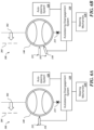
- a level of force applied to the steering wheel 140 is represented with an arrow (e.g., 201 in FIG. 2 A ).
- the arrow is representative of a force applied to a portion of the steering wheel 140 that acts as a moment arm such that the force represented by the arrow results in a rotational force applied to the steering wheel 140 .
- the length of the respective arrows are representative of the relative level of force applied by the operator to the steering wheel 140 .
- Threshold levels of force required to disengage the autosteering system 120 are represented by dashed lines (e.g., 205 in FIG. 2 A ).
- dashed lines e.g., 205 in FIG. 2 A
- the threshold level of force to disengage the autosteering system 120 without first engaging the turn signal 150 or other release input is designated as the default threshold.
- the autosteering disengagement system 110 may reduce the threshold level of force dictated by the default threshold to a lower, adjusted threshold when the release input has been engaged.
- the turn signal 150 represents the release input to reduce the threshold level of force to disengage the autosteering system 120 .
- the turn signal 150 is not the only release input that may be used with embodiments of the autosteering disengagement system 110 .
- a force 201 is applied to the steering wheel 140 .
- the turn signal 150 remains at its starting position 255 , thus, the release input has not been engaged. Because the turn signal 150 has not been engaged, no adjusted threshold is applied that might provide for disengaging the autosteering system 120 with application of a lesser level of force than imposed by a default threshold 205 .
- the force 201 applied is short of the default threshold 205 to disengage the autosteering system 120 .
- the autosteering system 120 remains engaged because the force 201 applied to the steering wheel 140 is not sufficient to engage the manual steering system, as represented by the X 215 indicating that the steering wheel 140 is not controlling the steering mechanism 130 .
- a force 202 larger than the force 201 ( FIG. 2 A ) is applied to the steering wheel 140 .
- the turn signal 150 remains at its starting position 255 , thus, the release input has not been engaged, and no adjusted threshold is applied that might provide for disengaging the autosteering system 120 with application of a lesser level of force than imposed by the default threshold 205 .
- the force 202 surpasses the default threshold 205 .
- the autosteering system 120 is disengaged, as represented by the X 225 indicating that the autosteering system 120 is disengaged from the steering mechanism 130 .
- the force 202 applied to the steering wheel 140 when it overcomes the default threshold 205 , may result in the steering wheel 140 being turned through an angle ⁇ .
- the autosteering disengagement system 110 enables disengagement of the autosteering system 120 without using a release input such as the turn signal 150 .
- the turn signal 150 is moved from a starting position 255 to an active position 355 which, in the example of FIGS. 3 A and 3 B , includes a left-turn position.
- An adjusted threshold 305 e.g., a threshold lower than default threshold 205
- a force 301 is applied to the steering wheel 140 .
- the force 301 does not meet the adjusted threshold 305 or the default threshold 205 , thus, the autosteering system 120 remains engaged.
- a force 302 larger than the force 301 ( FIG. 3 A ) is applied to the steering wheel 140 .
- the turn signal 150 was moved from its starting position 255 to the active position 355 , the release input has been engaged, the adjusted threshold 305 is applied, and the force 302 surpasses the adjusted threshold 305 .
- the autosteering system 120 is disengaged, as represented by the X 225 indicating that the autosteering system 120 is disengaged from the steering mechanism 130 .
- the force 302 applied to the steering wheel 140 when it overcomes the adjusted threshold 305 , may result in the steering wheel 140 being turned through an angle ⁇ .
- the steering wheel 140 may abruptly turn or “jerk” through an angle ⁇ ( FIG. 2 B ).
- the steering wheel 140 may move through a lesser angle ⁇ , resulting in less abrupt maneuver.
- the autosteering disengagement system 110 may enable an operator may be able to initiate a manual steering maneuver without abruptly turning or jerking the wheel.
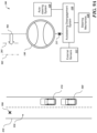
- a vehicle 400 including the autosteering disengagement system 110 is traveling on a road 410 and the operator chooses to disengage the autosteering system 120 to pass another vehicle 420 .
- the force 202 required to disengage the autosteering system 120 resulted in the steering wheel 140 being turned through an angle ⁇ .
- the resulting movement of the vehicle 400 to a new position 290 includes veering at an angle ⁇ .
- a new position 290 represented in dashed lines
- the lesser force 302 (as compared to the force 202 ) required to disengage the autosteering system 120 resulted in the steering wheel being turned through an angle ⁇ .
- the angle ⁇ is less than the angle ⁇ that was the product of the force 202
- the resulting movement of the vehicle 400 moving to a new position 390 (represented in dotted lines) is at a lesser angle ⁇ .
- the autosteering disengagement system 110 enables an operator to take deliberate action to intentionally disengage the autosteering system 120 and assert manual steering control with less extreme steering changes.
- the autosteering disengagement system 110 may impose a secondary condition (i.e., a secondary predetermined condition) before reducing the threshold level of force from the default threshold 205 to the adjusted threshold 305 .
- a secondary condition may impose a requirement that the release input be engaged before the force is applied to the steering wheel and/or that the release input be engaged to indicate a direction of the manual steering operation consistent with the direction of the force applied to the wheel, as further described with reference to FIGS. 5 A- 7 B .
- an operator moves the turn signal 150 from a starting position 255 to a right-turn position 555 .
- An adjusted threshold 505 is applied as a result of the operator engaging the release input in the form of the turn signal 150 .
- the adjusted threshold 505 is applied only to a right-hand maneuver and the default threshold 205 remains applied for the left-hand maneuver.
- the force 302 which was sufficient to surpass the adjusted threshold 305 ( FIGS. 3 A and 3 B ) and disengage the autosteering system 120 , does not result in disengagement of the autosteering system 120 . Because the turn signal 150 was moved to a right-turn position 555 , the adjusted threshold 305 was not applied for a left-hand maneuver. The force 302 also is not sufficient to surpass the default threshold 205 to disengage the autosteering system.
- the autosteering disengagement system 110 may be configured to prevent incidental contacts with both the turn signal 150 as release input and the steering wheel 140 if the engagement of the release input and steering wheel 140 are not consistent with each other (i.e., a predetermined condition of consistency between the engagement of the release input and the steering wheel) in order to manifest an operator's intention to disengage the autosteering system 120 .
- an operator applies the force 302 that would have been sufficient to reach the adjusted threshold 305 ( FIGS. 3 A and 3 B ) and, thus, disengage the autosteering system 120 .
- the adjusted threshold 305 was not applied. Because the adjusted threshold 305 was not applied and the force 302 is not sufficient to reach the default threshold 205 , the autosteering system 120 remains engaged.
- the operator then moves the turn signal 150 to the left-turn position 355 .
- the turn signal 150 being moved into the left-turn position 355 while the force 302 in excess of the adjusted threshold has already been applied is not sufficient to apply the adjusted threshold 305 .
- the autosteering disengagement system 110 may be configured to require a predetermined condition be met that the turn signal 150 or other release input be engaged before a force sufficient to overcome the adjusted threshold is applied.
- the autosteering disengagement system 110 may be further configured to prevent incidental contacts with a release input and the steering wheel 140 from unintentionally disengaging the autosteering system 120 .
- an operator moves the turn signal 150 to the left-turn position to apply the adjusted threshold 305 but applies a force 301 that is not sufficient to reach the adjusted threshold 305 to disengage the autosteering system 120 .
- the operator increases the force applied to the force 302 that would be sufficient to reach the adjusted threshold 305 ( FIG. 7 A ).
- the operator has moved the turn signal 150 back to the starting position 255 , thereby withdrawing the adjusted threshold 305 .
- the force 302 is not sufficient to disengage the autosteering system 120 .
- the autosteering disengagement system 110 may be configured to require a predetermined condition be met that the turn signal 150 or other release input be engaged and its engagement maintained before a force sufficient to overcome the adjusted threshold 305 is applied.
- the autosteering disengagement system 110 may be further configured to prevent incidental contacts with both the release input and the steering wheel 140 from unintentionally disengaging the autosteering system 120 .
- the autosteering disengagement system 110 may dictate application of a higher threshold level of force to disengage the autosteering system 120 .
- the default threshold may be increased to an adjusted threshold.
- the autosteering disengagement system 110 may dictate application of a higher threshold level of force to be sure that the operator intends to retake manual control before disengaging the autosteering system 120 .
- the autosteering disengagement system 110 is used in an automatically-steered vehicle 860 that travels a road 850 under control of the autosteering system 120 .
- the autosteering disengagement system 110 responds to external conditions detected by the external sensors 113 to change a threshold level of force required to disengage the autosteering system 120 .
- a now manually-steered vehicle 862 responds to operator control of the steering mechanism 130 .
- the force 201 is applied to the steering wheel 140 .
- the force 801 applied is short of the default threshold 205 to disengage the autosteering system 120 , as in the examples of FIGS. 2 A and 3 A .
- the autosteering system 120 remains engaged because the force 201 applied to the steering wheel 140 is not sufficient to engage the manual steering system, as represented by the X 215 indicating that the steering wheel 140 is not engaged with the steering mechanism 130 .
- a force 802 larger than the force 201 ( FIGS. 2 A, 3 A, and 8 A ) is applied to the steering wheel 140 .
- the force 802 surpasses the default threshold 205 .
- the autosteering system 120 is disengaged, as represented by the X 225 indicating that the autosteering system 120 is disengaged from the steering mechanism 130 .
- the autosteering disengagement system 110 enables disengagement of the autosteering system 120 as a result of the application of the force 802 in excess of the default threshold 205 .
- the now manually-steered vehicle 862 responds to operator control of the steering mechanism 130 .
- the vehicle 860 follows a second vehicle 970 , and an operator applies a force 901 in excess of the default threshold 205 in an effort to take manual steering control of the vehicle 860 to pass the second vehicle 970 .
- the external sensors 113 detect an obstacle 990 in an adjoining lane 950 that would be in the path of the vehicle 860 if the operator takes manual steering control of the vehicle 860 .
- the autosteering disengagement system 110 In response to detecting the external condition (i.e., in response to detecting that a predetermined condition of detecting an external condition is met) presented by the obstacle 990 , the autosteering disengagement system 110 applies an adjusted threshold 905 that dictates application of a higher level of force to disengage the autosteering system 120 .
- the force 901 does not meet the adjusted threshold 905 , thus, the autosteering system 120 remains engaged and the steering wheel 140 is not engaged with the steering mechanism 130 as represented by the X 215 .
- an operator applies a higher force 902 to the steering wheel 140 that surpasses the adjusted threshold 905 .
- the autosteering system 120 is disengaged, as represented by the X 225 indicating that the autosteering system 120 is disengaged from the steering mechanism 130 .
- the manually-steered vehicle 862 moves into the adjoining lane 950 .
- the autosteering disengagement system 110 by applying the increased, adjusted threshold 905 upon detecting the external condition 990 , provides a measure of added driver intentionality by requiring the operator to apply a greater level of force to the steering wheel 140 to disengage the autosteering system 120 .
- an unsafe condition 1090 adjacent to the road 850 is detected by the external sensors 113 .
- the unsafe condition 1090 may be a collapsed shoulder, a ditch, a cliff, water, debris, one or more stopped vehicles, or another condition that abuts or encroaches upon the road 850 .
- the external sensors 113 may include a GPS or other devices that receive information about the unsafe condition 1090 or that directly detect the unsafe condition 1090 .
- the operator applies the force 901 that surpasses the default threshold 205 in an attempt to disengage the autosteering system 120 .
- the autosteering disengagement system 110 applies the higher, adjusted threshold 905 that dictates application of a higher level of force to disengage the autosteering system 120 .
- the force 901 does not meet the adjusted threshold 905 , thus, the autosteering system 120 remains engaged and the steering wheel 140 is not engaged with the steering mechanism 130 as represented by the X 215 .
- an operator applies the higher force 902 to the steering wheel 140 that surpasses the adjusted threshold 905 .
- the autosteering system 120 is disengaged, as represented by the X 225 indicating that the autosteering system 120 is disengaged from the steering mechanism 130 .
- the now manually-steered vehicle 862 responds to operator control of the steering mechanism 130 .
- the autosteering disengagement system 110 by applying the increased, adjusted threshold 905 upon detecting the unsafe condition 1090 , provides a measure of added driver intentionality by requiring the operator to apply a greater level of force to the steering wheel 140 to disengage the autosteering system 120 .
- an external condition in the form of a second vehicle 1170 approaching the vehicle 860 is detected by the external sensors 113 .
- the external sensors 113 may include a blind spot detection system or other proximity detection system.
- the operator applies the force 901 that surpasses the default threshold 205 in an attempt to disengage the autosteering system 120 .
- the autosteering disengagement system 110 applies the higher, adjusted threshold 905 that dictates application of a higher level of force to disengage the autosteering system 120 .
- the force 901 does not meet the adjusted threshold 905 , thus, the autosteering system 120 remains engaged and the steering wheel 140 is not engaged with the steering mechanism 130 as represented by the X 215 .
- an operator applies the higher force 902 to the steering wheel 140 that surpasses the adjusted threshold 905 .
- the autosteering system 120 is disengaged, as represented by the X 225 indicating that the autosteering system 120 is disengaged from the steering mechanism 130 .
- the now manually-steered vehicle 862 responds to operator control of the steering mechanism 130 .
- the autosteering disengagement system 110 by applying the increased, adjusted threshold 905 upon detecting the second vehicle 1170 , provides a measure of added driver intentionality by requiring the operator to apply a greater level of force to the steering wheel 140 to disengage the autosteering system 120 .
- the steering wheel 140 or a dashboard or console 1210 in a cabin of a vehicle may include different and/or additional release inputs.
- the turn signal 150 may be employed as the release input.
- the steering wheel 140 may include one or more release buttons 1221 and 1222 as release inputs that may be depressed to apply the lower threshold to release the autosteering system 120 .
- the release buttons 1221 and 1222 may be disposed on opposing sides of the steering wheel 140 .
- the autosteering disengagement system 110 may require that a predetermined condition be met that the release button 1221 and 1222 on a side toward which the force is applied be engaged in order to apply the adjusted threshold.
- the release buttons 1221 and 1222 (placed on the steering wheel 140 ) may be engaged by an operator without the operator removing his or her hands from the wheel.
- an audio input interface 1230 such as a microphone, may be used to receive a verbal command from the operator as a release input.
- other inputs, including other buttons or keys 1240 on the dashboard or console 1210 may also be used as release inputs.
- an operator 1300 may change the threshold settings 1302 .
- the operator 1300 may use an interface 1305 , such as vehicle interface 850 ( FIG. 8 ) in communication with the autosteering disengagement system 110 .
- the thresholds also may be set using another computing device 1280 ( FIG. 12 ), such as a smartphone or a computer, that is able to interface with the autosteering disengagement system 110 via a wired or wireless interface 1290 directly or via a network.
- the operator 1300 may set a level of a reduced adjusted threshold 1310 , such as may be applied when a release input is used to corroborate the intent of the operator 1300 to take manual steering control of the vehicle as described with reference to FIGS. 2 A- 7 B .
- the operator 1300 may set a level of an increased adjusted threshold 1315 , such as may be applied when the external sensors 113 detect an external condition as described with reference to FIGS. 8 A- 11 B .
- the threshold levels 1310 and 1315 may be set between a minimum level 1330 and a maximum level 1340 to adjust the thresholds 1310 and 1315 from current levels 1350 to new levels 1360 and thereby set a difference between the thresholds 1310 and 1315 and a default threshold 1305 .
- different operators may prefer different threshold settings 1402 and 1403 , which operator A 1412 and operator B 1413 each may set as described with reference to FIG. 9 .
- the threshold settings 1402 and 1403 may be associated with operating credentials 1422 and 1423 (represented by key fobs associated with operator A 1412 and operator B 1413 , respectively).
- the operating credentials may be verified at the vehicle or via a remote system (e.g., via a network-based or cloud-based system) with image recognition, voice recognition, or another form of authentication.
- the appropriate threshold settings 1402 and 1403 may be applied.
- a vehicle 1500 includes an integrated vehicle control system 1510 that controls operation of the vehicle 1500 .
- the vehicle control system 1510 may incorporate or interoperate with the autosteering disengagement system 110 .
- the vehicle control system 1510 may incorporate or interoperate with the autosteering system 120 (not separately shown in FIG. 15 ).
- the vehicle 1500 includes a body 1502 that may include a cabin 1504 capable of accommodating an operator, one or more passengers, and/or cargo and a cargo area 1506 separate from the cabin 1504 , such as a trunk or a truck bed, capable of transporting cargo.
- the vehicle 1500 includes a drive system 1520 , as further described below, which is selectively engageable with one or more front wheels 1522 and/or one or more rear wheels 1524 to motivate, accelerate, decelerate, stop, and steer the vehicle 1500 .
- the autosteering disengagement system 110 may be used with an electrically-powered vehicle 1600 .
- the wheels 1612 and/or 1614 may be motivated by one or more electrically-powered drive systems 1620 and/or 1630 , such as motors, operably coupled with the wheels 1612 and/or 1614 .
- the drive systems 1620 and 1630 draw power from a battery system 1610 , which also may be used to power the autosteering disengagement system 110 and other vehicle systems.
- the autosteering disengagement system 110 may be used with an internal combustion engine-powered vehicle 1700 .
- the wheels 1712 and/or 1714 may be motivated by an internal combustion or hybrid engine 1720 coupled with a fuel tank 1710 via a fuel line 1712 .
- the engine 1720 may be coupled to the wheels 1712 and/or 1714 by mechanical linkages 1730 and 1740 , respectively, including axles, transaxles, or other drive train systems to provide rotational force to power the wheels 1712 and/or 1714 .
- FIGS. 15 - 17 show four-wheeled land vehicles.
- the autosteering disengagement system 110 may be integrated with other vehicles that include autosteering systems.
- the autosteering disengagement system 110 may include a general purpose computing device 1800 configured to operate according to computer-executable instructions for controlling disengagement of an autosteering system as herein described.
- the computing device 1800 typically includes at least one processing unit 1820 and a system memory 1830 .
- the system memory 1830 may include volatile memory, such as random-access memory (“RAM”), non-volatile memory, such as read-only memory (“ROM”), flash memory, and the like, or a combination of volatile memory and non-volatile memory.
- RAM random-access memory
- ROM read-only memory
- flash memory and the like
- the system memory 1830 typically maintains an operating system 1831 , one or more applications 1832 , and program data 1834 .
- the operating system 1831 may include any number of operating systems executable on desktop or portable devices including, but not limited to, Linux, Microsoft Windows®, Apple iOS®, or Android®, or a proprietary operating system.
- the applications 1832 may include instructions implementing functions of the autosteering disengagement system 110 as previously described.
- the program data 1834 may include the threshold data 114 ( FIG. 1 ) used by the autosteering disengagement system 110 as previously described.
- the computing device 1800 may also have additional features or functionality.
- the computing device 1800 may also include additional data storage devices (removable and/or non-removable) such as, for example, magnetic disks, optical disks, tape, or flash memory.
- additional storage devices are illustrated in FIG. 18 by removable storage 1840 and non-removable storage 1850 .
- Computer storage media may include volatile and non-volatile, removable and non-removable media implemented in any method or technology for storage of information, such as computer-readable instructions, data structures, program modules or other data.
- the system memory 1830 , the removable storage 1840 , and the non-removable storage 1850 are all examples of computer storage media.
- Computer storage media include, but are not limited to, RAM, ROM, EEPROM, flash memory (in both removable and non-removable forms) or other memory technology, CD-ROM, digital versatile disks (DVD) or other optical storage, magnetic cassettes, magnetic disk storage or other magnetic storage devices, or any other medium which can be used to store the desired information and which can be accessed by the computing device 1800 . Any such computer storage media may be part of the computing device 1800 .
- the computing device 1800 may also have input device(s) 1860 such as a keyboard, stylus, voice input device, touchscreen input device, etc.
- Output device(s) 1870 such as a display, speakers, short-range transceivers such as a Bluetooth transceiver, etc., may also be included.
- the computing device 1800 also may include one or more communication systems 1880 that allow the computing device 1800 to communicate with other computing systems 1890 , such as those described previously with reference to FIG. 13 .
- the communication system 1880 may include systems for wired or wireless communications. Available forms of communication media typically carry computer-readable instructions, data structures, program modules or other data in a modulated data signal such as a carrier wave or other transport mechanism and includes any information delivery media.
- modulated data signal may include a signal that has one or more of its characteristics set or changed in such a manner as to encode information in the signal.
- communications media may include wired media such as a wired network or direct-wired connection, and wireless media such as acoustic, radio frequency (RF), infrared and other wireless media.
- RF radio frequency
- computer-readable media includes both storage media and communication media.
- an illustrative method 1900 is provided for selectively disengaging the autosteering system of a vehicle.
- the method 1900 starts at a block 1905 .
- a block 1910 it is recognizing that a vehicle is operating in an autosteering mode in which a vehicle control system guides steering of the vehicle.
- a level of force applied by an operator to a steering wheel of the vehicle is detected.
- the vehicle is switched from the autosteering mode to a manual steering mode under control of the operator when the level of force surpasses a threshold chosen from a default threshold and an adjusted threshold that is applied upon detecting a predetermined condition for applying the adjusted threshold, as previously described with reference to FIGS. 2 A- 12 .
- the method 1900 ends at a block 1935 .
- a data processing system generally includes one or more of a system unit housing, a video display device, memory such as volatile or non-volatile memory, processors such as microprocessors or digital signal processors, computational entities such as operating systems, drivers, graphical user interfaces, and applications programs, one or more interaction devices (e.g., a touch pad, a touch screen, an antenna, etc.), and/or control systems including feedback loops and control motors (e.g., feedback for sensing position and/or velocity; control motors for moving and/or adjusting components and/or quantities).
- a data processing system may be implemented utilizing suitable commercially available components, such as those typically found in data computing/communication and/or network computing/communication systems.
- module may refer to a collection of one or more components that are arranged in a particular manner, or a collection of one or more general-purpose components that may be configured to operate in a particular manner at one or more particular points in time, and/or also configured to operate in one or more further manners at one or more further times.
- the same hardware, or same portions of hardware may be configured/reconfigured in sequential/parallel time(s) as a first type of module (e.g., at a first time), as a second type of module (e.g., at a second time, which may in some instances coincide with, overlap, or follow a first time), and/or as a third type of module (e.g., at a third time which may, in some instances, coincide with, overlap, or follow a first time and/or a second time), etc.
- a first type of module e.g., at a first time
- a second type of module e.g., at a second time, which may in some instances coincide with, overlap, or follow a first time
- a third type of module e.g., at a third time which may, in some instances, coincide with, overlap, or follow a first time and/or a second time
- Reconfigurable and/or controllable components are capable of being configured as a first module that has a first purpose, then a second module that has a second purpose and then, a third module that has a third purpose, and so on.
- the transition of a reconfigurable and/or controllable component may occur in as little as a few nanoseconds, or may occur over a period of minutes, hours, or days.
- the component may no longer be capable of carrying out that first purpose until it is reconfigured.
- a component may switch between configurations as different modules in as little as a few nanoseconds.
- a component may reconfigure on-the-fly, e.g., the reconfiguration of a component from a first module into a second module may occur just as the second module is needed.
- a component may reconfigure in stages, e.g., portions of a first module that are no longer needed may reconfigure into the second module even before the first module has finished its operation. Such reconfigurations may occur automatically, or may occur through prompting by an external source, whether that source is another component, an instruction, a signal, a condition, an external stimulus, or similar.
- a central processing unit of a personal computer may, at various times, operate as a module for displaying graphics on a screen, a module for writing data to a storage medium, a module for receiving user input, and a module for multiplying two large prime numbers, by configuring its logical gates in accordance with its instructions.
- Such reconfiguration may be invisible to the naked eye, and in some embodiments may include activation, deactivation, and/or re-routing of various portions of the component, e.g., switches, logic gates, inputs, and/or outputs.
- an example includes or recites multiple modules
- the example includes the possibility that the same hardware may implement more than one of the recited modules, either contemporaneously or at discrete times or timings.
- the implementation of multiple modules, whether using more components, fewer components, or the same number of components as the number of modules, is merely an implementation choice and does not generally affect the operation of the modules themselves. Accordingly, it should be understood that any recitation of multiple discrete modules in this disclosure includes implementations of those modules as any number of underlying components, including, but not limited to, a single component that reconfigures itself over time to carry out the functions of multiple modules, and/or multiple components that similarly reconfigure, and/or special purpose reconfigurable components.
- one or more components may be referred to herein as “configured to,” “configured by,” “configurable to,” “operable/operative to,” “adapted/adaptable,” “able to,” “conformable/conformed to,” etc.
- Those skilled in the art will recognize that such terms (for example “configured to”) generally encompass active-state components and/or inactive-state components and/or standby-state components, unless context requires otherwise.
- ASICs Application Specific Integrated Circuits
- FPGAs Field Programmable Gate Arrays
- DSPs digital signal processors
- ASICs Application Specific Integrated Circuits
- FPGAs Field Programmable Gate Arrays
- DSPs digital signal processors
- aspects of the embodiments disclosed herein, in whole or in part, can be equivalently implemented in integrated circuits, as one or more computer programs running on one or more computers (e.g., as one or more programs running on one or more computer systems), as one or more programs running on one or more processors (e.g., as one or more programs running on one or more microprocessors), as firmware, or as virtually any combination thereof, limited to patentable subject matter under 35 U.S.C.
- Examples of a signal bearing medium include, but are not limited to, the following: a recordable type medium such as a floppy disk, a hard disk drive, a Compact Disc (CD), a Digital Video Disk (DVD), a digital tape, a computer memory, etc.; and a transmission type medium such as a digital and/or an analog communication medium (e.g., a fiber optic cable, a waveguide, a wired communications link, a wireless communication link (e.g., transmitter, receiver, transmission logic, reception logic, etc.), etc.).
- a recordable type medium such as a floppy disk, a hard disk drive, a Compact Disc (CD), a Digital Video Disk (DVD), a digital tape, a computer memory, etc.
- a transmission type medium such as a digital and/or an analog communication medium (e.g., a fiber optic cable, a waveguide, a wired communications link, a wireless communication link (e.g., transmitter, receiver, transmission logic, reception
Landscapes
- Engineering & Computer Science (AREA)
- Transportation (AREA)
- Mechanical Engineering (AREA)
- Chemical & Material Sciences (AREA)
- Combustion & Propulsion (AREA)
- Automation & Control Theory (AREA)
- Steering Control In Accordance With Driving Conditions (AREA)
Abstract
Description
Claims (16)
Priority Applications (3)
| Application Number | Priority Date | Filing Date | Title |
|---|---|---|---|
| US17/386,626 US12151740B2 (en) | 2021-07-28 | 2021-07-28 | Dynamic autosteering disengagement |
| DE102022101900.4A DE102022101900A1 (en) | 2021-07-28 | 2022-01-27 | DYNAMIC SHUTDOWN OF AUTO STEERING |
| CN202210096877.XA CN115675643A (en) | 2021-07-28 | 2022-01-27 | Dynamic automatic steering cut-off |
Applications Claiming Priority (1)
| Application Number | Priority Date | Filing Date | Title |
|---|---|---|---|
| US17/386,626 US12151740B2 (en) | 2021-07-28 | 2021-07-28 | Dynamic autosteering disengagement |
Publications (2)
| Publication Number | Publication Date |
|---|---|
| US20230033338A1 US20230033338A1 (en) | 2023-02-02 |
| US12151740B2 true US12151740B2 (en) | 2024-11-26 |
Family
ID=84890138
Family Applications (1)
| Application Number | Title | Priority Date | Filing Date |
|---|---|---|---|
| US17/386,626 Active 2042-06-16 US12151740B2 (en) | 2021-07-28 | 2021-07-28 | Dynamic autosteering disengagement |
Country Status (3)
| Country | Link |
|---|---|
| US (1) | US12151740B2 (en) |
| CN (1) | CN115675643A (en) |
| DE (1) | DE102022101900A1 (en) |
Citations (11)
| Publication number | Priority date | Publication date | Assignee | Title |
|---|---|---|---|---|
| US20020177935A1 (en) * | 2001-03-24 | 2002-11-28 | Hermann Winner | Tracking and driving speed regulating device for motor vehicles |
| US20040262063A1 (en) * | 2003-06-11 | 2004-12-30 | Kaufmann Timothy W. | Steering system with lane keeping integration |
| US20090216404A1 (en) * | 2005-10-07 | 2009-08-27 | Alexander Maass | Driver Assistance System |
| DE112017000550T5 (en) | 2016-01-29 | 2018-10-18 | Joyson Safety Systems Acquisition Llc | Systems and methods for detecting steering wheel contact |
| DE112016005745T5 (en) | 2015-12-15 | 2018-11-15 | Jaguar Land Rover Limited | Attenuation of unequal braking effect |
| US20190047621A1 (en) * | 2017-08-10 | 2019-02-14 | Hyundai Motor Company | Lane keeping assist method and system |
| US20190071081A1 (en) * | 2017-09-06 | 2019-03-07 | Honda Motor Co., Ltd. | Driving support device and driving support method |
| DE112018003470T5 (en) | 2017-07-06 | 2020-03-19 | Joyson Safety Systems Acquisition Llc | SYSTEM AND METHOD FOR DETECTING THE MOVEMENT OF A PASSENGER IN A VEHICLE |
| US20210197813A1 (en) * | 2019-12-27 | 2021-07-01 | Lyft, Inc. | Systems and methods for appropriate speed inference |
| DE102022114511A1 (en) | 2021-06-28 | 2022-12-29 | Nvidia Corporation | Resting the state to optimize start-up processes of autonomous vehicles |
| DE102022109372A1 (en) | 2021-07-23 | 2023-01-26 | GM Global Technology Operations LLC | User interface for assigning unsupervised periods during automatic control of a device |
-
2021
- 2021-07-28 US US17/386,626 patent/US12151740B2/en active Active
-
2022
- 2022-01-27 CN CN202210096877.XA patent/CN115675643A/en active Pending
- 2022-01-27 DE DE102022101900.4A patent/DE102022101900A1/en active Pending
Patent Citations (11)
| Publication number | Priority date | Publication date | Assignee | Title |
|---|---|---|---|---|
| US20020177935A1 (en) * | 2001-03-24 | 2002-11-28 | Hermann Winner | Tracking and driving speed regulating device for motor vehicles |
| US20040262063A1 (en) * | 2003-06-11 | 2004-12-30 | Kaufmann Timothy W. | Steering system with lane keeping integration |
| US20090216404A1 (en) * | 2005-10-07 | 2009-08-27 | Alexander Maass | Driver Assistance System |
| DE112016005745T5 (en) | 2015-12-15 | 2018-11-15 | Jaguar Land Rover Limited | Attenuation of unequal braking effect |
| DE112017000550T5 (en) | 2016-01-29 | 2018-10-18 | Joyson Safety Systems Acquisition Llc | Systems and methods for detecting steering wheel contact |
| DE112018003470T5 (en) | 2017-07-06 | 2020-03-19 | Joyson Safety Systems Acquisition Llc | SYSTEM AND METHOD FOR DETECTING THE MOVEMENT OF A PASSENGER IN A VEHICLE |
| US20190047621A1 (en) * | 2017-08-10 | 2019-02-14 | Hyundai Motor Company | Lane keeping assist method and system |
| US20190071081A1 (en) * | 2017-09-06 | 2019-03-07 | Honda Motor Co., Ltd. | Driving support device and driving support method |
| US20210197813A1 (en) * | 2019-12-27 | 2021-07-01 | Lyft, Inc. | Systems and methods for appropriate speed inference |
| DE102022114511A1 (en) | 2021-06-28 | 2022-12-29 | Nvidia Corporation | Resting the state to optimize start-up processes of autonomous vehicles |
| DE102022109372A1 (en) | 2021-07-23 | 2023-01-26 | GM Global Technology Operations LLC | User interface for assigning unsupervised periods during automatic control of a device |
Also Published As
| Publication number | Publication date |
|---|---|
| CN115675643A (en) | 2023-02-03 |
| DE102022101900A1 (en) | 2023-02-02 |
| US20230033338A1 (en) | 2023-02-02 |
Similar Documents
| Publication | Publication Date | Title |
|---|---|---|
| US11040620B2 (en) | User interface apparatus for vehicle, and vehicle | |
| US11235759B2 (en) | Vehicle control method thereof | |
| US10246095B2 (en) | Regenerative braking control apparatus for vehicles | |
| CN105261224B (en) | Intelligent vehicle control method and apparatus | |
| US20190118801A1 (en) | Device for automatically parking vehicle and method for controlling the same | |
| US10942523B2 (en) | Autonomous vehicle and method of controlling the same | |
| US11740622B2 (en) | Remote trailer maneuver-assist | |
| US20190276044A1 (en) | User interface apparatus for vehicle and vehicle including the same | |
| CN110884485A (en) | Automatic parking device and automatic parking method | |
| CN107472245A (en) | Adaptive cruise control system and vehicle including the same | |
| KR20200022675A (en) | Remote control device, remote parking assist system using the same and control method thereof | |
| US9963068B2 (en) | Vehicle proximity condition detection and haptic notification system | |
| CN109863060A (en) | For controlling the method for the massage unit for the massage apparatus being arranged in seat, for the seat arrangement in vehicle or vehicle | |
| KR20210143344A (en) | Vehicle control device and control method of the device | |
| US11112786B2 (en) | Remote trailer maneuver-assist | |
| US20230037006A1 (en) | Map positioning via indication of turn intention | |
| US12151740B2 (en) | Dynamic autosteering disengagement | |
| KR102387610B1 (en) | Vehicle and Control method thereof | |
| US12084048B2 (en) | Physical feedback confirmation from assisted- driving system about traffic event | |
| US11292484B2 (en) | Vehicle control device, vehicle, and vehicle control method | |
| US20220155778A1 (en) | Systems and methods for providing enhanced feedback on a personal communication device used for vehicle maneuvering | |
| CN106232461A (en) | Automatic parking method and apparatus | |
| CN112660162B (en) | Low-speed driving control method and device and vehicle | |
| US20160147322A1 (en) | System and method for identifying a user of a vehicle head unit | |
| US11400953B2 (en) | Method and product for alerting or refocusing an inattentive driver |
Legal Events
| Date | Code | Title | Description |
|---|---|---|---|
| AS | Assignment |
Owner name: RIVIAN AUTOMOTIVE, LLC, MICHIGAN Free format text: ASSIGNMENT OF ASSIGNORS INTEREST;ASSIGNORS:KOH, KOK WEI;KULKARNI, ROHAN;GURUSUBRAMANIAN, SABA;SIGNING DATES FROM 20210713 TO 20210719;REEL/FRAME:056999/0303 Owner name: RIVIAN IP HOLDINGS, LLC, MICHIGAN Free format text: ASSIGNMENT OF ASSIGNORS INTEREST;ASSIGNOR:RIVIAN AUTOMOTIVE, LLC;REEL/FRAME:056999/0341 Effective date: 20210719 |
|
| FEPP | Fee payment procedure |
Free format text: ENTITY STATUS SET TO UNDISCOUNTED (ORIGINAL EVENT CODE: BIG.); ENTITY STATUS OF PATENT OWNER: LARGE ENTITY |
|
| STPP | Information on status: patent application and granting procedure in general |
Free format text: DOCKETED NEW CASE - READY FOR EXAMINATION |
|
| STPP | Information on status: patent application and granting procedure in general |
Free format text: NON FINAL ACTION MAILED |
|
| STPP | Information on status: patent application and granting procedure in general |
Free format text: RESPONSE TO NON-FINAL OFFICE ACTION ENTERED AND FORWARDED TO EXAMINER |
|
| STPP | Information on status: patent application and granting procedure in general |
Free format text: FINAL REJECTION MAILED |
|
| STPP | Information on status: patent application and granting procedure in general |
Free format text: ADVISORY ACTION COUNTED, NOT YET MAILED |
|
| STPP | Information on status: patent application and granting procedure in general |
Free format text: ADVISORY ACTION MAILED |
|
| STPP | Information on status: patent application and granting procedure in general |
Free format text: DOCKETED NEW CASE - READY FOR EXAMINATION |
|
| STPP | Information on status: patent application and granting procedure in general |
Free format text: NON FINAL ACTION MAILED |
|
| STPP | Information on status: patent application and granting procedure in general |
Free format text: RESPONSE TO NON-FINAL OFFICE ACTION ENTERED AND FORWARDED TO EXAMINER |
|
| STPP | Information on status: patent application and granting procedure in general |
Free format text: NOTICE OF ALLOWANCE MAILED -- APPLICATION RECEIVED IN OFFICE OF PUBLICATIONS |
|
| STPP | Information on status: patent application and granting procedure in general |
Free format text: PUBLICATIONS -- ISSUE FEE PAYMENT RECEIVED |
|
| STCF | Information on status: patent grant |
Free format text: PATENTED CASE |