US1215140A - Evaporator. - Google Patents
Evaporator. Download PDFInfo
- Publication number
- US1215140A US1215140A US8331616A US8331616A US1215140A US 1215140 A US1215140 A US 1215140A US 8331616 A US8331616 A US 8331616A US 8331616 A US8331616 A US 8331616A US 1215140 A US1215140 A US 1215140A
- Authority
- US
- United States
- Prior art keywords
- kettle
- liquid
- conduit
- evaporator
- pump
- Prior art date
- Legal status (The legal status is an assumption and is not a legal conclusion. Google has not performed a legal analysis and makes no representation as to the accuracy of the status listed.)
- Expired - Lifetime
Links
Images
Classifications
-
- B—PERFORMING OPERATIONS; TRANSPORTING
- B01—PHYSICAL OR CHEMICAL PROCESSES OR APPARATUS IN GENERAL
- B01D—SEPARATION
- B01D3/00—Distillation or related exchange processes in which liquids are contacted with gaseous media, e.g. stripping
- B01D3/06—Flash distillation
Definitions
- My invention relates to an evaporator whereby liquids may be rapidly evaporated, allowing the vapors therefrom to escape into 4 the open air, or to be condensed by any suitable means.
- the object of the invention is to provide a simple, inexpensive and efiicient evaporator which is particularly adapted for the rapid concentration of a solution; or the removal, by evaporation, of excess water, or alcohol, or of both alcohol and water as in the case of beer or Wine.
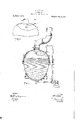
- Figure 1 is an elevation of the evaporator, the liquid container or kcttlebcing shown in. section, and part of the steam jacket about the delivery conduit also being in section to show the details of construction;
- Fig. 2 is a fragmentary elevation of a kettle partly in section to show the spray nozzle in a different position.
- 3 is the container or kettle for boiling liquids. It has preferably a steam jacket 4 at the bottom for supplying heat to the kettle to boil the liquid therein but any other suitable means maybe used. At the top the kettle has a flue or vent 5 for exhausting the vapors generated in the kettle. Rows of battle plates Gare provided in the vent at the top of the kettle to prevent liquid particles from being carried away by' the vapors. It will be noted that the rows of baiiies are disposed angularly to each other to form a sinuous path or passage for the vapors passing from the kettle to the vent.
- A. conduit extends from the bottom or the kettle to an inlet end of a pump 8, the delivery conduit 9 of which pump leads to the top of and into the kettle at a point above the highest possible liquid level within the kettle.
- the conduit 9 within the kettle terminates with a multiple nozzle or nozzles 10 to break up the liquid into fine particles.
- the conduit 5) is preferably surrounded with a live-steam jacket 11 to preheat the liquid circulating thcrcthrough to the boiling point.
- the vent 5 may be connected to a vacuum pump so as to cause the boiling of the liquid in the kettle under a diminished pressure.
- An evaporator ot the class described comprising a kettle tor boiling liquids, a pump, a conduit from the kettle,bottom to the pump inlet, a conduit from the pump outlet to the top of the kettle, a nozzle on said conduit within the kettle for breaking up the liquid into a finely divided spra v, means for carrying oil' the vapors from the kettle, and means for preheating the liquid in the conduit from the pump outlet to the kettle.
- An evaporator of the class described comprising a kettle for boiling liquids having a vapor exhaust at the top thereof, ballle plates in said exhaust, a pump adapted to draw liquid from the kettle and discharge the same into the kettle above the liquid level oi the kettle, means for breaking up the discharged liquid within the kettle into a finely divided spray, and means for preheating the liquid/o'n its discharge from the pump to the kettle.
- An evaporator of the class described comprising a kettle for boiling liquids having a vapor exhaust at the top thereof, angularly disposed rows of battle plates in the exhaust at the kettle, a pump, a conduit from the bottom of the kettle to the inlet of the pump, a conduit from the outlet of In testimony whereof I have signed my ⁇ the pump into the kettle at a point above name to this specification in the presence of no the liquid 1level ofghe ksttl fa riiultigletwo subscribing Witnesses.
Landscapes
- Chemical & Material Sciences (AREA)
- Chemical Kinetics & Catalysis (AREA)
- Vaporization, Distillation, Condensation, Sublimation, And Cold Traps (AREA)
- Cookers (AREA)
Description
W. J. GtLLER.
I EVAPORATOR.
APPLICATION FILED MAR. 10, 1916.
l 1L 5., 1L a V Patented Eel 0. 6, 1917.
- WITNESSES llV I/E/VTOR e... ax/w WALTER JOHN GILLER, OF WARSAW, ILLINOIS.
EVAPORATOR.
tarmac.
Specification of Letters Patent.
Patented Feb. (ii, 191?.
Application filed March 10, 1916. Serial No. 83,316.
To all whom it may concern:
Be it known that I, WALTERJ. GILLER, a citizen of the United States, and a resident of VVarsaw, in the county of Hancock and State of Illinois, have ini'enteda new and Improved Evaporator, of which the following is a fulLclear, and exact description.
My invention relates to an evaporator whereby liquids may be rapidly evaporated, allowing the vapors therefrom to escape into 4 the open air, or to be condensed by any suitable means.
The object of the invention is to provide a simple, inexpensive and efiicient evaporator which is particularly adapted for the rapid concentration of a solution; or the removal, by evaporation, of excess water, or alcohol, or of both alcohol and water as in the case of beer or Wine.
With the above and other objects in View, the nature of which will more fully appear as the description proceeds, the invention consists in the novel construction, combination and arrangement of parts as herein fully described, illustrated and claimed. n the accompanying drawings, forming part of the application, similar characters 0t reference indicate corresponding parts in botl. views. s
Figure 1 is an elevation of the evaporator, the liquid container or kcttlebcing shown in. section, and part of the steam jacket about the delivery conduit also being in section to show the details of construction; and
Fig. 2 is a fragmentary elevation of a kettle partly in section to show the spray nozzle in a different position.
Referring to the drawings, 3 is the container or kettle for boiling liquids. It has preferably a steam jacket 4 at the bottom for supplying heat to the kettle to boil the liquid therein but any other suitable means maybe used. At the top the kettle has a flue or vent 5 for exhausting the vapors generated in the kettle. Rows of battle plates Gare provided in the vent at the top of the kettle to prevent liquid particles from being carried away by' the vapors. It will be noted that the rows of baiiies are disposed angularly to each other to form a sinuous path or passage for the vapors passing from the kettle to the vent.
A. conduit extends from the bottom or the kettle to an inlet end of a pump 8, the delivery conduit 9 of which pump leads to the top of and into the kettle at a point above the highest possible liquid level within the kettle. The conduit 9 within the kettle terminates with a multiple nozzle or nozzles 10 to break up the liquid into fine particles. The conduit 5) is preferably surrounded with a live-steam jacket 11 to preheat the liquid circulating thcrcthrough to the boiling point.
The breaking up of a solution into line particles by the spray nozzle causes a. slight reduction in temperature, which will cause a condensation of the parts of the solution which have a higher boiling point, thus the vapors of the lighter constituents of the solution will escape through the vent, while thc other vapors will be retained in the kettle.
The vent 5 may be connected to a vacuum pump so as to cause the boiling of the liquid in the kettle under a diminished pressure.
I claim:
1. An evaporator ot the class described comprisinga kettle tor boiling liquids, a pump, a conduit from the kettle,bottom to the pump inlet, a conduit from the pump outlet to the top of the kettle, a nozzle on said conduit within the kettle for breaking up the liquid into a finely divided spra v, means for carrying oil' the vapors from the kettle, and means for preheating the liquid in the conduit from the pump outlet to the kettle.
2. An evaporator of the class described comprising a kettle for boiling liquids having a vapor exhaust at the top thereof, ballle plates in said exhaust, a pump adapted to draw liquid from the kettle and discharge the same into the kettle above the liquid level oi the kettle, means for breaking up the discharged liquid within the kettle into a finely divided spray, and means for preheating the liquid/o'n its discharge from the pump to the kettle.
3. An evaporator of the class described comprising a kettle for boiling liquids having a vapor exhaust at the top thereof, angularly disposed rows of battle plates in the exhaust at the kettle, a pump, a conduit from the bottom of the kettle to the inlet of the pump, a conduit from the outlet of In testimony whereof I have signed my\ the pump into the kettle at a point above name to this specification in the presence of no the liquid 1level ofghe ksttl fa riiultigletwo subscribing Witnesses. sprai 'nozz e.on sai con m or rea ng 5 up t; 6 liquid into finely divided sprays, and JOHN a state; in jacket on the conduit from the out- Witnesses: let dizthe pum' the kettle for preheating J. M. HUNGATT, the, ,j1jm1id flow mg; through the conduit. HENRY ZOBEL.
Priority Applications (1)
| Application Number | Priority Date | Filing Date | Title |
|---|---|---|---|
| US8331616A US1215140A (en) | 1916-03-10 | 1916-03-10 | Evaporator. |
Applications Claiming Priority (1)
| Application Number | Priority Date | Filing Date | Title |
|---|---|---|---|
| US8331616A US1215140A (en) | 1916-03-10 | 1916-03-10 | Evaporator. |
Publications (1)
| Publication Number | Publication Date |
|---|---|
| US1215140A true US1215140A (en) | 1917-02-06 |
Family
ID=3283028
Family Applications (1)
| Application Number | Title | Priority Date | Filing Date |
|---|---|---|---|
| US8331616A Expired - Lifetime US1215140A (en) | 1916-03-10 | 1916-03-10 | Evaporator. |
Country Status (1)
| Country | Link |
|---|---|
| US (1) | US1215140A (en) |
Cited By (8)
| Publication number | Priority date | Publication date | Assignee | Title |
|---|---|---|---|---|
| US2579944A (en) * | 1945-04-09 | 1951-12-25 | Colgate Palmolive Peet Co | Process and apparatus for coating particulate material |
| US2710057A (en) * | 1951-05-22 | 1955-06-07 | Lever Brothers Ltd | Tubular drying of soap |
| US2798542A (en) * | 1951-10-01 | 1957-07-09 | British Celanese | Concentration of viscous solutions |
| US2815321A (en) * | 1945-11-13 | 1957-12-03 | Eugene P Wigner | Isotope conversion device |
| US2996351A (en) * | 1956-06-29 | 1961-08-15 | Wacker Chemie Gmbh | Process for preventing corrosion of metals |
| US3113063A (en) * | 1960-12-28 | 1963-12-03 | Union Carbide Corp | Method of drying phosphoruscontaining acids |
| US3292999A (en) * | 1963-04-29 | 1966-12-20 | Chicago Bridge & Iron Co | Crystallizer with baffled recirculation flow |
| US3872910A (en) * | 1970-02-04 | 1975-03-25 | Bertrams Ag Hch | Method of concentrating caustic solutions |
-
1916
- 1916-03-10 US US8331616A patent/US1215140A/en not_active Expired - Lifetime
Cited By (8)
| Publication number | Priority date | Publication date | Assignee | Title |
|---|---|---|---|---|
| US2579944A (en) * | 1945-04-09 | 1951-12-25 | Colgate Palmolive Peet Co | Process and apparatus for coating particulate material |
| US2815321A (en) * | 1945-11-13 | 1957-12-03 | Eugene P Wigner | Isotope conversion device |
| US2710057A (en) * | 1951-05-22 | 1955-06-07 | Lever Brothers Ltd | Tubular drying of soap |
| US2798542A (en) * | 1951-10-01 | 1957-07-09 | British Celanese | Concentration of viscous solutions |
| US2996351A (en) * | 1956-06-29 | 1961-08-15 | Wacker Chemie Gmbh | Process for preventing corrosion of metals |
| US3113063A (en) * | 1960-12-28 | 1963-12-03 | Union Carbide Corp | Method of drying phosphoruscontaining acids |
| US3292999A (en) * | 1963-04-29 | 1966-12-20 | Chicago Bridge & Iron Co | Crystallizer with baffled recirculation flow |
| US3872910A (en) * | 1970-02-04 | 1975-03-25 | Bertrams Ag Hch | Method of concentrating caustic solutions |
Similar Documents
| Publication | Publication Date | Title |
|---|---|---|
| TWI675690B (en) | Atomizing separation method and atomizing separation device | |
| US1215140A (en) | Evaporator. | |
| KR20110005805A (en) | Ultrasonic humidifier | |
| US1067010A (en) | Evaporator. | |
| US235521A (en) | Edward fox | |
| US1511876A (en) | Degasifying apparatus | |
| US894407A (en) | Evaporator. | |
| US2315481A (en) | Method and apparatus for degasifying liquids | |
| US144358A (en) | Improvement in vacuum-pans for the manufacture of sugar | |
| US3344836A (en) | Revolving disc spray type evaporator | |
| US591138A (en) | William m | |
| US1105443A (en) | Multiple-effect evaporating apparatus. | |
| US441371A (en) | Concentrating and evaporating liquids | |
| JP2008096062A (en) | Evaporative cooling device | |
| US6080273A (en) | Method and device for treating liquids by partial evaporation | |
| WO2004047924A1 (en) | Deaeration apparatus for deaerating water used during ultrasonic focusing tumour treatment | |
| US161353A (en) | Improvement in evaporating apparatus | |
| US549001A (en) | Art of and apparatus for condensing and evaporating | |
| US326082A (en) | Milton w | |
| US339546A (en) | James b | |
| US967810A (en) | Apparatus for withdrawing air and water from steam-condensers. | |
| US148564A (en) | Improvement in steam-condensers | |
| US2457605A (en) | Feed-water heater | |
| US1330556A (en) | Diffusion-pump | |
| RU2002423C1 (en) | Small-scale vacuum evaporator plant |