US12146380B2 - Mandrel assemblies for a plug and associated methods - Google Patents
Mandrel assemblies for a plug and associated methods Download PDFInfo
- Publication number
- US12146380B2 US12146380B2 US17/610,008 US202017610008A US12146380B2 US 12146380 B2 US12146380 B2 US 12146380B2 US 202017610008 A US202017610008 A US 202017610008A US 12146380 B2 US12146380 B2 US 12146380B2
- Authority
- US
- United States
- Prior art keywords
- rod
- plug
- mandrel assembly
- wellbore
- packer
- Prior art date
- Legal status (The legal status is an assumption and is not a legal conclusion. Google has not performed a legal analysis and makes no representation as to the accuracy of the status listed.)
- Active, expires
Links
Images


Classifications
-
- E—FIXED CONSTRUCTIONS
- E21—EARTH OR ROCK DRILLING; MINING
- E21B—EARTH OR ROCK DRILLING; OBTAINING OIL, GAS, WATER, SOLUBLE OR MELTABLE MATERIALS OR A SLURRY OF MINERALS FROM WELLS
- E21B33/00—Sealing or packing boreholes or wells
- E21B33/10—Sealing or packing boreholes or wells in the borehole
- E21B33/12—Packers; Plugs
- E21B33/129—Packers; Plugs with mechanical slips for hooking into the casing
-
- E—FIXED CONSTRUCTIONS
- E21—EARTH OR ROCK DRILLING; MINING
- E21B—EARTH OR ROCK DRILLING; OBTAINING OIL, GAS, WATER, SOLUBLE OR MELTABLE MATERIALS OR A SLURRY OF MINERALS FROM WELLS
- E21B23/00—Apparatus for displacing, setting, locking, releasing or removing tools, packers or the like in boreholes or wells
- E21B23/06—Apparatus for displacing, setting, locking, releasing or removing tools, packers or the like in boreholes or wells for setting packers
-
- E—FIXED CONSTRUCTIONS
- E21—EARTH OR ROCK DRILLING; MINING
- E21B—EARTH OR ROCK DRILLING; OBTAINING OIL, GAS, WATER, SOLUBLE OR MELTABLE MATERIALS OR A SLURRY OF MINERALS FROM WELLS
- E21B33/00—Sealing or packing boreholes or wells
- E21B33/10—Sealing or packing boreholes or wells in the borehole
- E21B33/12—Packers; Plugs
Definitions
- casing sections lengths of pipe
- Threaded exterior connectors known as casing collars may be used to connect adjacent ends of the casing sections at casing joints, providing a casing string including casing sections and connecting casing collars that extends from the surface towards the bottom of the wellbore.
- the casing string may then be cemented into place to secure the casing string within the wellbore.
- a wireline tool string may be run into the wellbore as part of a “plug-n-perf” hydraulic fracturing operation.
- the wireline tool string may include a perforating gun for perforating the casing string at a desired location in the wellbore, a downhole plug that may be set to couple with the casing string at a desired location in the wellbore, and a setting tool for setting the downhole plug.
- the downhole plug may comprise a “bridge plug” configured to seal or isolate the portion of the wellbore extending uphole from the bridge plug upon setting of the bridge plug.
- the downhole plug may comprise a “frac plug” that permits fluid flow through a central passage of the frac plug.
- An embodiment of a plug for sealing a wellbore comprises a mandrel assembly comprising an inner rod and a filament wound outer rod that is separate and distinct from the inner rod and which is formed about the inner rod, and a packer disposed about the mandrel assembly, the packer configured to seal the wellbore in response to the plug being actuated from a first position to a second position, wherein the mandrel assembly is configured to apply a compressive force to the packer as the plug is actuated from the first position to the second position.
- the inner rod comprises a pultruded rod and the outer rod comprises a filament wound outer rod.
- the inner rod comprises a composite material and the outer rod comprises a glass filament material.
- the outer rod of the mandrel assembly comprises an inner surface and an inner surface feature positioned on the inner surface
- the inner rod of the mandrel assembly comprises an outer surface and an outer surface feature positioned on the outer surface that is in interlocking engagement with the inner surface feature of the outer rod.
- the outer surface feature of the inner rod comprises a protrusion received within the inner surface feature of the outer rod.
- an end of the outer rod is configured to couple to a setting tool for actuating the plug from the first position to the second position.
- the plug further comprises a slip assembly configured to affix the plug to a string disposed in the wellbore in response to the plug being actuated from the first position to the second position.
- the outer rod of the mandrel assembly comprises a first helical pattern formed on an inner surface of the outer rod and which comprises a first helical groove and a first helical ridge
- the inner rod of the mandrel assembly comprises a second helical pattern formed on an outer surface of the inner rod and which comprises a second helical groove and a second helical ridge, wherein the second helical ridge is interlockingly received in the first helical groove.
- An embodiment for a plug for sealing a wellbore comprises a mandrel assembly comprising an outer rod comprising an inner surface and an inner surface feature positioned on the inner surface, and an inner rod that is separate and distinct from the outer rod and which comprises an outer surface and an outer surface feature positioned on the outer surface that is in interlocking engagement with the inner surface feature of the outer rod, and a packer disposed about the mandrel assembly, the packer configured to seal the wellbore in response to the plug being actuated from a first position to a second position, wherein the mandrel assembly is configured to apply a compressive force to the packer as the plug is actuated from the first position to the second position.
- the outer surface feature of the inner rod comprises a protrusion received within the inner surface feature of the outer rod.
- the outer surface feature of the inner rod comprises a helical pattern and the inner surface feature of the outer rod comprises a helical pattern.
- the first helical pattern comprises a helical ridge that is interlockingly received in a helical groove of the second helical pattern.
- the outer surface feature of the inner rod is configured to increase a surface roughness of the outer surface of the inner rod.
- the inner rod comprises a pultruded rod and the outer rod comprises a filament wound rod.
- the inner rod comprises a central passage extending partially through the inner rod.
- the plug further comprises a slip assembly configured to affix the plug to a string disposed in the wellbore in response to the plug being actuated from the first position to the second position.
- An embodiment of a method of assembling a plug for sealing a wellbore comprises (a) forming a first rod of a mandrel assembly of the plug, (b) forming a second rod of the mandrel assembly about the first rod using a filament winding process, and (c) positioning a packer about the second rod, the packer being configured to seal the wellbore in response to the plug being actuated from a first position to a second position, and wherein the mandrel assembly is configured to apply a compressive force to the packer as the plug is actuated from the first position to the second position.
- (a) comprises forming the first rod using a protrusion process.
- (a) comprises forming an outer surface feature on an outer surface of the first rod, and (b) comprises receiving at least a portion of the outer surface feature of the first rod in an inner surface feature positioned on an inner surface of the second rod.
- the method further comprises (d) positioning a slip assembly about the second rod, the slip assembly configured to affix the plug to a string disposed in the wellbore in response to the plug being actuated from the first position to the second position.
- FIG. 1 is a schematic, partial cross-sectional view of a system for completing a subterranean well including an embodiment of a downhole plug in accordance with principles disclosed herein;
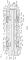
- FIG. 2 is a side view of the downhole plug of FIG. 1 that includes an embodiment of a mandrel assembly in accordance with principles disclosed herein;
- FIG. 3 is a cross-sectional view along line 3 - 3 of FIG. 2 of the downhole plug of FIG. 1 ;
- FIG. 4 is a side view of an embodiment of an inner rod of the mandrel assembly of FIG. 2 in accordance with principles disclosed herein;
- FIG. 5 is a perspective view of the inner rod of FIG. 4 ;
- FIG. 6 is a side view of the mandrel assembly of FIG. 2 ;
- FIG. 7 is a cross-sectional view along lines 7 - 7 of FIG. 6 of the mandrel assembly of FIG. 2 ;
- FIG. 8 is a flow chart of an embodiment of a method of assembling a plug for sealing a wellbore in accordance with principles disclosed herein.
- the terms “including” and “comprising” are used in an open-ended fashion, and thus should be interpreted to mean “including, but not limited to . . . .”
- the term “couple” or “couples” is intended to mean either an indirect or direct connection. Thus, if a first device couples to a second device, that connection may be through a direct connection, or through an indirect connection via other devices, components, and connections.
- the terms “axial” and “axially” generally mean along or parallel to a central axis (e.g., central axis of a body or a port), while the terms “radial” and “radially” generally mean perpendicular to the central axis.
- an axial distance refers to a distance measured along or parallel to the central axis
- a radial distance means a distance measured perpendicular to the central axis.
- wellbore 4 is a cased wellbore including a casing string 12 secured to an inner surface or wall 8 of the wellbore 4 using cement (not shown).
- casing string 12 generally includes a plurality of tubular segments coupled together via a plurality of casing collars.
- completion system 10 includes a tool string 20 disposed within wellbore 4 and suspended from a wireline 22 that extends to the surface of wellbore 4 .
- Wireline 22 comprises an armored cable and includes at least one electrical conductor for transmitting power and electrical signals between tool string 20 and the surface.
- System 10 may further include suitable surface equipment for drilling, completing, and/or operating completion system 10 such as, for example, derricks, structures, pumps, electrical/mechanical well control components, etc.
- Tool string 20 is generally configured to perforate casing string 12 to provide for fluid communication between formation 6 and wellbore 4 at predetermined locations to allow for the subsequent hydraulic fracturing of formation 6 at the predetermined locations.
- tool string 20 generally includes a cable head 24 , a casing collar locator (CCL) 26 , a direct connect sub 28 , a plurality of perforating guns 30 , a switch sub 32 , a plug-shoot firing head 34 , a setting tool 36 , and a downhole or bridge plug 100 (shown schematically in FIG. 1 ).
- Cable head 24 is the uppermost component of tool string 20 and includes an electrical connector for providing electrical signal and power communication between the wireline 22 and the other components (CCL 26 , perforating guns 30 , setting tool 36 , etc.) of tool string 20 .
- CCL 26 is coupled to a lower end of the cable head 24 and is generally configured to transmit an electrical signal to the surface via wireline 22 when CCL 26 passes through a casing collar of casing string 12 , where the transmitted signal may be recorded at the surface as a collar kick to determine the position of tool string 20 within wellbore 4 by correlating the recorded collar kick with an open hole log.
- the direct connect sub 28 is coupled to a lower end of CCL 26 and is generally configured to provide a connection between the CCL 26 and the portion of tool string 20 including the perforating guns 30 and associated tools, such as the setting tool 36 and bridge plug 100 .
- Perforating guns 30 of tool string 20 are coupled to direct connect sub 28 and are generally configured to perforate casing string 12 and provide for fluid communication between formation 6 and wellbore 4 .
- perforating guns 30 include a plurality of shaped charges that may be detonated by a signal conveyed by the wireline 22 from the surface to produce an explosive jet directed against casing string 12 .
- Perforating guns 30 may be any suitable perforation gun known in the art while still complying with the principles disclosed herein.
- perforating guns 30 may comprise a hollow steel carrier (HSC) type perforating gun, a scalloped perforating gun, or a retrievable tubing gun (RTG) type perforating gun.
- HSC hollow steel carrier
- RTG retrievable tubing gun
- gun 30 may comprise a wide variety of sizes such as, for example, 23 ⁇ 4′′, 31 ⁇ 8′′, or 33 ⁇ 8′′, wherein the above listed size designations correspond to an outer diameter of perforating guns 30 .
- Switch sub 32 of tool string 20 is coupled between the pair of perforating guns 30 and includes an electrical conductor and switch generally configured to allow for the passage of an electrical signal to the lowermost perforating gun 30 of tool string 20 .
- Tool string 20 further includes plug-shoot firing head 34 coupled to a lower end of the lowermost perforating gun 30 .
- Plug-shoot firing head 34 couples the perforating guns 30 of the tool string 20 to the setting tool 36 and bridge plug 100 , and is generally configured to pass a signal from the wireline 22 to the setting tool 36 of tool string 20 .
- Plug-shoot firing head 34 may also include mechanical and/or electrical components to fire the setting tool 36 .
- tool string 20 further includes setting tool 36 and bridge plug 100 , where setting tool 36 is coupled to a lower end of plug-shoot firing head 34 and is generally configured to set or install bridge plug 100 within casing string 12 to isolate desired segments of the wellbore 4 .
- setting tool 36 is coupled to a lower end of plug-shoot firing head 34 and is generally configured to set or install bridge plug 100 within casing string 12 to isolate desired segments of the wellbore 4 .
- an outer surface of bridge plug 100 seals against an inner surface 13 of casing string 12 to restrict fluid communication through wellbore 4 across bridge plug 100 .
- bridge plug 100 is configured to prevent fluid flow both uphole across (e.g., the annulus formed between the inner surface 13 of casing string 12 and an outer surface of bridge plug 100 ) bridge plug 100 (indicated schematically by arrow 15 in FIG. 1 ) towards the surface of wellbore 4 , and downhole across bridge plug 100 (indicated schematically by arrow 17 in FIG. 1 ) towards a lower terminal end or toe (not shown) of wellbore 4 .
- Setting tool 36 of tool string 20 may be any suitable setting tool known in the art while still complying with the principles disclosed herein.
- setting tool 36 may comprise a #10 or #20 Baker style setting tool.
- setting tool 36 may comprise a wide variety of sizes such as, for example, 1.68 in., 2.125 in., 2.75 in., 3.5 in., 3.625 in., or 4 in., wherein the above listed sizes correspond to the overall outer diameter of the tool.
- bridge plug 100 is shown in FIG. 1 as incorporated in tool string 20 , bridge plug 100 may be used in other tool strings comprising components differing from the components comprising tool string 20 .
- bridge plug 100 may be configured to sealingly engage a wall of a wellbore (e.g., the wall 8 of wellbore 4 ) rather than the inner surface of a casing string (e.g., the inner surface 13 of casing string 12 ).
- bridge plug 100 may be employed in well systems other than a completion system. For instance, in some embodiments, bridge plug 100 may be used to permanently or temporarily abandon a completed wellbore.
- bridge plug 100 has a central or longitudinal axis 105 and generally includes a mandrel assembly 102 , an engagement disk 150 , a pair of clamping members 160 A, 160 B, an elastomeric member or packer 170 , a pair of slip assemblies 200 A, 200 B, and a nose cone 220 .
- Mandrel assembly 102 of bridge plug 100 is generally configured to interface with a setting tool (e.g., setting tool 36 shown in FIG. 1 ) to assist in “setting” or actuating bridge plug 100 from a first or run-in position shown in FIGS. 2 , 3 to a second or set position.
- a setting tool e.g., setting tool 36 shown in FIG. 1
- mandrel assembly 102 of bridge plug 100 generally includes a first or outer cylindrical member or rod 104 and a second or inner cylindrical member or rod 120 positionable within outer rod 104 . As shown particularly in FIG.
- the outer rod 104 of mandrel assembly 102 has a first end 104 A, a second end 104 B opposite first end 104 A, a central bore or passage defined by a generally cylindrical inner surface 106 extending between ends 104 A, 104 B, and a generally cylindrical outer surface 108 extending between ends 104 A, 104 B.
- a first or inner surface pattern or feature 110 is positioned or formed on the inner surface 106 of outer rod 104 , as will be described further herein.
- the outer surface 108 of outer rod 104 includes an expanded diameter portion 112 extending from first end 104 A proximal upper end 104 A which forms an annular shoulder 114 .
- the expanded diameter portion 112 of outer surface 108 may include a plurality of circumferentially spaced apertures 116 (shown in FIG. 2 ) configured to receive a plurality of connecting members for coupling mandrel assembly 102 with setting tool 36 ; however, in other embodiments, outer rod 104 may not include either expanded diameter portion 112 and/or apertures 116 .
- the outer surface 108 of outer rod 104 also includes a connector 118 at second end 104 B for coupling mandrel assembly 102 with nose cone 220 .
- outer rod 104 of mandrel assembly 102 comprises a non-metallic, glass filament material; however, in other embodiments, outer rod 104 may comprise various materials.
- the outer surface 108 of outer rod 104 may include a plurality of ratchet teeth for engaging a body lock ring of downhole plug 100 configured for preventing the release of locking bridge plug 100 once plug 100 has been set by setting tool 36 .
- the inner rod 120 of mandrel assembly 102 has a first end 120 A, a second end 120 B opposite first end 120 A, and a generally cylindrical outer surface 122 extending between ends 120 A, 120 B.
- a second or outer surface pattern or feature 124 is positioned or formed on the outer surface 122 of inner rod 104 , as will be described further herein.
- the outer surface pattern 124 of inner rod 120 is configured to matingly or interlockingly engage the inner surface pattern 110 of outer rod 104 to thereby resist or prevent relative axial movement between outer rod 104 and inner rod 120 following the assembly of mandrel assembly 102 .
- the interlocking engagement between the inner surface pattern 110 of outer rod 104 and the outer surface pattern 124 of inner rod 120 is configured to prevent dislodgement of inner rod 120 from outer rod 104 as mandrel assembly 102 is exposed to elevated pressures in wellbore 4 during the completion of wellbore 4 via completion system 10 .
- outer rod 104 comprises inner surface pattern 110 and inner rod 120 comprises surface pattern 124
- outer rod 104 may not comprise an inner surface pattern and inner rod 120 may not comprise an outer surface pattern, and instead adhesion resulting from a filament winding process used to form outer rod 104 may serve to lock inner rod 120 with outer rod 104 .
- the inner surface 106 of outer rod 104 sealingly engages the outer surface 122 of inner rod 120 following the assembly of mandrel assembly 102 to prevent fluid communication across a generally cylindrical interface 125 formed between outer rod 104 and inner rod 120 .
- sealing engagement between the inner surface 106 of outer rod 104 and the outer surface 122 of inner rod 120 restricts fluid flow across interface 125 in both a first axial (e.g., parallel with central axis 105 ) direction (indicated schematically by arrow 127 in FIG. 3 ) from first a first end 125 A of interface 125 to a second end 125 B of interface 125 , and a second axial direction (indicated schematically by arrow 129 in FIG.
- the inner rod 120 of mandrel assembly 102 additionally includes a central bore or passage 126 extending from second end 120 B.
- passage 126 of inner rod 120 extends towards, but not entirely to, the first end 120 A of inner rod 120 .
- inner rod 120 of mandrel assembly 102 may be drilled or milled out by a downhole tool such that the drilled or milled passage formed by the downhole tool intercepts the central passage 126 of inner rod 120 , thereby permitting fluid flow across bridge plug 100 via central passage 126 .
- central passage 126 may assist with equalizing fluid pressure across bridge plug 100 .
- inner rod 120 of mandrel assembly 102 includes central passage 126
- inner rod 120 may not include a central or inner passage.
- Inner rod 120 may comprise a material having relatively high tensile and shear strengths.
- inner rod 120 comprises a non-metallic, composite material; however, in other embodiments, inner rod 120 may comprise fiberglass, magnesium, and other high tensile and shear strengths materials. Thus, in some embodiments, inner rod 120 may comprise a first material while outer rod 104 may comprise a second material that is different from the first material.
- Engagement disk 150 of bridge plug 100 is disposed about mandrel assembly 102 and has a first end and a second end opposite the first end.
- the first end of engagement disk 150 comprises an annular engagement surface 152 configured to engage a corresponding annular engagement surface of setting tool 36 to assist in actuating bridge plug 100 from the run-in position to the set position, as will be discussed further herein.
- engagement disk 150 includes a generally cylindrical inner surface which defines an annular shoulder 154 . In the run-in position of bridge plug 100 , annular shoulder of engagement disk 150 is disposed directly adjacent or contacts shoulder 114 the outer rod 104 of mandrel assembly 102 .
- Each clamping member 160 A, 160 B of bridge plug 100 is generally annular and is disposed about the outer rod 104 of mandrel assembly 102 .
- First clamping member 160 A is axially positioned between first slip assembly 200 A and packer 170 while second clamping member 160 B is axially positioned between packer 170 and second slip assembly 200 B.
- each clamping member 160 A, 160 B has a generally cylindrical inner surface extending between opposing ends 162 thereof that includes an inner frustoconical surface 164 .
- each clamping member 160 A, 160 B includes a generally cylindrical outer surface extending between ends 162 that includes a plurality of circumferentially spaced planar (e.g., flat) surfaces 166 .
- Each planar surface 166 extends at an angle relative to the central axis 105 of bridge plug 100 .
- friction resulting from contact between the elastomeric material comprising packer 170 and frustoconical surfaces 164 and 164 of clamping members 160 A, 160 B assists in preventing relative rotation between packer 170 and clamping members 160 A, 160 B.
- Packer 170 of bridge plug 100 is generally annular and disposed about mandrel assembly 102 between clamping members 160 A, 160 B.
- Packer 170 comprises an elastomeric material and is configured to sealingly engage the inner surface 13 of casing string 12 when bridge plug 100 is set.
- packer 170 comprises a generally cylindrical outer surface 172 extending between first and second ends of packer 170 .
- Outer surface 172 of packer 170 includes a pair of frustoconical surfaces 174 extending from each end of packer 170 , as will be discussed further herein.
- Slip assemblies 200 A, 200 B of bridge plug 100 are generally configured to engage or “bite into” the inner surface 13 of casing string 12 when bridge plug 100 is actuated into the set position to couple or affix bridge plug 100 to casing string 12 , thereby restricting relative axial movement between bridge plug 100 and casing string 12 .
- each slip assembly 200 A, 200 B comprises a plurality of circumferentially spaced arcuate slip segments 202 disposed about the outer rod 104 of mandrel assembly 102 .
- each slip segment 202 includes an inner surface extending between opposing ends 204 of slip segment 202 that includes a planar (e.g., flat) surface 206 .
- the planar surface 206 of each slip segment 202 extends at an angle relative to central axis 105 of downhole plug 105 and is configured to matingly engage one of the planar surfaces 166 of one of the clamping members 160 A, 160 B.
- planar (e.g., flat) interface formed between each corresponding planar surface 166 of clamping members 160 A, 160 B and each planar surface 206 of slip segments 202 restricts relative rotation between clamping members 160 A, 160 B and the slip segments 202 of slip assemblies 200 A, 200 B. Additionally, as will be described further herein, relative axial movement between clamping members 160 A, 160 B and slip assemblies 200 A, 200 B is configured to force the slip segments 202 of slip assemblies 200 A, 200 B radially outwards via the angled or cammed sliding contact between planar surfaces 166 of clamping members 160 A, 160 B and the planar surfaces 206 of the slip segments 202 of slip assemblies 200 A, 200 B.
- each slip segment 202 of slip assemblies 200 A, 200 B includes a generally arcuate outer surface extending between opposing ends 204 that includes a plurality of arcuate engagement members 208 .
- Engagement members 208 are configured to engage or bite into the inner surface 13 of casing string 12 when bridge plug 100 is actuated into the set position to thereby affix bridge plug 100 to casing string 12 at a desired or predetermined location.
- engagement members 208 comprise a suitable material for engaging with inner surface 13 of casing string 12 during operations.
- engagement members 208 may comprise 8620 Chrome-Nickel-Molybdenum alloy, carbon steel, tungsten carbide, cast iron, and/or tool steel.
- engagement members 208 may comprise a composite material.
- slip segments 202 may not include separate engagement members 208 .
- each slip segment 202 may comprise one or more cylindrical, ceramic engagement members or inserts configured to physically contact and couple to the inner surface of casing string 12 .
- bridge plug 100 includes a pair of slip assemblies 200 A, 200 B, in other embodiments, bridge plug 100 may include a single slip assembly or more than two slip assemblies.
- Nose cone 220 of bridge plug 100 is generally annular and is disposed about the second end 104 B of the outer rod 104 of mandrel assembly 102 .
- Nose cone 220 has a first end 220 A, a second end 220 B, a central bore or passage 222 defined by a generally cylindrical inner surface 224 extending between ends 220 A, 220 B, and a generally cylindrical outer surface 226 extending between ends 220 A, 220 B.
- the inner surface 224 of nose cone 200 includes a connector 228 that releasably or threadably couples with the connector 118 of the outer rod 104 of mandrel assembly 102 to restrict relative axial movement between mandrel assembly 102 and nose cone 220 .
- the outer surface 226 of nose cone 220 includes a plurality of axially spaced annular fins 230 .
- Fins 232 increase the surface area of outer surface 226 to facilitate the creation of turbulent fluid flow around fins 230 when bridge plug 100 is pumped through wellbore 4 along with the other components of tool string 20 to thereby increase the pressure differential in wellbore 4 between the uphole and downhole ends of bridge plug 100 .
- nose cone 220 of bridge plug 100 may not include fins 230 .
- FIGS. 4 - 7 illustrate an embodiment for forming or assembling the mandrel assembly 102 shown in FIGS. 2 , 3 .
- inner rod 120 of mandrel assembly 102 is first formed through a pultrusion process until a desired length and outer diameter of inner rod 120 is achieved.
- inner rod 120 comprises a pultruded rod.
- the outer surface 122 of inner rod 120 is machined to form outer surface pattern 124 .
- outer surface pattern 124 comprises a helical pattern 124 extending the length of inner rod 120 and comprising at least one helical recess or groove 128 and at least one helical protrusion or ridge 130 .
- a maximum outer diameter 130 D (shown in FIG. 4 ) of the helical ridge 130 of outer surface pattern 124 is greater than a maximum outer diameter 128 D (shown in FIG. 4 ) of the helical groove 128 .
- the configuration of outer surface pattern 124 may vary.
- outer surface pattern 124 may comprise one or more protrusions of various shapes formed on the outer surface 122 of inner rod 120 .
- outer surface pattern 124 comprises a protrusion which is at least partially received within the inner surface pattern 110 of outer rod 104 .
- inner surface pattern 110 may comprise at least one helical recess or groove 119 (shown in FIG. 7 ) and at least one corresponding helical protrusion or ridge 121 (shown in FIG. 7 ).
- the helical ridge 121 of inner surface pattern 110 may have a maximum inner diameter 121 D that is less than a maximum inner diameter 119 D of helical groove 119 of inner surface pattern 110 .
- the maximum inner diameter 121 D of the helical ridge 121 of inner surface pattern 110 may be less than the maximum outer diameter 130 D of the helical ridge 130 of outer surface pattern 124 .
- outer surface pattern 124 is formed on the outer surface 122 of inner rod 120 , glass filaments are uniformly wound about the outer surface 122 of inner rod 120 to thereby form outer rod 104 .
- outer rod 104 of mandrel assembly 102 is formed in this embodiment via a filament winding process until a desired outer diameter of outer rod 104 is achieved.
- the inner surface pattern 110 is formed on the inner surface 106 of outer rod 104 as outer rod 104 is formed via the filament winding process, thereby interlocking the outer surface pattern 124 of inner rod 120 into the inner surface pattern 110 formed on the inner surface 106 of outer rod 104 .
- the helical ridge 130 of the outer surface pattern 124 may be interlockingly received in the helical groove 119 of the inner surface pattern 110 .
- outer surface 108 of outer rod 104 is machined to form annular shoulder 114 and circumferentially spaced apertures 116 .
- the formation of mandrel assembly 102 is completed by forming or drilling the central passage 126 of inner rod 120 .
- inner rod 120 of mandrel assembly 102 may not include central passage 126 .
- bridge plug 100 is conveyed downhole though wellbore 4 along with the other components of tool string 20 .
- the position of tool string 20 in wellbore 4 is monitored at the surface via signals generated from CCL 26 and transmitted to the surface using wireline 22 .
- a firing or actuation signal may be transmitted from the surface to tool string 20 to actuate or fire setting tool 36 and thereby actuate bridge plug 100 from the run-in position shown in FIGS. 2 , 3 to the set position.
- setting tool 36 includes an inner member or mandrel (not shown) that moves axially relative to an outer member or housing of setting tool 36 upon the actuation of tool 36 .
- the mandrel of setting tool 36 is coupled to the outer rod 104 of the mandrel assembly 102 of bridge plug 100 such that the movement of the mandrel of setting tool 36 pulls mandrel assembly 102 uphole (e.g., towards setting tool 36 ).
- the outer member of setting tool 36 contacts engagement surface 152 of engagement disk 150 to prevent disk 150 , clamping members 160 A, 160 B, packer 170 , and slip assemblies 200 A, 200 B from travelling in concert with mandrel assembly 102 , thereby providing relative axial movement between mandrel assembly 102 and disk 150 , clamping members 160 A, 160 B, packer 170 , and slip assemblies 200 A, 200 B.
- planar surfaces 166 of clamping members 160 A, 160 B apply a radially outwards force against slip assemblies 200 A, 200 B, respectively, forcing slip segments 202 radially outward towards casing string 12 as planar surfaces 166 of clamping members 160 A, 160 B slide along the planar surfaces 204 of the slip segments 202 of slip assemblies 200 A, 200 B.
- Slip segments 202 of slip assemblies 200 A, 200 B continue to travel radially outwards until engagement members 206 contact and couple to the inner surface 13 of casing string 12 , locking bridge plug 100 to casing string 12 at the desired location in wellbore 4 .
- casing string 12 is pressure tested to confirm the sealing integrity formed between bridge plug 100 and casing string 12 .
- one or more firing signals may be transmitted from the surface to tool string 20 to fire one or more of the perforating guns 30 and thereby perforate casing string 12 at the desired location.
- setting tool 36 may be disconnected from bridge plug 100 , allowing setting tool 36 and the other components of tool string 20 to be retrieved to the surface of wellbore 4 , with bridge plug 100 remaining at the desired location in wellbore 4 .
- a lock ring of bridge plug 100 may retain bridge plug 100 in the set position once setting tool 36 is released from bridge plug 100 .
- bridge plug 100 may comprise the lowermost downhole plug installed within the casing string 12 .
- a tool may be deployed in wellbore 4 to drill out the bridge plug 100 disposed therein.
- a downhole tool may be deployed through casing string 12 to drill into and through the inner rod 120 of the mandrel assembly 102 of bridge plug 100 from first end 120 .
- the drill of the downhole tool may cut through inner rod 120 until the drill intercepts passage 126 of inner rod 120 , thereby providing fluid communication between the uphole and downhole ends of bridge plug 100 via passage 126 .
- FIG. 8 a flowchart of a method 300 of assembling a plug for sealing a wellbore is shown in FIG. 8 .
- method 300 may be practiced with the bridge plug 100 shown in FIGS. 2 - 7 .
- bridge plug 100 shown in FIGS. 2 - 7 it should be appreciated that embodiments of method 300 may be practiced with other devices.
- method 300 includes forming a first rod at method block 302 .
- method block 302 may include forming the inner rod 120 of mandrel assembly 102 through a pultrusion process until a desired length and outer diameter of inner rod 120 is achieved.
- method block 302 may also include machining a surface pattern (e.g., surface pattern 124 of inner rod 120 ) onto an outer surface of the inner rod.
- the pattern may be a helical pattern including one or more helical grooves (e.g., helical groove 128 ) and one or more helical ridges (e.g., helical ridge 130 ).
- Method 300 continues at method block 304 by forming a second rod about the first rod using a filament winding process.
- method block 304 may include uniformly winding glass filaments about the outer surface of the formed inner rod (e.g., inner rod 120 of mandrel assembly 102 ) until a desired outer diameter of the outer rod (e.g., outer rod 104 of mandrel assembly 102 ) is achieved.
- Method block 304 may also include forming a surface pattern on an inner surface of the outer rod as the outer rod is wound about the outer surface of the inner rod.
- the surface pattern may be a helical pattern including one or more helical grooves (e.g., helical groove 119 ) and one or more helical ridges (e.g., helical ridge 121 ).
- Method 300 continues at block 306 by positioning a packer about the second rod, the packer being configured to seal the wellbore in response to the plug being actuated from a first position to a second position.
- method block 306 may include positioning packer 170 about the outer surface 108 of the outer rod 104 of mandrel assembly 102 .
- method 300 may further include positioning engagement disk 150 , clamping members 160 A, 160 B, and slip assemblies 200 A, 200 B about the outer surface 108 of outer rod 104 .
- Embodiments disclosed herein include a downhole plug (e.g., bridge plug 100 ) comprising a mandrel assembly (e.g., mandrel assembly 102 ) comprising an inner rod (e.g., inner rod 120 ) and a filament wound outer rod (e.g., outer rod 104 ) that is separate and distinct from the inner rod and which is formed about the inner rod.
- a downhole plug e.g., bridge plug 100
- a mandrel assembly e.g., mandrel assembly 102
- an inner rod e.g., inner rod 120
- a filament wound outer rod e.g., outer rod 104
- the downhole plug may also include a packer (e.g., packer 170 ) disposed about the mandrel assembly, the packer configured to seal the wellbore in response to the plug being actuated from a first position to a second position, wherein the mandrel assembly is configured to apply a compressive force to the packer as the plug is actuated from the first position to the second position.
- a packer e.g., packer 170
- the costs associated with manufacturing the mandrel assembly may be minimized (e.g., relative to compression molded mandrel assemblies, etc.). For instance, the number of parts required to form the mandrel assembly may be minimized by utilizing a filament winding process. Additionally, the simplified design offered by the filament wound mandrel assemblies described herein also minimize the number of points at which a failure of the mandrel assembly may occur, thereby increasing the reliability of the mandrel assembly.
- the seal created by the filament wound mandrel assembly may enable a downhole plug incorporating the mandrel assembly to withstand relatively greater differential pressures across the plug (following setting of the plug) than other designs which may, for instance, rely on elastomeric seals (e.g., O-ring seals, etc.) for forming a seal barrier.
- elastomeric seals e.g., O-ring seals, etc.
Landscapes
- Life Sciences & Earth Sciences (AREA)
- Engineering & Computer Science (AREA)
- Geology (AREA)
- Mining & Mineral Resources (AREA)
- Physics & Mathematics (AREA)
- Environmental & Geological Engineering (AREA)
- Fluid Mechanics (AREA)
- General Life Sciences & Earth Sciences (AREA)
- Geochemistry & Mineralogy (AREA)
- Earth Drilling (AREA)
Abstract
Description
Claims (24)
Priority Applications (1)
| Application Number | Priority Date | Filing Date | Title |
|---|---|---|---|
| US17/610,008 US12146380B2 (en) | 2019-05-10 | 2020-05-08 | Mandrel assemblies for a plug and associated methods |
Applications Claiming Priority (3)
| Application Number | Priority Date | Filing Date | Title |
|---|---|---|---|
| US201962846366P | 2019-05-10 | 2019-05-10 | |
| US17/610,008 US12146380B2 (en) | 2019-05-10 | 2020-05-08 | Mandrel assemblies for a plug and associated methods |
| PCT/US2020/032221 WO2020231861A1 (en) | 2019-05-10 | 2020-05-08 | Mandrel assemblies for a plug and associated methods |
Related Parent Applications (1)
| Application Number | Title | Priority Date | Filing Date |
|---|---|---|---|
| PCT/US2020/032221 A-371-Of-International WO2020231861A1 (en) | 2019-05-10 | 2020-05-08 | Mandrel assemblies for a plug and associated methods |
Related Child Applications (1)
| Application Number | Title | Priority Date | Filing Date |
|---|---|---|---|
| US18/949,471 Continuation US20250067143A1 (en) | 2019-05-10 | 2024-11-15 | Mandrel assemblies for a plug and associated methods |
Publications (2)
| Publication Number | Publication Date |
|---|---|
| US20220228459A1 US20220228459A1 (en) | 2022-07-21 |
| US12146380B2 true US12146380B2 (en) | 2024-11-19 |
Family
ID=73288782
Family Applications (2)
| Application Number | Title | Priority Date | Filing Date |
|---|---|---|---|
| US17/610,008 Active 2040-10-13 US12146380B2 (en) | 2019-05-10 | 2020-05-08 | Mandrel assemblies for a plug and associated methods |
| US18/949,471 Pending US20250067143A1 (en) | 2019-05-10 | 2024-11-15 | Mandrel assemblies for a plug and associated methods |
Family Applications After (1)
| Application Number | Title | Priority Date | Filing Date |
|---|---|---|---|
| US18/949,471 Pending US20250067143A1 (en) | 2019-05-10 | 2024-11-15 | Mandrel assemblies for a plug and associated methods |
Country Status (2)
| Country | Link |
|---|---|
| US (2) | US12146380B2 (en) |
| WO (1) | WO2020231861A1 (en) |
Cited By (1)
| Publication number | Priority date | Publication date | Assignee | Title |
|---|---|---|---|---|
| US20250067143A1 (en) * | 2019-05-10 | 2025-02-27 | G&H Diversified Manufacturing Lp | Mandrel assemblies for a plug and associated methods |
Families Citing this family (1)
| Publication number | Priority date | Publication date | Assignee | Title |
|---|---|---|---|---|
| WO2019071024A1 (en) * | 2017-10-06 | 2019-04-11 | G&H Diversified Manufacturing Lp | Systems and methods for sealing a wellbore |
Citations (20)
| Publication number | Priority date | Publication date | Assignee | Title |
|---|---|---|---|---|
| US20030226660A1 (en) * | 2002-06-10 | 2003-12-11 | Winslow Donald W. | Expandable retaining shoe |
| US20070029080A1 (en) | 2000-07-07 | 2007-02-08 | Moyes Peter B | Deformable member |
| US20080060821A1 (en) * | 2006-09-13 | 2008-03-13 | Halliburton Energy Services, Inc. | Packer element retaining system |
| US7740079B2 (en) * | 2007-08-16 | 2010-06-22 | Halliburton Energy Services, Inc. | Fracturing plug convertible to a bridge plug |
| US20110290473A1 (en) | 2009-04-21 | 2011-12-01 | Frazier W Lynn | Configurable inserts for downhole plugs |
| US8079413B2 (en) * | 2008-12-23 | 2011-12-20 | W. Lynn Frazier | Bottom set downhole plug |
| US20120061105A1 (en) * | 2010-09-14 | 2012-03-15 | Halliburton Energy Services, Inc. | Single piece packer extrusion limiter ring |
| WO2012045168A1 (en) | 2010-10-06 | 2012-04-12 | Packers Plus Energy Services Inc. | Wellbore packer back-up ring assembly, packer and method |
| US20120125642A1 (en) * | 2010-11-23 | 2012-05-24 | Chenault Louis W | Convertible multi-function downhole isolation tool and related methods |
| US8205671B1 (en) * | 2009-12-04 | 2012-06-26 | Branton Tools L.L.C. | Downhole bridge plug or packer assemblies |
| US8596347B2 (en) * | 2010-10-21 | 2013-12-03 | Halliburton Energy Services, Inc. | Drillable slip with buttons and cast iron wickers |
| US20140045731A1 (en) * | 2009-10-02 | 2014-02-13 | Schlumberger Technology Corporation | Equipment and Methods for Preparing Curved Fibers |
| US8839855B1 (en) * | 2012-02-22 | 2014-09-23 | McClinton Energy Group, LLC | Modular changeable fractionation plug |
| US8887818B1 (en) * | 2011-11-02 | 2014-11-18 | Diamondback Industries, Inc. | Composite frac plug |
| US9845658B1 (en) | 2015-04-17 | 2017-12-19 | Albany International Corp. | Lightweight, easily drillable or millable slip for composite frac, bridge and drop ball plugs |
| WO2018009487A1 (en) * | 2016-07-05 | 2018-01-11 | Downhole Technology, Llc | Downhole tool and method of use |
| US20180202257A1 (en) | 2011-08-22 | 2018-07-19 | Downhole Technology, Llc | Mandrel for a Downhole Tool |
| US20190352999A1 (en) * | 2018-05-16 | 2019-11-21 | Nine Downhole Technologies, Llc | Filament-Reinforced Composite Material with Load-Aligned Filament Windings |
| US20220228459A1 (en) * | 2019-05-10 | 2022-07-21 | G&H Diversified Manufacturing Lp | Mandrel assemblies for a plug and associated methods |
| US11396787B2 (en) * | 2019-02-11 | 2022-07-26 | Innovex Downhole Solutions, Inc. | Downhole tool with ball-in-place setting assembly and asymmetric sleeve |
-
2020
- 2020-05-08 US US17/610,008 patent/US12146380B2/en active Active
- 2020-05-08 WO PCT/US2020/032221 patent/WO2020231861A1/en not_active Ceased
-
2024
- 2024-11-15 US US18/949,471 patent/US20250067143A1/en active Pending
Patent Citations (21)
| Publication number | Priority date | Publication date | Assignee | Title |
|---|---|---|---|---|
| US20070029080A1 (en) | 2000-07-07 | 2007-02-08 | Moyes Peter B | Deformable member |
| US20030226660A1 (en) * | 2002-06-10 | 2003-12-11 | Winslow Donald W. | Expandable retaining shoe |
| US20080060821A1 (en) * | 2006-09-13 | 2008-03-13 | Halliburton Energy Services, Inc. | Packer element retaining system |
| US7740079B2 (en) * | 2007-08-16 | 2010-06-22 | Halliburton Energy Services, Inc. | Fracturing plug convertible to a bridge plug |
| US8079413B2 (en) * | 2008-12-23 | 2011-12-20 | W. Lynn Frazier | Bottom set downhole plug |
| US20110290473A1 (en) | 2009-04-21 | 2011-12-01 | Frazier W Lynn | Configurable inserts for downhole plugs |
| US20140045731A1 (en) * | 2009-10-02 | 2014-02-13 | Schlumberger Technology Corporation | Equipment and Methods for Preparing Curved Fibers |
| US8205671B1 (en) * | 2009-12-04 | 2012-06-26 | Branton Tools L.L.C. | Downhole bridge plug or packer assemblies |
| US20120061105A1 (en) * | 2010-09-14 | 2012-03-15 | Halliburton Energy Services, Inc. | Single piece packer extrusion limiter ring |
| WO2012045168A1 (en) | 2010-10-06 | 2012-04-12 | Packers Plus Energy Services Inc. | Wellbore packer back-up ring assembly, packer and method |
| US8596347B2 (en) * | 2010-10-21 | 2013-12-03 | Halliburton Energy Services, Inc. | Drillable slip with buttons and cast iron wickers |
| US20120125642A1 (en) * | 2010-11-23 | 2012-05-24 | Chenault Louis W | Convertible multi-function downhole isolation tool and related methods |
| US20180202257A1 (en) | 2011-08-22 | 2018-07-19 | Downhole Technology, Llc | Mandrel for a Downhole Tool |
| US8887818B1 (en) * | 2011-11-02 | 2014-11-18 | Diamondback Industries, Inc. | Composite frac plug |
| US8839855B1 (en) * | 2012-02-22 | 2014-09-23 | McClinton Energy Group, LLC | Modular changeable fractionation plug |
| US9845658B1 (en) | 2015-04-17 | 2017-12-19 | Albany International Corp. | Lightweight, easily drillable or millable slip for composite frac, bridge and drop ball plugs |
| WO2018009487A1 (en) * | 2016-07-05 | 2018-01-11 | Downhole Technology, Llc | Downhole tool and method of use |
| US20180142096A1 (en) * | 2016-07-05 | 2018-05-24 | Downhole Technology, Llc | Composition of matter and use thereof |
| US20190352999A1 (en) * | 2018-05-16 | 2019-11-21 | Nine Downhole Technologies, Llc | Filament-Reinforced Composite Material with Load-Aligned Filament Windings |
| US11396787B2 (en) * | 2019-02-11 | 2022-07-26 | Innovex Downhole Solutions, Inc. | Downhole tool with ball-in-place setting assembly and asymmetric sleeve |
| US20220228459A1 (en) * | 2019-05-10 | 2022-07-21 | G&H Diversified Manufacturing Lp | Mandrel assemblies for a plug and associated methods |
Non-Patent Citations (1)
| Title |
|---|
| International Search Report and Written Opinion dated Aug. 25, 2020, for Application No. PCT/US2020/032221. |
Cited By (1)
| Publication number | Priority date | Publication date | Assignee | Title |
|---|---|---|---|---|
| US20250067143A1 (en) * | 2019-05-10 | 2025-02-27 | G&H Diversified Manufacturing Lp | Mandrel assemblies for a plug and associated methods |
Also Published As
| Publication number | Publication date |
|---|---|
| WO2020231861A1 (en) | 2020-11-19 |
| US20220228459A1 (en) | 2022-07-21 |
| US20250067143A1 (en) | 2025-02-27 |
Similar Documents
| Publication | Publication Date | Title |
|---|---|---|
| US12385351B2 (en) | Systems and methods for sealing a wellbore | |
| US10934795B2 (en) | Systems and methods for setting a downhole plug | |
| US11313200B2 (en) | Anti-extrusion slip assemblies for a downhole sealing device | |
| US11047188B2 (en) | Power cartridges for setting tools | |
| US9835003B2 (en) | Frac plug | |
| US20250067143A1 (en) | Mandrel assemblies for a plug and associated methods | |
| WO2017151384A1 (en) | Frac plug | |
| US11434715B2 (en) | Frac plug with collapsible plug body having integral wedge and slip elements | |
| US11993984B2 (en) | Downhole coupling mechanism | |
| AU2016268394B2 (en) | Multi-function dart | |
| EP2412921B1 (en) | Apparatus and method for depth referencing downhole tubular strings | |
| WO2009142957A1 (en) | System to perforate a cemented liner having lines or tools outside the liner | |
| EP3049606B1 (en) | Liner hanger setting tool and method for use of same | |
| US12540525B2 (en) | Hybrid dissolvable plugs for sealing downhole casing strings | |
| US10526876B2 (en) | Method and system for hydraulic communication with target well from relief well | |
| US20210054705A1 (en) | Methods and systems for a sub with internal components that shift to form a seat allowing an object to land on the seat and form a seal | |
| US12492601B2 (en) | Anti-preset liner hanger systems | |
| AU2019240582A1 (en) | A downhole coupling mechanism |
Legal Events
| Date | Code | Title | Description |
|---|---|---|---|
| AS | Assignment |
Owner name: G&H DIVERSIFIED MANUFACTURING LP, TEXAS Free format text: ASSIGNMENT OF ASSIGNORS INTEREST;ASSIGNORS:LEE, TIMMOTHY ALAIN;MAGILL, JOSHUA;SIGNING DATES FROM 20190523 TO 20190528;REEL/FRAME:058063/0539 Owner name: G&H DIVERSIFIED MANUFACTURING LP, TEXAS Free format text: ASSIGNMENT OF ASSIGNOR'S INTEREST;ASSIGNORS:LEE, TIMMOTHY ALAIN;MAGILL, JOSHUA;SIGNING DATES FROM 20190523 TO 20190528;REEL/FRAME:058063/0539 |
|
| FEPP | Fee payment procedure |
Free format text: ENTITY STATUS SET TO UNDISCOUNTED (ORIGINAL EVENT CODE: BIG.); ENTITY STATUS OF PATENT OWNER: SMALL ENTITY |
|
| FEPP | Fee payment procedure |
Free format text: ENTITY STATUS SET TO SMALL (ORIGINAL EVENT CODE: SMAL); ENTITY STATUS OF PATENT OWNER: SMALL ENTITY |
|
| STPP | Information on status: patent application and granting procedure in general |
Free format text: DOCKETED NEW CASE - READY FOR EXAMINATION |
|
| STPP | Information on status: patent application and granting procedure in general |
Free format text: NON FINAL ACTION MAILED |
|
| STPP | Information on status: patent application and granting procedure in general |
Free format text: RESPONSE TO NON-FINAL OFFICE ACTION ENTERED AND FORWARDED TO EXAMINER |
|
| STPP | Information on status: patent application and granting procedure in general |
Free format text: FINAL REJECTION MAILED |
|
| STPP | Information on status: patent application and granting procedure in general |
Free format text: DOCKETED NEW CASE - READY FOR EXAMINATION |
|
| STPP | Information on status: patent application and granting procedure in general |
Free format text: NON FINAL ACTION MAILED |
|
| STPP | Information on status: patent application and granting procedure in general |
Free format text: RESPONSE TO NON-FINAL OFFICE ACTION ENTERED AND FORWARDED TO EXAMINER |
|
| STPP | Information on status: patent application and granting procedure in general |
Free format text: NOTICE OF ALLOWANCE MAILED -- APPLICATION RECEIVED IN OFFICE OF PUBLICATIONS |
|
| STPP | Information on status: patent application and granting procedure in general |
Free format text: PUBLICATIONS -- ISSUE FEE PAYMENT RECEIVED |
|
| STPP | Information on status: patent application and granting procedure in general |
Free format text: PUBLICATIONS -- ISSUE FEE PAYMENT VERIFIED |
|
| STCF | Information on status: patent grant |
Free format text: PATENTED CASE |
|
| AS | Assignment |
Owner name: PNC BANK, NATIONAL ASSOCIATION, PENNSYLVANIA Free format text: SECURITY INTEREST;ASSIGNOR:G & H DIVERSIFIED MFG., L.P.;REEL/FRAME:071758/0583 Effective date: 20250620 |