US12145811B2 - Systems and methods for controlling the disgorging of objects in containers by vibratory motion - Google Patents
Systems and methods for controlling the disgorging of objects in containers by vibratory motion Download PDFInfo
- Publication number
- US12145811B2 US12145811B2 US17/583,528 US202217583528A US12145811B2 US 12145811 B2 US12145811 B2 US 12145811B2 US 202217583528 A US202217583528 A US 202217583528A US 12145811 B2 US12145811 B2 US 12145811B2
- Authority
- US
- United States
- Prior art keywords
- container
- objects
- angle
- disgorgement
- movement
- Prior art date
- Legal status (The legal status is an assumption and is not a legal conclusion. Google has not performed a legal analysis and makes no representation as to the accuracy of the status listed.)
- Active, expires
Links
Images


Classifications
-
- B—PERFORMING OPERATIONS; TRANSPORTING
- B65—CONVEYING; PACKING; STORING; HANDLING THIN OR FILAMENTARY MATERIAL
- B65G—TRANSPORT OR STORAGE DEVICES, e.g. CONVEYORS FOR LOADING OR TIPPING, SHOP CONVEYOR SYSTEMS OR PNEUMATIC TUBE CONVEYORS
- B65G65/00—Loading or unloading
- B65G65/30—Methods or devices for filling or emptying bunkers, hoppers, tanks, or like containers, of interest apart from their use in particular chemical or physical processes or their application in particular machines, e.g. not covered by a single other subclass
- B65G65/34—Emptying devices
-
- B—PERFORMING OPERATIONS; TRANSPORTING
- B65—CONVEYING; PACKING; STORING; HANDLING THIN OR FILAMENTARY MATERIAL
- B65G—TRANSPORT OR STORAGE DEVICES, e.g. CONVEYORS FOR LOADING OR TIPPING, SHOP CONVEYOR SYSTEMS OR PNEUMATIC TUBE CONVEYORS
- B65G65/00—Loading or unloading
- B65G65/23—Devices for tilting and emptying of containers
-
- B—PERFORMING OPERATIONS; TRANSPORTING
- B65—CONVEYING; PACKING; STORING; HANDLING THIN OR FILAMENTARY MATERIAL
- B65B—MACHINES, APPARATUS OR DEVICES FOR, OR METHODS OF, PACKAGING ARTICLES OR MATERIALS; UNPACKING
- B65B69/00—Unpacking of articles or materials, not otherwise provided for
- B65B69/005—Unpacking of articles or materials, not otherwise provided for by expelling contents, e.g. by squeezing the container
-
- B—PERFORMING OPERATIONS; TRANSPORTING
- B65—CONVEYING; PACKING; STORING; HANDLING THIN OR FILAMENTARY MATERIAL
- B65G—TRANSPORT OR STORAGE DEVICES, e.g. CONVEYORS FOR LOADING OR TIPPING, SHOP CONVEYOR SYSTEMS OR PNEUMATIC TUBE CONVEYORS
- B65G43/00—Control devices, e.g. for safety, warning or fault-correcting
- B65G43/08—Control devices operated by article or material being fed, conveyed or discharged
-
- B—PERFORMING OPERATIONS; TRANSPORTING
- B65—CONVEYING; PACKING; STORING; HANDLING THIN OR FILAMENTARY MATERIAL
- B65G—TRANSPORT OR STORAGE DEVICES, e.g. CONVEYORS FOR LOADING OR TIPPING, SHOP CONVEYOR SYSTEMS OR PNEUMATIC TUBE CONVEYORS
- B65G47/00—Article or material-handling devices associated with conveyors; Methods employing such devices
- B65G47/02—Devices for feeding articles or materials to conveyors
- B65G47/04—Devices for feeding articles or materials to conveyors for feeding articles
- B65G47/12—Devices for feeding articles or materials to conveyors for feeding articles from disorderly-arranged article piles or from loose assemblages of articles
- B65G47/14—Devices for feeding articles or materials to conveyors for feeding articles from disorderly-arranged article piles or from loose assemblages of articles arranging or orientating the articles by mechanical or pneumatic means during feeding
- B65G47/1407—Devices for feeding articles or materials to conveyors for feeding articles from disorderly-arranged article piles or from loose assemblages of articles arranging or orientating the articles by mechanical or pneumatic means during feeding the articles being fed from a container, e.g. a bowl
- B65G47/1414—Devices for feeding articles or materials to conveyors for feeding articles from disorderly-arranged article piles or from loose assemblages of articles arranging or orientating the articles by mechanical or pneumatic means during feeding the articles being fed from a container, e.g. a bowl by means of movement of at least the whole wall of the container
- B65G47/1421—Vibratory movement
-
- B—PERFORMING OPERATIONS; TRANSPORTING
- B65—CONVEYING; PACKING; STORING; HANDLING THIN OR FILAMENTARY MATERIAL
- B65G—TRANSPORT OR STORAGE DEVICES, e.g. CONVEYORS FOR LOADING OR TIPPING, SHOP CONVEYOR SYSTEMS OR PNEUMATIC TUBE CONVEYORS
- B65G47/00—Article or material-handling devices associated with conveyors; Methods employing such devices
- B65G47/34—Devices for discharging articles or materials from conveyor
- B65G47/42—Devices for discharging articles or materials from conveyor operated by article or material being conveyed and discharged
-
- B—PERFORMING OPERATIONS; TRANSPORTING
- B65—CONVEYING; PACKING; STORING; HANDLING THIN OR FILAMENTARY MATERIAL
- B65G—TRANSPORT OR STORAGE DEVICES, e.g. CONVEYORS FOR LOADING OR TIPPING, SHOP CONVEYOR SYSTEMS OR PNEUMATIC TUBE CONVEYORS
- B65G2203/00—Indexing code relating to control or detection of the articles or the load carriers during conveying
- B65G2203/02—Control or detection
- B65G2203/0208—Control or detection relating to the transported articles
- B65G2203/0225—Orientation of the article
-
- B—PERFORMING OPERATIONS; TRANSPORTING
- B65—CONVEYING; PACKING; STORING; HANDLING THIN OR FILAMENTARY MATERIAL
- B65G—TRANSPORT OR STORAGE DEVICES, e.g. CONVEYORS FOR LOADING OR TIPPING, SHOP CONVEYOR SYSTEMS OR PNEUMATIC TUBE CONVEYORS
- B65G2203/00—Indexing code relating to control or detection of the articles or the load carriers during conveying
- B65G2203/04—Detection means
- B65G2203/041—Camera
Definitions
- the invention generally relates to programmable motion control systems whose task is to move objects from one location to another, and relates in particular to programmable motion control systems intended for use in environments requiring, for example, that a variety of objects (e.g., products, articles, parcels, packages, etc.) be sorted and/or distributed to any of several output destinations.
- objects e.g., products, articles, parcels, packages, etc.
- the invention relates, in particular, to automated material handling applications in which containers of objects of varying sizes and shapes need to be emptied of their contents and then processed in an orderly fashion.
- a container may be a bulk container also known as a Gaylord container, for example, which might contain boxes or packages of varying sizes.
- Frequently such kinds of bulk containers are emptied by human workers that simply tip them over to empty the contents. If the contents of the bulk container are fragile, then this approach is often inadequate. As the bulk container is tipped over, it creates an avalanche of goods that can crush items at the bottom of the avalanche.
- each object After being removed from such a container, each object must then be processed and distributed to a correct destination location, as determined by identification information associated with the object, which is commonly determined by a label printed on the object or on a sticker on the object. Routes to the destination location may involve routing the object to an intermediate location that may take many forms, such as a bag or a bin.
- a human sorter picks an object from an incoming bin, finds a barcode on the object, scans the barcode with a handheld barcode scanner, determines from the scanned barcode the appropriate bin or shelf location for the article, and then places the article in the so-determined bin or shelf location where all objects for that order have been defined to belong.
- Automated systems for order fulfillment have also been proposed. See for example, U.S. Patent Application Publication No. 2014/0244026, which discloses the use of a robotic arm together with an arcuate structure that is movable to within reach of the robotic arm.
- An induction element or elements e.g., a conveyor, a tilt tray, or manually movable bins
- transport the objects to the desired destination or further processing station which may be a bin, a chute, a bag or a conveyor etc.
- human workers or automated systems may retrieve objects from a disorganized grouping on objects, and sort each object into a collection bin based on a set of given heuristics. For instance, all objects of like type might go to a collection bin, or all objects in a single customer order, or all objects destined for the same shipping destination, etc.
- the human workers or automated systems are required to receive objects and to move each to their assigned collection bin. If the number of different types of input (received) objects is large, a large number of collection bins is required.
- the invention provides a system for controlling the disgorging of objects.
- the system includes a container system including a container for containing objects, rotation means for rotating the container to a disgorgement angle, and movement means for moving at least a portion of the container system in a repetitious manner with a net zero distance of travel of the at least the portion of container system such that the objects are disgorged from the container at a controlled rate of disgorgement.
- the invention provides a system for controlling the disgorging of objects from a container.
- the system includes a container receiving system for receiving the container of objects at a lift and rotate mechanism, said lift and rotate mechanism being adapted to lift the container and to rotate the container to a disgorgement angle, and movement means for moving at least a portion of the lift and rotate mechanism in a repetitious manner with a net zero distance of travel of the at least the portion of lift and rotate mechanism such that objects are disgorged from the container at a controlled rate of disgorgement.
- the invention provides a method for controlling the disgorging of objects.
- the method includes providing a container system including a container for containing objects, rotating the container to a disgorgement angle, and moving at least a portion of the container system in a repetitious manner with a net zero distance of travel of the at least the portion of the container such that said objects are disgorged from the container at a controlled rate of disgorgement.
- FIG. 1 shows an illustrative diagrammatic view of disgorgement system in accordance with an embodiment of the present invention
- FIG. 2 shows an illustrative diagrammatic view of the system of FIG. 1 with the container engaged by the container handling system;
- FIG. 3 shows an illustrative diagrammatic view of the system of FIG. 1 with the container handling system lifting the container;
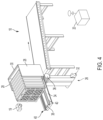
- FIG. 4 shows an illustrative diagrammatic view of the system of FIG. 1 with the container handling system tilting the container onto a conveyor system;
- FIGS. 5 A and 5 B show illustrative diagrammatic side views of a vibration actuator for use in a system in accordance with an aspect of the invention that includes a linear actuator;
- FIGS. 6 A and 6 B show illustrative diagrammatic isometric views of the vibration actuator of FIGS. 5 A and 5 B showing the central actuator;
- FIGS. 7 A- 7 C show illustrative graphical representations of vibratory motion patterns in a system in accordance with various aspects of the invention
- FIG. 8 shows an illustrative graphical representation of vibration vs frequency of a container in accordance with an aspect of the invention
- FIG. 9 shows an illustrative diagrammatic view of the system of FIG. 1 with the container handling system controlling disgorgement of objects from the container onto the conveyor system;
- FIGS. 10 A- 10 D show illustrative diagrammatic side views of a vibration actuator for use in a system in accordance with an aspect of the invention that includes a rotary actuator;
- FIGS. 11 A- 11 D show illustrative diagrammatic isometric views of the vibration actuator of FIGS. 10 A- 10 D showing the central actuator;
- FIGS. 12 A- 12 D show illustrative diagrammatic side views of a vibration actuator for use in a system in accordance with an aspect of the invention that includes a cam actuator;
- FIGS. 13 A- 13 D show illustrative diagrammatic isometric views of the vibration actuator of FIGS. 12 A- 12 D showing the central actuator;
- FIGS. 14 A and 14 B show illustrative diagrammatic side views of a vibration actuator for use in a system in accordance with an aspect of the invention that includes a vertical actuator;
- FIGS. 15 A and 15 B show illustrative diagrammatic isometric views of the vibration actuator of FIGS. 14 A and 14 B showing the central actuator;
- FIG. 16 shows an illustrative diagrammatic view of a container handling system in accordance with a further aspect of the invention that includes a force torque sensor and a perception system;
- FIG. 17 shows an illustrative diagrammatic view of the perception system of FIG. 16 ;
- FIG. 18 shows an illustrative diagrammatic view of the container handling system of FIG. 16 disgorging objects onto a conveyor system
- FIGS. 19 A- 19 C show illustrative diagrammatic views of a disgorgement process in accordance with an aspect of the invention
- FIG. 20 shows an illustrative diagrammatic view of a container handling system in accordance with a further aspect of the invention that includes a hinged top with separately hinged sections;
- FIG. 21 shows an illustrative diagrammatic view of a container handling system in accordance with a further aspect of the invention that includes a motion controlled chute;
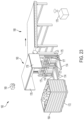
- FIG. 22 shows an illustrative diagrammatic side view of the system of FIG. 21 disgorging objects onto a conveyor system
- FIG. 23 shows an illustrative diagrammatic view of a container handling system in accordance with a further aspect of the invention that includes accommodates a double wide container.
- the invention provides an approach to safely disgorging contents of objects from containers as a stream of objects, with less damage than a simple tipping approach.
- the invention provides a system that empties a bulk container filled with packages by tipping the container over but then vibrating the restrained container back and forth. The container is tipped to a slope before which the packages slide out uncontrollably—as used herein, the slope at which sliding starts, is the slope of incipient slip, and the angle is referred to as the incipient angle.
- the tipper vibrates in an oscillatory motion whose net effect in the lateral direction is a back and forth in the direction of the sliding.
- the action of vibrating induces controllable slipping.
- sliding motion stops because the kinetic friction rapidly dampens the motion to resting.
- the tipper vibrates, it imparts a velocity and momentum on the packages that causes them to momentarily exceed the static friction forces that keep the packages from sliding.
- the invention provides a strategy and mechanism for emptying containers, and combines tipping and shaking to empty the contents of the container.
- the system firmly retains a container so that it may be both tipped and shaken. The firmness provides that there is transmission of a vibratory motion to the container itself, and that in particular the surface of the interior of the container vibrates underneath the contained items.
- the system may also automatically adjust to the size of the container and/or the objects within the container as discussed below.
- FIG. 1 shows a processing system 10 that includes a container system 12 that may receive a container 14 containing objects 16 , and lift and dump the objects onto a conveyor system 18 under the control of one or more processing systems 20 .
- the container 14 may include a pallet base 22 that may receive lift forks tongs 24 of a container handling system 26 of an aspect of the present invention.
- the lift fork tongs 24 are maintained slightly off the floor (ground) so that the pallet base 22 may be slid onto the tongs 24 .
- the tongs 24 may be angled on the bottom such that the free ends of the tongs rest above the floor.
- the thickest part of the lift fork tongs 24 may be the same thickness as (or slightly larger than) the opening within the pallet base 22 into which the tongs 24 are inserted.
- the container handling system 26 includes guide sides 28 as well as a hinged top 30 .
- FIG. 2 shows the container 14 having been engaged onto the tongs 24
- FIG. 3 shows the container being lifted by the container handling system 26 .
- the container handling system 26 includes a base 32 and a lift arm 34 .
- the lift arm 34 is also rotatable by motor 36 to tip the container such that one side is horizontal.
- the hinged top 30 may either hang straight down, or in certain aspects, may be actively closed to ensure that objects remain contained within the container at this time.
- the motor 36 may further include a force torque sensor, whereby the weight of the contents of the container may be determined.
- the tongs 24 are mounted to and moved up and down by a central actuator 38 that includes lift sections 25 that lift the tongs 24 , as well as a vibration actuator 40 that selectively causes the central actuator 38 to vibrate with respect to the remaining portions of the container handling system 26 .
- the lift sections 25 further include load cells or force torque sensors 23 (shown in FIG. 1 ), that, when the container is lifted to be horizontal as shown in FIG. 4 , may be used to determine the total weight of the objects 16 as well as the container 14 and pallet base 22 . Knowing weight of the container 14 and the pallet base 22 , permits the system to determine the weight of the total set of the objects 16 within the container 14 .
- FIGS. 5 A and 5 B show side views of a vibration actuator 40 in accordance with an aspect of the present invention
- FIGS. 6 A and 6 B show isometric views of the vibration actuator 40 and the lift arm 34
- the vibration actuator 40 includes a bracket 44 that is attached to the central actuator 38 , as well as a piston or solenoid 42 that acts on the bracket 44 , and an optional return spring 46 that urges the piston or solenoid 42 to a return position.
- the piston or solenoid 42 may be reversibly activated.
- the vibration actuators may be employed in unison to provide a specific vibration pattern as discussed below. Additionally, the pattern (or two or more patterns) may be swept through a range of frequencies, while the system monitors (e.g., via a detection system 19 such as a camera, or via the load cells or force torque sensors 23 ) vibratory motion of the container. In this way, the frequency at which the container appears to be most resonant may be determined. This information may provide significant information regarding the container's contents, including for example, the total weight of and/or the number of objects within the container.
- FIGS. 7 A- 7 C show different representations of vibration motion patterns of the bracket 44 (and therefore the central actuator 38 ) over time.
- the piston or solenoid 42 acts against the bracket 44 as shown at 50
- the return spring 46 acts against the bracket 44 as shown at 52 .
- the net distance of movement of the bracket is zero, but the bracket is effectively vibrated, which causes the central actuator 38 and the container to vibrate, which in turn causes the objects 16 within the container to slide.
- the vibratory motion may have a roughly 50% duty cycle as shown in FIG. 7 A .
- FIG. 7 B shows at 54 the movement of the bracket acted upon by the piston or solenoid 42 , and shows at 56 the movement of the bracket acted upon by the return spring 46 .
- the duty cycle of the movement of the piston or solenoid is much less than 50% (is about 16.5%).
- FIG. 7 C shows at 58 the movement of the bracket acted upon by the piston or solenoid 42 , and shows at 59 the movement of the bracket acted upon by the return spring 46 .
- the duty cycle of the movement of the piston or solenoid here is about 7.5%.
- a potential effect of varying the duty cycle in such a way is that the quick motion, when combined with a much slower return motion, may serve to cause objects within the container to move within the container in either direction.
- the objects may move with the container when moved slowly, but may slip with respect to the container when the container is moved quickly. This principal may be used to walk objects either out of the container, or to retain them within the container to slow their disgorgement.
- FIG. 8 shows a graphical illustration of vibration vs frequency of a container of objects in a system in accordance with aspects of the present invention.
- the relationship is shown at 53 , and as shown at 55 , a peak vibration of the container may exist at a frequency F(c) at which the container of objects appears to vibrate the most significantly (V peak ). Again, this information may be used to determine characteristics of the objects within the container, for example, total weight and/or total number of objects.
- the container handling system 26 including the base 32 and the lift arm 34 , may then be used to lift the container past horizontal. Again, not only does the lift arm 34 lift the container upward (as shown in FIG. 3 ), the lift arm 34 is also rotatable by motor 36 to tip the container. When this happens, the hinged top swings open (or is actuated to open), and the pallet base 22 engages the bottom sides of the tongs 24 and is thereby held by the tongs 24 . The container 14 is secured to the pallet base 22 .
- the inner surface of the guide sides 28 may include stops 15 (e.g., on the insides of the guide sides as shown in FIG. 3 ) against which the container may rest when turned over. Again, the lifting motion and the rotating motion may be powered by hydraulic actuators or electric motors.
- FIGS. 10 A- 10 D show side views of a vibration actuator 60 in accordance with another aspect of the present invention
- FIGS. 11 A- 11 D show isometric views of the vibration actuator 60 and the lift arm 34 .
- the vibration actuator 60 may be used in place of the vibration actuator 40 of the prior aspect of the invention.
- the vibration actuator 60 includes a bracket 64 that is attached to the central actuator 38 , as well as a rotating drive 62 that is attached to a linkage 66 that acts on the bracket 64 . As the drive 62 rotates, the linkage 66 causes the bracket 64 (and thereby the central actuator 38 ) to move in a vibratory motion as discussed above, though the displacement over time would be more sinusoidal.
- FIGS. 12 A- 12 D show side views of a vibration actuator 70 in accordance with another aspect of the present invention
- FIGS. 13 A- 13 D show isometric views of the vibration actuator 70 and the lift arm 34 .
- the vibration actuator 70 may be used in place of the vibration actuator 40 of the aspect of FIGS. 1 - 6 B .
- the vibration actuator 70 includes a rotating cam mechanism 72 that is attached with brackets 74 , 76 to the central actuator 38 .
- the vibration actuator 70 may further include springs 78 , 79 that urge the brackets toward a central position against the action of the cam. As the cam 72 rotates, the brackets 74 , 76 (and thereby the central actuator 38 ) are urged to the left ( FIG. 12 B ), then to the right ( FIG. 12 D ), which causes the central actuator 38 to move in a vibratory motion as discussed above, with a sinusoidal displacement over time.
- the container handling system may include one or more (e.g., two or four) vibration actuators 40 , 60 , 70 .
- the system shown in FIG. 4 may include a vibration actuator on either side of the lift arm 34 , and the two or more vibration actuators may operate in unison under the control of the one or more processing systems 20 .
- the system may additionally include a vertical vibration actuator 80 as shown in FIGS. 14 A- 15 B .
- FIGS. 14 A and 14 B show side views of a vertical vibration actuator 80 in accordance with an aspect of the present invention
- FIGS. 15 A and 15 B show isometric views of the vertical vibration actuator 80 and the lift arm 34 .
- the vertical vibration actuator 80 includes a bracket 84 that is attached to the central actuator 38 (having a bottom 39 ), as well as a piston or solenoid 82 that acts on the bracket 84 , and an optional return spring 86 that urges the piston or solenoid 82 to a return position similar to the vibration actuator 40 of FIGS. 5 A- 6 B .
- the central actuator 38 is shown lifted in FIGS.
- FIGS. 14 A- 15 B may include a vertical vibration actuator on either side of the lift arm 34 ; the two (or more) vertical vibration actuators may operate in unison under the control of the one or more processing systems 20 .
- Systems of the invention may provide either or both horizontal and vertical motion, and when combined may be tuned to hop objects out of the container.
- the system may tip to an angle that is any of: 1) sensed by shifting load inside the container with force sensors, visual sensors, or 3D sensors, or 2) learned automatically for a given application, by recording the angles that are too great where too many objects exit the container, or too little where nothing exits the container even when shook, and then executes binary search or other optimization to find the best angle, or 3) uses a pre-determined slope of incipient slip tuned by hand for a given application.
- FIG. 16 shows a container handling system 90 for use in a processing system 10 of FIGS. 1 - 4 that includes lift fork tongs 94 and a base 96 .
- the system 96 includes a lift arm 98 that includes a central actuator 100 as well as a control motor 102 that includes a force torque sensor for determining a weight of the container.
- the lift fork tongs 94 are attached to lift sections 95 that further include load cells or force torque sensors 93 , that, when the container is lifted to be horizontal (e.g., as shown in FIG. 4 ), may be used to determine the total weight of the objects as well as the container and pallet base.
- the system 96 further includes guide sides 104 and a hinged top 106 , as well as an array 108 of sensors, cameras and/or detectors. As shown in FIG. 17 , for example, the array 108 may include lights 110 , cameras 112 , and/or other motion sensors 114 (e.g., motion detectors), and these systems may be used together with the one or more processors 130 to detect any movement within the container.
- the array 108 may include lights 110 , cameras 112 , and/or other motion sensors 114 (e.g., motion detectors), and these systems may be used together with the one or more processors 130 to detect any movement within the container.
- the system may rotate the container from the position as shown in FIG. 4 .
- the weight of the objects within the container may be determined by the force torque sensor (less the weight of the container itself and the lift arm) when the lift arm is not yet rotated to an angle at which any object within the container moves.
- the lift arm is then further rotated until any object within the container moves, and this angle is identified for the container as the incipient angle for that container of objects.
- the lift arm may then be lowered slightly and the weight may then be determined.
- the lift arm 98 may similarly include one or two or more horizontal and/or vertical vibration actuators 40 for causing the central actuator to move (vibrate) with respect to the lift arm, thereby causing the objects 16 within the container to be disgorged at a controlled rate onto the conveyor system 18 .
- the hinged top 106 may further include a motor actuator 120 that may be engaged to adjust the open angle of the top with respect to the container, to thereby control or limit the disgorgement of large objects or objects far above the lower side wall of the container as shown in the dashed lines of FIG. 18 .
- FIGS. 19 A- 19 C show a processing method in accordance with an aspect of the present invention using the aspects and systems discussed herein.
- the system begins (step 200 ) and confirms that a container is engaged by the lift fork tongs (step 202 ).
- the container may be slid onto the tongs (e.g., by human personnel or by a lift truck).
- the system then lifts the container to horizontal, and may secure the hinged top from opening as discussed herein.
- the container may also be secured by a variety of means as discussed herein, including providing stops within the guide sides, and/or by providing lift fork tongs that engage the pallet base as discussed herein.
- the weight of the container (and objects and pallet base) W(o) is then determined by the load cells or force torque sensors on the lift sections or by the force torque sensor on the rotation motor that provides lift as also discussed herein (step 206 ).
- the system may then begin to vibrate the container (as discussed herein) through a range of frequencies, e.g., 0.05 Hz to 200 Hz, (step 208 ).
- the system may then use, for example, any of a stationary camera, load cells or force torque sensors as discussed herein to record any movement of the container (step 210 ) as associated with the current frequency of vibration.
- the system may also record any movement of objects within the container (step 212 ), e.g., using a detection array 108 (step 212 ) as also associated with the current frequency of vibration.
- step 214 If the current frequency is not at the end of the range of frequencies (step 214 ), then the system advances the frequency to a next frequency in the range of frequencies (step 216 ), and the system returns to step 208 of vibrating at the changed frequency.
- the steps of 210 , 212 and 214 are repeated until the system reaches the end of the range of frequencies (step 214 ) and the system advances to an analysis mode.
- the system identifies a frequency associated with peak movement of the container as F(c) (step 218 ) and identifies a frequency of peak movement of objects within the container as F(o) (step 220 ).
- the system will then further tilt the container an additional amount (past horizontal) (step 222 ), and then determine whether any object within the container has moved (step 224 ). If no object has yet moved, the process returns to steps 222 and 224 , each time slightly increasing the angle of the container until an object moves. Once an object within the container does move, the system will record the current angle of the container as the incipient angle A(i) for that container of objects (step 226 ).
- the system will then determine an angle of vibration A(v) (step 228 ) to be used when vibrating the container, which is also referred to herein as the disgorgement angle.
- the angle of vibration A(v) may be further taken into account the determined weight of object in the container W(o). For example, for heavier loads within a container, the angle of vibration A(v) may be increased.
- A(v) A(i) ⁇ n degrees+ (m degrees x a weight factor).
- one or both of the frequencies of peak movement of the container F(c) and peak movement of the objects F(o) may further be taken into account.
- the system then rotates the container to the angle of vibration A(v) (step 230 ).
- the system may then determine a control frequency F(control) at which the central actuator will be vibrated (step 232 ).
- this may be the frequency at which the container showed peak movement F(c).
- F(control) F(c).
- F(control)
- the system may then vibrate the container at the control frequency F(control) (step 234 ). The system may continue until the container is empty. In particular, the system will then determine whether the container is empty (e.g., using the detection system 108 ) (step 236 ). If so, the process ends (step 242 ). If not, the system then determines whether movement of objects out of the container has slowed beyond a threshold (step 238 ), of for example, one object per 10 seconds. If not, the system returns to step 234 and the process continues until the container is empty.
- a threshold a threshold
- the system will determine whether the total weight of the container (via the load cells or force torque sensors) is significantly lower (e.g., below by a factor) than the initial weight of the objects in the container W(o) from step 206 .
- the factor may be 1 ⁇ 4.
- the system will return to step 222 and slightly tilt the container further until a new incipient angle is determined (as discussed above).
- the system will return to step 208 and re-analyze the characteristics of the system (as discussed above). In this way, if movement slows, the system may simply increase the angle if not too many objects remain in the container, or the system may re-assess the parameters of the system if many objects remain in the container.
- the system includes a hinged top (or flap) to prevent toppling and further limits the flow.
- a spring-loaded retaining flap which is mounted to an open frame attached to the lift mast, limits package flow and prevents the top-most packages from toppling onto the conveyor belt, and the flap may have more than one segment joined by joints or hinges so as to allow lighter packages to pass through and not get stuck behind the flap.
- the hinged top may further be provided in sections 126 , 128 , where lower sections (e.g., 128 ), are further hinged to permit movement away from the container, optionally against a retention force that urges the sections 126 , 128 to align.
- the system may alternate active vibration with non-vibration.
- the system may apply the vibration to the container for a limited time, e.g., one to five seconds, and then pause for a short time, e.g., one to five or ten seconds prior to re-applying the active vibration.
- This may further permit objects to become singulated on a conveyor.
- the speed of movement of the conveyor may also be controlled responsive to sensed movement of objects from the conveyor (e.g., based on changing weight of the conveyor as determined by load cells of force torque sensors 23 , 36 , 97 and/or detection systems 19 , 108 ).
- systems of the invention vibrates the firmly held container at or near the slope of incipient slip, by any of the following means 1) a motor converts rotary motion to an oscillating linear motion with linkage bars to a rigid retaining mechanism for the container, resulting in a direct mechanical transmission; or 2) a motor drives a spring in series with the container retention mechanism; or 3) a motor drives a spring with a damper in parallel to the spring; or 4) a motor drives a variable stiffness spring, where the stiffness is tuned to the load; or 5) where the frequency and/or the stiffness of the spring-damper system are tuned so as to achieve a vibration near the resonant frequency of the mechanical system, in order to reduce the work of the motor; or 6) where the achieved lateral motion profile is an approximated sawtooth—so that the container wall spends most of the time in descent and being stationary with respect to the contents, and thus subject to static friction, while during incline the wall moves quickly up, temporarily overcoming static friction, and
- FIGS. 21 and 22 show a processing system 140 in accordance with a further aspect of the present invention that further includes a chute 142 that is connected to the central actuator 138 similar to the central actuator 38 of FIGS. 1 - 4 .
- the chute 142 may be used to further separate objects prior to dropping the objects (as shown in FIG. 19 ) onto a conveyor 144 , and the conveyor 144 may be flat or angled either upward or downward.
- the system includes a forklift that raises bulk containers of various sizes to the area of discharge for items, or may include a double-wide forklift to accommodate double-wide pallets.
- FIG. 23 shows a processing system 160 that includes a double-wide container system 162 that may receive a double-wide container 164 containing objects 166 , and lift and dump the objects onto a conveyor system 168 , as well as a camera or other motion detection system 169 , under the control of one or more processing systems as discussed above.
- the double-wide container 164 may include a double-wide pallet base 172 that may receive lift forks tongs 174 of a container handling system 166 of an aspect of the present invention.
- the container handling system 166 includes guide sides 178 as well as a hinged top 180 .
- the conveyor 18 , 144 , 168 may be a belted or cleated conveyor, and may be actively controlled to move contents out of the way as more items are disgorged from the container. Additionally, tension on the conveyor is monitored so as not to overly force items that are jammed.
Landscapes
- Engineering & Computer Science (AREA)
- Mechanical Engineering (AREA)
- Warehouses Or Storage Devices (AREA)
- Jigging Conveyors (AREA)
- Specific Conveyance Elements (AREA)
- Control Of Position, Course, Altitude, Or Attitude Of Moving Bodies (AREA)
Abstract
Description
Claims (30)
Priority Applications (2)
| Application Number | Priority Date | Filing Date | Title |
|---|---|---|---|
| US17/583,528 US12145811B2 (en) | 2019-02-27 | 2022-01-25 | Systems and methods for controlling the disgorging of objects in containers by vibratory motion |
| US18/919,255 US20250033908A1 (en) | 2019-02-27 | 2024-10-17 | Systems and methods for controlling the disgorging of objects in containers by vibratory motion |
Applications Claiming Priority (3)
| Application Number | Priority Date | Filing Date | Title |
|---|---|---|---|
| US201962811306P | 2019-02-27 | 2019-02-27 | |
| US16/802,817 US11267662B2 (en) | 2019-02-27 | 2020-02-27 | Systems and methods for controlling the disgorging of objects in containers by vibratory motion |
| US17/583,528 US12145811B2 (en) | 2019-02-27 | 2022-01-25 | Systems and methods for controlling the disgorging of objects in containers by vibratory motion |
Related Parent Applications (1)
| Application Number | Title | Priority Date | Filing Date |
|---|---|---|---|
| US16/802,817 Continuation US11267662B2 (en) | 2019-02-27 | 2020-02-27 | Systems and methods for controlling the disgorging of objects in containers by vibratory motion |
Related Child Applications (1)
| Application Number | Title | Priority Date | Filing Date |
|---|---|---|---|
| US18/919,255 Division US20250033908A1 (en) | 2019-02-27 | 2024-10-17 | Systems and methods for controlling the disgorging of objects in containers by vibratory motion |
Publications (2)
| Publication Number | Publication Date |
|---|---|
| US20220144561A1 US20220144561A1 (en) | 2022-05-12 |
| US12145811B2 true US12145811B2 (en) | 2024-11-19 |
Family
ID=70057265
Family Applications (3)
| Application Number | Title | Priority Date | Filing Date |
|---|---|---|---|
| US16/802,817 Active US11267662B2 (en) | 2019-02-27 | 2020-02-27 | Systems and methods for controlling the disgorging of objects in containers by vibratory motion |
| US17/583,528 Active 2041-04-16 US12145811B2 (en) | 2019-02-27 | 2022-01-25 | Systems and methods for controlling the disgorging of objects in containers by vibratory motion |
| US18/919,255 Pending US20250033908A1 (en) | 2019-02-27 | 2024-10-17 | Systems and methods for controlling the disgorging of objects in containers by vibratory motion |
Family Applications Before (1)
| Application Number | Title | Priority Date | Filing Date |
|---|---|---|---|
| US16/802,817 Active US11267662B2 (en) | 2019-02-27 | 2020-02-27 | Systems and methods for controlling the disgorging of objects in containers by vibratory motion |
Family Applications After (1)
| Application Number | Title | Priority Date | Filing Date |
|---|---|---|---|
| US18/919,255 Pending US20250033908A1 (en) | 2019-02-27 | 2024-10-17 | Systems and methods for controlling the disgorging of objects in containers by vibratory motion |
Country Status (6)
| Country | Link |
|---|---|
| US (3) | US11267662B2 (en) |
| EP (2) | EP3931136B1 (en) |
| CN (2) | CN113382940B (en) |
| CA (1) | CA3130153A1 (en) |
| ES (1) | ES2989139T3 (en) |
| WO (1) | WO2020176706A1 (en) |
Families Citing this family (20)
| Publication number | Priority date | Publication date | Assignee | Title |
|---|---|---|---|---|
| CA3139261C (en) | 2016-12-09 | 2025-09-09 | Berkshire Grey Operating Company, Inc. | Systems and methods for processing objects provided in vehicles |
| EP3931136B1 (en) | 2019-02-27 | 2024-07-10 | Berkshire Grey Operating Company, Inc. | Systems and methods for controlling the disgorging of objects in containers by vibratory motion |
| US12157647B2 (en) * | 2020-08-04 | 2024-12-03 | Intelligrated Headquarters, Llc | Unloading system and method of using the same |
| CN112359149B (en) * | 2020-11-16 | 2023-10-20 | 南京甘汁园股份有限公司 | Polycrystal crystal sugar crystallization machine |
| US11548742B2 (en) * | 2021-04-29 | 2023-01-10 | Intelligrated Headquarters, Llc | Automated container unloader |
| CA3219956A1 (en) | 2021-05-12 | 2022-11-17 | Berkshire Grey Operating Company, Inc. | Systems and methods for assisting in object grasping from containers in object processing systems |
| JP7663436B2 (en) * | 2021-07-07 | 2025-04-16 | 東芝テック株式会社 | Bag filling equipment |
| CA3234674A1 (en) | 2021-10-06 | 2023-04-13 | Berkshire Grey Operating Company, Inc. | Dynamic processing of objects provided in elevated vehicles with evacuation systems and methods for receiving objects |
| US20230339382A1 (en) * | 2022-04-26 | 2023-10-26 | Toyota Research Institute, Inc. | Systems and methods for reducing friction on cargo area surface |
| US12494061B2 (en) | 2022-07-07 | 2025-12-09 | Electronics And Telecommunications Research Institute | Insertion automation method and system based on deep learning parcel recognition |
| CN116177138A (en) * | 2022-12-02 | 2023-05-30 | 嘉美瑞智能家居科技东台有限公司 | A plate conveying and loading mechanism with a multi-directional translation mechanism |
| EP4638323A1 (en) * | 2022-12-21 | 2025-10-29 | National Presort, LLC | Self-retracting pallet retention device |
| EP4410713A1 (en) * | 2023-01-31 | 2024-08-07 | Siemens Logistics GmbH | Method and storage system for storing charge carriers |
| CN120659749A (en) * | 2023-01-31 | 2025-09-16 | 西门子物流有限责任公司 | Method and unloading system for unloading load carrier |
| JP7800481B2 (en) * | 2023-03-02 | 2026-01-16 | 株式会社村田製作所 | Electronic component transport device |
| WO2025015245A1 (en) * | 2023-07-13 | 2025-01-16 | Southworth International Group, Inc. | Container unloading apparatus and method for controlling the same |
| KR102877865B1 (en) * | 2023-10-30 | 2025-10-28 | 박연화 | Rotating tilting lift device for supplying inclined trays |
| EP4647375A1 (en) * | 2024-05-08 | 2025-11-12 | Benjamin Moudry | Emptying device for bulk materials |
| EP4685090A1 (en) * | 2024-07-22 | 2026-01-28 | Bragagni, Rudi | Automatic machine for picking up a totality of loose products from a container and related control method |
| KR102898657B1 (en) * | 2025-03-17 | 2025-12-12 | 주식회사 시나시스템즈 | Automatic Tablet Supply Device |
Citations (112)
| Publication number | Priority date | Publication date | Assignee | Title |
|---|---|---|---|---|
| JPS5442774A (en) | 1977-06-27 | 1979-04-04 | Nordstroem Claes Fredrik | Method of and apparatus for handling material |
| JPS57126307U (en) | 1981-02-02 | 1982-08-06 | ||
| US4363589A (en) | 1980-08-04 | 1982-12-14 | General Foods Corporation | Vibrating bin unloader |
| DE3124537C1 (en) | 1981-06-23 | 1983-02-24 | Willy 7715 Bräunlingen Küpper | Wheeled road grit container transfer mechanism - has frame with wheel rails having two inclines to horizontal portions for transfer to truck or ground |
| US4776742A (en) | 1981-10-20 | 1988-10-11 | Gebhardt Fordertechnik Gmbh | Apparatus for emptying containers |
| JPS63310406A (en) | 1987-06-12 | 1988-12-19 | Seibu Electric & Mach Co Ltd | Method and equipment for arranging goods |
| US4802810A (en) | 1987-09-24 | 1989-02-07 | The Boeing Company | Apparatus for unloading containers |
| US4832553A (en) | 1985-09-12 | 1989-05-23 | Donald Martin Grey | Apparatus for loading and palletizing boxes and cartons, especially from an agricultural field |
| JPH01220642A (en) | 1988-02-29 | 1989-09-04 | Kao Corp | Transfer and loading method for article |
| EP0512261A1 (en) | 1991-04-09 | 1992-11-11 | Hugo Feldpausch | Vibratory feeding apparatus |
| JPH0647726A (en) | 1992-07-06 | 1994-02-22 | Chichibu Cement Co Ltd | Feeding device of concrete block and feeding method |
| US5352081A (en) | 1990-04-27 | 1994-10-04 | Kao Corporation | Goods handling apparatus and method |
| JPH0769470A (en) | 1993-06-30 | 1995-03-14 | Morihiko Mizumura | Pickup device of sheet member |
| EP0648695A2 (en) | 1993-10-19 | 1995-04-19 | Magnetic Separation Systems Inc. | System and method for singulating pieces of material having different sizes and shapes |
| JPH07196167A (en) | 1993-12-29 | 1995-08-01 | Kuukou Gurando Service Kk | Container load discharging device |
| US5473703A (en) * | 1991-02-28 | 1995-12-05 | Kirby Lester, Inc. | Methods and apparatus for controlling the feed rate of a discrete object sorter/counter |
| US5685687A (en) | 1995-07-10 | 1997-11-11 | Florida High Reach Inc. | Loading and unloading assist apparatus for a vehicle |
| CN1164834A (en) | 1994-09-19 | 1997-11-12 | 阿克提斯尔斯卡白特·瓦尔德·斯卡克·当斯克·斯温宁斯特克尼克公司 | Vibration generator and machine with the same |
| JPH107226A (en) | 1996-03-08 | 1998-01-13 | Netter Gmbh | Vibrating device provided with mass |
| NL1009406C2 (en) | 1998-06-15 | 1999-12-20 | Greefs Wagen Carrosserie | Device and method for emptying a container with contents, such as fruits. |
| FR2784666A1 (en) | 1998-10-16 | 2000-04-21 | Vibration Ind | Housing for container that is to be emptied, comprises inclinable support and includes a vibrating assembly adjacent to the low point of the container |
| JP2000142948A (en) | 1998-11-17 | 2000-05-23 | Nissei Koki Kk | Vibrating feeder |
| US6079570A (en) | 1996-09-09 | 2000-06-27 | Grapha-Holding Ag | Method and device for controlling an arrangement to distribute articles to be sorted to physical target locations |
| US6131372A (en) | 1998-12-14 | 2000-10-17 | Food Machinery Sales, Inc. | Article metering device and method of metering articles |
| US6208908B1 (en) | 1999-04-27 | 2001-03-27 | Si Handling Systems, Inc. | Integrated order selection and distribution system |
| JP2002028577A (en) | 2000-07-17 | 2002-01-29 | Yokozaki Co Ltd | Sorting conveyor for sorted article take-out device |
| US20020134056A1 (en) | 2000-11-30 | 2002-09-26 | Dimario Paul E. | Packaging apparatus and method |
| US20020159870A1 (en) | 2001-04-27 | 2002-10-31 | Mcneilus Truck And Manufacturing, Inc. | Automated loader arm |
| US20020170850A1 (en) | 2001-03-14 | 2002-11-21 | Hytrol Conveyor Company, Inc. | Article sorting system and method |
| US20030006122A1 (en) | 2001-07-09 | 2003-01-09 | Bryan Street | Apparatus and method for positioning randomly oriented articles in the same orientation |
| US20030029946A1 (en) | 2001-05-18 | 2003-02-13 | Lieber Kenneth Jonh | Control feedback system and method for bulk material industrial processes using automated object or particle analysis |
| US20030042112A1 (en) | 2001-08-31 | 2003-03-06 | Woerner Klaus D. | Vibratory part feeding system |
| US6543983B1 (en) | 1998-07-07 | 2003-04-08 | University Of Virginia Patent Foundation | Robotic pick up and deliver system |
| US20030135300A1 (en) | 2002-01-14 | 2003-07-17 | Lewis J. Randolph | Dump station apparatus and method for filling stock orders |
| US6685031B2 (en) | 2001-02-26 | 2004-02-03 | At&C Co., Ltd. | System for sorting commercial articles and method therefor |
| US6698990B1 (en) | 1999-05-20 | 2004-03-02 | Gottwald Port Technology Gmbh | Loading and unloading installation for general cargo, especially for ISO containers |
| US20040144618A1 (en) | 2003-01-29 | 2004-07-29 | Mcdonald Walter | Orienting and feeding apparatus and method for manufacturing line |
| US20050002772A1 (en) | 2003-07-03 | 2005-01-06 | Stone Robert L. | Mail container handling system |
| CN1597471A (en) | 2004-08-20 | 2005-03-23 | 东南大学 | Vibration material feeding controller with self-adapting frequency self maintaining amplitude and its control method |
| US20050115787A1 (en) | 2003-01-08 | 2005-06-02 | Kraus Richard B. | Linear drive for vibratory apparatus |
| DE10133805B4 (en) | 2001-07-11 | 2005-09-15 | Braun Gmbh | Device for feeding components to an assembly station |
| US20050220600A1 (en) | 2002-05-13 | 2005-10-06 | Bakvertisi Limited | Apparatus for transporting containers |
| US20050269364A1 (en) | 2004-04-30 | 2005-12-08 | Gibson Rayce D | Inflatable seal for bin discharge system |
| US20060104803A1 (en) | 2002-11-15 | 2006-05-18 | Georg Wanninger | Method and device for exchanging transport elements |
| US20060153667A1 (en) | 2005-01-07 | 2006-07-13 | Mcneilus Truck And Manufacturing, Inc. | Automated loader |
| WO2007009136A1 (en) | 2005-07-18 | 2007-01-25 | TGW Transportgeräte GmbH | Picking method and picking conveyor device for a warehouse |
| US7399383B2 (en) | 2005-07-22 | 2008-07-15 | Roboshop, Inc. | Vibratory conveyor with non-biased oscillation |
| WO2008091733A2 (en) | 2007-01-25 | 2008-07-31 | Bastian Material Handling, Llc | Three-dimensional automated pick module |
| US20080269960A1 (en) | 2004-06-04 | 2008-10-30 | Helmut Kostmann | Method for Transporting Goods and Installation for Carrying Out Said Method |
| DE102007024670A1 (en) | 2007-05-25 | 2008-12-04 | Deutsche Post Ag | Apparatus and method for unloading articles from a container |
| US20090074545A1 (en) | 2003-08-29 | 2009-03-19 | Casepick Systems | Materials-handling system using autonomous transfer and transport vehicles |
| CN101998923A (en) | 2008-02-05 | 2011-03-30 | Baa(Ip控股)有限公司 | baggage system |
| DE102009050901A1 (en) | 2009-10-27 | 2011-04-28 | Siemens Aktiengesellschaft | Method and device for the controlled emptying of a piece goods collecting or transport container |
| US20110144798A1 (en) | 2008-08-14 | 2011-06-16 | Karl Freudelsperger | Process and device for commissioning individually packaged products with an automatic commissioning unit and a co-ordinate flow shelf |
| CN102159307A (en) | 2008-09-16 | 2011-08-17 | 克特朗技术公司 | Bulk material transport system |
| CA2795022A1 (en) | 2010-04-15 | 2011-10-20 | Dematic Gmbh | System for storing and transporting transporting containers |
| CN103129783A (en) | 2011-12-01 | 2013-06-05 | 数字勘测技术有限公司 | Method and apparatus for dispensing items |
| US20130334158A1 (en) | 2011-02-03 | 2013-12-19 | Raadgevend Ingenieursburo F. Koch B.V. | Unloading and loading crane arrangement and assembly of two unloading and loading crane arrangements |
| CN203392515U (en) | 2013-06-02 | 2014-01-15 | 巩义市建设机械制造有限公司 | Turnover machine |
| GB2507707A (en) | 2011-08-26 | 2014-05-07 | Satake Eng Co Ltd | Chute for optical sorter |
| CN103884851A (en) | 2012-12-20 | 2014-06-25 | 霍夫曼-拉罗奇有限公司 | System for managing bulk liquids and/or solids |
| US20140244026A1 (en) | 2013-02-24 | 2014-08-28 | Intelligrated Headquarters Llc | Goods to robot for order fulfillment |
| US20140249666A1 (en) | 2011-09-05 | 2014-09-04 | Tgw Mechanics Gmbh | Order-picking station, and method for the order-picking of articles from loading aids |
| US20140277693A1 (en) | 2013-03-15 | 2014-09-18 | Intelligrated Headquarters, Llc | Storage, retrieval and sortation system |
| CN104093650A (en) | 2012-01-31 | 2014-10-08 | Abb技术有限公司 | Component feeder system and method for feeding and displaying components |
| US8997438B1 (en) | 2012-09-18 | 2015-04-07 | David M. Fallas | Case packing system having robotic pick and place mechanism and dual dump bins |
| US9038828B2 (en) | 2011-07-29 | 2015-05-26 | Siemens Aktiengesellschaft | Device and method for loading a transporting unit |
| US20150346708A1 (en) | 2014-06-02 | 2015-12-03 | Liebherr-Verzahntechnik Gmbh | Apparatus for the automated removal of workpieces arranged in a container |
| US20150352717A1 (en) | 2014-06-06 | 2015-12-10 | Liebherr-Verzahntechnik Gmbh | Apparatus for the automated removal of workpieces arranged in a container |
| US20150352721A1 (en) | 2014-06-04 | 2015-12-10 | Intelligrated Headquarters Llc | Truck Unloader Visualization |
| US20150360882A1 (en) | 2013-05-17 | 2015-12-17 | Intelligrated Headquarters Llc | Robotic carton unloader |
| DE102014111396A1 (en) | 2014-08-11 | 2016-02-11 | SSI Schäfer Noell GmbH Lager- und Systemtechnik | System for unloading piece goods |
| EP3000773A1 (en) | 2014-09-25 | 2016-03-30 | BT Products AB | Method in forklift truck for determining a load position in a load rack |
| EP3006379A2 (en) | 2014-09-17 | 2016-04-13 | Apostore GmbH | Conveyor trough for a picking machine for pharmacies and conveying device, rotating plate and picking machine for pharmacies and method for operating a conveyor trough |
| US9415949B2 (en) | 2011-12-16 | 2016-08-16 | Heinz Buse | Apparatus and method for emptying a load carrier loaded with articles |
| US20160264366A1 (en) | 2015-03-10 | 2016-09-15 | Beumer Gmbh & Co. Kg | Device for loading or unloading of a transport container |
| EP3112295A1 (en) | 2015-06-29 | 2017-01-04 | Stichting Sangria | System and method for storing objects |
| CN106395405A (en) | 2016-07-01 | 2017-02-15 | 湖南富森泰智能科技有限公司 | Automatic feeding equipment of Baijiu production line |
| US20170073175A1 (en) | 2013-05-17 | 2017-03-16 | Intelligrated Headquarters, Llc | Autonomous controls for a robotic carton unloader |
| US9637261B2 (en) | 2012-12-19 | 2017-05-02 | Marchesini Group S.P.A. | Packing apparatus in a sterile environment with a loading and supply system of articles |
| CN106629098A (en) | 2016-10-28 | 2017-05-10 | 湖南三德科技股份有限公司 | Sample dumping device capable of realizing automatic discharging |
| US9694977B2 (en) | 2014-10-14 | 2017-07-04 | Nextshift Robotics, Inc. | Storage material handling system |
| US20170197233A1 (en) | 2016-01-12 | 2017-07-13 | United States Postal Service | Systems and methods for high throughput sorting |
| US20170305694A1 (en) | 2014-10-03 | 2017-10-26 | Wynright Corporation | Perception-Based Robotic Manipulation System and Method for Automated Truck Unloader that Unloads/Unpacks Product from Trailers and Containers |
| US9821464B2 (en) | 2015-05-04 | 2017-11-21 | Bby Solutions, Inc. | Random-access robotic inventory dispensary: operation prioritization |
| US20180057264A1 (en) | 2016-08-30 | 2018-03-01 | Intelligrated Headquarters, Llc | Robotic Put Wall |
| US9911246B1 (en) | 2008-12-24 | 2018-03-06 | Stamps.Com Inc. | Systems and methods utilizing gravity feed for postage metering |
| US9931673B2 (en) | 2009-05-14 | 2018-04-03 | Rg Research, Inc. | Tray flip unloader |
| US20180127219A1 (en) | 2016-11-08 | 2018-05-10 | Berkshire Grey Inc. | Systems and methods for processing objects |
| US9975148B2 (en) | 2015-07-22 | 2018-05-22 | Tompkins International | Parcel and article sorting system and method |
| US20180148272A1 (en) | 2016-11-28 | 2018-05-31 | Berkshire Grey, Inc. | Systems and methods for providing singulation of objects for processing |
| US10007827B2 (en) | 2015-09-11 | 2018-06-26 | Berkshire Grey, Inc. | Systems and methods for identifying and processing a variety of objects |
| US20180265298A1 (en) | 2017-03-15 | 2018-09-20 | Berkshire Grey, Inc. | Systems and methods for storing, retreiving and processing objects including stackable semicircular towers |
| US20180265311A1 (en) | 2017-03-17 | 2018-09-20 | Berkshire Grey Inc. | Systems and methods for processing objects including a linear gantry system |
| US20180265291A1 (en) | 2017-03-20 | 2018-09-20 | Berkshire Grey Inc. | Systems and methods for processing objects including mobile matrix carrier systems |
| US20180273298A1 (en) | 2017-03-24 | 2018-09-27 | Berkshire Grey, Inc. | Systems and methods for processing objects, including automated processing |
| US20180273295A1 (en) | 2017-03-20 | 2018-09-27 | Berkshire Grey, Inc. | Systems and methods for processing objects including an auto-shuttle system |
| US20180273296A1 (en) | 2017-03-23 | 2018-09-27 | Berkshire Grey, Inc. | Systems and methods for processing objects, including automated linear processing stations |
| US20180273297A1 (en) | 2017-03-23 | 2018-09-27 | Berkshire Grey, Inc. | Systems and methods for processing objects, including automated mobile matrix carriers |
| US20180282065A1 (en) | 2017-03-22 | 2018-10-04 | Berkshire Grey, Inc. | Systems and methods for processing objects, including automated radial processing stations |
| US20180282066A1 (en) | 2017-03-23 | 2018-10-04 | Berkshire Grey, Inc. | Systems and methods for processing objects, including automated mobile matrix bins |
| US20180312336A1 (en) | 2017-03-20 | 2018-11-01 | Berkshire Grey, Inc. | Systems and methods for processing objects including a zone gantry system |
| US20180327198A1 (en) | 2017-03-20 | 2018-11-15 | Berkshire Grey, Inc. | Systems and methods for processing objects including transport vehicles |
| US20180330134A1 (en) | 2017-04-18 | 2018-11-15 | Berkshire Grey, Inc. | Systems and methods for processing objects including space efficient distribution stations and automated output processing |
| CN108861651A (en) | 2018-08-01 | 2018-11-23 | 洛阳斯维机电科技有限公司 | A kind of turnover plate type device for discharging for container bag |
| US20180354717A1 (en) | 2015-11-11 | 2018-12-13 | Ocado Innovation Limited | Picking systems and methods |
| US20190021956A1 (en) | 2017-07-20 | 2019-01-24 | Capsa Solutions, Llc | Method and Apparatus for the Counting and Dispensing of Tablets |
| US20190337723A1 (en) | 2018-05-04 | 2019-11-07 | Berkshire Grey, Inc. | Systems and methods for processing objects, including automated processing stations |
| US10625934B2 (en) | 2017-01-05 | 2020-04-21 | Roy MALLADY | Container transporter and methods |
| US20200143127A1 (en) | 2017-04-18 | 2020-05-07 | Berkshire Grey, Inc. | Systems and methods for limiting induction of objects to one or more object processing systems |
| US20200270076A1 (en) | 2019-02-27 | 2020-08-27 | Berkshire Grey, Inc. | Systems and methods for controlling the disgorging of objects in containers by vibratory motion |
| US20210221618A1 (en) | 2018-06-12 | 2021-07-22 | Autostore Technology AS | System and applicable methods of collecting items from storage containers using robotic operator |
Family Cites Families (7)
| Publication number | Priority date | Publication date | Assignee | Title |
|---|---|---|---|---|
| DE3834339A1 (en) * | 1988-10-08 | 1990-04-12 | Ulrich Reissmann | DEVICE FOR UNLOADING CONTAINERS |
| PL343834A1 (en) * | 1998-05-11 | 2001-09-10 | Zoeller Holding Gmbh | Lifting and tipping device |
| DE10209864A1 (en) | 2002-03-06 | 2003-09-25 | Knapp Logistik Automation | Method and arrangement for recognizing and controlling piece goods provided with a code |
| CN105217326B (en) * | 2015-07-09 | 2017-09-29 | 北京精密机电控制设备研究所 | A kind of convertible feed arrangement of wide-angle big load |
| CN206013731U (en) * | 2016-08-25 | 2017-03-15 | 苏州鸿益进五金有限公司 | Feeding device and the vibration feeding disk using this kind of feeding device |
| CN106516783B (en) * | 2016-11-08 | 2018-11-02 | 南安市瑞方机械科技有限公司 | A kind of lifting type dustbin tipping mechanism |
| CN107117419A (en) * | 2017-05-10 | 2017-09-01 | 浙江宝成机械科技有限公司 | Canned garbage automatic collecting device |
-
2020
- 2020-02-27 EP EP20715558.1A patent/EP3931136B1/en active Active
- 2020-02-27 US US16/802,817 patent/US11267662B2/en active Active
- 2020-02-27 WO PCT/US2020/020035 patent/WO2020176706A1/en not_active Ceased
- 2020-02-27 CN CN202080012388.0A patent/CN113382940B/en active Active
- 2020-02-27 CA CA3130153A patent/CA3130153A1/en active Pending
- 2020-02-27 EP EP24186446.1A patent/EP4417556A3/en active Pending
- 2020-02-27 CN CN202311597369.0A patent/CN117509204B/en active Active
- 2020-02-27 ES ES20715558T patent/ES2989139T3/en active Active
-
2022
- 2022-01-25 US US17/583,528 patent/US12145811B2/en active Active
-
2024
- 2024-10-17 US US18/919,255 patent/US20250033908A1/en active Pending
Patent Citations (125)
| Publication number | Priority date | Publication date | Assignee | Title |
|---|---|---|---|---|
| JPS5442774A (en) | 1977-06-27 | 1979-04-04 | Nordstroem Claes Fredrik | Method of and apparatus for handling material |
| US4363589A (en) | 1980-08-04 | 1982-12-14 | General Foods Corporation | Vibrating bin unloader |
| JPS57126307U (en) | 1981-02-02 | 1982-08-06 | ||
| DE3124537C1 (en) | 1981-06-23 | 1983-02-24 | Willy 7715 Bräunlingen Küpper | Wheeled road grit container transfer mechanism - has frame with wheel rails having two inclines to horizontal portions for transfer to truck or ground |
| US4776742A (en) | 1981-10-20 | 1988-10-11 | Gebhardt Fordertechnik Gmbh | Apparatus for emptying containers |
| US4832553A (en) | 1985-09-12 | 1989-05-23 | Donald Martin Grey | Apparatus for loading and palletizing boxes and cartons, especially from an agricultural field |
| JPS63310406A (en) | 1987-06-12 | 1988-12-19 | Seibu Electric & Mach Co Ltd | Method and equipment for arranging goods |
| US4802810A (en) | 1987-09-24 | 1989-02-07 | The Boeing Company | Apparatus for unloading containers |
| JPH01220642A (en) | 1988-02-29 | 1989-09-04 | Kao Corp | Transfer and loading method for article |
| US5352081A (en) | 1990-04-27 | 1994-10-04 | Kao Corporation | Goods handling apparatus and method |
| US5473703A (en) * | 1991-02-28 | 1995-12-05 | Kirby Lester, Inc. | Methods and apparatus for controlling the feed rate of a discrete object sorter/counter |
| EP0512261A1 (en) | 1991-04-09 | 1992-11-11 | Hugo Feldpausch | Vibratory feeding apparatus |
| JPH0647726A (en) | 1992-07-06 | 1994-02-22 | Chichibu Cement Co Ltd | Feeding device of concrete block and feeding method |
| JPH0769470A (en) | 1993-06-30 | 1995-03-14 | Morihiko Mizumura | Pickup device of sheet member |
| EP0648695A2 (en) | 1993-10-19 | 1995-04-19 | Magnetic Separation Systems Inc. | System and method for singulating pieces of material having different sizes and shapes |
| US5460271A (en) | 1993-10-19 | 1995-10-24 | Magnetic Separation Systems, Inc. | System and method for singulating inhomogeneous materials |
| JPH07196167A (en) | 1993-12-29 | 1995-08-01 | Kuukou Gurando Service Kk | Container load discharging device |
| CN1164834A (en) | 1994-09-19 | 1997-11-12 | 阿克提斯尔斯卡白特·瓦尔德·斯卡克·当斯克·斯温宁斯特克尼克公司 | Vibration generator and machine with the same |
| US5685687A (en) | 1995-07-10 | 1997-11-11 | Florida High Reach Inc. | Loading and unloading assist apparatus for a vehicle |
| JPH107226A (en) | 1996-03-08 | 1998-01-13 | Netter Gmbh | Vibrating device provided with mass |
| US6079570A (en) | 1996-09-09 | 2000-06-27 | Grapha-Holding Ag | Method and device for controlling an arrangement to distribute articles to be sorted to physical target locations |
| NL1009406C2 (en) | 1998-06-15 | 1999-12-20 | Greefs Wagen Carrosserie | Device and method for emptying a container with contents, such as fruits. |
| US6543983B1 (en) | 1998-07-07 | 2003-04-08 | University Of Virginia Patent Foundation | Robotic pick up and deliver system |
| FR2784666A1 (en) | 1998-10-16 | 2000-04-21 | Vibration Ind | Housing for container that is to be emptied, comprises inclinable support and includes a vibrating assembly adjacent to the low point of the container |
| JP2000142948A (en) | 1998-11-17 | 2000-05-23 | Nissei Koki Kk | Vibrating feeder |
| US6131372A (en) | 1998-12-14 | 2000-10-17 | Food Machinery Sales, Inc. | Article metering device and method of metering articles |
| US6208908B1 (en) | 1999-04-27 | 2001-03-27 | Si Handling Systems, Inc. | Integrated order selection and distribution system |
| US6698990B1 (en) | 1999-05-20 | 2004-03-02 | Gottwald Port Technology Gmbh | Loading and unloading installation for general cargo, especially for ISO containers |
| JP2002028577A (en) | 2000-07-17 | 2002-01-29 | Yokozaki Co Ltd | Sorting conveyor for sorted article take-out device |
| US20020134056A1 (en) | 2000-11-30 | 2002-09-26 | Dimario Paul E. | Packaging apparatus and method |
| US6685031B2 (en) | 2001-02-26 | 2004-02-03 | At&C Co., Ltd. | System for sorting commercial articles and method therefor |
| US20020170850A1 (en) | 2001-03-14 | 2002-11-21 | Hytrol Conveyor Company, Inc. | Article sorting system and method |
| US20020159870A1 (en) | 2001-04-27 | 2002-10-31 | Mcneilus Truck And Manufacturing, Inc. | Automated loader arm |
| US20030029946A1 (en) | 2001-05-18 | 2003-02-13 | Lieber Kenneth Jonh | Control feedback system and method for bulk material industrial processes using automated object or particle analysis |
| US20030006122A1 (en) | 2001-07-09 | 2003-01-09 | Bryan Street | Apparatus and method for positioning randomly oriented articles in the same orientation |
| DE10133805B4 (en) | 2001-07-11 | 2005-09-15 | Braun Gmbh | Device for feeding components to an assembly station |
| US20030042112A1 (en) | 2001-08-31 | 2003-03-06 | Woerner Klaus D. | Vibratory part feeding system |
| US20030135300A1 (en) | 2002-01-14 | 2003-07-17 | Lewis J. Randolph | Dump station apparatus and method for filling stock orders |
| US20050220600A1 (en) | 2002-05-13 | 2005-10-06 | Bakvertisi Limited | Apparatus for transporting containers |
| US20060104803A1 (en) | 2002-11-15 | 2006-05-18 | Georg Wanninger | Method and device for exchanging transport elements |
| US20050115787A1 (en) | 2003-01-08 | 2005-06-02 | Kraus Richard B. | Linear drive for vibratory apparatus |
| US20040144618A1 (en) | 2003-01-29 | 2004-07-29 | Mcdonald Walter | Orienting and feeding apparatus and method for manufacturing line |
| US20050002772A1 (en) | 2003-07-03 | 2005-01-06 | Stone Robert L. | Mail container handling system |
| US20090074545A1 (en) | 2003-08-29 | 2009-03-19 | Casepick Systems | Materials-handling system using autonomous transfer and transport vehicles |
| US20050269364A1 (en) | 2004-04-30 | 2005-12-08 | Gibson Rayce D | Inflatable seal for bin discharge system |
| US20080269960A1 (en) | 2004-06-04 | 2008-10-30 | Helmut Kostmann | Method for Transporting Goods and Installation for Carrying Out Said Method |
| CN1597471A (en) | 2004-08-20 | 2005-03-23 | 东南大学 | Vibration material feeding controller with self-adapting frequency self maintaining amplitude and its control method |
| US20060153667A1 (en) | 2005-01-07 | 2006-07-13 | Mcneilus Truck And Manufacturing, Inc. | Automated loader |
| WO2007009136A1 (en) | 2005-07-18 | 2007-01-25 | TGW Transportgeräte GmbH | Picking method and picking conveyor device for a warehouse |
| US7399383B2 (en) | 2005-07-22 | 2008-07-15 | Roboshop, Inc. | Vibratory conveyor with non-biased oscillation |
| WO2008091733A2 (en) | 2007-01-25 | 2008-07-31 | Bastian Material Handling, Llc | Three-dimensional automated pick module |
| DE102007024670A1 (en) | 2007-05-25 | 2008-12-04 | Deutsche Post Ag | Apparatus and method for unloading articles from a container |
| CN101998923A (en) | 2008-02-05 | 2011-03-30 | Baa(Ip控股)有限公司 | baggage system |
| US20110144798A1 (en) | 2008-08-14 | 2011-06-16 | Karl Freudelsperger | Process and device for commissioning individually packaged products with an automatic commissioning unit and a co-ordinate flow shelf |
| CN102159307A (en) | 2008-09-16 | 2011-08-17 | 克特朗技术公司 | Bulk material transport system |
| US9911246B1 (en) | 2008-12-24 | 2018-03-06 | Stamps.Com Inc. | Systems and methods utilizing gravity feed for postage metering |
| US9931673B2 (en) | 2009-05-14 | 2018-04-03 | Rg Research, Inc. | Tray flip unloader |
| DE102009050901A1 (en) | 2009-10-27 | 2011-04-28 | Siemens Aktiengesellschaft | Method and device for the controlled emptying of a piece goods collecting or transport container |
| EP2493766A1 (en) | 2009-10-27 | 2012-09-05 | Siemens Aktiengesellschaft | Method and device for the controlled emptying of a transport container holding piece goods |
| WO2011051189A1 (en) | 2009-10-27 | 2011-05-05 | Siemens Aktiengesellschaft | Method and device for the controlled emptying of a transport container holding piece goods |
| CA2795022A1 (en) | 2010-04-15 | 2011-10-20 | Dematic Gmbh | System for storing and transporting transporting containers |
| US20130334158A1 (en) | 2011-02-03 | 2013-12-19 | Raadgevend Ingenieursburo F. Koch B.V. | Unloading and loading crane arrangement and assembly of two unloading and loading crane arrangements |
| US9038828B2 (en) | 2011-07-29 | 2015-05-26 | Siemens Aktiengesellschaft | Device and method for loading a transporting unit |
| GB2507707A (en) | 2011-08-26 | 2014-05-07 | Satake Eng Co Ltd | Chute for optical sorter |
| US20140249666A1 (en) | 2011-09-05 | 2014-09-04 | Tgw Mechanics Gmbh | Order-picking station, and method for the order-picking of articles from loading aids |
| US8972049B2 (en) | 2011-12-01 | 2015-03-03 | Data Detection Technologies Ltd. | Method and apparatus for dispensing items |
| CN103129783A (en) | 2011-12-01 | 2013-06-05 | 数字勘测技术有限公司 | Method and apparatus for dispensing items |
| US9415949B2 (en) | 2011-12-16 | 2016-08-16 | Heinz Buse | Apparatus and method for emptying a load carrier loaded with articles |
| CN104093650A (en) | 2012-01-31 | 2014-10-08 | Abb技术有限公司 | Component feeder system and method for feeding and displaying components |
| US8997438B1 (en) | 2012-09-18 | 2015-04-07 | David M. Fallas | Case packing system having robotic pick and place mechanism and dual dump bins |
| US9637261B2 (en) | 2012-12-19 | 2017-05-02 | Marchesini Group S.P.A. | Packing apparatus in a sterile environment with a loading and supply system of articles |
| CN103884851A (en) | 2012-12-20 | 2014-06-25 | 霍夫曼-拉罗奇有限公司 | System for managing bulk liquids and/or solids |
| US20140244026A1 (en) | 2013-02-24 | 2014-08-28 | Intelligrated Headquarters Llc | Goods to robot for order fulfillment |
| US20140277693A1 (en) | 2013-03-15 | 2014-09-18 | Intelligrated Headquarters, Llc | Storage, retrieval and sortation system |
| US20150360882A1 (en) | 2013-05-17 | 2015-12-17 | Intelligrated Headquarters Llc | Robotic carton unloader |
| US20170073175A1 (en) | 2013-05-17 | 2017-03-16 | Intelligrated Headquarters, Llc | Autonomous controls for a robotic carton unloader |
| CN203392515U (en) | 2013-06-02 | 2014-01-15 | 巩义市建设机械制造有限公司 | Turnover machine |
| US20150346708A1 (en) | 2014-06-02 | 2015-12-03 | Liebherr-Verzahntechnik Gmbh | Apparatus for the automated removal of workpieces arranged in a container |
| US20150352721A1 (en) | 2014-06-04 | 2015-12-10 | Intelligrated Headquarters Llc | Truck Unloader Visualization |
| US20150352717A1 (en) | 2014-06-06 | 2015-12-10 | Liebherr-Verzahntechnik Gmbh | Apparatus for the automated removal of workpieces arranged in a container |
| DE102014111396A1 (en) | 2014-08-11 | 2016-02-11 | SSI Schäfer Noell GmbH Lager- und Systemtechnik | System for unloading piece goods |
| EP3006379A2 (en) | 2014-09-17 | 2016-04-13 | Apostore GmbH | Conveyor trough for a picking machine for pharmacies and conveying device, rotating plate and picking machine for pharmacies and method for operating a conveyor trough |
| EP3000773A1 (en) | 2014-09-25 | 2016-03-30 | BT Products AB | Method in forklift truck for determining a load position in a load rack |
| US20170305694A1 (en) | 2014-10-03 | 2017-10-26 | Wynright Corporation | Perception-Based Robotic Manipulation System and Method for Automated Truck Unloader that Unloads/Unpacks Product from Trailers and Containers |
| US9694977B2 (en) | 2014-10-14 | 2017-07-04 | Nextshift Robotics, Inc. | Storage material handling system |
| US20160264366A1 (en) | 2015-03-10 | 2016-09-15 | Beumer Gmbh & Co. Kg | Device for loading or unloading of a transport container |
| US9821464B2 (en) | 2015-05-04 | 2017-11-21 | Bby Solutions, Inc. | Random-access robotic inventory dispensary: operation prioritization |
| EP3112295A1 (en) | 2015-06-29 | 2017-01-04 | Stichting Sangria | System and method for storing objects |
| US9975148B2 (en) | 2015-07-22 | 2018-05-22 | Tompkins International | Parcel and article sorting system and method |
| US10007827B2 (en) | 2015-09-11 | 2018-06-26 | Berkshire Grey, Inc. | Systems and methods for identifying and processing a variety of objects |
| US20180354717A1 (en) | 2015-11-11 | 2018-12-13 | Ocado Innovation Limited | Picking systems and methods |
| US20170197233A1 (en) | 2016-01-12 | 2017-07-13 | United States Postal Service | Systems and methods for high throughput sorting |
| US9962743B2 (en) | 2016-01-12 | 2018-05-08 | United States Postal Service | Systems and methods for high throughput sorting |
| CN106395405A (en) | 2016-07-01 | 2017-02-15 | 湖南富森泰智能科技有限公司 | Automatic feeding equipment of Baijiu production line |
| US20180057264A1 (en) | 2016-08-30 | 2018-03-01 | Intelligrated Headquarters, Llc | Robotic Put Wall |
| CN106629098A (en) | 2016-10-28 | 2017-05-10 | 湖南三德科技股份有限公司 | Sample dumping device capable of realizing automatic discharging |
| US20180127219A1 (en) | 2016-11-08 | 2018-05-10 | Berkshire Grey Inc. | Systems and methods for processing objects |
| US20180148272A1 (en) | 2016-11-28 | 2018-05-31 | Berkshire Grey, Inc. | Systems and methods for providing singulation of objects for processing |
| US10538394B2 (en) | 2016-11-28 | 2020-01-21 | Berkshire Grey, Inc. | Systems and methods for providing singulation of objects for processing |
| US10625934B2 (en) | 2017-01-05 | 2020-04-21 | Roy MALLADY | Container transporter and methods |
| US20180265298A1 (en) | 2017-03-15 | 2018-09-20 | Berkshire Grey, Inc. | Systems and methods for storing, retreiving and processing objects including stackable semicircular towers |
| US20180265311A1 (en) | 2017-03-17 | 2018-09-20 | Berkshire Grey Inc. | Systems and methods for processing objects including a linear gantry system |
| US20180327198A1 (en) | 2017-03-20 | 2018-11-15 | Berkshire Grey, Inc. | Systems and methods for processing objects including transport vehicles |
| US20180265291A1 (en) | 2017-03-20 | 2018-09-20 | Berkshire Grey Inc. | Systems and methods for processing objects including mobile matrix carrier systems |
| US20180273295A1 (en) | 2017-03-20 | 2018-09-27 | Berkshire Grey, Inc. | Systems and methods for processing objects including an auto-shuttle system |
| US20180312336A1 (en) | 2017-03-20 | 2018-11-01 | Berkshire Grey, Inc. | Systems and methods for processing objects including a zone gantry system |
| US20180282065A1 (en) | 2017-03-22 | 2018-10-04 | Berkshire Grey, Inc. | Systems and methods for processing objects, including automated radial processing stations |
| US10611021B2 (en) | 2017-03-23 | 2020-04-07 | Berkshire Grey, Inc. | Systems and methods for processing objects, including automated mobile matrix carriers |
| US20180273297A1 (en) | 2017-03-23 | 2018-09-27 | Berkshire Grey, Inc. | Systems and methods for processing objects, including automated mobile matrix carriers |
| US20180282066A1 (en) | 2017-03-23 | 2018-10-04 | Berkshire Grey, Inc. | Systems and methods for processing objects, including automated mobile matrix bins |
| US20180273296A1 (en) | 2017-03-23 | 2018-09-27 | Berkshire Grey, Inc. | Systems and methods for processing objects, including automated linear processing stations |
| US10576621B2 (en) | 2017-03-23 | 2020-03-03 | Berkshire Grey, Inc. | Systems and methods for processing objects, including automated mobile matrix bins |
| US20180273298A1 (en) | 2017-03-24 | 2018-09-27 | Berkshire Grey, Inc. | Systems and methods for processing objects, including automated processing |
| US10438034B2 (en) | 2017-04-18 | 2019-10-08 | Berkshire Grey, Inc. | Systems and methods for processing objects including space efficient distribution stations and automated output processing |
| US20200005005A1 (en) | 2017-04-18 | 2020-01-02 | Berkshire Grey, Inc. | Systems and methods for processing objects including space efficient distribution stations and automated output processing |
| US20180330134A1 (en) | 2017-04-18 | 2018-11-15 | Berkshire Grey, Inc. | Systems and methods for processing objects including space efficient distribution stations and automated output processing |
| US20200143127A1 (en) | 2017-04-18 | 2020-05-07 | Berkshire Grey, Inc. | Systems and methods for limiting induction of objects to one or more object processing systems |
| US20190021956A1 (en) | 2017-07-20 | 2019-01-24 | Capsa Solutions, Llc | Method and Apparatus for the Counting and Dispensing of Tablets |
| US20190337723A1 (en) | 2018-05-04 | 2019-11-07 | Berkshire Grey, Inc. | Systems and methods for processing objects, including automated processing stations |
| US20210221618A1 (en) | 2018-06-12 | 2021-07-22 | Autostore Technology AS | System and applicable methods of collecting items from storage containers using robotic operator |
| CN108861651A (en) | 2018-08-01 | 2018-11-23 | 洛阳斯维机电科技有限公司 | A kind of turnover plate type device for discharging for container bag |
| US20200270076A1 (en) | 2019-02-27 | 2020-08-27 | Berkshire Grey, Inc. | Systems and methods for controlling the disgorging of objects in containers by vibratory motion |
| WO2020176706A1 (en) | 2019-02-27 | 2020-09-03 | Berkshire Grey, Inc. | Systems and methods for controlling the disgoring of objects in containers by vibratory motion |
| CN113382940A (en) | 2019-02-27 | 2021-09-10 | 伯克希尔格雷股份有限公司 | System and method for controlling the discharge of objects in a container by means of vibration |
| CN117509204A (en) | 2019-02-27 | 2024-02-06 | 伯克希尔格雷营业股份有限公司 | Systems and methods for controlling the discharge of objects in containers by vibration |
Non-Patent Citations (12)
| Title |
|---|
| Communication pursuant to Article 94(3) EPC issued by the European Patent Office in related European Patent Application No. 20715558.1 on Mar. 1, 2023, 4 pages. |
| Communication pursuant to Rules 161(1) and 162 EPC issued by the European Patent Office in related European Patent Application No. 20715558.1 on Oct. 5, 2021, 3 pages. |
| Examiner's Report issued by the Innovation, Science and Economic Development Canada (Canadian Intellectual Property Office) in related Canadian Patent Application No. 3,130,153 on Dec. 7, 2023, 3 pages. |
| Examiner's Report issued by the Innovation, Science and Economic Development Canada (Canadian Intellectual Property Office) in related Canadian Patent Application No. 3,130,153 on Jan. 4, 2023, 5 pages. |
| Extended European Search Report issued by the European Patent Office in related European Patent Application No. 24186446.1 on Sep. 3, 2024, 7 pages. |
| International Preliminary Report on Patentability issued by the International Bureau of WIPO in related International Application No. PCT/US2020/020035 on Aug. 25, 2021, 7 pages. |
| International Search Report and Written Opinion of the International Searching Authority issued in related International Application No. PCT/US2020/020035 on Jun. 5, 2020, 11 pages. |
| Non-Final Office Action issued by the United States Patent and Trademark Office in related U.S. Appl. No. 16/802,817, filed May 28, 2021, 11 pages. |
| Notice on the First Office Action issued by the China National Intellectual Property Administration in related Chinese Patent Application No. 202080012388.0 on Jul. 19, 2022, 36 pages. |
| Notice on the Second Office Action issued by the China National Intellectual Property Administration in related Chinese Patent Application No. 202080012388.0 on Jan. 19, 2023, 38 pages. |
| Notice on the Third Office Action, along with its English translation, issued by the China National Intellectual Property Administration in related Chinese Patent Application No. 202080012388.0 on Jun. 5, 2023, 8 pages. |
| Tanaka et al., JP 01-220642. 1989. English language machine translation. Retrieved May 26, 2021 form Espacenet. (Year: 1989). |
Also Published As
| Publication number | Publication date |
|---|---|
| US20220144561A1 (en) | 2022-05-12 |
| EP4417556A2 (en) | 2024-08-21 |
| CN117509204B (en) | 2026-01-30 |
| EP4417556A3 (en) | 2024-10-02 |
| CN113382940A (en) | 2021-09-10 |
| EP3931136B1 (en) | 2024-07-10 |
| WO2020176706A1 (en) | 2020-09-03 |
| WO2020176706A9 (en) | 2021-03-25 |
| US20250033908A1 (en) | 2025-01-30 |
| CN113382940B (en) | 2023-11-07 |
| ES2989139T3 (en) | 2024-11-25 |
| US11267662B2 (en) | 2022-03-08 |
| CN117509204A (en) | 2024-02-06 |
| CA3130153A1 (en) | 2020-09-03 |
| EP3931136A1 (en) | 2022-01-05 |
| US20200270076A1 (en) | 2020-08-27 |
Similar Documents
| Publication | Publication Date | Title |
|---|---|---|
| US12145811B2 (en) | Systems and methods for controlling the disgorging of objects in containers by vibratory motion | |
| US12164992B2 (en) | Systems and methods for separating objects using vacuum diverts with one or more object processing systems | |
| US11868840B2 (en) | Systems and methods for separating objects using a vacuum roller with one or more object processing systems | |
| US11748584B2 (en) | Systems and methods for separating objects using drop conveyors with one or more object processing systems | |
| CA3126276C (en) | Systems and methods for separating objects using a vacuum roller with one or more object processing systems | |
| US5237801A (en) | Automated utensil packaging system | |
| US20220356017A1 (en) | Systems and methods for providing an operator inducted robotic put wall | |
| CN110049934B (en) | System and method for processing items arranged in a vehicle | |
| CN110049933A (en) | For providing the system and method for the processing of the object in vehicle | |
| JP2024524442A (en) | Systems and methods for automated sorting | |
| JPH063182A (en) | Apparatus and method for weighing and distribution | |
| EP2526023B1 (en) | Improved system for dry-filling bins with vegetable products | |
| US5797716A (en) | Container contents unloading apparatus for unloading contents of a container and method of unloading same | |
| JPH05186047A (en) | Collecting device and piling device of article delivered by classifying device and classifying device with these devices | |
| US20230182176A1 (en) | Sorting layout for piece goods with cylindrical end position device | |
| US20240409326A1 (en) | Systems and methods for dynamic processing of objects using intermediate storage caches | |
| WO2007045492A1 (en) | Aiding a filling of a sack with mail items | |
| EP4662150A1 (en) | A singulation arrangement for singulation of containers | |
| JPH077780U (en) | Automatic fruit and vegetable sorter for tomatoes |
Legal Events
| Date | Code | Title | Description |
|---|---|---|---|
| FEPP | Fee payment procedure |
Free format text: ENTITY STATUS SET TO UNDISCOUNTED (ORIGINAL EVENT CODE: BIG.); ENTITY STATUS OF PATENT OWNER: SMALL ENTITY |
|
| FEPP | Fee payment procedure |
Free format text: ENTITY STATUS SET TO SMALL (ORIGINAL EVENT CODE: SMAL); ENTITY STATUS OF PATENT OWNER: SMALL ENTITY |
|
| STPP | Information on status: patent application and granting procedure in general |
Free format text: DOCKETED NEW CASE - READY FOR EXAMINATION |
|
| AS | Assignment |
Owner name: BERKSHIRE GREY, INC., MASSACHUSETTS Free format text: ASSIGNMENT OF ASSIGNORS INTEREST;ASSIGNORS:GEYER, CHRISTOPHER;ROMANO, JOSEPH;MASON, MATTHEW T.;AND OTHERS;SIGNING DATES FROM 20220125 TO 20220214;REEL/FRAME:058998/0766 Owner name: BERKSHIRE GREY OPERATING COMPANY, INC., MASSACHUSETTS Free format text: MERGER AND CHANGE OF NAME;ASSIGNORS:BERKSHIRE GREY, INC.;BERKSHIRE GREY OPERATING COMPANY, INC.;REEL/FRAME:058998/0878 Effective date: 20210721 |
|
| STPP | Information on status: patent application and granting procedure in general |
Free format text: NON FINAL ACTION MAILED |
|
| STPP | Information on status: patent application and granting procedure in general |
Free format text: RESPONSE TO NON-FINAL OFFICE ACTION ENTERED AND FORWARDED TO EXAMINER |
|
| STPP | Information on status: patent application and granting procedure in general |
Free format text: NOTICE OF ALLOWANCE MAILED -- APPLICATION RECEIVED IN OFFICE OF PUBLICATIONS |
|
| STPP | Information on status: patent application and granting procedure in general |
Free format text: PUBLICATIONS -- ISSUE FEE PAYMENT RECEIVED |
|
| STPP | Information on status: patent application and granting procedure in general |
Free format text: PUBLICATIONS -- ISSUE FEE PAYMENT VERIFIED |
|
| STCF | Information on status: patent grant |
Free format text: PATENTED CASE |