US12141508B2 - Systems and methods for forming micropillar array - Google Patents
Systems and methods for forming micropillar array Download PDFInfo
- Publication number
- US12141508B2 US12141508B2 US17/203,677 US202117203677A US12141508B2 US 12141508 B2 US12141508 B2 US 12141508B2 US 202117203677 A US202117203677 A US 202117203677A US 12141508 B2 US12141508 B2 US 12141508B2
- Authority
- US
- United States
- Prior art keywords
- micropillar
- shape
- simulation
- liquid
- droplet
- Prior art date
- Legal status (The legal status is an assumption and is not a legal conclusion. Google has not performed a legal analysis and makes no representation as to the accuracy of the status listed.)
- Active, expires
Links
Images


Classifications
-
- G—PHYSICS
- G06—COMPUTING OR CALCULATING; COUNTING
- G06F—ELECTRIC DIGITAL DATA PROCESSING
- G06F30/00—Computer-aided design [CAD]
- G06F30/20—Design optimisation, verification or simulation
-
- G—PHYSICS
- G06—COMPUTING OR CALCULATING; COUNTING
- G06F—ELECTRIC DIGITAL DATA PROCESSING
- G06F30/00—Computer-aided design [CAD]
- G06F30/20—Design optimisation, verification or simulation
- G06F30/25—Design optimisation, verification or simulation using particle-based methods
-
- G—PHYSICS
- G06—COMPUTING OR CALCULATING; COUNTING
- G06F—ELECTRIC DIGITAL DATA PROCESSING
- G06F30/00—Computer-aided design [CAD]
- G06F30/20—Design optimisation, verification or simulation
- G06F30/23—Design optimisation, verification or simulation using finite element methods [FEM] or finite difference methods [FDM]
-
- G—PHYSICS
- G06—COMPUTING OR CALCULATING; COUNTING
- G06F—ELECTRIC DIGITAL DATA PROCESSING
- G06F30/00—Computer-aided design [CAD]
- G06F30/20—Design optimisation, verification or simulation
- G06F30/28—Design optimisation, verification or simulation using fluid dynamics, e.g. using Navier-Stokes equations or computational fluid dynamics [CFD]
-
- G—PHYSICS
- G06—COMPUTING OR CALCULATING; COUNTING
- G06F—ELECTRIC DIGITAL DATA PROCESSING
- G06F2113/00—Details relating to the application field
- G06F2113/08—Fluids
-
- G—PHYSICS
- G06—COMPUTING OR CALCULATING; COUNTING
- G06F—ELECTRIC DIGITAL DATA PROCESSING
- G06F2119/00—Details relating to the type or aim of the analysis or the optimisation
- G06F2119/08—Thermal analysis or thermal optimisation
Definitions
- the field of the disclosure relates generally to evaporation of liquid. More specifically, the field of the disclosure relates to systems and methods for forming micropillar arrays for evaporation of a liquid from a droplet confined on a hollow pillar.
- Two-phase liquid cooling such as droplet evaporation, utilizes a latent heat of vaporization to remove excessive heat and can provide higher efficiency and a greater heat dissipation rate compared to single-phase cooling techniques. For example, compared to boiling heat transfer, where the formation and growth of vapor bubbles must overcome an energy barrier associated with nucleation and a capillary force acting on the convex liquid-vapor interface, evaporation from a droplet can facilitate much higher heat transfer by direct mass transport from the bulk liquid to the bulk vapor domain. In addition, two-phase liquid cooling provides a relatively small thermal resistance ( ⁇ 0.1 K-cm 2 /W).
- droplet evaporation facilitates a diverse range of applications including spray coating, inkjet printing, DNA sequencing, and bio-sensing.
- Typical droplet evaporation systems utilize spherical droplets which are axisymmetric.
- at least some known systems rely on polar liquids such as water to function and are not compatible with dielectric liquids.
- thermal management system that is able to dissipate the increasing amount of heat generated by electronic components. Also, there is a need for a droplet evaporation system that provides increased heat transfer efficiency in comparison to prior systems. In addition, there is a need for a thermal management system that utilizes dielectric liquids.
- a method of forming a micropillar array for an evaporative heat exchanger includes selecting a preliminary shape for a micropillar, determining a droplet shape that is generated by the preliminary shape, and generating at least one curve that defines the droplet shape. The method also includes performing an evaporative simulation based on the curve and selecting a final micropillar shape based on the evaporative simulation. The method further includes fabricating an array of micropillars including at least one micropillar having the final micropillar shape.
- a system for fabricating a micropillar array includes a controller configured to select a preliminary shape for the micropillar, determine a droplet shape that is generated by the preliminary shape, generate at least one curve that defines the droplet shape, and perform an evaporative simulation based on the droplet shape.
- the controller is also configured to input results from the evaporative simulation into a particle swarm optimization module and output, by the particle swarm optimization module, an optimized shape output.
- the controller is further configured to determine a convergence value for control points of the particle swarm optimization module, output an optimized shape output from the particle swarm optimization module, and compare the convergence value to a threshold.
- the optimized shape output is used for a subsequent evaporative simulation if the convergence value is greater than a threshold and the optimized shape output is selected as a final micropillar shape if the convergence value is equal to or less than the threshold.
- the system also includes a fabrication device in communication with the controller. The fabrication device is operated in accordance with the selected final micropillar shape to fabricate a micropillar array including at least one micropillar having the final micropillar shape.
- a method of forming a micropillar array includes performing an evaporative simulation based on a droplet shape and selecting a final micropillar shape based on the evaporative simulation. The method also includes inputting, into a simulation model, the final micropillar shape and inputting, into the simulation model, conditions for the micropillar array.
- the micropillar array includes a plurality of the micropillars. The method further includes selecting a condition of the micropillar array to vary for the simulation. The condition includes one of a spacing between micropillars, a shape of at least one micropillar, an orientation of the micropillars, and a micropillar height.
- the method includes performing a simulation using the simulation model for the micropillar array, selecting an arrangement of micropillars for the micropillar array based on the simulation, and fabricating a micropillar array having the selected arrangement of micropillars.
- the micropillar array includes at least one micropillar having the final micropillar shape.
- FIG. 1 is a schematic illustration of a portion of an electronic device and a thermal management system.
- FIG. 2 is a cross-sectional view of the electronic device shown in FIG. 1 and the thermal management system shown in FIG. 1 , illustrating fluid flow through the thermal management system.
- FIG. 3 is an enlarged cross-sectional view of the thermal management system shown in FIGS. 1 and 2 , illustrating evaporation of liquid from pillars.
- FIG. 4 is an example embodiment of an array of hollow pillars for evaporating droplets.
- FIG. 5 is a schematic cutaway view of one of the hollow pillars of the array shown in FIG. 4 .
- FIG. 6 is a cross-sectional view of the hollow pillar in FIG. 5 .
- FIGS. 7 A- 7 P are a series of schematic diagrams illustrating various stages of fluid transport through an inner channel of a hollow pillar.
- FIG. 8 is a schematic view of a hollow pillar with portions removed to show an inner pore of the pillar.
- FIG. 9 is a schematic cross-sectional view of the hollow pillar illustrating liquid advancing through the hollow pillar.
- FIGS. 10 A- 10 D are a series of schematic diagrams illustrating various stages of fluid movement through an inner channel of a micropillar.
- FIG. 11 is a schematic drawing of the curvature and vapor concentration line of a droplet on a circular evaporation surface.
- FIG. 12 is a schematic drawing of the curvature and vapor concentration line of a droplet on a triangular evaporation surface.
- FIG. 13 is a top view of a hollow pillar having a circular cross-sectional shape.
- FIG. 14 is a top view of a hollow pillar having a square cross-sectional shape.
- FIG. 15 is a top view of a hollow pillar having a triangular cross-sectional shape.
- FIGS. 16 and 17 are schematic diagrams of an example fabrication process of hollow micropillars.
- FIG. 18 is an exploded view of a thermal management system including a pair of integrated liquid delivery layers configured to couple to opposite faces of a 2D device layer.
- FIG. 19 is an enlarged exploded view of a portion of the thermal management system showing an IGBT-Diode block with the integrated cooling module shown in FIG. 18 .
- FIGS. 20 and 21 are schematic diagrams of a portion of the thermal management system shown in FIG. 18 , showing liquid and vapor routing for the 3D packaging of power electronics.
- FIG. 22 is a schematic diagram of an assembly of a power device with a cooling module for 3D packaging of microelectronics.
- FIG. 23 is an enlarged cross-sectional view of a portion of the assembly shown in FIG. 22 .
- FIG. 24 is a schematic diagram showing fluid and vapor flow through a 3D assembly of the cooling module and power device for 3D packaging of microelectronics as illustrated in FIGS. 22 and 23 .
- FIG. 25 is a schematic diagram of an integrated thermal management system for a 3D packed power module.
- FIG. 26 is a schematic diagram of a portion of the thermal management system shown in FIG. 25 .
- FIG. 27 is a sectional view of the portion of the thermal management system shown in FIG. 26 , illustrating fluid delivered through the system using a manifold.
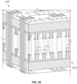
- FIG. 28 is an enlarged view of a portion of the thermal management system shown in FIGS. 27 and 26 , the system including hollow pillars.
- FIG. 29 is a schematic diagram of assembly of an integrated cooling system including an external heat rejection flow loop and a 3D IC packaging with interlayer evaporative cooling platforms.
- FIG. 30 is a sectional view of a portion of the integrated cooling system showing opposed evaporative layers with hollow pillars.
- FIG. 31 is a graph illustrating VOF simulation results for water, showing the evolution of the meniscus and the corresponding capillary pressure at different micropillar locations under three flow rates.
- FIG. 32 is a graph comparing mean curvature and apparent contact angles for droplets, the graph illustrating the geometric evolution of the liquid droplet from a flat liquid meniscus to liquid burst.
- FIG. 33 is a graph of the percentage change in liquid volume within a specified time constant for a liquid droplet with hemispherical geometry under different apparent contact angle numbers.
- FIG. 34 is a graph of the change in total evaporation rate for the triangular and square droplets as a function of time during a transient simulation.
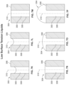
- FIGS. 35 A- 35 D are a series of cross-section profiles of droplets confined on triangular and square micropillars after an equilibrium geometry was obtained.
- FIG. 36 is a graphical plot of the local evaporation flux along a droplet interface along the radial location on the droplet interface for three azimuthal angles for a droplet pinned on a triangular pillar.
- FIG. 37 is a graphical plot of the local evaporation flux along a droplet interface along the radial location on the droplet interface for three azimuthal angles for a droplet pinned on a square pillar.
- FIG. 38 is a graph comparing the local evaporation flux along the liquid-vapor interface of droplets on circular micropillars.
- FIG. 39 is a series of schematic cross-sectional views of pillars with geometric edge features with different edge angles and roundness fabricated using lithography and etching techniques to produce different edge angle and roundness features.
- FIG. 40 is a graph comparing a triple-phase contact line (TPL) to the axis of a micropillar.
- FIG. 41 is a graph of the evaporation rate along the menisci (water) and comparing the triple-phase contact (TPL) line to the axis of the micropillar.
- FIG. 42 is a graph of analytically predicted liquid free energy as liquid flows through a single hollow micropillar.
- FIG. 43 is a graph of analytically predicted liquid pressure variation as liquid flows through a single hollow micropillar.
- FIG. 44 is a flow diagram of an example method of forming a micropillar array.
- FIG. 45 is a schematic illustration of geometric shapes in order of complexity.
- FIG. 46 is an illustration of potential preliminary shapes for a simulation.
- FIG. 47 is an illustration of characteristics of preliminary shapes.
- FIG. 48 is a graphical plot of a Bezier curve.
- FIG. 49 is a graphical plot of curves defining a micropillar shape.
- FIG. 50 is a schematic illustration of a droplet formed on a micropillar.
- FIG. 51 is a flow diagram of an example method of determining a micropillar shape and a droplet shape.
- FIG. 52 is a schematic illustration of a rendering of a droplet shape.
- FIG. 53 is a schematic illustration of a rendering of a complete micropillar and droplet shape.
- FIG. 54 is a graphical plot of results from a simulation and experimental data.
- FIG. 55 is a graphical plot of heat transfer coefficient and illustrating convergence during multiple generations of a simulation.
- FIG. 56 is a graphical plot of heat transfer coefficients for different generations of a simulation.
- FIG. 57 is a top view of a micropillar array with orthogonal spacing between triangular micropillars.
- FIG. 58 is a top view of a micropillar array with uniform spacing between triangular micropillars.
- FIG. 59 is a top view of a micropillar array including micropillars of different heights.
- FIG. 60 is a block diagram of a system for fabricating a micropillar array.
- microstructure and “micro” refer to structures having dimensions less than about 1 millimeter (mm).
- microstructure heat exchangers include heat exchangers in which at least one fluid flows in lateral confinements with an average dimension of less than about 1 mm. While some embodiments herein include microstructures, it is understood that the principles may be applied to larger scale structures without departing from some aspects of the disclosure.
- phase routing evaporative microstructure heat exchanger systems and elements thereof methods of assembling the elements to produce the phase routing evaporative microstructure heat exchanger systems, methods of producing the system elements, 2D and 3D packaged electronics incorporating the phase routing evaporative microstructure heat exchanger systems, and methods of cooling 2D and 3D packaged electronics using the phase routing evaporative microstructure heat exchanger systems are disclosed.
- Embodiments of the microstructure heat exchanger systems include features configured to generate and maintain a plurality of droplets on one or more evaporative surfaces, enabling significantly higher heat exchange coefficients compared to existing heat exchanger systems and devices.
- the disclosed microstructure heat exchanger systems include porous membranes provided with arrays of micropillars configured to generate and maintain single droplets on each micropillar of the array.
- each micropillar is provided with features to further enhance the heat dissipative properties of each micropillar droplet including, but not limited to, at least one additional re-entrant surface feature and nanocoatings.
- At least one of the micropillars has a non-circular shape and produces a non-spherical droplet.
- Evaporation from the non-spherical droplet due to the change in meniscus curvature, exhibits very different interfacial mass transport features from spherical droplets.
- the non-spherical droplet has a higher local vapor concentration gradient that drives faster vapor diffusion at more curved regions.
- the total evaporation rate from a triangular-based droplet is enhanced by 13% compared to a spherical droplet with the same perimeter and liquid-vapor interfacial area.
- triangular-based droplets provide a higher heat transfer coefficient than spherical droplets at a supplied heat flux of 500 W/cm 2 .
- nanocoatings on an evaporative surface may increase wettability and reduce interfacial thermal resistance.
- the nanocoatings may reduce the evaporation rate of liquid on the surface.
- addition of one and three layers of graphene reduces the evaporation rate by 38% and 62% times, respectively, with the same temperature gradient between hot and the cold sources.
- an equilibrated contact angle of argon is increased from 7° to 17° with increasing number of graphene layers.
- Some embodiments provide a hollow micropillar array for an evaporative heat exchanger and methods for optimizing the micropillar array.
- a mathematical model is used to optimize the shape of each hollow micropillar in the array to achieve desired heat transfer performance.
- the model includes defining the geometric shape, determining a droplet shape that is generated by the micropillar shape, completing the micropillar and droplet shapes, performing an evaporative simulation, and performing an algorithm on the shapes to determine the optimal shape.
- the arrangement of the micropillar array is also optimized based on the shape of the micropillars.
- FIG. 1 is a schematic illustration of a portion of an electronic device 100 and a thermal management system 102 .
- the thermal management system 102 includes a heat exchanger 104 including a liquid delivery layer 108 and an evaporation layer 110 .
- the heat exchanger 104 is thermally coupled to at least one electronic component 106 of the electronic device 100 and is configured to remove heat from the electronic component 106 via a heat transfer medium.
- the liquid delivery layer 108 is thermally coupled to the electronic device 100 such that the heat transfer medium receives heat from the electronic component 106 .
- the heat transfer medium may be a phase changing fluid and the heat exchanger 104 may operate as a two-phase cooling system.
- the heat exchanger 104 may utilize a different cooling method such as single-phase cooling and/or air cooling without departing from some aspects of this disclosure.
- the evaporation layer 110 includes a first surface 112 coupled to the liquid delivery layer 108 , a second surface 114 opposite the first surface 112 , and a plurality of hollow pillars 116 extending from the second surface.
- Each hollow pillar 116 includes a stem 118 , an evaporation surface 120 , and a pore 122 .
- Each stem 118 has a proximal end 124 joined to the second surface 114 and a distal end 126 opposite the proximal end 124 .
- Each pore 122 extends through the stem 118 from the proximal end 124 to the distal end 126 and is configured to channel liquid received from the liquid delivery layer 108 through the stem 118 to the evaporation surface 120 .
- Each evaporation surface 120 is on the distal end 126 of the stem 118 of one of the hollow pillars 116 .
- the evaporation surfaces 120 may be annular surfaces on a rim of the stems 118 .
- the evaporation surfaces 120 may be defined solely by the thickness of the wall 128 .
- at least one evaporation surface 120 may be defined by a flange or cap extending around the wall 128 and/or extending radially inward from the wall 128 . Such a flange or cap may at least partially form a head of the hollow pillar 116 .
- the hollow pillars 116 are configured to receive the continuous flow of the liquid from the liquid delivery layer 108 and evaporate the continuous flow of liquid from droplets maintained on the evaporation surfaces 120 .
- Each evaporation surface 120 has a wetting efficiency and is configured to maintain a droplet on the respective hollow pillar within a contact line where the meniscus meets the evaporation surface 120 .
- the contact line may have a length of less than about 0.0314 mm.
- the wetting efficiency is at least about 95%.
- a non-circular evaporation surface 120 has a perimeter-to-area ratio that is at least 10% greater than the area of a circular surface, as a percentage of the circular area.
- At least one of the hollow pillars 116 may have a non-circular cross-sectional shape.
- the hollow pillars 116 may have a cross-sectional shape that is square, rectangular, triangular, star-shaped, polygonal, star-shaped polygon, airfoil shaped, streamline shaped, and any other suitable non-axisymmetric shapes.
- the hollow pillars 116 may be non-axisymmetric and may provide non-spherical droplets.
- the shape of the hollow pillars 116 controls the pinning of the droplets and may be designed to control the evaporation and/or heat transfer of the droplets.
- a droplet with a square or a triangle cross-sectional shape yields a larger contact line length and therefore a greater portion of thin film region, due to the larger perimeter-to-solid liquid interfacial area ratio of non-circular shapes such as triangles and squares compared to circles.
- the total evaporating area along the liquid-vapor interface is distributed uniformly across different film thicknesses.
- the fraction of the total evaporating area possessing a smaller film thickness is significantly higher for a non-circular droplet.
- the fraction of the total liquid-vapor interfacial area evaporating with a large liquid thickness is also reduced as the shape of the droplet contact line changes from circle to square and triangle.
- a change in the distribution of the liquid-vapor interfacial area over different film thickness results in a substantial change in the total thermal resistance of the droplet because the conduction resistance inside the droplet is proportional to the liquid film thickness.
- the effective film thickness and conduction resistance of the evaporating droplet are reduced when the shape of the droplet contact line is changed from circle to a square and from a circle to a triangle.
- the local evaporation rate is affected significantly by several factors including the area fraction of the thin film region, the local curvature, the interfacial temperature, and the wall confinement effect.
- Non-spherical droplets exhibit sharper curvatures near both the contact line (i.e., r/R 1 ) and the corner regions (i.e., locations with a higher azimuth angle).
- the percentage of evaporating liquid-vapor area with smaller film thickness e.g., less than 10% of the maximum droplet height
- the average heat transfer coefficients for triangular and square microdroplets with a heat flux of 500 W/cm 2 are 15% and 21% higher than the average heat transfer coefficient for a capped spherical droplet with a heat flux of 500 W/cm 2 .
- the conduction resistance is the dominant resistance during the evaporation process.
- triangular microdroplets have a higher heat transfer performance compared to circular microdroplets at a constant temperature.
- the evaporation flux of microdroplets on a triangular micropillar is 8% larger than the microdroplets on a square micropillar and 45% larger than the microdroplets on a circular micropillar.
- the enhancement in the heat transfer coefficient for the microdroplet evaporating on a triangular micropillar is 46% larger than the microdroplets on a square micropillar and 71% larger than the microdroplets on a circular micropillar.
- each hollow pillar 116 has a height defined between the proximal end 124 and the distal end 126 of the stem 118 .
- the height of the hollow pillar 116 provides a diffusive space below the droplet and an increase in the total evaporation rate of the pillar in comparison to structures with lesser heights or droplets confined on substantially flat surfaces.
- a ratio of the height of at least one hollow pillar 116 to a width of the hollow pillar may be in a range of about 0.1 to about 20 depending on the working conditions of the heat exchanger.
- the height of the hollow pillar 116 is determined based on the temperature condition of the hollow pillar 116 to provide a desired evaporation rate.
- the hollow pillar 116 may reach approximately 98° Celsius during operation and the height of the hollow pillar may be selected to provide a desired evaporation rate at a 98° Celsius operating temperature of the hollow pillar. Moreover, the height may be determined to balance a conduction resistance of the poruous pillar 116 which increases when the height increases and a diffusion transport resistance of the droplet which decreases when the height of the hollow pillar increases.
- an array 2022 includes hollow micropillars 2024 , 2026 having different heights.
- the arrangement of the array 2022 can be determined based on the heights or final shapes of the micropillars 2024 , 2026 .
- final shapes and heights of each micropillar 20224 , 2026 may be entered into a simulation model to determine the arrangement of the array 2022 that will provide the maximum heat transfer coefficient.
- the micropillars 2024 have a greater height than the micropillars 2026 .
- the micropillars 2024 and the micropillars 2026 are arranged in alternating rows.
- the arrangements of the micropillars 2024 , 2026 may provide a greater heat transfer coefficient than other arrangements because the different heights and the arrangement of the micropillars allow for a spacing between the heads of the micropillars that enables efficient droplet pinning and evaporation and maximizes the number of the micropillars that are on the surface.
- the arrangement of the micropillars 2024 , 2026 may be selected by simulations in which conditions such as the height of the micropillars, the spacing of the micropillars, and/or the rows or alignment of the micropillars is varied.
- the thermal management system 102 includes microstructures and the heat exchanger 104 is configured to function as a microheat exchanger.
- the height of each hollow pillar 116 may be less than about 1 millimeter.
- the height of at least one hollow pillar 116 is in a range of about 1 nanometer to about 100 micrometers.
- the liquid provided by the liquid delivery layer 108 is dialectic. Accordingly, the heat exchanger 104 may be used with sensitive electronic components 106 without risk of the liquid damaging the components. As described further herein, the configuration of the hollow pillars 116 enables the use of low surface tensions fluids such as dialectic liquids because the hollow pillars are able to maintain and evaporate droplets of dialectic liquids.
- the heat transfer medium is used to remove heat from the electronic components 106 . At least some of this heat is dissipated as the droplets evaporate. In addition, at least some of this heat is transferred through the evaporation layer 110 as the liquid is provided by the liquid delivery layer 108 . Accordingly, the hollow pillars may be heated to temperatures greater than ambient temperature. The higher temperature provides a higher evaporation rate and higher heat transfer performance than materials at ambient temperature. The temperature is controlled to be less than the saturation temperature to prevent boiling of the liquid. For example, in some embodiments, at least one of the hollow pillars 116 is heated to a temperature close to the saturation temperature of the working liquid (98° Celsius for water at atmosphere).
- the liquid evaporates continuously from droplets that pin on the tops of the hollow pillars 116 .
- additional liquid is continuously supplied through the pores 122 of the hollow pillars 116 into the pinned droplets.
- the continuous supply of liquid is controlled to maintain the shape of the interface of the droplet and maintain the inlet pressure of the liquid at the pore 122 .
- the equilibrium geometry associated with minimum total surface energy is no longer a capped sphere, but instead assumes an irregular or non-axisymmetric shape where the total and local curvature vary significantly along the liquid-vapor interface.
- the local curvature of the droplet's liquid-vapor interface influences the droplet's capillary pressure, vapor pressure along the meniscus, and the internal circulation inside the droplet, and by extension the droplet's evaporation characteristics.
- the non-circular evaporation surface 120 provides a droplet with a higher evaporation rate per unit area than circular surfaces because (1) the ratio of contact line length of the droplet to droplet surface area is greater for droplets on the non-circular surfaces than for droplets on circular surfaces, and (2) non-axisymmetric droplets provided the non-circular evaporation surface 120 have larger effective thin film regions compared to circular droplets.
- the operating parameters of the system 102 are controlled to maintain stable droplets on the hollow pillars 116 as a continuous flow of liquid is provided to the evaporation layer 110 .
- the dynamic flow conditions of the liquid provided by the liquid delivery system are controlled to provide a desired maximum retention pressure based at least in part on the geometry of the hollow pillars 116 .
- the shapes of the hollow pillars 116 allow the system 102 to maintain stable droplets on the hollow pillars using both high surface tension liquids and low surface tension liquids because the liquids are pinned on the edges of the hollow pillars.
- the stable droplets maintained on the hollow pillars 116 are characterized by a convex meniscus shape with liquid-vapor interfacial area that provides relatively high heat transfer coefficients as compared to existing materials.
- sharp geometric features may restrict contact line advancement of low surface tension liquids (e.g., oils) due to the change in interfacial energy along the solid-liquid interface.
- low surface tension liquids e.g., oils
- the contact line stays pinned until external forces overcome the wetting energy barrier.
- the fundamental mechanisms that hinder low surface tension liquids in wetting over a solid edge are typically characterized by pinning/de-pinning criteria that are influenced by one or more geometrical features of the solid edge including, but not limited to, edge angle and edge roundness.
- the hollow pillars 116 are shaped and constructed to enhance the area fraction of the thin film evaporation region (transition and intrinsic) and to increase the average heat transfer coefficient.
- the thermal management system 102 is configured to transfer heat generated by electronic components 106 packaged in a 2D arrangement.
- the thermal management system includes the liquid delivery layer 108 coupled to a 2D device layer and further coupled to a manifold layer 132 .
- the electronic components 106 are coupled to a metallic conducting and bonding layer 134 bonded to a thermally conductive substrate 136 including, but not limited to, a Si substrate with a thin SiO 2 layer.
- the thermally conductive substrate 136 is further coupled to the liquid delivery layer 108 . As illustrated in FIG. 3 , the thermally conductive substrate 136 is coupled to an exposed face of the liquid delivery layer opposite to the face coupled to the evaporation layer.
- the manifold layer 132 is coupled to the liquid delivery layer 108 at a liquid inlet 138 configured to conduct a liquid coolant from a coolant source to the liquid delivery layer.
- the manifold layer 132 is further coupled to the evaporation layer 110 at a vapor outlet 140 configured to conduct vapor evaporated from the coolant droplets retained on the array of hollow micropillars away from the liquid delivery layer.
- the liquid is delivered to the liquid delivery layer 108 via the liquid inlet 138 .
- the liquid is conducted through the manifold layer 132 via bulk flow, and passes through the liquid delivery layer 108 .
- the array of hollow pillars 116 receive liquid from the liquid delivery layer 108 and form droplets.
- the liquid is vaporized from the surface of the droplets and is continuously replenished by the liquid delivery layer 108 .
- the vaporized fluid released from the evaporation layer 110 passes out of the heat exchanger via the vapor outlet 140 of the manifold layer 132 .
- a method of evaporating a liquid using the thermal management system 102 includes providing a flow of liquid to the evaporation layer 110 .
- the liquid flows through the pores 122 of the hollow pillars 116 and wicks out of the pores 122 along the evaporation surfaces 120 .
- the pore 122 is positioned in the center of the evaporation surface 120 and the liquid wicks radially outward from the pore to an edge circumscribing the evaporation surface.
- the liquid is pinned at the edge and forms a droplet with a contact line extending along the edge and circumscribing the evaporation surface 120 .
- the method also includes maintaining a droplet on each of the hollow pillars 116 and evaporating the flow of the liquid from a surface of the droplet which is maintained on each pillar.
- FIG. 4 is an example embodiment of an array of hollow pillars 200 for evaporating droplets.
- FIG. 5 is a schematic cutaway view of one of the hollow pillars 200 .
- FIG. 6 is a cross-sectional view of the hollow pillar 200 shown in FIG. 5 .
- each hollow pillar 200 includes a stem 202 and a head 204 attached to a distal end of the stem.
- the stem 202 includes a wall 222 defining a pore 206 that channels liquid through the hollow pillar 200 .
- the wall 222 has thickness 224 defined between an inner surface defining the pore 206 and an outer surface spaced radially outward from the inner surface.
- the head 204 has an evaporation surface 208 that is in flow communication with the pore 206 .
- the pore 206 is positioned in the center of the evaporation surface 208 such that the liquid wicks radially outward from the pore and forms a droplet on the evaporation surface 208 .
- the evaporation surface 208 is configured to maintain the droplet on the hollow pillar within a contact line.
- the wetting efficiency is at least 95% and the contact line has a length less than about 0.0134 mm.
- the head 204 includes a flange 210 extending around and radially outward from the stem 202 .
- the flange 210 at least partially forms the evaporation surface 208 .
- the flange 210 includes an edge 212 that circumscribes and extends downward from the evaporation surface 208 .
- the flange 210 also includes a bottom edge 214 and an inner edge 216 .
- the bottom edge 214 extends radially inward from the outer edge 212 and to the inner edge 216 .
- the inner edge 216 extends upward from the bottom edge 214 .
- An overhang surface 218 extends from the inner edge 216 to the stem 202 .
- the flange 210 extends the area of the evaporation surface 208 and provides further control of the evaporation of the liquid from the droplet. For example, at least a portion of the fluid-vapor interface of the liquid provided to the evaporation surface 208 is pinned at a contact line defined by the outer edge 212 under certain flow conditions.
- the edges 212 , 214 , 216 are relatively sharp edges (e.g., the edges define an angle of at least about 85°). Accordingly, the edges 212 , 214 , 216 may act as reentrants to pin at least a portion of the fluid-vapor interface at a contact line defined by the edges under certain flow conditions.
- the term reentrant refers to an abrupt turn in a direction of a surface wetted by a fluid.
- the evaporation surface 208 may further include a nanocoating 230 on at least a portion of the evaporation surface 208 that is wetted by the liquid.
- the nanocoating 230 may be on a portion of the evaporation surface 208 defined by the flange 210 and a portion of the evaporation surface 208 defined by a rim of the stem 202 .
- the nanocoating includes a plurality of nanostructures attached to the flange and/or rim surface.
- suitable nanostructures include nanoparticles such as nanotubes, nanowires, nanospheres, nanoshells, and any other suitable nanoparticle.
- the nanocoatings may be formed from any suitable material including, but not limited to, carbon and gold.
- the nanocoatings are configured to functionalize the wetted surfaces of the micropillar to enhance liquid pinning and evaporation.
- the functionalized flange and/or rim surfaces are configured to enhance droplet formation and retention by the hollow pillars 200 .
- the nanocoatings 230 on the evaporation surface 208 can yield reduced interfacial thermal resistance and higher effective contact area at a solid liquid interface which enhances liquid pinning and evaporation.
- the nanocoatings 230 may be constructed from materials, including but not limited to gold nanotubes, gold nanowires, graphene oxide (GO) layers, and reduced graphene oxide (RGO) layers, by surface engineering with 2D nanomaterials to enable high specific surface area.
- the nanocoatings 230 can be designed to increase two-phase heat transfer flux in comparison to the heat transfer flux from surfaces without nanocoatings.
- FIGS. 7 A- 7 P are a series of schematic diagrams illustrating various stages of fluid transport through an inner channel 300 of a hollow pillar 302 .
- the hollow pillar 302 includes an evaporation surface 304 , an outer edge 306 circumscribing the evaporation surface, and an inner edge 308 at least partially defining the inner channel 300 extending along a longitudinal axis 310 of the micropillar.
- the hollow pillar 302 has a circular cross-section.
- the hollow pillar 302 may be any shape including, for example, and without limitation, square and triangular (e.g., triangles and pseudotriangles).
- the hollow pillar 302 is a microstructure and the width of the inner channel 300 is less than about 1 micrometer.
- a liquid advances through the inner channel 300 of the hollow pillar 302 by means of by capillary action, defined herein as fluid flow within narrow spaces impelled by intermolecular adhesive forces between the liquid and surrounding surfaces and/or surface tension of the liquid.
- FIGS. 7 A- 7 P illustrate the action of the liquid advancing through and being retained by the hollow pillar 302 and shows the contact line dynamics for a wetting liquid as it advances toward the external orifice in one aspect.
- the behavior of liquids advancing through pillars differs significantly depending at least in part on the composition of the liquid.
- liquids characterized as high surface tension (i.e. polar) liquids and low surface tension (i.e. non-polar) liquids behave differently within micropillars, as illustrated in FIG. 7 .
- Non-limiting examples of high surface tension liquids include polar liquids such as water.
- Non-limiting examples of low surface tension liquids include non-polar liquids such as dielectric fluids.
- the hollow pillar 302 is configured to retain liquids characterized by relatively small equilibrium contact angles. In addition, the hollow pillar 302 is configured to enhance liquid retention and to inhibit bursting behavior. Accordingly, the hollow pillar 302 may be used with low surface tension fluorinated compounds including, but not limited to, dielectric liquids. In addition, the hollow pillar 302 may be used to enhance the performance of phase management-related applications requiring stable liquid-vapor interfaces, including, but not limited to, thermal management applications. In some embodiments, the hollow pillar 302 facilitates the routing and phase management of dielectric working fluids for application in heat exchangers. By way of non-limiting example, the hollow pillar 302 may be combined with a composite heat sink to produce an integrated two-phase thermal management system.
- the liquid After the liquid advances onto the evaporation surface 304 , the liquid is pinned by the edge of the hollow pillar 302 and forms a droplet on the hollow pillar 302 .
- the ability of the edges to pin the spreading liquid is determined based on the apparent angle of the liquid relative to the evaporation surface 304 . Specifically, the contact line of the liquid will stay fixed at the edge as long as the apparent contact angle does not exceed a critical value ⁇ *.
- the contact angles measured for liquid advancing and receding on a substrate are different from the static contact angle, as shown by the following relationship: ⁇ adv > ⁇ y > ⁇ rec Eqn. (2) where ⁇ adv is the advancing contact angle and ⁇ rec is the receding contact angle.
- CAH contact angle hysteresis
- surfaces with high roughness generally exhibit high CAH, and it becomes more difficult to remove a pre-wetted liquid from such surfaces (e.g., water-oil displacement).
- hysteresis may be induced by microscopic defects whose geometric discontinuities resist liquid spreading.
- the high surface tension liquid pins along the inner edge 308 , as illustrated in FIG. 7 B , until a convex meniscus is formed along the inner channel 300 , as illustrated in FIG. 7 D .
- the convex meniscus enlarges and advances along the evaporation surface 304 , as illustrated in FIG. 7 E , until the meniscus is pinned along the outer pillar edge 306 as shown in FIG. 7 F .
- the pinned meniscus expands and that yields a minimum radius of curvature and a maximum Laplace pressure, as illustrated in FIG. 7 G .
- the pinned meniscus forms a hemispherical shape if the evaporation surface is circular and non-axisymmetric shape if the evaporation surface is non-circular.
- the growing meniscus forms a pressure barrier attributed to changes in meniscus interfacial area.
- a resistive capillary force opposes any further increases in surface area and associated increases in total interfacial energy, and consequently prevents the meniscus from further expansion beyond the outer edge 306 of the hollow pillar 302 .
- a convex meniscus implies a positive pressure of the wetting liquid with respect to the non-wetting phase (i.e., p w >p nw ).
- the liquid For low surface tension (e.g., non-polar) liquids, the liquid initially wicks through the inner channel 300 of the hollow pillar 302 , as illustrated in FIG. 7 K . The liquid contact line then pins along the inner edge 308 , as illustrated in FIG. 7 L until the liquid levels rise above the inner pillar edge, as illustrated in FIG. 7 M .
- the meniscus immediately advances from the inner edge 308 to the outer pillar edge 306 , as illustrated FIG. 7 N until the liquid is again pinned at the outer pillar edge as illustrated in FIG. 7 O .
- the meniscus expands from the pinned contact line at the outer pillar edge 306 and forms a hemispherical shape on a circular evaporation surface 304 and a non-axisymmetric shape on a non-circular evaporation surface.
- the meniscus expands until the apparent contact angle, ⁇ a between the evaporation surface 304 and the meniscus liquid-vapor interface reaches the critical angle ⁇ *.
- the critical angle ⁇ * may be 90° for the low surface tension liquids, as illustrated in FIG. 7 P .
- a nanocoating is applied to the surface to provide a superoleophilic surface (e.g., a surface including an oil with a contact angle less than 10°) which will shift the wetting characteristic of the surface from state 3 to state 1 or provide a superoleophobic surface (e.g., a surface including an oil with a contact angle greater than about 150°) which will shift the wetting characteristic of the surface from state 3 to state 3.
- a superoleophilic surface e.g., a surface including an oil with a contact angle less than 10°
- a superoleophobic surface e.g., a surface including an oil with a contact angle greater than about 150°
- FIG. 8 is a perspective view of a hollow pillar 400 .
- FIG. 9 is a schematic cross-sectional view of the hollow pillar 400 illustrating liquid advancing through the hollow pillar.
- the wicking, pinning, and bursting behavior of liquid along the hollow pillar 400 can be analyzed theoretically using a free energy approach with a quasi-static assumption.
- FIGS. 10 A- 10 D are a series of schematic diagrams illustrating various stages of fluid movement through an inner channel 500 of a micropillar 502 .
- the stages for the meniscus formed on the micropillar 502 include a wicking stage 504 , a pivoting stage 506 , an advancing stage 508 , and an expanding stage 510 .
- both high surface tension and low surface tension liquids advance through the narrow inner channel 500 formed within the micropillar 502 during the wicking stage 504 .
- the liquids may initially have a concave surface profile and then form the meniscus during the pivoting stage 506 as the meniscus transitions from the concave surface profile to a convex surface profile.
- the liquid travels across a surface of the micropillar 502 and undergoes pinning of the meniscus to the sharp outer edge of the micropillar at the end of the meniscus advancing stage 508 .
- the pinned meniscus continues to grow during the expanding stage 510 .
- the physical phenomena related to meniscus pinning referred to herein as the canthotaxis effect, provide a thermodynamic framework for describing the resistance of wetting liquids spreading along sharp edges.
- ⁇ x apparent contact angle
- ⁇ * critical angle
- E tot E 0 - ⁇ ⁇ dh ⁇ ⁇ l ⁇ a ⁇ cos ⁇ ⁇ y .
- V tot V 0 + ⁇ 4 ⁇ d 2 ⁇ h .
- E tot E 1 - ⁇ ⁇ d 2 2 ⁇ ( 1 - sin ⁇ ⁇ y cos 2 ⁇ ⁇ y - 1 - sin ⁇ ⁇ x cos 2 ⁇ ⁇ x ) ⁇ ⁇ la .
- V tot V 1 + ⁇ ⁇ d 3 24 [ ( 1 - sin ⁇ ⁇ y ) 2 ⁇ ( 2 + sin ⁇ ⁇ y ) cos 3 ⁇ ⁇ y - ( 1 - sin ⁇ ⁇ x ) 2 ⁇ ( 2 + sin ⁇ ⁇ x ) cos 2 ⁇ ⁇ x .
- E tot E 2 + ⁇ ⁇ ( l 2 + dl ) ⁇ ( 2 - 2 ⁇ cos ⁇ ⁇ y sin 2 ⁇ ⁇ y - cos ⁇ ⁇ y ) ⁇ ⁇ la .
- V tot V 2 + ⁇ ⁇ ( 1 - cos ⁇ ⁇ y ) 2 ⁇ ( 2 + cos ⁇ ⁇ y ) 24 ⁇ sin 3 ⁇ ⁇ y [ ( d + 2 ⁇ l ) 3 - d 3 ] .
- E tot E 3 + ⁇ ⁇ D 2 2 ⁇ ( 1 - cos ⁇ ⁇ x sin 2 ⁇ ⁇ x - 1 - cos ⁇ ⁇ y sin 2 ⁇ ⁇ y ) ⁇ ⁇ la .
- V tot V 3 + ⁇ ⁇ D 3 24 [ ( 1 - cos x ) 2 ⁇ ( 2 + cos ⁇ ⁇ x ) sin 3 ⁇ ⁇ x - ( 1 - cos ⁇ ⁇ y ) 2 ⁇ ( 2 + cos ⁇ ⁇ y ) sin 3 ⁇ ⁇ y ] .
- the contact line splits into a capped sphere sitting on the top of the micropillar and a falling film surrounding the outer micropillar wall.
- the free energy during burst is irregular due to the irregular shape deformation of the liquid spreading down the micropillar.
- no additional pressure barrier remains, and subsequent flow is again dominated by the contact line friction as the liquid spreads freely over the entire substrate.
- the corresponding liquid pressure variation after the burst can then be calculated, again using the change in free energy, as described in Eqns. (12) and (13).
- the stability at which a liquid is pinned to an enclosing edge of the micropillar varies in proportion to the intrinsic contact angle, corresponding to the solid-liquid interfacial energy.
- the micropillar's non-axisymmetric shape may yield a higher evaporation rate. Exploring the evaporation flux distribution in a drop with circular and triangular contact area demonstrated that larger curvature provided by the triangular contact area leads to larger evaporation flux and that larger mean curvature leads to larger total evaporation as shown in FIGS. 11 and 12 . Specifically, FIG. 11 shows the curvature and vapor concentration line of a droplet on a circular evaporation surface. FIG.
- FIGS. 11 and 12 show the curvature and vapor concentration line of a droplet on a triangular evaporation surface.
- FIGS. 11 and 12 show an increased evaporation flux for the triangular evaporation surface with the larger mean curvature.
- a triangular droplet evaporates 17% faster than a hemispherical droplet with same liquid-vapor interfacial area and same base perimeter at room temperature and atmosphere.
- the enhancement in the heat transfer coefficient for the microdroplet evaporating on a triangular micropillar is 46% larger than the microdroplets on a square micropillar and 71% larger than the microdroplets on a circular micropillar.
- thermodynamic analysis provides a sound explanation of most liquid retention behaviors at sharp edges, subject to at least several assumptions.
- the thermodynamic analysis described herein is based on a quasi-static assumption that the process is reversible. In other words, the system is always at its local energy minimum state and the change in total free energy is contributed to only by the change in total surface energy, as expressed by:
- ⁇ is the chemical potential and a is the surface tension.
- the quasi-static assumption may not be appropriate for highly non-equilibrium conditions (e.g., a high flow rate) where the liquid meniscus shape deformation by external perturbation cannot be instantaneously restored by surface tension force, resulting in systems characterized by transient states and non-constant system pressures.
- a high flow rate fluid displacement in porous media
- an interfacial meniscus may progress abruptly through a geometric throat, unbounded by the quasi-static thermodynamic descriptions. In this case, the progression contact angle ⁇ exceeds the intrinsic contact angle ⁇ y .
- onset of non-equilibrium behavior of droplets during transient states may be identified using Capillary number, defined as:
- ⁇ is the viscosity
- v is the velocity
- ⁇ is the surface tension
- the liquid flow can be generally analyzed using free-energy methods with the quasi-static assumption as described above.
- a liquid droplet pinned on a cylindrical tube typically undergoes an anisotropic expansion with a higher growth rate in the vertical direction. Therefore, the droplet expands beyond the maximum shape predicted by the quasi-static thermodynamic analysis before spilling occurs.
- the high flow rate reduces the wetting barrier at the sharp solid edge.
- the behavior of the liquid contact line of droplet expansion and advancing along a sharp edge may be evaluated in terms of interfacial molecular interactions in addition to the thermodynamic free energy methods described above.
- interfacial interactions By studying the interfacial interactions in the vicinity of the contact line region and developing a general description for liquid spreading on arbitrary curved surfaces, contact line dynamics and flow behavior over a variety of geometries, such as porous media and textured substrates that contain “macroscopic” sharp features may be predicted.
- wetting behavior of droplets on solid substrates are not governed by phenomena occurring over the entire wetted area, but instead are governed by interfacial interactions within a very small region positioned beneath the liquid juxtaposed with the contact line.
- This one-dimensional (1D) contact line when magnified at the nanoscale, becomes a 3D space ( ⁇ 10 nm) where the molecules of the liquid, solid, and gas phases interact. These interactions drive the contact line and bulk liquid to advance along the solid surface.
- the same principle should hold as long as the apparent contact angle ⁇ a is less than the critical contact angle ⁇ * defined above in Eqn. (1).
- the contact line may spontaneously spill along the solid substrate when ⁇ a exceeds ⁇ *, despite the fact that its local contact angle is less than its local equilibrium state (i.e., ⁇ local ⁇ y ).
- Non-uniform evaporation from the contact line of the droplet are thought to induce microconvection effects in both the liquid and vapor domain that accelerate the evaporation process. It has also been demonstrated that a temperature gradient along the droplet surface, induced by the self-cooling of the droplet surface during evaporation, may subsequently induce thermocapillary flow inside a droplet.
- FIGS. 13 - 15 are top views of hollow pillars 600 , 602 , 604 having different cross-sectional shapes.
- hollow pillar 600 has a circular cross-sectional shape.
- Hollow pillar 602 has a square cross-sectional shape.
- Hollow pillar 604 has a triangular cross-sectional shape.
- Each hollow pillar 600 , 602 , 604 has an inner edge 608 defining a pore 606 and an outer edge 610 spaced radially outward from the inner edge.
- Micro/nano structures are able to tune and control droplet geometries including, but not limited to, non-axisymmetric droplet contact area shapes such as squares, rectangles, hexagons, octagons, dodecagons, star shaped polygon, airfoil shape, and streamlined shape using advanced micro- and nano-fabrication techniques.
- the non-axisymmetric contact areas typically result in non-spherical droplet geometries for which the liquid-vapor interface is not amenable to characterization using existing explicit function such as the expressions described above.
- the curvature of the liquid-vapor interface is non-uniform over the droplet surface, which leads to drastic changes of the local vapor concentration gradient in the azimuthal direction, as illustrated in FIGS. 13 - 15 .
- non-axisymmetric droplets Compared to spherical droplets where the local evaporative flux distribution is solely determined by the contact angle, non-axisymmetric droplets exhibit different evaporative transport characteristics, since both the shape and proximity to the triple phase contact line (TPL), defined as the region where the solid, liquid, and vapor molecules interact, influences the droplet's evaporation flux.
- TPL triple phase contact line
- droplets with a higher mean interface curvature evaporate at a faster rate, which is a desirable characteristic for an efficient evaporative cooling system.
- FIGS. 16 and 17 are schematic diagrams of an example fabrication process of hollow micropillars.
- the first method is for a re-entrant profile (see FIG. 16 ) and the second method is for a double re-entrant profile (see FIG. 17 ).
- the double re-entrant profile is a three-stage microfabrication procedure for manufacturing the hollow micropillar with desired geometry.
- microfabrication techniques were applied to create a membrane containing an array of hollow micropillars with re-entrant surface features from a material such as silicon.
- the hollow micropillars are constructed using two front-side deep reactive ion-etching (DRIE) steps to independently delineate trenches and through-holes.
- DRIE deep reactive ion-etching
- an additional back-side DRIE step may be conducted to define the membrane thickness.
- the inner diameter of the micropillars may be limited by the resolution of the lithography and/or the DRIE steps, both of which may are typically well-suited for the formation of high aspect ratio through-holes.
- the micropillar inner diameter is about 3 ⁇ m
- the membrane thickness is about 0.7 ⁇ m
- the corresponding micropillar outer diameter is about 4.4 ⁇ m.
- the area of the micropillar arrays fabricated here was about 1 mm 2 .
- the DRIE etch produced sharp edges at the intersection of the outer and top surfaces of the micropillars (i.e., angle ⁇ 90° as defined in FIG. 7 J ), suitable for pinning liquids with infinitesimal intrinsic contact angles including, but not limited to dielectric fluids characterized by low surface tension as described above.
- the outer corner of each micropillar has an etch angle less than about 90° which enables lower surface tension liquids to maintain a meniscus with a hemispherical shape when the liquid is pinned along the outer pillar edge as described above.
- multiple integrated liquid delivery layers may be combined in various arrangements to provide thermal management to a variety of arrangements of power electrical components.
- a pair of integrated liquid delivery and evaporation layers 700 are coupled to opposite faces of a 2D device layer 702 .
- the first integrated liquid delivery and evaporation layer 700 is coupled to the first/upper face of the device layer 702 at a thermally conductive substrate via a metallic conductive layer as described above.
- the second integrated liquid delivery and evaporation layer 700 is similarly coupled to a second/lower face of the device layer 702 opposite the first/upper face.
- the integrated liquid delivery and evaporation layers 700 include liquid delivery layers 704 connected to the device layers 702 and evaporation layers 706 connected to the device layers 702 opposite the device layers 702 .
- the liquid delivery layers 704 may include a structure such as matrix foil or a series of pillars that allows wicking of the liquid therethrough and facilitates transfer of heat from the device layers 702 to the evaporation layers 706 .
- the liquid inlet of the manifold (not shown) is coupled to the liquid delivery layers 704 of both integrated liquid delivery and evaporation layers 700 and the vapor outlet of the manifold (not shown) is coupled to the evaporation layers 706 of both integrated liquid delivery layers.
- single integrated liquid delivery layers and device layers are interspersed in alternating layers, as illustrated in FIGS. 18 - 21 .
- a double sided cooling module for a MOSFET 900 and a double sided cooling module for a diode 901 are layered between two copper buses 902 .
- a pair of integrated liquid delivery layers are coupled together in an adjacent arrangement to form an assembly 1000 as illustrated in FIG. 22 - 24 .
- a first/upper integrated liquid delivery layer 1001 is coupled to a second/lower integrated liquid delivery layer 1002 such that a gap is maintained between a first evaporation layer of the first/upper integrated liquid delivery layer and a second evaporation layer of the second/upper integrated liquid delivery layer.
- the first and second evaporation layer are coupled via the through-silicon vias (TSVs) of a 3D electronic device package.
- TSVs through-silicon vias
- the manifold is coupled to each evaporation layer and liquid delivery layer via the vapor outlet 1003 and liquid inlet 1004 , respectively.
- the vapor produced by the evaporation layers of the coupled integrated liquid delivery layers is released into the gap between the evaporation layers, and passes into the vapor outlet of the manifold.
- the pair of integrated liquid delivery layers are coupled to a functional power device layer 1005 , part of the 3D electronic delivery package.
- the functional power device layer 1005 is made up of a metal layer 1006 , a silicon layer 1007 , and a power semiconductor 1008 .
- multiple coupled pairs of integrated liquid delivery layers as described above are interspersed in alternating layers with device layers, as illustrated in FIG. 25 - 30 .
- Each coupled pair of integrated liquid delivery layers are coupled to the liquid inlet and vapor outlet of a manifold.
- a thermal management system 1100 further includes a cooling fluid reconditioning loop coupled to the manifold 1105 .
- the cooling fluid reconditioning loop is configured to receive vapor from the vapor outlets 1101 of the manifold and to deliver chilled cooling liquid back to the liquid inlets 1102 of the manifold 1105 .
- the cooling fluid reconditioning loop includes a condenser 1103 coupled to the vapor outlet of the manifold. The condenser is configured to receive and convert vaporized cooling fluid to cooling liquid.
- the cooling fluid reconditioning loop further includes a radiator 1109 coupled to the condenser and configured to release heat from the cooling fluid.
- the cooling fluid reconditioning loop further includes a pump 1104 configured to move the reconditioned cooling fluid into the fluid inlet of the manifold.
- the manifold 1105 directs the cooling fluid into separate channels 1106 connected to integrated liquid delivery and evaporation layers 1107 .
- the layers 1107 are configured to manage heat of multiple stacked electronic devices.
- the manifold 1105 substantially encloses the stacked electronic devices and the integrated liquid delivery and evaporation layers 1107 .
- the manifold 1105 is sized and shaped to allow the electronic devices and the integrated liquid delivery and evaporation layers 1107 to have a compact configuration and be modular.
- the liquid inlets 1102 and the vapor outlets 1101 include channels extending along sides of the assembly.
- the integrated liquid delivery and evaporation layers 1107 each include a liquid delivery layer 1110 configured to thermally couple to electronic components and an evaporation layer 1112 attached to the liquid delivery layer 1110 opposite the electronic components.
- a Volume of Fluid (VOF) numerical model is used to characterize the evaporation behavior of non-axisymmetrical microdroplets suspended on a hollow micropillar.
- the VOF model is used to characterize the heat and mass transfer over a non-axisymmetric microdroplet meniscus formed at the outlet of a hollow micropillar.
- equilibrium profiles and mass transport characteristics of droplets with circular, triangular, and square contact shapes are characterized using the Volume of Fluid (VOF) method.
- the VOF model is based on a volume of fluid (VOF) multiphase method that accounts for microconvection effects within the droplet and evaporative phase change transport at the liquid-vapor interface, and further provides representation of the vapor diffusion process in the air domain.
- evaporative mass transport at the liquid-vapor interface is modeled using a simplified Schrage model.
- the VOF numerical model predicts highly non-uniform mass transport characteristics for non-axisymmetrical microdroplets, where a higher local evaporation rate is observed near the locations where the meniscus has high curvature. This observation is attributed to a higher local vapor concentration gradient that drives faster vapor diffusion at more curved regions, analogous to a lightning rod exhibiting a strong electric field along a highly curved surface.
- this contact line confinement phenomenon may be used to artificially tune a droplet into a more curved geometry, resulting in enhanced total evaporation rate of as much as 13% from a triangular-based droplet compared to a spherical droplet with the same perimeter and liquid-vapor interfacial area.
- manipulation of contact line confinement may influence the design and optimization of geometric features to improve evaporation in high performance electronics cooling systems.
- a transient three-dimensional simulation model using the Volume of Fluid method is developed to predict the liquid pressure and capture the contact line dynamics as the meniscus advances from the inner channel to the outer edge of the hollow micropillar.
- the simulation tracks the evolution of the meniscus and corresponding pressure profile as the meniscus moves to different locations along the micropillar.
- the VOF model employs one set of governing equations to solve for the liquid and vapor domains, using ANSYS Fluent.
- the computational solver is implemented to compute the conservation equations below:
- ⁇ k , ⁇ , ⁇ , and ⁇ right arrow over (F) ⁇ are the phase volume fraction, density, dynamic viscosity, and body force terms, respectively.
- ⁇ and ⁇ are the surface tension and surface curvature, respectively.
- a three-dimensional computational domain is used for the simulation.
- a micropillar is considered, with an inner diameter, outer diameter, and thickness of 2.5 ⁇ m, 5 ⁇ m, and 25 ⁇ m, respectively.
- Input parameters Value Outer diameter, D 5 ⁇ m Inner diameter, d 2.5 ⁇ m Micropillar height, h 5 ⁇ m Membrane width, 16 ⁇ m Liquid inlet temperature, T in 293K Liquid inlet Mass Flow rate, m in 2 ⁇ 10 10 kg/s 2 ⁇ 10 ⁇ 9 kg/s 1 ⁇ 10 8 kg/s Ca number 0.001 0.01 0.05 Outlet gauge pressure, P out 0 kPa Properties Water FC-40 Surface tension 7.3 ⁇ 10 2 N/m 1.6 ⁇ 10 ⁇ 2 N/m Viscosity 1.0 ⁇ 10 3 kg/m-s 4.1 ⁇ 10 4 kg/m-s Membrane contact angle 10° 3° Solution methods Setup Number of meshes 0.8 million hexahedral meshes Surface tension modeling Continuous Surface force (CSF) Pressure-Velocity Coupling Pressure Implicit with Spitting of Opesares (PISO) Spatial discretization Gradient Green-Gaus
- FIG. 31 illustrates VOF simulation results for water, showing the evolution of the meniscus and the corresponding capillary pressure at different micropillar locations under three flow rates.
- the pressure response shown in FIG. 31 reveals similar trends in pressure variation, as predicted from quasi-static analytical calculations, in which the wicking, pivoting, advancing, and expansion stages are delineated clearly by changes in pressure.
- the fluctuations in the pressure signal are attributed to perturbation and instability during volume growth. Nevertheless, with increasing flow rate, there is a considerable increase in the liquid pressure due to the intensified viscous pressure. If the viscous pressure drop is subtracted based on Hagen-Poiseuille flow, the critical bursting pressure can be obtained, as shown in Table 2:
- FIG. 32 shows the geometric evolution (i.e., mean curvature and apparent contact angle) of the liquid droplet, starting with a flat liquid meniscus (in the middle of the pivoting stage) and ending with liquid burst.
- a decrease in the mean curvature, x is also observed for high Ca flow, which corresponds to a lower Laplace pressure.
- the liquid expands to a larger critical volume before bursting under the higher flow rate (i.e., high Ca number).
- the inconsistency in the liquid profile and pressure during the process under three flow rates suggests that burst behavior cannot be described solely by quasi-static analysis. This finding suggests that at sufficiently high flow rates, the surface tension force is no longer strong enough to instantly restore the shape of the liquid meniscus to its equilibrium condition. Therefore, the liquid will undergo an anisotropic expansion with a higher growth rate in the vertical direction, during which the surface energy is no longer at its minimized value.
- ⁇ is the surface tension
- ⁇ is the density
- r droplet is the radius of the droplet.
- FIG. 33 illustrates the percentage change in liquid volume within the specified time constant s for a liquid droplet with hemispherical geometry under different Ca numbers.
- the result shows that for Ca number of 0.001, 0.01 and 0.05 respectively, the liquid droplet undergoes 0.2%, 2% and 9% volume changes before its surface can be restored to an equilibrium spherical shape. Therefore, the liquid meniscus will not be able to maintain its minimum energy state during expansion under high Ca number conditions.
- the quasi-static assumption that the droplet will always be at its local equilibrium condition becomes invalid under high Ca numbers, where the change in liquid volume becomes significant.
- VEF Volume of Fluid
- the VOF model included mathematical representations of various aspects of microdroplet formation and evaporation, as described in detail below.
- p v , p l , p c , and p d are defined as the vapor pressure, liquid pressure, capillary pressure, and disjoining pressure, respectively.
- m ′ 2 ⁇ ⁇ 2 - ⁇ ⁇ ( M _ 2 ⁇ ⁇ ⁇ R ) 1 2 ⁇ ( p v eq ( T ls ) T lv 1 / 2 - p v T v 1 / 2 ) Eqn . ( 26 )
- m evap * 2 ⁇ ⁇ 2 - ⁇ ⁇ ( M _ 2 ⁇ ⁇ ⁇ R ⁇ ) 1 2 ⁇ 1 T l ⁇ v 1 2 Eqn . ( 28 ) ⁇ p sat ref ⁇ exp ⁇ ( M ⁇ h fg R _ ⁇ ( 1 ⁇ sat ref - 1 ⁇ lv ) ) ⁇
- m v ′′ M _ ⁇ ( - D ⁇ ⁇ C v ⁇ n + V ⁇ n ⁇ C v ) Eqn . ( 29 )
- m air * M _ ⁇ ( - D ⁇ ⁇ C air ⁇ n + V ⁇ n ⁇ C air ) Eqn . ( 30 )
- Vapor pressure and vapor concentration rate can then be calculated using Eqn. (33) and Eqn. (34) (shown below).
- the interface cells consisted of the liquid phase and air-mix phase, with a phase indicator.
- the evaporation mass flux calculated by the Schrage model was set equal to the vapor diffusion flux derived from the gas domain governing equation. This allowed the calculation of the local evaporation rate along the meniscus after several iterations.
- a user defined function (UDF) was written based on the mathematical model previously discussed and was implemented in ANSYS Fluent R17.1 to perform the simulations.
- the VOF model was implemented subject to several boundary conditions described below.
- the outlet boundary was set as constant atmospheric pressure to simulate the microdroplet's evaporation in ambient environment.
- Adiabatic non-slip walls were assumed along the micropillar top surface.
- the surface was assigned an equilibrium contact angle, ⁇ e , of 23° to enable the droplet to relax its geometry and attain different equilibrium states on different micropillars.
- the simulation domain was initialized with a vapor mass-fraction of 5%.
- the inlet boundary was set as a mass-flow inlet condition with a mass flow rate of 1 ⁇ 10 ⁇ 9 kg/s.
- the inlet boundary condition was changed to a pressure inlet. The pressure value was adjusted carefully, allowing the meniscus to expand and equilibrate so that the total liquid vapor interfacial area was equivalent to a pre-set value.
- the total liquid-vapor interfacial area was kept constant (2 ⁇ 10 ⁇ 11 m 2 ) for evaporation from all three micropillars.
- the total interfacial surface areas for the hemispherical, triangular, and square microdroplets were calculated using Surface Evolver.
- the VOF method was implemented using ANYSTS Fluent R17.1 to simulate two-phase evaporation with a free surface. Each phase was calculated and separated with a volume fraction in mesh cells. This procedure was more flexible and efficient than other methods for treating complicated free boundary configurations.
- a user defined function (UDF) was developed to implement the simplified Schrage model. The source terms in both the mass transfer equation and energy transport equation are created using a user-defined scalar (UDS).
- ICEM 18.0 software was used to generate a structured mesh with a hexahedron shape for the simulation. Because the VOF method was characterized by the mesh of the geometry, the mesh resolution significantly influenced the simulation result. A mesh sensitivity study was conducted to compare three levels of mesh resolution. The base element lengths were 5 nm for fine mesh, 12.5 nm for medium mesh, and 20 nm for coarse mesh. The thickness of the interface (transition region from liquid to vapor) of the coarse mesh was 200% larger than that of the medium mesh, while the difference between the fine mesh and medium mesh was only 10%.
- the interface should be as thin as possible; however, this was not observed for the coarse mesh.
- Table 2 and Table 3 as shown below summarize the total evaporation rates of droplets modeled using the three mesh resolution levels described above, using the Schrage model as described above.
- the equilibrium evaporation rates of the results from coarse mesh were 7.1% larger than those of medium mesh, and the difference between the results from the fine mesh and coarse mesh was only 1%. Therefore, we chose the medium mesh with an element length of 12.5 nm for the simulation.
- the mesh-independence for both the square pillar case and the triangular pillar case were tested, and the results are shown in Table 3 and 4 respectively.
- f( ⁇ ) was a function of the contact angle
- m′′(r) was evaporation flux
- n s density of the saturated vapor
- n ⁇ ambient vapor density
- ⁇ e equilibrium contact angle
- ⁇ droplet interface in toroidal coordinates
- P ⁇ 1/2+i ⁇ was a Legendre function of the first kind
- M was total evaporation rate
- ⁇ was nondimensional time.
- the change in total evaporation rate for the triangular and square droplets as a function of time during the transient simulation are shown in FIG. 34 .
- the vapor fraction in the gas domain was very small and evaporation from the interface was not suppressed by the vapor diffusion.
- initial and total evaporation rates for both cases were around 2 ⁇ 11 kg/s.
- evaporation was hindered by vapor diffusion, resulting in a gradual decrease in the total evaporation rate for both droplets.
- the evaporation rates from the droplet surfaces were the same as the vapor diffusion rates, leading to stable total evaporation rate representing the evaporating behavior of the droplets at the equilibrium state.
- FIGS. 35 A- 35 D show the cross-section profiles of droplets confined on triangular ( FIGS. 35 A and 35 B ) and square ( FIGS. 35 C and 35 D ) micropillars after an equilibrium geometry was obtained.
- the apparent contact angle ⁇ ap varied significantly along the triple phase contact line (TPL).
- the cross-section meniscus exhibited either a hydrophilic (i.e., ⁇ a ⁇ 90°) or a hydrophobic (i.e., ⁇ a >90°) characteristic along the microdroplet.
- a convex meniscus with higher curvature facilitated stronger evaporation and vapor diffusion due to the larger Laplace pressure and higher local concentration gradient. Therefore, higher local curvature also induced stronger evaporation rates at locations with higher azimuthal angles.
- the combined effects of smaller contact angle and higher local curvature at locations with high azimuthal angle contributed to significantly higher local evaporation rates at these locations. Consequently, the triangular and square micropillars exhibited highly non-uniform evaporation over the whole droplet characterized by enhanced local evaporation near edge locations and suppressed local evaporation near the center locations of the microdroplet.
- the micropillars described above exhibited a 90° sharp edge at the contact line region, and therefore did not induce significant vapor diffusion impedance.
- the highest local saturated vapor pressure was always observed at the contact line region.
- This high local vapor pressure induced a vapor concentration gradient near the contact line region and therefore promoted faster vapor diffusion from the contact line to the ambient atmosphere. Consequently, the local evaporation flux along the cross-section profile of a droplet on a micropillar was always the highest near the contact line region in this study regardless of the azimuthal angle.
- whether such characteristic is sustained for droplets with an apparent contact angle exceeding 90° over all azimuthal angles remains to be characterized. Since the contact line region was no longer subjected to wall confinement, it was anticipated that the evaporation rate may still be highest near the contact line even for larger droplets.
- the total evaporation rate of a triangular droplet was 14.3% higher than that of a square droplet, and the total evaporation rate of a square droplet was 5.2% higher than that of a capped spherical droplet. This phenomenon was attributable to the effects of radial curvature and azimuthal curvature associated with micropillar geometry.
- the local evaporation flux along the droplet interface was plotted along the radial location on the droplet interface for three azimuthal angles, as shown in FIG. 36 (for a droplet pinned on a triangular pillar) and FIG. 37 (for a droplet pinned on a square pillar), where the radial location, r, was normalized by the droplet radius, R.
- the local curvature was calculated by the MATLAB curve fitting tool.
- the local evaporation mass flux was compared with the local curvature on a 3D curved interface.
- the local evaporation flux distributions of all three cases followed the same trend where the local evaporation rate increased monotonically from the center of the droplet towards the edge of the droplet. This trend was in accordance with the general evaporation characteristics observed for hydrophilic droplets (i.e., ⁇ e ⁇ 90°).
- the comparison illustrated in FIG. 38 revealed significant deviations between the local evaporation flux curves obtained from the different studies due to the variation in the evaporation conditions (e.g., working fluid, environmental condition, substrate profile).
- the simulation described above assumed evaporation of droplets deposited from vertical micropillars projecting from a substrate as described above, while the previous experimental results were obtained using droplets deposited on planar surfaces.
- evaporation of droplets from planar substrates is thought to prohibit the diffusion of vapor in a downward direction, resulting in reduced total evaporation rate and reduced local evaporative flux near the triple phase contact line (TPL).
- TPL triple phase contact line
- the vapor is thought to diffuse partially in the downward direction at the TPL, yielding both an enhanced local evaporation rate at these regions and a higher total evaporation rate.
- Example 2 Microscale Pinning/De-Pinning of Droplet Contact Lines Advancing Along Sharp Edges with Varying Angle and Roundness
- geometric edge features 905 with different edge angles and roundness were fabricated using lithography and etching techniques to produce different edge angle and roundness features.
- T-shaped microchannels were fabricated on a plain silicon substrate with acute, right, or obtuse turning angles as shown in FIG. 39 .
- the edge radius of curvature at these sharp edges was varied from ⁇ 100 nm, 1 ⁇ m to ⁇ 10 ⁇ m by changing the photolithography mask and controlling the developing/etching process.
- laser scanning lithography was used to produce the target feature on the deposited photoresist material.
- the photoresist was be aligned and patterned with an accuracy of up to 250 nm.
- the substrate surface was functionalized with different chemicals to achieve different surface characteristics (e.g., superhydrophilic and superoleophobic).
- the functional coatings are provided at a uniform thickness by a continuous and smooth deposition of corresponding chemicals at the evaporation interface.
- the geometry of the microchannels and the quality of the nanocoatings were examined under scanning electron microscope (SEM), transmission electron microscope (TEM), atomic force microscope (AFM), and Raman spectroscopes.
- High-speed visualizations of liquid propagating through the microchannel were obtained using both an optical microscope in the ambient environment and an environmental scanning electron microscope (ESEM).
- ESEM environmental scanning electron microscope
- the advantage of an ESEM compared to standard SEMs was that the pressure of the sample vacuum chamber could be separated from the pressure of the beam leading vacuum chamber, therefore providing for sufficiently high working pressure such that water can remain in a liquid state.
- the microchannel was assembled on a liquid feed manifold connected to a micro-injector that provided a continuous inlet flow. Three different flow rates were examined, which corresponded to capillary numbers (Ca) of 0.001, 0.01 and 0.1. Under high Ca, the meniscus exhibited distorted geometry in overcoming the edge structure.
- a pressure transducer was connected to the liquid feed manifold to capture the change in liquid pressure as the meniscus advanced through the edge features.
- a customized testing manifold for capturing the contact line dynamics at nano-length scale as the contact line advances continuously along a highly curved edge with finite length was built.
- a Peltier cooling stage was embedded in the manifold to control the sample temperature below the water dew point at the working pressure. Contact line movement over edge geometry was observable regardless of the magnitude of the radius of curvature. In either case, the local contact angle remained constant along the local geometry.
- Example 3 Microdroplet Evaporation from a Hollow Micropillar
- a multiphase flow numerical simulation for observing microdroplet evaporation from a hollow micropillar was demonstrated.
- Factors in modeling droplets included vapor domain, liquid domain, pressure outlet, vapor diffusion, heat flux wall, axis, and the liquid-solid barrier. Measurements taken included temperature, surface tension, and angular position and observing the triple-phase contact line (TPL) in association to the axis of the micropillar (see FIG. 40 ).
- the evaporation rate along the menisci (water) was demonstrated observing the triple-phase contact (TPL) line in association to the axis of the micropillar as well (see FIG. 41 ).
- the average transfer coefficient versus the boundary heat flux were calculated (see FIG. 41 ).
- Example 4 Macroscale Flow Behavior of Liquid Advancing Over Textured Surfaces and Through Porous Medium
- FIG. 17 shows an example of a re-entrant nanopillar array fabricated on a silicon substrate with pillar diameter less than 500 nm following this technique.
- the surfaces are functionalized with polyhedral oligomeric silsesquioxanes (POSS) to yield a superomniphobic wetting characteristic, or further treated with O 2 plasma to yield a superomniphilic wetting characteristic.
- PES polyhedral oligomeric silsesquioxanes
- Advancing and receding contact angles of water and oil on the textured surface are measured with a goniometer by feeding and extracting the liquid with a syringe pump at different flow rates.
- the macroscale pinning/depinning forces are measured using a tensiometer. The procedure includes first holding a liquid droplet with a fixed volume at one end of a force balance and then slowly lowering the drop onto a test surface until a small compressive force (e.g., 1 nN) is measured to indicate the onset of surface contact.
- the pinning force is measured by slowly pushing the droplet in a horizontal direction until an abrupt change in force is observed, indicating a detachment from the previous surface.
- a statistical mechanics model is developed based on the wetting resistance observed over the single edge, to represent both the geometric and force measurements of liquid propagating on the micropillar array patterned surface.
- a structured microchannel with well-defined sharp edge features to mimic a porous medium is fabricated.
- the fabrication follows the procedure described above to etch microchannel patterns into a silicon substrate.
- a poly-di-methyl-siloxane (PDMS) substrate seals the front side of the etched silicon to form closed flow channels.
- the pore and microchannels are initially filled with oil, and then water is injected from one end of the test assembly, forcing the pre-wetted oil to exit through the outlet located at the opposite end of the test assembly.
- a dynamic imaging and pressure response of the displacement process is captured using a high-speed camera and a pressure transducer, respectively.
- the transient behavior for fluid flow at pore-level i.e., passing through a pore neck into a wider pore, follows the same principles as described above for the contact line dynamics of liquid wetting through one single edge feature.
- the macroscopic transport behavior is modeled following a statistical analysis, where the mean flow resistance is calculated by integrating the wetting resistance at each pore junction over the water-oil interface.
- Example 5 Microscale Pinning/De-Pinning Behavior of Liquid Contact Lines of Microdroplets
- T-shaped silicon microchannels with different geometries are fabricated and Exfoliated graphene is deposited onto channel surfaces to produce a representative sample.
- Self-assembled monolayers are deposited within the channels, but the texture of the supporting metals may be incommensurate with measurements of advancing liquid contact lines.
- Deposition of MOCHA a hydrophobic, layered semiconducting interface is conducted. These MOCHA materials are deposited directly by depositing silver metal, oxidizing the silver metal to the silver oxide, and converting the silver oxide to a functional hybrid material subsequently using benzeneselenol vapor.
- An optoelectrowetting digital microfluidic (DMF) device for manipulating the advancement of the liquid contact line along the solid edge is fabricated.
- the evolution of the meniscus is observed by the optical microscope.
- droplet actuation force is determined from capacitive feedback from the DMF device from which the wetting characteristics of the interface is extracted.
- FIGS. 42 and 43 show the analytically predicted liquid free energy and pressure variation as liquid flows through a single hollow micropillar. The predictions were made based on a quasi-static assumption which neglects any viscous, gravitational, or other dynamic effects.
- the dotted red line represents the instantaneous bursting moment, accompanied by a sudden jump in liquid free energy and pressure.
- Indicated sections of FIG. 43 show wicking through the inner micropillar, pivoting from a concave to convex shape along the inner pillar edges, advancing along the top micropillar surface and pinning along the outer pillar edge, expansion of the meniscus beyond a hemisphere along the outer pillar edge, and bursting (i.e., droplet collapse).
- the meniscus initially wicks through the micropillar, which leads to a constant increase in the solid-liquid interfacial area and a decrease in the liquid-air interfacial area. Since the interfacial energy between the solid and liquid is far smaller than that between the liquid and air, there is a constant decrease in total free energy, which corresponds to a constant negative Laplace pressure (see FIG. 43 , part i). As the meniscus flows to the top micropillar surface, it pins along the inner pillar edge with an inner diameter. At this point, the meniscus pivots from a concave to convex shape, which results in a transition from negative to positive Laplace pressure (see FIG. 43 , part ii).
- MD simulations explain the molecular origins of wetting barriers at sharp edges.
- MD simulations show a wetting barrier induced by the molecular interactions between the solid wall and a small amount of liquid in the vicinity of the contact line region.
- an initial molecular configuration is established by placing a small cubic water molecule on a solid substrate with a sharp edge.
- the liquid equilibrates itself by spreading on the substrate and forming a capped sphere pinned at the sharp edge.
- a small extra amount of liquid molecules may be added to the existing liquid domain, leading to an increase in the contact angle at the contact line region once the system reaches a new equilibrium state.
- the forces between particles and the potential energy of the overall system are determined by using interatomic potentials or molecular force fields.
- an open-source molecular dynamics simulation software package “Large-scale Atomic/Molecular Massively Parallel Simulator (LAMMPS)” (Sandia National Laboratories) is used to perform the simulation and explore the pinning forces along sharp features with different edge angles.
- LAMMPS Large-scale Atomic/Molecular Massively Parallel Simulator
- a hybrid simulation scheme is used to investigate the bulk flow behavior over geometric edges.
- the hybrid simulation scheme solves the mass and momentum conservation equations in the larger liquid domain while solving the atomic trajectory in a smaller domain (near the contact line region), based on the atomic finite element method.
- a schematic illustration of the entire simulation domain which is divided into three different regions: a continuum region (C), an atomic region (P), and an overlapped region (O) between the C and P regions.
- C continuum region
- P atomic region
- O overlapped region
- the atomic trajectory is solved using the equations characterizing the MD simulation described above.
- a coupling scheme is adopted to maintain conservation of momentum across the P and C regions.
- the mean momentum in the P region is set equivalent to the instantaneous macroscopic momentum in the C region by applying an external force proportional to the momentum difference on each individual atom within the overlapping region, which is expressed as:
- n is the coupling interval
- u CFD is the velocity obtained from computational fluid dynamics (CFD) simulation
- u MD is the velocity obtained from the MD simulation
- f i is the total intermolecular force experienced by the particle itself
- f j are the total forces experienced by all other molecules in the overlapping region.
- FIG. 44 is a flow diagram of a method 1200 for forming a micropillar array.
- the method 1200 is used to form a micropillar array for an evaporative heat exchanger such as the heat exchanger 104 shown in FIG. 1 .
- the method 1200 includes determining 1202 preliminary shapes for a micropillar.
- the preliminary shapes may be any shape and may be selected based on factors such as solid-liquid interfacial area, liquid-vapor interfacial area, manufacturing considerations, and any other suitable factors.
- the preliminary shape may be a geometric shape such as a triangle, a square, a circle, and a polygon.
- the preliminary shape may be a custom shape with irregular sides or surfaces (e.g., a freeform shape).
- a preliminary simulation is performed on one or more shapes to select the preliminary shape.
- the preliminary shape is selected based on a desired level of complexity. Initially, a baseline shape having a low order of complexity such as a triangle, as shown in FIG. 45 , is selected.
- the selected shape is used for geometry optimization to simplify the calculations and reduce processing time because geometry optimization using a selected shape does not require generation and evaluation of a random shape.
- a triangular shape is selected because of increased performance compared to square or circular shapes, as described in more detail herein.
- the selected geometry provides a bounded optimization space.
- the baseline shapes are modified to provide target shapes that limit the possible results of the simulation.
- the ultimate target shape is a deformation of the baseline shape.
- possible shapes are identified and/or excluded for the simulations to reduce the potential divergences and calculating time required for the optimization.
- deformed equilateral triangles or pseudotriangles with convex or concave edges are identified as target shapes.
- the curves e.g., convex or concave edges
- the excluded shapes are an irregular deformed triangle and a right triangle. Shapes may be excluded because the shapes require too much calculation time and/or are unlikely to provide the desired values.
- Method 1200 includes performing 1204 preliminary simulations for each of the preliminary shapes and selecting 1206 at least one of the preliminary shapes for modeling based on the preliminary simulations.
- FIG. 47 illustrates different thermal performances of three different triangle or pseudotriangle patterns (e.g., concave and convex deformed triangular shapes).
- the micropillar with the concave pattern has a higher heat transfer coefficient than the equilateral pattern and convex pattern.
- the concave pseudotriangle was selected as the preliminary or target shape to use for modeling.
- Method 1200 includes generating 1208 a geometric definition for the selected preliminary shapes.
- the shape optimization problem is simplified by determining an optimum curve between two fixed points instead of determining an infinite number of possible curves or points for the shape.
- a curve is generated that defines a boundary of the selected preliminary shape and control points are selected based on the curve.
- the control points include at least four initial control point locations of four particles for the selected preliminary micropillar shapes.
- the optimizing process is achieved by using a particle swarm optimization (PSO) algorithm to iteratively search for the best location of the control points.
- PSO particle swarm optimization
- a Bezier curve defined by control points is used to generate one edge of the triangle, and then to progressively form the micropillar shape.
- a Bezier curve is a parametric curve that uses control points and interpolated lines to approximate or define a curve.
- the Bezier curve provides a simple geometric control polygon based on a mathematical foundation and is simpler for calculations than other methods.
- four particles are assigned as four candidate solutions, which represent four Bezier curves (i.e., micropillar shapes) varying with each generation.
- a Bezier curve is defined by P1 and P2 which are two mirrored moving control points about the y axis and provide the generated curve symmetry.
- the positions of the moving control points are updated in every generation or iteration of a simulation, and the micropillar shape is changed accordingly.
- the initial and terminal positions of the curve are anchored by two fixed points P0 and P3.
- a Bezier curve is then defined by the four control points P0-P3.
- a Bezier curve satisfies the following equation, which can be defined for any degree of n:
- ( n i ) are the binomial coefficients, and p i are the points on the curve.
- an integrated triangular shape is represented by rotating the defined curve by three times. Accordingly, the final shape is symmetric and the calculation is simplified because a single Bezier curve is calculated and oriented to represent each of the sides.
- the selected shape can be defined by any number of curves.
- the method 1200 includes determining 1210 a droplet shape that is generated by the preliminary micropillar shape and completing 1212 the micropillar and droplet shape generation.
- the curve and/or control points of the preliminary shape are used to construct a shape of a droplet formed on the preliminary micropillar shape.
- the droplet shape includes a curve, control points, and/or any other identifying parameters.
- the micropillar shape is generated in Matlab and then imported into Surface Evolver and Solidworks to create complete droplet and micropillar geometries.
- the target droplet shape exhibiting geometric features on a deformed triangular micropillar structure is defined using the open-source software Surface Evolver, developed by Brake, to find the equilibrium droplet morphology with different liquid volumes in the absence of any external force and dynamic effects.
- the surface of the droplet is shaped by the rule of minimizing the free energy, and then the surface is modified depending on the given geometric constraints from the PSO-generated micropillar shape.
- the energy applied to the surface focuses on surface tension and gravitational energy for the micropillar shape selected in the example.
- Each side of the micropillar shape is defined by a function that correlates from one hundred scattered point locations generated from the Bezier curve by conducting a quartic polynomial regression.
- Three functions serve as the boundary constraints for growing the droplet in Surface Evolver.
- the equilibrated droplet shape pinned on the micropillar is then generated by Surface Evolver, and output in .stl format for further operation.
- the droplet shape is rebuilt in COMSOL to obtain a more uniform mesh density.
- the method 1200 includes performing 1214 an evaporative simulation based on the completed micropillar and droplet shape.
- the droplet shape and/or the preliminary micropillar shape are inputted into a program including conditions, rules, and parameters that simulate one or more evaporative processes.
- the evaporative simulation outputs data relating to the evaporative process based on the preliminary micropillar shape.
- the evaporative simulation outputs an evaporative heat transfer coefficient for the droplet shape and the associated preliminary micropillar shape.
- a multiphysics simulation model was developed using a program such as COMSOL available from COMSOL, Inc., to predict the evaporation rate of non-axisymmetric microdroplets confined by different micropillar shapes.
- the evaporation process was analyzed in a steady-state condition, where the droplet was a fixed shape and evaporated at a constant rate.
- the heat transport is attributed to both conduction and convection.
- the convection current originates from three sources: (1) the continuous inlet flow from the center pore of the micropillar, (2) the buoyancy flow induced by the temperature difference between the bottom and top part of the microdroplet, and (3) the Marangoni flow induced by the temperature difference along the liquid-vapor interface.
- the Peclet number (Pe), the Rayleigh number (Ra), and the Marangoni number (Ma) can be applied to estimate the strength of the convection effect from each of the three sources, respectively.
- the Peclet number and the Rayleigh number were found to be sufficiently small to neglect.
- the theoretically calculated Marangoni number was found to overpredict the Marangoni strength in experiments by 100 times for water droplets.
- the effect of Marangoni flow on evaporation is considered negligible for droplets with volume larger than 1 nL.
- T is the continuous temperature function in both the liquid and solid domains.
- a constant concentration boundary condition was assigned at the far-field. This concentration is equal to the concentration of vapor in air where the relative humidity and temperature are 25% and 300K, respectively.
- a no-penetration (i.e., zero diffusive flux) condition was assigned to the solid-vapor interfaces.
- the evaporative flux along the liquid-vapor interface was calculated using equation (52), and the total evaporation rate was calculated using equation (53):
- k l ( ⁇ T ⁇ n ⁇ ) lv Dh fg ( ⁇ c v ⁇ n ⁇ ) lv , Eqn . ( 54 )
- k i is the thermal conductivity of water
- h fg is the latent heat of vaporization
- D is the air-vapor molecular diffusion coefficient
- c v is the vapor concentration at the liquid-vapor interface.
- c sat is the saturated vapor concentration, which can be found from a thermodynamic table.
- the temperature and velocity in the gas domain are solved by incorporating the following continuity, momentum, and energy equations in the simulation model:
- the liquid-vapor interfacial temperature solved inside the droplet is used as the boundary condition for solving the temperature in the gas domain.
- the velocity boundary condition at the liquid-vapor interface in the gas domain is given by
- the thermal buoyancy flow is taken into consideration by setting the air density as a function of the local temperature found by solving the heat transfer model.
- Table 8 shows the input parameters and values for the simulation setup in the example.
- FIG. 50 shows the schematic representation of the boundary conditions used in the simulations.
- the vapor concentration and temperature are assigned as the ambient condition (the relative humidity and temperature are 25% and 300 K).
- a vapor concentration boundary condition is assigned at the liquid-vapor interface.
- the liquid-vapor interface equals the local saturation concentration which is the function of the local temperature.
- a constant heat flux boundary condition is applied at the pillar bottom surface, which is 500 W/cm 2 in the example.
- m v is the evaporation rate
- h fg is the latent heat of vaporization of water
- all other walls are assigned as no-penetration boundary conditions.
- the far-field shape of the vapor domain is a hemisphere, set as 50 times larger than the characteristic length of the microdroplet ( ⁇ 100 ⁇ m).
- the microdroplets' shapes were imported from Surface Evolver. Solidworks is applied to create micropillar geometries based on the geometric operation process. After the micropillar geometries have been built up, the evaporation simulation is conducted in COMSOL and yields the objective value (i.e., heat transfer coefficient) of the particle.
- the micropillar shapes are generated in Matlab for the next generation if the objective values of all the particles are imported into the PSO algorithm.
- a set of additional computational simulations with the same simulation method and corresponding evaporative experiments were performed. Both aspects of the investigation were based on the baseline triangular micropillar structure, and conducted to respectively obtain the heat transfer coefficient and evaporative flux under substrate temperatures of 60° C., 70° C., 80° C., 90° C., and 98° C.
- a single triangular micropillar with two resistance temperature detector (RTD) elements was prepared by microfabrication processes, and a customized thermal testing platform which aims at performing the evaporation experiments was designed to form an equilateral triangular droplet on the top of the micropillar.
- the final validation was achieved by comparing the heat transfer coefficient and evaporative flux from simulation results with that from the experimental measurement.
- the simulation model was found to correlate closely with the additional computation simulations.
- the search space is assigned as a relatively small box, according to the results from preliminary simulations, which simplifies the problem.
- the shape optimization problem is converted to determine the optimal coordinates of the control point.
- the control point applied for each generation is constrained in a pre-defined region. In the constrained box, the movement of the control point is limited to increase the convergence rate during the optimization process. Two overlapped curves are formed if the control point drops below the box. If the control point moves above the box, the pillar shape becomes almost a regular equilateral triangular shape or a convex shape.
- a ten-generation PSO optimization is conducted with four particles applied in total. The initial velocities of these particles are randomly assigned.
- the initial locations of the four particles are evenly distributed in the search space.
- the initial locations of the four particles on duty are given by ( ⁇ 0.15, ⁇ 0.2); ( ⁇ 0.3, ⁇ 0.2); ( ⁇ 0.15, ⁇ 0.5); ( ⁇ 0.3, ⁇ 0.5).
- the PSO is limited by selected parameters.
- the inertial weight w is used to control the size of the local searching area of the particle, which is adjusted dynamically during optimization.
- w w - ( w ⁇ N 10 ) . Eqn . ( 61 ) where the beginning value of w is set to be 0.5 so that particles can adapt the global search. The particles are then gradually converted from a global search to a local search, with the initial weight w being reduced in the conversion.
- the PSO algorithm tracks the desired position of an object with a specified velocity by sharing the best solution (fitness) information. Benefitting from the communication between each candidate solution (particle) in PSO, the convergence rate of the algorithm is significantly improved over that of a traditional evolutional algorithm such as a genetic algorithm. Incorporation of social behavior in the numerical process can be achieved by representing the population as a swarm and the individual candidate as a particle. The position of a specific particle is updated incrementally according to the current position and velocity of the particle. The velocity is dependent on the position of the group-best particle and the desired position of the specific particle.
- the PSO algorithm involves arranging the swarm to distribute the specified number of particles into random positions, and initializing the particles with random velocities and directions in a constrained region.
- the fitness of each particle is evaluated related to the studied problem. For example, the PSO algorithm compares the fitness of each particle with the fitness of the “particle-best” (p best ), which is the best value of the particle for the evaluated parameter. If a new value is better than the p best , the p best is replaced with the new value.
- the fitness of each particle is also compared with the “group-best” (g best ), which is the best value of the overall group of particles. If a new value is better than the g best , the PSO algorithm changes the g best to equal the new value and modifies the location of the g best to be the new location with the best fitness evaluation.
- the new velocity vector of each particle for the next generation can be obtained by incorporating the position of the p best and g best into the memory of the whole swarm.
- the following numerical equation illustrates how to get the new velocity for each particle:
- v k + 1 i wv k i + c 1 ⁇ r 1 ( p i - x k i ) + c 2 ⁇ r 2 ( p g - x k i ) .
- v k+1 i the velocity of the particle i at the k+1 time iteration
- x k i the current position of particle i
- k is the iteration
- w, c 1 , c 2 are three parameters that can be varied to improve the accuracy of the exploration and enhance the convergence rate
- r1 and r2 are the random numbers between 0 and 1.
- the PSO algorithm adjusts the path of the particles toward the desired region based on p i , the position of the p best , and the p g , and the position of the g best .
- the new position for particle i at the k+1 iteration is generated by incorporating the position at kth iteration and the velocity vector according to equation (62).
- the PSO algorithm performs iterations until the desired fitness value is found and convergence is complete. After several iterations of generations, the shape optimization loop achieves final convergence and outputs the optimal shape.
- the objective value of the PSO algorithm is met as the PSO algorithm optimizes the micropillar shape.
- the PSO algorithm is configured to optimize the micro-pillar shape for heat transfer coefficient. Accordingly, the heat transfer coefficient approaches a desired or optimal value of the group best particle as the PSO algorithm performs generations.
- convergence is characterized by the variance decreasing to be equal to or less than a threshold value such as 0.1.
- the results of the evaporation simulation are checked to see if there is convergence of the optimization.
- the convergence in the PSO is examined by comparing the objective function value for each particle at the specified number of iterations. If the difference in the function value between two consecutive iterations is less than 1%, the convergence is accomplished. If convergence is accomplished, an optimal shape is output 1218 . If convergence is not accomplished, a new generation 1216 of the micropillar shape is formed by the PSO algorithm and outputted to droplet shape generation 1210 .
- the method 1200 includes outputting 1218 a final shape for the micropillar based on the evaporative simulation.
- the final shapes are selected to achieve the maximum evaporative heat transfer coefficient.
- the evaporative heat transfer coefficients for the droplet shapes associated with each selected preliminary micropillar shape are compared to identify which droplet shape provides the maximum evaporative heat transfer coefficient and identify the preliminary shape associated with the droplet shape.
- the final shape is selected based on the comparisons of the evaporative heat transfer coefficients. Other conditions may be compared in addition to or in place of the evaporative heat transfer coefficients.
- the final shape may be selected based on a comparison of the evaporative heat transfer coefficients and/or any other conditions determined by the evaporative simulation.
- the method 1200 includes determining 1220 an optimized arrangement of the micropillar array based on the final shape of the micropillars. Determining 1220 the optimized arrangement includes inputting the final micropillar shapes into an optimization algorithm that outputs an arrangement of the final micropillar shapes.
- a micropillar array including one or more of the selected final micropillar shapes is input into a simulation model with two or more different spacings and arrangements of the micropillar array. For example, each simulation may run through iterations in which a single condition is adjusted and the other conditions are held constant. Conditions that may be varied in simulations include, for example and without limitation, micropillar height, micropillar shape, spacing between micropillars, layout of micropillars, and orientation of micropillars.
- the evaporative heat transfer coefficients for the different arrangements of the micropillar arrays are determined based on the simulation.
- the arrangement of the final micropillar shapes that provides the maximum evaporative heat transfer coefficient is selected as the final micropillar array.
- the method 1200 includes repeating any of steps 1202 - 1220 until the evaporative heat transfer coefficient meets a desired threshold and/or any required parameter is satisfied.
- the method 1200 includes fabricating 1222 an array of the micropillars having the final micropillar shape and the selected arrangement.
- the fabricated micropillar array will provide the maximum evaporative heat transfer coefficient and meet any other parameters selected for the micropillar array.
- porous micropillar structures with the selected shape were microfabricated on a 4 inch (in.) double polished silicon wafer ( ⁇ 1 0 0>, 300 micrometers (pin) thick) with the process of chemical vapor deposition (CVD), photolithography and reactive-ion etching (RIE).
- the oxide layer (about 450 nm thick) was first grown on both sides of the silicon wafer, which was placed in a tube furnace (Lindberg/Blue M) at 1100° C. for 14 hours.
- a 125 nm thick platinum resistance temperature detector (RTD) and heater were then deposited on the backside of the wafer by a sputtering (Kurt J. Lesker, PVD 75) and lift-off process.
- the RTD and/or heater are omitted.
- RIE deep reactive-ion etching
- FIG. 51 is a flow diagram of an example method 2000 for defining the droplet and pillar geometries.
- FIGS. 52 and 53 show portions of the method 2000 .
- the droplet shapes are defined 2002 using Surface Evolver.
- the droplet shapes are then rebuilt 2004 using COMSOL.
- a modeling program such as SOLIDWORKS is used to create 2006 solid droplet geometry and create 2008 the pillar geometry.
- Solidworks is applied to build the droplet and micropillar geometries based on the droplet shape obtained from Surface Evolver.
- the refined droplet shape created by COMSOL is opened by Solidworks and creates the bottom surface of the droplet.
- the droplet surface and the bottom surface are knitted together to form a solid geometric structure for the droplet.
- a sketch of the contour of the bottom surface is later generated by manually connecting all the vertices, which is followed by an extrude operation for creating a micropillar geometry of 10 ⁇ m height.
- the water inlet is located at the center of the pillar, which is created with a constant pore diameter of 5 ⁇ m.
- the final geometry of the droplet and the pillar from the modeling program are imported 2010 into COMSOL at a fixed tolerance.
- the absolute import tolerance is 1.0 ⁇ 10 ⁇ 5 .
- the method 1200 was used to determine a final micropillar shape and an arrangement of an array that maximizes the heat transfer coefficient.
- a pseudotrianagle was chosen as the micropillar shape for optimization. In the preliminary simulation, the pseudotrianagle provided a higher heat transfer coefficient than a triangle and a reuleaux, as shown in Table 9.
- evaporative mass transport was incorporated in the model by solving the steady state species transport equation in the gas domain, where a constant concentration boundary condition was assigned at the far-field, and the vapor concentration in air is calculated at 300 K and 25% relative humidity.
- a saturated vapor concentration boundary condition was implemented, and a heat flux thermal boundary condition was imposed to satisfy energy conservation between conductive and evaporative heat transfer.
- Heat transfer coefficient from the COMSOL simulation was utilized in the optimization algorithm as the objective value.
- the PSO was conducted by arranging four particles as a swarm to track the desired position. The position of a specific particle was updated incrementally in each generation based on the velocity and position of the particle, using Equation 62.
- the path of the particle was adjusted toward the desired region by inputting p i , the position p best , p g , and the position of g best . Further, w, c1, and c2 were varied to improve the accuracy of the exploration and enhance the convergence rate. After obtaining the velocity of the particles, the positions for all particles were updated using Equation 63.
- the numerical model was validated by experimental measurements.
- a customized thermal test platform was designed and developed to perform microdroplet evaporation experiments.
- a constant pressure microfluidic system was incorporated in the test platform to maintain a constant droplet size and shape during the evaporation process.
- Two resistance temperature detectors (RTDs) were fabricated on the back side of the samples to maintain a constant substrate temperature.
- the evaporative heat transfer coefficient was calculated by the following equation:
- FIG. 54 shows the experimental and simulation results.
- the evaporative flux and the heat transfer coefficient values from the experiment and the simulation align with each other.
- the relative errors in the data range from 1% to 10%.
- the differences can be attributed to assumptions made in the simulation.
- the conduction resistance through the substrate was neglected.
- the temperature measured by the sensor during the experiment was slightly different from the actual substrate temperature.
- the temperature at the substrate and the liquid-vapor interface was overpredicted by 6% which caused about 20% more diffusion.
- a control point was generated by the PSO algorithm to create the Bezier curve and define the shape of the optimized micropillar.
- the PSO algorithm was calculated for the micropillar shapes until convergence was reached. Convergence was characterized by a gradually decreasing variance of the heat transfer coefficient because heat transfer coefficient was the optimized parameter.
- FIG. 55 shows convergence within nine generations of the PSO algorithm.
- the variance is 1.3 for the 2 nd generation and the variance decreases for each subsequent generation.
- the variance decreases to 0.01645 for the 9th generation, which demonstrates the achievement of convergence because the variance is less than the threshold value of 0.1.
- the particles 2012 are more closely spaced in the 9 th generation than the 1 st generation, which coincides with the decreased variance.
- variance correlates with the spacing or distance between the particles 2012 .
- the four particles 2012 gradually move to the upper left region. In generation 9, all the particles converge around the group best particle, showing the convergence of the optimization process.
- FIG. 56 shows the maximum heat transfer coefficient for different generations in the optimization process for a triangular micropillar.
- the heat transfer coefficient of the group best particle becomes constant after generation 5 and corresponds to the optimized micro-pillar shape.
- the heat transfer coefficient is improved from a baseline value of 8.87 ⁇ 104 W/m 2 -K to 9.67 ⁇ 104 W/m 2 -K, which is a 9% enhancement.
- Table 10 includes the results of the optimization process using the PSO algorithm. Compared to the circular micropillar, the optimized micropillar shape yields a 21.3% increase in heat transfer coefficient.
- the differences in the heat transfer coefficients are caused by the varied droplet shapes.
- the maximum evaporation rate is observed at the contact line region since the thickness of the liquid layer in the vicinity of the contact line is very small compared to the bulk of the liquid, and there is very smaller conduction resistance across the liquid film.
- increasing the contact line length can enhance the total evaporation rate, as was demonstrated by changing the droplet shape from spherical to non-spherical by using a triangular micropillar, where the perimeter-to-wetted area ratio is increased.
- the increase in perimeter-to-wetted area ratio leads a higher percentage of evaporating area near the contact line region.
- the change in the droplet shape resulted in a larger meniscus curvature which contributed to a higher vapor diffusion rate. As a result, both the mass and energy transfer rates were increased.
- the droplets confined on the micropillar with triangular concave edges have increased perimeter-to-wetted area ratios with each generation.
- the optimized shape (at generation 7 to 9), has as high as 25.51% increase in perimeter-to-wetted area ratio. The increases in perimeter-to-wetted area ratio contribute to a 21.3% increase in the heat transfer coefficient for the optimized droplet.
- the optimized microdroplet has a 2% larger degree of curvature compared to a circular droplet. For example, the circular droplet has an average curvature of 2 ⁇ 10 5 m ⁇ 1 and the optimized droplet has an average curvature of 2.04 ⁇ 10 5 m ⁇ 1 .
- the described methods were used to optimize the shape of a non-axisymmetric droplet and achieve the maximum evaporative heat transfer coefficient.
- the methods provided an approximately 21.3% improvement in the heat transfer coefficient for the optimized case, compared to the reference spherical droplet.
- the methods can be used to design the optimum geometric features and orientation of pillars in a micropillar array and develop an evaporative cooling module for high-power electronics, including 2.5D and 3D stacked chips.
- a mesh-independent study was conducted to investigate the influence of mesh size on the evaporation rate.
- Table 11 for triangular microdroplets, four levels of mesh with different element sizes (1.0 ⁇ m, 0.5 ⁇ m, 0.3 ⁇ m, and 0.2 ⁇ m) were generated for the mesh-independence study.
- the total evaporation rates for the coarse, medium, fine, and finest meshes were 1.15 ⁇ 10 ⁇ 10 kg/s, 1.17 ⁇ 10 ⁇ 10 kg/s, 1.18 ⁇ 10 ⁇ 10 kg/s, and 1.1985 ⁇ 10 ⁇ 10 kg/s, respectively.
- the difference in the rates for fine mesh and the finest mesh was only 1.5%. Therefore, the fine mesh with an element size of 0.3 ⁇ m was determined as suitable for at least some simulations of triangular microdroplets.
- the described methods resulted in optimized shapes for micropillars that have an increased perimeter-to-wetted area ratio.
- the comparative improvement in the contact line length and the meniscus curvature is shown in table 3.
- the optimized shape (at generation 5 and 6) has as high as 5.121% increment.
- increasing curvature of the droplet meniscus is noted with each generation and the droplet with the optimum shape has a 2.57% higher curvature than the reference droplet.
- the increase in curvature and perimeter-to-area ratio causes 9% increase in the heat transfer coefficient for the optimized droplet.
- FIGS. 57 - 59 show different micropillar arrays that can be fabricated using the described methods.
- FIG. 57 shows a micropillar array 2014 with orthogonal spacing between triangular micropillars 2016 .
- FIG. 58 shows a micropillar array 2018 with uniform spacing between triangular micropillars 2020 .
- FIG. 59 shows a micropillar array 2022 including micropillars 2024 , 2026 of different heights. The micropillars 2024 , 2026 are arranged in alternating rows.
- the methods described herein can be used to form micropillar arrays having any arrangements or combinations of conditions.
- the micropillar arrays may have different combinations of spacing between micropillars, micropillar shapes, orientations of the micropillars, and micropillar height.
- the micropillar shapes and/or the arrangements of the micropillar arrays are determined based on at least one simulation and methods that enhance at least one desired characteristic of the micropillar arrays.
- FIG. 60 is a block diagram of an example system 3000 for fabricating a micropillar array in accordance with the methods described herein.
- the system 3000 includes a computer control system, or controller 3002 and a fabrication device 3004 .
- the controller 3002 may include a processor 3006 , a memory 3008 , and a user interface 3010 including an input device and a display.
- the controller 3002 may control operation of components of the system 3000 , such as the fabrication device 3004 , to fabricate the micropillar array.
- the controller 3002 may operate in accordance with instructions stored on the memory or an external memory to perform any steps of the methods described herein.
- the fabrication device 3004 includes any suitable apparatus and components.
- the fabrication device includes apparatus configured to perform chemical vapor deposition (CVD), photolithography, and/or reactive-ion etching (RIE) and fabricate the micropillar array.
- the fabrication device 3004 includes a CVD apparatus including a gas delivery system, a reactor chamber, an energy source, a vacuum system, and an exhaust system, a photolithography apparatus including a laser, a shutter, and mirrors, and/or an RIE apparatus including a vacuum chamber, a gas delivery system, and a wafer platter.
- the apparatus of the fabrication device 3004 may be at least partially integrated or connected together or may be separate.
- the system 3000 is operated to fabricate the micropillar array from a build file generated using the methods described herein.
- the information required to fabricate the micropillar array is stored in the build file.
- the build file includes micropillar height, micropillar shape, spacing between micropillars, layout of micropillars, orientation of micropillars, and any other parameters of the micropillar array.
- a shape optimization loop using a particle swarm optimization module traces a desired droplet shape with highest evaporation rate and desired micropillar shape with maximum heat transfer coefficient.
- the shape optimization method integrates shape generation, equilibrated droplet shape generation, and evaporation simulation into an iteration loop.
- a thermal-diffusion model is developed to predict thermal transport in droplet evaporation.
- the shape generation is controlled by the PSO algorithm to update the geometries into new iterations based on the objective value.
- the optimum shape is output with a 9% improvement in heat transfer coefficient when convergence criterion is reached after 9 iterations.
- the pinning and bursting behaviors of two different working fluids may be accounted for using a dynamic simulation method. Comparing the results from the different computational tools allows for determination of the flow regions under which the dynamic effect would impact the liquid retention performance of the hollow micropillar.
- a microstructure heat exchanger for thermal management of at least one power electric device includes an evaporation layer and a liquid delivery layer.
- the evaporation layer comprises microstructures such as a plurality of hollow micropillars. Each micropillar is configured to receive a continuous flow of a cooling fluid and to evaporate the continuous flow of the cooling fluid from a surface of a droplet maintained on each micropillar.
- the evaporation layer is configured to thermally couple to at least one electronic device.
- each micropillar has a non-axisymmetric cross-sectional shape.
- at least one of the micropillars is a triangle, a pseudotriangle, a reuleaux, a square, and/or any other suitable shape.
- some of the micropillars may be circular in cross-section.
- the micropillars may receive heat from a heat source such as the electronic device.
- the non-axisymmetric micropillars may have increased evaporation rates at increased temperatures.
- at least one micropillar is heated to a temperature of at least 90° Celsius.
- the liquid delivery layer is coupled to the evaporation layer opposite the at least one electronic device.
- the liquid delivery layer may include, for example, a porous metal material which may include a thermally conductive metal defining a plurality of interconnected pores.
- the liquid delivery layer is configured to receive the cooling fluid from a source and to deliver the continuous flow of the cooling fluid to each micropillar of the plurality of micropillars.
- a method of evaporating a liquid includes providing a flow of cooling fluid to an evaporation layer comprising a plurality of porous, non-axisymmetric micropillars, and evaporating the continuous flow of the cooling fluid from a surface of a droplet maintained on each micropillar.
- numbers expressing quantities of ingredients, properties such as molecular weight, reaction conditions, and so forth, used to describe and claim certain embodiments of the present disclosure are to be understood as being modified in some instances by the term “about.”
- the term “about” is used to indicate that a value includes the standard deviation of the mean for the device or method being employed to determine the value.
- the numerical parameters set forth in the written description and attached claims are approximations that can vary depending upon the desired properties sought to be obtained by a particular embodiment.
- the numerical parameters should be construed in light of the number of reported significant digits and by applying ordinary rounding techniques.
- the terms “a” and “an” and “the” and similar references used in the context of describing a particular embodiment (especially in the context of certain of the following claims) can be construed to cover both the singular and the plural, unless specifically noted otherwise.
- the term “or” as used herein, including the claims, is used to mean “and/or” unless explicitly indicated to refer to alternatives only or the alternatives are mutually exclusive.
Landscapes
- Engineering & Computer Science (AREA)
- Physics & Mathematics (AREA)
- Theoretical Computer Science (AREA)
- General Physics & Mathematics (AREA)
- Computer Hardware Design (AREA)
- Evolutionary Computation (AREA)
- Geometry (AREA)
- General Engineering & Computer Science (AREA)
- Algebra (AREA)
- Computing Systems (AREA)
- Fluid Mechanics (AREA)
- Mathematical Analysis (AREA)
- Mathematical Optimization (AREA)
- Mathematical Physics (AREA)
- Pure & Applied Mathematics (AREA)
- Cooling Or The Like Of Electrical Apparatus (AREA)
Abstract
Description
θ*=θy+π−φ Eqn. (1)
where θy is the intrinsic contact angle of the liquid and substrate, and φ is the edge angle.
θadv>θy>θrec Eqn. (2)
where θadv is the advancing contact angle and θrec is the receding contact angle. This difference is known as the contact angle hysteresis (CAH), which indicates whether the surface is “sticky” or “slippery”. For example, surfaces with high roughness generally exhibit high CAH, and it becomes more difficult to remove a pre-wetted liquid from such surfaces (e.g., water-oil displacement). For example, such hysteresis may be induced by microscopic defects whose geometric discontinuities resist liquid spreading. Similarly, design of superoleophobic surfaces with microstructure patterns (e.g., micropillars and micromeshes) follows the same principle where the sharp edge feature of each individual microstructure prohibits spilling of the liquid down the sides of these microstructures. Therefore, the liquid rests partially on the solid substrate and partially on the interstitial air gap. This results in a higher effective interfacial energy at the bottom interface and therefore a tendency to reduce the contact area with the bottom substrate, i.e., to increase the apparent contact angle.
E tot =E sl +E sa +E la =A slγsl +A saγsa +A laγla Eqn. (5);
γsa=γsl+γla cos θy Eqn. (6).
Momentum
{right arrow over (F)} γ=γκ∇α, Eqn. (20)
| TABLE 1 |
| Input parameters and modeling setup for numerical simulation. |
| Input parameters | Value | |||
| Outer diameter, |
5 μm | |||
| Inner diameter, d | 2.5 μm | |||
| Micropillar height, |
5 μm | |||
| Membrane width, | 16 μm | |||
| Liquid inlet temperature, Tin | 293K | |||
| Liquid inlet | Mass Flow rate, |
2 × 10¹⁰ kg/s | 2 × 10⁻⁹ kg/s | 1 × 10⁸ kg/s |
| Ca number | 0.001 | 0.01 | 0.05 | |
| Outlet gauge pressure, |
0 kPa | |||
| Properties | Water | FC-40 | ||
| Surface tension | 7.3 × 10² N/m | 1.6 × 10⁻² N/m | ||
| Viscosity | 1.0 × 10³ kg/m-s | 4.1 × 10⁴ kg/m-s | ||
| |
10° | 3° | ||
| Solution methods | Setup | |||
| Number of meshes | 0.8 million hexahedral meshes | ||
| Surface tension modeling | Continuous Surface force (CSF) | ||
| Pressure-Velocity Coupling | Pressure Implicit with Spitting of Opesares (PISO) |
| Spatial discretization | Gradient | Green-Gauss Node Based |
| Pressure | PREssure STaggering Option (PRESTO!) | |
| Momentum | Second Order Upwind | |
| Volume Fraction | Geo-Reconstruct | |
| Time Stepping Method | Variable | Global Courant = 2 |
| TABLE 2 |
| Maximum bursting pressure for three different Ca numbers, using water. |
| Capillary | Viscous pressure | Laplace burst | Total |
| number | (kPa) | pressure (kPa) | pressure (kPa) |
| 0.001 | 1.9 | 51 | 52.9 |
| 0.01 | 18.7 | 46.6 | 65.3 |
| 0.05 | 93.4 | 23.9 | 117.3 |
p v =p l +p c +p d Eqn. (24)
−{right arrow over (V)}·∇C v+∇·(D∇C v)=0 Eqn. (25C)
ρ=φp liquid+(1−φ)ρvapor Eqn. (35)
μ=φμliquid+(1−φ)μvapor Eqn. (36)
Q=−h·Src Eqn. (38)
| TABLE 3 |
| Mesh-independence results for the square case |
| Fine mesh | Medium mesh | Coarse Mesh | |||
| (5 mm) | (1.5 mm) | (20 mm) | |||
| Number of cells | 13,547,920 | 3,386,980 | 964,995 | ||
| Total | 1.36 × 10⁻¹³ | 1.38 × 10⁻¹³ | 1.49 × 10⁻¹³ | ||
| evaporation | |||||
| rate (kg/s) | |||||
| TABLE 4 |
| Mesh-independence results for the triangular case |
| Fine mesh | Medium mesh | Coarse Mesh | |||
| (5 mm) | (1.5 mm) | (20 mm) | |||
| Number of cells | 14,098,128 | 3,524,532 | 881,113 | ||
| Total | 1.54 × 10⁻¹³ | 1.57 × 10⁻¹³ | 1.69 × 10⁻¹³ | ||
| evaporation | |||||
| rate (kg/s) | |||||
| TABLE 5 |
| Input parameters and modeling setup |
| Input Parameters | Value |
| Outer Diameter, |
5 μm |
| Inner Diameter, d | 2.5 μm |
| Interfacial Area, A | 2 × 10⁻¹¹ m2 |
| Perimeter, L | 1.57 × 10⁻⁵ m |
| Liquid Temperature, T1 | 300K |
| Vapor Temperature Tv | 300K |
| Outlet Pressure, Poutlet | 101325 Pa |
| Properties | Water |
| Accommodation coefficient, σ | 1.0 [43] |
| Surface Tension | 7.3 × 10⁻² N/m |
| Dynamic Viscosity, μ | 1.0 × 10⁻³ kg/m-s |
| Equilibrium contact angle, θe | 23° |
| Solution methods | Setup |
| Number of Cells | Circular | Triangular | Square |
| 235,623 | 3,524,532 | 3,386,980 |
| Pressure | Pressure Staggering Option |
| (PRESTO!) | |
| Momentum | Second Order Upwind |
| Volume Fraction | Geo-Reconstruct |
| Time Stepping Method | Variable: Global Courant = 2 |
| TABLE 6 |
| Total evaporation rate of droplets on different shapes of micropillars |
| Hemispherical | Triangular | Square |
| Droplet | Droplet | Droplet |
| Total | 1.31 × 10⁻¹³ | 1.57 × 10⁻¹³ |
| evaporation | ||
| rate (kg/s), M | ||
| TABLE 7 |
| Average Heat Transfer Coefficient for Models |
| Boundary | Average heat Transfer coefficient (W/m2K) |
| Heat | Water | Water | Water | Water |
| Flux | M1 | M2 | M3 | M4 |
| 500 W/cm2 | 1.64 × 10⁶ | 4.40 × 10⁶ | 1.29 × 10⁶ | 3.99 × 10⁶ |
| 1000 W/cm2 | 7.68 × 10⁶ | 9.77 × 10⁶ | 4.65 × 10⁶ | 5.13 × 10⁶ |
E total =E bonded +E nonbonded Eqn. (42)
E bonded =k s(r−r 0)2 +k b(θ−θ0)2 +k t{1+d cos(nφ)} Eqn. (43)
where
are the binomial coefficients, and pi are the points on the curve. In the example, the curve is defined by four control points, and the curve equation can be expressed as:
B(t)=(1−t)3 P 0+3t(1−t)2 P 1+3t 2(1−t)P 2 +t 3 P 3,0≤t≤1 Eqn. (48)
∇2 T=0, Eqn. (49)
q=5×10⁶ W/m2 Eqn. (50)
−
where
where J is the evaporative flux, {dot over (m)} is the molecular weight, D is the diffusion coefficient, and n is the interface normal.
where ki is the thermal conductivity of water, hfg is the latent heat of vaporization, D is the air-vapor molecular diffusion coefficient, and cv is the vapor concentration at the liquid-vapor interface.
c v,lv =c sat(T lv) Eqn. (55)
| TABLE 8 |
| Simulation Parameters |
| Imput parameters | Value | ||
| Outer diameter, |
100 μm | ||
| Inner diameter, |
50 μm | ||
| Interfacial area, Alv | 139 × 10−8 m2 | ||
| Substrate area, Asl | 7.85 × 10⁻⁸ m2 | ||
| Operating pressure, Pamb | 101325 Pa | ||
| Solution methods | Setup | ||
| Mesh type | Tetrahedral | ||
| Study type | Stationary | ||
| Solver | Segregated | ||
| Geometric Multigrid Solver | GMRES | ||
| Preconditioning | Left | ||
q=−m p ·h fg Eqn. (60)
where the beginning value of w is set to be 0.5 so that particles can adapt the global search. The particles are then gradually converted from a global search to a local search, with the initial weight w being reduced in the conversion.
where vk+1 i is the velocity of the particle i at the k+1 time iteration, and xk i is the current position of particle i, k is the iteration, w, c1, c2 are three parameters that can be varied to improve the accuracy of the exploration and enhance the convergence rate, and r1 and r2 are the random numbers between 0 and 1. The PSO algorithm adjusts the path of the particles toward the desired region based on pi, the position of the pbest, and the pg, and the position of the gbest.
x k+1 i =x k i +v k+1 i Eqn. (63)
| TABLE 9 |
| Preliminary Simulation Results for Different Micropillar Shapes |
| Substrate | Heat transfer | |||
| Temperature | coefficient, h × 104 | |||
| Micropillar Shape | (K) | (W/m2 K) | ||
| Reuleaux | 356.73 | 8.54 | ||
| Triangle | 354.52 | 8.87 | ||
| Pseudotriangular | 353.28 | 9.07 | ||
where mv is the total evaporation rate, Asi is the solid-liquid interfacial area, T is the liquid-vapor interfacial temperature, and T∞ is the ambient temperature.
| TABLE 10 |
| Results of Optimization Process for Micropillar Shape |
| % Increase | % Increase in | |||
| HTC, h | in heat | perimeter- | ||
| Generation | (104 | transfer | to-wetted | |
| Pillar Shape | No. | W/m2 K) | coefficient | area ratio |
| Circular (baseline) | — | 7.97 | — | — |
| |
1 | 9.59 | 20.30 | 24.90 |
| |
4 | 9.63 | 20.82 | 26.18 |
| |
7 | 9.67 | 21.30 | 25.51 |
| |
9 | 9.67 | 21.30 | 25.51 |
| TABLE 11 |
| Mesh Size Influence on Evaporation Rate |
| Coarse | Medium | Fine | Finest | |
| Mesh size | 1.06 million | 1.38 million | 2.58 million | 4.05 million |
| Max element | 1.0 | 0.5 | 0.3 | 0.2 |
| size on | ||||
| droplet ace (μm) | ||||
| Evaporation | 1.15 × 10⁻¹⁰ | 1.17 × 10⁻¹⁰ | 1.18 × 10⁻¹⁰ | 1.19 × 10⁻¹⁰ |
| rate (kg/s) | ||||
| Variation | 3.7% | 2.8% | 1.5% | 0% |
| with respect | ||||
| to ‘Finest’ mesh | ||||
| TABLE 12 |
| Comparison of Meniscus Curvature and Perimeter-to-wetted Area |
| Ratio of Group Best Particle at Each Generation |
| % increase in contact | ||||
| Generation | line length (mm)/Wetted | % increase in | ||
| number | area (mm2) | curvature (1/m) | ||
| 1-2 | 4.614563884 | 1.09 | ||
| 3-4 | 5.681515071 | 1.1 | ||
| 5-6 | 5.121365698 | 2.57 | ||
Claims (20)
Priority Applications (1)
| Application Number | Priority Date | Filing Date | Title |
|---|---|---|---|
| US17/203,677 US12141508B2 (en) | 2020-03-16 | 2021-03-16 | Systems and methods for forming micropillar array |
Applications Claiming Priority (2)
| Application Number | Priority Date | Filing Date | Title |
|---|---|---|---|
| US202062990370P | 2020-03-16 | 2020-03-16 | |
| US17/203,677 US12141508B2 (en) | 2020-03-16 | 2021-03-16 | Systems and methods for forming micropillar array |
Publications (2)
| Publication Number | Publication Date |
|---|---|
| US20210303760A1 US20210303760A1 (en) | 2021-09-30 |
| US12141508B2 true US12141508B2 (en) | 2024-11-12 |
Family
ID=77856155
Family Applications (1)
| Application Number | Title | Priority Date | Filing Date |
|---|---|---|---|
| US17/203,677 Active 2043-07-30 US12141508B2 (en) | 2020-03-16 | 2021-03-16 | Systems and methods for forming micropillar array |
Country Status (1)
| Country | Link |
|---|---|
| US (1) | US12141508B2 (en) |
Families Citing this family (7)
| Publication number | Priority date | Publication date | Assignee | Title |
|---|---|---|---|---|
| WO2020041749A1 (en) * | 2018-08-24 | 2020-02-27 | Washington University | Methods and systems for evaporation of liquid from droplet confined on hollow pillar |
| CN114048696B (en) * | 2021-11-18 | 2024-06-07 | 长春工业大学 | Pneumatic simulation analysis method for flapping-rowing-torsion flapping wing aircraft |
| US11995380B2 (en) * | 2022-04-29 | 2024-05-28 | Hadi KERAMATI | System and method for heat exchanger shape optimization |
| CN116976229A (en) * | 2023-09-22 | 2023-10-31 | 中国空气动力研究与发展中心低速空气动力研究所 | A two-dimensional measurement array design method for turbulent boundary layer pulsating pressure |
| CN118504146B (en) * | 2024-07-18 | 2024-10-15 | 中国船舶集团有限公司第七一九研究所 | One-dimensional and three-dimensional joint simulation method and system for condenser of ship power system |
| CN119378042B (en) * | 2024-12-30 | 2025-03-21 | 天津龙海科技有限公司 | Structural optimization method for graphene and phase change material heating and thermal storage integrated unit |
| CN119771532B (en) * | 2025-03-07 | 2025-05-23 | 中国科学院力学研究所 | Device and method for controlling generation of liquid drop array based on elastic liquid bag compression deformation |
Citations (145)
| Publication number | Priority date | Publication date | Assignee | Title |
|---|---|---|---|---|
| GB825426A (en) | 1956-09-15 | 1959-12-16 | Thomas Merry Hamill | Heat exchanger |
| US2996286A (en) | 1957-06-13 | 1961-08-15 | Trepaud Georges Jean Henri | Evaporator provided witha vertical nest of tubes |
| GB1212430A (en) | 1967-11-13 | 1970-11-18 | Saline Water Conversion Corp | Condenser tube |
| US3673306A (en) | 1970-11-02 | 1972-06-27 | Trw Inc | Fluid heat transfer method and apparatus for semi-conducting devices |
| AU522803B2 (en) | 1978-07-06 | 1982-06-24 | Balimore Aircoil Co. Inc. | Evaporative heat exchanger |
| US4487139A (en) | 1979-10-04 | 1984-12-11 | Heat Exchanger Industries, Inc. | Exhaust gas treatment method and apparatus |
| US4548257A (en) | 1982-02-23 | 1985-10-22 | Williamson William R | Bayonet tube heat exchanger |
| AU552488B2 (en) | 1982-02-23 | 1986-06-05 | William Rodger Williamson | Bayonet tube heat exchanger |
| US4602679A (en) | 1982-03-22 | 1986-07-29 | Grumman Aerospace Corporation | Capillary-pumped heat transfer panel and system |
| US4731164A (en) | 1984-06-06 | 1988-03-15 | Williamsom William R | Multi-stage flash evaporator |
| US4769186A (en) | 1987-03-17 | 1988-09-06 | Energair Research And Development | Gas liquid tower structure |
| EP0063195B1 (en) | 1981-04-09 | 1990-03-14 | Heat Exchanger Industries, Inc. | Exhaust gas treatment method and apparatus |
| US4941330A (en) | 1982-02-23 | 1990-07-17 | Williamson William R | Multi-stage flash evaporator |
| EP0480750A2 (en) | 1990-10-11 | 1992-04-15 | Nec Corporation | Liquid cooling system for LSI packages |
| CN1160163A (en) | 1995-02-27 | 1997-09-24 | 三菱电机株式会社 | Heat exchanger, refrigeration system, air conditioner and method and device for manufacturing heat exchanger |
| USRE35721E (en) | 1983-12-14 | 1998-02-03 | Hitachi, Ltd. | Cooling device of semiconductor chips |
| US5725049A (en) | 1995-10-31 | 1998-03-10 | The United States Of America As Represented By The Administrator Of The National Aeronautics And Space Administration | Capillary pumped loop body heat exchanger |
| US5761037A (en) | 1996-02-12 | 1998-06-02 | International Business Machines Corporation | Orientation independent evaporator |
| US6196307B1 (en) | 1998-06-17 | 2001-03-06 | Intersil Americas Inc. | High performance heat exchanger and method |
| DE10054920A1 (en) | 1999-11-05 | 2001-06-28 | Honda Motor Co Ltd | Liquid fuel evaporator for fuel cell has tube provided inside evaporation chamber for passing high temperature fluid that is formed with ramp which is inclined towards tube retainer |
| JP2002098484A (en) | 2000-09-26 | 2002-04-05 | Toshiba Corp | Shelf type direct contact heat exchanger |
| DK174179B1 (en) | 2000-03-13 | 2002-08-19 | Lars Zimmermann | Circuit with capillary tube droplet and refrigerant tank |
| JP2004060957A (en) | 2002-07-26 | 2004-02-26 | Sanyo Electric Co Ltd | Heat transfer device |
| CN2612919Y (en) | 2003-01-16 | 2004-04-21 | 和信国际有限公司 | Condensation and radiating pipe for evaporation type refrigeration and air conditioning apparatus |
| US20040104012A1 (en) | 2002-10-22 | 2004-06-03 | Cooligy, Inc. | Vapor escape microchannel heat exchanger |
| US6881039B2 (en) | 2002-09-23 | 2005-04-19 | Cooligy, Inc. | Micro-fabricated electrokinetic pump |
| US6903929B2 (en) | 2003-03-31 | 2005-06-07 | Intel Corporation | Two-phase cooling utilizing microchannel heat exchangers and channeled heat sink |
| US6948556B1 (en) | 2003-11-12 | 2005-09-27 | Anderson William G | Hybrid loop cooling of high powered devices |
| US20050286227A1 (en) | 2004-06-24 | 2005-12-29 | Hakan Erturk | Cooling integrated circuits using a cold plate with two phase thin film evaporation |
| US6986382B2 (en) | 2002-11-01 | 2006-01-17 | Cooligy Inc. | Interwoven manifolds for pressure drop reduction in microchannel heat exchangers |
| US6988534B2 (en) | 2002-11-01 | 2006-01-24 | Cooligy, Inc. | Method and apparatus for flexible fluid delivery for cooling desired hot spots in a heat producing device |
| US6988535B2 (en) | 2002-11-01 | 2006-01-24 | Cooligy, Inc. | Channeled flat plate fin heat exchange system, device and method |
| US7000684B2 (en) | 2002-11-01 | 2006-02-21 | Cooligy, Inc. | Method and apparatus for efficient vertical fluid delivery for cooling a heat producing device |
| US7017654B2 (en) | 2003-03-17 | 2006-03-28 | Cooligy, Inc. | Apparatus and method of forming channels in a heat-exchanging device |
| US7044196B2 (en) | 2003-01-31 | 2006-05-16 | Cooligy,Inc | Decoupled spring-loaded mounting apparatus and method of manufacturing thereof |
| US7077634B2 (en) | 2003-01-31 | 2006-07-18 | Cooligy, Inc. | Remedies to prevent cracking in a liquid system |
| US7086839B2 (en) | 2002-09-23 | 2006-08-08 | Cooligy, Inc. | Micro-fabricated electrokinetic pump with on-frit electrode |
| US7090001B2 (en) | 2003-01-31 | 2006-08-15 | Cooligy, Inc. | Optimized multiple heat pipe blocks for electronics cooling |
| US20060180300A1 (en) | 2003-07-23 | 2006-08-17 | Lenehan Daniel J | Pump and fan control concepts in a cooling system |
| US7104312B2 (en) | 2002-11-01 | 2006-09-12 | Cooligy, Inc. | Method and apparatus for achieving temperature uniformity and hot spot cooling in a heat producing device |
| US7156159B2 (en) | 2003-03-17 | 2007-01-02 | Cooligy, Inc. | Multi-level microchannel heat exchangers |
| US7188662B2 (en) | 2004-06-04 | 2007-03-13 | Cooligy, Inc. | Apparatus and method of efficient fluid delivery for cooling a heat producing device |
| US7269966B2 (en) | 2004-04-09 | 2007-09-18 | Ail Reasearch, Inc. | Heat and mass exchanger |
| US7287522B2 (en) | 2005-12-27 | 2007-10-30 | Caterpillar Inc. | Engine system having carbon foam exhaust gas heat exchanger |
| US7293423B2 (en) | 2004-06-04 | 2007-11-13 | Cooligy Inc. | Method and apparatus for controlling freezing nucleation and propagation |
| US7301773B2 (en) | 2004-06-04 | 2007-11-27 | Cooligy Inc. | Semi-compliant joining mechanism for semiconductor cooling applications |
| US20070274045A1 (en) | 2006-05-25 | 2007-11-29 | International Business Machines Corporation | Cooling Apparatus, Cooled Electronic Module and Methods of Fabrication Thereof Employing A Thermally Conductive Return Manifold Structure Sealed To The Periphery Of A Surface To Be Cooled |
| EP1881538A1 (en) | 2006-07-20 | 2008-01-23 | Commissariat A L'energie Atomique | Electronic component for heat transfer by boiling and condensation, and manufacturing method |
| US20080043440A1 (en) | 2006-05-16 | 2008-02-21 | Georgia Tech Research Corporation | Nano-patch thermal management devices, methods, & systems |
| WO2008058113A2 (en) | 2006-11-07 | 2008-05-15 | H2Gen Innovations, Inc. | Heat exchanger having a counterflow evaporator |
| US20080137300A1 (en) | 2005-10-11 | 2008-06-12 | Macris Chris G | Liquid metal thermal interface material system |
| DE102007029444A1 (en) | 2007-06-22 | 2008-12-24 | Goedel, Werner A., Dr. | Porous diaphragm for separating particles, liquid drop or mixture of both from gas or liquid, has pores with diameter depending on distance of one of two diaphragm surfaces |
| US20090151923A1 (en) | 2007-12-17 | 2009-06-18 | Georgia Tech Research Corporation | Thermal ground planes, thermal ground plane structures, and methods of heat management |
| US7616444B2 (en) | 2004-06-04 | 2009-11-10 | Cooligy Inc. | Gimballed attachment for multiple heat exchangers |
| CN100566530C (en) | 2007-02-16 | 2009-12-02 | 财团法人工业技术研究院 | Micro droplet cooling device |
| US20100103620A1 (en) | 2008-10-23 | 2010-04-29 | International Business Machines Corporation | Open Flow Cold Plate For Liquid Cooled Electronic Packages |
| CN201449173U (en) | 2009-07-03 | 2010-05-05 | 广东美的电器股份有限公司 | Two-row pipe fin type heat exchanger |
| US20100108301A1 (en) | 2008-11-03 | 2010-05-06 | Mitsubishi Heavy Industries, Ltd. | Method for cooling a humid gas and a device for the same |
| US7836597B2 (en) | 2002-11-01 | 2010-11-23 | Cooligy Inc. | Method of fabricating high surface to volume ratio structures and their integration in microheat exchangers for liquid cooling system |
| WO2010138619A2 (en) | 2009-05-27 | 2010-12-02 | Amprius, Inc. | Interconnected hollow nanostructures containing high capacity active materials for use in rechargeable batteries |
| KR100999226B1 (en) | 2004-12-27 | 2010-12-07 | 현대중공업 주식회사 | Structure of Rectangular Evaporator in Multi-Utility Seawater Desalination Plant |
| US20100314093A1 (en) | 2009-06-12 | 2010-12-16 | Gamal Refai-Ahmed | Variable heat exchanger |
| US20110088425A1 (en) | 2009-10-21 | 2011-04-21 | John Yenkai Pun | Evaporative condenser with micro water drolets forming ultra thin film |
| US20110108978A1 (en) | 2009-11-06 | 2011-05-12 | The Boeing Company | Graphene nanoplatelet metal matrix |
| US7948757B2 (en) | 2006-06-26 | 2011-05-24 | International Business Machines Corporation | Multi-fluid cooling of an electronic device |
| US20110146956A1 (en) | 2008-05-05 | 2011-06-23 | Stroock Abraham D | High performance wick |
| US20110277491A1 (en) | 2010-02-12 | 2011-11-17 | MicroBase Technology Group | Heat dissipation system with a spray cooling device |
| TW201204994A (en) | 2010-07-30 | 2012-02-01 | Microbase Technology Corp | Lighting device, cooling/heat dissipating system and its cooling module |
| DE102010036654A1 (en) | 2010-07-27 | 2012-03-29 | Peter Rehberg | Plate heat exchanger for evaporating a liquid |
| US20120118722A1 (en) * | 2010-11-12 | 2012-05-17 | Holtzapple Mark T | Heat exchanger system and method of use |
| US20120137718A1 (en) | 2010-12-01 | 2012-06-07 | Fujitsu Limited | Cooling apparatus and electronic apparatus |
| US20120175534A1 (en) | 2009-06-10 | 2012-07-12 | Universitaet Des Saarlandes | Metal foams |
| US8272431B2 (en) | 2005-12-27 | 2012-09-25 | Caterpillar Inc. | Heat exchanger using graphite foam |
| CN202630770U (en) | 2012-06-05 | 2012-12-26 | 金龙精密铜管集团股份有限公司 | Reinforced condensation heat transfer pipe |
| US20120328789A1 (en) | 2007-01-09 | 2012-12-27 | International Business Machines Corporation | Metal-graphite foam composite and a cooling apparatus for using the same |
| JP5170290B2 (en) | 2011-06-17 | 2013-03-27 | 三菱電機株式会社 | Refrigeration cycle equipment, refrigeration / air conditioning equipment, hot water supply equipment |
| CN103017587A (en) | 2013-01-16 | 2013-04-03 | 新疆大学 | Condensation and heat exchange tube bundle arrangement mode |
| EP2433480B1 (en) | 2009-05-18 | 2013-05-01 | Huawei Technologies Co., Ltd. | Heat spreading device and method therefore |
| US8464781B2 (en) | 2002-11-01 | 2013-06-18 | Cooligy Inc. | Cooling systems incorporating heat exchangers and thermoelectric layers |
| CN103245241A (en) | 2013-05-28 | 2013-08-14 | 新疆大学 | Arrangement for streamlined condensation heat exchange tube bundle |
| US20130223010A1 (en) | 2010-10-08 | 2013-08-29 | Fujitsu Limited | Semiconductor package, cooling mechanism and method for manufacturing semiconductor package |
| JP2013182439A (en) | 2012-03-02 | 2013-09-12 | Hitachi Ltd | Cooling system of electronic device |
| CN101925387B (en) | 2008-01-25 | 2013-11-06 | 陶氏技术投资有限公司 | Reflux condenser |
| US20130312939A1 (en) | 2012-05-14 | 2013-11-28 | Fujitsu Limited | Cooling device using loop type heat pipe |
| JP5397522B2 (en) | 2012-10-18 | 2014-01-22 | 三菱電機株式会社 | Refrigeration cycle equipment, refrigeration / air conditioning equipment, hot water supply equipment |
| US8659896B2 (en) | 2010-09-13 | 2014-02-25 | Toyota Motor Engineering & Manufacturing North America, Inc. | Cooling apparatuses and power electronics modules |
| US8701927B2 (en) | 2009-02-11 | 2014-04-22 | Massachusetts Institute Of Technology | Nanoparticle thin-film coatings for enhancement of boiling heat transfer |
| US8780558B2 (en) | 2009-09-02 | 2014-07-15 | University Of Washington Through Its Center For Commercialization | Porous thermoplastic foams as heat transfer materials |
| US8797741B2 (en) | 2010-10-21 | 2014-08-05 | Raytheon Company | Maintaining thermal uniformity in micro-channel cold plates with two-phase flows |
| WO2014141071A1 (en) | 2013-03-12 | 2014-09-18 | Jaber Innovation S.R.L. | Electrodeposition on metal foams |
| US8867209B2 (en) | 2011-07-21 | 2014-10-21 | International Business Machines Corporation | Two-phase, water-based immersion-cooling apparatus with passive deionization |
| US20140318167A1 (en) | 2013-04-26 | 2014-10-30 | Fujitsu Limited | Evaporator, cooling device, and electronic apparatus |
| US20140326433A1 (en) | 2008-01-25 | 2014-11-06 | Alliance For Sustainable Energy, Llc | Indirect Evaporative Cooler Using Membrane-Contained, Liquid Desiccant For Dehumidification |
| CN102679790B (en) | 2012-06-05 | 2014-12-31 | 金龙精密铜管集团股份有限公司 | Enhanced condensation heat transfer tube |
| CN104307192A (en) | 2014-10-11 | 2015-01-28 | 沈阳航空航天大学 | Uniform overflow type liquid distributor |
| CN104615872A (en) | 2015-01-25 | 2015-05-13 | 青岛理工大学 | Calculation method for film-shaped condensation heat exchange outside vertical spiral coil |
| JP5755525B2 (en) | 2010-08-04 | 2015-07-29 | 株式会社東芝 | Direct contact heat exchanger and polymer electrolyte fuel cell system using the same |
| WO2015110125A1 (en) | 2014-01-27 | 2015-07-30 | Сергей Евгеньевич УГЛОВСКИЙ | Evaporation method and device for implementing same |
| JP5796131B2 (en) | 2011-09-14 | 2015-10-21 | コリア フード リサーチ インスチチュートKorea Food Research Institute | Forced evaporation humidifier using nano vapor |
| US9171775B2 (en) | 2012-11-23 | 2015-10-27 | Shenzhen Treasure City Technology Co., Ltd. | Evaporation-assisted heat dissipation apparatus |
| US9179575B1 (en) | 2012-03-13 | 2015-11-03 | Rockwell Collins, Inc. | MEMS based device for phase-change autonomous transport of heat (PATH) |
| CN105180709A (en) | 2015-09-10 | 2015-12-23 | 华北电力大学 | Preparing method for porous heat transfer surface with locally controlled hydrophilia and hydrophobicity |
| US20150375997A1 (en) | 2012-06-03 | 2015-12-31 | Massachusetts Institute Of Technology | Hierarchical structured surfaces |
| US20160014933A1 (en) | 2013-02-26 | 2016-01-14 | Nec Corporation | Electronic apparatus cooling system and electronic apparatus cooling system fabrication method |
| WO2016061467A1 (en) | 2014-10-17 | 2016-04-21 | Massachusetts Institute Of Technology | Hydrophobic air-gap membrane distillation |
| US20160120019A1 (en) | 2014-10-27 | 2016-04-28 | Ebullient, Llc | Circuit board assembly adapted for fluid cooling |
| US20160141866A1 (en) | 2014-11-14 | 2016-05-19 | Novum Industria Llc | Fins And Foams Heat Exchangers With Phase Change For Cryogenic Thermal Energy Storage And Fault Current Limiters |
| US9352500B2 (en) | 2012-06-01 | 2016-05-31 | National University Of Singapore | Synthesis of three-dimensional graphene foam: use as supercapacitors |
| US9437372B1 (en) | 2016-01-11 | 2016-09-06 | Nanotek Instruments, Inc. | Process for producing graphene foam supercapacitor electrode |
| US20160322143A1 (en) | 2013-12-18 | 2016-11-03 | Victoria Link Limited | Cryostat for Superconducting Devices |
| CN106197105A (en) | 2016-07-13 | 2016-12-07 | 广东工业大学 | A kind of augmentation of heat transfer heat pipe and heat pipe processing method |
| CN106500526A (en) | 2016-10-18 | 2017-03-15 | 天津大学 | A kind of cooling means of fluid and device |
| US9646735B2 (en) | 2014-05-30 | 2017-05-09 | University Of Connecticut | Graphene/graphite polymer composite foam derived from emulsions stabilized by graphene/graphite kinetic trapping |
| CN106895730A (en) | 2015-12-18 | 2017-06-27 | 巴东县丰太农业专业合作社 | A kind of heat exchanger tube method to set up for reducing thickness of liquid film |
| CN107241887A (en) | 2017-05-23 | 2017-10-10 | 华北电力大学 | A kind of micro-channel evaporator with staggeredly sawtooth pattern rib wall |
| US9835363B2 (en) | 2013-01-14 | 2017-12-05 | Massachusetts Institute Of Technology | Evaporative heat transfer system |
| US9854715B2 (en) | 2011-06-27 | 2017-12-26 | Ebullient, Inc. | Flexible two-phase cooling system |
| WO2018013562A1 (en) | 2016-07-11 | 2018-01-18 | Electron Holding, Llc | Systems, methods and/or apparatus to transport, harvest and/or store thermal energy |
| CN106288915B (en) | 2015-05-18 | 2018-04-10 | 华北电力大学 | The multiple dimensioned condenser pipe of liquid surface engagement is hated based on parent |
| US9945027B2 (en) | 2015-11-20 | 2018-04-17 | Fourté International, Sdn. Bhd. | High conductivity graphene-metal composite and methods of manufacture |
| US9966199B2 (en) | 2016-01-11 | 2018-05-08 | Nanotek Instruments, Inc. | Supercapacitor having highly conductive graphene foam electrode |
| US10121754B2 (en) | 2015-11-05 | 2018-11-06 | Massachusetts Institute Of Technology | Interconnect structures and methods for fabricating interconnect structures |
| US10134972B2 (en) | 2015-07-23 | 2018-11-20 | Massachusetts Institute Of Technology | Qubit and coupler circuit structures and coupling techniques |
| US10190211B2 (en) | 2015-11-20 | 2019-01-29 | Fourté International, Sdn. Bhd | High conductivity graphane-metal and graphene-metal composite and methods of manufacture |
| CN109386994A (en) | 2017-08-03 | 2019-02-26 | 沈阳天洁环保新能源有限公司 | Efficient rotary pipe type heat transfer evaporator and heat-exchange method |
| US10242968B2 (en) | 2015-11-05 | 2019-03-26 | Massachusetts Institute Of Technology | Interconnect structure and semiconductor structures for assembly of cryogenic electronic packages |
| CN107687780B (en) | 2017-08-05 | 2019-06-18 | 中国科学院工程热物理研究所 | Heat exchange plate with streamlined rib structure and printed circuit board heat exchanger comprising the same |
| US10381541B2 (en) | 2016-10-11 | 2019-08-13 | Massachusetts Institute Of Technology | Cryogenic electronic packages and methods for fabricating cryogenic electronic packages |
| CN110285691A (en) | 2019-07-31 | 2019-09-27 | 珠海格力电器股份有限公司 | Finned tube heat exchanger, evaporative condenser and refrigerating unit |
| US10492333B2 (en) | 2013-12-17 | 2019-11-26 | University Of Florida Research Foundation, Incorporated | Hierarchical hydrophilic/hydrophobic micro/nanostructures for pushing the limits of critical heat flux |
| US10501845B2 (en) | 2015-11-20 | 2019-12-10 | Fourté International, Sdn. Bhd | Thin metal coating methods for high conductivity graphane-metal composites and methods of manufacture |
| US10509559B2 (en) * | 2015-05-05 | 2019-12-17 | Massachusetts Institute Of Technology | Micro-pillar methods and apparatus |
| US10544504B2 (en) | 2015-11-20 | 2020-01-28 | Fourte' International, Sdn. Bhd. | Thin metal coating methods for high conductivity graphene and stanene metal composites and methods of manufacture |
| WO2020041749A1 (en) | 2018-08-24 | 2020-02-27 | Washington University | Methods and systems for evaporation of liquid from droplet confined on hollow pillar |
| US10590529B2 (en) | 2015-11-20 | 2020-03-17 | Fourté International, Sdn. Bhd | Metal foams and methods of manufacture |
| CN210346397U (en) | 2019-07-31 | 2020-04-17 | 珠海格力电器股份有限公司 | Finned tube heat exchanger, evaporative condenser and refrigerating unit |
| US10651112B2 (en) | 2016-11-01 | 2020-05-12 | Massachusetts Institute Of Technology | Thermal management of RF devices using embedded microjet arrays |
| CN111167144A (en) | 2020-02-27 | 2020-05-19 | 中国华能集团清洁能源技术研究院有限公司 | Sectional condensation type desulfurization slurry flash evaporation heat extraction water taking device and method |
| US10658424B2 (en) | 2015-07-23 | 2020-05-19 | Massachusetts Institute Of Technology | Superconducting integrated circuit |
| US10746475B2 (en) | 2016-08-01 | 2020-08-18 | California Institute Of Technology | Multi-phase thermal control apparatus, evaporators and methods of manufacture thereof |
| US10746478B2 (en) | 2015-12-11 | 2020-08-18 | California Institute Of Technology | Silicon biporous wick for high heat flux heat spreaders |
| US10748672B2 (en) | 2014-07-17 | 2020-08-18 | Global Graphene Group, Inc. | Highly conductive graphene foams and process for producing same |
| CN111886454A (en) | 2017-11-23 | 2020-11-03 | 瓦特捷恩有限公司 | Heat exchanger and device for extracting water from air and method for producing same |
| US10867887B2 (en) | 2014-07-29 | 2020-12-15 | Massachusetts Institute Of Technology | Enhanced flow boiling heat transfer in microchannels with structured surfaces |
| KR20210017902A (en) | 2019-08-09 | 2021-02-17 | 한국에너지기술연구원 | Apparatus and method for condensing Toxic Gas |
-
2021
- 2021-03-16 US US17/203,677 patent/US12141508B2/en active Active
Patent Citations (174)
| Publication number | Priority date | Publication date | Assignee | Title |
|---|---|---|---|---|
| GB825426A (en) | 1956-09-15 | 1959-12-16 | Thomas Merry Hamill | Heat exchanger |
| US2996286A (en) | 1957-06-13 | 1961-08-15 | Trepaud Georges Jean Henri | Evaporator provided witha vertical nest of tubes |
| GB1212430A (en) | 1967-11-13 | 1970-11-18 | Saline Water Conversion Corp | Condenser tube |
| US3673306A (en) | 1970-11-02 | 1972-06-27 | Trw Inc | Fluid heat transfer method and apparatus for semi-conducting devices |
| AU522803B2 (en) | 1978-07-06 | 1982-06-24 | Balimore Aircoil Co. Inc. | Evaporative heat exchanger |
| US4487139A (en) | 1979-10-04 | 1984-12-11 | Heat Exchanger Industries, Inc. | Exhaust gas treatment method and apparatus |
| EP0063195B1 (en) | 1981-04-09 | 1990-03-14 | Heat Exchanger Industries, Inc. | Exhaust gas treatment method and apparatus |
| US4548257A (en) | 1982-02-23 | 1985-10-22 | Williamson William R | Bayonet tube heat exchanger |
| AU552488B2 (en) | 1982-02-23 | 1986-06-05 | William Rodger Williamson | Bayonet tube heat exchanger |
| US4941330A (en) | 1982-02-23 | 1990-07-17 | Williamson William R | Multi-stage flash evaporator |
| US4602679A (en) | 1982-03-22 | 1986-07-29 | Grumman Aerospace Corporation | Capillary-pumped heat transfer panel and system |
| USRE35721E (en) | 1983-12-14 | 1998-02-03 | Hitachi, Ltd. | Cooling device of semiconductor chips |
| US4731164A (en) | 1984-06-06 | 1988-03-15 | Williamsom William R | Multi-stage flash evaporator |
| US4769186A (en) | 1987-03-17 | 1988-09-06 | Energair Research And Development | Gas liquid tower structure |
| US5522452A (en) | 1990-10-11 | 1996-06-04 | Nec Corporation | Liquid cooling system for LSI packages |
| EP0480750A2 (en) | 1990-10-11 | 1992-04-15 | Nec Corporation | Liquid cooling system for LSI packages |
| CA2053055C (en) | 1990-10-11 | 1997-02-25 | Tsukasa Mizuno | Liquid cooling system for lsi packages |
| CN1160163A (en) | 1995-02-27 | 1997-09-24 | 三菱电机株式会社 | Heat exchanger, refrigeration system, air conditioner and method and device for manufacturing heat exchanger |
| US5725049A (en) | 1995-10-31 | 1998-03-10 | The United States Of America As Represented By The Administrator Of The National Aeronautics And Space Administration | Capillary pumped loop body heat exchanger |
| US5761037A (en) | 1996-02-12 | 1998-06-02 | International Business Machines Corporation | Orientation independent evaporator |
| US6397450B1 (en) | 1998-06-17 | 2002-06-04 | Intersil Americas Inc. | Method of cooling an electronic power module using a high performance heat exchanger incorporating metal foam therein |
| US6196307B1 (en) | 1998-06-17 | 2001-03-06 | Intersil Americas Inc. | High performance heat exchanger and method |
| DE10054920A1 (en) | 1999-11-05 | 2001-06-28 | Honda Motor Co Ltd | Liquid fuel evaporator for fuel cell has tube provided inside evaporation chamber for passing high temperature fluid that is formed with ramp which is inclined towards tube retainer |
| DK174179B1 (en) | 2000-03-13 | 2002-08-19 | Lars Zimmermann | Circuit with capillary tube droplet and refrigerant tank |
| JP2002098484A (en) | 2000-09-26 | 2002-04-05 | Toshiba Corp | Shelf type direct contact heat exchanger |
| JP2004060957A (en) | 2002-07-26 | 2004-02-26 | Sanyo Electric Co Ltd | Heat transfer device |
| US7449122B2 (en) | 2002-09-23 | 2008-11-11 | Cooligy Inc. | Micro-fabricated electrokinetic pump |
| US7086839B2 (en) | 2002-09-23 | 2006-08-08 | Cooligy, Inc. | Micro-fabricated electrokinetic pump with on-frit electrode |
| US6881039B2 (en) | 2002-09-23 | 2005-04-19 | Cooligy, Inc. | Micro-fabricated electrokinetic pump |
| US20040104012A1 (en) | 2002-10-22 | 2004-06-03 | Cooligy, Inc. | Vapor escape microchannel heat exchanger |
| US7104312B2 (en) | 2002-11-01 | 2006-09-12 | Cooligy, Inc. | Method and apparatus for achieving temperature uniformity and hot spot cooling in a heat producing device |
| US8464781B2 (en) | 2002-11-01 | 2013-06-18 | Cooligy Inc. | Cooling systems incorporating heat exchangers and thermoelectric layers |
| US6986382B2 (en) | 2002-11-01 | 2006-01-17 | Cooligy Inc. | Interwoven manifolds for pressure drop reduction in microchannel heat exchangers |
| US6988534B2 (en) | 2002-11-01 | 2006-01-24 | Cooligy, Inc. | Method and apparatus for flexible fluid delivery for cooling desired hot spots in a heat producing device |
| US6988535B2 (en) | 2002-11-01 | 2006-01-24 | Cooligy, Inc. | Channeled flat plate fin heat exchange system, device and method |
| US7000684B2 (en) | 2002-11-01 | 2006-02-21 | Cooligy, Inc. | Method and apparatus for efficient vertical fluid delivery for cooling a heat producing device |
| US7806168B2 (en) | 2002-11-01 | 2010-10-05 | Cooligy Inc | Optimal spreader system, device and method for fluid cooled micro-scaled heat exchange |
| US7836597B2 (en) | 2002-11-01 | 2010-11-23 | Cooligy Inc. | Method of fabricating high surface to volume ratio structures and their integration in microheat exchangers for liquid cooling system |
| CN2612919Y (en) | 2003-01-16 | 2004-04-21 | 和信国际有限公司 | Condensation and radiating pipe for evaporation type refrigeration and air conditioning apparatus |
| US7090001B2 (en) | 2003-01-31 | 2006-08-15 | Cooligy, Inc. | Optimized multiple heat pipe blocks for electronics cooling |
| US7344363B2 (en) | 2003-01-31 | 2008-03-18 | Cooligy Inc. | Remedies to prevent cracking in a liquid system |
| US7201012B2 (en) | 2003-01-31 | 2007-04-10 | Cooligy, Inc. | Remedies to prevent cracking in a liquid system |
| US7201214B2 (en) | 2003-01-31 | 2007-04-10 | Cooligy, Inc. | Remedies to prevent cracking in a liquid system |
| US7077634B2 (en) | 2003-01-31 | 2006-07-18 | Cooligy, Inc. | Remedies to prevent cracking in a liquid system |
| US7278549B2 (en) | 2003-01-31 | 2007-10-09 | Cooligy Inc. | Remedies to prevent cracking in a liquid system |
| US7044196B2 (en) | 2003-01-31 | 2006-05-16 | Cooligy,Inc | Decoupled spring-loaded mounting apparatus and method of manufacturing thereof |
| US7402029B2 (en) | 2003-01-31 | 2008-07-22 | Cooligy Inc. | Remedies to prevent cracking in a liquid system |
| US7156159B2 (en) | 2003-03-17 | 2007-01-02 | Cooligy, Inc. | Multi-level microchannel heat exchangers |
| US7017654B2 (en) | 2003-03-17 | 2006-03-28 | Cooligy, Inc. | Apparatus and method of forming channels in a heat-exchanging device |
| US6903929B2 (en) | 2003-03-31 | 2005-06-07 | Intel Corporation | Two-phase cooling utilizing microchannel heat exchangers and channeled heat sink |
| US20060180300A1 (en) | 2003-07-23 | 2006-08-17 | Lenehan Daniel J | Pump and fan control concepts in a cooling system |
| US6948556B1 (en) | 2003-11-12 | 2005-09-27 | Anderson William G | Hybrid loop cooling of high powered devices |
| US7269966B2 (en) | 2004-04-09 | 2007-09-18 | Ail Reasearch, Inc. | Heat and mass exchanger |
| US7966841B2 (en) | 2004-04-09 | 2011-06-28 | Ail Research, Inc | Heat and mass exchanger |
| EP1751479B1 (en) | 2004-04-09 | 2014-05-14 | Ail Research Inc. | Heat and mass exchanger |
| US7188662B2 (en) | 2004-06-04 | 2007-03-13 | Cooligy, Inc. | Apparatus and method of efficient fluid delivery for cooling a heat producing device |
| US7616444B2 (en) | 2004-06-04 | 2009-11-10 | Cooligy Inc. | Gimballed attachment for multiple heat exchangers |
| US7293423B2 (en) | 2004-06-04 | 2007-11-13 | Cooligy Inc. | Method and apparatus for controlling freezing nucleation and propagation |
| US7301773B2 (en) | 2004-06-04 | 2007-11-27 | Cooligy Inc. | Semi-compliant joining mechanism for semiconductor cooling applications |
| US20050286227A1 (en) | 2004-06-24 | 2005-12-29 | Hakan Erturk | Cooling integrated circuits using a cold plate with two phase thin film evaporation |
| KR100999226B1 (en) | 2004-12-27 | 2010-12-07 | 현대중공업 주식회사 | Structure of Rectangular Evaporator in Multi-Utility Seawater Desalination Plant |
| US20080137300A1 (en) | 2005-10-11 | 2008-06-12 | Macris Chris G | Liquid metal thermal interface material system |
| US8272431B2 (en) | 2005-12-27 | 2012-09-25 | Caterpillar Inc. | Heat exchanger using graphite foam |
| US7287522B2 (en) | 2005-12-27 | 2007-10-30 | Caterpillar Inc. | Engine system having carbon foam exhaust gas heat exchanger |
| US20080043440A1 (en) | 2006-05-16 | 2008-02-21 | Georgia Tech Research Corporation | Nano-patch thermal management devices, methods, & systems |
| US20070274045A1 (en) | 2006-05-25 | 2007-11-29 | International Business Machines Corporation | Cooling Apparatus, Cooled Electronic Module and Methods of Fabrication Thereof Employing A Thermally Conductive Return Manifold Structure Sealed To The Periphery Of A Surface To Be Cooled |
| US7948757B2 (en) | 2006-06-26 | 2011-05-24 | International Business Machines Corporation | Multi-fluid cooling of an electronic device |
| EP1881538A1 (en) | 2006-07-20 | 2008-01-23 | Commissariat A L'energie Atomique | Electronic component for heat transfer by boiling and condensation, and manufacturing method |
| WO2008058113A2 (en) | 2006-11-07 | 2008-05-15 | H2Gen Innovations, Inc. | Heat exchanger having a counterflow evaporator |
| US7882809B2 (en) | 2006-11-07 | 2011-02-08 | L'air Liquide, Societe Anonyme Pour L'etude Et L'exploitation Des Procedes Georges Claude | Heat exchanger having a counterflow evaporator |
| US20120328789A1 (en) | 2007-01-09 | 2012-12-27 | International Business Machines Corporation | Metal-graphite foam composite and a cooling apparatus for using the same |
| CN100566530C (en) | 2007-02-16 | 2009-12-02 | 财团法人工业技术研究院 | Micro droplet cooling device |
| DE102007029444A1 (en) | 2007-06-22 | 2008-12-24 | Goedel, Werner A., Dr. | Porous diaphragm for separating particles, liquid drop or mixture of both from gas or liquid, has pores with diameter depending on distance of one of two diaphragm surfaces |
| US20090151923A1 (en) | 2007-12-17 | 2009-06-18 | Georgia Tech Research Corporation | Thermal ground planes, thermal ground plane structures, and methods of heat management |
| CN101925387B (en) | 2008-01-25 | 2013-11-06 | 陶氏技术投资有限公司 | Reflux condenser |
| CA2712985C (en) | 2008-01-25 | 2016-08-09 | Dow Technology Investments Llc | Reflux condenser |
| US20140326433A1 (en) | 2008-01-25 | 2014-11-06 | Alliance For Sustainable Energy, Llc | Indirect Evaporative Cooler Using Membrane-Contained, Liquid Desiccant For Dehumidification |
| US20110146956A1 (en) | 2008-05-05 | 2011-06-23 | Stroock Abraham D | High performance wick |
| US20100103620A1 (en) | 2008-10-23 | 2010-04-29 | International Business Machines Corporation | Open Flow Cold Plate For Liquid Cooled Electronic Packages |
| US20100108301A1 (en) | 2008-11-03 | 2010-05-06 | Mitsubishi Heavy Industries, Ltd. | Method for cooling a humid gas and a device for the same |
| US8701927B2 (en) | 2009-02-11 | 2014-04-22 | Massachusetts Institute Of Technology | Nanoparticle thin-film coatings for enhancement of boiling heat transfer |
| US9423192B2 (en) | 2009-05-18 | 2016-08-23 | Huawei Technologies Co., Ltd. | Heat spreading device and method with sectioning forming multiple chambers |
| EP2433480B1 (en) | 2009-05-18 | 2013-05-01 | Huawei Technologies Co., Ltd. | Heat spreading device and method therefore |
| WO2010138619A2 (en) | 2009-05-27 | 2010-12-02 | Amprius, Inc. | Interconnected hollow nanostructures containing high capacity active materials for use in rechargeable batteries |
| US20120175534A1 (en) | 2009-06-10 | 2012-07-12 | Universitaet Des Saarlandes | Metal foams |
| US20100314093A1 (en) | 2009-06-12 | 2010-12-16 | Gamal Refai-Ahmed | Variable heat exchanger |
| CN201449173U (en) | 2009-07-03 | 2010-05-05 | 广东美的电器股份有限公司 | Two-row pipe fin type heat exchanger |
| US8780558B2 (en) | 2009-09-02 | 2014-07-15 | University Of Washington Through Its Center For Commercialization | Porous thermoplastic foams as heat transfer materials |
| US20110088425A1 (en) | 2009-10-21 | 2011-04-21 | John Yenkai Pun | Evaporative condenser with micro water drolets forming ultra thin film |
| US20110108978A1 (en) | 2009-11-06 | 2011-05-12 | The Boeing Company | Graphene nanoplatelet metal matrix |
| US20110277491A1 (en) | 2010-02-12 | 2011-11-17 | MicroBase Technology Group | Heat dissipation system with a spray cooling device |
| DE102010036654A1 (en) | 2010-07-27 | 2012-03-29 | Peter Rehberg | Plate heat exchanger for evaporating a liquid |
| TW201204994A (en) | 2010-07-30 | 2012-02-01 | Microbase Technology Corp | Lighting device, cooling/heat dissipating system and its cooling module |
| JP5755525B2 (en) | 2010-08-04 | 2015-07-29 | 株式会社東芝 | Direct contact heat exchanger and polymer electrolyte fuel cell system using the same |
| US8659896B2 (en) | 2010-09-13 | 2014-02-25 | Toyota Motor Engineering & Manufacturing North America, Inc. | Cooling apparatuses and power electronics modules |
| US20130223010A1 (en) | 2010-10-08 | 2013-08-29 | Fujitsu Limited | Semiconductor package, cooling mechanism and method for manufacturing semiconductor package |
| US8797741B2 (en) | 2010-10-21 | 2014-08-05 | Raytheon Company | Maintaining thermal uniformity in micro-channel cold plates with two-phase flows |
| US20120118722A1 (en) * | 2010-11-12 | 2012-05-17 | Holtzapple Mark T | Heat exchanger system and method of use |
| US20120137718A1 (en) | 2010-12-01 | 2012-06-07 | Fujitsu Limited | Cooling apparatus and electronic apparatus |
| JP5170290B2 (en) | 2011-06-17 | 2013-03-27 | 三菱電機株式会社 | Refrigeration cycle equipment, refrigeration / air conditioning equipment, hot water supply equipment |
| US9854715B2 (en) | 2011-06-27 | 2017-12-26 | Ebullient, Inc. | Flexible two-phase cooling system |
| US8867209B2 (en) | 2011-07-21 | 2014-10-21 | International Business Machines Corporation | Two-phase, water-based immersion-cooling apparatus with passive deionization |
| JP5796131B2 (en) | 2011-09-14 | 2015-10-21 | コリア フード リサーチ インスチチュートKorea Food Research Institute | Forced evaporation humidifier using nano vapor |
| JP2013182439A (en) | 2012-03-02 | 2013-09-12 | Hitachi Ltd | Cooling system of electronic device |
| US9179575B1 (en) | 2012-03-13 | 2015-11-03 | Rockwell Collins, Inc. | MEMS based device for phase-change autonomous transport of heat (PATH) |
| US20130312939A1 (en) | 2012-05-14 | 2013-11-28 | Fujitsu Limited | Cooling device using loop type heat pipe |
| US9691916B2 (en) | 2012-06-01 | 2017-06-27 | National University Of Singapore | Synthesis of three-dimensional graphene foam: use as supercapacitors |
| US9352500B2 (en) | 2012-06-01 | 2016-05-31 | National University Of Singapore | Synthesis of three-dimensional graphene foam: use as supercapacitors |
| EP2856511B1 (en) | 2012-06-01 | 2019-03-06 | National University of Singapore | Synthesis of three-dimensional graphene foam: use as supercapacitors |
| US9929287B2 (en) | 2012-06-01 | 2018-03-27 | National University Of Singapore | Synthesis of three-dimensional graphene foam: use as supercapacitors |
| US20150375997A1 (en) | 2012-06-03 | 2015-12-31 | Massachusetts Institute Of Technology | Hierarchical structured surfaces |
| CN102679790B (en) | 2012-06-05 | 2014-12-31 | 金龙精密铜管集团股份有限公司 | Enhanced condensation heat transfer tube |
| CN202630770U (en) | 2012-06-05 | 2012-12-26 | 金龙精密铜管集团股份有限公司 | Reinforced condensation heat transfer pipe |
| JP5397522B2 (en) | 2012-10-18 | 2014-01-22 | 三菱電機株式会社 | Refrigeration cycle equipment, refrigeration / air conditioning equipment, hot water supply equipment |
| US9171775B2 (en) | 2012-11-23 | 2015-10-27 | Shenzhen Treasure City Technology Co., Ltd. | Evaporation-assisted heat dissipation apparatus |
| US9835363B2 (en) | 2013-01-14 | 2017-12-05 | Massachusetts Institute Of Technology | Evaporative heat transfer system |
| CN103017587A (en) | 2013-01-16 | 2013-04-03 | 新疆大学 | Condensation and heat exchange tube bundle arrangement mode |
| US20160014933A1 (en) | 2013-02-26 | 2016-01-14 | Nec Corporation | Electronic apparatus cooling system and electronic apparatus cooling system fabrication method |
| WO2014141071A1 (en) | 2013-03-12 | 2014-09-18 | Jaber Innovation S.R.L. | Electrodeposition on metal foams |
| US20140318167A1 (en) | 2013-04-26 | 2014-10-30 | Fujitsu Limited | Evaporator, cooling device, and electronic apparatus |
| CN103245241A (en) | 2013-05-28 | 2013-08-14 | 新疆大学 | Arrangement for streamlined condensation heat exchange tube bundle |
| US10492333B2 (en) | 2013-12-17 | 2019-11-26 | University Of Florida Research Foundation, Incorporated | Hierarchical hydrophilic/hydrophobic micro/nanostructures for pushing the limits of critical heat flux |
| US10897833B2 (en) | 2013-12-17 | 2021-01-19 | University Of Florida Research Foundation, Incorporated | Hierarchical hydrophilic/hydrophobic micro/nanostructures for pushing the limits of critical heat flux |
| US20160322143A1 (en) | 2013-12-18 | 2016-11-03 | Victoria Link Limited | Cryostat for Superconducting Devices |
| WO2015110125A1 (en) | 2014-01-27 | 2015-07-30 | Сергей Евгеньевич УГЛОВСКИЙ | Evaporation method and device for implementing same |
| US9646735B2 (en) | 2014-05-30 | 2017-05-09 | University Of Connecticut | Graphene/graphite polymer composite foam derived from emulsions stabilized by graphene/graphite kinetic trapping |
| US10832828B2 (en) | 2014-05-30 | 2020-11-10 | University Of Connecticut | Graphene/graphite polymer composite foam derived from emulsions stabilized by graphene kinetic trapping |
| EP3149075B1 (en) | 2014-05-30 | 2020-12-02 | University of Connecticut | Process to prepare graphene/graphite polymer composite foam derived from emulsions stabilized by graphene/graphite kinetic trapping |
| US10748672B2 (en) | 2014-07-17 | 2020-08-18 | Global Graphene Group, Inc. | Highly conductive graphene foams and process for producing same |
| US10867887B2 (en) | 2014-07-29 | 2020-12-15 | Massachusetts Institute Of Technology | Enhanced flow boiling heat transfer in microchannels with structured surfaces |
| CN104307192A (en) | 2014-10-11 | 2015-01-28 | 沈阳航空航天大学 | Uniform overflow type liquid distributor |
| US9751047B2 (en) | 2014-10-17 | 2017-09-05 | Massachusetts Institute Of Technology | Hydrophobic air-gap membrane distillation |
| WO2016061467A1 (en) | 2014-10-17 | 2016-04-21 | Massachusetts Institute Of Technology | Hydrophobic air-gap membrane distillation |
| US20160120019A1 (en) | 2014-10-27 | 2016-04-28 | Ebullient, Llc | Circuit board assembly adapted for fluid cooling |
| US20160141866A1 (en) | 2014-11-14 | 2016-05-19 | Novum Industria Llc | Fins And Foams Heat Exchangers With Phase Change For Cryogenic Thermal Energy Storage And Fault Current Limiters |
| CN104615872A (en) | 2015-01-25 | 2015-05-13 | 青岛理工大学 | Calculation method for film-shaped condensation heat exchange outside vertical spiral coil |
| US10509559B2 (en) * | 2015-05-05 | 2019-12-17 | Massachusetts Institute Of Technology | Micro-pillar methods and apparatus |
| CN106288915B (en) | 2015-05-18 | 2018-04-10 | 华北电力大学 | The multiple dimensioned condenser pipe of liquid surface engagement is hated based on parent |
| US10658424B2 (en) | 2015-07-23 | 2020-05-19 | Massachusetts Institute Of Technology | Superconducting integrated circuit |
| US10134972B2 (en) | 2015-07-23 | 2018-11-20 | Massachusetts Institute Of Technology | Qubit and coupler circuit structures and coupling techniques |
| CN105180709A (en) | 2015-09-10 | 2015-12-23 | 华北电力大学 | Preparing method for porous heat transfer surface with locally controlled hydrophilia and hydrophobicity |
| US10396269B2 (en) | 2015-11-05 | 2019-08-27 | Massachusetts Institute Of Technology | Interconnect structures for assembly of semiconductor structures including superconducting integrated circuits |
| US10242968B2 (en) | 2015-11-05 | 2019-03-26 | Massachusetts Institute Of Technology | Interconnect structure and semiconductor structures for assembly of cryogenic electronic packages |
| US10199553B1 (en) | 2015-11-05 | 2019-02-05 | Massachusetts Institute Of Technology | Shielded through via structures and methods for fabricating shielded through via structures |
| US10121754B2 (en) | 2015-11-05 | 2018-11-06 | Massachusetts Institute Of Technology | Interconnect structures and methods for fabricating interconnect structures |
| US10858734B2 (en) | 2015-11-20 | 2020-12-08 | Fourté International, Sdn. Bhd | High conductivity graphene-metal composite and methods of manufacture |
| US10590529B2 (en) | 2015-11-20 | 2020-03-17 | Fourté International, Sdn. Bhd | Metal foams and methods of manufacture |
| US9945027B2 (en) | 2015-11-20 | 2018-04-17 | Fourté International, Sdn. Bhd. | High conductivity graphene-metal composite and methods of manufacture |
| US10865474B2 (en) | 2015-11-20 | 2020-12-15 | Fourté International, Sdn. Bhd | Thin metal coating methods for high conductivity graphane-metal composites and methods of manufacture |
| US10501845B2 (en) | 2015-11-20 | 2019-12-10 | Fourté International, Sdn. Bhd | Thin metal coating methods for high conductivity graphane-metal composites and methods of manufacture |
| US10858733B2 (en) | 2015-11-20 | 2020-12-08 | Fourté International, Sdn. Bhd | High conductivity graphene-metal composite |
| US10544504B2 (en) | 2015-11-20 | 2020-01-28 | Fourte' International, Sdn. Bhd. | Thin metal coating methods for high conductivity graphene and stanene metal composites and methods of manufacture |
| US10190211B2 (en) | 2015-11-20 | 2019-01-29 | Fourté International, Sdn. Bhd | High conductivity graphane-metal and graphene-metal composite and methods of manufacture |
| US10746478B2 (en) | 2015-12-11 | 2020-08-18 | California Institute Of Technology | Silicon biporous wick for high heat flux heat spreaders |
| CN106895730A (en) | 2015-12-18 | 2017-06-27 | 巴东县丰太农业专业合作社 | A kind of heat exchanger tube method to set up for reducing thickness of liquid film |
| US9437372B1 (en) | 2016-01-11 | 2016-09-06 | Nanotek Instruments, Inc. | Process for producing graphene foam supercapacitor electrode |
| US9966199B2 (en) | 2016-01-11 | 2018-05-08 | Nanotek Instruments, Inc. | Supercapacitor having highly conductive graphene foam electrode |
| WO2018013562A1 (en) | 2016-07-11 | 2018-01-18 | Electron Holding, Llc | Systems, methods and/or apparatus to transport, harvest and/or store thermal energy |
| CN106197105A (en) | 2016-07-13 | 2016-12-07 | 广东工业大学 | A kind of augmentation of heat transfer heat pipe and heat pipe processing method |
| US10746475B2 (en) | 2016-08-01 | 2020-08-18 | California Institute Of Technology | Multi-phase thermal control apparatus, evaporators and methods of manufacture thereof |
| US10381541B2 (en) | 2016-10-11 | 2019-08-13 | Massachusetts Institute Of Technology | Cryogenic electronic packages and methods for fabricating cryogenic electronic packages |
| US10586909B2 (en) | 2016-10-11 | 2020-03-10 | Massachusetts Institute Of Technology | Cryogenic electronic packages and assemblies |
| CN106500526A (en) | 2016-10-18 | 2017-03-15 | 天津大学 | A kind of cooling means of fluid and device |
| US10651112B2 (en) | 2016-11-01 | 2020-05-12 | Massachusetts Institute Of Technology | Thermal management of RF devices using embedded microjet arrays |
| US10903141B2 (en) | 2016-11-01 | 2021-01-26 | Massachusetts Institute Of Technology | Thermal management of RF devices using embedded microjet arrays |
| CN107241887A (en) | 2017-05-23 | 2017-10-10 | 华北电力大学 | A kind of micro-channel evaporator with staggeredly sawtooth pattern rib wall |
| CN109386994A (en) | 2017-08-03 | 2019-02-26 | 沈阳天洁环保新能源有限公司 | Efficient rotary pipe type heat transfer evaporator and heat-exchange method |
| CN107687780B (en) | 2017-08-05 | 2019-06-18 | 中国科学院工程热物理研究所 | Heat exchange plate with streamlined rib structure and printed circuit board heat exchanger comprising the same |
| CN111886454A (en) | 2017-11-23 | 2020-11-03 | 瓦特捷恩有限公司 | Heat exchanger and device for extracting water from air and method for producing same |
| WO2020041749A1 (en) | 2018-08-24 | 2020-02-27 | Washington University | Methods and systems for evaporation of liquid from droplet confined on hollow pillar |
| CN110285691A (en) | 2019-07-31 | 2019-09-27 | 珠海格力电器股份有限公司 | Finned tube heat exchanger, evaporative condenser and refrigerating unit |
| CN210346397U (en) | 2019-07-31 | 2020-04-17 | 珠海格力电器股份有限公司 | Finned tube heat exchanger, evaporative condenser and refrigerating unit |
| KR20210017902A (en) | 2019-08-09 | 2021-02-17 | 한국에너지기술연구원 | Apparatus and method for condensing Toxic Gas |
| CN111167144A (en) | 2020-02-27 | 2020-05-19 | 中国华能集团清洁能源技术研究院有限公司 | Sectional condensation type desulfurization slurry flash evaporation heat extraction water taking device and method |
Non-Patent Citations (13)
| Title |
|---|
| Agonafer, D et al., "Porous Micropillar Structures for Retaining Low Surface Tension Liquids,", Journal of Colloid and Interface Science, 514: 316-327 (2018) DOI: 10.1016/j.jcis.2017.12.011. |
| Agonafer, D. et al. "Burst behavior at a capillary tip: Effect of low and high surface tension." Journal of Colloid and Interface Science 455: 1-5 (2015), DOI 10.1016/j.jcis.2015.05.033. |
| Damena D. Agonafer, Porous micropillar structures for retaining low surface tension liquids, 2017, Journal of Colloid and Interface Science 514 (Year: 2017). * |
| Martin Roser, Realistic Modeling of Water Droplets for Monocular Adherent Raindrop Recognition using Bézier Curves, 2010, Computer Vision—ACCV 2010 Workshops: ACCV 2010 International Workshops, Queenstown, New Zealand, Nov. 8-9, 2010, Revised Selected Papers, Part II 10 (Year: 2010). * |
| Nahar et al., "Design and optimization of hollow micropillar structures for enhanced evaporative cooling of high-powered electronics", Mechanical Engineering and Materials Science, Washington University in St. Louis, Mo 63130, Semi-Therm 35, Mar. 2019. |
| Palko, J. et al. "Extreme Two-Phase Cooling from Laser-Etched Diamond and Conformal, Template-Fabricated Microporous Copper," Advanced Functional Materials, 27(45), 8 pages (2017), DOI: 10.1002/adfm.201703265. |
| Palko, J. et al. Supporting Information "Extreme Two-Phase Cooling from Laser-Etched Diamond and Conformal, Template-Fabricated Microporous Copper," Advanced Functional Materials, 27(45), 8 pages (2017), DOI: 10.1002/adfm.201703265. |
| Raj, R. et al., "High-Resolution Liquid Patterns via Three-Dimensional Droplet Shape Control," Nature Communications, 5: 4975, 8 pages (2014). DOI: 10.1038/ncomms5975. |
| Saenz, P. et al., "Dynamics and Universal Scaling Law in Geometrically-Controlled Sessile Drop Evaporation," Nature Communications, 8(1): 1-9 (2017). |
| Schultz, M. et al. "Embedded two-phase cooling of large 3D compatible chips with radial channels." Proceedings of ASME InterPACK/ICNMM2015-48348, 7 pages (2015). |
| Shuai, S. et al., "Numerical Investigation of Shape Effect on Microdroplet Evaporation," Proceedings of the ASME 2018 International Technical Conference and Exhibition on Packaging and and Integration of Electronic and Photonic Microsystems, IPACK 2018-8311, Inter PACK2018, Aug. 28-30, 2018, San Francisco, CA. |
| Subhamita Mukherjee, A particle swarm optimization method for fault localization and residue removal in digital microfluidic biochips, 2019, Applied Soft Computing Journal 85 (2019) 105839 (Year: 2019). * |
| Wu, Haotian, "Enhanced Heat Transfer Performance by Shape Optimization of a Non-axisymmetric Droplet Evaporating on a Heated Micropillar", Thesis examination Master of Science, Washington University in St. Louis, Dec. 2019. |
Also Published As
| Publication number | Publication date |
|---|---|
| US20210303760A1 (en) | 2021-09-30 |
Similar Documents
| Publication | Publication Date | Title |
|---|---|---|
| US12141508B2 (en) | Systems and methods for forming micropillar array | |
| US12009283B2 (en) | Methods and systems for evaporation of liquid from droplet confined on hollow pillar | |
| Farokhnia et al. | Rational micro/nanostructuring for thin-film evaporation | |
| Zhu et al. | Prediction and characterization of dry-out heat flux in micropillar wick structures | |
| US10897833B2 (en) | Hierarchical hydrophilic/hydrophobic micro/nanostructures for pushing the limits of critical heat flux | |
| Lee et al. | Capillary wicking in hierarchically textured copper nanowire arrays | |
| Yang et al. | Flow boiling phenomena in a single annular flow regime in microchannels (I): Characterization of flow boiling heat transfer | |
| Tullius et al. | Optimization of short micro pin fins in minichannels | |
| Koşar et al. | Laminar flow across a bank of low aspect ratio micro pin fins | |
| Saha et al. | Effect of dynamic contact angle in a volume of fluid (VOF) model for a microfluidic capillary flow | |
| US20120090816A1 (en) | Systems and methods for heat transfer utilizing heat exchangers with carbon nanotubes | |
| Nazari et al. | Ultrahigh evaporative heat fluxes in nanoconfined geometries | |
| Montazeri et al. | Microscopic analysis of thin-film evaporation on spherical pore surfaces | |
| Agonafer et al. | Porous micropillar structures for retaining low surface tension liquids | |
| Montazeri et al. | Solid-like behaviors govern evaporative transport in adsorbed water nanofilms | |
| Fazeli et al. | Microscale layering of liquid and vapor phases within microstructures for a new generation two-phase heat sink | |
| Ozsipahi et al. | Surface wettability effects on evaporating meniscus in nanochannels | |
| Liu et al. | Multiobjective optimization of graded, hybrid micropillar wicks for capillary-fed evaporation | |
| Shan et al. | Numerical investigation of shape effect on microdroplet evaporation | |
| Dong et al. | Numerical study for a large-volume droplet on the dual-rough surface: apparent contact angle, contact angle hysteresis, and transition barrier | |
| Bekele et al. | Spreading dynamics of water droplets on a completely wetting surface | |
| Chun et al. | Microscopic observation of preferential capillary pumping in hollow nanowire bundles | |
| Mondal et al. | Bubble dynamics and enhancement of pool boiling in presence of an idealized porous medium: a numerical study using lattice Boltzmann method | |
| Shuai et al. | Numerical investigation of shape effect on microdroplet evaporation | |
| US10386133B2 (en) | Ultra-efficient two-phase evaporators/boilers enabled by nanotip-induced boundary layers |
Legal Events
| Date | Code | Title | Description |
|---|---|---|---|
| FEPP | Fee payment procedure |
Free format text: ENTITY STATUS SET TO UNDISCOUNTED (ORIGINAL EVENT CODE: BIG.); ENTITY STATUS OF PATENT OWNER: MICROENTITY |
|
| AS | Assignment |
Owner name: WASHINGTON UNIVERSITY, MISSOURI Free format text: ASSIGNMENT OF ASSIGNORS INTEREST;ASSIGNOR:AGONAFER, DAMENA;REEL/FRAME:055770/0001 Effective date: 20210325 |
|
| FEPP | Fee payment procedure |
Free format text: ENTITY STATUS SET TO MICRO (ORIGINAL EVENT CODE: MICR); ENTITY STATUS OF PATENT OWNER: MICROENTITY |
|
| STPP | Information on status: patent application and granting procedure in general |
Free format text: DOCKETED NEW CASE - READY FOR EXAMINATION |
|
| AS | Assignment |
Owner name: NATIONAL SCIENCE FOUNDATION, VIRGINIA Free format text: CONFIRMATORY LICENSE;ASSIGNOR:WASHINGTON UNIVERSITY;REEL/FRAME:059353/0659 Effective date: 20210507 |
|
| STPP | Information on status: patent application and granting procedure in general |
Free format text: NON FINAL ACTION MAILED |
|
| STPP | Information on status: patent application and granting procedure in general |
Free format text: RESPONSE TO NON-FINAL OFFICE ACTION ENTERED AND FORWARDED TO EXAMINER |
|
| STPP | Information on status: patent application and granting procedure in general |
Free format text: FINAL REJECTION MAILED |
|
| STPP | Information on status: patent application and granting procedure in general |
Free format text: RESPONSE AFTER FINAL ACTION FORWARDED TO EXAMINER |
|
| STPP | Information on status: patent application and granting procedure in general |
Free format text: PUBLICATIONS -- ISSUE FEE PAYMENT RECEIVED |
|
| ZAAB | Notice of allowance mailed |
Free format text: ORIGINAL CODE: MN/=. |
|
| STPP | Information on status: patent application and granting procedure in general |
Free format text: PUBLICATIONS -- ISSUE FEE PAYMENT VERIFIED |
|
| STCF | Information on status: patent grant |
Free format text: PATENTED CASE |