US12138213B2 - Tactile stimulus providing apparatus - Google Patents
Tactile stimulus providing apparatus Download PDFInfo
- Publication number
- US12138213B2 US12138213B2 US16/621,077 US201816621077A US12138213B2 US 12138213 B2 US12138213 B2 US 12138213B2 US 201816621077 A US201816621077 A US 201816621077A US 12138213 B2 US12138213 B2 US 12138213B2
- Authority
- US
- United States
- Prior art keywords
- wing band
- detachable
- band member
- front panel
- providing apparatus
- Prior art date
- Legal status (The legal status is an assumption and is not a legal conclusion. Google has not performed a legal analysis and makes no representation as to the accuracy of the status listed.)
- Active, expires
Links
Images


Classifications
-
- G—PHYSICS
- G06—COMPUTING OR CALCULATING; COUNTING
- G06F—ELECTRIC DIGITAL DATA PROCESSING
- G06F3/00—Input arrangements for transferring data to be processed into a form capable of being handled by the computer; Output arrangements for transferring data from processing unit to output unit, e.g. interface arrangements
- G06F3/01—Input arrangements or combined input and output arrangements for interaction between user and computer
- G06F3/016—Input arrangements with force or tactile feedback as computer generated output to the user
-
- A—HUMAN NECESSITIES
- A61—MEDICAL OR VETERINARY SCIENCE; HYGIENE
- A61M—DEVICES FOR INTRODUCING MEDIA INTO, OR ONTO, THE BODY; DEVICES FOR TRANSDUCING BODY MEDIA OR FOR TAKING MEDIA FROM THE BODY; DEVICES FOR PRODUCING OR ENDING SLEEP OR STUPOR
- A61M21/00—Other devices or methods to cause a change in the state of consciousness; Devices for producing or ending sleep by mechanical, optical, or acoustical means, e.g. for hypnosis
-
- A—HUMAN NECESSITIES
- A41—WEARING APPAREL
- A41D—OUTERWEAR; PROTECTIVE GARMENTS; ACCESSORIES
- A41D1/00—Garments
- A41D1/002—Garments adapted to accommodate electronic equipment
-
- A—HUMAN NECESSITIES
- A41—WEARING APPAREL
- A41D—OUTERWEAR; PROTECTIVE GARMENTS; ACCESSORIES
- A41D1/00—Garments
- A41D1/04—Vests, jerseys, sweaters or the like
-
- A—HUMAN NECESSITIES
- A41—WEARING APPAREL
- A41D—OUTERWEAR; PROTECTIVE GARMENTS; ACCESSORIES
- A41D13/00—Professional, industrial or sporting protective garments, e.g. surgeons' gowns or garments protecting against blows or punches
- A41D13/05—Professional, industrial or sporting protective garments, e.g. surgeons' gowns or garments protecting against blows or punches protecting only a particular body part
- A41D13/08—Arm or hand
-
- A—HUMAN NECESSITIES
- A61—MEDICAL OR VETERINARY SCIENCE; HYGIENE
- A61H—PHYSICAL THERAPY APPARATUS, e.g. DEVICES FOR LOCATING OR STIMULATING REFLEX POINTS IN THE BODY; ARTIFICIAL RESPIRATION; MASSAGE; BATHING DEVICES FOR SPECIAL THERAPEUTIC OR HYGIENIC PURPOSES OR SPECIFIC PARTS OF THE BODY
- A61H11/00—Belts, strips or combs for massage purposes
-
- A—HUMAN NECESSITIES
- A61—MEDICAL OR VETERINARY SCIENCE; HYGIENE
- A61H—PHYSICAL THERAPY APPARATUS, e.g. DEVICES FOR LOCATING OR STIMULATING REFLEX POINTS IN THE BODY; ARTIFICIAL RESPIRATION; MASSAGE; BATHING DEVICES FOR SPECIAL THERAPEUTIC OR HYGIENIC PURPOSES OR SPECIFIC PARTS OF THE BODY
- A61H23/00—Percussion or vibration massage, e.g. using supersonic vibration; Suction-vibration massage; Massage with moving diaphragms
- A61H23/02—Percussion or vibration massage, e.g. using supersonic vibration; Suction-vibration massage; Massage with moving diaphragms with electric or magnetic drive
- A61H23/0254—Percussion or vibration massage, e.g. using supersonic vibration; Suction-vibration massage; Massage with moving diaphragms with electric or magnetic drive with rotary motor
- A61H23/0263—Percussion or vibration massage, e.g. using supersonic vibration; Suction-vibration massage; Massage with moving diaphragms with electric or magnetic drive with rotary motor using rotating unbalanced masses
-
- G—PHYSICS
- G08—SIGNALLING
- G08B—SIGNALLING OR CALLING SYSTEMS; ORDER TELEGRAPHS; ALARM SYSTEMS
- G08B6/00—Tactile signalling systems, e.g. personal calling systems
-
- A—HUMAN NECESSITIES
- A41—WEARING APPAREL
- A41D—OUTERWEAR; PROTECTIVE GARMENTS; ACCESSORIES
- A41D2400/00—Functions or special features of garments
- A41D2400/32—Therapeutic use
- A41D2400/322—Massage
-
- A—HUMAN NECESSITIES
- A61—MEDICAL OR VETERINARY SCIENCE; HYGIENE
- A61H—PHYSICAL THERAPY APPARATUS, e.g. DEVICES FOR LOCATING OR STIMULATING REFLEX POINTS IN THE BODY; ARTIFICIAL RESPIRATION; MASSAGE; BATHING DEVICES FOR SPECIAL THERAPEUTIC OR HYGIENIC PURPOSES OR SPECIFIC PARTS OF THE BODY
- A61H2201/00—Characteristics of apparatus not provided for in the preceding codes
- A61H2201/12—Driving means
- A61H2201/1207—Driving means with electric or magnetic drive
-
- A—HUMAN NECESSITIES
- A61—MEDICAL OR VETERINARY SCIENCE; HYGIENE
- A61H—PHYSICAL THERAPY APPARATUS, e.g. DEVICES FOR LOCATING OR STIMULATING REFLEX POINTS IN THE BODY; ARTIFICIAL RESPIRATION; MASSAGE; BATHING DEVICES FOR SPECIAL THERAPEUTIC OR HYGIENIC PURPOSES OR SPECIFIC PARTS OF THE BODY
- A61H2201/00—Characteristics of apparatus not provided for in the preceding codes
- A61H2201/16—Physical interface with patient
- A61H2201/1602—Physical interface with patient kind of interface, e.g. head rest, knee support or lumbar support
- A61H2201/165—Wearable interfaces
-
- A—HUMAN NECESSITIES
- A61—MEDICAL OR VETERINARY SCIENCE; HYGIENE
- A61M—DEVICES FOR INTRODUCING MEDIA INTO, OR ONTO, THE BODY; DEVICES FOR TRANSDUCING BODY MEDIA OR FOR TAKING MEDIA FROM THE BODY; DEVICES FOR PRODUCING OR ENDING SLEEP OR STUPOR
- A61M21/00—Other devices or methods to cause a change in the state of consciousness; Devices for producing or ending sleep by mechanical, optical, or acoustical means, e.g. for hypnosis
- A61M2021/0005—Other devices or methods to cause a change in the state of consciousness; Devices for producing or ending sleep by mechanical, optical, or acoustical means, e.g. for hypnosis by the use of a particular sense, or stimulus
- A61M2021/0022—Other devices or methods to cause a change in the state of consciousness; Devices for producing or ending sleep by mechanical, optical, or acoustical means, e.g. for hypnosis by the use of a particular sense, or stimulus by the tactile sense, e.g. vibrations
-
- A—HUMAN NECESSITIES
- A61—MEDICAL OR VETERINARY SCIENCE; HYGIENE
- A61M—DEVICES FOR INTRODUCING MEDIA INTO, OR ONTO, THE BODY; DEVICES FOR TRANSDUCING BODY MEDIA OR FOR TAKING MEDIA FROM THE BODY; DEVICES FOR PRODUCING OR ENDING SLEEP OR STUPOR
- A61M2205/00—General characteristics of the apparatus
- A61M2205/33—Controlling, regulating or measuring
Definitions
- the present invention relates to a tactile stimulation providing apparatus.
- a tactile stimulation providing apparatus includes a plurality of actuators, and selectively vibrates the plurality of actuators, thereby providing a tactile stimulation to a user.
- a coin motor, an eccentric rotation mass (ERM), etc. may be used as the actuator.
- the coin motor is small and thin enough to have a diameter of about 10 mm and a thickness of about 3.4 mm, to easily constitute the tactile stimulation providing apparatus.
- the coin motor has a limitation in increasing the intensity of vibration since the size and weight of a vibrator for generating a vibration while actually rotating are limited.
- the ERM may be used to generate a vibration stronger than that of the coin motor.
- a vibration is generated by rotation of an eccentric mass located in a shaft of a vibration motor.
- the ERM provides a vibration stronger than that of the coin motor, but a casing capable of ensuring rotation of a vibrator is essential since the vibrator is exposed to the outside.
- an object of the present invention is to provide a tactile stimulation providing apparatus in which an actuator having an eccentric mass is coupled without attenuation of a vibration force, to provide an efficient tactile stimulation.
- Another object of the present invention is to provide a tactile stimulation providing apparatus having improved wearing convenience and aesthetic impression while properly transmitting a vibration force of an actuator to a user.
- a tactile stimulation providing apparatus in a form of a vest, the tactile stimulation providing apparatus including: a first front panel including a plurality of actuators arranged between one side and the other side thereof; a second front panel including a plurality of actuators arranged between one side and the other side thereof, wherein the one side of the second front panel is fastenable to the other side of the first front panel; and a rear panel including a plurality of actuators arranged between one side and the other side thereof, wherein the one side of the rear panel is fastenable to the one side of the first front panel and the other side of the rear panel is fastenable to the other side of the second front panel.
- the rear panel may further include a first ring connected to the one side thereof and a second ring connected to the other side thereof.
- the first front panel may further include a first wing band connected to the one side thereof, and the second front panel may further include a second wing band connected to the other side thereof.
- the tactile stimulation providing apparatus may further include: a first detachable member located at one end of a front surface of the first wing band; a second detachable member located on a front surface of the first front panel, the second detachable member being detachable from the first detachable member; a third detachable member located at one end of a front surface of the second wing band;
- a width of one end of the first wing band may be greater than that of the inner circumference of the first ring, and a width of one end of the second wing band may be greater than that of the inner circumference of the second ring.
- the second detachable member may extend from the front surface of the first front panel to be located on the front surface of the first wing band, and the fourth detachable member may extend from the front surface of the second front panel to be located on the front surface of the second wing band.
- the tactile stimulation providing apparatus may further include: a fifth detachable member located at one end of a rear surface of the first wing band, the fifth detachable member being detachable from the second detachable member; and a sixth detachable member located at one end of a rear surface of the second wing band, the sixth detachable member being detachable from the fourth detachable member.
- the tactile stimulation providing apparatus may further include: a seventh detachable member located between the fifth detachable member and the other end of the first wing band on the rear surface of the first wing band, the seventh detachable member being detachable from the second detachable member; and an eighth detachable member located between the sixth detachable member and the other end of the second wing band on the rear surface of the second wing band, the eighth detachable member being detachable from the fourth detachable member.
- the rear panel may further include a first wing band connected to one side thereof and a second wing band connected to the other side thereof.
- the first front panel may further include a first ring connected to one side thereof, and the second front panel may further include a second ring connected to the other side thereof.
- the first wing band may include a first detachable member located at one end of a rear surface thereof and a second detachable member located between the first detachable member and the other end of the first wing band.
- the second wing band may include a third detachable member located on a front surface thereof, a fourth detachable member located at one end of a rear surface thereof, and a fifth detachable member located between the fourth detachable member and the other end of the second wing band.
- the rear panel may include a sixth detachable member located on a rear surface thereof. The fourth detachable member may be detachable from the sixth detachable member, and the first detachable member may be detachable from the third detachable member.
- a tactile stimulation providing apparatus in a form of an arm warmer, the tactile stimulation providing apparatus including: a plurality of actuators; a base band supporting the plurality of actuators, the base band including a first detachable member located on a front surface thereof; an auxiliary band including a second detachable member detachable from the first detachable member on a rear surface thereof, the auxiliary band having one end connected to one end of the base band; and a controller case including a controller for controlling the plurality of actuators therein, the controller case including an opening into which the auxiliary band is inserted.
- the tactile stimulation providing apparatus may further include: a ring connected to the one end of the base band; and a third detachable member located at the other end of the front surface of the base band to be spaced apart from the first detachable member, the third detachable member being detachable from the first detachable member.
- the tactile stimulation providing apparatus may further include a fourth detachable member located on a front surface of the auxiliary band, the fourth detachable member being detachable from the third detachable member.
- a width of the other end of the base band may be greater than that of the inner circumference of the ring.
- the tactile stimulation providing apparatus may further include a fifth detachable member located at the other end of a rear surface of the base band, the fifth detachable member being detachable from the first detachable member.
- a tactile stimulation providing apparatus including: a base band; an actuator located on one surface of the base band, the actuator including a driver and an eccentric mass; a bottom case located on the one surface of the base band, the bottom case including a first accommodation part for accommodating the driver and a second accommodation part for accommodating the eccentric mass; a cover case located on the one surface of the base band, the cover case being coupled to the bottom case to allow the driver to be adhered closely to the first accommodation part; and a top case located on the other surface of the base band, the top case allowing the bottom case to be fixed to the base band.
- the tactile stimulation providing apparatus may further include a spacer covering at least a portion of the driver, the spacer being interposed between the driver and the first accommodation part.
- the cover case may be coupled to the bottom case to form an extra rotating space of the eccentric mass with the second accommodation part while allowing the eccentric mass to be spaced apart from the one surface of the base band.
- an actuator having an eccentric mass is coupled without attenuation of a vibration force, to provide an efficient tactile stimulation.
- the tactile stimulation providing apparatus in accordance with the present invention can have improved wearing convenience and aesthetic impression while properly transmitting a vibration force of an actuator to a user.
- FIG. 1 is a view illustrating an actuator case at a point of view in accordance with an embodiment of the present invention.
- FIG. 2 is a view illustrating the actuator case shown in FIG. 1 at another point of view.
- FIG. 3 is a front view of a tactile stimulation providing apparatus formed in the shape of an arm warmer in accordance with an embodiment of the present invention.
- FIG. 4 is a rear view of the tactile stimulation providing apparatus shown in FIG. 3 .
- FIG. 5 is a view illustrating a point of view where a user is wearing the tactile stimulation providing apparatus shown in FIG. 3 .
- FIG. 6 is a view illustrating a point of view where a user has worn the tactile stimulation providing apparatus shown in FIG. 3 .
- FIG. 7 is a view illustrating a base band and an auxiliary band of the tactile stimulation providing apparatus shown in FIG. 3 .
- FIG. 8 is a view illustrating a controller case of the tactile stimulation providing apparatus shown in FIG. 3 at a point of view.
- FIG. 9 is a view illustrating the controller case shown in FIG. 8 at another point of view.
- FIG. 10 is a view illustrating an actuator case at a point of view in accordance with another embodiment of the present invention.
- FIG. 11 is a view illustrating the actuator case shown in FIG. 10 at another point of view.
- FIG. 12 is a front view of a tactile stimulation providing apparatus formed in the form of a vest in accordance with an embodiment of the present invention.
- FIG. 13 is a rear view of the tactile stimulation providing apparatus shown in FIG. 12 .
- FIG. 14 is a view illustrating a case where front panels of the tactile stimulation providing apparatus shown in FIG. 12 are unfolded.
- FIG. 15 is a view illustrating an actuator case at a point of view in accordance with still another embodiment of the present invention.
- FIG. 16 is a view illustrating the actuator case shown in FIG. 15 at another point of view.
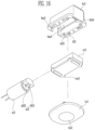
- FIG. 17 is a rear view of a tactile stimulation providing apparatus formed in the shape of an arm warmer in accordance with another embodiment of the present invention.
- FIG. 18 is a view illustrating a case where the size of the tactile stimulation providing apparatus shown in FIG. 17 is adjusted.
- FIG. 19 is a front view of a tactile stimulation providing apparatus formed in the form of a vest in accordance with another embodiment of the present invention.
- FIG. 20 is a rear view of the tactile stimulation providing apparatus shown in FIG. 19 .
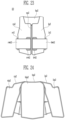
- FIG. 21 is a view illustrating a case where the size of the tactile stimulation providing apparatus shown in FIG. 19 is adjusted in a first step.
- FIG. 22 is a view illustrating a case where the size of the tactile stimulation providing apparatus shown in FIG. 19 is adjusted in a second step.
- FIG. 23 is a view illustrating a state in which the tactile stimulation providing apparatus shown in FIG. 19 is two-step adjusted to be worn by a user.
- FIG. 24 is a view illustrating a case where front panels of the tactile stimulation providing apparatus shown in FIG. 19 are unfolded.
- FIG. 25 is a view illustrating a case where inside skins are removed in the state shown in FIG. 24 .
- FIG. 26 is a view illustrating one surfaces of base bands separated in the state shown in FIG. 25 .
- FIG. 27 is a front view of a tactile stimulation providing apparatus formed in the form of a vest in accordance with still another embodiment of the present invention.
- FIG. 28 is a rear view of the tactile stimulation providing apparatus shown in FIG. 27 .
- FIGS. 29 and 30 are views illustrating a process in which a user wears the tactile stimulation providing apparatus shown in FIG. 27 .
- FIGS. 31 and 32 are views illustrating a modification of the tactile stimulation providing apparatus shown in FIG. 27 .
- FIGS. 33 and 34 are views illustrating another modification of the tactile stimulation providing apparatus shown in FIG. 27 .
- FIG. 1 is a view illustrating an actuator case at a point of view in accordance with an embodiment of the present invention
- FIG. 2 is a view illustrating the actuator case shown in FIG. 1 at another point of view.
- the actuator case 1 in accordance with the embodiment of the present invention may include a bottom case bc 1 , a cover case cc 1 , and a top case tc 1 .
- a position relationship of the bottom case bc 1 , the cover case cc 1 , and the top case tc 1 may be determined based on a base band.
- the base band may be located between the cover case cc 1 and the top case tc 1 .
- a relative position relationship of the base band and the actuator case 1 will be described with reference to FIGS. 3 and 4 .
- An actuator ac 1 is located on one surface of the base band, and includes a driver mb 1 and an eccentric mass em 1 .
- the driver mb 1 and the eccentric mass em 1 may be rotatably connected through a shaft.
- the actuator ac 1 may be an eccentric rotation motor (ERM).
- the actuator ac 1 may generate a vibration when the eccentric mass em 1 rotated by the driver mb 1 serves as an imbalanced vibrator.
- the actuator ac 1 may be a cylindrical vibration motor that has a diameter of about 6 mm and has a total height of about 17 mm. While a coin-shaped motor generates a vibration in a horizontal direction when a vibrator is rotated horizontally, the actuator ac 1 of this embodiment may generate a vibration in a vertical direction.
- the bottom case bc 1 is located on the one surface of the base band, and includes a first accommodation part tha 1 for accommodating the driver mb 1 and a second accommodation part thb 1 for accommodating the eccentric mass em 1 . That is, the bottom case bc 1 may accommodate the whole or a portion of the actuator ac 1 except a line. In some embodiments, when the bottom case bc 1 accommodates only a portion of the actuator ac 1 , the other portion of the actuator ac 1 may be accommodated by the cover case cc 1 which will be described later.
- the cover case cc 1 is located on the one surface of the base band, and is coupled to the bottom case bc 1 to allow the driver mb 1 to be adhered closely to the first accommodation part tha 1 .
- the cover case cc 1 may be coupled to the bottom case bc 1 while covering the actuator ac 1 .
- a male fastening part cm 1 of the cover case cc 1 is fitted into a female fastening part bsf 1 of the bottom case bc 1 , so that the cover case cc 1 can be firmly fixed to the bottom case bc 1 .
- the first accommodation part tha 1 and an accommodation part chaff may be formed such that the driver mb 1 of the actuator ac 1 can be firmly fixed.
- the male fastening part cm 1 of the cover case cc 1 may protrude such that the cover case cc 1 is parallel to the surface on which the cover case cc 1 is in contact with the base band.
- four pairs of the male fastening parts cm 1 and the female fastening parts bsf 1 are provided.
- the number of the male fastening parts cm 1 and the female fastening parts bsf 1 may vary.
- the cover case cc 1 is coupled to the bottom case bc 1 , to form, along with the second accommodation part thb 1 , an extra rotating space of the eccentric mass em 1 while allowing the eccentric mass em 1 to be spaced apart from the one surface of the base band. That is, an accommodation part chb 1 of the cover case cc 1 is matched to the second accommodation part thb 1 , to form an extra rotating space that does not interfere with rotation of the eccentric mass em 1 . Also, the accommodation part chb 1 of the cover case cc 1 functions to allow the eccentric mass em 1 to be spaced apart from the one surface of the base band. Thus, even when the base band is made of a flexible cloth or rubber material, the eccentric mass em 1 can be reliably rotated without colliding with the base band.
- the top case tc 1 is located on the other surface of the base band, and allows the bottom case bc 1 to be fixed to the base band.
- a male fastening part tm 1 of the top case tc 1 penetrates the base band and is coupled to a female fastening part bf 1 , so that the actuator ac 1 and the actuator case 1 can be fixed to the base band.
- the base band may include an opening having a shape through which the male fastening part tm 1 can pass.
- an area of the top case tc 1 adhered closely to the other surface of the base band may be smaller than that of the bottom case bc 1 adhered closely to the one surface of the base band. Since a space in which the male fastening part tm 1 can be located is relatively insufficient, two pairs of the male fastening parts tm 1 and the female fastening parts bf 1 are provided in this embodiment.
- the top case tc 1 when the area of the top case tc 1 is smaller than that of the bottom case bc 1 , a distance between a plurality of top cases, on which vibrations of a plurality of actuators are concentrated is sufficient even though the plurality of actuators are densely arranged. Hence, a resolution of vibrations that a user actually feels can be increased. Also, in this embodiment, one surface of the top case tc 1 is configured in a circular shape, so that the user does not feel any corner, thereby providing more comfortable feeling.
- the bottom case bc 1 may include a protrusion part bm 1
- the top case tc 1 may include a recessed part tf 1 .
- the protrusion part bm 1 of the bottom case bc 1 is fitted into the recessed part tf 1 while pressurizing the base band, so that the actuator ac 1 and the actuator case 1 can be more firmly fixed to the base band.
- the area of the top case tc 1 is relatively small, four pairs of the protrusion parts bm 1 and the recessed parts tf 1 are provided.
- FIG. 3 is a front view of a tactile stimulation providing apparatus formed in the shape of an arm warmer in accordance with an embodiment of the present invention and FIG. 4 is a rear view of the tactile stimulation providing apparatus shown in FIG. 3 .
- the tactile stimulation providing apparatus 10 formed in the shape of an arm warmer in accordance with the embodiment of the present invention may include a base band 100 , a plurality of actuators, a plurality of bottom cases, a plurality of cover cases, and a plurality of top cases 500 c .
- the tactile stimulation providing apparatus 10 may selectively further include an auxiliary band 200 , a controller case 300 , a ring 400 , a controller, and a signal transmission member.
- the plurality of top cases 500 c may be located on a rear surface of the base band 100 .
- the plurality of bottom cases and the plurality of cover cases may be located on a front surface of the base band 100 .
- the plurality of bottom cases and the plurality of cover cases may be covered by a protective cover CV and detachable members 110 and 120 .
- Each of the plurality of actuators may be interposed between a corresponding bottom case and a corresponding cover case. Therefore, the base band 100 may support the plurality of actuators.
- a flexible material such as a cloth material, a mesh material, a rubber material, or neoprene may be used for the base band 100 . Since users have various shapes and sizes with respect to the same body part, comfortable wearing sensation can be provided to the users, when the flexible material is used for the base band 100 .
- the base band 100 may be configured in a single layer. However, in a preferred embodiment, the base band 100 may be configured in a plurality of layers. The plurality of layers may be made of different materials. For example, the rear surface of the base band 100 may be configured in a layer made of a mesh material, and the front surface of the base band 100 may be configured in a layer made of a neoprene material.
- the plurality of actuators may be located on the rear surface of the base band 100 , which is made of the mesh material.
- the mesh material does not propagate vibrations of the plurality of actuators, and does not interfere with movements of the plurality of actuators.
- the front surface of the base band 100 which is made of the neoprene material, can prevent vibrations generated from the plurality of actuators from reaching the controller case 300 .
- the detachable member 110 may be located on the front surface of the base band 100 .
- the detachable member 120 may be located at the other end of the front surface of the base band 100 to be spaced apart from the detachable member 110 , and be detachable from the detachable member 110 .
- the detachable member 110 may be a detachable member of type A
- the detachable member 120 may be a detachable member of type B.
- a detachable member may be of any one of the type A and the type B.
- the type A and the type B may be detachable from each other.
- the type A and the type A may not be detachable from each other.
- the type B and the type B may not be detachable from each other. All kinds of detachable members having these types may be used as the detachable member of this embodiment.
- Examples of the detachable member may be VELCRO® (a hook and loop fastener), a magnet, an electromagnet, a snap button, buckle, and the like.
- a case where the detachable member is VELCRO® (a hook and loop fastener) is assumed and illustrated in drawings of the following embodiments.
- An upper edge and a lower edge of the base band 100 may have a streamline shape.
- the unfolded shape of the base band 100 becomes a streamline shape such as a planar figure of a truncated cone, so that the base band 100 can be adhered more closely to an arm of a user when the base band 100 is rolled around the arm of the user.
- the auxiliary band 200 may include a detachable member (not shown) of the type B, which is detachable from the detachable member 110 on a rear surface thereof, and one end of the auxiliary band 200 may be connected to one end of the base band 100 .
- the auxiliary band 200 separates the controller case 300 from the base band 100 , so that vibrations of the plurality of actuators located at the base band 100 are not propagated to the controller case 300 , thereby preventing noise. Also, the auxiliary band 200 adjusts a relative attachment position of the detachable member on the rear surface thereof and the detachable member 100 , so that the position of the controller case 300 can be adjusted to fit a body type of a user.
- a detachable member 210 is located on a front surface of the auxiliary band 200 , and is detachable from the detachable member 120 .
- the detachable member 210 may be a detachable member of the type A.
- the detachable member 120 is detachable from not only the detachable member 110 but also the detachable member 210 , and accordingly, the tactile stimulation providing apparatus 10 can fit various body types of users.
- a width of the other end of the auxiliary band 200 may be greater than that of the inner circumference of an opening of the controller case 300 .
- the other end of the auxiliary band 200 may have a trumpet shape or hook shape.
- the controller case 300 is not easily escaped from the auxiliary band 200 .
- the ring 400 may be connected to the one end of the base band 100 .
- a width of the other end of the base band 100 may be greater than that of the inner circumference of the ring 400 .
- the other end of the base band 100 may have a trumpet shape or hook shape.
- the base band 100 maintains a state in which the other end of the base band 100 is caught by the ring 400 , so that a process in which a next user again inserts the other end of the base band 100 into the ring 400 when the next user wears the tactile stimulation providing apparatus 10 can be omitted. Since the base band 100 has elasticity, a user enables the other end of the base band 100 to pass through the ring 400 by bending the other end of the base band 100 , when the user wears the tactile stimulation providing apparatus 10 .
- the plurality of top cases 500 c may be exposed to the outside.
- the plurality of top cases 500 c exposed to the outside may be adhered closely to an arm of a user.
- Each of the plurality of top cases 500 c propagates a driving force of a corresponding actuator to a body of a user, so that the user can feel a tactile stimulation.
- the controller may be located in the controller case 300 , and generate a driving signal for controlling the plurality of actuators.
- the controller may include a microcontroller, a motor driver, a power management module, and the like.
- a separate battery for driving the controller may be located in the controller case 300 .
- the controller may be configured in the form of a PCB, an FPCB, an IC, etc.
- the controller may receive a tactile stimulation pattern input through the existing wireless communication techniques including Bluetooth, Wi-Fi, and the like or through the existing wired communication techniques.
- the tactile stimulation pattern may be a multidirectional tactile stimulation pattern.
- a separate memory device may be located in the controller case 300 .
- the signal transmission member may transmit a driving signal to the plurality of actuators from the controller.
- the signal transmission member may be configured with an FPCB or a material such as a wire.
- the signal transmission member may electrically connect the plurality of actuators to the controller.
- Each of the base band 100 , the auxiliary band 200 , and the controller case 300 may include an opening such that the signal transmission member passes therethrough.
- FIG. 5 is a view illustrating a point of view where a user is wearing the tactile stimulation providing apparatus shown in FIG. 3 .
- FIG. 5 illustrates in a state in which the tactile stimulation providing apparatus 10 is put on the body of the user, and one end of the tactile stimulation providing apparatus 10 , which includes the detachable member 120 , passes through the ring 400 .
- FIG. 6 is a view illustrating a point of view where a user has worn the tactile stimulation providing apparatus shown in FIG. 3 .
- the user attaches the detachable member 120 of the tactile stimulation providing apparatus 10 to the detachable member 210 , so that the tactile stimulation providing apparatus 10 is fixed to a body of the user.
- the detachable member 120 may be attached to the detachable member 110 .
- the detachable member 120 is attachable to the detachable member 110 or the detachable member 210 , to handle various bodies of users.
- FIG. 7 is a view illustrating the base band and the auxiliary band of the tactile stimulation providing apparatus shown in FIG. 3 .
- FIG. 7 a state in which the controller case 300 is removed as compared with FIG. 3 is illustrated.
- the auxiliary band 200 may include an opening 220 into which the signal transmission member is inserted.
- the base band 100 may include an opening into which the signal transmission member is inserted, even though the opening is not shown in FIG. 7 since it is covered by the auxiliary band 200 .
- the openings may have sizes and positions, which are approximately similar to each other.
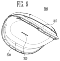
- FIG. 8 is a view illustrating the controller case of the tactile stimulation providing apparatus shown in FIG. 3 at a point of view and
- FIG. 9 is a view illustrating the controller case shown in FIG. 8 at another point of view.
- the controller case 300 may include openings 310 and 320 into which the auxiliary band 200 is inserted. Also, the controller case 300 may further include an opening 330 into which the signal transmission member is inserted.
- a lower surface of the controller case 300 may be concavely formed to be adhered closely to an arm of a user. That is, the controller case 300 may have a curvature suitable for a curve of a body of the user, which is to be designed.
- FIG. 10 is a view illustrating an actuator case at a point of view in accordance with another embodiment of the present invention and FIG. 11 is a view illustrating the actuator case shown in FIG. 10 at another point of view.
- the actuator case 2 in accordance with another embodiment of the present invention may include a bottom case bc 2 , a cover case cc 2 , and a top case tc 2 .
- a position relationship of the bottom case bc 2 , the cover case cc 2 , and the top case tc 2 may be determined based on a base band.
- the base band may be located between the cover case cc 2 and the top case tc 2 .
- a relative position relationship of the base band and the actuator case 2 will be described with reference to FIGS. 12 to 14 .
- An actuator ac 2 is located on one surface of the base band, and includes a driver mb 2 and an eccentric mass em 2 .
- the driver mb 2 and the eccentric mass em 2 may be rotatably connected through a shaft.
- the actuator ac 2 may be an ERM.
- the actuator ac 2 may generate a vibration when the eccentric mass em 2 rotated by the driver mb 2 serves as an imbalanced vibrator.
- the actuator ac 2 may be a cylindrical vibration motor that has a diameter of about 6 mm and has a total height of about 17 mm. While a coin-shaped motor generates a vibration in a horizontal direction when a vibrator is rotated horizontally, the actuator ac 2 of this embodiment may generate a vibration in a vertical direction.
- the bottom case bc 2 is located on the one surface of the base band, and includes a first accommodation part tha 2 for accommodating the driver mb 2 and a second accommodation part thb 2 for accommodating the eccentric mass em 2 . That is, the bottom case bc 2 may accommodate the whole or a portion of the actuator ac 2 except a line. In some embodiments, when the bottom case bc 2 accommodates only a portion of the actuator ac 2 , the other portion of the actuator ac 2 may be accommodated by the cover case cc 2 which will be described later.
- the cover case cc 2 is located on the one surface of the base band, and is coupled to the bottom case bc 2 to allow the driver mb 2 to be adhered closely to the first accommodation part tha 2 .
- the cover case cc 2 may be coupled to the bottom case bc 2 while covering the actuator ac 2 .
- a male fastening part cm 2 of the cover case cc 2 is fitted into a female fastening part bsf 2 of the bottom case bc 2 , so that the cover case cc 2 can be firmly fixed to the bottom case bc 2 .
- the first accommodation part tha 2 and an accommodation part chat may be formed such that the driver mb 2 of the actuator ac 2 can be firmly fixed.
- the male fastening part cm 2 of the cover case cc 2 may protrude such that the cover case cc 2 is parallel to the surface on which the cover case cc 2 is in contact with the base band.
- four pairs of the male fastening parts cm 2 and the female fastening parts bsf 2 are provided.
- the number of the male fastening parts cm 2 and the female fastening parts bsf 2 may vary.
- the cover case cc 2 is coupled to the bottom case bc 2 , to form, along with the second accommodation part thb 2 , an extra rotating space of the eccentric mass em 2 while allowing the eccentric mass em 2 to be spaced apart from the one surface of the base band. That is, an accommodation part chb 2 of the cover case cc 2 is matched to the second accommodation part thb 2 , to form an extra rotating space that does not interfere with rotation of the eccentric mass em 2 . Also, the accommodation part chb 2 of the cover case cc 2 functions to allow the eccentric mass em 2 to be spaced apart from the one surface of the base band. Thus, even when the base band is made of a flexible cloth or rubber material, the eccentric mass em 2 can be reliably rotated without colliding with the base band.
- the top case tc 2 is located on the other surface of the base band, and allows the bottom case bc 2 to be fixed to the base band.
- a male fastening part tm 2 of the top case tc 2 penetrates the base band and is coupled to a female fastening part bf 2 , so that the actuator ac 2 and the actuator case 2 can be fixed to the base band.
- the base band may include an opening having a shape through which the male fastening part tm 2 can pass.
- an area of the top case tc 2 adhered closely to the other surface of the base band may correspond to that of the bottom case bc 2 adhered closely to the one surface of the base band. Since a space in which the male fastening part tm 2 can be located is relatively sufficient, four pairs of the male fastening parts tm 2 and the female fastening parts bf 2 are provided in this embodiment.
- the actuator ac 2 is more strongly vibrated, this can be endured.
- the area of the top case tc 2 corresponds to that of the bottom case bc 2 , a sufficient vibration force is propagated to a back of a user, which is relatively less sensitive, so that the user can more surely feel a vibration.
- a corner of one surface of the top case tc 2 is formed round, so that more comfortable feeling can be provided to the user.
- the bottom case bc 2 may include a protrusion part bm 2
- the top case tc 2 may include a recessed part tf 2
- the protrusion part bm 2 of the bottom case bc 2 is fitted into the recessed part tf 2 while pressurizing the base band, so that the actuator ac 2 and the actuator case 2 can be more firmly fixed to the base band.
- the area of the top case tc 2 is relatively sufficient, six pairs of the protrusion parts bm 2 and the recessed parts tf 2 are provided, so that a sufficient supporting force can be provided.
- FIG. 12 is a front view of a tactile stimulation providing apparatus formed in the form of a vest in accordance with an embodiment of the present invention
- FIG. 13 is a rear view of the tactile stimulation providing apparatus shown in FIG. 12
- FIG. 14 is a view illustrating a case where front panels of the tactile stimulation providing apparatus shown in FIG. 12 are unfolded.
- the tactile stimulation providing apparatus 21 may include a first front panel rp 1 , a second front panel lp 1 , and a rear panel bp 1 .
- Each of the panels rp 1 , lp 1 , and bp 1 may be configured with a plurality of layers, and at least one layer among the plurality of layers may correspond to a base band.
- One surface of the base band may be located in the panel not to be seen. The other surface of the base band may be exposed to the inside with reference to FIG. 14 .
- the first front panel rp 1 may include a plurality of actuators arranged between one side and the other side thereof.
- the second front panel lp 1 may include a plurality of actuators arranged between one side and the other side thereof.
- the one side of the second front panel lp 1 may be fastened to the other side of the first front panel rp 1 .
- the one side of the second front panel lp 1 and the other side of the first front panel rp 1 may be fastened to each other through a zipper, VELCRO® (a hook and loop fastener), a buckle, or a button.
- the rear panel bp 1 may include a plurality of actuators arranged between one side and the other side thereof.
- the one side of the rear panel bp 1 may be fastened to the one side of the first front panel rp 1
- the other side of the rear panel bp 1 may be fastened to the other side of the second front panel lp 1 .
- the rear panel bp 1 may include a first ring rr 1 connected to the one side thereof and a second ring lr 1 connected to the other side thereof.
- the first front panel rp 1 may Include a first wing band rwb 1 connected to the one side thereof.
- the second front panel lp 1 may include a second wing band lwb 1 connected to the other side thereof.
- a detachable member rv 21 may be located at one end of a front surface of the first wing band rwb 1 .
- a detachable member rv 11 may be located on a front surface of the first front panel rp 1 , and be detachable from the detachable member rv 21 .
- a detachable member lv 21 may be located at one end of a front surface of the second wing band lwb 1 .
- a detachable member lv 11 may be located on a front surface of the second front panel lp 1 , and be detachable from the detachable member lv 21 .
- a user allows one end of the first wing band rwb 1 to pass through the first ring rr 1 and then pulls the first wing band rwb 1 to fit a body size of the user, and attaches the detachable member rv 21 to the detachable member rv 11 , so that the first front panel rp 1 can be adhered closely to a torso of the user.
- the user allows one end of the second wing band lwb 1 to pass through the second ring lr 1 and then pulls the second wing band lwb 1 to fit the body size of the user, and attaches the detachable member lv 21 to the detachable member lv 11 , so that the second front panel lp 1 can be adhered closely to the torso of the user.
- a width of the one end of the first wing band rwb 1 may be greater than that of the inner circumference of the first ring rr 1
- a width of the one end of the second wing band lwb 1 may be greater than that of the inner circumference of the second ring lr 1
- the one end of the first wing band rwb 1 and the one end of the second wing band lwb 1 may have a trumpet shape or hook shape.
- the one ends of the wing bands rwb 1 and lwb 1 maintain a state in which they are caught by the respective rings rr 1 and lr 1 , so that a process in which a next user again inserts the wing bands rwb 1 and lwb 1 into the respective rings rr 1 and lr 1 when the next user wears the tactile stimulation providing apparatus 21 can be omitted.
- the rear panel bp 1 may further include a pocket bpp 1 for keeping a battery or other usages.
- An opening may be formed at a portion of the pocket bpp 1 such that an electric wire of a battery can extend to the inside of the panels lp 1 , rp 1 , and bp 1 .
- a controller may use an internal battery. Therefore, the pocket bpp 1 may be unnecessary.
- each of the first front panel rp 1 , the rear panel bp 1 , and the second front panel lp 1 of the tactile stimulation providing apparatus 21 in accordance with the another embodiment of the present invention may include a plurality of actuators.
- a plurality of top cases tcr 1 of the first front panel rp 1 , a plurality of top cases tcb 1 of the rear panel bp 1 , and a plurality of top cases tcl 1 of the second front panel lp 1 may be exposed.
- the plurality of top cases tcr 1 , tcb 1 , and tcl 1 may be adhered closely to a torso of a user, when the tactile stimulation providing apparatus 21 is tightened around the torso of the user by the wing bands lwb 1 and rwb 1 , the detachable members rv 11 , rv 21 , lv 11 , and lv 21 , and the rings lr 1 and rr 1 .
- the user can strongly feel vibrations of the plurality of actuators built in the plurality of top cases tcr 1 , tcb 1 , and tcl 1 through the plurality of top cases tcr 1 , tcb 1 , and tcl 1 adhered closely to the torso of the user.
- inside skins severing as linings of the panels rp 1 , bp 1 , and lp 1 may cover the plurality of top cases tcr 1 , tcb 1 , and tcl 1 such that the plurality of top cases tcr 1 , tcb 1 , and tcl 1 are not exposed to the outside.
- the first front panel rp 1 may be elastically connected to the rear panel bp 1 through a connection band rcb 1 .
- the second front panel lp 1 may be elastically connected to the rear panel bp 1 through a connection band 1 cb 1 .
- FIG. 15 is a view illustrating an actuator case at a point of view in accordance with still another embodiment of the present invention and FIG. 16 is a view illustrating the actuator case shown in FIG. 15 at another point of view.
- the actuator case 3 in accordance with the still another embodiment of the present invention may include a bottom case bc 3 , a cover case cc 3 , and a top case tc 3 .
- a position relationship of the bottom case bc 3 , the cover case cc 3 , and the top case tc 3 may be determined based on a base band.
- the base band may be located between the cover case cc 3 and the top case tc 3 .
- An actuator ac 3 is located on one surface of the base band, and includes a driver mb 3 and an eccentric mass em 3 .
- the driver mb 3 and the eccentric mass em 3 may be rotatably connected through a shaft.
- the actuator ac 3 may be an ERM.
- the actuator ac 3 may generate a vibration when the eccentric mass em 3 rotated by the driver mb 3 serves as an imbalanced vibrator.
- the actuator ac 3 may be a cylindrical vibration motor that has a diameter of about 6 mm and has a total height of about 17 mm. While a coin-shaped motor generates a vibration in a horizontal direction when a vibrator is rotated horizontally, the actuator ac 3 of this embodiment may generate a vibration in a vertical direction.
- the bottom case bc 3 is located on the one surface of the base band, and includes a first accommodation part tha 3 for accommodating the driver mb 3 and a second accommodation part thb 3 for accommodating the eccentric mass em 3 . That is, the bottom case bc 3 may accommodate the whole or a portion of the actuator ac 3 except a line. In some embodiments, when the bottom case bc 3 accommodates only a portion of the actuator ac 3 , the other portion of the actuator ac 3 may be accommodated by the cover case cc 3 which will be described later.
- the cover case cc 3 is located on the one surface of the base band, and is coupled to the bottom case bc 3 to allow the driver mb 3 to be adhered closely to the first accommodation part tha 3 .
- the cover case cc 3 may be coupled to the bottom case bc 3 while covering the actuator ac 3 .
- a male fastening part cm 3 of the cover case cc 3 is fitted into a female fastening part bsf 3 of the bottom case bc 3 , so that the cover case cc 3 can be firmly fixed to the bottom case bc 3 .
- the first accommodation part tha 3 and an accommodation part cha 3 may be formed such that the driver mb 3 of the actuator ac 3 can be firmly fixed.
- the male fastening part cm 3 of the cover case cc 3 may protrude such that the cover case cc 3 is parallel to the surface on which the cover case cc 3 is in contact with the base band.
- four pairs of the male fastening parts cm 3 and the female fastening parts bsf 3 are provided.
- the number of the male fastening parts cm 3 and the female fastening parts bsf 3 may vary.
- the actuator ac 3 may further include a spacer ar 3 that covers at least a portion of the driver mb 3 and is interposed between the driver mb 3 and the first accommodation part tha 3 .
- the spacer ar 3 may have a cylindrical shape surrounding the outer circumference of the driver mb 3 .
- the spacer ar 3 may allow the driver mb 3 , the first accommodation part tha 3 , and the accommodation part cha 3 to be spaced apart from each other.
- the spacer ar 3 may be made of an elastic material such as rubber, silicon, polyurethane, or sponge.
- a gap may occur between the driver mb 3 , the first accommodation part tha 3 , and the accommodation part cha 3 due to a process variation, and hence the spacer ar 3 prevents noise that may occur due to the process variation. Also, the spacer ar 3 may prevent noise that may occur in the actuator ac 3 since a load where each actuator ac 3 is to be vibrated is not constant.
- the cover case cc 3 is coupled to the bottom case bc 3 , to form, along with the second accommodation part thb 3 , an extra rotating space of the eccentric mass em 3 while allowing the eccentric mass em 3 to be spaced apart from the one surface of the base band. That is, an accommodation part chb 3 of the cover case cc 3 is matched to the second accommodation part thb 3 , to form an extra rotating space that does not interfere with rotation of the eccentric mass em 3 . Also, the accommodation part chb 3 of the cover case cc 3 functions to allow the eccentric mass em 3 to be spaced apart from the one surface of the base band. Thus, even when the base band is made of a flexible cloth or rubber material, the eccentric mass em 3 can be reliably rotated without colliding with the base band.
- the top case tc 3 is located on the other surface of the base band, and allows the bottom case bc 3 to be fixed to the base band.
- a male fastening part tm 3 of the top case tc 3 penetrates the base band and is coupled to a female fastening part bf 3 , so that the actuator ac 3 and the actuator case 3 can be fixed to the base band.
- the base band may include an opening having a shape through which the male fastening part tm 3 can pass.
- an area of the top case tc 3 adhered closely to the other surface of the base band may correspond to that of the bottom case bc 3 adhered closely to the one surface of the base band. Since a space in which the male fastening part tm 3 can be located is relatively sufficient, four pairs of the male fastening parts tm 3 and the female fastening parts bf 3 are provided in this embodiment.
- an upper surface tts 3 of the top case tc 3 shown in FIG. 16 has a narrow area, so that a locally concentrated vibration force can be propagated to a body of a user.
- the top case tc 3 may be formed in the shape of a truncated cone.
- the bottom case bc 3 may include a protrusion part bm 3
- the top case tc 3 may include a recessed part tf 3 .
- the protrusion part bm 3 of the bottom case bc 3 is fitted into the recessed part tf 3 while pressurizing the base band, so that the actuator ac 3 and the actuator case 3 can be more firmly fixed to the base band.
- the area of a lower surface of the top case tc 3 is relatively sufficient, six pairs of the protrusion parts bm 3 and the recessed parts tf 3 are provided, so that a sufficient supporting force can be provided.
- FIG. 17 is a rear view of a tactile stimulation providing apparatus formed in the shape of an arm warmer in accordance with another embodiment of the present invention and FIG. 18 is a view illustrating a case where the size of the tactile stimulation providing apparatus shown in FIG. 17 is adjusted.
- the tactile stimulation providing apparatus 10 ′ shown in FIG. 17 may further include a detachable member 130 , as compared with the tactile stimulation providing apparatus 10 .
- the detachable member 130 may be located at the other end of the rear surface of the base band 100 , and be detachable from a detachable member 110 ′ (see FIG. 18 ).
- the detachable member 130 may be a detachable member of the type B.
- the other end of the base band 100 is folded, so that the detachable member 110 ′ and the detachable member 120 can be attached and fixed to each other.
- a length of the other end of the tactile stimulation providing apparatus 10 ′ becomes shorter than that of the other end of the tactile stimulation providing apparatus 10 shown in FIG. 4 .
- the detachable member 130 substitutes of functions of the detachable member 120 .
- this state may be useful for people having thin wrists, such as women.
- the tactile stimulation providing apparatus 10 ′ may include the detachable member 110 ′ having an area wider than that of the detachable member 110 of the tactile stimulation providing apparatus 10 shown in FIG. 4 .
- the detachable member 110 ′ may be located in the entire region of the front surface of the base band 100 except a region in which the detachable member 120 is located.
- the protective cover CV shown in FIG. 4 may not exist in the tactile stimulation providing apparatus 10 ′.
- the detachable member 110 ′ may serve as the protective cover CV.
- the detachable member 110 ′ having a widened area may provide an extra region in which the detachable member on the rear surface of the auxiliary band 200 can be detachable.
- the tactile stimulation providing apparatus 10 ′ can handle various bodies of users.
- the other configuration of the tactile stimulation providing apparatus 10 ′ is substantially identical or similar to that of the tactile stimulation providing apparatus 10 , and therefore, overlapping descriptions will be omitted.
- FIG. 19 is a front view of a tactile stimulation providing apparatus formed in the form of a vest in accordance with another embodiment of the present invention and FIG. 20 is a rear view of the tactile stimulation providing apparatus shown in FIG. 19 .
- the tactile stimulation providing apparatus 22 may include a first front panel rp 2 , a second front panel lp 2 , and a rear panel bp 2 .
- Each of the panels rp 2 , lp 2 , and bp 2 may be configured with a plurality of layers, and at least one layer among the plurality of layers may correspond to a base band.
- the first front panel rp 2 may include a plurality of actuators arranged between one side and the other side thereof.
- the second front panel lp 2 may include a plurality of actuators arranged between one side and the other side thereof.
- the one side of the second front panel lp 2 may be fastened to the other side of the first front panel rp 2 .
- the one side of the second front panel lp 2 and the other side of the first front panel rp 2 may be fastened to each other through a fastening member zp 2 such as a zipper, VELCRO® (a hook and loop fastener), a buckle, or a button.
- the rear panel bp 2 may include a plurality of actuators arranged between one side and the other side thereof.
- the one side of the rear panel bp 2 may be fastened to the one side of the first front panel rp 2
- the other side of the rear panel bp 2 may be fastened to the other side of the second front panel lp 2 .
- the rear panel bp 2 may include a first ring rr 2 connected to the one side thereof and a second ring lr 2 connected to the other side thereof.
- the first front panel rp 2 may include a first wing band rwb 2 connected to the one side thereof.
- the second front panel lp 2 may include a second wing band lwb 2 connected to the other side thereof.
- a detachable member rv 22 may be located at one end of a front surface of the first wing band rwb 2 .
- a detachable member rv 12 may be located on a front surface of the first front panel rp 2 , and be detachable from the detachable member rv 22 .
- the detachable member rv 12 may extend from the front surface of the first front panel rp 2 to be located on the front surface of the first wing band rwb 2 .
- An extending portion of the detachable member rv 12 may be used such that detachable members rv 22 and rv 42 are attached thereto.
- a detachable member lv 22 may be located at one end of a front surface of the second wing band lwb 2 .
- a detachable member lv 12 may be located on a front surface of the second front panel lp 2 , and be detachable from the detachable member lv 22 .
- the detachable member lv 12 may extend from the front surface of the second front panel lp 2 to be located on the front surface of the second wing band lwb 2 .
- An extending portion of the detachable member lv 12 may be used such that detachable members lv 22 and lv 42 are attached thereto.
- the detachable members rv 22 and lv 22 may be detachable members of the type B, and the detachable members rv 12 and lv 12 may be detachable members of the type A.
- a user allows one end of the first wing band rwb 2 to pass through the first ring rr 2 and then pulls the first wing band rwb 2 to fit a body size of the user, and attaches the detachable member rv 22 to the detachable member rv 12 , so that the first front panel rp 2 can be adhered closely to a torso of the user.
- the user allows one end of the second wing band lwb 2 to pass through the second ring lr 2 and then pulls the second wing band lwb 2 to fit the body size of the user, and attaches the detachable member lv 22 to the detachable member lv 12 , so that the second front panel lp 2 can be adhered closely to the torso of the user.
- a width of the one end of the first wing band rwb 2 may be greater than that of the inner circumference of the first ring rr 2
- a width of the one end of the second wing band lwb 2 may be greater than that of the inner circumference of the second ring lr 2
- the one end of the first wing band rwb 2 and the one end of the second wing band lwb 2 may have a trumpet shape or hook shape.
- the one ends of the wing bands rwb 2 and lwb 2 maintain a state in which they are caught by the respective rings rr 2 and lr 2 , so that a process in which a next user again inserts the wing bands rwb 2 and lwb 2 into the respective rings rr 2 and lr 2 when the next user wears the tactile stimulation providing apparatus 22 can be omitted.
- the tactile stimulation providing apparatus 22 may further include detachable members rv 42 , rv 32 , lv 42 , and lv 32 , as compared with the tactile stimulation providing apparatus 21 shown in FIG. 12 .
- a detachable member rv 42 may be located at one end of a rear surface of the first wing band rwb 2 , and be detachable from the detachable member rv 12 .
- the detachable member rv 42 may be a detachable member of the type B.
- a detachable member lv 42 may be located at one end of a rear surface of the second wing band lwb 2 , and be detachable from the detachable member lv 12 .
- the detachable member lv 42 may be a detachable member of the type B.
- a detachable member rv 32 may be located between the detachable member rv 42 and the other end of the first wing band rwb 2 on the rear surface of the first wing band rwb 2 , and be detachable from the detachable member rv 12 .
- the detachable member rv 32 may be a detachable member of the type B.
- a detachable member lv 32 may be located between the detachable member lv 42 and the other end of the second wing band lwb 2 on the rear surface of the second wing band lwb 2 , and be detachable from the detachable member lv 12 .
- the detachable member lv 32 may be a detachable member of the type B.
- a controller pocket mcp 2 for accommodating a controller case mc 2 and a battery pocket btp 2 for accommodating a battery bt 2 may be located on a rear surface of the rear panel bp 2 .
- a line pocket cbp 2 through which a line connecting a controller in the controller case mc 2 and the battery bt 2 passes may be further located on the rear surface of the rear panel bp 2 .
- a battery may be located in the controller case mc 2 . Therefore, the battery pocket btp 2 and the line pocket cbp 2 may be unnecessary.
- FIG. 21 is a view illustrating a case where the size of the tactile stimulation providing apparatus shown in FIG. 19 is adjusted in a first step.
- the detachable member rv 22 is attached to the detachable member rv 12 .
- the detachable member rv 42 may serve as the existing detachable member rv 22 . That is, a user allows one end of the first wing band rwb 2 to pass through the first ring rr 2 and then pulls the first wing band rwb 2 to fit a body size of the user, and attaches the detachable member rv 42 to the detachable member rv 12 , so that the first front panel rp 2 can be adhered closely to a torso of the user.
- FIG. 22 is a view illustrating a case where the size of the tactile stimulation providing apparatus shown in FIG. 19 is adjusted in a second step.
- the detachable member rv 42 is attached to the detachable member rv 12 .
- the detachable member rv 32 may serve as the existing detachable member rv 22 . That is, a user allows one end of the first wing band rwb 2 to pass through the first ring rr 2 and then pulls the first wing band rwb 2 to fit a body size of the user, and attaches the detachable member rv 32 to the detachable member rv 12 , so that the first front panel rp 2 can be adhered closely to a torso of the user.
- FIG. 23 is a view illustrating a state in which the tactile stimulation providing apparatus shown in FIG. 19 is two-step adjusted to be worn by a user.
- end portions of the wing bands rwb 2 and lwb 2 do not cross the fastening member zp 2 . That is, in accordance with the embodiments shown in FIGS. 21 to 23 , the first wing band rwb 2 can be prevented from being attached to the detachable member lv 12 while crossing the fastening member zp 2 , and the second wing band lwb 2 can be prevented from being attached to the detachable member rv 12 while crossing the fastening member zp 2 .
- FIG. 24 is a view illustrating a case where the front panels of the tactile stimulation providing apparatus shown in FIG. 19 are unfolded.
- the tactile stimulation providing apparatus 22 may include a first inside skin rip 2 , a second inside skin lip 2 , and a third inside skin bip 2 .
- the first to third inside skins rip 2 , lip 2 , and bip 2 may be made of a waterproof material.
- the first to third inside skins rip 2 , lip 2 , and bip 2 may be made of a material having excellent hygroscopicity and air permeability, such as a mesh.
- the first inside skin rip 2 may be located on a rear surface of the first front panel rp 2 .
- the first inside skin rip 2 may be detachable from the rear surface of the first front panel rp 2 through a detachable member.
- the second inside skin lip 2 may be located on a rear surface of the second front panel lp 2 .
- the second inside skin lip 2 may be detachable from the rear surface of the second front panel lp 2 through a detachable member.
- the third inside skin bip 2 may be located on a rear surface of the rear panel bp 2 .
- the third inside skin bip 2 may be detachable from the rear surface of the rear panel bp 2 through a detachable member.
- the first to third inside skins rip 2 , lip 2 , and bip 2 are replaced or cleaned, so that a plurality of users can use the tactile stimulation providing apparatus 22 without displeasure.
- FIG. 25 is a view illustrating a case where the inside skins are removed in the state shown in FIG. 24 .
- a plurality of top cases tcr 2 may be arranged on the other surface of a first base band rbb 2 of the first front panel rp 2 .
- a plurality of top cases tcl 2 may be arranged on the other surface of a second base band lbb 2 of the second front panel lp 2 .
- a plurality of top cases tcb 2 may be arranged on the other surface of a third base band bbb 2 of the rear panel bp 2 .
- FIG. 26 is a view illustrating one surfaces of the base bands separated in the state shown in FIG. 25 .
- the base bands rbb 2 , lbb 2 , and bbb 2 are separated from the tactile stimulation providing apparatus 22 , and one surfaces of the base bands rbb 2 , lbb 2 , and bbb 2 are illustrated.
- a plurality of bottom cases bcr 2 may be arranged on the one surface of the first base band rbb 2
- a plurality of bottom cases bcl 2 may be arranged on the one surface of the second base band lbb 2
- a plurality of bottom cases bcb 2 may be arranged on the one surface of the third base band bbb 2 .
- a plurality of cover cases may be located between the plurality of top cases tcr 2 , tcl 2 , and tcb 2 and the plurality of bottom cases bcr 2 , bcl 2 , and bcb 2 .
- a plurality of actuators may be located between the plurality of cover cases and the plurality of bottom cases bcr 2 , bcl 2 , and bcb 2 .
- Each actuator may require at least two or three channels (i.e., lines) to receive a ground voltage GND, a driving voltage VDD, a control signal, etc.
- lines may be easily damaged.
- a rigid line cover may be inserted so as to prevent damage of the lines, but a user may feel inconvenience.
- the plurality of actuators may be grouped, actuators of one group may be electrically connected to a sub-FPCB sfpcb 2 through lines sw 2 , and each sub-FPCB sfcb 2 may be electrically connected to a corresponding sub-PCB spcb 2 .
- the sub-PCB spcb 2 may be connected to a controller through a line.
- the sub-PCB spcb 2 may perform wired communication with the controller in a scheme such as RS232, USB, I2C, or SPI.
- the sub-PCB spcb 2 may perform wireless communication with the controller in a scheme such as Bluetooth, WIFI, or Zigbee.
- the line structure of the actuators can be simplified.
- FIG. 27 is a front view of a tactile stimulation providing apparatus formed in the form of a vest in accordance with still another embodiment of the present invention and FIG. 28 is a rear view of the tactile stimulation providing apparatus shown in FIG. 27 .
- the tactile stimulation providing apparatus 23 may include a first front panel rp 3 , a second front panel lp 3 , and a rear panel bp 3 .
- Each of the panels rp 3 , lp 3 , and bp 3 may be configured with a plurality of layers, and at least one layer among the plurality of layers may correspond to a base band.
- the first front panel rp 3 may include a plurality of actuators arranged between one side and the other side thereof.
- the second front panel lp 3 may include a plurality of actuators arranged between one side and the other side thereof.
- the one side of the second front panel lp 3 may be fastened to the other side of the first front panel rp 3 .
- the one side of the second front panel lp 3 and the other side of the first front panel rp 3 may be fastened to each other through a fastening member zp 3 such as a zipper, VELCRO® (a hook and loop fastener), a buckle, or a button.
- the rear panel bp 3 may include a plurality of actuators arranged between one side and the other side thereof.
- the one side of the rear panel bp 3 may be fastened to the one side of the first front panel rp 3
- the other side of the rear panel bp 3 may be fastened to the other side of the second front panel lp 3 .
- the rear panel bp 3 may include a first wing band rwb 3 connected to the one side thereof and a second wing band lwb 3 connected to the other side thereof.
- the first front panel rp 3 may include a first ring rr 3 connected to the one side thereof.
- the second front panel lp 3 may include a second ring lr 3 connected to the other side thereof.
- the first wing band rwb 3 may include a detachable member rv 43 located at one end of a rear surface thereof and a detachable member rv 33 located between the detachable member rv 43 and the other end of the first wing band rwb 3 .
- the second wing band lwb 3 may include detachable members lv 13 and lv 23 located on a front surface thereof, a detachable member lv 43 located at one end of a rear surface thereof, and a detachable member lv 33 located between the detachable member lv 43 and the other end of the second wing band lwb 3 .
- the rear panel bp 3 may include a detachable member bv 3 located on a rear surface thereof.
- the detachable member lv 43 may be detachable from the detachable member bv 3 .
- the detachable member rv 43 may be detachable from the detachable members lv 13 , lv 23 , and bv 3 .
- the detachable members lv 13 , lv 23 , lv 33 , bv 3 , and rv 33 may be detachable members of the type A
- the detachable members lv 43 and rv 43 may be detachable members of the type B.
- a width of one end of the first wing band rwb 3 may be greater than that of the inner circumference of the first ring rr 3
- a width of one end of the second wing band lwb 3 may be greater than that of the inner circumference of the second ring lr 3
- the one end of the first wing band rwb 3 and the one end of the second wing band lwb 3 may have a trumpet shape or hook shape.
- the one ends of the wing bands rwb 3 and lwb 3 maintain a state in which they are caught by the respective rings rr 3 and lr 3 , so that a process in which a next user again inserts the wing bands rwb 3 and lwb 3 into the respective rings rr 3 and lr 3 when the next user wears the tactile stimulation providing apparatus 23 can be omitted.
- a controller pocket mcp 3 for accommodating a controller case mc 3 and a battery pocket btp 3 for accommodating a battery bt 3 may be located on a rear surface of the rear panel bp 3 .
- any line pocket may not separately exist so as to secure a region for the detachable member bv 3 .
- a battery may be located in the controller case mc 3 . Therefore, the battery pocket btp 3 may be unnecessary.
- FIGS. 29 and 30 are views illustrating a process in which a user wears the tactile stimulation providing apparatus shown in FIG. 27 .
- the user may allow the one end of the second wing band lwb 3 to pass through the second ring lr 3 and then pull the second wing band lwb 3 to fit a body size of the user, and attach the detachable member lv 43 to at least one of the detachable members lv 33 , bv 3 , and rv 33 .
- the user may allow the one end of the first wing band rwb 3 to pass through the first ring rr 3 and then pull the first wing band rwb 3 to fit the body size of the user, and attach the detachable member rv 43 to at least one of the detachable members lv 23 , lv 23 , bv 3 , and rv 33 .
- any detachable member does not exist on front surfaces of the front panels rp 3 and lp 3 , aesthetic impression can be improved.
- the wing bands rwb 3 and lwb 3 do not overlap with the fastening member zp 3 in the tactile stimulation providing apparatus 23 even when the wing bands rwb 3 and lwb 3 are not folded, so that the tactile stimulation providing apparatus 23 can be easily detachable.
- a front surface of the tactile stimulation providing apparatus 23 may have a streamline shape when the user wears the tactile stimulation providing apparatus 23 , and a rear surface of the tactile stimulation providing apparatus 23 may be flat.
- the wing bands rwb 3 and lwb 3 are attached to the rear surface of the tactile stimulation providing apparatus 23 .
- FIGS. 31 and 32 are views illustrating a modification of the tactile stimulation providing apparatus shown in FIG. 27 .
- the rear panel bp 3 of the tactile stimulation providing apparatus 23 ′ may further include protrusion parts brs 3 and bls 3 .
- the protrusion parts brs 3 and bls 3 may be located corresponding to shoulder parts of a user.
- a detachable member rv 63 may be located on one surface of the protrusion part brs 3 .
- a detachable member lv 63 may be located on one surface of the protrusion part bls 3 .
- the first front panel rp 3 may include a detachable member rv 53 located corresponding to a shoulder part of the user.
- the second front panel lp 3 may include a detachable member lv 53 located corresponding to a shoulder part of the user.
- detachable members rv 63 and lv 63 may be detachable members of the type B, and detachable member rv 53 and lv 53 may be detachable members of the type A.
- the tactile stimulation providing apparatus 23 is well adhered closely to a waist of the user due to the wing bands rwb 3 and lwb 3 , but may not well adhered closely to the shoulder parts and a chest part of the user. However, when the positions of the wing bands rwb 3 and lwb 3 are simply changed to the chest part or when the widths of the wing bands rwb 3 and lwb 3 are widened, the user may have difficulty in Inserting arms of the user.
- the tactile stimulation providing apparatus 23 ′ uses the protrusion parts brs 3 and bls 3 located corresponding to the shoulder parts of the user and the detachable members rv 53 , rv 63 , lv 53 , and lv 63 , so that the tactile stimulation providing apparatus 23 ′ can be well adhered closely to the shoulder parts and the chest part of the user.
- FIGS. 33 and 34 are views illustrating another modification of the tactile stimulation providing apparatus shown in FIG. 27 .
- the tactile stimulation providing apparatus 23 ′′ may further include a motion tracker MT 1 .
- the motion tracker MT 1 may be a device capable of checking a position on a three-dimensional space of the motion tracker MT 1 by receiving an infrared signal radiated from an external base station.
- the motion tracker MT 1 may be designed to calculate an amount changed based on an initially set specific absolute value by having an acceleration sensor, a gyro sensor, or the like, which is built therein. A user may use its own motion as an input means by moving the motion tracker MT 1 .
- a washer assembly WS 1 may include rubber washers RW 1 , RW 2 , and RW 3 and at least one metal washer MW 1 and MW 2 located between the rubber washers RW 1 , RW 2 , and RW 3 .
- a rubber washer RW 1 , a metal washer MW 1 , a rubber washer RW 2 , a metal washer MW 2 , and a rubber washer RW 3 are sequentially stacked to constitute the washer assembly WS 1 , but those skilled in the art may vary a number of components.
- the rubber washers RW 1 , RW 2 , and RW 3 provide an elastic force and a supporting force, and the metal washers MW 1 and MW 2 can prevent occurrence of an excessive frictional force between the rubber washers RW 1 , RW 2 , and RW 3 .
- the user may allow the motion tracker MT 1 fitted around a bolt V 1 and then rotate the motion tracker MT 1 in the direction (lower direction) of the washer assembly WS 1 .
- the user may further rotate the motion tracker MT 1 until the motion tracker MT 1 forms a desired angle due to the elastic force of the rubber washers RW 1 , RW 2 , and RW 3 .
- the user rotates only the motion tracker MT 1 , so that the motion tracker MT 1 can firmly fixed to a desired part at a desired angle.
- the motion tracker MT 1 is fixed at the battery bt 3 .
- the motion tracker MT 1 may be fixed to the controller case mc 3 .
- the washer assembly WS 1 is provided in the embodiment shown in FIG. 34 , a single rubber washer optimized through elastic modulus and thickness adjustment may be provided. Therefore, the metal washer may be unnecessary.
Landscapes
- Health & Medical Sciences (AREA)
- Engineering & Computer Science (AREA)
- General Health & Medical Sciences (AREA)
- Physical Education & Sports Medicine (AREA)
- Life Sciences & Earth Sciences (AREA)
- Animal Behavior & Ethology (AREA)
- Public Health (AREA)
- Veterinary Medicine (AREA)
- Epidemiology (AREA)
- Pain & Pain Management (AREA)
- Rehabilitation Therapy (AREA)
- Textile Engineering (AREA)
- General Engineering & Computer Science (AREA)
- Physics & Mathematics (AREA)
- General Physics & Mathematics (AREA)
- Theoretical Computer Science (AREA)
- Human Computer Interaction (AREA)
- Hematology (AREA)
- Acoustics & Sound (AREA)
- Psychology (AREA)
- Heart & Thoracic Surgery (AREA)
- Biomedical Technology (AREA)
- Anesthesiology (AREA)
- Percussion Or Vibration Massage (AREA)
- User Interface Of Digital Computer (AREA)
- Apparatuses For Generation Of Mechanical Vibrations (AREA)
- Professional, Industrial, Or Sporting Protective Garments (AREA)
Abstract
Description
Claims (2)
Applications Claiming Priority (3)
| Application Number | Priority Date | Filing Date | Title |
|---|---|---|---|
| KR10-2017-0074417 | 2017-06-13 | ||
| KR20170074417 | 2017-06-13 | ||
| PCT/KR2018/006672 WO2018230949A1 (en) | 2017-06-13 | 2018-06-12 | Tactile stimulus providing apparatus |
Related Parent Applications (1)
| Application Number | Title | Priority Date | Filing Date |
|---|---|---|---|
| PCT/KR2018/006672 A-371-Of-International WO2018230949A1 (en) | 2017-06-13 | 2018-06-12 | Tactile stimulus providing apparatus |
Related Child Applications (1)
| Application Number | Title | Priority Date | Filing Date |
|---|---|---|---|
| US18/908,805 Division US20250025373A1 (en) | 2017-06-13 | 2024-10-08 | Tactile stimulus providing apparatus |
Publications (2)
| Publication Number | Publication Date |
|---|---|
| US20200206074A1 US20200206074A1 (en) | 2020-07-02 |
| US12138213B2 true US12138213B2 (en) | 2024-11-12 |
Family
ID=64659145
Family Applications (2)
| Application Number | Title | Priority Date | Filing Date |
|---|---|---|---|
| US16/621,077 Active 2039-05-29 US12138213B2 (en) | 2017-06-13 | 2018-06-12 | Tactile stimulus providing apparatus |
| US18/908,805 Pending US20250025373A1 (en) | 2017-06-13 | 2024-10-08 | Tactile stimulus providing apparatus |
Family Applications After (1)
| Application Number | Title | Priority Date | Filing Date |
|---|---|---|---|
| US18/908,805 Pending US20250025373A1 (en) | 2017-06-13 | 2024-10-08 | Tactile stimulus providing apparatus |
Country Status (7)
| Country | Link |
|---|---|
| US (2) | US12138213B2 (en) |
| EP (3) | EP4344567B1 (en) |
| JP (3) | JP6908783B2 (en) |
| KR (2) | KR102173163B1 (en) |
| CN (2) | CN111052041B (en) |
| ES (1) | ES2974482T3 (en) |
| WO (1) | WO2018230949A1 (en) |
Cited By (2)
| Publication number | Priority date | Publication date | Assignee | Title |
|---|---|---|---|---|
| USD1067343S1 (en) * | 2022-06-29 | 2025-03-18 | Robert Brown | Personal workout vest |
| USD1092657S1 (en) * | 2025-01-08 | 2025-09-09 | Dan Zhao | Weight vest |
Families Citing this family (6)
| Publication number | Priority date | Publication date | Assignee | Title |
|---|---|---|---|---|
| KR102200556B1 (en) | 2016-03-25 | 2021-01-08 | 주식회사 비햅틱스 | Tactile stimulation providing device |
| KR101804453B1 (en) | 2016-08-02 | 2017-12-04 | 주식회사 비햅틱스 | Tactile stimulation providing device |
| WO2018230790A1 (en) | 2017-06-13 | 2018-12-20 | 주식회사 비햅틱스 | Head mounted display |
| US11209904B2 (en) | 2017-12-29 | 2021-12-28 | Bhaptics Inc. | Tactile stimulation providing device |
| US20220062090A1 (en) * | 2020-08-27 | 2022-03-03 | Jamel L. Chisolm | Back Massage Vest |
| KR20220083448A (en) * | 2020-12-11 | 2022-06-20 | 주식회사 비햅틱스 | Tactile stimulation providing device |
Citations (55)
| Publication number | Priority date | Publication date | Assignee | Title |
|---|---|---|---|---|
| US661691A (en) * | 1899-12-16 | 1900-11-13 | Alphonso M Goodwin | Baggage-check carrier. |
| JPS54109472A (en) | 1977-08-08 | 1979-08-28 | Fairchild Camera Instr Co | Case and band for wrist watch |
| US4638764A (en) * | 1985-05-20 | 1987-01-27 | Anderson Sharon K | Security system |
| US5545125A (en) * | 1995-03-28 | 1996-08-13 | Tseng; Chin C. | Auto cycling multi-functional massaging device |
| JPH11226501A (en) | 1998-02-16 | 1999-08-24 | Seiko Epson Corp | Electronics |
| JP2000237150A (en) | 1999-02-19 | 2000-09-05 | Omron Corp | Blood pressure cuff |
| JP2002350574A (en) | 2001-03-23 | 2002-12-04 | Tokyo Shinyu:Kk | Wristwatch with vibrating function |
| JP2003334492A (en) | 2002-05-20 | 2003-11-25 | Konaga:Kk | Vibration type alarm clock |
| US20050132290A1 (en) | 2003-10-17 | 2005-06-16 | Peter Buchner | Transmitting information to a user's body |
| US20050277452A1 (en) * | 2004-05-28 | 2005-12-15 | Pasamba Apple G | Mobile phone carrying case |
| US7050360B2 (en) | 2002-03-20 | 2006-05-23 | Kabushiki-Kaisya Tokyo Shinya | Wrist watch with vibration function |
| US20070088385A1 (en) | 2005-10-14 | 2007-04-19 | Perry Eric S | Vibrating tourniquet |
| US20070166693A1 (en) | 2006-01-18 | 2007-07-19 | Blas Carlos J | Inaudible midi interpretation device |
| JP2007267880A (en) | 2006-03-30 | 2007-10-18 | Citizen Holdings Co Ltd | Cuff for sphygmomanometer |
| US20080153590A1 (en) * | 2006-12-07 | 2008-06-26 | Cel-Kom, Llc | Tactile wearable gaming device |
| JP2009520112A (en) | 2005-09-12 | 2009-05-21 | カー,アンドリュー,ロバート,イングランド | Heat exchange clothing |
| WO2009136345A1 (en) | 2008-05-09 | 2009-11-12 | Koninklijke Philips Electronics N.V. | Method and system for conveying an emotion |
| US20100268142A1 (en) | 2009-04-16 | 2010-10-21 | Nyi Franklin H | Elbow brace for preventing or attenuating tennis elbow |
| JP2012110687A (en) | 2010-11-03 | 2012-06-14 | Achilles Corp | Shoe |
| US20130065210A1 (en) * | 2011-09-13 | 2013-03-14 | Milena Perrine | Adult assisted infant walking harness |
| US8552847B1 (en) * | 2012-05-01 | 2013-10-08 | Racing Incident Pty Ltd. | Tactile based performance enhancement system |
| US20140005579A1 (en) | 2012-06-29 | 2014-01-02 | Chestmaster Inc. | Wearable thorax percussion device |
| US20140340298A1 (en) | 2013-05-14 | 2014-11-20 | Thieab AlDossary | Tactile communication apparatus |
| US20150059070A1 (en) * | 2013-08-28 | 2015-03-05 | Elliot Boston, JR. | Therapeutic Heart Pad |
| US20150123774A1 (en) | 2013-11-04 | 2015-05-07 | Disney Enterprises, Inc. | Creating Tactile Content with Sound |
| KR20150065071A (en) | 2013-12-04 | 2015-06-12 | 삼성전자주식회사 | Wearable device and method for providing message of wearable device |
| KR101559288B1 (en) | 2014-11-18 | 2015-10-20 | (주)이미지스테크놀로지 | Haptic actuator integrated with sensor electrode and wearable device comprising the same |
| US20150332659A1 (en) | 2014-05-16 | 2015-11-19 | Not Impossible LLC | Sound vest |
| US20160058657A1 (en) * | 2014-08-29 | 2016-03-03 | Cornell University | Flexible wearable devices having embedded actuators providing motion stimulations |
| KR101603266B1 (en) | 2014-09-26 | 2016-03-15 | 엘지전자 주식회사 | Watch-type terminal and operating method thereof |
| US20160135517A1 (en) * | 2014-07-07 | 2016-05-19 | Mark Silverberg | Temperature regulating garment |
| JP2016123436A (en) | 2014-12-26 | 2016-07-11 | ユニ・チャーム株式会社 | Infant sensor device, and program |
| KR20160087323A (en) | 2015-01-13 | 2016-07-21 | 주식회사 씨케이머티리얼즈랩 | Wearable device |
| US20160286940A1 (en) * | 2015-03-30 | 2016-10-06 | Gary McClellan Thompson | Sports equipment carrier which can be worn |
| US20160317899A1 (en) * | 2015-04-30 | 2016-11-03 | Kate Colchie | Upper body protector with strap fastening mechanism |
| US20160317383A1 (en) | 2013-12-31 | 2016-11-03 | Iftech Inventing Future Technology Inc. | Wearable devices, systems, methods and architectures for sensory stimulation and manipulation and physiological data acquisition |
| US20160325179A1 (en) | 2014-01-03 | 2016-11-10 | Wearable Experiments Llc | System and method for effecting a physical experience |
| JP2016206187A (en) | 2015-04-27 | 2016-12-08 | ウーテーアー・エス・アー・マニファクチュール・オロロジェール・スイス | Watch capable of being attached onto removable support medium |
| US20170116874A1 (en) * | 2015-10-27 | 2017-04-27 | Tdpb Holdings, Llc | Tactical skills development, assessment and reporting system |
| US20170160058A1 (en) * | 2015-08-19 | 2017-06-08 | Safariland, Llc | Load Distribution Garment |
| KR20170090900A (en) | 2016-01-29 | 2017-08-08 | 이준혁 | Wearable prodector for arms or legs |
| WO2017164480A1 (en) | 2016-03-25 | 2017-09-28 | 주식회사 비햅틱스 | System for providing tactile stimulation |
| US20170354530A1 (en) * | 2016-10-25 | 2017-12-14 | Jargalsaikhan Shagdar | Multifunctional vest for posture correcting, pain relieving and workout boosting |
| US9874423B1 (en) * | 2014-08-14 | 2018-01-23 | Survivial Armor, Inc. | Medical kit carrier for body armor vests |
| US20180049939A1 (en) * | 2016-08-22 | 2018-02-22 | Hill-Rom Services Pte. Ltd. | Percussion therapy apparatus and methods thereof |
| US20180161615A1 (en) * | 2016-12-08 | 2018-06-14 | Kuo-Sheng FENG | Weighted training vest |
| US20180228224A1 (en) * | 2017-02-16 | 2018-08-16 | Elizabeth Radcliffe | Integrated sensory system |
| US20180303702A1 (en) * | 2017-04-20 | 2018-10-25 | Neosensory, Inc. | Method and system for providing information to a user |
| WO2018230951A1 (en) | 2017-06-13 | 2018-12-20 | 주식회사 비햅틱스 | Head-mounted display |
| US20190038502A1 (en) * | 2014-10-07 | 2019-02-07 | International Biophysics Corporation | Systems and methods for effective reuse of a self-contained portable positionable oscillating motor array |
| US10286249B1 (en) * | 2016-08-09 | 2019-05-14 | Mussie T. Sibhatu | Exercise vest |
| US20190204919A1 (en) | 2017-12-29 | 2019-07-04 | Bhaptics Inc. | Tactile stimulation providing device |
| US20190286236A1 (en) | 2016-08-02 | 2019-09-19 | Bhaptics Inc. | Device for providing tactile stimulation |
| USD890837S1 (en) * | 2018-03-14 | 2020-07-21 | Rudy Project S.P.A. | Spectacles |
| US10932504B1 (en) * | 2017-01-09 | 2021-03-02 | Short Kut, Inc. | Garment management apparatus |
-
2018
- 2018-06-12 EP EP24152537.7A patent/EP4344567B1/en active Active
- 2018-06-12 WO PCT/KR2018/006672 patent/WO2018230949A1/en not_active Ceased
- 2018-06-12 US US16/621,077 patent/US12138213B2/en active Active
- 2018-06-12 JP JP2020518381A patent/JP6908783B2/en active Active
- 2018-06-12 CN CN201880038379.1A patent/CN111052041B/en active Active
- 2018-06-12 KR KR1020180067673A patent/KR102173163B1/en active Active
- 2018-06-12 CN CN202410653344.6A patent/CN118526687A/en active Pending
- 2018-06-12 EP EP25203382.4A patent/EP4656083A2/en active Pending
- 2018-06-12 EP EP18817526.9A patent/EP3640769B1/en active Active
- 2018-06-12 ES ES18817526T patent/ES2974482T3/en active Active
-
2020
- 2020-10-27 KR KR1020200140672A patent/KR102343255B1/en active Active
-
2021
- 2021-07-01 JP JP2021110201A patent/JP7284214B2/en active Active
-
2023
- 2023-05-18 JP JP2023082115A patent/JP7575818B2/en active Active
-
2024
- 2024-10-08 US US18/908,805 patent/US20250025373A1/en active Pending
Patent Citations (65)
| Publication number | Priority date | Publication date | Assignee | Title |
|---|---|---|---|---|
| US661691A (en) * | 1899-12-16 | 1900-11-13 | Alphonso M Goodwin | Baggage-check carrier. |
| JPS54109472A (en) | 1977-08-08 | 1979-08-28 | Fairchild Camera Instr Co | Case and band for wrist watch |
| US4167850A (en) | 1977-08-08 | 1979-09-18 | Fairchild Camera And Instrument Corporation | Electronic watch apparatus |
| US4638764A (en) * | 1985-05-20 | 1987-01-27 | Anderson Sharon K | Security system |
| US5545125A (en) * | 1995-03-28 | 1996-08-13 | Tseng; Chin C. | Auto cycling multi-functional massaging device |
| JPH11226501A (en) | 1998-02-16 | 1999-08-24 | Seiko Epson Corp | Electronics |
| JP2000237150A (en) | 1999-02-19 | 2000-09-05 | Omron Corp | Blood pressure cuff |
| JP2002350574A (en) | 2001-03-23 | 2002-12-04 | Tokyo Shinyu:Kk | Wristwatch with vibrating function |
| US7050360B2 (en) | 2002-03-20 | 2006-05-23 | Kabushiki-Kaisya Tokyo Shinya | Wrist watch with vibration function |
| JP2003334492A (en) | 2002-05-20 | 2003-11-25 | Konaga:Kk | Vibration type alarm clock |
| US20050132290A1 (en) | 2003-10-17 | 2005-06-16 | Peter Buchner | Transmitting information to a user's body |
| US20050277452A1 (en) * | 2004-05-28 | 2005-12-15 | Pasamba Apple G | Mobile phone carrying case |
| JP2009520112A (en) | 2005-09-12 | 2009-05-21 | カー,アンドリュー,ロバート,イングランド | Heat exchange clothing |
| US20070088385A1 (en) | 2005-10-14 | 2007-04-19 | Perry Eric S | Vibrating tourniquet |
| US20070166693A1 (en) | 2006-01-18 | 2007-07-19 | Blas Carlos J | Inaudible midi interpretation device |
| JP2007267880A (en) | 2006-03-30 | 2007-10-18 | Citizen Holdings Co Ltd | Cuff for sphygmomanometer |
| US20080153590A1 (en) * | 2006-12-07 | 2008-06-26 | Cel-Kom, Llc | Tactile wearable gaming device |
| KR20090088917A (en) | 2006-12-07 | 2009-08-20 | 셀-컴 엘엘씨 | Wearable Tactile Gaming Device |
| JP2010512189A (en) | 2006-12-07 | 2010-04-22 | セル−コム エルエルシー | Tactile wearable game device |
| WO2009136345A1 (en) | 2008-05-09 | 2009-11-12 | Koninklijke Philips Electronics N.V. | Method and system for conveying an emotion |
| US20100268142A1 (en) | 2009-04-16 | 2010-10-21 | Nyi Franklin H | Elbow brace for preventing or attenuating tennis elbow |
| JP2012110687A (en) | 2010-11-03 | 2012-06-14 | Achilles Corp | Shoe |
| US20130065210A1 (en) * | 2011-09-13 | 2013-03-14 | Milena Perrine | Adult assisted infant walking harness |
| US8552847B1 (en) * | 2012-05-01 | 2013-10-08 | Racing Incident Pty Ltd. | Tactile based performance enhancement system |
| US20150145665A1 (en) | 2012-05-01 | 2015-05-28 | Racing Incident Pty Ltd. | Tactile based performance enhancement system |
| US20140005579A1 (en) | 2012-06-29 | 2014-01-02 | Chestmaster Inc. | Wearable thorax percussion device |
| US20140340298A1 (en) | 2013-05-14 | 2014-11-20 | Thieab AlDossary | Tactile communication apparatus |
| US20150059070A1 (en) * | 2013-08-28 | 2015-03-05 | Elliot Boston, JR. | Therapeutic Heart Pad |
| US20150123774A1 (en) | 2013-11-04 | 2015-05-07 | Disney Enterprises, Inc. | Creating Tactile Content with Sound |
| KR20150065071A (en) | 2013-12-04 | 2015-06-12 | 삼성전자주식회사 | Wearable device and method for providing message of wearable device |
| US20160317383A1 (en) | 2013-12-31 | 2016-11-03 | Iftech Inventing Future Technology Inc. | Wearable devices, systems, methods and architectures for sensory stimulation and manipulation and physiological data acquisition |
| US20160325179A1 (en) | 2014-01-03 | 2016-11-10 | Wearable Experiments Llc | System and method for effecting a physical experience |
| US20150332659A1 (en) | 2014-05-16 | 2015-11-19 | Not Impossible LLC | Sound vest |
| US20160135517A1 (en) * | 2014-07-07 | 2016-05-19 | Mark Silverberg | Temperature regulating garment |
| US9874423B1 (en) * | 2014-08-14 | 2018-01-23 | Survivial Armor, Inc. | Medical kit carrier for body armor vests |
| US20160058657A1 (en) * | 2014-08-29 | 2016-03-03 | Cornell University | Flexible wearable devices having embedded actuators providing motion stimulations |
| KR101603266B1 (en) | 2014-09-26 | 2016-03-15 | 엘지전자 주식회사 | Watch-type terminal and operating method thereof |
| US10261474B2 (en) | 2014-09-26 | 2019-04-16 | Lg Electronics Inc. | Watch type terminal and operation method thereof |
| US20190038502A1 (en) * | 2014-10-07 | 2019-02-07 | International Biophysics Corporation | Systems and methods for effective reuse of a self-contained portable positionable oscillating motor array |
| KR101559288B1 (en) | 2014-11-18 | 2015-10-20 | (주)이미지스테크놀로지 | Haptic actuator integrated with sensor electrode and wearable device comprising the same |
| JP2016123436A (en) | 2014-12-26 | 2016-07-11 | ユニ・チャーム株式会社 | Infant sensor device, and program |
| KR20160087323A (en) | 2015-01-13 | 2016-07-21 | 주식회사 씨케이머티리얼즈랩 | Wearable device |
| US20160286940A1 (en) * | 2015-03-30 | 2016-10-06 | Gary McClellan Thompson | Sports equipment carrier which can be worn |
| US9857772B2 (en) | 2015-04-27 | 2018-01-02 | Eta Sa Manufacture Horlogere Suisse | Watch intended to be mounted on a removable support |
| JP2016206187A (en) | 2015-04-27 | 2016-12-08 | ウーテーアー・エス・アー・マニファクチュール・オロロジェール・スイス | Watch capable of being attached onto removable support medium |
| US20160317899A1 (en) * | 2015-04-30 | 2016-11-03 | Kate Colchie | Upper body protector with strap fastening mechanism |
| US20170160058A1 (en) * | 2015-08-19 | 2017-06-08 | Safariland, Llc | Load Distribution Garment |
| US20170116874A1 (en) * | 2015-10-27 | 2017-04-27 | Tdpb Holdings, Llc | Tactical skills development, assessment and reporting system |
| KR20170090900A (en) | 2016-01-29 | 2017-08-08 | 이준혁 | Wearable prodector for arms or legs |
| WO2017164480A1 (en) | 2016-03-25 | 2017-09-28 | 주식회사 비햅틱스 | System for providing tactile stimulation |
| US20190286236A1 (en) | 2016-08-02 | 2019-09-19 | Bhaptics Inc. | Device for providing tactile stimulation |
| US10286249B1 (en) * | 2016-08-09 | 2019-05-14 | Mussie T. Sibhatu | Exercise vest |
| EP3744304A1 (en) | 2016-08-22 | 2020-12-02 | Hill-Rom Services PTE. LTD. | Percussion therapy apparatus and methods thereof |
| US20180049939A1 (en) * | 2016-08-22 | 2018-02-22 | Hill-Rom Services Pte. Ltd. | Percussion therapy apparatus and methods thereof |
| US20170354530A1 (en) * | 2016-10-25 | 2017-12-14 | Jargalsaikhan Shagdar | Multifunctional vest for posture correcting, pain relieving and workout boosting |
| US20180161615A1 (en) * | 2016-12-08 | 2018-06-14 | Kuo-Sheng FENG | Weighted training vest |
| US10932504B1 (en) * | 2017-01-09 | 2021-03-02 | Short Kut, Inc. | Garment management apparatus |
| US20180228224A1 (en) * | 2017-02-16 | 2018-08-16 | Elizabeth Radcliffe | Integrated sensory system |
| US20180303702A1 (en) * | 2017-04-20 | 2018-10-25 | Neosensory, Inc. | Method and system for providing information to a user |
| WO2018230951A1 (en) | 2017-06-13 | 2018-12-20 | 주식회사 비햅틱스 | Head-mounted display |
| WO2018230790A1 (en) | 2017-06-13 | 2018-12-20 | 주식회사 비햅틱스 | Head mounted display |
| US20200124860A1 (en) | 2017-06-13 | 2020-04-23 | Bhaptics Inc. | Head-mounted display |
| US20190204919A1 (en) | 2017-12-29 | 2019-07-04 | Bhaptics Inc. | Tactile stimulation providing device |
| KR20200108819A (en) | 2017-12-29 | 2020-09-21 | 주식회사 비햅틱스 | Tactile stimulation providing device |
| USD890837S1 (en) * | 2018-03-14 | 2020-07-21 | Rudy Project S.P.A. | Spectacles |
Non-Patent Citations (17)
| Title |
|---|
| "Surround Haptics and Tactile Brush", URL: http://ndagallery.cooperhewitt.org/gallery/16275499/Surround-Haptics-and-Tactile-Brush. |
| "VR Cover", URL: https://vrcover.com/shop. |
| Bhaptics: "bHaptics", Dec. 15, 2016, pp. 1-8, XP093157333, Retrieved from the Internet: URL:https://www.youtube.com/watch?v=bDr7lub4nZE [retrieved on Apr. 29, 2024]. |
| Choi S et al., Vibrotactile Display: Perception, Technology, and Applications, Sep. 2013, pp. 2093-2104, vol. 101, No. 9, IEEE. |
| Extended European Search Report for the European Patent Application No. 24152537.7 issued by the European Patent Office on May 22, 2024. |
| Extended European Search Report issued by the European Patent Office on Jan. 25, 2021. |
| Information Materials of Gamescom 2017 including a photo taken at the time and Exhibitor List. |
| Materials published on Aug. 24, 2017, bHaptics' TactSuit Promises Better Actuator-Based Haptics at a Lower Price-Point URL: https://www.roadtovr.com/bhaptics-tactsuit-promises-better-actuator-based-haptics-lower-prices/. |
| Notice of Allowance issued by the Korean Intellectual Property Office on Dec. 3, 2021. |
| Office Action for application 18817526.9 issued by the European Patent Office on May 2, 2022. |
| Office Action for the Japanese Patent Application No. 2021-110201 issued by the Japanese Patent Office on Sep. 27, 2022. |
| Office Action for the Japanese Patent Application No. 2023-082115 issued by the Japanese Patent Office on May 28, 2024. |
| Office Action issued by the Japanese Patent Office on Feb. 2, 2021. |
| Piateski, E. et al., "Vibrotactile Pattern Recognition on the Arm and Torso", Proceedings of the First Joint Eurohaptics Conference and Symposium on Haptic Interfaces for Virtual Environment and Teleoperator Systems, IEEE, Mar. 2005. |
| Plenke, M., "This Young Startup Built a Futuristic Vest That Could Help Deaf People Hear", URL: https://www.mic.com/articles/126656/vest-braille-apparel-kickstarter-helps-deaf-people-hear. |
| Product Catalogue, Customisation Showcase, Model No. 307-103.002, 9mm Vibration Motor—25mm Type, Precision Microdrives, URL: https://www.precisionmicrodrives.com/product/307-103-002-9mm-vibration-motor-25mm-type. |
| Wacker P et al., VibroVision: An On-Body Tactile Image Guide for the Blind, May 7, 2016, pp. 3788-3791, ACM SIGCHI Conference on Human Factors in Computing Systems, San Jose, CA, USA. |
Cited By (2)
| Publication number | Priority date | Publication date | Assignee | Title |
|---|---|---|---|---|
| USD1067343S1 (en) * | 2022-06-29 | 2025-03-18 | Robert Brown | Personal workout vest |
| USD1092657S1 (en) * | 2025-01-08 | 2025-09-09 | Dan Zhao | Weight vest |
Also Published As
| Publication number | Publication date |
|---|---|
| EP4656083A2 (en) | 2025-12-03 |
| US20200206074A1 (en) | 2020-07-02 |
| JP6908783B2 (en) | 2021-07-28 |
| EP3640769B1 (en) | 2024-02-28 |
| CN111052041B (en) | 2024-06-11 |
| KR102343255B1 (en) | 2021-12-27 |
| EP4344567B1 (en) | 2025-11-12 |
| EP3640769A1 (en) | 2020-04-22 |
| EP4344567A3 (en) | 2024-06-19 |
| CN118526687A (en) | 2024-08-23 |
| CN111052041A (en) | 2020-04-21 |
| ES2974482T3 (en) | 2024-06-27 |
| WO2018230949A1 (en) | 2018-12-20 |
| JP2023106504A (en) | 2023-08-01 |
| KR20200127930A (en) | 2020-11-11 |
| JP7575818B2 (en) | 2024-10-30 |
| EP4344567C0 (en) | 2025-11-12 |
| JP2020524865A (en) | 2020-08-20 |
| JP2021166993A (en) | 2021-10-21 |
| KR102173163B1 (en) | 2020-11-03 |
| KR20180135819A (en) | 2018-12-21 |
| US20250025373A1 (en) | 2025-01-23 |
| EP4344567A2 (en) | 2024-04-03 |
| JP7284214B2 (en) | 2023-05-30 |
| EP3640769A4 (en) | 2021-02-24 |
| EP3640769C0 (en) | 2024-02-28 |
Similar Documents
| Publication | Publication Date | Title |
|---|---|---|
| US20250025373A1 (en) | Tactile stimulus providing apparatus | |
| US12504825B2 (en) | Tactile stimulation providing device | |
| US8814019B2 (en) | Reconfigurable electrical wired cumberbund | |
| CN109068771A (en) | Airbag actuators mounted in custom buckles for personal crash avoidance systems | |
| EA035005B1 (en) | Tremor stabilisation apparatus | |
| US11476780B2 (en) | Energy harvester and a wearable device | |
| CN110049392A (en) | Audio & video cover and system including it | |
| WO2018121708A1 (en) | Wearable motion capture apparatus and virtual reality system | |
| JP6489367B2 (en) | Electrical stimulator | |
| US11138857B2 (en) | Sensor systems and methods for preventing falls | |
| CN205983392U (en) | Wearable intelligent system | |
| KR200478895Y1 (en) | Multipurpose arm band | |
| JP3244592U (en) | Power pad and strip strap | |
| CN213147778U (en) | Children's rangefinder | |
| US12525706B2 (en) | Antenna system for mobile devices | |
| JP3077024U (en) | Cell phone holder | |
| CN208597742U (en) | Multipurpose vest | |
| RU2574840C2 (en) | Portable electric communication device | |
| CN204105194U (en) | Adjustable arm ring | |
| US20020145508A1 (en) | Pace setting device | |
| US20220087332A1 (en) | Enhanced visibility human device and multifunctional systems | |
| JP2003199142A (en) | Receiver and information guidance system |
Legal Events
| Date | Code | Title | Description |
|---|---|---|---|
| AS | Assignment |
Owner name: BHAPTICS INC., KOREA, REPUBLIC OF Free format text: ASSIGNMENT OF ASSIGNORS INTEREST;ASSIGNORS:KO, YOUNGHUN;GWAK, KIUK;SIGNING DATES FROM 20191127 TO 20191128;REEL/FRAME:051233/0976 |
|
| FEPP | Fee payment procedure |
Free format text: ENTITY STATUS SET TO UNDISCOUNTED (ORIGINAL EVENT CODE: BIG.); ENTITY STATUS OF PATENT OWNER: SMALL ENTITY |
|
| FEPP | Fee payment procedure |
Free format text: ENTITY STATUS SET TO SMALL (ORIGINAL EVENT CODE: SMAL); ENTITY STATUS OF PATENT OWNER: SMALL ENTITY |
|
| STPP | Information on status: patent application and granting procedure in general |
Free format text: APPLICATION DISPATCHED FROM PREEXAM, NOT YET DOCKETED |
|
| STPP | Information on status: patent application and granting procedure in general |
Free format text: DOCKETED NEW CASE - READY FOR EXAMINATION |
|
| STPP | Information on status: patent application and granting procedure in general |
Free format text: NON FINAL ACTION MAILED |
|
| STPP | Information on status: patent application and granting procedure in general |
Free format text: RESPONSE TO NON-FINAL OFFICE ACTION ENTERED AND FORWARDED TO EXAMINER |
|
| STPP | Information on status: patent application and granting procedure in general |
Free format text: FINAL REJECTION MAILED |
|
| STPP | Information on status: patent application and granting procedure in general |
Free format text: RESPONSE AFTER FINAL ACTION FORWARDED TO EXAMINER |
|
| STPP | Information on status: patent application and granting procedure in general |
Free format text: ADVISORY ACTION MAILED |
|
| STPP | Information on status: patent application and granting procedure in general |
Free format text: DOCKETED NEW CASE - READY FOR EXAMINATION |
|
| STPP | Information on status: patent application and granting procedure in general |
Free format text: NON FINAL ACTION MAILED |
|
| STPP | Information on status: patent application and granting procedure in general |
Free format text: DOCKETED NEW CASE - READY FOR EXAMINATION |
|
| STPP | Information on status: patent application and granting procedure in general |
Free format text: NON FINAL ACTION MAILED |
|
| STCV | Information on status: appeal procedure |
Free format text: APPEAL BRIEF (OR SUPPLEMENTAL BRIEF) ENTERED AND FORWARDED TO EXAMINER |
|
| STPP | Information on status: patent application and granting procedure in general |
Free format text: NON FINAL ACTION MAILED |
|
| STPP | Information on status: patent application and granting procedure in general |
Free format text: RESPONSE TO NON-FINAL OFFICE ACTION ENTERED AND FORWARDED TO EXAMINER |
|
| STPP | Information on status: patent application and granting procedure in general |
Free format text: FINAL REJECTION MAILED |
|
| STPP | Information on status: patent application and granting procedure in general |
Free format text: RESPONSE AFTER FINAL ACTION FORWARDED TO EXAMINER |
|
| STPP | Information on status: patent application and granting procedure in general |
Free format text: DOCKETED NEW CASE - READY FOR EXAMINATION |
|
| STPP | Information on status: patent application and granting procedure in general |
Free format text: NOTICE OF ALLOWANCE MAILED -- APPLICATION RECEIVED IN OFFICE OF PUBLICATIONS |
|
| ZAAB | Notice of allowance mailed |
Free format text: ORIGINAL CODE: MN/=. |
|
| STPP | Information on status: patent application and granting procedure in general |
Free format text: PUBLICATIONS -- ISSUE FEE PAYMENT RECEIVED |
|
| STPP | Information on status: patent application and granting procedure in general |
Free format text: PUBLICATIONS -- ISSUE FEE PAYMENT VERIFIED |
|
| STCF | Information on status: patent grant |
Free format text: PATENTED CASE |