US12120608B2 - Time synchronization in wireless networks - Google Patents
Time synchronization in wireless networks Download PDFInfo
- Publication number
- US12120608B2 US12120608B2 US17/474,814 US202117474814A US12120608B2 US 12120608 B2 US12120608 B2 US 12120608B2 US 202117474814 A US202117474814 A US 202117474814A US 12120608 B2 US12120608 B2 US 12120608B2
- Authority
- US
- United States
- Prior art keywords
- wireless node
- wireless
- data controller
- polling
- additional
- Prior art date
- Legal status (The legal status is an assumption and is not a legal conclusion. Google has not performed a legal analysis and makes no representation as to the accuracy of the status listed.)
- Active, expires
Links
- 238000000034 method Methods 0.000 claims abstract description 46
- 230000004617 sleep duration Effects 0.000 claims description 40
- 230000007704 transition Effects 0.000 claims description 4
- 230000004044 response Effects 0.000 description 32
- 238000010586 diagram Methods 0.000 description 21
- 230000003044 adaptive effect Effects 0.000 description 16
- 230000006854 communication Effects 0.000 description 16
- 238000004891 communication Methods 0.000 description 16
- 230000036541 health Effects 0.000 description 10
- 230000008901 benefit Effects 0.000 description 5
- 230000007175 bidirectional communication Effects 0.000 description 4
- 230000008569 process Effects 0.000 description 4
- 230000001360 synchronised effect Effects 0.000 description 4
- 238000013461 design Methods 0.000 description 3
- 238000005259 measurement Methods 0.000 description 3
- 238000012986 modification Methods 0.000 description 3
- 230000004048 modification Effects 0.000 description 3
- 230000009467 reduction Effects 0.000 description 3
- 230000005540 biological transmission Effects 0.000 description 2
- 239000000872 buffer Substances 0.000 description 2
- 238000012790 confirmation Methods 0.000 description 2
- 238000010276 construction Methods 0.000 description 2
- 238000012545 processing Methods 0.000 description 2
- 230000004931 aggregating effect Effects 0.000 description 1
- 238000004458 analytical method Methods 0.000 description 1
- 238000013459 approach Methods 0.000 description 1
- 238000003491 array Methods 0.000 description 1
- 230000006399 behavior Effects 0.000 description 1
- 239000003990 capacitor Substances 0.000 description 1
- 230000001934 delay Effects 0.000 description 1
- 238000004134 energy conservation Methods 0.000 description 1
- 238000005516 engineering process Methods 0.000 description 1
- 230000006870 function Effects 0.000 description 1
- 239000000463 material Substances 0.000 description 1
- 230000007246 mechanism Effects 0.000 description 1
- 239000003607 modifier Substances 0.000 description 1
- 238000012544 monitoring process Methods 0.000 description 1
- 230000006855 networking Effects 0.000 description 1
- 230000003287 optical effect Effects 0.000 description 1
Images


Classifications
-
- H—ELECTRICITY
- H04—ELECTRIC COMMUNICATION TECHNIQUE
- H04W—WIRELESS COMMUNICATION NETWORKS
- H04W12/00—Security arrangements; Authentication; Protecting privacy or anonymity
- H04W12/06—Authentication
-
- H—ELECTRICITY
- H04—ELECTRIC COMMUNICATION TECHNIQUE
- H04W—WIRELESS COMMUNICATION NETWORKS
- H04W52/00—Power management, e.g. Transmission Power Control [TPC] or power classes
- H04W52/02—Power saving arrangements
- H04W52/0209—Power saving arrangements in terminal devices
-
- H—ELECTRICITY
- H04—ELECTRIC COMMUNICATION TECHNIQUE
- H04W—WIRELESS COMMUNICATION NETWORKS
- H04W56/00—Synchronisation arrangements
- H04W56/001—Synchronization between nodes
-
- Y—GENERAL TAGGING OF NEW TECHNOLOGICAL DEVELOPMENTS; GENERAL TAGGING OF CROSS-SECTIONAL TECHNOLOGIES SPANNING OVER SEVERAL SECTIONS OF THE IPC; TECHNICAL SUBJECTS COVERED BY FORMER USPC CROSS-REFERENCE ART COLLECTIONS [XRACs] AND DIGESTS
- Y02—TECHNOLOGIES OR APPLICATIONS FOR MITIGATION OR ADAPTATION AGAINST CLIMATE CHANGE
- Y02D—CLIMATE CHANGE MITIGATION TECHNOLOGIES IN INFORMATION AND COMMUNICATION TECHNOLOGIES [ICT], I.E. INFORMATION AND COMMUNICATION TECHNOLOGIES AIMING AT THE REDUCTION OF THEIR OWN ENERGY USE
- Y02D30/00—Reducing energy consumption in communication networks
- Y02D30/70—Reducing energy consumption in communication networks in wireless communication networks
Definitions
- the present disclosure generally relates to methods and systems for wireless networks and more particularly for time synchronization and message scheduling.
- Wireless sensor networks provide a number of benefits such as flexibility, scalability, or energy efficiency.
- the wireless sensor networks may be applied to various aircraft applications in the aerospace industry.
- the wireless sensor networks may support a variety of aircraft applications involving battery operated wireless sensor devices. Long battery life is a key design driver for such applications which drives power saving options.
- Precise time synchronization between the wireless nodes and the wireless communication coordinators is essential for effective message scheduling to achieve seamless and reliable communication among network elements.
- Variable time drifts in the device clocks, especially the nano-power timing circuit of the battery powered wireless nodes makes time synchronization process complicated in low data rate and low duty cycle operations.
- the reconnect mechanism and message scheduling are not handled due to the loss of synchronization with respect to the master clock. Poor time synchronization among the network elements leads to data loss and unreliable communication performance.
- the wireless sensor network includes a wireless node.
- the wireless node includes a sensor, a transceiver, a battery, and a timing circuit.
- the timing circuit includes a duty cycle.
- the duty cycle includes a sleep duration during which the wireless node is in a low-power state and a wake duration during which the wireless node is in an active state.
- the wireless node is configured to receive a polling request by the transceiver, generate sensor data by the sensor, and transmit the sensor data by the transceiver.
- the wireless sensor network includes a data controller.
- the data controller includes a reference clock. In another embodiment, the data controller is configured to transmit a plurality of polling requests to the transceiver of the wireless node. In another embodiment, the plurality of polling requests include the polling request received by the transceiver during the active state. In another embodiment, the plurality of polling requests are transmitted according to a polling request schedule. In another embodiment, the data controller is further configured to receive the sensor data transmitted by the transceiver and generate a receipt time for the sensor data by the reference clock. In another embodiment, the wireless sensor network includes a network manager. In another embodiment, the network manager is configured to bi-directionally communicate with the data controller.
- the network manager is further configured to transmit a first configuration message to the data controller for initializing the data controller and the wireless node.
- the network manager is further configured to adaptively generate the polling request schedule for the plurality of polling requests based on at least the receipt time, the sleep duration of the wireless node, and a tolerance of the timing circuit.
- the method includes, transmitting, to a data controller, a first configuration message from a network manager and an association request from a wireless node.
- the first configuration message includes at least a wireless node identification, a wake duration, and a sleep duration.
- the method includes, authenticating, by the data controller, the wireless node based on the wireless node identification and the association request.
- the method includes, transmitting a second configuration message from the data controller to the wireless node.
- the second configuration message includes at least the wake duration and the sleep duration.
- the method includes configuring a duty cycle of a timing circuit of the wireless node based on at least the wake duration and the sleep duration.
- the wireless node is in a low-power state during the sleep duration.
- the wireless node is in an active state during the wake duration.
- the method includes transmitting an acknowledgement message from the wireless node to the data controller.
- the method includes generating, by a network manager, a polling request schedule.
- the polling request schedule is based on at least a receipt time at which sensor data is received by the data controller from a wireless node, a sleep duration of a timing circuit of the wireless node, and a tolerance of the timing circuit.
- the method includes transmitting a plurality of polling requests from the data controller to the wireless node.
- the plurality of polling requests are transmitted according to the polling request schedule.
- the method includes receiving, to the wireless node, a polling request of the plurality of polling requests during an active state of the wireless node.
- the method includes transmitting, to the data controller from the wireless node, the sensor data.
- FIG. 1 depicts a block diagram of a wireless network architecture 100 , in accordance with one or more embodiments of the present disclosure.
- FIG. 2 depicts a sequence diagram 200 showing time synchronization and polling request scheduling, in accordance with one or more embodiments of the present disclosure.
- FIG. 3 A depicts a sequence diagram 300 a showing adaptive scheduling of polling requests for a wireless node with a variable wake cycle, in accordance with one or more embodiments of the present disclosure.
- FIG. 3 B depicts a sequence diagram 300 b showing adaptive scheduling of polling requests for a wireless node with a fixed wake cycle, in accordance with one or more embodiments of the present disclosure.
- FIG. 4 depicts a sequence diagram 400 showing scheduling polling request for multiple network nodes in a cluster, in accordance with one or more embodiments of the present disclosure.
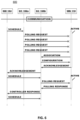
- FIG. 5 depicts a sequence diagram 500 showing polling request retransmission, in accordance with one or more embodiments of the present disclosure.
- FIG. 6 depicts a sequence diagram 600 showing wireless node re-association, in accordance with one or more embodiments of the present disclosure.
- a letter following a reference numeral is intended to reference an embodiment of the feature or element that may be similar, but not necessarily identical, to a previously described element or feature bearing the same reference numeral (e.g., 1 , 1 a , 1 b ).
- Such shorthand notations are used for purposes of convenience only and should not be construed to limit the disclosure in any way unless expressly stated to the contrary.
- any reference to “one embodiment” or “some embodiments” means that a particular element, feature, structure, or characteristic described in connection with the embodiment is included in at least one embodiment disclosed herein.
- the appearances of the phrase “in some embodiments” in various places in the specification are not necessarily all referring to the same embodiment, and embodiments may include one or more of the features expressly described or inherently present herein, or any combination or sub-combination of two or more such features, along with any other features which may not necessarily be expressly described or inherently present in the instant disclosure.
- the wireless sensor network may support applications involving battery operated wireless sensors, such as, aircraft applications. Power saving options like low duty cycle operation and nano-power timing circuits may improve a battery life of the wireless sensors.
- the timing circuit is an analog circuit.
- the timing circuit may include a provision for configuring duty cycle settings. Time synchronization is provided to achieve reliable communication in the wireless sensor network. Variable time drift in the nano-power timing circuit is accounted for to improve the time synchronization in such low data rate and duty cycle operations.
- Time synchronization may occur through exchange of configuration data among the network elements during a configuration phase and data polling and adaptive message scheduling in a communication phase. Such time synchronization may improve a communication reliability in the wireless sensor networks. Clock synchronization and group-based time slot management. Methods for time synchronization may be adaptive to dynamic changes in the network configuration of a network scale and wireless node data rate. By adapting the polling requests, a reduction in radio frequency emissions and channel congestion may be provided. Such reduction in congestion may support scalability of the network for additional wireless nodes. Algorithms are also described to time re-synchronize network elements that lose synchronization during longer operation. Thus, the wireless sensor network may support low data rate, low duty cycle operation of wireless nodes with nano-powered timers.
- FIG. 1 an architecture 100 for wireless avionics networks is described, in accordance with one or more embodiments of the present disclosure.
- An Architecture for Wireless Avionics Communication Network is described in U.S. Pat. No. 10,666,498, which is incorporated herein by reference in the entirety.
- the architecture provided therein may include a fault-tolerant design with a hierarchical topology.
- the architecture 100 may include several aircraft applications 102 .
- the aircraft applications 102 can include applications such as Integrated Vehicle Health Management (IVHM), Engine Health Management (EHM), System Health Management (SHM), Prognostics and Health Management (PHM), data loggers, or others.
- IVHM Integrated Vehicle Health Management
- EHM Engine Health Management
- SHM System Health Management
- PLM Prognostics and Health Management
- a network manager 104 is configured to communicate with external applications such as the aircraft applications 102 and a network 106 .
- the network manager 104 may be configured for bi-directional communication 103 with the data controllers 108 a - 108 n over a wired connection or wireless connection.
- a second layer includes one or more data controllers 108 a - 108 n .
- the data controllers 108 may be configured for bi-directional communication with the network manager 104 .
- the data controllers 108 may also be configured for bi-directional communication with wireless nodes 110 by a wireless connection.
- the data controllers 108 are capable of synchronous and asynchronous communication.
- the data controllers 108 are capable of aggregating/consolidating the data received from the wireless nodes 110 and transmitting the aggregated data to the network manager 104 .
- the data controllers 108 may also be configured with receive queues/buffers to buffer data that is received at various data rates.
- a third layer of the architecture 100 includes one or more wireless nodes such as wireless nodes 110 .
- the wireless nodes 110 are configured for bi-directional communication with the data controllers 108 by a transceiver of the wireless node 110 .
- the wireless nodes 110 are configured to transmit and receive data at different rates and priorities.
- the wireless nodes 110 can be grouped into different clusters 112 that are associated with respective wireless data controllers 108 by various techniques.
- the wireless nodes 110 may include devices such as but not limited to wireless sensor nodes, wireless actuator nodes, and the like.
- the wireless nodes 110 may communicate with the data controllers 108 over wireless channels of communication on a specified bandwidth.
- the wireless nodes 110 may be battery powered. Such battery power may be advantageous where the wireless nodes 110 are located in a location which not easily accessible, such as, an exterior sensor on an aircraft hull.
- the data controller 108 forms the sensor cluster 112 and manages a finite set of wireless nodes 110 in that sensor cluster 112 .
- An aircraft may provide the power to network manager 104 and data controller 108 .
- the wireless nodes 110 may be battery powered.
- the wired connection may include any wireline communication protocol (e.g., DSL-based interconnection, cable-based interconnection, T9-based interconnection, and the like) known in the art.
- the wireless connections may include any communication protocol (e.g., GSM, GPRS, CDMA, EV-DO, EDGE, WiMAX, 3G, 4G, 4G LTE, 5G, Wi-Fi protocols, RF, Bluetooth, and the like) known in the art.
- the network manager 104 may establish the network 106 and wait for the incoming data controller 108 connections.
- the data controller 108 connects to the network manager 104 when the data controller 108 discovers the network manager 104 in the network 106 .
- the data controller 108 then receives a configuration message from the network manager 104 .
- the wireless node 110 may attempt to associate to the data controller 108 referring to a preconfigured data controller 108 coordinators list.
- the wireless node 110 associates to the data controller 108 if available and receives the configuration message which includes a duty cycle configuration.
- the wireless nodes 110 may include a duty cycle.
- the duty cycle may include an active state. During the active state various components of the wireless node may be powered for full operational capability. Such components may include, but are not limited to, the timing circuit, the sensor, and/or the transceiver.
- the duty cycle may also include a low-power state. During the low-power state a transceiver and a sensor of the wireless node may be unpowered, such that, a power consumption of a battery of the wireless node 110 may be reduced.
- the duty cycle of the wireless nodes 110 may be relatively low (on the order of once per minute, or once per several minutes), such that the wireless nodes 110 may be in the low-power state for a sleep duration sleep and an active state for a wake duration.
- the wireless nodes 110 may wait for incoming polling requests. Upon receiving the polling requests, the wireless nodes 110 may send a data sample and then transition to sleep. The wireless nodes 110 may transition to sleep as per a fixed or a variable wake cycle configuration.
- the duty cycle may be based on a timing circuit of the wireless node 110 .
- the duration of the active state may be based on the wake duration of the timing circuit.
- the duration of the low-power state may be based on the sleep duration of the timing circuit.
- the sleep duration and the wake duration may be configurable. Such configuration may be provided by the configuration message from the data controller 108 .
- the timing circuit may be configured according to the sleep duration and the wake duration during an initial association of the wireless node 110 with the network 106 or during a reassociation of the wireless node 110 .
- the timing circuit may not include a memory to store an absolute time. Instead, the duty cycle may be set by passive components of the timing circuit, such as, resistors, capacitors, inductors, and one or more switches of the timing circuit. By the switches, the duty cycle of the wireless node 110 may be configured initially during the association.
- the timing circuit of the wireless nodes 110 includes a nano-power timing circuit. In this regard, during the low-power state, the nano-power timing circuit uses less than one-thousand nanowatts of power during the low-power state. This may be advantageous for prolonging the battery life of the wireless node 110 .
- the timing circuit may include a clock drift. Over time, the clock drift may accumulate such that the wireless node 110 becomes desynchronized with a reference clock, such as, but not limited to, a reference clock of the network manager 104 or the data controller 108 .
- the network manager 104 may accommodate for the clock drift of the timing circuit by adaptive scheduling of polling requests for the data controller 108 to transmit to the wireless node 110 .
- the network manager 104 may be provided with information about the sleep duration and wake duration of the wireless nodes 110 . This information may allow the network manager 104 to schedule the synchronized data polling request message. This coordination may be performed at the first association and during subsequent polling requests.
- the sequence diagram 200 may illustrate a method of time synchronization between network elements in an energy sensitive wireless sensor network.
- the network elements may be time synchronized by sharing configuration parameters.
- the configuration parameters may be shared between the network manager 104 , the data controller 108 , and the wireless node 110 .
- the configuration messages may be exchanged among the network elements during an initialization phase.
- the configuration parameters may include duty cycle information.
- polling data and adaptive message scheduling may be exchanged among the network elements during a communication phase.
- Adaptive message scheduling may be performed by the network manager 104 to maintain time synchronization between the network elements.
- the network manager 104 may perform adaptive scheduling of polling requests sent from the data controller 108 to the wireless node 110 .
- the adaptive scheduling of the data polling requests may be based on the duty cycle together with a previous response time from the wireless node 110 .
- the schedule may also be based on a tolerance of the wireless node 110 timing circuit.
- the network manager 104 may synchronize the network elements, schedule the polling messages to align with wireless node 110 active states and handle out-of-sync network elements. Details of these algorithms are explained further herein.
- a configuration message 202 may be sent from the network manager 104 to the data controller 108 .
- the configuration message 202 may include configuration parameters, such as, but not limited to, a wireless node identification (ID), a cluster size, a sleep duration, or a wake duration, or a fixed/variable wake cycle.
- the wireless node identification may provide for authentication of the wireless nodes 110 for joining the cluster 112 of the data controller 108 .
- the cluster size may limit the number of wireless nodes 110 eligible for joining the cluster 112 of the data controller 108 .
- the sleep duration may be a sleep duration for one or more wireless nodes 110 of the cluster 112 .
- the sleep duration may be used in message scheduling by the network manager 104 and for sleep operations by the wireless node 110 .
- the wake duration may be a wake duration for one or more wireless nodes 110 of the cluster 112 .
- the wake duration may be used in message scheduling by the network manager 104 and for wake operations by the wireless node 110 .
- the fixed/variable wake cycle may be used in message scheduling by the network manager 104 .
- the data controller 108 may receive the configuration message 202 and configure the cluster 112 based on one or more of the configuration parameters (e.g., the cluster size). The data controller 108 may then wait for incoming association requests from the wireless nodes 110 .
- the configuration parameters e.g., the cluster size
- the wireless node 110 may perform a scan and send an association request 203 to the data controller 108 .
- the association request 203 may include, but is not limited to, an identification of the wireless node 110 .
- the association request 203 is depicted as being sent from the wireless node 110 to the data controller 108 after the data controller 108 receives the configuration message 202 , this is not intended to be limiting.
- the wireless node 110 sends the association request 203 to the data controller 108 and then the data controller 108 receives the configuration message 202 .
- the data controller 108 may be unable to authenticate the wireless node 110 until after receiving both the configuration message 202 , including the wireless node identification, and the association request 203 .
- the data controller 108 may receive the association request 203 and compare the association request 203 with the wireless node identifications in the cluster 112 . Based on the comparison, the data controller 108 may send an association response to the wireless node 110 . Upon determining the wireless node 110 is not authenticated to join the cluster 112 , the association response sent from the data controller 108 to the wireless node 110 may include a rejection message (not depicted). Upon determining the wireless node 110 is authenticated to join the cluster 112 , the association response sent from the data controller 108 to the wireless node 110 may include a configuration message 204 .
- the configuration message 204 may include configuration parameters, such as, but not limited to, the sleep duration, the wake duration, or the fixed/variable wake cycle.
- the wireless node 110 may receive the configuration message 204 and configure one or more components based on one or more of the configuration parameters.
- the wireless node 110 may configure the timing circuit based on the sleep duration and the wake duration.
- a power consumption of the wireless node 110 may be reduced, such that the transceiver and the sensor are unpowered.
- the wireless node 110 may be configured with a sleep duration between fifteen and thirty minutes.
- the transceiver and the sensor may be powered, such that the wireless node may receive data polling requests by the transceiver and generate sensor data by the sensor.
- the duty cycle of the wireless node 110 may be configured based on the configuration message 204 .
- the timing circuit may be configured based on the fixed wake cycle or the variable wake cycle. Where the timing circuit is configured with the variable wake cycle, the wireless node 110 may transmit a data sample immediately upon receiving a data polling request and generating a sensor measurement. Where the timing circuit is configured with the fixed wake cycle, the wireless node 110 may transmit the data sample after receiving the data polling request, generating the sensor measurement, and waiting until the end of the wake duration.
- the wireless node 110 may transmit an acknowledgement message 206 to the data controller 108 .
- the acknowledgement message 206 may include a confirmation that the wireless node 110 is configured according to the configuration parameters.
- the wireless data controller 108 may receive the acknowledgement message 206 from the data controller 108 at an acknowledgement receipt time.
- the node 110 may remain in an active state until after a first polling request 212 is received and a polling response 214 is transmitted (as depicted).
- the node 110 may begin the low-power portion of the duty cycle immediately after sending the acknowledgement message 206 (not depicted).
- the data controller 108 may then transmit an acknowledgement message 208 to the network manager 104 .
- the acknowledgement message 208 may include a list of wireless nodes 110 in the cluster 112 of the data controller 108 , and a confirmation that the wireless nodes 110 are configured according to the various configuration parameters. Adaptive message scheduling will then be handled in a communication phase.
- the network manager 104 may receive the acknowledgement message 208 and initiate a scheduling algorithm.
- the network manager 104 may schedule a first series of data polling request messages to the wireless nodes 110 after receiving the acknowledgement for the configuration message.
- the scheduling algorithm may determine a polling request schedule 210 .
- the polling request schedule 210 may be a time at which a series of polling requests may be sent from the data controller 108 to the wireless node 110 .
- the polling request schedule 210 may be determined based on a sleep duration of the wireless node, a tolerance of the timing circuit, and a receipt time of a previous polling response.
- Reducing the number of polling requests sent by the data controller 108 may similarly reducing a channel congestion.
- the reduced channel congestion may increase a number of available wireless nodes able to communicate with the data controller 108 by the channel.
- the network manager 104 may transmit the first polling request schedule 210 to the data controller 108 .
- the data controller 108 may receive the polling request schedule 210 from the network manager 104 .
- the data controller 108 may then transmit polling requests 212 to the wireless node 110 according to the polling request schedule 210 .
- the wireless node 110 may receive one of the data polling request messages, send a polling response including sensor data, and enters a low-power state.
- the data controller 108 may receive the polling response and generate a receipt time at which the polling response is received by the data controller 108 .
- the time may be determined by one or more clocks of the data controller 108 .
- the clock of the data controller 108 is synchronized with a master clock of the network manager 104 .
- the data controller 108 may then transmit a controller response 216 to the network manager 104 , the controller response 216 including the polling response 214 and the receipt time.
- the network manager 104 may receive the controller response 216 . Such controller response 216 may be used by the network manager 104 for coordinating a subsequent polling request schedule.
- the network manager 104 may consider the receipt time as the start of the low-power state wireless node 110 .
- the network manager 104 then schedules the second series of data polling request messages prior to the start of the active state of the wireless node.
- the schedule may be based on the sleep duration of the wireless node 110 , a tolerance of the wireless node timing circuit, and the receipt time.
- the sensor data may be provided to various aircraft applications 102 .
- a second batch of polling requests may then be sent from the data controller 108 to the wireless node 110 , according to the second polling request schedule.
- FIG. 2 depicts a second batch of polling request 212 a , polling request 212 b , and polling request 212 c .
- the polling requests 212 a and polling request 212 b are not received by the wireless node 110 .
- the polling request 212 a and polling request 212 b are not received by the wireless node 110 because the wireless node 110 is in the sleep duration such that the transceiver of the wireless node 110 is not currently in an active state.
- the network manager 104 may have scheduled the polling requests 212 a and polling request 212 b during the low-power state, because an actual time drift associated with the timing circuit of the wireless node 110 is unknown by the network manager 104 .
- the wireless node 110 transitions into a second active state after the sleep duration and waits to receive one of the second batch of data polling request.
- the polling request 212 c may be received by the wireless node 110 (i.e., by way of the transceiver during the wake duration).
- the wireless node 110 may generate sensor data by the sensor.
- the wireless node 110 may then transmit a polling response 214 including the sensor data to the data controller 108 by way of the transceiver. Subsequent to transmitting the polling response 214 , the wireless node 110 may be put into sleep mode.
- the wireless node 110 may transmit the polling response 214 at the end of the wake duration or prior to the end of the wake duration. Where the timing circuit is configured with the variable wake cycle, the wireless node 110 may transmit the polling response 214 immediately upon measurement by the sensor. In this regard, the wireless node 110 may be put into sleep mode before the wake duration has expired. This may be advantageous in reducing a power consumption of the wireless node 110 .
- the data polling request and response sequence is then continued for a desired number of duty cycles of the wireless node 110 .
- the network manager 104 may adapt and generate the polling request schedules for any number (N) of duty cycles. In some embodiments, the duty cycles may continue throughout a flight of an aircraft.
- FIG. 2 depicts a wireless node 110 and a data controller 108 , this is not intended as a limitation on the present disclosure.
- FIG. 1 depicts the network 106 with a plurality of data controllers 108 , with each data controller 108 including a cluster 112 with a plurality of wireless nodes 110 .
- the network manager 104 may generate the polling request schedule 210 for such network 106 .
- sequence diagrams 300 a and 300 b are described, in accordance with one or more embodiments of the present disclosure.
- the sequence diagrams 300 a and 300 b may depict one or more methods of accounting for timing drift by an algorithm.
- the algorithm of the network manager 104 for determining the schedule of polling requests may consider variations in the time behavior of the wireless node 110 , thereby accounting for timer drifts in the wake duration or the sleep duration.
- the wireless node 110 may include a turnaround time.
- the turnaround time may indicate a time between a polling request which is received by the wireless node 110 to a response at the data controller.
- the turnaround time is a fixed turnaround time.
- the fixed turnaround time may be determined empirically based on the type of the wireless node. Such fixed turnaround time may be stored in a configuration file of the network manager 104 .
- the turnaround time is a variable turnaround time.
- the variable turnaround time may be based on timer drift analysis for previous turnaround times between the data controller 108 and the wireless node. For example, FIGS. 3 A- 3 B depict the node turnaround time based on the immediately previous (i ⁇ 1) node turnaround time (e.g., T.
- variable node turnaround time may be similarly based on multiple historical turnaround times between the data controller 108 and the wireless node 110 . In some embodiments, the variable turnaround time is adapted from the fixed turnaround time.
- the timing circuit of the wireless node 110 may include a tolerance (T.BUF).
- the tolerance may be based on statistics of the error associated with the timing circuit.
- the network manager 104 may schedule a series of polling request messages R1 to RN.
- the polling requests may be scheduled such that a time window between any two polling requests is at least equal to the turnaround time.
- the wireless node 110 will have sufficient time to respond to the previous polling request before the next polling request is sent.
- scheduling the polling requests within this time window may reduce channel congestion.
- the time window may be less than or equal to half of the wake duration. Providing polling requests at a higher rate than wireless node's wake duration may allow the wireless node 110 to receive the polling request without the awake state of the wireless node falling between sequential polling requests. For example, FIGS.
- the schedule for the current duty cycle (i) may include a series of request R1 to RN based on the previous time at which the polling response from the wireless node 110 is received (T.RECEIPT).
- a first polling request R1(i) for the current duty cycle (i) starts at a time T.R1(i).
- the time T.R1(i) of the first polling request may be based on the receipt time of the previous polling response, the sleep duration of the timing circuit, and the tolerance of the timing circuit.
- the timing circuit is configured with a fixed wake cycle. Where the timing circuit is configured with a fixed wake cycle, the timing circuit may include a remaining wake duration T.REMAIN after transmitting the polling response. The remaining wake duration may be transmitted with the polling response.
- the network manager 104 may account for the remaining wake duration, such that the time of the first polling request for the current duty cycle (i) may also be based on the wake duration.
- a final polling request RN(i) for the current duty cycle (i) may be based on the receipt time of the previous polling response, the sleep duration of the timing circuit, and the tolerance of the timing circuit.
- the timing circuit is configured with a fixed wake cycle. Where the timing circuit is configured with a fixed wake cycle, the timing circuit may include the remaining wake duration (e.g., T.REMAIN) after transmitting the polling response.
- the network manager 104 may account for the remaining wake duration, such that the time of the final polling request for the current duty cycle (i) may also be based on the wake duration.
- the network manager 104 may schedule polling requests for multiple data controllers 108 , multiple nodes 110 , or multiple clusters 112 . Polling request scheduling for each wireless node 110 is handled based on respective wake durations of the wireless nodes 110 .
- the sequence diagram 400 may illustrate a method of scheduling for multiple wireless nodes.
- the cluster 112 may include multiple wireless nodes 110 .
- Each wireless node 110 may include a wake duration.
- the network manager 104 may schedule the data polling requests for each of such wireless nodes 110 .
- the active states of the wireless nodes 110 may at least partially overlap.
- a sequential scheduling method may be used to sequence the requests. For example, a wireless node 110 a and a wireless node 110 b may wake up at a similar time, such that the active state of the wireless node 110 a and the active state of the wireless node 110 b may at least partially overlap.
- the network manager 104 may generate the polling request schedule such that the polling requests from the data controller 108 do not overlap in a transmission channel.
- the polling request transmitted to the wireless node 110 a and the polling requests transmitted to the wireless node 110 b may be sequential. Such sequential transmission may be advantageous such that each wireless node 110 may receive polling requests during the active state.
- the sequence diagram 500 may illustrate a method of wireless node re-synchronization.
- Wireless nodes 110 may lose synchronization with the network manager 104 .
- the wireless nodes 110 may lose synchronization for various reasons, such as, during longer operations, by delays in the wireless node 110 , or a momentary reset of the wireless node 110 .
- the data controller 108 does not receive the polling response in response to the polling requests.
- additional polling requests may be retransmitted to the wireless node 110 .
- the additional polling requests may be transmitted with an interval similar to that set forth in the schedule from the network manager.
- the wireless node 110 may receive a polling request of the additional polling requests and transmit the sensor data.
- the controller response including the polling response together with a receipt time may then be transmitted to the network manager 104 .
- the network manager may then generate a subsequent polling request schedule for the wireless node 110 based on the time of receipt of the sensor data, per the adaptive message scheduling previously described herein.
- the data controller 108 may resynchronize with the wireless node 110 , at the cost of taking up the wireless channel.
- polling request scheduling may be stopped for that wireless node 110 .
- the polling request scheduling may be stopped until the wireless node is re-associated with a data controller of the network 106 .
- a timeout may occur at the network manager 104 or the data controller 108 .
- Various scenarios may require the data controller 108 or the network manager 104 to re-associate the wireless nodes 110 .
- Such scenarios may include, but are not limited to, power loss at the network manager 104 , power loss at the data controller 108 , reset of the network manager 104 , or reset of the data controller 108 .
- the data controller 108 may re-establish either the cluster 112 or the network manager 104 may re-establish the network 106 . In these cases, data requests will not be received from the network manager 104 to the wireless nodes 110 .
- the wireless node 110 may be currently associated with the data controller 108 a . If the wireless node 110 does not receive any data request from the data controller 108 a during the wake duration (e.g., TON), the wireless node 110 may attempt to associate with a next available data controller, such as the data controller 108 b . The wireless node 110 may transmit the association request to the data controller 108 b . The data controller 108 b may authenticate the wireless node 110 based on the association request and a wireless node identification portion of a configuration message received from the network manager 104 . Upon successful authentication, the data controller 108 b may transmit the configuration message to the wireless node 110 and await an acknowledgement.
- TON wake duration
- Adaptive message scheduling, polling requests, and sensor data communication may then commence. As depicted in FIG. 6 , the wireless node 110 may remain in the active state past the wake duration for reassociation purposes. Alternatively, the wireless node 110 may reassociate during the next active state. However, remaining in the active state past the wake duration may be advantageous in more rapidly reassociating the wireless node 110 and similarly receiving the sensor data.
- the herein described methods may improve a communication reliability of wireless sensor networks with battery powered elements through time synchronization and adaptive message scheduling.
- the methods may support low data rate, low duty cycle operations of energy conservative wireless nodes with nano-powered timers.
- the time synchronization may be initialized by configuring a duty cycle of the wireless nodes.
- a reduction of radio frequency emissions from data controllers may occur through a selection of optimal time windows and data polling rates, thereby reducing channel congestion.
- the wireless sensor network may be scaled to include a greater number of wireless nodes.
- IHM Integrated vehicle health management
- PLM Prognostics and Health Management
- SHM System Health Management
- AHM Airplane Health Management
- EHM Engine Health Management
- example embodiments of the present disclosure are shown and described in an aircraft environment, the inventive concepts of the present disclosure may be configured to operate in any wireless networking known in the art.
- embodiments may be described throughout the present disclosure in an aircraft environment. However, these references are not to be regarded as limiting. Thus, references to “aircraft” or “aviation,” and like terms should not be interpreted as a limitation on the present disclosure, unless noted otherwise herein.
- any two components herein combined to achieve a particular functionality can be seen as “associated with” each other such that the desired functionality is achieved, irrespective of architectures or intermedial components.
- any two components so associated can also be viewed as being “connected,” or “coupled,” to each other to achieve the desired functionality, and any two components capable of being so associated can also be viewed as being “couplable,” to each other to achieve the desired functionality.
- Specific examples of couplable include but are not limited to wirelessly interactable and/or wirelessly interacting components and/or logically interacting and/or logically interactable components.
- One or more components of the architecture 100 may include a processor, such as, but not limited to, the network manager 104 .
- a processor such as, but not limited to, the network manager 104 .
- the term “processor” or “processing element” may be broadly defined to encompass any device having one or more processing or logic elements (e.g., one or more micro-processor devices, one or more application specific integrated circuit (ASIC) devices, one or more field programmable gate arrays (FPGAs), or one or more digital signal processors (DSPs)).
- the one or more processors may include any device configured to execute algorithms and/or instructions (e.g., program instructions stored in memory).
- the processor may be configured to execute a set of program instruction maintained on a memory medium.
- the memory may include any storage medium known in the art suitable for storing program instructions executable by the associated processor.
- the memory medium may include a non-transitory memory medium.
- the memory medium may include, but is not limited to, a read-only memory (ROM), a random-access memory (RAM), a magnetic or optical memory device (e.g., disk), a solid-state drive and the like.
- ROM read-only memory
- RAM random-access memory
- magnetic or optical memory device e.g., disk
- solid-state drive solid-state drive and the like.
- memory medium may be housed in a common controller housing with the processor.
- the memory medium may be located remotely with respect to the physical location of the one processor.
- the processor may execute any of the various process steps described throughout the present disclosure, such as, but not limited to adaptive scheduling of polling requests.
- the methods described herein may include storing results of one or more steps of the method embodiments in memory.
- the results may include any of the results described herein and may be stored in any manner known in the art.
- the memory may include any memory described herein or any other suitable storage medium known in the art.
- the results can be accessed in the memory and used by any of the method or system embodiments described herein, formatted for display to a user, used by another software module, method, or system, and the like.
- the results may be stored “permanently,” “semi-permanently,” temporarily,” or for some period of time.
- the memory may be random access memory (RAM), and the results may not necessarily persist indefinitely in the memory.
- each of the embodiments of the method described above may include any other step(s) of any other method(s) described herein.
- each of the embodiments of the method described above may be performed by any of the systems described herein. It is to be noted that the specific order of steps in the foregoing disclosed methods are examples of exemplary approaches. Based upon design preferences, it is understood that the specific order of steps in the method can be rearranged while remaining within the scope of the present disclosure.
Landscapes
- Engineering & Computer Science (AREA)
- Computer Networks & Wireless Communication (AREA)
- Signal Processing (AREA)
- Computer Security & Cryptography (AREA)
- Mobile Radio Communication Systems (AREA)
Abstract
Description
Claims (19)
Priority Applications (1)
| Application Number | Priority Date | Filing Date | Title |
|---|---|---|---|
| EP22156625.0A EP4125295B1 (en) | 2021-07-27 | 2022-02-14 | Time synchronization in wireless networks |
Applications Claiming Priority (2)
| Application Number | Priority Date | Filing Date | Title |
|---|---|---|---|
| IN202141033728 | 2021-07-27 | ||
| IN202141033728 | 2021-07-27 |
Publications (2)
| Publication Number | Publication Date |
|---|---|
| US20230032215A1 US20230032215A1 (en) | 2023-02-02 |
| US12120608B2 true US12120608B2 (en) | 2024-10-15 |
Family
ID=85038239
Family Applications (1)
| Application Number | Title | Priority Date | Filing Date |
|---|---|---|---|
| US17/474,814 Active 2043-03-11 US12120608B2 (en) | 2021-07-27 | 2021-09-14 | Time synchronization in wireless networks |
Country Status (1)
| Country | Link |
|---|---|
| US (1) | US12120608B2 (en) |
Families Citing this family (1)
| Publication number | Priority date | Publication date | Assignee | Title |
|---|---|---|---|---|
| FI20216285A1 (en) * | 2021-12-16 | 2023-06-17 | Nokia Solutions & Networks Oy | Predicting Clock Drifting |
Citations (15)
| Publication number | Priority date | Publication date | Assignee | Title |
|---|---|---|---|---|
| US20070171859A1 (en) * | 2006-01-20 | 2007-07-26 | Cisco Technology Inc. | Intelligent Association of Nodes with PAN Coordinator |
| US20090207769A1 (en) | 2008-01-14 | 2009-08-20 | Electronics And Telecommunications Research Institute | Method and apparatus for scheduling timing for communication between sensor nodes in wireless sensor network |
| US7688802B2 (en) | 2008-05-23 | 2010-03-30 | Honeywell International Inc. | System and method for time synchronization in a wireless network |
| US7817616B2 (en) | 2006-01-09 | 2010-10-19 | Samsung Electronics Co., Ltd. | Time synchronization method in wireless sensor network |
| US7826818B2 (en) | 1991-05-13 | 2010-11-02 | Broadcom Corporation | Network supporting roaming, sleeping terminals |
| US20110002251A1 (en) | 2007-07-12 | 2011-01-06 | Shin Chang Sub | Time synchronization and routing method in wireless sensor network, and apparatus for enabling the method |
| US8478314B2 (en) | 2009-07-06 | 2013-07-02 | Gangneung-Wonju National University Industry Academy Cooperation Group | Communication method for a mobile sensor node in a wireless sensor network |
| US9119185B2 (en) | 2013-03-29 | 2015-08-25 | Olympus Corporation | Power-saving hub messages in wireless body area networks |
| US20160037449A1 (en) | 2014-07-31 | 2016-02-04 | Texas Instruments Incorporated | Slot Skipping Techniques for Reduced Power Consumption in Time Slotted Channel Hopping MAC Protocol |
| US20160088557A1 (en) | 2013-05-07 | 2016-03-24 | University Of Ulsan Foundation For Industry Cooperation | Time synchronization method for energy-efficient in wireless network and network adopting same |
| US20160182432A1 (en) | 2014-12-17 | 2016-06-23 | Google Inc. | Wireless network reliabilty over relatively low-power protocols |
| US20190334760A1 (en) | 2018-04-26 | 2019-10-31 | Rosemount Aerospace Inc. | Architecture for wireless avionics communication networks |
| US20200275373A1 (en) * | 2017-05-08 | 2020-08-27 | Electronics And Telecommunications Research Institute | Operation method of communication node for supporting low power mode in wireless lan |
| US20200305229A1 (en) * | 2017-12-21 | 2020-09-24 | Huawei Technologies Co., Ltd. | Wireless sensor management method, and wireless communication system |
| US10848302B2 (en) * | 2018-04-12 | 2020-11-24 | Simmonds Precision Products, Inc. | Network security framework for wireless aircraft communication |
-
2021
- 2021-09-14 US US17/474,814 patent/US12120608B2/en active Active
Patent Citations (16)
| Publication number | Priority date | Publication date | Assignee | Title |
|---|---|---|---|---|
| US7826818B2 (en) | 1991-05-13 | 2010-11-02 | Broadcom Corporation | Network supporting roaming, sleeping terminals |
| US7817616B2 (en) | 2006-01-09 | 2010-10-19 | Samsung Electronics Co., Ltd. | Time synchronization method in wireless sensor network |
| US20070171859A1 (en) * | 2006-01-20 | 2007-07-26 | Cisco Technology Inc. | Intelligent Association of Nodes with PAN Coordinator |
| US20110002251A1 (en) | 2007-07-12 | 2011-01-06 | Shin Chang Sub | Time synchronization and routing method in wireless sensor network, and apparatus for enabling the method |
| US20090207769A1 (en) | 2008-01-14 | 2009-08-20 | Electronics And Telecommunications Research Institute | Method and apparatus for scheduling timing for communication between sensor nodes in wireless sensor network |
| US7688802B2 (en) | 2008-05-23 | 2010-03-30 | Honeywell International Inc. | System and method for time synchronization in a wireless network |
| US8478314B2 (en) | 2009-07-06 | 2013-07-02 | Gangneung-Wonju National University Industry Academy Cooperation Group | Communication method for a mobile sensor node in a wireless sensor network |
| US9119185B2 (en) | 2013-03-29 | 2015-08-25 | Olympus Corporation | Power-saving hub messages in wireless body area networks |
| US20160088557A1 (en) | 2013-05-07 | 2016-03-24 | University Of Ulsan Foundation For Industry Cooperation | Time synchronization method for energy-efficient in wireless network and network adopting same |
| US20160037449A1 (en) | 2014-07-31 | 2016-02-04 | Texas Instruments Incorporated | Slot Skipping Techniques for Reduced Power Consumption in Time Slotted Channel Hopping MAC Protocol |
| US20160182432A1 (en) | 2014-12-17 | 2016-06-23 | Google Inc. | Wireless network reliabilty over relatively low-power protocols |
| US20200275373A1 (en) * | 2017-05-08 | 2020-08-27 | Electronics And Telecommunications Research Institute | Operation method of communication node for supporting low power mode in wireless lan |
| US20200305229A1 (en) * | 2017-12-21 | 2020-09-24 | Huawei Technologies Co., Ltd. | Wireless sensor management method, and wireless communication system |
| US10848302B2 (en) * | 2018-04-12 | 2020-11-24 | Simmonds Precision Products, Inc. | Network security framework for wireless aircraft communication |
| US20190334760A1 (en) | 2018-04-26 | 2019-10-31 | Rosemount Aerospace Inc. | Architecture for wireless avionics communication networks |
| US10666498B2 (en) | 2018-04-26 | 2020-05-26 | Rosemount Aerospace Inc. | Architecture for wireless avionics communication networks |
Non-Patent Citations (1)
| Title |
|---|
| Extended Search Report in European Application No. 22156625.0 dated Oct. 14, 2022, 13 pages. |
Also Published As
| Publication number | Publication date |
|---|---|
| US20230032215A1 (en) | 2023-02-02 |
Similar Documents
| Publication | Publication Date | Title |
|---|---|---|
| US11656671B2 (en) | Negotiating a transmit wake time | |
| EP2479925B1 (en) | Dynamic power management in a communications device | |
| JP7066757B2 (en) | Communication device and communication method | |
| US7693117B2 (en) | Power-saving mechanism for periodic traffic streams in wireless local-area networks | |
| US8295217B2 (en) | Method and apparatus for a device power savings class | |
| EP2106192A2 (en) | Communication apparatus and communication method, and computer program therefor | |
| US20160112947A1 (en) | Method and apparatus to improve wireless device performance | |
| KR102060943B1 (en) | Communication device, communication method and communication program stored in the storage medium | |
| CN111226467A (en) | Communication device and communication method | |
| US20170310358A1 (en) | Sleepy device operation in asynchronous channel hopping networks | |
| US12108342B2 (en) | Technique for skip signal transmission | |
| CN107820277B (en) | Parent node device for wireless network, terminal device and data transmission method thereof | |
| US12120608B2 (en) | Time synchronization in wireless networks | |
| WO2024164971A1 (en) | Communication method and apparatus | |
| US20230068824A1 (en) | Resume and suspend periodic service | |
| EP4125295B1 (en) | Time synchronization in wireless networks | |
| WO2022083418A1 (en) | Energy saving signal transmission method and apparatus | |
| CN104025667B (en) | Systems and methods for scheduling communications | |
| WO2008103863A1 (en) | Mesh network control using common designation wake-up | |
| Hwang et al. | Ultra Low Power Data Aggregation for Request Oriented Sensor Networks. | |
| Facchinetti et al. | Wireless real-time communication protocol for cooperating mobile units | |
| JP2024121958A (en) | Wireless communication device, wireless communication program, and wireless communication method | |
| CN119172421A (en) | Vehicle communication method, vehicle and computer program product | |
| CN118283853A (en) | Sidelink communication method, communication device and communication system |
Legal Events
| Date | Code | Title | Description |
|---|---|---|---|
| AS | Assignment |
Owner name: GOODRICH AEROSPACE SERVICES PRIVATE LIMITED, INDIA Free format text: ASSIGNMENT OF ASSIGNORS INTEREST;ASSIGNORS:PRASANNA, RAMAMURTHY;THUPAKULA, KIRAN;SHRESHTHI, MAHADEVANNA;REEL/FRAME:057479/0231 Effective date: 20210914 |
|
| FEPP | Fee payment procedure |
Free format text: ENTITY STATUS SET TO UNDISCOUNTED (ORIGINAL EVENT CODE: BIG.); ENTITY STATUS OF PATENT OWNER: LARGE ENTITY |
|
| STPP | Information on status: patent application and granting procedure in general |
Free format text: DOCKETED NEW CASE - READY FOR EXAMINATION |
|
| AS | Assignment |
Owner name: ROCKWELL COLLINS, INC., IOWA Free format text: ASSIGNMENT OF ASSIGNORS INTEREST;ASSIGNOR:GOODRICH AEROSPACE SERVICES PRIVATE LIMITED;REEL/FRAME:058738/0863 Effective date: 20211209 |
|
| AS | Assignment |
Owner name: ARINC INCORPORATED, MARYLAND Free format text: ASSIGNMENT OF ASSIGNORS INTEREST;ASSIGNOR:ROCKWELL COLLINS, INC.;REEL/FRAME:063539/0290 Effective date: 20230503 |
|
| STPP | Information on status: patent application and granting procedure in general |
Free format text: NON FINAL ACTION MAILED |
|
| STPP | Information on status: patent application and granting procedure in general |
Free format text: NOTICE OF ALLOWANCE MAILED -- APPLICATION RECEIVED IN OFFICE OF PUBLICATIONS |
|
| ZAAB | Notice of allowance mailed |
Free format text: ORIGINAL CODE: MN/=. |
|
| STPP | Information on status: patent application and granting procedure in general |
Free format text: PUBLICATIONS -- ISSUE FEE PAYMENT VERIFIED |
|
| STCF | Information on status: patent grant |
Free format text: PATENTED CASE |