US12102321B2 - Methods of operating a robotic surgical stapler - Google Patents
Methods of operating a robotic surgical stapler Download PDFInfo
- Publication number
- US12102321B2 US12102321B2 US17/402,674 US202117402674A US12102321B2 US 12102321 B2 US12102321 B2 US 12102321B2 US 202117402674 A US202117402674 A US 202117402674A US 12102321 B2 US12102321 B2 US 12102321B2
- Authority
- US
- United States
- Prior art keywords
- motor
- firing
- assembly
- end effector
- staple
- Prior art date
- Legal status (The legal status is an assumption and is not a legal conclusion. Google has not performed a legal analysis and makes no representation as to the accuracy of the status listed.)
- Active, expires
Links
Images


Classifications
-
- A—HUMAN NECESSITIES
- A61—MEDICAL OR VETERINARY SCIENCE; HYGIENE
- A61B—DIAGNOSIS; SURGERY; IDENTIFICATION
- A61B17/00—Surgical instruments, devices or methods
- A61B17/068—Surgical staplers, e.g. containing multiple staples or clamps
- A61B17/0682—Surgical staplers, e.g. containing multiple staples or clamps for applying U-shaped staples or clamps, e.g. without a forming anvil
- A61B17/0686—Surgical staplers, e.g. containing multiple staples or clamps for applying U-shaped staples or clamps, e.g. without a forming anvil having a forming anvil staying below the tissue during stapling
-
- A—HUMAN NECESSITIES
- A61—MEDICAL OR VETERINARY SCIENCE; HYGIENE
- A61B—DIAGNOSIS; SURGERY; IDENTIFICATION
- A61B17/00—Surgical instruments, devices or methods
- A61B17/068—Surgical staplers, e.g. containing multiple staples or clamps
- A61B17/072—Surgical staplers, e.g. containing multiple staples or clamps for applying a row of staples in a single action, e.g. the staples being applied simultaneously
- A61B17/07207—Surgical staplers, e.g. containing multiple staples or clamps for applying a row of staples in a single action, e.g. the staples being applied simultaneously the staples being applied sequentially
-
- A—HUMAN NECESSITIES
- A61—MEDICAL OR VETERINARY SCIENCE; HYGIENE
- A61B—DIAGNOSIS; SURGERY; IDENTIFICATION
- A61B17/00—Surgical instruments, devices or methods
- A61B17/068—Surgical staplers, e.g. containing multiple staples or clamps
- A61B17/072—Surgical staplers, e.g. containing multiple staples or clamps for applying a row of staples in a single action, e.g. the staples being applied simultaneously
-
- A—HUMAN NECESSITIES
- A61—MEDICAL OR VETERINARY SCIENCE; HYGIENE
- A61B—DIAGNOSIS; SURGERY; IDENTIFICATION
- A61B34/00—Computer-aided surgery; Manipulators or robots specially adapted for use in surgery
-
- A—HUMAN NECESSITIES
- A61—MEDICAL OR VETERINARY SCIENCE; HYGIENE
- A61B—DIAGNOSIS; SURGERY; IDENTIFICATION
- A61B34/00—Computer-aided surgery; Manipulators or robots specially adapted for use in surgery
- A61B34/30—Surgical robots
-
- A—HUMAN NECESSITIES
- A61—MEDICAL OR VETERINARY SCIENCE; HYGIENE
- A61B—DIAGNOSIS; SURGERY; IDENTIFICATION
- A61B17/00—Surgical instruments, devices or methods
- A61B2017/00017—Electrical control of surgical instruments
-
- A—HUMAN NECESSITIES
- A61—MEDICAL OR VETERINARY SCIENCE; HYGIENE
- A61B—DIAGNOSIS; SURGERY; IDENTIFICATION
- A61B17/00—Surgical instruments, devices or methods
- A61B2017/00017—Electrical control of surgical instruments
- A61B2017/00137—Details of operation mode
- A61B2017/00141—Details of operation mode continuous, e.g. wave
-
- A—HUMAN NECESSITIES
- A61—MEDICAL OR VETERINARY SCIENCE; HYGIENE
- A61B—DIAGNOSIS; SURGERY; IDENTIFICATION
- A61B17/00—Surgical instruments, devices or methods
- A61B2017/00017—Electrical control of surgical instruments
- A61B2017/00137—Details of operation mode
- A61B2017/00154—Details of operation mode pulsed
- A61B2017/00172—Pulse trains, bursts, intermittent continuous operation
-
- A—HUMAN NECESSITIES
- A61—MEDICAL OR VETERINARY SCIENCE; HYGIENE
- A61B—DIAGNOSIS; SURGERY; IDENTIFICATION
- A61B17/00—Surgical instruments, devices or methods
- A61B17/00234—Surgical instruments, devices or methods for minimally invasive surgery
- A61B2017/00292—Surgical instruments, devices or methods for minimally invasive surgery mounted on or guided by flexible, e.g. catheter-like, means
- A61B2017/003—Steerable
- A61B2017/00305—Constructional details of the flexible means
- A61B2017/00309—Cut-outs or slits
-
- A—HUMAN NECESSITIES
- A61—MEDICAL OR VETERINARY SCIENCE; HYGIENE
- A61B—DIAGNOSIS; SURGERY; IDENTIFICATION
- A61B17/00—Surgical instruments, devices or methods
- A61B17/00234—Surgical instruments, devices or methods for minimally invasive surgery
- A61B2017/00292—Surgical instruments, devices or methods for minimally invasive surgery mounted on or guided by flexible, e.g. catheter-like, means
- A61B2017/003—Steerable
- A61B2017/00305—Constructional details of the flexible means
- A61B2017/00314—Separate linked members
-
- A—HUMAN NECESSITIES
- A61—MEDICAL OR VETERINARY SCIENCE; HYGIENE
- A61B—DIAGNOSIS; SURGERY; IDENTIFICATION
- A61B17/00—Surgical instruments, devices or methods
- A61B2017/00367—Details of actuation of instruments, e.g. relations between pushing buttons, or the like, and activation of the tool, working tip, or the like
- A61B2017/00398—Details of actuation of instruments, e.g. relations between pushing buttons, or the like, and activation of the tool, working tip, or the like using powered actuators, e.g. stepper motors, solenoids
-
- A—HUMAN NECESSITIES
- A61—MEDICAL OR VETERINARY SCIENCE; HYGIENE
- A61B—DIAGNOSIS; SURGERY; IDENTIFICATION
- A61B17/00—Surgical instruments, devices or methods
- A61B2017/00477—Coupling
-
- A—HUMAN NECESSITIES
- A61—MEDICAL OR VETERINARY SCIENCE; HYGIENE
- A61B—DIAGNOSIS; SURGERY; IDENTIFICATION
- A61B17/00—Surgical instruments, devices or methods
- A61B17/068—Surgical staplers, e.g. containing multiple staples or clamps
- A61B17/072—Surgical staplers, e.g. containing multiple staples or clamps for applying a row of staples in a single action, e.g. the staples being applied simultaneously
- A61B2017/07214—Stapler heads
- A61B2017/07228—Arrangement of the staples
-
- A—HUMAN NECESSITIES
- A61—MEDICAL OR VETERINARY SCIENCE; HYGIENE
- A61B—DIAGNOSIS; SURGERY; IDENTIFICATION
- A61B17/00—Surgical instruments, devices or methods
- A61B17/068—Surgical staplers, e.g. containing multiple staples or clamps
- A61B17/072—Surgical staplers, e.g. containing multiple staples or clamps for applying a row of staples in a single action, e.g. the staples being applied simultaneously
- A61B2017/07214—Stapler heads
- A61B2017/07257—Stapler heads characterised by its anvil
-
- A—HUMAN NECESSITIES
- A61—MEDICAL OR VETERINARY SCIENCE; HYGIENE
- A61B—DIAGNOSIS; SURGERY; IDENTIFICATION
- A61B17/00—Surgical instruments, devices or methods
- A61B17/068—Surgical staplers, e.g. containing multiple staples or clamps
- A61B17/072—Surgical staplers, e.g. containing multiple staples or clamps for applying a row of staples in a single action, e.g. the staples being applied simultaneously
- A61B2017/07214—Stapler heads
- A61B2017/07271—Stapler heads characterised by its cartridge
-
- A—HUMAN NECESSITIES
- A61—MEDICAL OR VETERINARY SCIENCE; HYGIENE
- A61B—DIAGNOSIS; SURGERY; IDENTIFICATION
- A61B17/00—Surgical instruments, devices or methods
- A61B17/068—Surgical staplers, e.g. containing multiple staples or clamps
- A61B17/072—Surgical staplers, e.g. containing multiple staples or clamps for applying a row of staples in a single action, e.g. the staples being applied simultaneously
- A61B2017/07214—Stapler heads
- A61B2017/07278—Stapler heads characterised by its sled or its staple holder
-
- A—HUMAN NECESSITIES
- A61—MEDICAL OR VETERINARY SCIENCE; HYGIENE
- A61B—DIAGNOSIS; SURGERY; IDENTIFICATION
- A61B17/00—Surgical instruments, devices or methods
- A61B17/068—Surgical staplers, e.g. containing multiple staples or clamps
- A61B17/072—Surgical staplers, e.g. containing multiple staples or clamps for applying a row of staples in a single action, e.g. the staples being applied simultaneously
- A61B2017/07214—Stapler heads
- A61B2017/07285—Stapler heads characterised by its cutter
-
- A—HUMAN NECESSITIES
- A61—MEDICAL OR VETERINARY SCIENCE; HYGIENE
- A61B—DIAGNOSIS; SURGERY; IDENTIFICATION
- A61B34/00—Computer-aided surgery; Manipulators or robots specially adapted for use in surgery
- A61B34/20—Surgical navigation systems; Devices for tracking or guiding surgical instruments, e.g. for frameless stereotaxis
- A61B2034/2046—Tracking techniques
- A61B2034/2059—Mechanical position encoders
-
- A—HUMAN NECESSITIES
- A61—MEDICAL OR VETERINARY SCIENCE; HYGIENE
- A61B—DIAGNOSIS; SURGERY; IDENTIFICATION
- A61B90/00—Instruments, implements or accessories specially adapted for surgery or diagnosis and not covered by any of the groups A61B1/00 - A61B50/00, e.g. for luxation treatment or for protecting wound edges
- A61B90/06—Measuring instruments not otherwise provided for
- A61B2090/061—Measuring instruments not otherwise provided for for measuring dimensions, e.g. length
-
- A—HUMAN NECESSITIES
- A61—MEDICAL OR VETERINARY SCIENCE; HYGIENE
- A61B—DIAGNOSIS; SURGERY; IDENTIFICATION
- A61B90/00—Instruments, implements or accessories specially adapted for surgery or diagnosis and not covered by any of the groups A61B1/00 - A61B50/00, e.g. for luxation treatment or for protecting wound edges
- A61B90/08—Accessories or related features not otherwise provided for
- A61B2090/0803—Counting the number of times an instrument is used
-
- A—HUMAN NECESSITIES
- A61—MEDICAL OR VETERINARY SCIENCE; HYGIENE
- A61B—DIAGNOSIS; SURGERY; IDENTIFICATION
- A61B90/00—Instruments, implements or accessories specially adapted for surgery or diagnosis and not covered by any of the groups A61B1/00 - A61B50/00, e.g. for luxation treatment or for protecting wound edges
- A61B90/08—Accessories or related features not otherwise provided for
- A61B2090/0807—Indication means
- A61B2090/0811—Indication means for the position of a particular part of an instrument with respect to the rest of the instrument, e.g. position of the anvil of a stapling instrument
-
- A—HUMAN NECESSITIES
- A61—MEDICAL OR VETERINARY SCIENCE; HYGIENE
- A61B—DIAGNOSIS; SURGERY; IDENTIFICATION
- A61B90/00—Instruments, implements or accessories specially adapted for surgery or diagnosis and not covered by any of the groups A61B1/00 - A61B50/00, e.g. for luxation treatment or for protecting wound edges
- A61B90/39—Markers, e.g. radio-opaque or breast lesions markers
- A61B2090/3937—Visible markers
-
- A—HUMAN NECESSITIES
- A61—MEDICAL OR VETERINARY SCIENCE; HYGIENE
- A61B—DIAGNOSIS; SURGERY; IDENTIFICATION
- A61B2560/00—Constructional details of operational features of apparatus; Accessories for medical measuring apparatus
- A61B2560/02—Operational features
- A61B2560/0266—Operational features for monitoring or limiting apparatus function
-
- A—HUMAN NECESSITIES
- A61—MEDICAL OR VETERINARY SCIENCE; HYGIENE
- A61B—DIAGNOSIS; SURGERY; IDENTIFICATION
- A61B90/00—Instruments, implements or accessories specially adapted for surgery or diagnosis and not covered by any of the groups A61B1/00 - A61B50/00, e.g. for luxation treatment or for protecting wound edges
- A61B90/90—Identification means for patients or instruments, e.g. tags
- A61B90/98—Identification means for patients or instruments, e.g. tags using electromagnetic means, e.g. transponders
Definitions
- a variety of surgical instruments include an end effector for use in conventional medical treatments and procedures conducted by a medical professional operator, as well as applications in robotically assisted surgeries. Such surgical instruments may be directly gripped and manipulated by a surgeon or incorporated into robotically surgical systems. In the case of robotically assisted surgery, the surgeon may operate a master controller to remotely control the motion of such surgical instruments at a surgical site.
- the controller may be separated from the patient by a significant distance (e.g., across the operating room, in a different room, or in a completely different building than the patient). Alternatively, a controller may be positioned quite near the patient in the operating room.
- the controller may include one or more hand input devices (such as joysticks, exoskeletal gloves, master manipulators, or the like), which are coupled by a servo mechanism to the surgical instrument.
- a servo motor moves a manipulator supporting the surgical instrument based on the surgeon's manipulation of the hand input devices.
- the surgeon may employ, via a robotic surgical system, a variety of surgical instruments including an ultrasonic blade, a surgical stapler, a tissue grasper, a needle driver, an electrosurgical cautery probe, etc.
- Each of these structures performs functions for the surgeon, for example, cutting tissue, coagulating tissue, holding or driving a needle, grasping a blood vessel, dissecting tissue, or cauterizing tissue.
- Examples of surgical instruments include surgical staplers. Some such staplers are operable to clamp down on layers of tissue, cut through the clamped layers of tissue, and drive staples through the layers of tissue to substantially seal the severed layers of tissue together near the severed ends of the tissue layers.
- surgical staplers and associated features are disclosed in U.S. Pat. No. 7,404,508, entitled “Surgical Stapling and Cutting Device,” issued Jul. 29, 2008; U.S. Pat. No. 7,434,715, entitled “Surgical Stapling Instrument Having Multistroke Firing with Opening Lockout,” issued Oct. 14, 2008; U.S. Pat. No. 7,721,930, entitled “Disposable Cartridge with Adhesive for Use with a Stapling Device,” issued May 25, 2010; U.S. Pat.
- FIG. 1 depicts a top plan view of a robotic surgical system being used to perform a surgical procedure
- FIG. 2 depicts a perspective view of a surgeon's control console of the robotic surgical system of FIG. 1 ;
- FIG. 3 depicts a front elevation view of a patient side cart of the robotic surgical system of FIG. 1 ;
- FIG. 4 depicts a perspective view of an exemplary surgical instrument that may be used with the robotic surgical system of FIG. 1 , where the surgical instrument includes an instrument base, an elongate shaft, and an end effector, with select portions of the surgical instrument omitted to reveal internal features;
- FIG. 5 depicts an enlarged perspective view of the instrument base of the surgical instrument of FIG. 4 , with an outer housing omitted to reveal internal features;
- FIG. 6 depicts a side cross-sectional view of the end effector of FIG. 4 , where the end effector includes a staple cartridge;
- FIG. 7 depicts a top view of a deck of the staple cartridge of FIG. 6 ;
- FIG. 8 depicts a driving assembly configured for use with the staple cartridge of FIG. 7 ;
- FIG. 9 depicts a firing assembly, staple drivers, and staples configured for use with the staple cartridge of FIG. 7 ;
- FIG. 10 depicts a second exemplary end effector that may be configured for use with the robotic surgical system of FIG. 1 ;
- FIG. 11 depicts an exploded view of the end effector of FIG. 10 ;
- FIG. 12 depicts a schematic view of another exemplary robotic surgical system similar to the robotic surgical system of FIG. 1 ;
- FIG. 13 depicts a block diagram of a first exemplary motor control algorithm that may be used by the robotic arm and surgical instrument shown in FIG. 12 ;
- FIG. 14 depicts a block diagram of a second exemplary motor control algorithm that may be used by the robotic arm and surgical instrument shown in FIG. 12 ;
- FIG. 15 depicts a multi-axis line graph with plots of motor power and firing motor force with respect to time
- FIG. 16 depicts a block diagram of a third exemplary motor control algorithm that may be used by the robotic arm and surgical instrument shown in FIG. 12 ;
- FIG. 17 depicts a multi-axis line graph with plots of motor power and firing motor temperature with respect to time
- FIG. 18 depicts a block diagram of a fourth exemplary motor control algorithm that may be used by the robotic arm and surgical instrument shown in FIG. 12 ;
- FIG. 19 A depicts a multi-axis line graph with plots of firing motor displacement, firing motor force, firing motor temperature, and firing motor power with respect to time when a lockout assembly is in a lockout configuration for the exemplary method of FIG. 18 ;
- FIG. 19 B depicts a multi-axis line graph with plots of firing motor displacement, firing motor force, firing motor temperature, and firing motor power with respect to time similar to FIG. 19 A , but with the lockout assembly in a non-lockout configuration for the exemplary method of FIG. 18 ;
- FIG. 20 depicts a block diagram of a fifth exemplary motor control algorithm that may be used by the robotic arm and surgical instrument shown in FIG. 12 ;
- FIG. 21 A depicts a multi-axis line graph with plots of firing motor displacement, motor voltage, firing motor temperature, and firing motor power with respect to time when a lockout assembly is in a lockout configuration for the exemplary method of FIG. 20 ;
- FIG. 21 B depicts a multi-axis line graph with plots of firing motor displacement, motor voltage, firing motor temperature, and firing motor power with respect to time similar to FIG. 21 A , but with the lockout assembly in a non-lockout configuration for the exemplary method of FIG. 20 ;
- FIG. 22 depicts a multi-line graph with overlying plots of speed, efficiency, current, and power with respect to firing motor displacement for the exemplary method of FIG. 20 ;
- FIG. 23 depicts a schematic view of a robotic arm coupled with the surgical instrument of FIG. 4 ;
- FIG. 24 depicts a block diagram of an exemplary impulse actuation motor control algorithm that may be used by the robotic arm and surgical instrument shown in FIG. 23 ;
- FIG. 25 A depicts a cross-sectional side view of the end effector of FIG. 4 , taken along a centerline thereof, in a pre-fired position;
- FIG. 25 B depicts a cross-sectional side view of the end effector of FIG. 4 , taken along a centerline thereof, in a partially fired position;
- FIG. 25 C depicts a cross-sectional side view of the end effector of FIG. 4 , taken along a centerline thereof, with a driving assembly of the end effector partially retracted from the position shown in FIG. 25 B ;
- FIG. 25 D depicts a cross-sectional side view of the end effector of FIG. 4 , taken along a centerline thereof, with the end effector completely fired and the driving assembly of FIG. 25 C in a distal position;
- FIG. 25 E depicts a cross-sectional side view of the end effector of FIG. 4 , taken along a centerline thereof, with the end effector completely fired and the driving assembly of FIG. 25 C retracted toward the pre-fired position;
- FIG. 26 depicts a graph representing the firing displacement and the firing motor power represented over time of the firing sequence shown in FIGS. 25 A- 25 E ;
- FIG. 27 depicts a graph representing the maximum forward and reverse motor power represented over the usage cycle and time, respectively;
- FIG. 28 depicts a schematic view of a motor assembly of the robotic arm of FIG. 23 coupled with the jaw closure assembly and the firing assembly of the surgical instrument of FIG. 4 ;
- FIG. 29 depicts a block diagram of an exemplary motor control algorithm that may be used by the robotic arm and surgical instrument shown in FIG. 23 ;
- FIG. 30 depicts a block diagram of an exemplary motor control algorithm that may be used by the robotic arm and surgical instrument shown in FIG. 23 ;
- FIG. 31 A depicts a cross-sectional side view of the end effector of FIG. 10 , taken along a centerline thereof, with the jaws in an open position and the firing assembly in a pre-fired position;
- FIG. 31 B depicts a cross-sectional side view of the end effector of FIG. 10 , taken along a centerline thereof, with the jaws in a first closed position and the firing assembly in the pre-fired position;
- FIG. 31 C depicts a cross-sectional side view of the end effector of FIG. 10 , taken along a centerline thereof, with the jaws in the first closed position and the firing assembly in the partially fired position;
- FIG. 31 D depicts a cross-sectional side view of the end effector of FIG. 10 , taken along a centerline thereof, with the jaws in a second closed position and the firing assembly in the partially fired position;
- FIG. 31 E depicts a cross-sectional side view of the end effector of FIG. 10 , taken along a centerline thereof, with the jaws in the second closed position and the firing assembly in the fired position;
- FIG. 32 depicts a graph showing the firing motor displacement, motor power, jaw closure force, and firing force over time of the firing sequence shown in FIGS. 31 A- 31 E ;
- FIG. 33 A depicts a cross-sectional side view of the end effector of FIG. 10 , taken along a centerline thereof, prior to grasping tissue along a first depth of the end effector;
- FIG. 33 B depicts a cross-sectional side view of the end effector of FIG. 10 , taken along a centerline thereof, prior to grasping tissue along a second depth of the end effector that is shallower than the first depth shown in FIG. 31 A ;
- FIG. 34 depicts a graph showing closure motor speed, closure motor power, and closure motor force of the end effector of FIG. 10 grasping tissue at the positions shown in FIGS. 33 A and 33 B over time;
- FIG. 35 depicts a block diagram of an exemplary end-of-life algorithm that may be used by the robotic arm and surgical instrument shown in FIG. 23 ;
- FIG. 36 depicts an exemplary data table that may be utilized in conjunction with the end-of-life algorithm of FIG. 35 ;
- FIG. 37 depicts an elevational side view of an alternative driving assembly that may be readily incorporated into the end effector of FIG. 4 ;
- FIG. 38 A depicts a cross-sectional side view of the driving assembly of FIG. 37 incorporated into the end effector of FIG. 4 , taken along a centerline thereof, with the driving assembly in a pre-fired position;
- FIG. 38 B depicts a cross-sectional side view of the driving assembly of FIG. 37 incorporated into the end effector of FIG. 4 , taken along a centerline thereof, with the driving assembly in a partially advanced position;
- FIG. 38 C depicts a cross-sectional side view of the driving assembly of FIG. 37 incorporated into the end effector of FIG. 4 , taken along a centerline thereof, with the driving assembly in a fully advanced position;
- FIG. 38 D depicts a cross-sectional side view of the driving assembly of FIG. 37 incorporated into the end effector of FIG. 4 , taken along a centerline thereof, with the driving assembly initially retracted in the proximal direction from the fully advanced position;
- FIG. 38 E depicts a cross-sectional side view of the driving assembly of FIG. 37 incorporated into the end effector of FIG. 4 , taken along a centerline thereof, with the driving assembly fully retracted in the proximal direction from the fully advanced position;
- FIG. 39 depicts a perspective view of another alternative driving assembly that may be readily incorporated into the end effector of FIG. 4 ;
- FIG. 40 A depicts an exploded side view of the driving assembly of FIG. 39 ;
- FIG. 40 B depicts a side view of the driving assembly of FIG. 39 , where a push rod is initially coupled to a first body of a pushing member;
- FIG. 40 C depicts a side view of the driving assembly of FIG. 39 , where the push rod of FIG. 40 B is coupled to the first body of FIG. 40 B , and where the first body is aligned with a second body of the pushing member;
- FIG. 40 D depicts a side view if the driving assembly of FIG. 39 fully assembled
- FIG. 41 A depicts a cross-sectional side view of the driving assembly of FIG. 39 incorporated into the end effector of FIG. 4 , where the driving assembly is in a pre-fired position;
- FIG. 41 B depicts a cross-sectional side view of the driving assembly of FIG. 39 incorporated into the end effector of FIG. 4 , where the driving assembly is advanced to a partially fired position;
- FIG. 41 C depicts a cross-sectional side view of the driving assembly of FIG. 39 incorporated into the end effector of FIG. 4 , where the driving assembly is advanced to a partially fired position and the first body of the pushing member is decoupled from the second body of the pushing member;
- FIG. 41 D depicts a cross-sectional side view of the driving assembly of FIG. 39 incorporated into the end effector of FIG. 4 , where the first body of the pushing member is proximally retracted within the end effector;
- FIG. 41 E depicts a cross-sectional side view of the driving assembly of FIG. 39 incorporated into the end effector of FIG. 4 , where the first body of the pushing member is proximally retracted within the end effector and tissue is released from the jaws of the end effector;
- FIG. 41 F depicts a cross-sectional side view of the driving assembly of FIG. 39 incorporated into the end effector of FIG. 4 , where the first body of the pushing member is distally advanced to abut against the second body of the pushing member;
- FIG. 41 G depicts a cross-sectional side view of the driving assembly of FIG. 39 incorporated into the end effector of FIG. 4 , where the first body of the pushing member is recoupled with the second body;
- FIG. 42 depicts an exploded side view of another alternative driving assembly that may be readily incorporated into the end effector of FIG. 4 ;
- FIG. 43 depicts an elevation side view of an alternative push rod that may be readily incorporated into the driving assembly of FIG. 42 ;
- FIG. 44 depicts a cross-sectional side view of an alternative push rod assembly that is incorporated into the driving assembly of FIG. 39 ;
- FIG. 45 depicts a perspective view of an alternative driving assembly that may be readily incorporated into the end effector of FIG. 4 ;
- FIG. 46 A depicts a partial cutaway side view of the driving assembly of FIG. 45 in a fully assembled position
- FIG. 46 B depicts a partial cutaway side view of the driving assembly of FIG. 45 in a disassembled position
- FIG. 47 depicts a perspective view of an alternative driving assembly that may be readily incorporated into the end effector of FIG. 4 ;
- FIG. 48 depicts an enlarged perspective view of a selected portion of the driving assembly of FIG. 47 attached the end effector of FIG. 4 ;
- FIG. 49 depicts a schematic view of the instrument of FIG. 4 coupled with the end effector of FIG. 10 and an exemplary robotic arm;
- FIG. 50 depicts a block diagram of an exemplary motor control algorithm that may be used by the robotic arm of FIG. 49 ;
- FIG. 51 depicts a table showing an exemplary use of the motor control algorithm of FIG. 50 ;
- FIG. 52 depicts a graph representing the firing displacements, mort power, jaw closure force, and firing force over time of the firing sequence shown in the table of FIG. 51 ;
- FIG. 53 depicts a partial top view of another exemplary staple cartridge having a plurality of staple apertures and a laterally-opposed pair of proximal tissue stops, with the proximal-most staple apertures positioned proximally of the distal ends of the tissue stops;
- FIG. 54 depicts a partial top view of the staple cartridge of FIG. 53 , schematically showing a first arrangement of staple driver assemblies positioned below corresponding staple apertures;
- FIG. 55 depicts a partial top view of the staple cartridge of FIG. 53 , schematically showing a second arrangement of staple driver assemblies positioned below corresponding staple apertures;
- FIG. 56 depicts a partial top view of the staple cartridge of FIG. 53 , schematically showing a third arrangement of staple driver assemblies positioned below corresponding staple apertures;
- FIG. 57 depicts a partial top view of the staple cartridge of FIG. 53 , schematically showing a fourth arrangement of staple driver assemblies positioned below corresponding staple apertures;
- FIG. 58 depicts a perspective view of a quadruple staple driver assembly of the staple cartridge shown in FIG. 57 ;
- FIG. 59 depicts a cross-sectional view of the quadruple staple driver assembly of FIG. 58 , taken along section line 59 - 59 in FIG. 58 ;
- FIG. 60 A depicts a cross-sectional view of the quadruple staple driver assembly of FIG. 58 , showing a wedge sled of the firing assembly of FIG. 9 in a proximal position relative to the quadruple staple driver assembly;
- FIG. 60 B depicts a cross-sectional view of the quadruple staple driver assembly of FIG. 58 , showing the quadruple staple driver assembly lifted by a leading edge of the wedge sled of FIG. 9 during distal translation of the wedge sled;
- FIG. 60 C depicts a cross-sectional view of the quadruple staple driver assembly of FIG. 58 , showing the quadruple staple driver assembly lifted by a trailing edge of the wedge sled of FIG. 9 during distal translation of the wedge sled;
- FIG. 61 depicts a perspective view of a triple staple driver assembly of the staple cartridge shown in FIGS. 54 - 57 ;
- FIG. 62 depicts a cross-sectional view of the triple staple driver assembly of FIG. 61 , taken along section line 62 - 62 in FIG. 61 ;
- FIG. 63 depicts a partial top view of another exemplary staple cartridge having a plurality of staple apertures and a laterally-opposed pair of proximal tissue stops, with the proximal-most staple apertures positioned proximally of the distal ends of the tissue stops and offset from each other;
- FIG. 64 depicts a perspective view of another exemplary staple cartridge having a diamond-shaped orifice for accommodating a push rod of the driving assembly shown in FIG. 8 and/or a guide member of the firing assembly shown in FIG. 9 ;
- FIG. 65 depicts a partial top view of the staple cartridge of FIG. 64 having a plurality of staple apertures and a laterally-opposed pair of proximal tissue stops, with the proximal-most staple apertures positioned proximally of the distal ends of the tissue stops;
- FIG. 66 depicts a partial top view of the staple cartridge of FIG. 64 , schematically showing a first arrangement of staple driver assemblies positioned below corresponding staple apertures;
- FIG. 67 depicts a partial top view of the staple cartridge of FIG. 64 , schematically showing a second arrangement of staple driver assemblies positioned below corresponding staple apertures;
- FIG. 68 depicts a partial top view of the staple cartridge of FIG. 64 , schematically showing a third arrangement of staple driver assemblies positioned below corresponding staple apertures;
- FIG. 69 depicts a partial top view of the staple cartridge of FIG. 64 , schematically showing a fourth arrangement of staple driver assemblies positioned below corresponding staple apertures;
- FIG. 70 depicts a cross-sectional perspective view of the staple cartridge of FIG. 64 , taken along section line 70 - 70 in FIG. 64 , showing cartridge support features of the staple cartridge extending laterally inwardly from respective sides of a vertical slot of the staple cartridge;
- FIG. 71 depicts a rear elevation view of the staple cartridge of FIG. 64 ;
- FIG. 72 depicts a rear elevation view of another exemplary staple cartridge having a truncated circle-shaped orifice for accommodating the push rod shown in FIG. 8 and/or the guide member shown in FIG. 9 ;
- FIG. 73 depicts a partial top view of another exemplary staple cartridge having a cartridge support feature extending laterally inwardly from one side of a vertical slot of the staple cartridge toward an opposing side of the vertical slot;
- FIG. 74 depicts a partial perspective view of another exemplary staple cartridge having staple driver retention features
- FIG. 75 depicts a cross-sectional view of the staple cartridge of FIG. 74 , taken along section line 75 - 75 in FIG. 74 , showing a staple driver retention feature engaging a staple driver of the staple cartridge;
- FIG. 76 A depicts a partial perspective view of another exemplary staple cartridge having staple driver retention features, showing the staple driver retention features in respective undeformed states;
- FIG. 76 B depicts a partial perspective view of the staple cartridge of FIG. 76 A , showing the staple driver retention features in respective deformed states for engaging respective staple drivers;
- FIG. 77 depicts a partial perspective view of an exemplary cartridge tray having cartridge support features
- FIG. 78 A depicts a side elevation view of the cartridge tray of FIG. 77 , showing the wedge sled of FIG. 9 in a proximal position relative to the cartridge support features, and further showing the cartridge support features in vertical orientations;
- FIG. 78 B depicts a side elevation view of the cartridge tray of FIG. 77 , showing the cartridge support features flattened toward horizontal orientations by the wedge sled of FIG. 9 during distal translation of the wedge sled;
- FIG. 79 depicts a perspective of another exemplary wedge sled having an elongate distal nose
- FIG. 80 depicts a perspective view of a first exemplary alternative lower cartridge tray shown removed from a surgical instrument end effector
- FIG. 81 depicts a cross-sectional view of a distal portion of an exemplary end effector having the lower cartridge tray of FIG. 80 disposed therein, the lower cartridge tray further having a staple cartridge installed therein;
- FIG. 82 depicts a perspective view of the end effector of FIG. 81 with portions thereof shown in broken lines to reveal internal features, showing a wedge sled in a proximal, un-fired position;
- FIG. 83 A depicts an enlarged perspective view of a portion of the end effector of FIG. 81 with portions thereof shown in broken lines to reveal internal features, showing the wedge sled in a proximal, un-fired position;
- FIG. 83 B depicts an enlarged perspective view of the end effector of FIG. 81 with portions thereof shown in broken lines to reveal internal features, showing the wedge sled in a distal, fired position;
- FIG. 84 depicts a perspective view of a second exemplary alternative lower cartridge tray shown removed from a surgical instrument end effector
- FIG. 85 depicts an enlarged perspective view of a portion of an end effector having the lower cartridge tray of FIG. 85 disposed therein, with portions of the end effector shown in broken lines to reveal internal features, showing a wedge sled in a proximal, un-fired position;
- FIG. 86 A depicts a top plan view of a proximal portion of a staple cartridge of the end effector of FIG. 85 , showing the wedge sled in a proximal, un-fired position;
- FIG. 86 B depicts a top plan view of the proximal portion of the staple cartridge of FIG. 18 A , showing the wedge sled in a mid-firing position;
- FIG. 87 depicts a perspective view of another exemplary end effector with portions thereof shown in broken lines to reveal internal features, showing a third exemplary alternative lower cartridge tray installed therein;
- FIG. 88 depicts a schematic view of a first exemplary firing circuit adapted for receiving signals from a plurality of lockout monitoring features and selectively powering an end effector;
- FIG. 89 depicts a schematic view of a second exemplary firing circuit adapted for receiving signals from a plurality of lockout monitoring features and selectively powering an end effector;
- FIG. 90 depicts a partial exploded perspective view of a driving assembly similar to FIG. 8 and an exemplary lockout member of an exemplary firing lockout assembly;
- FIG. 91 A depicts a perspective view of the driving assembly and the lockout member of FIG. 12 firing lockout assembly in a locked configuration
- FIG. 91 B depicts a perspective view of the driving assembly and the distal portion of the firing lockout assembly of FIG. 1 , but with the firing lockout assembly in an unlocked configuration in the presence of the staple cartridge of FIG. 6 ;
- FIG. 92 A depicts a schematic cross-sectional view of the firing lockout assembly disposed proximal to the end effector of FIG. 6 , where the firing lockout assembly is in the locked configuration of FIG. 91 A ;
- FIG. 92 B depicts a schematic cross-sectional view of the firing lockout assembly and the end effector of FIG. 92 A , but with the firing lockout assembly being moved to the unlocked configuration of FIG. 91 B ;
- FIG. 92 C depicts a schematic cross-sectional view of the firing lockout assembly and disposed proximal to the end effector of FIG. 92 B , but with the driving assembly being driven distally to actuate the staple cartridge after the firing lockout assembly is moved to the unlocked configuration;
- FIG. 93 A depicts a side cross-sectional view of a proximal portion of another exemplary end effector for use with the robotic surgical system of FIG. 1 , showing an exemplary lockout lever in a fully locked state for preventing firing of the end effector in the absence of a staple cartridge;
- FIG. 93 B depicts a side cross-sectional view of the proximal portion of the end effector of FIG. 93 A , showing the lockout lever rotated to a partially locked state for preventing firing of the end effector with a spent staple cartridge;
- FIG. 93 C depicts a side cross-sectional view of the proximal portion of the end effector of FIG. 93 A , showing the lockout lever rotated to an unlocked state for allowing firing of the end effector with a full staple cartridge;
- FIG. 94 A depicts a side cross-sectional view of a proximal portion of another exemplary end effector for use with the robotic surgical system of FIG. 1 , showing another exemplary lockout lever in an unlatched state for permitting proximal pulling of the pusher member shown in FIG. 8 , and further showing the moveable member shown in FIG. 8 in a disengaged state for preventing firing of the end effector in the absence of a full staple cartridge;
- FIG. 94 B depicts a side cross-sectional view of the proximal portion of the end effector of FIG. 94 A , showing the lockout lever in the unlatched state, and further showing the moveable member translated proximally together with the pusher member to remain in the disengaged state for preventing firing of the end effector in the absence of a full staple cartridge;
- FIG. 94 C depicts a side cross-sectional view of the proximal portion of the end effector of FIG. 94 A , showing the lockout lever in a latched state for restricting proximal pulling of the pusher member, and further showing the moveable member translated proximally relative to the pusher member to an engaged state for allowing firing of the end effector with a full staple cartridge;
- FIG. 95 depicts a perspective view of a proximal portion of another exemplary end effector for use with the robotic surgical system of FIG. 1 , showing a lockout hook attached to the proximal end of the push rod shown in FIG. 8 ;
- FIG. 96 A depicts a side elevation view of the proximal portion of the end effector of FIG. 14 , showing the lockout hook in an unavailable state, and further showing the moveable member shown in FIG. 8 in a proximal state;
- FIG. 96 B depicts a side elevation view of the proximal portion of the end effector of FIG. 95 , showing the lockout hook in an available state, and further showing the moveable member in an intermediate state;
- FIG. 97 depicts a bottom view of the proximal portion of the end effector of FIG. 95 , showing the lockout hook in the available state, and further showing the moveable member in the intermediate state;
- FIG. 98 depicts a bottom view of the proximal portion of the end effector of FIG. 95 , showing the lockout hook in the unavailable state, and further showing the moveable member in the intermediate state;
- FIG. 99 depicts a perspective view of an exemplary alternative staple cartridge for use with the surgical instrument of FIG. 4 ;
- FIG. 100 depicts a partial perspective view of a cartridge tray of the staple cartridge of FIG. 99 ;
- FIG. 101 A depicts a side cross-sectional view of the staple cartridge of FIG. 99 , with a restriction feature blocking distal movement of a wedge sled of the staple cartridge;
- FIG. 101 B depicts another side cross-sectional view of the staple cartridge of FIG. 99 , with a portion of the restriction feature deformed to permit distal movement of the wedge sled of FIG. 101 A ;
- FIG. 102 depicts a perspective view of another exemplary alternative staple cartridge for use with the surgical instrument of FIG. 4 ;
- FIG. 103 depicts a perspective view of a restriction feature of the staple cartridge of FIG. 102 ;
- FIG. 104 depicts a perspective view of the end effector of FIG. 4 , the end effector in an open configuration
- FIG. 105 A depicts a partial perspective view of the staple cartridge of FIG. 102 being inserted within the end effector of FIG. 4 ;
- FIG. 105 B depicts a partial perspective view of the staple cartridge of FIG. 102 disposed within the end effector of FIG. 4 and a portion of the end effector being used to actuate the restriction feature of FIG. 103 ;
- FIG. 106 A depicts a front cross-sectional view of the staple cartridge of FIG. 102 inserted within the end effector of FIG. 4 , the restriction feature of FIG. 103 being in a locked position;
- FIG. 106 B depicts another front cross-sectional view of the staple cartridge of FIG. 102 inserted within the end effector of FIG. 4 , the restriction feature of FIG. 103 being in an unlocked position;
- FIG. 107 depicts a partial perspective view of another exemplary alternative staple cartridge for use with the surgical instrument of FIG. 4 ;
- FIG. 108 depicts a detailed perspective view of a proximal end of the staple cartridge of FIG. 107 ;
- FIG. 109 depicts a partial perspective cross-sectional view of the staple cartridge of FIG. 107 ;
- FIG. 110 depicts another partial perspective cross-sectional view of the staple cartridge of FIG. 107 ;
- FIG. 111 A depicts a partial perspective view of the staple cartridge of FIG. 107 , with portions of the staple cartridge removed to show engagement between a restriction member of the staple cartridge and a pusher member of the end effector of FIG. 4 , the restriction member in a locked position;
- FIG. 111 B depicts another partial perspective view of the staple cartridge of FIG. 107 , with portions of the staple cartridge removed to show engagement between the restriction member of FIG. 111 A and the pusher member of the end effector of FIG. 4 , the restriction member in an unlocked position;
- FIG. 112 depicts a perspective view of a lower jaw and wedge sled of a third exemplary end effector, with select portions of the third exemplary end effector omitted to reveal internal features, the lower jaw and wedge sled having illumination features;
- FIG. 113 depicts a perspective view of the third exemplary end effector of FIG. 112 , shown clamping a tissue with the illumination features illuminated;
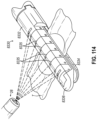
- FIG. 114 depicts a perspective view of a fourth exemplary end effector, shown clamping a tissue with a second configuration of illumination features illuminated;
- FIG. 115 depicts a cross-sectional side view of the end effector of FIG. 114 ;
- FIG. 116 depicts a side view of the end effector of FIG. 114 in use and clamping a tissue, the tissue shown as transparent, with select internal portions of the end effector overlayed for functional clarity;
- FIG. 117 A depicts a cross-sectional side view of a fifth exemplary end effector with the upper jaw and lower jaw in a closed position, shown with select internal portions of the end effector in a first staple firing position and overlayed for functional clarity, shown with a third configuration of illumination features not illuminated;
- FIG. 117 B depicts a cross-sectional side view of the fifth exemplary end effector of FIG. 117 A with the upper jaw and lower jaw in a closed position, shown with select internal portions of the end effector in a second staple firing position and overlayed for functional clarity, shown with the third configuration of illumination features illuminated;
- FIG. 117 C depicts a cross-sectional side view of the fifth exemplary end effector of FIG. 117 A with the upper jaw and lower jaw in a closed position, shown with select internal portions of the end effector in a third staple firing position and overlayed for functional clarity, shown with the third embodiment of illumination features illuminated;
- FIG. 118 depicts an end view of a wedge sled of the fifth exemplary end effector of FIG. 117 A , with select portions of the third exemplary end effector omitted;
- FIG. 119 depicts a perspective view of the lower jaw of the fifth exemplary end effector of FIG. 117 A , with select portions of the fifth exemplary end effector omitted to reveal internal features;
- FIG. 120 depicts a top cross-sectional view of a second exemplary configuration of an elongate shaft of an alternative exemplary surgical instrument that may be used with the robotic surgical system of FIG. 1 , the elongate shaft having a movable feature disposed therein and a fourth configuration of illumination features;
- FIG. 121 A depicts a cross-sectional top view of the elongate shaft of FIG. 120 , with the movable feature in a first position;
- FIG. 121 B depicts a cross-sectional top view of the elongate shaft of FIG. 120 , with the movable feature in a second position;
- FIG. 122 depicts a graphical representation of the output of the fourth configuration of illumination features during a staple firing stroke
- FIG. 123 depicts a perspective view of a staple cartridge of a sixth exemplary end effector, with select portions of the sixth exemplary end effector omitted, the staple cartridge having a fifth configuration of illumination features;
- FIG. 124 depicts a perspective view of a lower jaw of a seventh exemplary end effector, with select portions of the seventh exemplary end effector omitted, the staple cartridge having a sixth configuration of illumination features;
- FIG. 125 A depicts a cross-sectional side view of an eighth exemplary end effector with the upper jaw and lower jaw in a closed position, shown with select internal portions of the end effector in a first staple firing position and overlayed for functional clarity, shown with a seventh configuration of illumination features not illuminated;
- FIG. 125 B depicts a cross-sectional side view of the eighth exemplary end effector of FIG. 125 A with the upper jaw and lower jaw in a closed position, shown with select internal portions of the end effector in a second staple firing position and overlayed for functional clarity, shown with the seventh configuration of illumination features illuminated;
- FIG. 125 C depicts a cross-sectional side view of the eighth exemplary end effector of FIG. 125 A with the upper jaw and lower jaw in a closed position, shown with select internal portions of the end effector in a third staple firing position and overlayed for functional clarity, shown with the seventh configuration of illumination features illuminated;
- FIG. 126 depicts a top cross-sectional view of a third exemplary configuration of an elongate shaft of an alternative exemplary surgical instrument that may be used with the robotic surgical system of FIG. 1 , the elongate shaft having a movable feature disposed therein and an eighth configuration of illumination features;
- FIG. 127 A depicts a cross-sectional top view of the elongate shaft of FIG. 126 , with the movable feature in a first position;
- FIG. 127 B depicts a cross-sectional top view of the elongate shaft of FIG. 126 , with the movable feature in a second position;
- FIG. 128 depicts an end cross-sectional view of a portion of a fourth exemplary configuration of an elongate shaft of an alternative exemplary surgical instrument that may be used with the robotic surgical system of FIG. 1 , the elongate shaft having a movable feature disposed therein and a ninth configuration of illumination features;
- FIG. 129 depicts a side cross-sectional view of a portion of the elongate shaft of FIG. 128 , shown with a portion of the ninth configuration of illumination features in an illuminated state;
- FIG. 130 depicts a perspective view of the elongate shaft of FIG. 128 coupled with a ninth exemplary end effector, shown with the end effector clamping a tissue with a portion of the ninth configuration of illumination features illuminated;
- FIG. 131 depicts a side cross-sectional view of a portion of the elongate shaft and end effector of FIG. 30 , shown with a portion of the ninth configuration of illumination features illuminated;
- FIG. 132 depicts a perspective view of a tenth exemplary end effector, shown clamping a tissue and having a portion of a tenth configuration of illumination features illuminated;
- FIG. 133 depicts an end cross-sectional view of a portion of the end effector of FIG. 132 ;
- FIG. 134 depicts a perspective view of a lower jaw of an eleventh exemplary end effector, with select portions of the eleventh exemplary end effector omitted or transparent to reveal internal features, the lower jaw having an eleventh configuration of illumination features;
- FIG. 135 depicts a bottom perspective view of the end effector of FIG. 134 ;
- FIG. 136 depicts an end cross-sectional view of the end effector of FIG. 134 ;
- FIG. 137 depicts a first graphical representation of the thermochromic output of the illumination features of the end effector of FIG. 134 during a firing stroke, the first graphical representation illustrating the relationship between applied voltage and temperature;
- FIG. 138 depicts a second graphical representation of the thermochromic output of the illumination features of the end effector of FIG. 134 during a firing stroke, the second graphical representation illustrating the relationship between temperature and time;
- FIG. 139 depicts a second exemplary driving assembly, the driving assembly having a twelfth configuration of illumination features
- FIG. 140 depicts a pivotable anvil configured for use with the driving assembly of FIG. 139 ;
- FIG. 141 depicts a top plan view of an exemplary drive system that may be used with the surgical instrument of FIG. 4 ;
- FIG. 142 depicts a perspective view of the drive system of FIG. 141 ;
- FIG. 143 A depicts a top plan view of an exemplary alternative drive system that may be used with the surgical instrument of FIG. 4 , the drive system in a single drive configuration;
- FIG. 143 B depicts another top plan view of the drive system of FIG. 143 A , the drive system in a first multiple drive configuration;
- FIG. 143 C depicts yet another top plan view of the drive system of FIG. 143 A , the drive system in a second multiple drive configuration;
- FIG. 143 D depicts still another top plan view of the drive system of FIG. 143 A , the drive system in a third multiple drive configuration;
- FIG. 144 A depicts a top plan view of another exemplary alternative drive system that may be used with the surgical instrument of FIG. 4 , the drive system in a first drive configuration;
- FIG. 144 B depicts another top plan view of the drive system of FIG. 144 A , the drive system in a second drive configuration;
- FIG. 145 A depicts a detailed top plan view of the drive system of FIG. 144 A , the drive system in the first drive configuration;
- FIG. 145 B depicts another detailed top plan view of the drive system of FIG. 144 A , the drive system in the second drive configuration;
- FIG. 146 A depicts a side elevational view of an exemplary shifting mechanism that may be used with the surgical instrument of FIG. 4 , the shifting mechanism in a single drive configuration;
- FIG. 146 B depicts another side elevational view of the shifting mechanism of FIG. 146 A , the shifting mechanism in a multi-drive configuration
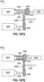
- FIG. 147 A depicts a side elevational view of an exemplary alternative shifting mechanism that may be used with the surgical instrument of FIG. 4 , the shifting mechanism in a single drive configuration;
- FIG. 147 B depicts another side elevational view of the shifting mechanism of FIG. 147 A , the shifting mechanism in a multi-drive configuration
- FIG. 148 depicts a perspective view of another exemplary alternative shifting mechanism that may be used with the surgical instrument of FIG. 4 ;
- FIG. 149 depicts a top plan view of the shifting mechanism of FIG. 148 , the shifting mechanism in a first configuration
- FIG. 150 depicts another top plan view of the shifting mechanism of FIG. 148 , the shifting mechanism in a second configuration
- FIG. 151 depicts a side elevational view of yet another exemplary alternative shifting mechanism that may be used with the surgical instrument of FIG. 4 ;
- FIG. 152 depicts another side elevational view of the shifting mechanism of FIG. 151 , the shifting mechanism being used as a continuously variable transmission;
- FIG. 153 depicts a perspective view of still another exemplary alternative shifting mechanism that may be used with the surgical instrument of FIG. 4 ;
- FIG. 154 depicts an exploded perspective view of a portion of the shifting mechanism of FIG. 153 ;
- FIG. 155 depicts a detailed perspective view of a shift shaft of the shifting mechanism of FIG. 153 ;
- FIG. 156 A depicts a side elevational view of the shifting mechanism of FIG. 153 , the shifting mechanism in a direct drive configuration
- FIG. 156 B depicts a side elevational view of the shifting mechanism of FIG. 153 , the shifting mechanism in a reduction drive configuration
- FIG. 157 depicts a perspective view of still another exemplary alternative shifting mechanism that may be used with the surgical instrument of FIG. 4 ;
- FIG. 158 depicts a perspective cutaway view of the shifting mechanism of FIG. 157 ;
- FIG. 159 depicts a cutaway side elevational view of a proximal base portion of an exemplary alternative surgical instrument that may be used with the robotic surgical system of FIG. 1 ;
- FIG. 160 A depicts a side elevational view of an end effector of the surgical instrument of FIG. 159 , the end effector in a closed configuration
- FIG. 160 B depicts another side elevational view of the end effector of FIG. 160 A , the end effector in a partially open configuration
- FIG. 161 A depicts a side elevational view of an exemplary alterative cable manipulator for use with the surgical instrument of FIG. 159 , the cable manipulator in a first configuration;
- FIG. 161 B depicts another side elevational view of the cable manipulator of FIG. 161 A , the cable manipulator in a second configuration
- FIG. 162 depicts a perspective view of an exemplary bailout mechanism that may be incorporated into the surgical instrument of FIG. 4 ;
- FIG. 163 depicts a perspective view of a shuttle of the bailout mechanism of FIG. 162 ;
- FIG. 164 depicts another perspective view of the shuttle of FIG. 163 ;
- FIG. 165 depicts a perspective view of another exemplary bailout mechanism that may be incorporated into the surgical instrument of FIG. 4 ;
- FIG. 166 depicts a perspective view of a shuttle of the bailout mechanism of FIG. 165 ;
- FIG. 167 depicts a partial top plan view of the shuttle of FIG. 166 ;
- FIG. 168 depicts a perspective view of an axial strengthening feature that may be incorporated into the surgical instrument of FIG. 4 ;
- FIG. 169 A depicts a perspective view of a manual drive wheel that may be incorporated into the bailout mechanisms of FIG. 162 or 163 , with an arm of the manual drive wheel in a retracted position;
- FIG. 169 B depicts another perspective view of the manual drive wheel of FIG. 169 A , with the arm of the manual drive wheel in an extended position;
- FIG. 170 depicts a perspective view of another manual drive wheel that may be incorporated into the bailout mechanisms of FIG. 162 or 163 ;
- FIG. 171 depicts an exploded perspective view of the manual drive wheel of FIG. 170 ;
- FIG. 172 depicts another perspective view of the manual drive wheel of FIG. 170 , with the manual drive wheel in an engaged position;
- FIG. 173 depicts a perspective view of a distal portion of an exemplary push rod for use with the surgical instrument of FIG. 4 ;
- FIG. 174 depicts a side elevational view of the distal portion of the push rod of FIG. 173 ;
- FIG. 175 A depicts a side elevational view of the distal portion of the push rod of FIG. 12 , showing the distal portion of the push rod in a laterally deflected state;
- FIG. 175 B depicts a side elevational view of the distal portion of the push rod of FIG. 12 , showing the distal portion of the push rod in a longitudinally compressed state;
- FIG. 176 depicts a perspective view of a distal portion of another exemplary push rod for use with the surgical instrument of FIG. 4 ;
- FIG. 177 depicts a side elevational view of the distal portion of the push rod of FIG. 176 ;
- FIG. 178 A depicts a side elevational view of the distal portion of the push rod of FIG. 176 , showing the distal portion of the push rod in a laterally deflected state;
- FIG. 178 B depicts a side elevational view of the distal portion of the push rod of FIG. 176 , showing the distal portion of the push rod in a longitudinally compressed state;
- FIG. 179 depicts a perspective view of a distal portion of another exemplary push rod for use with the surgical instrument of FIG. 4 ;
- FIG. 180 depicts a side elevational view of a distal portion of another exemplary push rod for use with the surgical instrument of FIG. 4 ;
- FIG. 181 depicts a perspective view of a distal portion of an exemplary actuation assembly, including an exemplary pull rod and another exemplary push rod for use with the surgical instrument of FIG. 4 ;
- FIG. 182 depicts a cross-sectional view of the distal portion of the actuation assembly of FIG. 181 , taken along section line 182 - 182 in FIG. 181 ;
- FIG. 183 depicts a perspective view of a distal portion of the push rod of FIG. 181 ;
- FIG. 184 A depicts a side elevational view of another exemplary push rod for use with the surgical instrument of FIG. 4 , showing the push rod in an undeflected state;
- FIG. 184 B depicts a side elevational view of the push rod of FIG. 184 A , showing the push rod in a laterally deflected state;
- FIG. 185 depicts a perspective view of a link of the push rod of FIG. 184 A ;
- FIG. 186 depicts a partially disassembled perspective view of a distal portion of another exemplary push rod for use with the surgical instrument of FIG. 4 ;
- FIG. 187 depicts a partially disassembled perspective view of a distal portion of another exemplary push rod for use with the surgical instrument of FIG. 4 ;
- FIG. 188 depicts a perspective view of another exemplary driving assembly for use with the surgical instrument of FIG. 4 ;
- FIG. 189 depicts a partially disassembled perspective view of the driving assembly of FIG. 188 .
- proximal and distal are defined herein relative to a human or robotic operator of the surgical instrument.
- proximal refers the position of an element closer to the human or robotic operator of the surgical instrument and further away from the surgical end effector of the surgical instrument.
- distal refers to the position of an element closer to the surgical end effector of the surgical instrument and further away from the human or robotic operator of the surgical instrument.
- spatial terms such as “clockwise,” “counterclockwise,” “inner,” “outer,” “upper,” “lower,” “lateral,” and the like also are used herein for reference to relative positions and directions. Such terms are used below with reference to views as illustrated for clarity and are not intended to limit the invention described herein.
- aspects of the present examples described herein may be integrated into a robotically-enabled medical system, including as a robotic surgical system, capable of performing a variety of medical procedures, including both minimally invasive, such as laparoscopy, and non-invasive, such as endoscopy, procedures.
- a robotic surgical system capable of performing a variety of medical procedures, including both minimally invasive, such as laparoscopy, and non-invasive, such as endoscopy, procedures.
- the robotically-enabled medical system may be capable of performing bronchoscopy, ureteroscopy, gastroscopy, etc.
- FIG. 1 shows a top plan view of an exemplary robotic surgical system ( 10 ) that may be used for performing a diagnostic or surgical procedure on a patient ( 12 ) who is lying down on an operating table ( 14 ).
- Robotic surgical system ( 10 ) may be constructed and operable in accordance with at least some of the teachings of U.S. Pat. No. 9,839,487, entitled “Backup Latch Release for Surgical Instrument,” issued Dec. 12, 2017; U.S. Pat. No. 10,485,621, entitled “Sterile Barrier Between Surgical Instrument and Teleoperated Actuator,” issued Nov. 26, 2019; U.S. Pat. No. 10,806,530, entitled “System and Method for Patient-Side Instrument Control,” issued Oct. 20, 2020; U.S. Pat. No.
- 2019/0239877 entitled “Wrist Architecture,” published Aug. 8, 2019, issued as U.S. Pat. No. 11,234,700 on Feb. 1, 2022; U.S. Pub. No. 2019/0201150, entitled “Push-Pull Surgical Instrument End Effector Actuation Using Flexible Tension Member,” published Jul. 4, 2019, issued as U.S. Pat. No. 11,076,926 on Jun. 1, 2021; U.S. Pub. No. 2019/0282233, entitled “Stapler Cartridge With an Integral Knife,” published Sep. 19, 2019, issued as U.S. Pat. No. 11,147,552 on Oct. 19, 2021; U.S. Pub. No.
- Robotic surgical system ( 10 ) may include a surgeon's console ( 16 ) for use by a surgeon ( 18 ) during a surgical procedure.
- One or more assistants ( 20 ) may also participate in the procedure.
- Robotic surgical system ( 10 ) may include a patient side cart ( 22 ) (i.e., a surgical robot) and an electronics cart ( 24 ).
- Patient side cart ( 22 ) may manipulate at least one surgical instrument ( 26 ) (also referred to as a “tool assembly” or “tool”) through an incision in the body of patient ( 12 ) while surgeon ( 18 ) views the surgical site through surgeon's console ( 16 ).
- surgical instrument(s) ( 26 ) and an imaging device may be removably coupled with patient side cart ( 22 ).
- Electronics cart ( 24 ) may be used to process the images of the surgical site for subsequent display to the surgeon ( 18 ) through surgeon's console ( 16 ).
- Electronics cart ( 24 ) may be coupled with endoscope ( 28 ) and may include a processor ( 38 ) (shown schematically) to process captured images for subsequent display, such as to surgeon ( 18 ) on the surgeon's console ( 16 ), on a display ( 40 ) of electronics cart ( 24 ), or another suitable display located locally and/or remotely.
- the images may also be processed by a combination of electronics cart ( 24 ) and processor ( 38 ), which may be coupled together to process the captured images jointly, sequentially, and/or combinations thereof.
- Electronics cart ( 24 ) may overlay the captured images with a virtual control interface prior to displaying combined images to the surgeon ( 18 ) via surgeon's console ( 16 ).
- FIG. 2 shows a perspective view of surgeon's console ( 16 ).
- Surgeon's console ( 16 ) includes a left eye display ( 32 ) and a right eye display ( 34 ) for presenting surgeon ( 18 ) with a coordinated stereo view of the surgical site that enables depth perception.
- Surgeon's console ( 16 ) includes one or more input control devices ( 36 ) causing patient side cart ( 22 ) (shown in FIG. 1 ) to manipulate one or more surgical instruments ( 26 ).
- Input control devices ( 36 ) may provide the same degrees of freedom as their associated surgical instruments ( 26 ) (shown in FIG. 1 ) to provide surgeon ( 18 ) with telepresence, or the perception that the input control devices ( 36 ) are integral with surgical instruments ( 26 ).
- position, force, and tactile feedback sensors may be employed to transmit position, force, and tactile sensations from surgical instruments ( 26 ) back to the surgeon's hands through input control devices ( 36 ).
- surgeon's console ( 16 ) may be located in the same room as the patient so that surgeon ( 18 ) may directly monitor the procedure, be physically present if necessary, and speak to an assistant directly rather than over the telephone or other communication medium.
- surgeon ( 18 ) may be located in a different room, a completely different building, or other remote location from the patient allowing for remote surgical procedures.
- FIG. 3 shows patient side cart ( 22 ) that manipulates surgical instruments ( 26 ).
- An image of the surgical site may be obtained by endoscope ( 28 ), which may include a stereoscopic endoscope.
- Manipulation is provided by robotic mechanisms, shown as robotic arms ( 42 ) that include at least one robotic joint ( 44 ) and an output coupler (not shown) that is configured to removable secure surgical instrument ( 26 ) with robotic arm ( 42 ).
- Endoscope ( 28 ) and surgical tools ( 26 ) may be positioned and manipulated through incisions in the patient so that a kinematic remote center is maintained at the incision to minimize the size of the incision.
- Images of the surgical site may include images of the distal ends of the surgical instruments ( 26 ) when they are positioned within the field-of-view of the endoscope ( 28 ).
- Patient side cart ( 22 ) may output the captured images for processing outside electronics cart ( 24 ).
- the number of surgical instruments ( 26 ) used at one time will generally depend on the diagnostic or surgical procedure and the space constraints within the operating room, among other factors.
- assistant(s) ( 20 ) may remove surgical instrument ( 26 ) from patient side cart ( 22 ) and replace surgical instrument ( 26 ) with another surgical instrument ( 26 ) from a tray ( 30 ) (shown in FIG. 1 ) in the operating room.
- FIGS. 4 - 5 show an exemplary surgical instrument ( 110 ) that may be mounted on and used with patient side cart ( 22 ) shown in FIG. 3 .
- Surgical instrument ( 110 ) can have any of a variety of configurations capable of performing one or more surgical functions.
- surgical instrument ( 110 ) includes an instrument base ( 112 ), a shaft assembly ( 114 ) extending distally from instrument base ( 112 ), and an end effector ( 116 ) at a distal end of shaft assembly ( 114 ).
- An articulation joint ( 132 ) is disposed between shaft assembly ( 114 ) and end effector ( 116 ). As shown in phantom lines in FIG.
- Instrument base ( 112 ) includes an attachment interface ( 118 ) that includes input couplers ( 130 ) that are configured to interface with and be driven by corresponding output couplers (not shown) of robotic arm ( 42 ) of patient side cart ( 22 ).
- FIG. 5 shows an enlarged perspective view of instrument base ( 112 ) of surgical instrument ( 110 ).
- Instrument base ( 112 ) includes a drive system ( 120 ) mounted on a chassis ( 122 ) and having one or more actuators for actuating end effector ( 116 ) to clamp, staple, and cut tissue, and for articulating end effector ( 116 ) relative to a longitudinal axis defined by shaft assembly ( 114 ).
- Drive system ( 120 ) may include a manual actuator ( 124 ), which is shown in the form of a knob configured to be manually rotated.
- Manual actuator ( 124 ) may engage other components of surgical instrument ( 110 ) to serve as a “bailout” mechanism to obtain a desired movement in end effector ( 116 ) without powered actuation of drive system ( 120 ).
- Shaft assembly ( 114 ) may include additional drive components, such as portions of a drive train ( 126 ), that may couple instrument base ( 112 ) to a moveable feature ( 128 ) of shaft assembly ( 114 ) that may be coupled to end effector ( 116 ).
- Shaft assembly ( 114 ) may be configured for use with a variety of interchangeable end effectors ( 116 ), such as a cutter, grasper, a cautery tool, a camera, a light, or a surgical stapler, for example.
- FIG. 6 shows a cross-sectional side view of end effector ( 116 ) of surgical instrument ( 110 ).
- End effector ( 116 ) extends distally from a distal end of shaft assembly ( 114 ).
- end effector ( 116 ) comprises a surgical stapler, which may also be referred to herein as an “endocutter,” configured to clamp, cut, and staple tissue.
- end effector ( 116 ) includes opposing upper and lower jaws ( 150 , 152 ) configured to move relative to one another between open and closed positions for clamping and releasing tissue.
- Upper and lower jaws ( 150 , 152 ) may be configured to pivot and thereby actuate end effector ( 116 ) between open and closed positions.
- Lower jaw ( 152 ) includes a staple cartridge tray ( 177 ) which accepts and supports a stapling assembly in the form of a removable staple cartridge ( 154 ) therein.
- a stapling assembly in the form of a removable staple cartridge ( 154 ) therein.
- an entirety or a portion of the stapling assembly may be non-removably integrated into the structure of end effector ( 116 ).
- lower jaw ( 152 ) is pivotable relative to upper jaw ( 150 ) to move between an open, unclamped position and a closed, clamped position.
- upper jaw ( 150 ) may move relative to lower jaw ( 152 ) (e.g., similar to end effector ( 210 ) of FIGS. 9 - 10 ).
- both and upper and lower jaws ( 150 , 152 ) may move to actuate end effector ( 116 ) between open and closed positions.
- lower jaw ( 152 ) is referred to as a “cartridge jaw” or “channel jaw,” and upper jaw ( 150 ) is referred to as an “anvil jaw.”
- Upper jaw ( 150 ) defines a surface that has a plurality of pockets (not shown) and operates as an anvil to deform staples ejected from staple cartridge ( 154 ) during operation.
- Staple cartridge ( 154 ) is replaceable, for example, by removing a used staple cartridge ( 154 ) from end effector ( 116 ) and inserting a new staple cartridge ( 154 ) into lower jaw ( 152 ).
- Staple cartridge ( 154 ) includes a staple cartridge body ( 156 ) that houses a firing assembly ( 158 ), a plurality of staple drivers ( 160 ) (also referred to as staple pushers), and a plurality of staples ( 162 ). As shown in FIGS.
- end effector ( 116 ) includes a driving assembly ( 164 ) that includes a pusher member ( 166 ) that is operatively coupled with an actuation mechanism via a push rod ( 168 ).
- firing assembly ( 158 ) includes a wedge sled ( 170 ) (also referred to as a staple pushing shuttle), and a knife member ( 172 ).
- FIG. 7 shows a top view of staple cartridge body ( 156 ).
- Staple cartridge body ( 156 ) includes an array of staple accommodating apertures ( 174 ) (also known as openings) extending through an upper deck ( 188 ) of staple cartridge body ( 156 ).
- Each aperture ( 174 ) slidably houses a respective staple ( 162 ) in an unformed state and a free end of a corresponding staple driver ( 160 ) positioned beneath the unformed staple ( 162 ).
- Staple cartridge ( 154 ) includes proximal and distal ends ( 176 , 178 ).
- staples ( 162 ) are sequentially deployed from apertures ( 174 ) by staple drivers ( 160 ) starting at proximal end ( 176 ) and advancing toward distal end ( 178 ).
- FIG. 8 shows pusher member ( 166 ) as including first and second flanges ( 184 , 185 ).
- First flange ( 184 ) is configured to be received in a longitudinal slot ( 186 ) (shown in FIG. 6 ) of upper jaw ( 150 ) and second flange ( 185 ) is configured to be received in a longitudinal slot ( 187 ) (shown in FIG. 6 ) of staple cartridge body ( 156 ) of lower jaw ( 152 ).
- First and second flanges ( 184 , 185 ) move along longitudinal slots ( 186 , 187 ) during actuation of pusher member ( 166 ).
- pusher member ( 166 ) may include a single flange (e.g., omitting first flange ( 184 )). As shown, longitudinal slot ( 186 ) is generally enclosed and longitudinal slot ( 187 ) opens to an exterior surface of lower jaw ( 152 ).
- FIG. 9 shows a perspective view of firing assembly ( 158 ), which is configured to be slidably received within the proximal end ( 176 ) of staple cartridge body ( 156 ) in a longitudinal direction prior to engaging staple drivers ( 160 ) and staples ( 162 ).
- Wedge sled ( 170 ) of firing assembly ( 158 ) slidingly interfaces with staple cartridge body ( 156 ). More specifically, wedge sled ( 170 ) advances distally along staple cartridge body ( 156 ) such that ramp portions ( 182 ) of wedge sled ( 170 ) contact staple drivers ( 160 ).
- Staple drivers ( 160 ) push staples ( 162 ) out of apertures ( 174 ) of staple cartridge body ( 156 ) to penetrate through and staple tissue clamped between staple cartridge body ( 156 ) and upper jaw ( 150 ).
- An initial distal actuation of pusher member ( 166 ) may move pusher member ( 166 ) into contact with wedge sled ( 170 ), with further actuation pushing staples ( 162 ) transversely out of staple cartridge body ( 156 ).
- knife member ( 172 ) is housed within staple cartridge body ( 156 ).
- the position of knife member ( 172 ) is controlled during a first portion of the movement of wedge sled ( 170 ) from proximal end ( 176 ) of staple cartridge body ( 156 ) to distal end ( 178 ) of staple cartridge ( 154 ), so that a cutting edge ( 194 ) of knife member ( 172 ) extends through vertical slot ( 180 ).
- Vertical slot ( 180 ) accommodates cutting edge ( 194 ) of knife member ( 172 ) as firing assembly ( 158 ) is moved toward distal end ( 178 ) of staple cartridge ( 154 ).
- Wedge sled ( 170 ) includes a guide member ( 190 ) that provides a bearing surface that cooperates with a similarly shaped surface of staple cartridge body ( 156 ) to guide wedge sled ( 170 ).
- Guide member ( 190 ) extends from a vertical rib member ( 192 ) of wedge sled ( 170 ), which forms a central portion of wedge sled ( 170 ).
- knife member ( 172 ), or at least cutting edge ( 194 ) may be retracted below upper deck ( 188 ) of staple cartridge body ( 156 ) prior to firing assembly ( 158 ) reaching its distal most position adjacent to distal end ( 178 ) of staple cartridge ( 154 ).
- FIGS. 10 - 11 show a second exemplary end effector ( 210 ), in an open position, that is configured to compress, cut, and staple tissue.
- End effector ( 210 ) may be configured for use with surgical instrument ( 110 ) of FIG. 4 , or with surgical instruments of alternative constructions.
- End effector ( 210 ) may be constructed and operable in accordance with at least some of the teachings of U.S. patent application Ser. No. 16/916,295, entitled “Surgical Stapler Cartridge Retainer with Ejector Feature,” filed Aug. 3, 2020, issued as U.S. Pat. No. 11,497,494 on Nov. 15, 2022; the disclosure of which is incorporated by reference herein in its entirety.
- End effector ( 210 ) of the present example includes a lower jaw ( 212 ) and an upper j aw in the form of a pivotable anvil ( 214 ).
- Lower jaw ( 212 ) may be constructed and operable in accordance with at least some of the teachings of U.S. Pat. No. 9,808,248, entitled “Installation Features for Surgical Instrument End Effector Cartridge,” issued Nov. 7, 2017, the disclosure of which is incorporated by reference herein in its entirety.
- Anvil ( 214 ) may be constructed and operable in accordance with at least some of the teachings of U.S. Pat. No. 10,092,292, entitled “Staple Forming Features for Surgical Stapling Instrument,” issued Oct. 9, 2018, the disclosure of which is incorporated by reference herein in its entirety.
- FIG. 10 shows end effector ( 210 ), where anvil ( 214 ) is pivoted to an open position and a firing beam ( 216 ) is proximally positioned, allowing an unspent staple cartridge ( 218 ) to be removably installed into a channel of lower jaw ( 212 ).
- Staple cartridge ( 218 ) includes a cartridge body ( 220 ), which presents an upper deck ( 222 ) and is coupled with a lower cartridge tray ( 224 ).
- a vertical slot ( 226 ) is formed through part of staple cartridge ( 218 ) and opens upwardly through upper deck ( 222 ).
- One or more rows of staple apertures ( 228 ) are formed through upper deck ( 222 ) on one side of vertical slot ( 226 ), with one or more rows of staple apertures ( 228 ) being formed through upper deck ( 222 ) on the other side of vertical slot ( 226 ).
- End effector ( 210 ) is closed by distally advancing a closure tube (not shown) and a closure ring ( 230 ). Firing beam ( 216 ) is then advanced distally so that an upper pin of firing beam ( 216 ) enters longitudinal anvil slot ( 234 ).
- firing beam ( 216 ) During firing, cutting edge ( 240 ) of firing beam ( 216 ) enters vertical slot ( 226 ) toward distal end ( 242 ) of staple cartridge ( 218 ), severing tissue clamped between staple cartridge ( 218 ) and anvil ( 214 ).
- wedge sled ( 238 ) presents inclined cam surfaces that urge staple drivers ( 244 ) upwardly as wedge sled ( 238 ) is driven distally through staple cartridge ( 218 ).
- a firing beam cap ( 246 ) slidably engages a lower surface of lower jaw ( 212 ).
- Wedge sled ( 238 ) is movable longitudinally within staple cartridge ( 218 ), while staple drivers ( 244 ) are movable vertically within staple cartridge ( 218 ).
- a middle pin ( 248 ) and pusher block ( 236 ) of firing beam ( 216 ) together actuate staple cartridge ( 218 ) by entering into vertical slot ( 226 ) within staple cartridge ( 218 ), driving wedge sled ( 238 ) distally into upward camming contact with staple drivers ( 244 ) that in turn drive staples ( 250 ) out through staple apertures ( 228 ) and into forming contact with staple forming pockets ( 252 ) on the inner surface of anvil ( 214 ). Additional examples of alternative surgical instruments and/or associated features are described in U.S.
- the exemplary methods and configurations described below provide such enhanced capabilities.
- FIG. 12 shows another exemplary robotic surgical system ( 310 ) that includes a robotic arm ( 312 ) and a surgical instrument, shown in the form of surgical instrument ( 110 ) which is configured to removably couple with robotic arm ( 312 ).
- Robotic surgical system ( 310 ) is similar to robotic surgical system ( 10 ) with differences described below.
- robotic arm ( 312 ) may be similar to robotic arm ( 42 ) described above with reference to FIGS. 1 - 4 .
- Robotic arm ( 312 ) may suitably interact with robotic surgical system ( 310 ) such that a medical professional operator may utilize robotic surgical system ( 310 ) to control instrument ( 110 ) via robotic arm ( 312 ), input control devices ( 36 ) of surgeon's console ( 16 ), and any other suitable intermediate components as would be apparent to one skilled in the art in view of the teachings described herein.
- surgical instrument ( 110 ) includes shaft assembly ( 114 ), driving assembly ( 164 ), and end effector ( 116 , 210 ).
- Driving assembly ( 164 ) may extend through at least a portion of shaft assembly ( 114 ) and end effector ( 116 , 210 ).
- Driving assembly ( 164 ) is operable to staple and cut tissue based on instruction from motor controller ( 320 ).
- End effector ( 116 , 210 ) includes first and second jaws ( 150 , 152 , 212 , 214 ).
- At least one of first or second jaws ( 150 , 152 , 212 , 214 ) is configured to pivot relative to the other of first or second jaws ( 150 , 152 , 212 , 214 ).
- End effector ( 116 , 210 ) is operatively coupled with shaft assembly ( 114 ).
- First jaw ( 150 , 212 ) includes an anvil, and second jaw ( 152 , 214 ) is configured to receive staple cartridge ( 154 , 218 ) that includes staples ( 250 ).
- Lockout assembly ( 314 ) may be moved between a lockout configuration and a non-lockout configuration. The lockout configuration prevents actuation of firing assembly ( 158 ). In the lockout configuration, the complete firing of end effectors ( 116 , 210 ) is prevented. Conversely, the non-lockout configuration allows for actuation of firing assembly ( 158 ).
- Robotic arm ( 312 ) includes at least one motor ( 316 ), a sensor assembly ( 318 ), and a motor controller ( 320 ).
- One or more output couplers ( 322 ) of robotic arm ( 312 ) are configured to selectively couple with at least one or more input couplers ( 130 ) of surgical instrument ( 110 ).
- Input coupler ( 130 ) is configured to interface with and be driven by output coupler ( 322 ) of robotic arm ( 312 ).
- Output coupler ( 322 ) and input coupler ( 130 ) may include any suitable components as would be apparent to one skilled in the art in view of the teachings herein.
- Motor controller ( 320 ) may be in communication with input control devices ( 36 ) of surgeon's console ( 16 ).
- any suitable number of input couplers ( 130 ) and any suitable number of output couplers ( 322 ) may be utilized as would be apparent to one skilled in the art in view of the teachings herein. While not shown, a first output coupler ( 322 ) may couple with a first input coupler ( 130 ) and a second output coupler (not shown) may couple with a second input coupler (not shown). For example, the second input coupler may be controlled by a second motor to perform separate functions.
- motor ( 316 ) and the respective output coupler ( 322 ) and input coupler ( 130 ) may be utilized to actuate firing beam ( 216 ); while second motor (not shown) and the respective output coupler (not shown) and second input coupler (not shown) may be utilized to actuate closure tube (not shown) and closure ring ( 230 ).
- Motor ( 316 ) is configured to actuate driving assembly ( 164 ) to deploy staples from staple cartridge ( 154 , 218 ).
- Motor ( 316 ) is configured to drive firing assembly ( 158 ) within end effector ( 116 , 210 ) to advance knife through end effector ( 116 , 210 ) or fire a plurality of staples ( 250 ) out of staple cartridge ( 154 , 218 ).
- Motor controller ( 320 ) is in communication with motor ( 316 ).
- Sensor assembly ( 318 ) is configured to sense values of interrelated trigger related to operation of motor ( 316 ).
- sensor assembly ( 318 ) is disposed within robotic arm ( 312 ); however, it is envisioned that sensor assembly ( 318 ) may be positioned in a variety of locations that are suitable to instruct the operation of motor ( 316 ).
- sensor assembly may be disposed within surgical instrument ( 110 ) (e.g., in or adjacent to end effector ( 116 , 210 )).
- Sensor assembly ( 318 ) may include one or more of a force sensor, a current sensor, a temperature sensor, or a position sensor. Data obtained from sensor assembly ( 318 ) may be stored on storage device ( 326 ) for later access by motor controller ( 320 ).
- Motor controller ( 320 ) may also be in communication with storage device ( 326 ) such that motor controller ( 320 ) may communicate data to storage device ( 326 ), and such that motor controller ( 320 ) may access and utilize data stored on storage device ( 326 ).
- Motor controller ( 320 ) and storage device ( 326 ) may contain any suitable number of components as would be apparent to one skilled in the art in view of the teachings herein.
- Motor controller ( 320 ) may utilize data contained in storage device ( 326 ) in order to establish operational parameters for robotic arm ( 342 ) while controlling a specific instrument ( 110 ).
- Motor controller ( 320 ) may recall and utilize data stored on storage device ( 326 ) related to specific instruments ( 110 ) when that specific instrument ( 110 ) is coupled to robotic arm ( 312 ) for exemplary use in accordance with the description herein.
- storage device ( 326 ) may be configured to store predetermined thresholds (e.g., force thresholds, temperature thresholds, voltage thresholds) pertaining to the specific instrument ( 110 ) in accordance with the teachings herein.
- Storage device ( 326 ) may be configured to store information related to a specific instrument ( 110 ), such as any suitable data accumulated during exemplary use of a specific instrument ( 110 ) as would be apparent to one skilled in the art in view of the teachings herein.
- a specific instrument ( 110 ) may have an identifiable chip or other electronic device that notifies motor controller ( 320 ) of the specific instrument ( 110 ) that is coupled with robotic arm ( 342 ), therefore allowing motor controller ( 320 ) to track the specific instrument ( 110 ) and data stored on storage device ( 326 ) related to the specific instrument ( 110 ).
- the specific instrument ( 110 ) may include its own storage device ( 326 ) that establishes communication with motor controller ( 320 ) when instrument ( 110 ) is initially coupled with robotic arm ( 312 ). In such instances, information regarding prior use of a specific instrument ( 110 ) may be stored on that instrument's specific storage device and accessed by motor controller ( 320 ) when the specific instrument ( 110 ) is coupled to robotic arm ( 312 ).
- storage device ( 326 ) is housed within robotic arm ( 312 ), storage device ( 326 ) may be associated with any suitable component as would be apparent to one skilled in the art in view of the teachings herein.
- storage device ( 326 ) may be housed within instrument ( 110 ) such that storage device ( 326 ) may selectively establish communication with motor controller ( 320 ) while instrument ( 110 ) is coupled to robotic arm ( 312 ).
- storage device ( 326 ) may be associated with surgeon's console ( 16 ).
- multiple storage devices ( 326 ) may be utilized, each associated with various components, such that each storage device ( 326 ) stores data related to the respective specific component.
- method ( 410 ) includes exemplary steps ( 412 , 414 , 416 , 418 , 420 ).
- motor controller ( 320 ) may activate motor ( 316 ) to distally advance driving assembly ( 164 ) into contact with firing assembly ( 158 ).
- interrelated triggers may be measured or otherwise detected. In some versions, the values of the interrelated triggers may be detected using sensor assembly ( 318 ). The interrelated triggers affect at least one motor control parameter.
- motor controller ( 320 ) may determine whether the measured values of interrelated triggers exceed predetermined thresholds.
- the predetermined thresholds may include a measured firing motor force that exceeds a maximum firing motor force threshold of motor ( 316 ), a measured temperature that exceeds a maximum temperature threshold of motor ( 316 ), a measured current that exceeds a maximum current threshold of motor ( 316 ) and/or a measured distance exceeds the lockout value (indicating lockout assembly ( 314 ) is in the non-lockout configuration).
- the interrelated triggers may include firing motor force, firing motor current, or firing motor temperature, and/or duty cycle.
- any one of the triggers referenced in FIGS. 14 - 22 may be used in combination with another one or more triggers referenced in FIGS. 14 - 22 .
- Using multiple triggers in combination may provide additional benefits, and may have a cumulative effect that is different than the triggers being assessed and modified separately. In other words, there are cooperative benefits associated with modifying the performance of motor ( 316 ) using multiple trigger variables in combination.
- motor controller ( 320 ) continues operation according to a predetermined motion profile. However, at step ( 420 ), if one or more of the measured values of interrelated triggers do exceed the predetermined thresholds, motor controller ( 320 ) may modify at least one motor control parameter of motor ( 316 ). Exemplary motor control parameters may include, for example, a motion profile instituted by motor controller ( 320 ) using motor ( 316 ), a waiting period where power to motor ( 316 ) is reduced or stopped, or differing thresholds based on whether driving assembly ( 164 ) is distally advancing or proximally retracting.
- motor controller ( 320 ) is configured to modify two or more motor control parameters.
- the motor control parameters may cooperate to determine max control motions, waits, or change in operation.
- the control parameters may include wait time, alternating cycle rate, speed control, or changing the threshold limits.
- the motion profile may be sustained or intermittent pulse of motor power to change performance of driving assembly ( 164 ) (see FIG. 8 ) or firing beam ( 216 ) (see FIG. 11 ) on end effector ( 116 , 210 ).
- motor controller ( 320 ) is configured to withhold modification of at least one motor control parameter until each of the values of the first and second triggers exceed their respective predetermined thresholds. In some versions, the motor controller ( 320 ) is configured to modify one motor control parameter(s) differently in response to each of the values of the first and second interrelated trigger exceeding the predetermined thresholds as compared to a single one of the interrelated triggers exceeding the respective predetermined threshold.
- driving assembly ( 164 ) or firing beam ( 216 ) may become undesirably stuck due to frictional binding in a longitudinal position relative to staple cartridge ( 154 , 218 ) such that driving assembly ( 164 ) or firing beam ( 216 ) relative to staple cartridge ( 154 , 218 ) is inhibited beyond a tolerable degree.
- driving assembly ( 164 ) or firing beam ( 216 ) relative to staple cartridge ( 154 , 218 ) is inhibited beyond a tolerable degree.
- proximal retraction of pusher member ( 166 ) see FIG.
- flanges ( 184 , 185 ) may overly engage or dig into portions of staple cartridge ( 154 ) and/or jaws ( 150 , 152 ) defining associated longitudinal slots ( 186 , 187 ), thereby inhibiting suitable movement due to an undesirable amount of frictional binding.
- upper pin ( 232 ) or firing beam cap ( 246 ) may overly engage or dig into portions of staple cartridge ( 218 ) defining longitudinal anvil slot ( 234 ) or lower surface of lower jaw ( 212 ), respectively, thereby inhibiting suitable movement due to an undesirable amount of frictional binding. It is desirable for motor controller ( 320 ) to operate motor ( 316 ) in a manner that minimized or overcomes these issues.
- method ( 510 ) may include exemplary steps ( 512 , 514 , 516 , 518 , 520 , 522 , 524 , 526 , 528 , 530 , 532 , 533 , 534 , 536 , 538 , 540 , 542 , 544 , 546 ). While FIGS. 14 - 15 are described below with reference to the structures of FIGS. 1 - 9 , method ( 510 ) may also be used with the structures of FIGS. 10 - 11 .
- motor controller ( 320 ) to activate motor ( 316 ) may distally advance driving assembly ( 164 ).
- motor controller ( 320 ) may activate motor ( 316 ) so that driving assembly ( 164 ) contacts firing assembly ( 158 ).
- motor controller ( 320 ) may activate motor ( 316 ) to distally advance driving assembly ( 164 ) and firing assembly ( 158 ).
- firing motor force may be measured. This firing motor force may be measured by motor controller ( 320 ) interpreting data produced by motor ( 316 ) during operation and/or through the use of a sensor assembly ( 318 ) operatively coupled with motor ( 316 ) and motor controller ( 320 ).
- motor controller ( 320 ) may determine whether the measured firing motor force exceeds the maximum advancement firing motor force threshold.
- Threshold values may be stored in storage device ( 326 ) for retrieval by motor controller ( 320 ).
- motor ( 316 ) may continue on using a predetermined firing sequence until completion of the firing sequence.
- steps ( 518 , 520 , 522 ) may be repeated as described above (one or more times) to repeatedly determine whether the measured firing motor force exceeds the maximum advancement firing motor force.
- step ( 526 ) if the measured firing motor force exceeds the maximum advancement firing motor force threshold as determined by motor controller ( 320 ), motor controller ( 320 ) may instruct motor ( 316 ) to use algorithmic bumping or a soft start.
- algorithmic bumping 558 , 562 ) repeatedly provides power to motor ( 316 ) then stop power to motor ( 316 ).
- motor controller ( 320 ) gradually increases power to motor ( 316 ) (e.g., by incrementally stepping up the power to motor ( 316 )).
- firing motor force may be measured, similar to step ( 518 ).
- motor controller ( 320 ) may determine whether the measured firing motor force exceeds the maximum advancement firing motor force threshold, similar to step ( 520 ).
- step ( 532 ) if the measured firing motor force does not exceed the maximum advancement firing motor force threshold as determined motor controller ( 320 ), motor ( 316 ) may continue on until completion of the firing sequence.
- steps ( 528 , 530 , 532 ) may be repeated (one or more times) to determine whether the measured firing motor force exceeds the maximum advancement firing motor force.
- step ( 534 ) if the measured firing motor force exceeds the maximum advancement firing motor force threshold as determined by motor controller ( 320 ), motor controller ( 320 ) may instruct motor ( 316 ) to retract driving assembly ( 164 ) in a proximal direction, which is opposite to the distal direction of advancement.
- Plots ( 550 , 552 ) of FIG. 15 show comparisons of motor power (as a percentage of maximum power) and firing motor force during retraction of driving assembly ( 164 ).
- Time (t 0 ) refers to the time when driving assembly ( 164 ) starts being retracted, while time (t 9 ) refers to the time when driving assembly ( 164 ) is fully retracted.
- motor ( 316 ) optionally pauses or begins retracting driving assembly ( 164 ) based on instructions from motor controller ( 320 ). For example, at time (t 0 ), shown by line ( 554 ) in plot ( 550 ), power to motor ( 316 ) may be approximately equal to zero to implement an optional waiting period. As shown, motor controller ( 320 ) instructs motor ( 316 ) to incrementally increase motor power using a soft start ( 556 ).
- firing motor force may be measured, similar to step ( 518 ).
- motor controller ( 320 ) may instruct motor ( 316 ) to turn off or activate algorithmic bumping. It may be desirable to have different values for the maximum retraction firing motor force threshold as compared to the maximum advancement firing motor force threshold. In some versions, the maximum retraction firing motor force threshold exceeds the maximum advancement firing motor force threshold. Algorithmic bumping (also referred to as inertial starting) allows driving assembly ( 164 ) to improve the likelihood of moving relative to staple cartridge ( 154 , 218 ) to overcome the static binding.
- step ( 540 ) if the measured retraction firing motor force does not exceed the maximum retraction firing motor force threshold using motor controller ( 320 ), motor ( 316 ) may continue on (illustrated in FIG. 15 at times (t 1 , t 2 )) until completion of the retraction sequence.
- the stippling shaded region depicted of plot ( 552 ) of FIG. 15 represents the tolerable firing motor force threshold for retracting driving assembly ( 164 ).
- steps ( 536 , 538 , 540 ) may be repeated as described above to repeatedly determine whether the measured firing motor force exceeds the maximum retraction firing motor force.
- step ( 542 ) if the measured retraction firing motor force exceeds the maximum retraction firing motor force threshold determined by motor controller ( 320 ), motor controller ( 320 ) instructs motor ( 316 ) to power off or switch to algorithmic bumping ( 558 ). As shown at time (t 3 ) of FIG. 15 , once firing motor force (FM 3 ) is exceeded in plot ( 552 ), motor controller ( 320 ) instructs motor ( 316 ) to switch to algorithmic bumping ( 558 ) in plot ( 550 ). The stippling shaded regions depicted of plot ( 550 ) of FIG.
- motor controller ( 320 ) is configured to repeatedly start and stop motor ( 316 ) until the measured firing motor force is less than firing motor force threshold (FM 2 ) to stop algorithmic bumping ( 558 ).
- motor controller ( 320 ) may modify the motion profile by instructing motor ( 316 ) to provide an intermittent pulse of power to alter performance of end effector ( 116 , 210 ). As shown in FIG.
- this algorithmic bumping ( 558 ) continues until time (t 4 ) where the measured firing motor force no longer exceeds firing motor force (FM 2 ), which acts as the trigger for stopping algorithmic bumping ( 558 ).
- firing motor force is incrementally increased using a soft start ( 560 ) shown in plot ( 550 ) of FIG. 15 .
- firing motor force again exceeds firing motor force (FM 3 ), causing a switch to algorithmic bumping ( 562 ) similar to algorithmic bumping ( 558 ).
- This algorithmic bumping ( 662 ) continues until time (t 8 ) where the measured firing motor force no longer exceeds firing motor force (FM 2 ).
- time (t 9 ) driving assembly ( 164 ) or is fully retracted.
- motor current may serve as a substitute for firing motor force, such that firing motor current may be a trigger for alternating between the states.
- the firing motor current (and optionally duty cycle) may cooperatively impact the wait period (dwell time) before engaging the second system or re-engaging the first.
- Duty cycle is the ratio of time a load or circuit is “on” compared to the time the load or circuit is “off”. Duty cycle may be expressed as a percentage of time a load or circuit is “on”.
- motor ( 316 ) is configured to repeatedly start and stop motor ( 316 ) if the measured firing motor temperature is less than a maximum firing motor temperature threshold.
- motor controller ( 320 ) is able to mitigate overheat conditions and limit maximum firing motor performance due to heating.
- method ( 610 ) includes exemplary steps ( 612 , 614 , 616 , 618 , 620 , 622 , 624 , 626 , 628 , 629 , 630 , 632 , 634 ) which is described together with plots ( 650 , 652 ) of FIG. 17 . While FIGS. 16 - 17 are described below with reference to the structures of FIGS. 1 - 9 , method ( 610 ) may also be used with the structures of FIGS. 10 - 11 .
- motor controller ( 320 ) may activate motor ( 316 ) to distally advance driving assembly ( 164 ).
- Plots ( 650 , 652 ) of FIG. 17 show comparisons of firing motor power and firing motor temperature during advancement of driving assembly ( 164 ). Particularly, plot ( 650 ) shows overlying comparisons of firing motor power and respect to time of normal control operation ( 654 ) using a dashed line compared to motor control using firing motor temperature triggers ( 656 ) using a solid line. Similarly, plot ( 652 ) shows overlying comparisons of firing motor temperature and respect to time of normal control operation ( 658 ) using a dashed line compared to motor control using firing motor temperature triggers ( 660 ) using a solid line.
- Time (t 0 ) refers to the time when driving assembly ( 164 ) starts being advanced distally, while time (t 13 ) refers to the time when driving assembly ( 164 ) is fully advanced distally.
- the stippling shaded region depicted of plot ( 652 ) of FIG. 17 represents the tolerable firing motor temperature threshold for driving assembly ( 164 ).
- motor controller ( 320 ) may activate motor ( 316 ) so that driving assembly ( 164 ) contacts firing assembly ( 158 ).
- motor controller ( 320 ) may activate motor ( 316 ) to distally advance driving assembly ( 164 ) and firing assembly ( 158 ).
- firing motor temperature may be measured. This firing motor temperature may be measured by motor controller ( 320 ) interpreting data produced by motor ( 316 ) during operation and/or through the use of a sensor assembly ( 318 ) operatively coupled with motor ( 316 ) and motor controller ( 320 ).
- motor controller ( 320 ) may determine whether the measured firing motor temperature exceeds the maximum firing motor temperature threshold.
- the firing motor temperature threshold may be stored in storage device ( 326 ) for retrieval by motor controller ( 320 ).
- motor ( 316 ) may continue on using a predetermined firing sequence until completion of the firing sequence.
- steps ( 618 , 620 , 622 ) may be repeated as described above (one or more times) to determine whether the measured firing motor temperature exceeds the maximum firing motor temperature threshold. In FIG. 17 , between time (t 0 ) and time (t 5 ), there is no change between normal control operation ( 654 ) compared to motor control using firing motor temperature triggers ( 656 ).
- step ( 626 ) if the measured firing motor temperature exceeds the maximum firing motor temperature threshold as determined by motor controller ( 320 ), motor controller ( 320 ) stop power to motor ( 316 ). As shown in FIG. 17 , after time (t 5 ), motor ( 316 ) turns off once firing motor temperature (T 2 ) is exceeded. Power may be reactivated to motor ( 316 ), in various manners (e.g., using steps ( 628 , 630 )). For example, at step ( 628 ), motor controller ( 320 ) may provide power to motor ( 316 ) after a predetermined period of time has elapsed or after the measured firing motor temperature is below a predetermined firing motor temperature threshold. As shown in FIG.
- step ( 629 ) steps ( 618 , 620 ) may be repeated as described above to repeatedly determine whether the measured firing motor temperature exceeds the maximum temperature threshold.
- the soft start of motor ( 316 ) continues until firing motor temperature (T 2 ) is reached corresponding to a trigger limit (threshold) to prevent overheating (which occurs at time (t 9 )).
- a trigger limit threshold
- motor ( 316 ) turns off once firing motor temperature (T 2 ) is exceeded.
- motor controller ( 320 ) may calculate the change in firing motor temperature for based on the distance already traveled and extrapolate the estimated change in temperature for distance left to complete firing stroke to ensure the estimated change in temperature is below maximum firing motor temperature threshold.
- the firing stroke may be completed when the staples are each deployed from staple cartridge ( 154 ) or when firing assembly ( 158 ) reaches the distal most position.
- Motor controller ( 320 ) may calculate the change in temperature/based on distance traveled and estimated change in temperature for distance left to complete stroke is below maximum firing motor temperature threshold.
- Motor ( 316 ) is configured to reduce or stop power to motor ( 316 ) based on a change in temperature of motor ( 316 ) due to the distance traveled by driving assembly ( 164 ) relative to an estimated change in temperature of motor ( 316 ) due to the distance still to travel for driving assembly ( 164 ) to complete the firing sequence.
- motor controller ( 320 ) calculates the change in temperature increase over the distance traveled thus far and estimates the expected temperature increase for the distance left to travel and remains off until it could complete the full firing stroke. For example, a greater expected temperature increase results in a longer waiting period where motor ( 316 ) remains off. As shown in FIG. 17 , motor ( 316 ) turns off between time (t 9 ) and time (t 10 ), which allows for driving assembly ( 164 ) to complete the full firing stroke before motor ( 316 ) turns back on.
- step ( 632 ) motor controller ( 320 ) activates motor ( 316 ) to complete the firing stroke based on the calculation determined in step ( 630 ).
- steps ( 618 , 620 ) may be repeated as described above one or more times to determine whether the measured firing motor temperature exceeds the maximum firing motor temperature threshold.
- method ( 710 ) includes exemplary steps ( 712 , 714 , 715 , 716 , 717 , 718 , 719 , 720 , 722 , 724 , 726 , 728 , 730 , 732 , 734 , 736 , 738 , 740 , 742 , 744 , 746 , 748 ) which are described together with plots ( 750 , 752 , 754 , 756 , 758 , 760 , 762 , 764 ) of FIGS. 19 A- 19 B . While FIGS. 18 - 19 B are described below with reference to the structures of FIGS.
- method ( 710 ) may also be used with the structures of FIGS. 10 - 11 .
- motor controller ( 320 ) may activate motor ( 316 ) to distally advance driving assembly ( 164 ).
- motor controller ( 320 ) may activate motor ( 316 ) so that driving assembly ( 164 ) contacts firing assembly ( 158 ), which is shown at time (t 2 ) in plot ( 752 ) of FIG. 19 A .
- FIG. 19 shows that at a predefined firing motor force limit that the firing motor temperature limit is hit indicating that the firing system made initial contact with wedge sled ( 170 ) of firing assembly ( 158 ).
- motor controller ( 320 ) may activate motor ( 316 ) to distally advance driving assembly ( 164 ) and firing assembly ( 158 ).
- firing motor force, firing motor temperature, and/or distance may be measured. This firing motor force and firing motor temperature may be measured by motor controller ( 320 ) interpreting data produced by motor ( 316 ) during operation and/or through the use of a sensor assembly ( 318 ) operatively coupled with motor ( 316 ) and motor controller ( 320 ).
- sensor assembly ( 318 ) may measure at least one of a measured firing force of motor ( 316 ) or a measured firing motor temperature of motor ( 316 ) as motor ( 316 ) moves driving assembly ( 164 ).
- sensor assembly ( 318 ) may include a position sensor may to determine if firing assembly ( 158 ) advances distally. In some versions, the position sensor is disposed in end effector ( 116 , 210 ).
- Step ( 717 ) may include determining whether the measured firing motor force exceeds the maximum firing motor force threshold and/or whether the measured firing motor temperature exceeds the maximum firing motor temperature threshold using motor controller ( 320 ). Threshold values may be stored in storage device ( 326 ) for retrieval by motor controller ( 320 ). At step ( 718 ), if the measured firing motor temperature exceeds the maximum firing motor temperature threshold and if the measured firing motor force does not exceed the maximum firing motor force threshold as determined by motor controller ( 320 ), motor ( 316 ) may continue on using a predetermined firing sequence until completion of the firing sequence. This measuring and determination may be repeated as described above (one or more times).
- step ( 719 ) if the measured firing motor temperature exceeds the maximum firing motor temperature and/or the measured firing motor force exceeds the maximum firing motor force threshold, motor controller ( 320 ) determines whether firing assembly is advanced distally.
- step ( 720 ) if firing assembly ( 158 ) is not advanced distally, then the lockout mode implicated. As shown in plot ( 752 ) of FIG. 19 A between time (t 2 ) and time (t 3 ), the firing motor temperature exceeds firing motor temperature (T 1 ) which is the trigger limit for lockout assembly ( 314 ). As shown in plot ( 750 ) of FIG.
- firing motor displacement does not go below 60 millimeters (for a 60 mm staple cartridge), indicating firing assembly ( 158 ) is not advanced distally meaning that lockout assembly ( 314 ) is in the lockout configuration.
- motor controller ( 320 ) may reduce/stop power of motor ( 316 ) and/or driving assembly ( 164 ) may be reversed to the home position.
- the lockout configuration does not allow the driving assembly ( 164 ) to advance once certain triggers are hit (e.g., firing motor temperature or firing motor force), and as driving assembly ( 164 ) continues to drive forward the firing motor force and firing motor temperature begin to increase since the lockout assembly ( 314 ) is not disengaged and motor ( 316 ) is trying to drive the system against itself.
- Motor ( 316 ) may proximally translate driving assembly ( 164 ) in response to motor controller ( 320 ) determining lockout assembly ( 314 ) is in the lockout configuration.
- an alert may be provided to the user to disengage lockout assembly ( 314 ).
- the alert may include one or more of a visual indication, a tactile indication, an audible indication.
- the user may disengage lockout assembly ( 314 ) to switch lockout assembly ( 314 ) to the non-lockout configuration. After disengaging lockout assembly ( 314 ), step ( 716 ) may again be performed.
- step ( 730 ) if firing assembly ( 158 ) advances distally then the non-lockout configuration is implicated (since firing assembly ( 158 ) travels distally beyond the point where lockout assembly ( 314 ) prevents travel). As shown in plot ( 758 ) of FIG. 19 B , firing motor displacement drops below 60 millimeters.
- motor controller ( 320 ) may increase power of motor ( 316 ). Motor ( 316 ) is configured to modify the motion profile by increasing power to motor ( 316 ) until a maximum firing motor force threshold of motor ( 316 ) is reached. Maximum firing motor power is reached at time (t 2 ) in plot ( 764 ) of FIG.
- the non-lockout configuration proceeds forward if the firing motor distance, firing motor temperature, firing motor force limits are acceptable. As shown in FIG. 19 B , the power of motor ( 316 ) increases as different firing motor force limits are hit allowing the motor ( 316 ) to step up until a maximum firing motor force threshold is hit.
- method ( 710 ) may include motor controller ( 320 ) ceasing power to motor ( 316 ). and response to the maximum firing motor force threshold of motor ( 316 ) being reached, powering off motor ( 316 ). Once the maximum firing motor force threshold is exceeded, motor controller ( 320 ) turns off motor ( 316 ). After powering off motor ( 316 ), restarting motor ( 316 ) after one of a predetermined time, a predetermined temperature, or an estimated temperature to deploy staples from staple cartridge ( 154 , 218 ).
- motor controller ( 320 ) may initiate algorithmic bumping mode (at time (t 6 ) in plot ( 764 ) of FIG. 19 B ).
- motor controller ( 320 ) determines whether the measured firing motor temperature exceeds max temperature threshold and/or whether the measured firing motor force exceed maximum firing motor force threshold. At step ( 738 ), if measured firing motor temperature does not exceed max temperature threshold and the measured firing motor force does not exceed the maximum firing motor force threshold motor controller ( 320 ) may instruct motor ( 316 ) to use higher power and/or longer waits (shown by soft start ( 768 )). At step ( 740 ), if measured firing motor temperature exceeds max temperature threshold and/or the measured firing motor force exceeds the maximum firing motor force threshold, motor controller ( 320 ) may instruct motor ( 316 ) to continue on or use lower power and/or shorter waits.
- motor controller ( 320 ) may modify the motion profile by alternating cycle rate or changing the speed at which driving assembly ( 164 ) travels.
- the response of the impact/bumping mode depends on the response of the firing motor force of plot ( 760 ) and firing motor temperature of plot ( 762 ).
- a first impact/bumping mode ( 766 ) (shown in plot ( 764 ) using stippling) continues with higher power and longer pauses/cycles since the measured firing motor force did not reduce.
- driving assembly ( 164 ) re-engages in a soft start mode for a defined set point then return to a variable motor power level based on predefined inputs.
- Motor ( 316 ) turns off for a predetermined time or temperature, a soft start may be used to turn motor ( 316 ) on at a lower state than originally reduce the likelihood of overheating motor ( 316 ) to overheat or slowly turn motor ( 316 ) on to be able to check parameters before returning to a normal state.
- the second impact/bumping mode ( 770 ) (shown in plot ( 764 ) using stippling) initially starts with a high-power cycle and the firing motor force drops in which the response is the lower power quicker impacts/bumping until it hits the trigger limit to continue operation.
- the firing motor temperature trigger (T 3 ) is hit at time (t 12 )
- power to motor ( 316 ) is cycled off until the firing motor temperature trigger (T 2 ) is met in which driving assembly ( 164 ) re-engages firing assembly ( 158 ) and continues to drive forward until completion of the firing stroke.
- Cooperative or interrelated triggers may act upon each other to drive or change the response during a cycle.
- the cooperative or interrelated trigger optimize responses. Interrelated triggers (e.g., using both motor firing force and motor firing temperature) may change the response of the firing system.
- the cycle has alternative (or different response) after triggers were hit.
- motor controller ( 320 ) is configured to reduce or stop power to motor ( 316 ) for a predetermined period of time (e.g., between time (t 12 ) and time (t 13 )) in response to either the firing motor force exceeding the predetermined firing motor force threshold or the temperature exceeding the predetermined firing motor temperature threshold.
- This waiting period ( 774 ) is shown in plot ( 764 ) using a hashed pattern. The waiting period ( 774 ) is where motor ( 316 ) turns off once firing motor temperature (T 3 ) is exceeded, and the time off duration may be based on distance required to meet full travel and the delta temperature increase based on completed stroke.
- method ( 810 ) includes exemplary steps ( 812 , 814 , 816 , 818 , 820 , 822 , 824 , 825 , 826 , 828 , 830 , 832 , 834 ), which is described together with plots ( 850 , 852 , 854 , 856 ) of FIG. 21 A , plots ( 858 , 860 , 862 , 864 ) of FIG. 21 B , and plots ( 868 , 870 , 872 , 874 ) of FIG. 22 . While FIGS. 20 - 22 are described below with reference to the structures of FIGS. 1 - 9 , method ( 810 ) may also be used with the structures of FIGS. 10 - 11 .
- motor controller ( 320 ) may activate motor ( 316 ) to distally advance driving assembly ( 164 ).
- motor controller ( 320 ) may activate motor ( 316 ) so that driving assembly ( 164 ) contacts firing assembly ( 158 ).
- motor controller ( 320 ) may activate motor ( 316 ) to distally advance driving assembly ( 164 ) and firing assembly ( 158 ).
- temperature and distance may be measured. This temperature may be measured by motor controller ( 320 ) interpreting data produced by motor ( 316 ) during operation and/or through the use of a sensor assembly ( 318 ) operatively coupled with motor ( 316 ) and motor controller ( 320 ). Similar to step ( 716 ), step ( 818 ) may also include measuring distance.
- motor controller ( 320 ) may determine whether the measured firing motor temperature exceeds the maximum firing motor temperature threshold.
- the firing motor temperature thresholds may be stored in storage device ( 326 ) for retrieval by motor controller ( 320 ) to determine if firing assembly ( 158 ) moves distally similar to step ( 719 ).
- motor controller ( 320 ) may optimize efficiency of motor ( 316 ). Motor controller ( 320 ) adjusts performance of motor ( 316 ) to maximize the efficiency of motor ( 316 ) and regulate the thermal load.
- At least one control parameter of motor ( 316 ) may be modified based on the sensed values of interrelated triggers to maximize the efficiency curve of motor ( 316 ).
- steps ( 818 , 820 , 822 ) may be repeated as described above (one or more times) to determine whether the measured firing motor temperature exceeds the maximum firing motor temperature threshold.
- motor ( 316 ) turns off once firing motor temperature (T 2 ) is exceeded.
- motor voltage does not exceed motor voltage (MV 2 ) which is the undervoltage threshold.
- firing motor displacement does not go below 60 millimeters, indicating firing assembly ( 158 ) is not advanced distally indicating lockout assembly ( 314 ) is in the lockout configuration.
- step ( 826 ) if the measured temperature exceeds the maximum firing motor temperature, motor controller ( 320 ) determines whether firing assembly ( 158 ) is advanced distally.
- step ( 720 ) if firing assembly ( 158 ) is not advanced distally, then the lockout configuration is implicated.
- time (t 0 ) refers to the time when driving assembly ( 164 ) starts being advanced
- time (tn) refers to the time when driving assembly ( 164 ) is fully advanced.
- the stippling shaded region depicted of plots ( 852 , 860 ) of FIGS. 21 A- 21 B represent a tolerable range of firing motor force
- the stippling shaded region depicted of plots ( 854 , 862 ) represent a tolerable range of firing motor temperature threshold for driving assembly ( 164 ).
- firing motor displacement drops below 60 millimeters.
- increasing the firing motor voltage supplied to motor ( 316 ) using voltage modulation is increased in response to motor ( 316 ) reaching the predetermined firing motor temperature threshold.
- Motor controller ( 320 ) is configured to modify the motion profile by instructing motor ( 316 ) to provide continuous power to alter performance of end effector ( 116 , 210 ).
- motor ( 316 ) responds by increasing the voltage supplied to motor ( 316 ). By increasing the voltage supplied to motor ( 316 ), the required current decreases, and the power remains the same, thus lowering the I 2 R in the motor windings. Due to the motor curve, the increase in voltage increases the speed of motor ( 316 ).
- This characteristic may be mitigated using pulse width modulation to affect the signal powering motor ( 316 ) to lower the overall power utilized by motor ( 316 ).
- efficiency of motor ( 316 ) may be maximized as described above with reference to step ( 822 ).
- FIG. 22 shows a graph ( 866 ) of plots ( 868 , 870 , 872 , 874 ).
- Plot ( 868 ) refers to the distance travelled for firing assembly ( 158 ), shown as firing motor displacement in millimeters.
- Plot ( 868 ) shows motor speed linearly decreasing as the firing displacement decreases.
- Plot ( 870 ) shows firing motor efficiency at a maximum of over 60% at a firing motor displacement of approximately 10 millimeters.
- Plot ( 872 ) shows current linearly increasing.
- Plot ( 874 ) shows a parabolic curve of power reaching a maximum at approximately a firing motor displacement of approximately 30 millimeters.
- the encircled region ( 876 ) is where efficiency is maximized.
- FIG. 23 shows a schematic view of instrument ( 110 ) suitably coupled with an exemplary robotic arm ( 1342 ).
- Robotic arm ( 1342 ) may be substantially similar to robotic arm ( 42 ) described above, with differences elaborated below. Therefore, it should be understood that robotic arm ( 1342 ) may suitably interact with robotic surgical system ( 10 ) described above such that a medical professional operator may utilize robotic surgical system ( 10 ) to control instrument ( 110 ) via robotic arm ( 1342 ), input control devices ( 36 ) of surgeon's console ( 16 ), and any other suitable intermediate components as would be apparent to one skilled in the art in view of the teachings herein.
- motor controller ( 320 ) instructs motor ( 316 ) to operate in the encircled region ( 876 ) to maximize the cumulative benefits through assessing multiple trigger variables in combination.
- encircled region ( 876 ) may use data from plots ( 868 , 870 , 872 , 874 ).
- instrument base ( 112 ) includes input couplers ( 130 ).
- Input couplers ( 130 ) are configured to interface with and be driven by corresponding output couplers ( 1300 , 1302 ) of robotic arm ( 1342 ).
- Output couplers ( 1300 , 1302 ) may be actuated via one or more robotic motors ( 1304 , 1306 ), respectively, which may be controlled by a processing unit ( 1308 ) in communication with input control devices ( 36 ) of surgeon's console ( 16 ).
- Processing unit ( 1308 ) may receive instructions from input control devices ( 36 ) in order to actuate robotic motors ( 1304 , 1306 ) and corresponding output couplers ( 1300 , 1302 ).
- output couplers ( 1300 , 1302 ) of robotic arm ( 1342 ) may be used to actuate selective portions of either end effector ( 116 , 210 ) in accordance with the description herein. Therefore, robotic motor(s) ( 1304 , 1306 ) in communication with output couplers ( 1300 , 1302 ) of robotic arm ( 1342 ) may be used to suitably control end effector ( 116 , 210 ) in clamping, severing, and stapling tissue in accordance with the description herein.
- Output couplers ( 1300 , 1302 ) and input couplers ( 130 ) may include any suitable components as would be apparent to one skilled in the art in view of the teachings herein. While in the current example, two input couplers ( 130 ) and two respective output couplers ( 1300 , 1302 ) are used, any suitable number of input couplers ( 130 ) and any suitable number of output couplers ( 1300 , 1302 ) may be utilized as would be apparent to one skilled in the art in view of the teachings herein.
- Robotic motors ( 1304 , 1306 ) may include any suitable components as would be apparent to one skilled in the art in view of the teachings herein.
- Robotic motors ( 1304 , 1306 ) and/or processing unit ( 1308 ) may include suitable components to measure suitable output characteristics, operating data, etc., of robotic motors ( 1304 , 1306 ).
- robotic motors ( 1304 , 1306 ) may include components configured to measure motor temperature, motor displacement, the electrical current used by robotic motors ( 1304 , 1306 ), motor power usage (either in a specified unit or represented as a percentage compared to a maximum motor power usage), etc., and may communicate such operating data to processing unit ( 1308 ) for use of such data in accordance with the description herein.
- Processing unit ( 1308 ) may also be in communication with a storage device ( 1310 ) such that processing unit ( 1308 ) may communicate data to storage device ( 1310 ), and such that processing unit ( 1308 ) may access and utilize data stored on storage device ( 1310 ).
- Processing unit ( 1308 ) and storage device ( 1310 ) may contain any suitable number of components as would be apparent to one skilled in the art in view of the teachings herein.
- Processing unit ( 1308 ) may utilize data contained in storage device ( 1310 ) in order to establish operational parameters for robotic arm ( 1342 ) while controlling a specific instrument ( 110 ).
- Storage device ( 1310 ) may be configured to store information related to a specific instrument ( 110 ), such as any suitable data accumulated during exemplary use of a specific instrument ( 110 ) as would be apparent to one skilled in the art in view of the teachings herein.
- a specific instrument ( 110 ) may have an identifiable chip or other electronic device that notifies processing unit ( 1308 ) of the specific instrument ( 110 ) that is coupled with robotic arm ( 1342 ), therefore allowing processing unit ( 1308 ) to track the specific instrument ( 110 ) and data stored on storage device ( 1310 ) related to the specific instrument ( 110 ).
- the specific instrument ( 110 ) may include its own storage device ( 1310 ) that establishes communication with processing unit ( 1308 ) when instrument ( 110 ) is initially coupled with robotic arm ( 1342 ). In such instances, information regarding prior use of a specific instrument ( 110 ) may be stored on that instrument's specific storage device and accessed by processing unit ( 1308 ) when the specific instrument ( 110 ) is coupled to robotic arm ( 1342 ).
- Processing unit ( 1308 ) may recall and utilize data stored on storage device ( 1310 ) related to specific instruments ( 110 ) when that specific instrument ( 110 ) is coupled to robotic arm ( 1342 ) for exemplary use in accordance with the description herein.
- storage device ( 1310 ) may be configured to store the number of times a specific instrument ( 110 ) is used and fired in accordance with the teachings herein.
- processing unit ( 1308 ) may be configured to determine when a noteworthy event occurred during operation of a specific instrument ( 110 ) and communicate such a noteworthy event to storage device ( 1310 ) such that processing unit ( 1308 ) may recall and utilize such noteworthy events when the specific instrument ( 110 ) is recoupled and reused with robotic arm ( 1342 ) in accordance with the teachings herein.
- storage device ( 1310 ) While in the current example, storage device ( 1310 ) is housed within robotic arm ( 1342 ), storage device ( 1310 ) may be associated with any suitable component as would be apparent to one skilled in the art in view of the teachings herein.
- storage device ( 1310 ) may be housed within instrument ( 110 ) such that storage device ( 1310 ) may selectively establish communication with processing unit ( 1308 ) while instrument ( 110 ) is coupled to robotic arm ( 1342 ).
- processing unit ( 1308 ) while instrument ( 110 ) is coupled to robotic arm ( 1342 ).
- storage device ( 1310 ) may be associated with surgeon's console ( 16 ).
- multiple storage devices ( 1310 ) may be utilized, each associated with various components, such that each storage device ( 1310 ) stores data related to the respective specific component.
- instrument ( 110 ) may include either end effector ( 116 , 210 ) operatively attached to the distal end of shaft assembly ( 114 ).
- End effector ( 116 , 210 ) may include a sensor assembly ( 1312 ) configured to establish communication with processing unit ( 1308 ) when instrument ( 110 ) is operatively coupled with robotic arm ( 1342 ). Therefore, data obtained from sensor assembly ( 1312 ) may be stored on storage device ( 1310 ) for later access by processing unit ( 1308 ).
- Sensor assembly ( 1312 ) may include one or more sensors configured to measure any suitable data as would be apparent to one skilled in the art in view of the teachings herein.
- sensor assembly ( 1312 ) may be configured to measure a tissue load imparted on the jaws ( 150 , 152 , 212 , 214 ) while grasping tissue in accordance with the description herein. Additionally, or alternatively, sensor assembly ( 1312 ) may be configured to measure the locations tissue is in contact with jaws ( 150 , 152 , 212 , 214 ) while grasping tissue in accordance with the description herein.
- each input coupler ( 130 ) is controlled by a different motor ( 1304 , 1306 ) may be used to perform separate functions.
- first motor ( 1304 ) and the respective output coupler ( 1300 ) and input coupler ( 130 ) may be utilized to actuate firing beam ( 216 ); while second motor ( 1306 ) and the respective output coupler ( 1302 ) and input coupler ( 130 ) may be utilized to actuate colure tube (not shown) and closure ring ( 230 ).
- driving assembly ( 164 ) (see FIG. 8 ) or firing beam ( 216 ) (see FIG. 11 ) may become undesirably stuck in a longitudinal position relative to staple cartridge ( 154 , 218 ) such that driving assembly ( 164 ) or firing beam ( 216 ) relative to staple cartridge ( 154 , 218 ) is inhibited beyond a tolerable degree.
- driving assembly ( 164 ) or firing beam ( 216 ) relative to staple cartridge ( 154 , 218 ) is inhibited beyond a tolerable degree.
- pusher member ( 166 ) see FIG.
- flanges ( 184 , 185 ) may overly engage or dig into portions of staple cartridge ( 154 ) and/or jaws ( 150 , 152 ) defining associated longitudinal slots ( 186 , 187 ), thereby inhibiting suitable movement due to an undesirable amount of frictional braking force.
- upper pin ( 232 ) or firing beam cap ( 246 ) may overly engage or dig into portions of staple cartridge ( 218 ) defining longitudinal anvil slot ( 234 ) or lower surface of lower jaw ( 212 ), respectively, thereby inhibiting suitable movement due to an undesirable amount of frictional braking force.
- robotic surgical system ( 10 ) may need to (A) power robotic motor(s) ( 1304 , 1306 ) past a predetermined maximum power output level for a specific instrument ( 110 ) in order to move driving assembly ( 164 ) or firing beam ( 216 ), or (B) use manual actuator ( 124 ) to manually “bailout” end effector ( 116 , 210 ), in order to retract driving assembly ( 164 ) or firing beam ( 216 ) back toward a proximal position.
- robotic motor(s) ( 1304 , 1306 ) past a predetermined maximum power output level or use of manual actuator ( 124 ) to “bailout” instrument ( 110 ) may cause undesirable damage to instrument ( 110 ), thereby reducing the expected number of suitable uses of instrument ( 110 ), or even rendering instrument ( 110 ) unsuitable for further use.
- a robotic surgical system ( 10 ) that has robotic motor(s) ( 1304 , 1306 ) that may utilize a motor control algorithm to increase the probability of proximally retracting firing beam ( 216 ) and/or other components of driving assembly ( 164 ) out of an undesirably stuck longitudinal position without having to power robotic motor(s) ( 1304 , 1306 ) past a predetermined maximum power output level for a specific instrument ( 110 ); or without having to use manual actuator ( 124 ).
- firing beam ( 216 ) it may be desirable to utilize a motor control algorithm to increase the probability of overcoming an undesirably stuck longitudinal position and to further complete a firing process by distally actuating firing beam ( 216 ) and/or other components of driving assembly ( 164 ) in accordance with the description herein.
- FIG. 24 shows an exemplary impulse actuation motor control algorithm ( 1350 ), while FIGS. 25 A- 25 E show an exemplary use of algorithm ( 1350 ).
- FIG. 26 shows a graph ( 1400 ) representing the firing motor displacement ( 1402 ) and the motor power consumption ( 1404 ) over the time ( 1406 ) elapsed during the exemplary use of algorithm ( 1350 ) as shown in FIGS. 25 A- 25 E .
- Exemplary impulse actuation motor control algorithm ( 1350 ) may be utilized by robotic motors ( 1304 , 1306 ), processing unit ( 1308 ), and/or storage device ( 1310 ) in order to increase the probability of retracting and/or fully firing end effector ( 116 , 210 ) without having to (A) power robotic motor(s) ( 1304 , 1306 ) past a predetermined maximum power output level for a specific instrument ( 110 ), or (B) use manual actuator ( 124 ).
- a specific instrument ( 110 ) is coupled to robotic arm ( 1342 ) such that processing unit ( 1308 ) may establish various operational parameters for robotic arm ( 1342 ) in controlling the specific instrument ( 110 ). Therefore, in the first step of algorithm ( 1350 ), processing unit ( 1308 ) may determine and establish maximum power output limits ( 1352 ) for motors ( 1304 , 1306 ) in actuating driving assembly ( 164 )/firing beam ( 216 ) in accordance with the description herein.
- Determining maximum power output limits ( 1352 ) may include determining (A) a separate maximum power output level for motors ( 1304 , 1306 ) to distally advance driving assembly ( 164 )/firing beam ( 216 ) (i.e., a maximum forward power output level) and (B) a maximum power output level for motors ( 1304 , 1306 ) to proximally retract driving assembly ( 164 )/firing beam ( 216 ) (i.e., a maximum retraction power output level).
- motors ( 1304 , 1306 ) may be limited to a first power output level to fire staples and sever tissue, while motors ( 1304 , 1306 ) may be limited to a second power output level to proximally retract driving assembly ( 164 )/firing beam ( 216 ).
- determining maximum power output limits ( 1352 ) may be relatively simple, such as basing power output limits ( 1352 ) on the type of instrument ( 110 ) being coupled to robotic arm ( 1342 ).
- processing unit ( 1308 ) may determine the motor power output limits ( 1352 ) for a specific instrument ( 110 ) based on various data accumulated throughout the life of the specific instrument ( 110 ) in use.
- Processing unit ( 1308 ) may determine the motor power output limits ( 1352 ) utilizing any suitable methods that would be apparent to one skilled in the art in view of the teachings herein, including the methods described herein.
- processing unit ( 1308 ) and storage device ( 1310 ) may store specific data related to the prior use of a specific instrument ( 110 ).
- processing unit ( 1308 ) and storage device ( 1310 ) (A) may store how many times a specific instrument ( 110 ) has been fully fired in accordance with the teachings herein, and/or (B) may store other suitable noteworthy events experienced by instrument ( 110 ) during exemplary use.
- an operator may utilize input control devices ( 36 ) of surgeon's console ( 16 ) to manipulate end effector ( 116 ) in grasping tissue (T) of a patient, as shown in FIG. 25 A .
- input control devices ( 36 ) of surgeon's console ( 16 ) to manipulate end effector ( 116 ) in grasping tissue (T) of a patient, as shown in FIG. 25 A .
- an operator may not have initiated the firing sequence for end effector ( 116 ) to sever and staple tissue (T). This moment may be represented at time (t 0 ) on graph ( 1400 ) shown in FIG. 26 .
- the firing motor displacement line ( 1408 ) (which represents the longitudinal position of driving assembly ( 164 ) during the firing process) is shown at a position corresponding to driving assembly ( 164 ) being in a proximal pre-fired position
- power output line ( 1410 ) (which represents the power output of motor ( 1304 , 1306 ) actuating driving assembly ( 164 )) is shown at a position corresponding to little or no power output for the motor ( 1304 , 1306 ) configured to actuate driving assembly ( 164 ).
- the operator may initiate the firing sequence via surgeon's console ( 16 ), which in turn causes processing unit ( 1308 ) to instruct motor ( 1304 , 1306 ) to distally advance driving assembly ( 164 ), as shown in control algorithm ( 1350 ) of FIG. 24 . Therefore, as shown between FIGS. 25 A- 25 B , driving assembly ( 164 ) may advance distally, which in turn drives firing assembly ( 158 ) distally to sever and staple tissue (T) in accordance with the description herein. This movement may be respected between time (t 0 ) and time (t 4 ).
- the firing motor displacement line ( 1408 ) is shown to move at a slope corresponding to driving assembly ( 164 ) being distally advanced, while the power output line ( 1410 ) is shown to increase up to 90% of motor's ( 1304 , 1306 ) maximum power output.
- processing unit ( 1308 ) may be running through selected portions of control algorithm ( 1350 ) in order to determine whether or not driving assembly ( 164 ) is undesirably stuck (i.e., inhibited from movement to a greater degree than preferred). In the current example, processing unit ( 1308 ) monitors if driving assembly ( 164 ) is fully advanced ( 1356 ) to the post-fired position.
- processing unit ( 1308 ) may instruct motor ( 1304 , 1306 ) to retracted driving assembly ( 164 ) to the pre-fired position ( 1362 ) shown in FIG. 25 A .
- processing unit ( 1308 ) may monitor the power output ( 1410 ) of motor ( 1304 , 1306 ) to determine if the power output ( 1410 ) exceeds the predetermined power output limit ( 1358 ) established earlier.
- processing unit ( 1308 ) may continue to distally advance ( 1354 ) driving assembly ( 164 ).
- time (t 4 ) and time (t 5 ) in FIG. 26 which correlates with the position of driving assembly ( 164 ) shown in FIG.
- processing unit ( 1308 ) may initiate impact mode algorithmic bumping ( 1360 ) in order to help driving assembly ( 164 ) become unstuck. Processing unit ( 1308 ) may also initiate impact mode algorithmic bumping ( 1360 ) in response to power output ( 1410 ) of motor ( 1304 , 1306 ) exceeding a predetermined power output limit ( 1358 ). Any other suitable monitoring condition may be used in order to trigger initiation of impact mode algorithmic bumping ( 1360 ) as would be apparent to one skilled in the art in view of the teachings herein.
- algorithmic bumping ( 1360 ) may involve a forward impact mode ( 1412 ) (shown between times (t 5 ) and (t 6 )) followed by a reverse impact mode ( 1414 ) (shown between times (t 6 ) and (t 7 )).
- algorithmic bumping ( 1360 ) may include only forward impact mode ( 1412 ), only reverse impact mode ( 1414 ), reverse impact mode ( 1414 ) followed by forward impact mode ( 1412 ), or multiple alternations between forward and reverse impact modes ( 1412 , 1414 ).
- algorithmic bumping ( 1360 ) may automatically stop once processing device ( 1308 ) determines driving assembly ( 164 ) is no longer undesirably stuck. In some instances, algorithmic bumping ( 1360 ) may complete its predetermined cycle regardless of whether driving assembly ( 164 ) becomes unstuck during the bumping ( 1360 ) process.
- Forward impact mode ( 1412 ) may include processing unit ( 1308 ) instructing motor ( 1304 , 1306 ) to activate at a power output ( 1410 ) that fluctuates between little or no power output to a maximum forward impact power output ( 1416 ) at a first frequency. In the current example, this fluctuation occurs in the substantial shape of a step-function. It should be understood that in forward impact mode ( 1412 ), power output ( 1410 ) of motor ( 1304 , 1306 ) actuates driving member ( 164 ) in a distal direction.
- This impact-like motion may allow for driving member ( 164 ) to no longer be longitudinally stuck, thereby allowing the firing process to complete, along with retraction.
- Reverse impact mode ( 1414 ) may include processing unit ( 1308 ) instructing motor ( 1304 , 1306 ) to activate at a power output ( 1410 ) that fluctuates between little or no power output to a maximum reverse impact power output ( 1418 ) at a second frequency that is different than the first frequency of forward impact mode ( 1412 ). Additionally, in the current example, maximum reverse impact power output ( 1418 ) is greater than maximum forward impact power output ( 1416 ).
- this fluctuation occurs in the substantial shape of a step-function.
- power output ( 1410 ) of motor ( 1404 , 1406 ) actuates driving member ( 164 ) in a proximal direction toward the pre-fired position.
- This impact-like motion may cause driving assembly ( 164 ) to actuate from the position shown in FIG. 25 B toward the position shown in FIG. 14 C .
- the difference in frequency and magnitude between forward and reverse impact mode ( 1412 , 1414 ) may allow driving assembly ( 164 ) to have inertial starting and stopping (i.e., jerking, jolting, shaking, spasming, bumping) may increase the chances of driving assembly ( 164 ) becoming unstuck in the even one frequency and magnitude is not sufficient free driving assembly ( 164 ) from a stuck position.
- inertial starting and stopping i.e., jerking, jolting, shaking, spasming, bumping
- processing unit ( 1308 ) will then loop back to advancing ( 1354 ) driving assembly ( 164 ) until driving assembly ( 164 ) is fully advanced, as shown in FIG. 25 D . Once fully advanced, processing unit ( 1308 ) may then instruct motor ( 1304 , 1306 ) to retract driving assembly ( 164 ) back to the proximal, pre-fired position. It should be understood that impact mode ( 1360 ) may be initiated if driving assembly ( 164 ) becomes stuck while being proximally retracted to the pre-fired position after completing the firing process. It should be understood that processing unit ( 1308 ) may initiate impact mode ( 1360 ) more than one time if needed.
- instrument ( 110 ) may be removed from the surgical site, remove instrument ( 110 ) from robotic arm ( 1342 ), and reprocess instrument ( 110 ) for another firing, if desired. It should be understood that while in the current example, end effector ( 116 ) was used, end effector ( 210 ) may be used in replacement of end effector ( 116 ).
- processing unit ( 1308 ) monitors both the rate of travel which driving assembly ( 164 ) is advanced distally and the power output ( 1410 ) to determine whether or not to initiate algorithmic bumping ( 1360 ), this is merely optional. In some instances, processing unit ( 1308 ) may just monitor the rate of travel at which driving assembly ( 164 ) is being distally advanced to determine whether or not to initiate algorithmic bumping ( 1360 ). In other instance, processing unit ( 1308 ) may just monitor power output ( 1410 ) to determine whether or not to initiate algorithmic bumping ( 1360 ). In other instances, processing unit ( 1308 ) may measure to resistance force imparted on any suitable position of firing assembly ( 158 ) or driving assembly ( 164 ) in order to determine whether or not to initiate algorithmic bumping ( 1360 ).
- processing unit ( 1308 ) may read all the data produced by motor ( 1304 , 1306 ) and shown in graph ( 1400 ) in real time and utilize such data to execute algorithm ( 1350 ) described herein.
- algorithmic bumping ( 1360 ) is initiated based off of driving assembly ( 164 ) resisting distal advancement and/or power output ( 1410 ) of motor ( 1304 , 1306 ) exceeding a predetermined threshold
- any other suitable responses may be utilized based on any other suitable motor control input as would be apparent to one having ordinary skill in the art in view of the teachings herein.
- the clamping time/force at which end effector ( 116 ) grasps tissue could be modified based off rate of travel at which driving assembly ( 164 ) is distally advanced and/or the predetermined power output threshold of motor ( 1304 , 1306 ).
- the rate of travel at which driving assembly ( 164 ) is distally advanced and/or the predetermined power output threshold of motor ( 1304 , 1306 ) could be modified based on the number of clamping attempts required for end effector ( 116 ) to suitably grasp tissue.
- the rate of travel at which driving assembly ( 164 ) is distally advanced and/or the predetermined power output threshold of motor ( 1304 , 1306 ) could be modified based on the thickness of tissue being grasped by end effector ( 116 ).
- the rate of travel at which driving assembly ( 164 ) is distally advanced and/or the predetermined power output threshold of motor ( 1304 , 1306 ) could be modified based on the type of staple cartridge loaded on end effector ( 116 ).
- the rate of travel at which driving assembly ( 164 ) is distally advanced and/or the predetermined power output threshold of motor ( 1304 , 1306 ) could be modified based on the number of pauses or the cumulative duration of pauses which driving assembly ( 164 ) experiences during distal advancement in order to staple and sever tissue in accordance with the description herein.
- a specific instrument ( 110 ) when a specific instrument ( 110 ) initially couples with a robotic arm ( 1342 ), it may be desirable to determine a maximum forward power and a maximum retraction power for motors ( 1304 , 1306 ) to actuate driving assembly ( 164 )/firing beam ( 216 ) in order to staple and sever tissue in accordance with the description herein. Further, it may be desirable to utilize a motor control algorithm that adjusts the power output levels which motor(s) ( 1304 , 1306 ) may operate at based on the number of uses and other noteworthy events experienced by a specific instrument ( 110 ). Modifying the power output levels which motor ( 1304 , 1306 ) may operate a specific instrument ( 110 ) during the life of the specific instrument ( 110 ) may reduce the chances of mechanical failure of certain components of instrument ( 110 )
- FIG. 27 shows a first graph ( 1370 ) representing the cycles which instrument has been used compared to maximum forward power output level motors ( 1304 , 1306 ) may be utilized to distally actuate driving assembly ( 164 ) or firing beam ( 216 ).
- Processing unit ( 1308 ) may recall a cycles/usage information ( 1372 ) once a specific instrument ( 110 ) is coupled to robotic arm ( 1342 ) to determine what the maximum forward power value ( 1374 ) motor ( 1304 , 1306 ) may operate during exemplary use. Therefore, the number of cycles in which a specific instrument ( 110 ) is used may be utilized in determining the maximum forward power value ( 1374 ) at which motors ( 1304 , 1306 ) may operate.
- processing unit ( 1308 ) may add a cycle/usage to storage device ( 1310 ) for the specific instrument ( 110 ). Therefore, once the specific instrument ( 110 ) is reprocessed and recoupled with robotic arm ( 1342 ) for additional use, processing unit ( 1308 ) will then determine instrument ( 110 ) has been used one more time compared to the previous use and will therefore adjust the maximum motor power limits ( 1352 ) for operating the specific instrument ( 110 ) accordingly.
- the maximum forward power value ( 1374 ) represents the maximum power output level motor ( 1304 , 1306 ) may operate to distally advance driving assembly ( 164 ) or firing beam ( 216 ) to sever and staple tissue in accordance with the teachings herein. Processing unit ( 1308 ) may then utilize the determined maximum forward power value ( 1374 ) in order to determine a maximum reverse power value.
- the maximum reverse power value represents the maximum power output level motor ( 1304 , 1306 ) may operate at while proximally retracting driving assembly ( 164 ) or firing beam ( 216 ) in accordance with the teachings herein. In some instances, the maximum reverse power value may be determined by the number of cycles a specific instrument ( 110 ) has been used, and the maximum forward power value may be determined based off the maximum reverse power value.
- processing unit ( 1308 ) would determine the maximum forward motor power used for a specific instrument ( 110 ) during its first cycle/use (1376) to be 75% of the maximum power production of motor ( 1304 , 1306 ).
- the maximum power capable of being achieved by motor ( 1304 , 1306 ) may drop to 65%, 64%, 63%, 62%, and 61%, respectively, of the maximum power production of motor ( 1304 , 1306 ).
- the maximum forward power production of motors ( 1304 , 1306 ) during the first cycle ( 1376 ) may be substantially greater than the sequential cycles. This greater drop after the first use may be due to break-in and/or initial wear of components of end effector ( 116 , 210 ) after the first use.
- the maximum reverse motor power would be 85%, 75%, and 65% of the maximum power production of motor ( 1304 , 1306 ) for the first cycle ( 1394 ), second cycle ( 1396 ), and third cycle ( 1398 ), respectively.
- the maximum reverse motor power output level would not be allowed to surpass a defined amount over the maximum forward motor power output level. In the current example, that power difference margin would be 10%.
- the maximum forward and reverse motor power output levels are reduced as the number of cycles/usages increase for each specific instrument ( 110 ).
- This reduction in the forward motor power output level may be proportionate to the wear of the pusher member ( 166 ), pusher block ( 236 ), jaws ( 150 , 152 , 212 , 214 ) and the channels defined by jaws due to the frictional engagement between respective components during exemplary firing of staples and severing of tissue.
- This wear due the exemplary use may lead to a reduction in lubrication as well as surface finish of metal components, thereby increasing the frictional resistance to distal advancement of driving assembly ( 164 ) or firing beam ( 216 ).
- the lowering of the maximum forward and reverse motor power output levels may help ensure motors ( 1304 , 1306 ) do not accidentally break internal components of instrument ( 110 ) during exemplary use, as breaking such internal components may increase the difficulty of retracting driving assembly ( 164 ) or firing beam ( 216 ) in accordance with the description herein.
- the maximum reverse motor power is greater than the corresponding maximum forward motor power. This difference in maximum motor power may help ensure that driving assembly ( 164 ) or firing beam ( 216 ) may be retracted proximally if they become undesirably stuck in a longitudinal position during distal advancement with a maximum forward motor power output level in accordance with the description herein.
- the maximum motor power output levels may be determined by the number of cycles a specific instrument ( 110 ) is used, any other suitable factor may be used to determine the maximum motor power output levels as would be apparent to one skilled in the art in view of the teachings herein. For instances, a calculation based on an accumulated number of noteworthy events, as described in greater detail below, may be used to determine the maximum motor power levers for a specific instrument ( 110 ) during a specific cycle of use.
- distal advancement of closure tube (not shown) and closure ring ( 230 ) are used to close end effector ( 210 ).
- distal advancement of closure tube (not shown) and closure ring ( 230 ) are used to move lower jaw ( 212 ) and anvil jaw ( 214 ) toward each other in order to grasp tissue in accordance with the description herein.
- firing beam ( 216 ) may then be advanced distally in order to sever and staple tissue in accordance with the description herein.
- jaw closure assembly ( 1301 ) which includes closure tube (not shown), closure ring ( 230 ), and respective intermediary components, may be in communication with a first robotic motor ( 1304 ) via respective output coupler ( 1300 ) and input coupler ( 130 ); while a firing assembly ( 1303 ), which includes firing beam ( 216 ), and respective intermediary components, may be in communication with a second robotic motor ( 1306 ) via respective output coupler ( 1302 ) and input coupler ( 130 ).
- end effector ( 210 ) may be configured such that movement of jaws ( 212 , 214 ) in order to grasp tissue may be performed independently with respect to actuation of firing beam ( 216 ) in order to sever and staple grasped tissue.
- end effector ( 210 ) is used to staple and sever grasped tissue
- distal advancement of firing beam ( 216 ) may be inhibited such that robotic surgical system ( 10 ) may have to power robotic motor ( 1304 ) past a predetermined maximum power output level in order to distally advance firing beam ( 216 ) further.
- robotic motor ( 1306 ) may be programed to temporarily stop, stall, halt, or otherwise delay advancement of firing beam ( 216 ) for a predetermined amount of time once the predetermined maximum motor power output level for advancing firing beam ( 216 ) is reached.
- the temporary delay of advancing firing beam ( 216 ) may act as a passive means of reducing the required firing force for robotic motor ( 1306 ) to distally advance firing beam ( 216 ).
- This passive means of reducing the required firing force may allow for a “milking effect” to occur between jaws ( 212 , 214 ) and grasped tissue, thereby reducing the amount of force required for firing beam ( 216 ) to staple and sever tissue in accordance with the teachings herein.
- robotic motor ( 1306 ) instead of passively waiting for the “milking effect” to reduce the force required for robotic motor ( 1306 ) to distally advance firing beam ( 216 ) without exceeding a predetermined power output level of robotic motor ( 1306 ), it may be desirable to actively reduce the firing force required for robotic motor ( 1306 ) to advance firing beam ( 216 ) to thereby prevent robotic motor ( 1306 ) from operating past the predetermined power output level.
- FIG. 18 shows a motor control algorithm ( 1420 ) may be utilized by robotic surgical system ( 10 ) in order to simultaneously or synchronously activate robotic motors ( 1304 , 1306 ) that are in communication with jaw closure assembly ( 1301 ) and firing assembly ( 1303 ), respectively, thereby reducing the amount of firing force required to fully advance firing beam ( 216 ).
- FIGS. 31 A- 31 E show an exemplary use of algorithm ( 1420 ), while FIG.
- FIGS. 31 A- 31 E shows a graph ( 1440 ) representing the firing motor displacement ( 1444 ), the motor power output ( 1446 ) represented as a percentage, the closure motor force ( 1448 ), and the firing motor force ( 1450 ) over the time ( 1442 ) elapsed during exemplary use of algorithm ( 1420 ) as shown in FIGS. 31 A- 31 E .
- an operator may utilize input control devices ( 36 ) of surgeon's console ( 16 ) to manipulate end effector ( 210 ) in grasping tissue (T) of a patient. This may be represented as the initial jaw closure ( 1422 ) in motor control algorithm ( 1420 ) shown in FIG. 29 .
- the initial closure of jaws ( 212 , 214 ) to grasp tissue (T) is represented on graph ( 1440 ) of FIG. 32 between time (t 0 ) and time (t 2 ). Since jaw closure assembly ( 1301 ) and firing assembly ( 1303 ) are operated by separate motors ( 1304 , 1306 ), respectively, and since actuation of firing beam ( 216 ) has not yet happened, firing motor displacement line ( 1452 ) (which represents the longitudinal position of pusher block ( 236 )), firing motor output line ( 1456 ) (which represents output power of firing motor ( 1306 )) and the firing motor force line ( 1460 ) (which represents the force imparted on firing motor ( 1306 ) in order to drive firing beam ( 216 )) remain relatively unchanged between times (t 0 ) and (t 2 ).
- closure motor power output line ( 1454 ) (which may represent output power of closing motor ( 1304 )) raises from little or no power output up to 75% in the current example in order to manipulate jaws ( 212 , 214 ) to grasp tissue (T).
- closure motor force line ( 1458 ) (which represents the force imparted on closing motor ( 1304 ) in order to drive jaws ( 212 , 214 ) closer together to grasp tissue (T)) increases to JM2 in response to motor ( 1304 ) driving jaws ( 212 , 214 ) to grasp tissue (T). Therefore, closure motor ( 1304 ) is activated to drive jaws ( 212 , 214 ) such that the reactive closure motor force line ( 1458 ) gradually increases due to contact between grasped tissue (T) and jaws ( 212 , 214 ).
- the operator may initiate the firing sequence via surgeon's console ( 16 ), which in turn may initiate processing unit ( 1308 ) to instruct firing motor ( 1306 ) to advance ( 1424 ) (see FIG. 29 ) firing beam ( 216 ) as shown between FIGS. 31 B- 31 C .
- the initial advancement of firing beam ( 216 ) to staple and sever tissue (T) is represented on graph ( 1440 ) of FIG. 32 between time (t 2 ) and time (t 6 ).
- jaw closure assembly ( 1301 ) has not been substantially moved between times (t 2 ) and (t 6 )
- the jaw motor force line ( 1458 ) and the closure motor power output line ( 1454 ) remain relatively unchanged between times (t 2 ) and (t 6 ).
- the firing motor power output line ( 1456 ) raises from little or no power output up to 75% initially, and then further to 90% in the current example, in order to advance firing beam ( 216 ).
- the firing motor force line ( 1460 ) increases from substantially zero all the way to within a limit zone ( 1462 ) defined by FM 2 and FM 3 . Therefore, firing motor ( 1306 ) is activated such that the firing motor force line ( 1460 ) gradually increases due to firing beam ( 216 ) contacting both tissue (T) and wedge sled ( 238 ).
- control algorithm ( 1420 ) includes monitoring ( 1426 ) the load on firing beam ( 216 ) such that if the load is below ( 1428 ) the trigger limit zone ( 1462 ), processing unit ( 1308 ) instructs firing motor ( 1306 ) to further advance firing beam ( 216 ).
- processing unit ( 1308 ) instructs firing motor ( 1306 ) to further advance firing beam ( 216 ).
- the measured load on firing beam ( 216 ) is measured as a high load ( 1430 ) (i.e., within the limit zone ( 1462 ) defined by FM 2 and FM 3 ) this may be indicative of robotic motor ( 1304 ) operating past a predetermined maximum power output level, which may lead to undesirable consequences described above.
- processing unit ( 1308 ) instead instructs closing motor ( 1304 ) to further close jaws ( 212 , 214 ), as shown in FIG. 31 D .
- Further closing jaws ( 212 , 214 ) during the firing process may reduce the gap distance between jaws ( 212 , 214 ), which in turn may actively reduce the firing force required to advance firing beam ( 216 ) such that firing motor ( 1306 ) is not forced to operated past a predetermined maximum power output level.
- processing unit ( 1308 ) may then instruct firing motor ( 1306 ) to distally advance ( 1424 ) firing beam ( 216 ) to sever and staple tissue (T). If firing motor ( 1306 ) experienced a firing force within limit zone ( 1462 ) again, processing unit ( 1308 ) may repeat the further closing of jaws ( 212 , 214 ) to lower reduce the gap distance and firing forces required to actuate firing beam ( 216 ) until firing beam ( 216 ) reaches the fully fired position shown in FIG. 31 E . One the fully fired position is achieved, processing unit ( 1308 ) may instruct firing motor ( 1306 ) to proximally retract firing beam ( 216 ).
- closing motor ( 1304 ) As shown between times (t 6 ) and (t 7 ) in the graph ( 1440 ) on FIG. 32 , the further activation of closing motor ( 1304 ) to reduce the gap distance occurs sequentially with the activation of firing motor ( 1306 ) to drive firing beam ( 216 ). However, it should be understood that this is merely optional, as the activation of closing motor ( 13040 and the activation of firing motor ( 1306 ) may occur simultaneously in order to actively reduce the gap distance while still stapling and severing tissue (T) in accordance with the description herein.
- motor control algorithm ( 1420 ) may be initiated during at any suitable time during the firing process as would be apparent to one skilled in the art in view of the teachings herein. It should also be understood that processing unit ( 1308 ) may read all the data produced by motor ( 1304 , 1306 ) and shown in graph ( 1400 ) in real time and utilize such data to execute algorithm ( 1350 ) described herein.
- tissue (T) may be grasped along different lengths of jaws ( 212 , 214 ).
- FIG. 33 A show tissue (T) being grasped at a proximal most end that is located halfway along jaws ( 212 , 214 ), while FIG. 33 B shows tissue (T) being grasped at a proximal most end that is located closer to the proximal end of jaws ( 212 , 214 ).
- the closure motor speed, the closure motor power, and the closure motor force are different for when tissue is grasped halfway along jaws ( 212 , 214 ) (as represented by lines ( 1502 , 1506 , 1510 ); as compared to when tissue (T) is fully grasped along the length of ( 212 , 214 ) (as represented by lines ( 1504 , 1508 , 1512 ).
- sensor assembly ( 1312 ) may be configured to determine the location along jaws ( 212 , 214 ) which tissue is grasped, the tissue load imparted on jaws ( 212 , 214 ) from grasping tissue (T), etc.
- FIG. 30 shows an algorithm ( 1470 ) that may be utilized after jaws ( 212 , 214 ) grasp tissue (T) it order to establish the appropriate operating parameters. For instance, in block ( 1472 ), once tissue is grasped, the sensor assembly ( 1312 ) may communicate to processing unit ( 1308 ) the tissue load, the location of tissue in jaws ( 212 , 214 ), and whether any milking effect is being experienced.
- processing unit ( 1308 ) may further determine the motor operating parameters for firing beam ( 216 ) based on data received from closing motor ( 1304 ) as well as the jaw closure data of block ( 1472 ). With these parameters, processing unit ( 1308 ) may instruct motors ( 1304 , 1306 ) to close jaws ( 212 , 214 ) and advance firing beam ( 216 ) at the determined power and speed based at least partially on recently obtained data, as shown in block ( 1476 ). If the load in jaws ( 212 , 214 ) change, as indicated in block ( 1478 ), processing unit ( 1308 ) may then adjust the firing motor ( 1306 ) as shown in block ( 1480 ).
- surgical instruments ( 110 ) being used during a procedure may be used in accordance with the description herein, removed from robotic arm ( 1342 ), and then replaced such that another instrument ( 110 ) is loaded back onto robotic arm ( 1342 ).
- assistant(s) ( 20 ) may remove surgical instrument ( 110 ) having end effector ( 116 , 210 ) from patient side cart ( 22 ) and replace surgical instrument ( 110 ) with another surgical instrument ( 110 ) from a tray ( 30 ) (shown in FIG. 1 ) in the operating room.
- the recently removed surgical instrument ( 110 ) may have a spent end effector ( 116 , 210 ).
- the recently removed surgical instrument ( 110 ) may have an end effector ( 116 , 210 ) that has been fired in accordance with the description herein in order to sever and staple grasped tissue.
- surgical instrument ( 110 ) may be reloaded with another staple cartridge ( 154 , 218 ), reattached to robotic arm ( 1342 ), and then used for another cycle in order to sever and staple tissue in accordance with the teachings herein.
- a specific surgical instrument ( 110 ) may have components that wear-down after being used for multiple firing cycles. Additionally, a specific surgical instrument ( 110 ) may encounter unique operating conditions such that one specific surgical instrument ( 110 ) may wear-down faster compared to another specific surgical instrument ( 110 ). For instances, a specific surgical instrument ( 110 ) may require robotic motors ( 1304 , 1306 ) to exceed their determined motor current limit during use of surgical instrument ( 110 ) for a specific use cycle. As another example, a specific surgical instrument ( 110 ) may experience an algorithmic bumping cycle ( 1360 ) during a specific use cycle.
- processing unit ( 1308 ) may measure or receive operating data of robotic motors ( 1304 , 1306 ) during exemplary use, transmit such data to a suitable storage device ( 1310 ) (which may be associated with a specific instrument ( 110 ), robotic arm ( 1342 ), or another suitable component of robotic surgical system ( 10 )), and then recall such stored data for later use.
- processing unit ( 1308 ) and storage device ( 1310 ) may store operating data of robotic motors ( 1304 , 1306 ) accumulated during exemplary use of a specific instrument ( 110 ).
- processing unit ( 1308 ) may be configured to determine when a noteworthy event occurred during operation of a specific instrument ( 110 ) and communicate such a noteworthy event to storage device ( 1310 ) such that processing unit ( 1308 ) may recall and utilize such noteworthy events when the specific instrument ( 110 ) is recoupled and reused with robotic arm ( 1342 ) in accordance with the teachings herein.
- processing unit ( 1308 ) may be configured to utilize the exemplary end-of-life algorithm ( 1520 ) shown in FIG. 35 .
- FIG. 36 shows an exemplary data table ( 1540 ) that may be utilized by processing unit ( 1308 ) in order to determine (A) operating parameters for motors ( 1304 , 1306 ) during use a specific instrument ( 110 ) during a specific cycle, and (B) whether or not the specific instrument ( 110 ) should be used again in accordance with the description herein (i.e., the end-of-life of instrument ( 110 )).
- an operator may couple a specific instrument ( 110 ) with robotic arm ( 1342 ) for exemplary use.
- processing unit ( 1308 ) use data obtained from previous uses of the specific instrument ( 110 ) to determine the operating parameters of motor (such as max motor power limit) and/or if specific instrument ( 110 ) should not be used again. If it is determined that the specific instrument ( 110 ) should not be used again, processing unit ( 1308 ) may notify a user that instrument ( 110 ) has reached its end-of-life and should not be used again and/or lock out further use of instrument ( 110 ).
- Processing unit ( 1308 ) may determine if the specific instrument ( 110 ) should not be used again using any suitable criteria as would be apparent to one skilled in the art in view of the teachings herein. For example, if the max motor power limit determined by processing unit ( 1308 ) for a specific instrument ( 110 ) is below a predetermined threshold, then processing unit ( 1308 ) may determine instrument ( 110 ) has reached its end-of-life. As another example, if an accumulative number of events occurs for a specific noteworthy category (such a sum of non-recoverable events), then processing unit ( 1308 ) may determine instrument ( 110 ) has reached its end-of-life.
- processing unit ( 1308 ) may determine the reduction in max motor power limit by accumulating any data or noteworthy events that would be apparent to one skilled in the art in view of the teachings herein. Additionally, each category of noteworthy events may have their own weight in determining the operating parameters of motors ( 1304 , 1306 ) during the next use, or if instrument ( 110 ) should even be used at all.
- processing unit ( 1308 ) may collect data in the form of a data table ( 1540 ). Processing unit ( 1308 ) may access data table ( 1540 ) after previous uses of a specific instrument ( 110 ) to determine the motor power limits that should be established for the upcoming use cycle.
- max motor power limits may drop due to accumulations within the “cycle operation counts” category, such as experiencing a moment where robotic motors ( 1304 , 1306 ) excess an electrical current limit, a temperature limit, undergo an algorithmic bumping cycle ( 1360 ), or experience a passive “wait period” to allow for the milking effect to reduce the requiring firing force.
- non-recoverable events may be determined by the degree of severity such an event has on the impact the specific instrument ( 110 ). For instance, a recoverable even may include the severing knife ( 172 ) coming into contact with a clip or other item that is not the intended tissue, while a non-recoverable even may be more sever.
- processing unit ( 1308 ) may track motor details for the current cycle operation, as shown in block ( 1528 ). Additionally, processing gun it ( 1308 ) may track the number of recoverable events for the current cycle operation, as shown in block ( 1530 ). Also, processing unit may track the number of non-recoverable events during a current cycle and add those to the sum of non-recoverable events encountered previously during the lifetime of the instrument ( 110 ), as indicted in block ( 1532 ).
- instrument ( 110 ) may be detached from robotic arm ( 1342 ) and reprocessed for next use as indicated in blocks ( 1534 , 1536 ).
- Processing unit ( 1308 ) may then add the data information related to the current cycle used to data table ( 1540 ) in order to use such data in determining potential end-of-life of instrument ( 110 ) during next use, or in determining the new operating partakers of robotic arm ( 1342 ) for the next use of instrument ( 110 ).
- pusher member ( 166 ) includes flanges ( 184 , 185 ) that may actuate within jaws ( 150 , 152 ) in order to drive jaws ( 150 , 152 ) toward and away from each other.
- a proximal or distal end of flanges ( 184 , 185 ) may overly engage, bind against, or dig into portions of staple cartridge ( 154 ) and/or jaws ( 150 , 152 ) defining associated longitudinal slots ( 186 , 187 ).
- This over-engagement may cause surface irregularities on the portion of jaws defining channels, also referred to as slots ( 186 , 187 ), which may increase the frictional resistance to advancing/retracing pusher member ( 166 ) within slots ( 186 , 187 ) for future uses.
- the over-engagement and increase in frictional resistance to actuating pusher member ( 166 ) within slots ( 186 , 187 ) may undesirably reduce the potential number of uses for instrument ( 110 ) with robotic surgical system ( 10 ).
- a pusher member ( 166 ) may be desirable to provide a pusher member ( 166 ) with features that may reduce the chances of over-engaging, or otherwise causing surface irregularities with, the portions of staple cartridge ( 154 ) and/or jaws ( 150 , 152 ) defining longitudinal slots ( 186 , 187 ).
- FIG. 37 shows an exemplary alternative driving assembly ( 264 ) that may be readily incorporated into instrument ( 110 ) in replacement of driving assembly ( 164 ) described above. Therefore, driving assembly ( 264 ) may be substantially similar to driving assembly ( 164 ) described above, with differenced elaborated below.
- Driving assembly ( 164 ) includes a pusher member ( 266 ) and a push rod ( 268 ).
- Push rod ( 268 ) is substantially similar to push rod ( 168 ) described above.
- Pusher member ( 266 ) is substantially similar to pusher member ( 166 ) described above, with difference elaborated below.
- Pusher member ( 266 ) includes first and second flanges ( 284 , 285 ).
- First flange ( 284 ) is configured to be received in a longitudinal slot ( 187 ) (see FIGS. 38 A- 38 E ) of staple cartridge body ( 156 ) of lower jaw ( 152 ) and second flange ( 285 ) is configured to be received in a longitudinal slot ( 186 ) (see FIGS.
- First and second flanges ( 284 , 285 ) may move within the confines of longitudinal slots ( 187 , 186 ) during actuation of pusher member ( 266 ) in order to fire staples and sever tissue in accordance with the description herein.
- Flanges ( 284 , 285 ) include proximal facing tapered surfaces ( 274 , 270 ) and distal facing tapered surfaces ( 276 , 272 ), respectively.
- Proximal facing tapered surfaces ( 270 , 274 ) extend proximally such that flanges ( 284 , 285 ) decrease in width along the length of tapered surfaces ( 270 , 274 ) in the proximal direction.
- Distal facing tapered surfaces ( 272 , 276 ) extends distally such that flanges ( 284 , 285 ) decrease in width in the distal direction along the length of tapered surfaces ( 272 , 276 ) in the distal direction.
- Tapered surfaces ( 270 , 272 , 274 , 276 ) extend to define an angle with an axis extending parallel with the long axis of push rod ( 268 ).
- proximal facing tapered surface ( 270 ) defines a first angle ( 278 ) with a long axis (A 1 ) that extends parallel with the long axis of push rod; while distal facing tapered surface ( 272 ) defines a second angle ( 280 ) with long axis (A 1 ).
- First angle ( 278 ) may be greater than second angle ( 280 ).
- Proximal facing tapered surfaces ( 270 , 274 ) may have a steeper angle compared to distal facing tapered surfaces ( 282 , 276 ), as the chance of pusher member ( 266 ) deforming the portions of upper jaw ( 150 ) and cartridge body ( 156 ) defining slots ( 186 , 187 ) may be greater as pusher member ( 266 ) is retracted proximally after reaching a distal stopping point of the firing process.
- Distal facing tapered surfaces ( 272 , 276 ) are configured to cam against portions of upper jaw ( 150 ) and cartridge body ( 156 ) defining slots ( 186 , 187 ) as pusher member ( 166 ) is driven distally; while proximal facing tapered surfaces ( 270 , 274 ) are configured to cam against upper jaw ( 150 ) and cartridge body ( 156 ) defining slots ( 186 , 187 ) as pusher member ( 166 ) is driven proximally.
- the portions of flanges ( 284 , 285 ) in contact with upper jaw ( 150 ) and cartridge body ( 156 ) may be further away from the proximal and distal edges of flanges ( 284 , 285 ), thereby reducing the chances of flanges ( 284 , 285 ) digging into upper jaw ( 150 ) and staple cartridge ( 154 ).
- tapered surfaces ( 270 , 272 , 274 , 276 ) are angled, a portion of tapered surfaces ( 270 , 272 , 274 , 276 ) may initiate contact with the portions of upper jaw ( 150 ) and cartridge body ( 156 ) defining slots ( 186 , 187 ) in order to pivots jaws ( 150 , 152 ), which be less likely to dig into, or otherwise deform the surfaces defining slots ( 186 , 187 ) compared to a proximal or distal edge of flanges ( 284 , 285 ).
- FIGS. 38 A- 38 E show an exemplary firing of driving assembly ( 264 ).
- driving assembly ( 264 ) may be in the pre-fired position.
- Push rod ( 268 ) may be driven distally to the position shown in FIG. 38 B such that distal facing tapered surfaces ( 272 , 276 ) cam against portions of upper jaw ( 150 ) and cartridge body ( 156 ) defining slots ( 186 , 187 ). This interaction may be used to pivot jaws ( 150 , 152 ) toward each other and grasp tissue.
- tapered surfaces ( 272 , 276 ) may ensure a distal edge of flanges ( 284 , 285 ) do not initiate contact between surfaces that cam against each other to pivot jaws ( 150 , 152 ), which may reduce the chances of flanges ( 284 , 285 ) digging into and damaging portions of upper jaw ( 150 ) and cartridge body ( 156 ) defining slots ( 186 , 187 ).
- driving assembly ( 264 ) may be driven distally via movement of push rod ( 268 ) in order to staple and server tissue, as shown between FIGS. 38 B- 38 C . It should be understood this distal movement may further pivot jaws ( 150 , 152 ) toward each other via interaction between distal tapered surfaces ( 272 , 276 ) and slots ( 186 , 187 ), increasing the clamping force on tissue.
- push rod ( 268 ) may be driven proximally such that proximal facing tapered surfaces ( 270 , 274 ) cam against portions of upper jaw ( 150 ) and cartridge body ( 156 ) defining slots ( 186 , 187 ) to initially release tissue, as exemplified between FIGS. 38 C- 38 D .
- tapered surfaces ( 270 , 274 ) may ensure a proximal edge of flanges ( 284 , 285 ) do not initiate contact between surfaces that cam against each other to pivot jaws ( 150 , 152 ), which may reduce the chances of flanges ( 284 , 285 ) digging into and damaging portions of upper jaw ( 150 ) and cartridge body ( 156 ) defining slots ( 186 , 187 ).
- the initial camming force between proximal facing tapered surfaces ( 270 , 274 ) and slot ( 186 , 187 ) may be greater to open jaws ( 150 , 152 ) as compared to closing jaws ( 150 , 152 ). Therefore, the steeper angle of proximal facings tapered surfaces ( 270 , 274 ) as compared to distal facing tapered surfaces ( 272 , 276 ) may be beneficial.
- driving assembly ( 264 ) may then be driven to the pre-fired position as shown in FIG. 38 E .
- pusher member ( 166 ) is configured to actuate within jaws ( 150 , 152 ) in order to drive jaws ( 150 , 152 ) to close and open relative to each other and thereby grasp and release tissue.
- flanges ( 184 , 185 ) of pusher member ( 166 ) abut against portions of staple cartridge ( 154 ) and/or jaws ( 150 , 152 ) defining associated longitudinal slots ( 186 , 187 ).
- jaws ( 150 , 152 ) grasp tissue, the tissue may impart a reactionary force onto jaws ( 150 , 152 ).
- Such a reactionary force may attempt to drive jaws ( 150 , 152 ) toward a more open position which may increase the frictional engagement between flanges ( 184 , 185 ) and the portions of end effector ( 116 ) defining longitudinal slots ( 186 , 187 ).
- flanges ( 184 , 185 ) may overly engage or dig into portions of staple cartridge ( 154 ) and/or jaws ( 150 , 152 ) defining associated longitudinal slots ( 186 , 187 ), therefore inhibiting suitable movement of pusher number ( 166 ).
- an operator may have to (A) power robotic motor(s) (not shown) past a predetermined maximum power output level for a specific instrument ( 110 ) in order to move driving assembly ( 164 ), or (B) use manual actuator ( 124 ) to manually “bailout” end effector ( 116 , 210 ), in order to retract driving assembly ( 164 ) back toward a proximal position.
- driving assembly ( 164 ) is inhibited from suitable movement to open and close jaws ( 150 , 152 ) due to the frictional force between flanges ( 184 , 185 ) and slots ( 186 , 187 ) generated by the reactionary force of jaws ( 150 , 152 ) grasping tissue
- Reducing the frictional force between flanges ( 184 , 185 ) and slots ( 186 , 187 ) may allow proximal retraction of pusher number ( 166 ) without use of robotic motor(s) (not shown) past a predetermined maximum power output level or use of manual actuator ( 124 ).
- FIGS. 39 - 40 D show an exemplary driving assembly ( 2320 ) that may be readily incorporated into instrument ( 110 ) for use with end effector ( 116 ) in replacement of driving assembly ( 164 ) described above. Therefore, driving assembly ( 2320 ) may be substantially similar to driving assembly ( 164 , 264 ) described above, with differences elaborated below.
- driving assembly ( 2320 ) includes a pusher member ( 2322 ) formed from two bodies ( 2326 , 2334 ) each having a respective flange ( 2328 , 2336 ) configured to (A) function substantially similar to flanges ( 184 , 185 ) described above, and (B) selectively decouple from each other such that flanges ( 2328 , 2336 ) may vertically actuate relative to each other.
- jaws ( 150 , 152 ) may be allowed slightly expand to thereby reduce the frictional force between flanges ( 184 , 185 ) and slots ( 186 , 187 ) while grasping tissue.
- flanges ( 2328 , 2336 ) may expand to allow movement of at least a portion of pusher member ( 2322 ) to release tissue without use of robotic motor(s) (not shown) past a predetermined maximum power output level or use of manual actuator ( 124 ).
- Driving assembly ( 2320 ) includes pusher member ( 2322 ) and push rod ( 2324 ), which are substantially similar to pusher member ( 166 ) and push rod ( 168 ) described above, with differences elaborated below.
- Push rod ( 2324 ) includes a distal threaded portion ( 2325 ) fixed that the distal end of push rod ( 2324 ).
- Distal threaded portion ( 2325 ) suitably meshes within threaded openings ( 2330 , 2338 ) of bodies ( 2326 , 2334 ) such that rotation of distal threaded portion ( 2325 ) relative to bodies ( 2326 , 2334 ) allows distal threaded portion ( 2325 ) to translate relative to threaded openings ( 2330 , 2338 ) when suitably coupled.
- Pusher member ( 2322 ) includes two bodies ( 2326 , 2334 ) each having respective flanges ( 2328 , 2336 ). Bodies ( 2326 , 2334 ) also define a respective threaded opening ( 2330 , 2338 ). Threaded openings ( 2330 , 2338 ) are dimensioned to suitably align in order to both simultaneously mesh with distal threaded portion ( 2325 ) of push rod ( 2324 ).
- distal threaded portion ( 2325 ) of push rod ( 2324 ) is configured to mesh with each threaded opening ( 2330 , 2338 ) in order to couple first body ( 2326 ) and second body ( 2334 ) such that when coupled, push rod ( 2324 ) may actuate bodies ( 2326 , 2334 ) unitarily in order to open and close jaws ( 150 , 152 ) in accordance with the description herein.
- Push rod ( 2324 ) may also rotate about its longitudinal axis in order to traverse a distance within threaded openings ( 2330 , 2338 ). As will be described in greater detail below, if an operator desires to temporarily decouple first body ( 2326 ) with second body ( 2334 ), the operator may rotate push rod ( 2324 ) (either manually or via robotic motors) such that distal threaded portion ( 2325 ) only associated with first body ( 2326 ), thereby allowing flanges ( 2328 , 2336 ) to expand relative to each other.
- Body ( 2332 ) also includes a proximal stop ( 2332 ).
- Proximal stop ( 2332 ) is configured to abut against distal threaded portion ( 2325 ) after distal threaded portion ( 2325 ) dissociates with threaded opening ( 2338 ) of second body ( 2334 ) in order to inhibit threaded portion ( 2325 ) from accidentally decoupling with first body ( 2326 ) as well. Therefore, proximal stop ( 2332 ) acts to prevent distal threaded portion ( 2325 ) from over rotating and proximally dissociating with first body ( 2326 ).
- FIGS. 40 A- 40 D show an exemplary initial coupling of first body ( 2326 ) with second body ( 2334 ) utilizing distal threaded portion ( 2325 ) of push rod ( 2324 ).
- proximal end of push rod ( 2324 ) may be fed through a distal opening of threaded opening ( 2330 ) until distal threaded portion ( 2325 ) is adjacent to threaded opening ( 2330 ).
- Distal threaded portion ( 2325 ) may be rotated in a first angular direction such that distal threaded portion ( 2325 ) meshes with threaded opening ( 2330 ).
- Distal threaded portion ( 2325 ) may be rotated until a proximal end of distal threaded portion ( 2325 ) engages stop ( 2332 ), as shown in FIG. 40 B .
- bodies ( 2326 , 2334 ) may be positioned such that threaded openings ( 2330 , 2338 ) are suitably aligned.
- flanges ( 2328 , 2336 ) may be suitably positioned relative to each other in order to close and open jaws ( 150 , 152 ) in accordance with the description herein. As shown between FIGS.
- distal threaded portion ( 2325 ) may be rotated in a second angular direction, opposite the first angular direction, such that distal threaded portion longitudinally travels in the distal direction.
- Distal actuation of threaded portion ( 2325 ) allows distal threaded portion ( 2325 ) to suitably engage threaded opening ( 2338 ) of second body ( 2334 ), as shown in FIG. 40 D .
- pusher member ( 2322 ) and driving assembly ( 2320 ) are assembled.
- FIGS. 31 A- 31 G show an exemplary use of driving assembly ( 2320 ) to attempt to sever and staple tissue (T), but then release tissue (T) before the firing process is fully completed.
- FIG. 31 A shows tissue (T) grasped between jaws ( 150 , 152 ) and driving assembly ( 2320 ) in the pre-fired, proximal position.
- the operator may initiate the firing process via surgeon's console ( 16 ) in accordance with the description herein.
- tissue (T) may provide a reactionary force on jaws ( 150 , 152 ) to thereby inhibit further distal translation of driving assembly ( 2320 ) and/or proximal retraction of driving assembly ( 2320 ).
- flanges ( 2328 , 2336 ) may be desirable to allow flanges ( 2328 , 2336 ) to selectively expand vertically relative to each other, thereby reducing the frictional force between flanges ( 2328 , 2336 ) and slots ( 186 , 187 ) and allowing proximal retraction of first body ( 2326 ) to release tissue (T) without use of robotic motor(s) (not shown) past a predetermined maximum power output level or use of manual actuator ( 124 ).
- push rod ( 2324 ) may be rotated such that distal threaded portion ( 2325 ) disengages with threaded opening ( 2338 ) of second body ( 2334 ).
- Push rod ( 2324 ) may be rotated manually or with robotic motor.
- distal threaded portion ( 2325 ) disengaged with second body ( 2334 ) second body ( 2334 ) and first body ( 2326 ) may expand relative to each other, thereby allowing the reactionary force tissue (T) imparts on jaws ( 150 , 152 ) to at least slightly expand jaws ( 150 , 152 ) to reduce the frictional force between flanges ( 2328 , 2336 ) and slots ( 186 , 187 ).
- push rod ( 2324 ) may proximally actuate such that first body ( 2326 ) is returned to the pre-fired position, but such that second body ( 2334 ) remains in the position shown in FIG. 41 C .
- push rod ( 2324 ) may be proximally retracted without use of robotic motor(s) (not shown) past a predetermined maximum power output level or use of manual actuator ( 124 ).
- jaws ( 150 , 152 ) may open relative to each other in order to release grasped tissue (T) that has been partially stapled and severed.
- push rod ( 2324 ) may actuate first body ( 2326 ) back against second body ( 2334 ) such that threaded openings ( 2330 , 2338 ) are aligned, as shown in FIG. 41 F .
- push rod ( 2324 ) may be rotated such that distal threaded portion ( 2325 ) engages with threaded opening ( 2338 ) of second body ( 2334 ), thereby suitably recoupling first body ( 2326 ) and second body ( 2334 ).
- push rod ( 2324 ) may be proximally retracted back to pre-fired position for the purposes of loading a new staple cartridge ( 154 ).
- decoupling and recoupling process described herein may be automatically initiated in response to certain conditions sensed by instrument ( 110 ). Any suitable conditions may initiate the decoupling and recoupling process as would be apparent to one skilled in the art in view of the teachings herein.
- push rod ( 2324 ) may actuate first body ( 2326 ) back against second body ( 2334 ) such that threaded openings ( 2330 , 2338 ) are aligned for purposes of recoupling distal threaded portion ( 2325 ) with threaded opening ( 2338 ) of second body ( 2334 ). Therefore, it may be desirable to ensure the threaded openings ( 2330 , 2338 ) are suitably aligned such that distal threaded portion ( 2325 ) may suitably re-mesh with threaded opening ( 2338 ) during the recoupling process.
- FIG. 42 shows an exemplary pusher member ( 2340 ) that may be readily incorporated into driving assembly ( 2320 ) in replacement of pusher member ( 2322 ) described above.
- Pusher member ( 2340 ) may be substantially similar to pusher member ( 2322 ) described above, with differences elaborated below. Therefore, pusher member ( 2340 ) includes a first body ( 2342 ) and a second body ( 2348 ) defining a respective threaded opening ( 2344 , 2450 ); which may be substantially similar to first body ( 2326 ), second body ( 2334 ), and threaded openings ( 2330 , 2338 ) described above, with differences elaborated below.
- threaded opening ( 2344 ) of first body ( 2342 ) includes an alignment protrusion ( 2346 ); while second body ( 2348 ) includes an alignment recess ( 2352 ).
- Alignment protrusion ( 2346 ) and alignment recess ( 2352 ) are complementary such that as first body ( 2342 ) is actuated to abut against second body ( 2348 ), protrusion ( 2346 ) and recess ( 2352 ) interact with each other to suitably align threaded openings ( 2344 , 2350 ).
- This suitable alignment dues to interaction between protrusion ( 2346 ) and recess ( 2352 ) may allow distal threaded portion ( 2325 ) to more easily re-mesh with threaded opening ( 2350 ) of second body ( 2348 ). Additionally, the interaction between protrusion ( 2346 ) and recess ( 2352 ) may suitably space flanges of first body ( 2342 ) and second body ( 2348 ) such that jaws ( 150 , 152 ) may close with an appropriate amount of closure force, even after first body ( 2342 ) and second body ( 2348 ) are recoupled in accordance with the description herein.
- FIG. 43 shows an alternate push rod ( 2354 ) that may be used to promote alignment of threaded openings ( 2330 , 2338 ).
- Push rod ( 2354 ) may be substile similar to push rod ( 2324 ) described above, except that push rod ( 2354 ) includes a distal threaded portion ( 2356 ) having a conical profile.
- the conical profile of distal threaded portion ( 2356 ) may promote suitable alignment with first body ( 2326 ) and second body ( 2334 ) during the recoupling process in accordance with the description herein.
- threaded openings ( 2330 , 2338 ) may have a complementary shape to that of conical threaded portion ( 2356 ) to promote suitable meshing between threads.
- FIG. 44 shows a push rod ( 2360 ) having a translating member ( 2362 ) fixed to first body ( 2326 ), and a rotating member ( 2364 ) rotatably disposed within translating member ( 2362 ).
- Translating member ( 2362 ) may be coupled to a robotic motor and configured to translate to drive translation of pusher member ( 2322 ).
- Rotating member ( 2364 ) may include a distal threaded portion ( 2366 ) which is substantially similar to distal threaded portion ( 2325 ) described above. Rotating member may be attached to a manual bailout feature or may be coupled to another robotic motor configured to rotate distal threaded portion ( 2325 ) in order to suitably decouple and recouple first body ( 2326 ) with second body ( 2334 ) in accordance with the description herein. Since rotating member ( 2364 ) and translating member ( 2363 ) are operable to function independent of each other, they may be coupled to separate driving components.
- flanges ( 2328 , 2336 ) may be desirable to allow flanges ( 2328 , 2336 ) to expand relative to each other, without having bodies ( 2326 , 2334 ) completely disassociate with each other, as this may allow for simplification in recoupling bodies ( 2326 , 2334 ) after releasing grasped tissue (T) that inhibits proximal translation of pusher member ( 2322 ) in accordance with the description herein.
- FIGS. 45 - 46 B show an exemplary driving assembly ( 2370 ) that may be readily incorporated into instrument ( 110 ) in replacement of driving assembly ( 2320 ) described above.
- Driving assembly ( 2370 ) includes a pusher member ( 2372 ) and a push rod assembly ( 2374 ).
- Pusher member ( 2372 ) may be substantially similar to pusher member ( 2322 ) described above with differences elaborated below; while push rod assembly ( 2374 ) may be substantially similar to push rod assembly ( 2360 ) described above, with differences elaborated below.
- Push rod assembly ( 2374 ) includes a translating member ( 2375 ) and a rotating member ( 2378 ) having a distal threaded portion ( 2380 ); which may be substantially similar to translating member ( 2362 ), rotating member ( 2364 ), and distal threaded portion ( 2366 ) described above, with differences elaborated below.
- Translating member ( 2375 ) includes an undercut coupling ( 2376 ) that may help further promote the structural integrity of translating member's ( 2375 ) coupling with first body ( 2382 ) of pusher member ( 2372 ).
- Pusher member ( 2372 ) includes a first body ( 2382 ) defining threaded opening and having a flange ( 2383 ), a second body ( 2384 ) defining threaded opening ( 2386 ) and having a flange ( 2383 ); which may be substantially similar to first body ( 2326 ), threaded openings ( 2330 , 2338 ), flange ( 2328 ), second body ( 2334 ), and flange ( 2336 ), described above, with differences elaborated below.
- first body ( 2382 ) and second body ( 2384 ) together include an expansion feature ( 2390 ) that allows bodies ( 2382 , 2384 ) to expand relative to each other without completely decoupling.
- First body ( 2382 ) includes a projection ( 2392 ) while second body ( 2384 ) includes a complementary recess ( 2394 ).
- Recess ( 2394 ) is dimensioned to house projection ( 2392 ); while projection ( 2392 ) is dimensioned to vertically actuate within projection ( 2392 ). Therefore, as shown between FIGS.
- first body ( 2326 ) and second body ( 2334 ) are configured to completely detach, as shown in FIGS. 41 D- 41 E , it may be desirable to have some ability to open and close jaws ( 150 , 152 ) while flanges ( 2328 , 2336 ) actuate relative to each other. Allowing some ability to open and close jaws ( 150 , 152 ) while first body ( 2326 ) and second body ( 2334 ) are decoupled may allow an operator to suitably release tissue (T) without the need of an external manipular to open jaws and close ( 150 , 152 ).
- FIGS. 47 - 48 show and exemplary driving assembly ( 2400 ) having a pusher member ( 2402 ) and a push rod assembly ( 2404 ).
- Pusher member ( 2402 ) may be substantially similar to pusher member ( 2322 ) described above, with differences elaborated below.
- Push rod assembly ( 2404 ) may be substantially similar to push rod assembly ( 2360 ) described above.
- Pusher member ( 2402 ) includes a first body ( 2406 ) and a second body ( 2408 ) that are substantially similar to first body ( 2326 ) and second body ( 2334 ) described above, with difference elaborated below.
- first body ( 2406 ) includes a wing ( 2405 ) dimensioned to slidably fit within a lingual slot ( 2407 ) defined by removable staple cartridge ( 154 ).
- Wing ( 2405 ) is configured to suitable interact with slot ( 2407 ) such that when first body ( 2406 ) is decoupled from second body ( 2408 ) in accordance with the description herein, wing ( 2405 ) and flange of first body ( 2406 ) may interact with jaws ( 150 , 152 ) in order to open and close jaws ( 150 , 152 ) without the need for flange of second body ( 2408 ) to cam against slot ( 187 ) defined by removeable staple cartridge ( 154 ). Therefore, in instances where first body ( 2406 ) is proximally retracted in a similar fashion to that shown in FIGS.
- jaw ( 150 ) will pivot open due to wing ( 2405 ) interacting with slot ( 2407 ) and flange of first body ( 2406 ) interacting with slot ( 186 ). Therefore, in instances where first body ( 2406 ) is decoupled from second body ( 2408 ), jaws ( 150 , 152 ) may still be opened and closed without the need of an external manipulator/force.
- distal advancement of closure tube (not shown) and closure ring ( 230 ) are used to close end effector ( 210 ).
- distal advancement of closure tube (not shown) and closure ring ( 230 ) are used to move lower jaw ( 212 ) and anvil jaw ( 214 ) toward each other in order to grasp tissue in accordance with the description herein.
- firing beam ( 216 ) may then be advanced distally in order to sever and staple tissue in accordance with the description herein.
- end effector ( 210 ) may be configured such that movement of jaws ( 212 , 214 ) in order to grasp tissue may be performed independently with respect to actuation of firing beam ( 216 ) in order to sever and staple grasped tissue.
- FIG. 49 schematically shows an exemplary robotic arm ( 2342 ) that may be used to couple with instrument ( 110 ) in similar fashion to robotic arm ( 42 ) described above.
- Instrument ( 110 ) in the current example ( 110 ) incorporated end effector ( 210 ) described above, rather than end effector ( 116 ).
- Robotic arm ( 2343 ) may be substantially similar to robotic arm ( 42 ) described above, with differences elaborated below.
- robotic arm ( 2343 ) may suitably interact with robotic surgical system ( 10 ) described above such that a medical professional operator may utilize robotic surgical system ( 10 ) to control instrument ( 110 ) via robotic arm ( 2343 ), input control devices ( 36 ) of surgeon's console ( 16 ), and any other suitable intermediate components as would be apparent to one skilled in the art in view of the teachings herein.
- instrument base ( 112 ) includes input couplers ( 130 ).
- Input couplers ( 130 ) are configured to interface with and be driven by corresponding output couplers ( 2300 , 2302 ) of robotic arm ( 2343 ).
- Output couplers ( 2300 , 2302 ) may be actuated via one or more robotic motors ( 2304 , 2306 ), respectively, which may be controlled by a processing unit ( 2308 ) in communication with input control devices ( 36 ) of surgeon's console ( 16 ).
- Robotic motors ( 2304 , 2306 ) may include any suitable components as would be apparent to one skilled in the art in view of the teachings herein.
- Robotic motors ( 2304 , 2306 ) and/or processing unit ( 2308 ) may include suitable components to measure suitable output characteristics, operating data, etc., of robotic motors ( 2304 , 2306 ).
- robotic motors ( 2304 , 2306 ) may include components configured to measure motor temperature, motor displacement, the electrical current used by robotic motors ( 2304 , 2306 ), motor power usage (either in a specified unit or represented as a percentage compared to a maximum motor power usage), etc., and may communicate such operating data to processing unit ( 2308 ) for use of such data in accordance with the description herein.
- Processing unit ( 2308 ) may receive instructions from input control devices ( 36 ) in order to actuate robotic motors ( 2304 , 2306 ) and corresponding output couplers ( 2300 , 2302 ). Processing unit ( 2308 ) may be in communication with a storage device ( 2310 ). Processing unit ( 2308 ) to write data to storage device ( 2310 ) or access data from storage device ( 2310 ) in order to operate in accordance with the description herein. While operatively interfacing with input couplers ( 130 ), output couplers ( 2300 , 2302 ) of robotic arm ( 2343 ) may be used to actuate selective portions of either end effector ( 210 ) or shaft assembly ( 114 ) in accordance with the description herein.
- End effector ( 210 ) includes a jaw closure assembly ( 2301 ) that includes closure tube (not shown) and closure ring ( 230 ), a fire assembly ( 2303 ) that includes firing beam ( 216 ), and a tissue sensor assembly ( 2312 ). Therefore, jaw closure assembly ( 2301 ) is configured to open and close jaws ( 212 , 214 ), while fire assembly ( 2303 ) is configured to actuate in order to staple and sever tissue grasped by jaws ( 212 , 214 ) in accordance with the description herein. Both jaw closure assembly ( 2301 ) and fire assembly ( 2303 ) are configured to be actuated and controlled independently of each other by a single motor ( 2304 ).
- Sensor assembly ( 2312 ) is configured to establish communication with processing unit ( 2308 ) when instrument ( 110 ) is operatively coupled with robotic arm ( 2343 ). Therefore, data obtained from sensor assembly ( 2312 ) may be stored on storage device ( 2310 ) for later access by processing unit ( 2308 ).
- Sensor assembly ( 2312 ) may include one or more sensors configured to measure any suitable data as would be apparent to one skilled in the art in view of the teachings herein. For instance, sensor assembly ( 2312 ) may be configured to measure a tissue load imparted on the jaws ( 212 , 214 ) while grasping tissue in accordance with the description herein. Additionally, or alternatively, sensor assembly ( 2312 ) may be configured to measure the locations tissue is in contact with jaws ( 212 , 214 ) while grasping tissue in accordance with the description herein.
- Shaft assembly ( 114 ) in the current example includes a clutch assembly ( 2314 ) configured to alternate between which assembly ( 2301 , 2303 ) motor ( 2304 ) is configured to actuate.
- Clutch assembly ( 2314 ) alternate between which assembly ( 2301 , 2303 ) motor ( 2304 ) may drive via a second motor ( 2306 ), or any other suitable structures as would be apparent to one skilled in the art in view of the teachings herein.
- clutch assembly ( 2314 ) includes locking assemblies ( 2316 , 2318 ) configured to maintain the position of the assembly ( 2301 , 2303 ) not operatively engaged with motor ( 2304 ) without utilizing any motor power from motor ( 2304 ).
- fire locking assembly also referred to as clutch assembly ( 2314 ) may ensure the position of firing beam ( 216 ) remains fixed relative to shaft assembly ( 114 ).
- jaw closure assembly ( 2301 ) is not operatively engaged with motor ( 2304 )
- jaw locking assembly ( 2316 ) may ensure the position of closure ring ( 230 ) remains fixed relative to shaft assembly ( 114 ).
- fire locking assembly ( 2318 ) may be activated to prevent unwanted movement of firing beam ( 216 ) without utilizing any power from motor ( 2304 ); and when motor ( 23040 is configured to actuate fire assembly ( 2303 ), jaw locking assembly ( 2316 ) may be activated to prevent unwanted movement of closure ring ( 230 ) without utilizing any power from motor ( 2304 ).
- clutch assembly ( 2314 ), jaw locking assembly ( 2316 ), and fire locking assembly ( 2318 ) may have any suitable components as would be apparent to one skilled in the art in view of the teachings herein.
- firing beam ( 216 ) While end effector ( 210 ) is used to staple and sever grasped tissue, distal advancement of firing beam ( 216 ) (see FIG. 11 ) may be inhibited such that robotic surgical system ( 10 ) may have to power robotic motor ( 2304 ) past a predetermined maximum power output level in order to distally advance firing beam ( 216 ) further.
- robotic motor ( 2304 ) may be programed to temporarily stop, stall, halt, or otherwise delay advancement of firing beam ( 216 ) for a predetermined amount of time once the predetermined maximum motor power output level for advancing firing beam ( 216 ) is reached.
- the temporary delay of advancing firing beam ( 216 ) may act as a passive means of reducing the required firing force for robotic motor ( 2304 ) to distally advance firing beam ( 216 ).
- This passive means of reducing the required firing force may allow for a “milking effect” to occur between jaws ( 212 , 214 ) and grasped tissue (e.g., where tissue is effectively squeezed out from the space between jaws ( 212 , 214 )), thereby reducing the amount of force required for firing beam ( 216 ) to staple and sever tissue in accordance with the teachings herein.
- robotic motor ( 2304 ) instead of passively waiting for the “milking effect” to reduce the force required for robotic motor ( 2304 ) to distally advance firing beam ( 216 ) without exceeding a predetermined power output level of robotic motor ( 2304 ), it may be desirable to actively reduce the firing force required for robotic motor ( 2304 ) to advance firing beam ( 216 ) to thereby prevent robotic motor ( 2304 ) from operating past the predetermined power output level.
- FIG. 50 shows a motor control algorithm ( 2410 ) that may be utilized by robotic surgical instrument ( 110 ), end effector ( 210 ), and robotic arm ( 2343 ) described above.
- FIG. 51 shows an exemplary use of motor control algorithm ( 2410 ) at various times (t 0 , t 1 , t 2 , t 3 , t 4 , t 5 , t 6 , t 7 ) during the firing process; while FIG.
- FIG. 52 shows a graph ( 2430 ) representing the firing displacement ( 2434 ) caused when motor ( 2304 ) is operatively coupled to fire assembly ( 2303 ), the motor power output ( 2436 ) transmitted to both jaw closure assembly ( 2301 ) and fire assembly ( 2303 ) represented as a percentage, the closure force ( 2438 ) on jaw closure assembly ( 2301 ), and the firing force ( 2440 ) on fire assembly ( 2303 ), all measured over the time ( 2432 ) elapsed during exemplary use of the algorithm as shown in FIG. 51 .
- an operator may utilize input control devices ( 36 ) of surgeon's console ( 16 ) to manipulate end effector ( 210 ) in grasping tissue (T) of a patient. This may be represented as block ( 2422 ) in motor control algorithm ( 2410 ) shown in FIG. 50 .
- the initial closure of jaws ( 212 , 214 ) to grasp tissue (T) is represented on graph ( 2430 ) of FIG. 52 between time (t 0 ) and time (t 2 ).
- firing displacement line ( 2433 ) (which represents the longitudinal position of pusher block ( 236 )
- firing power line ( 2437 ) (which represents output power of motor ( 2304 ) with regards to fire assembly ( 2303 )
- firing force line ( 2442 ) (which represents the force generated in order to drive firing beam ( 216 )) remain relative unchanged between times (t 0 ) and (t 2 ).
- the jaw closure power line ( 2435 ) (which may represent output power of motor ( 2304 ) with regards to jaw closure assembly ( 2301 ) raises from little or no power output up to 75% in the current example in order to manipulate jaws ( 212 , 214 ) to grasp tissue (T).
- the closure force line ( 2439 ) (which represents the force imparted on jaw closure assembly ( 2301 ) in order to grasp tissue (T)) increases to JM2 in response to motor ( 2304 ) driving jaws ( 212 , 214 ) to grasp tissue (T).
- motor ( 2304 ) is activated to drive jaws ( 212 , 214 ) such that the reactive closure force line ( 2439 ) gradually increases due to contact between grasped tissue (T) and jaws ( 212 , 214 ).
- motor ( 2304 ) may drive clutch assembly ( 2314 ) such that motor ( 2304 ) is operatively engaged with fire assembly ( 2303 ), rather than jaw closure assembly ( 2301 ). It should be understood that when motor ( 2304 ) is operatively engaged with fire assembly ( 2303 ), jaw locking assembly ( 2316 ) of clutch assembly ( 2314 ) may be activated to substantially lock the position of closure ring ( 230 ) relative to shaft assembly ( 114 ).
- the jaw closure power line ( 2435 ) may drop to substantially zero while closure force line ( 2439 ) remains at around the same level between times (t 2 ) and (t 3 ), since motor ( 2304 ) is not needed to maintain the closed position of jaws ( 212 , 214 ) between times (t 2 ) and (t 3 ).
- motor ( 2304 ) may advance firing beam ( 216 ) distally, as shown in block ( 2416 ) of motor control algorithm ( 2410 ) and as shown between times (t 2 ) and (t 3 ). Advancement of firing beam ( 216 ) changes the firing displacement line ( 2433 ), increases firing power line ( 2437 ), and increases firing force line ( 2442 ). Motor control algorithm may ask if the firing force line ( 2442 ) imparted on motor ( 2304 ) is below a predetermined threshold, as shown in block ( 2418 ).
- firing force line ( 2442 ) never raises above the predetermined threshold, motor ( 2304 ) will continue to advance firing beam ( 216 ) until distal firing position is achieved, as shown in block ( 2424 ). Once the distal firing position is achieved, motor ( 2304 ) may retract firing beam ( 216 ) in order to complete the firing stroke ( 2426 ).
- motor control algorithm ( 2410 ) may instruct motor ( 2304 ) to stop the distal advancement of firing beam ( 216 ), lock fire assembly ( 2303 ), and engage motor ( 2304 ) with jaw closure assembly ( 2301 ) in accordance with the description herein, and as shown in block ( 2420 ) of the motor control algorithm ( 2410 ). With motor ( 2304 ) engaged with jaw closure assembly ( 2301 ), motor ( 2304 ) may further close jaws ( 212 , 214 ) as shown in block ( 2422 ) of the motor control algorithm ( 2410 ).
- jaws ( 212 , 214 ) thereby increases both jaw closure power line ( 2435 ) and closure force line ( 2439 ) between times (t 3 ) and (t 4 ). Further closure of jaws ( 212 , 214 ) may actively decrease the amount of firing force required for motor ( 2304 ) to distally advance firing beam ( 216 ). It should be understood that since fire locking assembly, also referred to as clutch assembly ( 2314 ) is activated, the position of firing beam ( 216 ) may not substantially change during times (t 3 ) and (t 4 ).
- motor ( 2304 ) may switch back to being operatively engaged with fire assembly ( 2303 ) in accordance with the description herein. Motor ( 2304 ) may then begin to advance fire beam ( 216 ) in accordance with the description herein. If the firing force line ( 2442 ) increase back into the undesirable predetermined range ( 2444 ), motor ( 2304 ) may actively engage jaw closure assembly ( 2301 ) once again in order to further close jaws ( 212 , 214 ), as shown between times (t 5 ) and (t 6 ), in order to actively reduce the firing force required to advance firing beam ( 216 ).
- the motor control algorithm ( 2410 ) may allow a single motor ( 2304 ) to control both a jaw closure assembly ( 2301 ) and a fire assembly ( 2303 ), and cycle between operative engagement with both assemblies ( 2301 , 2303 ) in a cooperative fashion in order to actively reduce the firing force required, which may (A) reduce the time required to complete a the firing process of firing beam ( 216 ) in accordance with the description herein, and (B) reduce the chances of having to operate motor ( 2304 ) past a predetermined threshold or operate manual actuator ( 124 ).
- an end effector such as one or more of staple cartridge ( 154 , 218 ), wedge sled ( 170 , 238 ), and/or staple drivers ( 160 , 244 ) with features to improve the deployment of staples ( 162 , 250 ) and/or the severing of tissue. More particularly, such features may be configured to assist in minimizing failure of staple cartridge ( 154 , 218 ) and/or malformation of staples ( 162 , 250 ), such as by minimizing undesirable rolling of staple drivers ( 160 , 244 ) when cammingly contacted by wedge sled ( 170 , 238 ).
- Each of the staple cartridges ( 3310 , 3410 , 3510 , 3610 , 3710 , 3810 , 3910 ) described below provides one or more of these functionalities.
- FIGS. 53 - 57 show an exemplary staple cartridge ( 3310 ) for use with either end effector ( 116 , 210 ) described above.
- Staple cartridge ( 3310 ) is similar to staple cartridge ( 154 ) described above except as otherwise described below.
- staple cartridge ( 3310 ) includes a staple cartridge body ( 3312 ) that houses wedge sled ( 170 ) ( FIGS. 60 A- 60 C ).
- Staple cartridge body ( 3312 ) includes a proximal end ( 3314 ) and a distal end (not shown), and further includes an array of staple accommodating apertures (also referred to as “staple apertures”) ( 3316 a , 3316 b , 3316 c ) extending through an upper deck ( 3318 ) of staple cartridge body ( 3312 ).
- Staple cartridge body ( 3312 ) is also configured to house a plurality of staple driver assemblies ( 3320 , 3322 , 3324 a , 3324 b , 3325 a , 3325 b , 3326 , 3328 a , 3328 b ) ( FIGS. 54 - 62 ) in a variety of arrangements, and to house a plurality of staples (not shown), such as staples ( 162 , 250 ).
- staple apertures ( 3316 a , 3316 b , 3316 c ) are arranged in three longitudinal rows on each side of vertical slot ( 3319 ). More particularly, staple apertures ( 3316 a , 3316 b , 3316 c ) are arranged in a longitudinal row of laterally inner staple apertures ( 3316 a ), a longitudinal row of laterally intermediate staple apertures ( 3316 b ), and a longitudinal row of laterally outer staple apertures ( 3316 c ) on each side of vertical slot ( 3319 ).
- staple apertures ( 3316 a , 3316 b , 3316 c ) are arranged symmetrically relative to vertical slot ( 3319 ) and are each oriented substantially parallel thereto, with laterally outer staple apertures ( 3316 c ) aligned in the lateral direction with respective laterally inner staple apertures ( 3316 a ), and with laterally intermediate staple apertures ( 3316 b ) offset from but overlapping in the lateral direction with laterally inner and outer staple apertures ( 3316 a , 3316 c ).
- proximal-most laterally inner staple apertures ( 3316 a ) on each side of vertical slot ( 3319 ) are aligned with each other in the lateral direction, and are positioned more proximally than the proximal-most laterally intermediate and outer staple apertures ( 3316 b , 3316 c ).
- staple apertures ( 3316 a , 3316 b , 3316 c ), including the proximal-most laterally inner staple apertures ( 3316 a ) may be configured and/or arranged in any suitable manner, as described in greater detail below.
- staple cartridge body ( 3312 ) also includes a laterally-opposed pair of tissue stops ( 3330 ) protruding upwardly from a proximal portion of upper deck ( 3318 ) and terminating distally at respective distal ends ( 3332 ).
- Tissue stops ( 3330 ) may be configured to prevent or otherwise limit the ability of tissue to extend proximally past the respective distal ends ( 3332 ), such as for assisting in preventing such tissue from being severed too far proximally to receive staples ( 162 , 250 ) for proper sealing.
- proximal-most laterally inner staple apertures ( 3316 a ) are each positioned substantially entirely proximally of the distal end ( 3332 ) of the respective tissue stop ( 3330 ), such that the corresponding staples ( 162 , 250 ) deployed from proximal-most laterally inner staple apertures ( 3316 a ) are likewise positioned proximally of the distal end ( 3332 ) of the respective tissue stop ( 3330 ).
- proximal-most laterally inner staple apertures ( 3316 a ) may assist in providing proper sealing of the severed tissue, particularly in cases where a portion of the tissue inadvertently extends slightly proximally of the distal end ( 3332 ) of one or both tissue stops ( 3330 ).
- FIGS. 54 - 57 show various arrangements of staple driver assemblies ( 3320 , 3322 , 3324 a , 3324 b , 3325 a , 3325 b , 3326 , 3328 a , 3328 b ) that may be housed within staple cartridge body ( 3312 ) and aligned below (e.g., in the transverse direction) one or more corresponding staple apertures ( 3316 a , 3316 b , 3316 c ) for deploying staples ( 162 , 250 ) therethrough.
- FIG. 54 shows a pair of single-staple driver assemblies ( 3320 ) aligned below corresponding proximal-most laterally inner staple apertures ( 3316 a ), and further shows a plurality of triple-staple driver assemblies ( 3322 ) aligned below corresponding sets of three neighboring staple apertures ( 3316 a , 3316 b , 3316 c ), each set including a distal, laterally inner staple aperture ( 3316 a ) aligned in the lateral direction with a distal, laterally outer staple aperture ( 3316 c ) and overlapping in the lateral direction with a proximal, laterally intermediate staple aperture ( 3316 b ).
- Triple-staple driver assembly ( 3322 ) is described in greater detail below in connection with FIGS. 61 - 62 .
- FIG. 55 shows a pair of triple-staple driver assemblies ( 3324 a , 3324 b ) aligned below corresponding sets of three neighboring staple apertures ( 3316 a , 3316 b , 3316 c ), each set including the proximal-most laterally inner, intermediate, and outer staple apertures ( 3316 a , 3316 b , 3316 c ).
- FIG. 55 also shows a pair of single-staple driver assemblies ( 3320 ) aligned below corresponding laterally inner staple apertures ( 3316 a ) immediately distal of the respective proximal-most laterally inner staple aperture ( 3316 a ).
- 55 further shows a plurality of triple-staple driver assemblies ( 3322 ) aligned below corresponding sets of three neighboring staple apertures ( 3316 a , 3316 b , 3316 c ), each set including a distal, laterally inner staple aperture ( 3316 a ) aligned in the lateral direction with a distal, laterally outer staple aperture ( 3316 c ) and overlapping in the lateral direction with a proximal, laterally intermediate staple aperture ( 3316 b ).
- FIG. 56 shows a pair of double-staple driver assemblies ( 3325 a , 3325 b ) aligned below corresponding sets of two neighboring staple apertures ( 3316 a , 3316 b ), each set including the respective proximal-most laterally inner and intermediate staple aperture ( 3316 a , 3316 b ).
- FIG. 56 also shows a pair of double-staple driver assemblies ( 3326 ) aligned below corresponding sets of two neighboring staple apertures ( 3316 a , 3316 c ), each set including the respective proximal-most laterally outer staple aperture ( 3316 c ) aligned in the lateral direction with a laterally inner staple aperture ( 3316 a ).
- each set including a distal, laterally inner staple aperture ( 3316 a ) aligned in the lateral direction with a distal, laterally outer staple aperture ( 3316 c ) and overlapping in the lateral direction with a proximal, laterally intermediate staple aperture ( 3316 b ).
- FIG. 57 shows a pair of quadruple-staple driver assemblies ( 3328 a , 3328 b ) aligned below corresponding sets of four neighboring staple apertures ( 3316 a , 3316 b , 3316 c ), each set including the respective proximal-most laterally inner, intermediate, and outer staple apertures ( 3316 a , 3316 b , 3316 c ), as well as a laterally inner staple aperture ( 3316 a ) aligned in the lateral direction with the respective proximal-most laterally outer staple aperture ( 3316 c ).
- FIG. 57 shows a pair of quadruple-staple driver assemblies ( 3328 a , 3328 b ) aligned below corresponding sets of four neighboring staple apertures ( 3316 a , 3316 b , 3316 c ), each set including the respective proximal-most laterally inner, intermediate, and outer staple apertures ( 3316 a , 3316 b , 3316
- 57 further shows a plurality of triple-staple driver assemblies ( 3322 ) aligned below corresponding sets of three neighboring staple apertures ( 3316 a , 3316 b , 3316 c ), each set including a distal, laterally inner staple aperture ( 3316 a ) aligned in the lateral direction with a distal, laterally outer staple aperture ( 3316 c ) and overlapping in the lateral direction with a proximal, laterally intermediate staple aperture ( 3316 b ).
- quadruple staple driver assembly ( 3328 b ) includes a set of four staple drivers ( 3340 a , 3340 b , 3340 c , 3340 d ) interconnected by one or more driver cams ( 3342 a , 3342 b ) (also referred to as “riggers”) extending therebetween.
- the set of four staple drivers ( 3340 a , 3340 b , 3340 c , 3340 d ) generally includes a first distally positioned staple driver ( 3340 a ) and a proximally positioned staple driver ( 3340 d ) on a first lateral side of first driver cam ( 3342 a ), an intermediately positioned staple driver ( 3340 b ) on a second lateral side of first driver cam ( 3342 a ) and on a first lateral side of second driver cam ( 3342 b ), and a second distally positioned staple driver ( 3340 c ) on a second lateral side of second driver cam ( 3342 b ).
- Staple drivers ( 3340 a , 3340 b , 3340 c , 3340 d ) for quadruple driver assembly ( 3328 b ) are generally positioned such that first and second distally positioned staple drivers ( 3340 a , 3340 c ) are aligned in the lateral direction with each other, first and second distally positioned staple drivers ( 3340 a , 3340 c ) each overlap in the lateral direction with intermediately positioned staple driver ( 3340 b ), and proximally positioned staple driver ( 3340 d ) overlaps in the lateral direction with intermediately positioned staple driver ( 3340 b ).
- Each staple driver ( 3340 a , 3340 b , 3340 c , 3340 d ) further includes at least one longitudinal groove ( 3344 ) configured to cradle a crown (not shown) of a corresponding one of staples ( 162 , 250 ).
- first driver cam ( 3342 a ) of quadruple staple driver assembly ( 3328 b ) presents one or more inclined cam surfaces ( 3346 a , 3346 b ) configured to be cammingly contacted by respective ramp portions ( 182 a , 182 b ) ( FIGS. 60 A- 60 C ) of wedge sled ( 170 ).
- first driver cam (( 3342 a ) includes a proximal cam surface ( 3346 a ) oriented at a first angle ( ⁇ 1 ) relative to a horizontal reference plane (e.g., defined by a flat bottom surface of first driver cam ( 3342 a ) and/or defined by a flat bottom surface of wedge sled ( 170 ) or any plane parallel thereto) and configured to be cammingly contacted by a leading ramp portion ( 182 a ) of wedge sled ( 170 ).
- a horizontal reference plane e.g., defined by a flat bottom surface of first driver cam ( 3342 a ) and/or defined by a flat bottom surface of wedge sled ( 170 ) or any plane parallel thereto
- First driver cam ( 3342 a ) also includes a distal cam surface ( 3346 b ) oriented at a second angle ( ⁇ 2 ) relative to the horizontal reference plane and configured to be cammingly contacted by a trailing ramp portion ( 182 b ) of wedge sled ( 170 ).
- first angle ( ⁇ 1 ) is greater than second angle ( ⁇ 2 ).
- leading and trailing ramp portions ( 182 a , 182 b ) of wedge sled ( 170 ) may also be oriented at first and second angles ( ⁇ 1 , ⁇ 2 ), respectively, relative to the horizontal reference plane.
- second angle ( ⁇ 2 ) may be between approximately 15° and approximately 25°.
- second angle ( ⁇ 2 ) may be between approximately 15° and approximately 20°.
- first driver cam ( 3342 a ) includes a distal main body portion ( 3348 ) and a proximal elevated portion ( 3349 ) extending upwardly therefrom.
- proximal elevated portion ( 3349 ) may facilitate connecting proximal staple driver ( 3340 d ) to intermediate staple driver ( 3340 b ) at a location above distal main body portion ( 3348 ), for example.
- Proximal elevated portion ( 3349 ) may also provide first driver cam ( 3342 a ) with an increased cross-sectional area, at least by comparison to that which first driver cam ( 3342 a ) would have in the absence of proximal elevated portion ( 3349 ).
- cartridge body ( 3312 ) may include a clearance feature such as a bore or a recess provided in upper deck ( 3318 ) for accommodating proximal elevated portion ( 3349 ) of first driver cam ( 3342 a ), such as during lifting of first driver cam ( 3342 a ) via wedge sled ( 170 ).
- a clearance feature such as a bore or a recess provided in upper deck ( 3318 ) for accommodating proximal elevated portion ( 3349 ) of first driver cam ( 3342 a ), such as during lifting of first driver cam ( 3342 a ) via wedge sled ( 170 ).
- a distal end of distal cam surface ( 3346 b ) is positioned substantially distally relative to a centroid (C) of quadruple staple driver assembly ( 3328 b ) (which may coincide with a center of mass of quadruple staple driver assembly ( 3328 b )), such that a majority of the operational loading range of distal cam surface ( 3346 b ) is distal of centroid (C), and such that the center of contact between distal cam surface ( 3346 b ) and trailing ramp portion ( 182 b ) is distal of centroid (C), at least when the corresponding staples ( 162 , 250 ) are deployed into forming contact with staple forming pockets ( 252 ) on the inner surface of anvil ( 150 , 214 ) (e.g., when driven upwardly between 0.05 inch and 0.065 inch).
- the apex of the contact between distal cam surface ( 3346 b ) and trailing ramp portion ( 182 b ) when the corresponding staples ( 162 , 250 ) contact the staple forming pockets ( 252 ) may be distal of centroid (C).
- Such positioning of the center of contact relative to centroid (C), particularly when the corresponding staples ( 162 , 250 ) contact staple forming pockets ( 252 ), may assist in preventing undesirable rolling of quadruple staple driver assembly ( 3328 b ), such as by allowing the force applied by trailing ramp portion ( 182 b ) to distal cam surface ( 3346 b ) to counteract any moment arm about centroid (C) that might otherwise be applied to quadruple staple driver assembly ( 3328 b ) by staple forming pockets ( 252 ) via the corresponding staples ( 162 , 250 ).
- the force applied by trailing ramp portion ( 182 b ) to distal cam surface ( 3346 b ) when the corresponding staples ( 162 , 250 ) contact the staple forming pockets ( 252 ) may be applied to distal cam surface ( 3346 b ) in a generally distal and upward direction at a load center (LC) distal of centroid (C) to thereby counteract a downwardly-directed moment arm about centroid (C) applied by staple forming pockets ( 252 ) via the corresponding staples ( 162 , 250 ) to quadruple staple driver assembly ( 3328 b ) at the distal ends of grooves ( 3344 ) of distal drivers ( 3340 a , 3340 c ) to prevent such a moment arm from causing quadruple staple driver assembly ( 3328 b ) to roll (e.g., clockwise in the frame of reference of FIGS.
- LC load center
- C centroid
- the geometries of drivers ( 3340 a , 3340 b , 3340 c , 3340 d ) are selected to balance the moment arms about centroid (C) and thereby resist rolling of quadruple staple driver assembly ( 3328 b ).
- Such a configuration may promote proper deployment of staples ( 162 , 250 ) and avoid jamming of drivers ( 3340 a , 3340 b , 3340 c , 3340 d ) or damage to staple cartridge ( 3310 ) which might otherwise result in insufficient tissue sealing.
- a midpoint of distal cam surface ( 3346 b ) (e.g., halfway between its proximal and distal ends) may be distal of centroid (C).
- each staple driver ( 3340 a , 3340 b , 3340 c , 3340 d ) may be unitarily secured to the respective driver cam(s) ( 3342 a , 3342 b ) relative to the other staple drivers ( 3340 a , 3340 b , 3340 c , 3340 d ).
- the term “assembly” as used herein is not intended to be limited to discrete assembled components. Rather the term “assembly” includes components that may be formed separately and assembled and components that may be formed integrally as a single part. Thus, the term “assembly” is not intended to limit the invention described herein.
- wedge sled ( 170 ) is driven distally from a proximal position shown in FIG. 60 A into upward camming contact with quadruple staple driver assembly ( 3328 b ) that in turn drive staples ( 162 , 250 ) out through staple apertures ( 3316 a , 3316 b , 3316 c ) and into forming contact with staple forming pockets ( 252 ) on the inner surface of anvil ( 150 , 214 ).
- leading ramp portion ( 182 a ) cammingly engages proximal cam surface ( 3346 a ) during distal translation of wedge sled ( 170 ), as indicated by arrow (A 1 ) in FIG. 60 B , to slightly lift quadruple staple driver assembly ( 3328 b ), as indicated by arrow (A 2 ) in FIG. 60 B .
- Trailing ramp portion ( 182 b ) then cammingly engages distal cam surface ( 3346 b ) during further distal translation of wedge sled ( 170 ), as indicated by arrow (A 3 ) in FIG. 60 C , to further lift quadruple staple driver assembly ( 3328 b ), as indicated by arrow (A 4 ) in FIG. 60 C .
- first angle ( ⁇ 1 ) at which proximal cam surface ( 3346 a ) is oriented being greater than second angle ( ⁇ 2 ) at which distal cam surface ( 3346 b ) is oriented
- the initial contact between wedge sled ( 170 ) and quadruple staple driver assembly ( 3328 b ) may occur when wedge sled ( 170 ) has been driven relatively more distal than wedge sled ( 170 ) would otherwise be driven if first angle ( ⁇ 1 ) were equal to or less than second angle ( ⁇ 2 ).
- Such a delay in the initial contact between wedge sled ( 170 ) and quadruple staple driver assembly ( 3328 b ) may assist in preventing undesirable rolling of quadruple staple driver assembly ( 3328 b ).
- cartridge body ( 3312 ) and anvil ( 150 , 214 ) are intentionally omitted from the view in FIGS. 60 A- 60 C .
- quadruple staple driver assembly ( 3328 b ) has been described in connection with FIGS. 59 - 60 C , it will be appreciated that quadruple staple driver assembly ( 3328 a ) may have a mirrored configuration of that of staple driver assembly ( 3328 b ).
- triple staple driver assembly ( 3322 ) includes a set of three staple drivers ( 3350 a , 3350 b , 3350 c ) interconnected by one or more driver cams ( 3352 a , 3352 b ) (also referred to as “riggers”) extending therebetween.
- the set of three staple drivers ( 3350 a , 3350 b , 3350 c ) generally includes a first distally positioned staple driver ( 3350 a ) on a first lateral side of first driver cam ( 3352 a ), a proximally positioned staple driver ( 3350 b ) on a second lateral side of first driver cam ( 3352 a ) and on a first lateral side of second driver cam ( 3352 b ), and a second distally positioned staple driver ( 3350 c ) on a second lateral side of second driver cam ( 3352 b ).
- Staple drivers ( 3350 a , 3350 b , 3350 c ) for triple driver assembly ( 3322 ) are generally positioned such that first and second distally positioned staple drivers ( 3350 a , 3350 c ) are aligned in the lateral direction with each other, and each overlap in the lateral direction with and are equidistantly spaced apart from proximally positioned staple driver ( 3350 b ).
- Each staple driver ( 3350 a , 3350 b , 3350 c ) further includes at least one longitudinal groove ( 3354 ) configured to cradle a crown (not shown) of a corresponding one of staples ( 162 , 250 ).
- first driver cam ( 3352 a ) of triple staple driver assembly ( 3322 ) presents an inclined cam surface ( 3356 ) configured to be cammingly contacted by a respective ramp portion ( 182 , 182 a , 182 b ) ( FIGS. 9 and 60 A- 60 C ) of wedge sled ( 170 ).
- Cam surface ( 3356 ) has a proximal end ( 3358 ) and a distal end ( 3359 ), and is oriented at an angle ( ⁇ ) relative to a horizontal reference plane (e.g., defined by a flat bottom surface of first driver cam ( 3352 a ) and/or defined by a flat bottom surface of wedge sled ( 170 ) or any plane parallel thereto).
- a horizontal reference plane e.g., defined by a flat bottom surface of first driver cam ( 3352 a ) and/or defined by a flat bottom surface of wedge sled ( 170 ) or any plane parallel thereto.
- ramp portion ( 182 ) of wedge sled ( 170 ) may also be oriented at angle ( ⁇ ) relative to the horizontal reference plane.
- angle ( ⁇ ) may be between approximately 15° and approximately 25°.
- angle ( ⁇ ) may be between approximately 15° and approximately 20°.
- distal end ( 3359 ) of cam surface ( 3356 ) is positioned substantially distally relative to a centroid (C) of triple staple driver assembly ( 3322 ) (which may coincide with a center of mass of triple staple driver assembly ( 3322 )), such that a majority of the operational loading range of cam surface ( 3356 ) is distal of centroid (C), and such that the center of contact between cam surface ( 3356 ) and ramp portion ( 182 ) is distal of centroid (C), at least when the corresponding staples ( 162 , 250 ) are deployed into forming contact with staple forming pockets ( 252 ) on the inner surface of anvil ( 150 , 214 ) (e.g., when driven upwardly between 0.05 inch and 0.065 inch).
- the apex of the contact between cam surface ( 3356 ) and ramp portion ( 182 ) when the corresponding staples ( 162 , 250 ) contact the staple forming pockets ( 252 ) may be distal of centroid (C).
- centroid (C) Such positioning of the center of contact relative to centroid (C), particularly when the corresponding staples ( 162 , 250 ) contact staple forming pockets ( 252 ), may assist in preventing undesirable rolling of triple staple driver assembly ( 3322 ), such as by allowing the force applied by ramp portion ( 182 ) to cam surface ( 3356 ) to counteract any moment arm about centroid (C) that might otherwise be applied to triple staple driver assembly ( 3322 ) by staple forming pockets ( 252 ) via the corresponding staples ( 162 , 250 ).
- the force applied by ramp portion ( 182 ) to cam surface ( 3356 ) when the corresponding staples ( 162 , 250 ) contact the staple forming pockets ( 252 ) may be applied to cam surface ( 3356 ) in a generally distal and upward direction at a load center (LC) distal of centroid (C) to thereby counteract a downwardly-directed moment arm about centroid (C) applied by staple forming pockets ( 252 ) via the corresponding staples ( 162 , 250 ) to triple staple driver assembly ( 3322 ) at the distal ends of grooves ( 3354 ) of distal drivers ( 3350 a , 3350 c ) to prevent such a moment arm from causing triple staple driver assembly ( 3322 ) to roll (e.g., counterclockwise in the frame of reference of FIG.
- LC load center
- a midpoint of cam surface ( 3356 ) (e.g., halfway between proximal and distal ends ( 3358 , 3359 )) may be distal of centroid (C).
- load center (LC) may be distal relative to centroid (C) since there are two distal staples ( 162 , 250 ) deployed by distal drivers ( 3350 a , 3350 c ) and one proximal staple ( 162 , 250 ) deployed by proximal driver ( 3350 b ).
- a percentage a angle ( ⁇ ) may induce a clockwise rotation a triple staple driver assembly ( 3322 ) about centroid (C) during canning engagement between cam surface ( 3356 ) and ramp portion ( 182 ) that is substantially equal to and opposite the counterclockwise rotation of triple staple driver assembly ( 3322 ) about centroid (C) induced by the two distal staples ( 162 , 250 ).
- each staple ( 162 , 250 ) may require between approximately 1.0 lb. and approximately 3.0 lbs. (e.g., between approximately 1.5 and approximately 2.5 lbs.) to form, such that the total load on triple staple driver assembly ( 3322 ) may be between approximately 3 lbs. and approximately 9 lbs. in the vertical direction.
- wedge sled ( 170 ) presents leading and trailing ramp portions ( 182 a , 182 b )
- the non-forming initial raising of triple staple driver assembly ( 3322 ) by leading ramp portion ( 182 a ) may, be effectively between approximately 0.5 lb.
- second angle ( ⁇ 2 ) of trailing ramp portion ( 182 b ) may be may be between approximately 15° and approximately 25° (e.g., between approximately 15° and approximately 20°), such that the longitudinal load on wedge sled ( 170 ) to generate the vertical force may be between approximately 2 lbs. and approximately 4 lbs.
- Load center (LC) may be between approximately 0.025 inch and approximately 0.1 inch below centroid (C) causing a moment arm of approximately 0.1 in-lb. in the clockwise direction and the formation of the distal staples ( 162 , 250 ) causing a moment arm of approximately 0.19 in-lb. in the counterclockwise direction.
- any remaining moment arms acting upon triple staple driver assembly ( 3322 ) to resist rolling of triple staple drive assembly ( 3322 ) may be caused by the adjacent support walls of staple cartridge body ( 3312 ).
- decreasing the moment arms that the adjacent support walls of staple cartridge body ( 3312 ) resist may decrease the risk of triple staple driver assembly ( 3322 ) rolling.
- wedge sled ( 170 ) presents leading and trailing ramp portions ( 182 a , 182 b )
- the apex of the contact between cam surface ( 3356 ) and ramp portions ( 182 a , 182 b ) when the corresponding staples ( 162 , 250 ) contact the staple forming pockets ( 252 ) may be along trailing ramp portion ( 182 b ).
- the position of this apex may be at least partially defined by the orientation(s) of ramp portion(s) ( 182 , 182 a , 182 b ) of wedge sled ( 170 ).
- a change in the orientation(s) of ramp portion(s) ( 182 , 182 a , 182 b ) from that shown may shift the apex.
- centroid (C) may be shifted to be proximal of the apex.
- each staple driver ( 3350 a , 3350 b , 3350 c ) may be unitarily secured to the respective driver cam(s) ( 3352 a , 3352 b ) relative to the other staple drivers ( 3350 a , 3350 b , 3350 c ).
- the term “assembly” as used herein is not intended to be limited to discrete assembled components. Rather the term “assembly” includes components that may be formed separately and assembled and components that may be formed integrally as a single part. Thus, the term “assembly” is not intended to limit the invention described herein.
- FIG. 63 shows an exemplary staple cartridge ( 3410 ) for use with either end effector ( 116 , 210 ) described above that provides such functionalities.
- Staple cartridge ( 3410 ) is similar to staple cartridge ( 3310 ) described above except as otherwise described below.
- staple cartridge ( 3410 ) includes a staple cartridge body ( 3412 ) having a proximal end ( 3414 ) and an array of staple apertures ( 3416 a , 3416 b , 3416 c ) extending through an upper deck ( 3418 ).
- a vertical slot ( 3419 ) extends through part of staple cartridge ( 3410 ), and a laterally-opposed pair of tissue stops ( 3430 ) protrude upwardly from a proximal portion of upper deck ( 3418 ) and terminate distally at respective distal ends ( 3432 ).
- the proximal-most laterally inner staple apertures ( 3416 a ) are each positioned substantially entirely proximally of the distal end ( 3432 ) of the respective tissue stop ( 3420 ).
- staple apertures ( 3416 a , 3416 b , 3416 c ) are arranged symmetrically relative to vertical slot ( 3419 ) with the exception of the proximal-most laterally inner staple apertures ( 3416 a ).
- the proximal-most laterally inner staple apertures ( 3416 a ) on each side of vertical slot ( 3419 ) are offset from each other in the lateral direction. More particularly, the proximal-most laterally inner staple aperture ( 3416 a ) on the righthand side of vertical slot ( 3419 ) (e.g., above vertical slot ( 3419 ) in the view of FIG.
- the right-hand ramp portions ( 182 ) of wedge sled ( 170 ) may be positioned proximally relative to the left-hand ramp portions ( 182 ) of wedge sled ( 170 ) to accommodate the laterally-offset arrangement of the proximal-most laterally inner staple apertures ( 3416 a ) when wedge sled ( 170 ) is at its initial proximal position.
- FIGS. 64 - 71 show an exemplary staple cartridge ( 3510 ) for use with either end effector ( 116 , 210 ) described above that provides such functionalities.
- Staple cartridge ( 3510 ) is similar to staple cartridge ( 3310 ) described above except as otherwise described below.
- staple cartridge ( 3510 ) includes a staple cartridge body ( 3512 ) having a proximal end ( 3514 ) and a distal end ( 3515 ), and an array of staple apertures ( 3516 a , 3516 b , 3516 c ) extending through an upper deck ( 3518 ).
- a vertical slot ( 3519 ) extends through part of staple cartridge ( 3510 ), and a laterally-opposed pair of tissue stops ( 3530 ) protrude upwardly from a proximal portion of upper deck ( 3518 ) and terminate distally at respective distal ends ( 3532 ).
- the proximal-most laterally inner staple apertures ( 3516 a ) are each positioned substantially entirely proximally of the distal end ( 3532 ) of the respective tissue stop ( 3520 ).
- Staple cartridge body ( 3512 ) is also configured to house a plurality of staple driver assemblies ( 3320 , 3322 , 3326 , 3523 a , 3523 b , 3527 a , 3527 b , 3529 a , 3529 b ) ( FIGS. 66 - 69 ) in a variety of arrangements, and to house a plurality of staples (not shown), such as staples ( 162 , 250 ).
- staple apertures ( 3516 a , 3516 b , 3516 c ) are each oriented substantially parallel to vertical slot ( 3519 ) with the exception of the proximal-most laterally inner staple apertures ( 3516 a ).
- the proximal-most laterally inner staple apertures ( 3516 a ) on each side of vertical slot ( 3519 ) are each oriented at a same angle relative to vertical slot ( 3519 ). More particularly, the proximal-most laterally inner staple apertures ( 3516 a ) are each angled laterally outwardly in the proximal direction.
- Such angling of the proximal-most laterally inner staple apertures ( 3516 a ) may allow the proximal-most laterally inner staple apertures ( 3516 a ) to occupy a relatively footprint in the longitudinal direction, at least by comparison to the proximal-most laterally inner staple apertures ( 3316 a , 3416 a ) described above, without requiring a reduction in the lengths of the proximal-most laterally inner staple apertures ( 3516 a ).
- FIGS. 66 - 69 show various arrangements of staple driver assemblies ( 3320 , 3322 , 3326 , 3523 a , 3523 b , 3527 a , 3527 b , 3529 a , 3529 b ) that may be housed within staple cartridge body ( 3512 ) and aligned below (e.g., in the transverse direction) one or more corresponding staple apertures ( 3516 a , 3516 b , 3516 c ) for deploying staples ( 162 , 250 ) therethrough.
- staple driver assemblies 3320 , 3322 , 3326 , 3523 a , 3523 b , 3527 a , 3527 b , 3529 a , 3529 b
- FIG. 66 shows a pair of single-staple driver assemblies ( 3320 ) aligned below corresponding proximal-most laterally inner staple apertures ( 3516 a ), and further shows a plurality of triple-staple driver assemblies ( 3322 ) aligned below corresponding sets of three neighboring staple apertures ( 3516 a , 3516 b , 3516 c ), each set including a distal, laterally inner staple aperture ( 3516 a ) aligned in the lateral direction with a distal, laterally outer staple aperture ( 3516 c ) and overlapping in the lateral direction with a proximal, laterally intermediate staple aperture ( 3516 b ).
- FIG. 67 shows a pair of triple-staple driver assemblies ( 3523 a , 3523 b ) aligned below corresponding sets of three neighboring staple apertures ( 3516 a , 3516 b , 3516 c ), each set including the proximal-most laterally inner, intermediate, and outer staple apertures ( 3516 a , 3516 b , 3516 c ).
- FIG. 67 also shows a pair of single-staple driver assemblies ( 3320 ) aligned below corresponding laterally inner staple apertures ( 3516 a ) immediately distal of the respective proximal-most laterally inner staple aperture ( 3516 a ).
- FIG. 67 shows a pair of triple-staple driver assemblies ( 3523 a , 3523 b ) aligned below corresponding sets of three neighboring staple apertures ( 3516 a , 3516 b , 3516 c ), each set including the proximal-most laterally inner, intermediate, and outer staple apertures ( 3516
- 67 further shows a plurality of triple-staple driver assemblies ( 3322 ) aligned below corresponding sets of three neighboring staple apertures ( 3516 a , 3516 b , 3516 c ), each set including a distal, laterally inner staple aperture ( 3516 a ) aligned in the lateral direction with a distal, laterally outer staple aperture ( 3516 c ) and overlapping in the lateral direction with a proximal, laterally intermediate staple aperture ( 3516 b ).
- FIG. 68 shows a pair of quadruple-staple driver assemblies ( 3527 a , 3527 b ) aligned below corresponding sets of four neighboring staple apertures ( 3516 a , 3516 b , 3516 c ), each set including the respective proximal-most laterally inner, intermediate, and outer staple apertures ( 3516 a , 3516 b , 3516 c ), as well as a laterally inner staple aperture ( 3516 a ) aligned in the lateral direction with the respective proximal-most laterally outer staple aperture ( 3516 c ).
- FIG. 68 shows a pair of quadruple-staple driver assemblies ( 3527 a , 3527 b ) aligned below corresponding sets of four neighboring staple apertures ( 3516 a , 3516 b , 3516 c ), each set including the respective proximal-most laterally inner, intermediate, and outer staple apertures ( 3516 a , 3516 b , 3516
- 68 further shows a plurality of triple-staple driver assemblies ( 3322 ) aligned below corresponding sets of three neighboring staple apertures ( 3516 a , 3516 b , 3516 c ), each set including a distal, laterally inner staple aperture ( 3516 a ) aligned in the lateral direction with a distal, laterally outer staple aperture ( 3516 c ) and overlapping in the lateral direction with a proximal, laterally intermediate staple aperture ( 3516 b ).
- FIG. 69 shows a pair of double-staple driver assemblies ( 3529 a , 3529 b ) aligned below corresponding sets of two neighboring staple apertures ( 3516 a , 3516 b ), each set including the respective proximal-most laterally inner and intermediate staple aperture ( 3516 a , 3516 b ).
- FIG. 69 also shows a pair of double-staple driver assemblies ( 3326 ) aligned below corresponding sets of two neighboring staple apertures ( 3516 a , 3516 c ), each set including the respective proximal-most laterally outer staple aperture ( 3516 c ) aligned in the lateral direction with a laterally inner staple aperture ( 3516 a ).
- FIG. 69 shows a pair of double-staple driver assemblies ( 3529 a , 3529 b ) aligned below corresponding sets of two neighboring staple apertures ( 3516 a , 3516 b ), each set including the respective proximal-most laterally inner staple
- 69 further shows a plurality of triple-staple driver assemblies ( 3322 ) aligned below corresponding sets of three neighboring staple apertures ( 3516 a , 3516 b , 3516 c ), each set including a distal, laterally inner staple aperture ( 3516 a ) aligned in the lateral direction with a distal, laterally outer staple aperture ( 3516 c ) and overlapping in the lateral direction with a proximal, laterally intermediate staple aperture ( 3516 b ).
- orifice ( 3560 ) is defined by a laterally-opposed pair of upper flat surfaces ( 3562 ) extending laterally outwardly and downwardly from upper portions of respective sides of vertical slot ( 3519 ), and by a laterally-opposed pair of lower flat surfaces ( 3564 ) extending laterally outwardly and upwardly from lower portions of respective sides of vertical slot ( 3519 ) to corresponding upper flat surfaces ( 3562 ).
- orifice ( 3560 ) may have a generally diamond-shaped cross section, bifurcated by and symmetrical relative to vertical slot ( 3519 ).
- flat surfaces ( 3562 , 3564 ) of orifice ( 3560 ) may have a uniform length, and each flat surface ( 3562 , 3564 ) may be oriented generally perpendicularly relative to each of the adjacent flat surfaces ( 3562 , 3564 ).
- the cross-sectional shape of orifice ( 3560 ) may be substantially different from that of the firing and/or guide member(s) accommodated by orifice ( 3560 ).
- push rod ( 168 ) and guide member ( 190 ) described above each have generally round and/or circular cross-sectional shapes substantially different from the diamond cross-sectional shape of orifice ( 3560 ).
- such differently-shaped firing and/or guide member(s) may be sized to contact flat surfaces ( 3562 , 3564 ) of orifice ( 3560 ) at predetermined locations therealong.
- the rounded and/or circular cross-sectional shapes of push rod ( 168 ) and/or guide member ( 190 ) may be defined by at least one radius substantially equal to or slightly greater than the shortest distances between a centerpoint of orifice ( 3560 ) and each of the flat surfaces ( 3562 , 3564 ). It will be appreciated that such shortest distances may occur at or near a midpoint of each of the flat surfaces ( 3562 , 3564 ).
- the firing and/or guide member(s), such as push rod ( 168 ) and/or guide member ( 190 ), may contact each flat surface ( 3562 , 3564 ) at or near the midpoint thereof while moving longitudinally through staple cartridge ( 3510 ) to thereby horizontally stabilize cartridge body ( 3512 ).
- push rod ( 168 ) and/or guide member ( 190 ) may inhibit laterally inward deflection (e.g., buckling) of cartridge body ( 3512 ).
- push rod ( 168 ) and/or guide member ( 190 ) may urge the corresponding portions of cartridge body ( 3512 ) on either side of vertical slot ( 3519 ) toward a substantially vertical orientation by counteracting any laterally-inwardly directed forces that might be applied to such portions of cartridge body ( 3512 ) during use (e.g., clamping and/or firing).
- each rib ( 3566 ) may be at least partially defined between generally parallel proximal and distal slots which extend laterally outwardly from the respective side of vertical slot ( 3519 ) into cartridge body ( 3512 ).
- each rib ( 3566 ) may be integrally formed with an adjoining portion of cartridge body ( 3512 ) and cantilevered relative thereto.
- ribs ( 3566 ) are arranged in a proximal, lower portion of cartridge body ( 3512 ), with each rib ( 3566 ) positioned below orifice ( 3560 ) and with the distal-most ribs ( 3566 ) positioned only slightly distally of tissue stops ( 3530 ).
- each rib ( 3566 ) is configured to flex (e.g., bend, swing, and/or fold) in the longitudinal direction (e.g., distally), and is resiliently biased in the longitudinal direction (e.g., proximally) to its unflexed state, as shown in FIGS. 70 and 71 .
- the integrally formed, cantilevered configuration of each rib ( 3566 ) relative to the adjoining portion of cartridge body ( 3512 ) may assist in maintaining each rib ( 3566 ) in its unflexed state in the absence of longitudinally-directed external forces acting upon rib ( 3566 ).
- each rib ( 3566 ) on each side of vertical slot ( 3519 ) is aligned with an opposing rib ( 3566 ) on the opposite side of vertical slot ( 3519 ) in the lateral direction, such that the laterally inner ends of each laterally-opposed pair of ribs ( 3566 ) confront and are configured to contact each other to thereby horizontally stabilize cartridge body ( 3512 ).
- ribs ( 3566 ) may inhibit laterally inward deflection (e.g., buckling) of cartridge body ( 3512 ).
- ribs ( 3566 ) on each side of vertical slot ( 3519 ) may each urge the portion of cartridge body ( 3512 ) on the opposite side of vertical slot ( 3519 ) toward a substantially vertical orientation by counteracting any laterally-inwardly directed forces that might be applied to such portions of cartridge body ( 3512 ) during use (e.g., clamping and/or firing).
- a portion of a driving assembly (not shown), such as pusher member ( 166 ) or vertical rib member ( 192 ) of wedge sled ( 170 ), may sequentially engage each pair of ribs ( 3566 ) and urge the respective ribs ( 3566 ) distally to their flexed states to thereby permit advancement of the driving assembly while moving longitudinally through staple cartridge ( 3510 ).
- ribs ( 3566 ) Due to the biasing of ribs ( 3566 ) toward their unflexed states, once such a portion of the driving assembly has moved sufficiently distally to disengage a pair of ribs ( 3566 ), the respective ribs ( 3566 ) may return to their unflexed states to allow their laterally inner ends to resume confronting and/or contacting each other.
- the laterally inner ends of ribs ( 3566 ) may be tapered laterally outwardly in the proximal direction to define one or more cam surfaces (not shown) for assisting in the urging of ribs ( 3566 ) distally by the driving assembly.
- ribs ( 3566 ) While six ribs ( 3566 ) are shown in three laterally-opposed pairs, it will be appreciated that any suitable number of ribs ( 3566 ) may be provided in any suitable arrangement. Moreover, deflectable cartridge support features may be provided in any other suitable configurations, as described in greater detail below.
- FIG. 72 shows an exemplary staple cartridge ( 3610 ) for use with either end effector ( 116 , 210 ) described above that provides such functionalities.
- Staple cartridge ( 3610 ) is similar to staple cartridge ( 3510 ) described above except as otherwise described below.
- staple cartridge ( 3610 ) includes a staple cartridge body ( 3612 ) having a proximal end ( 3614 ) and an upper deck ( 3618 ).
- a vertical slot ( 3619 ) extends through part of staple cartridge ( 3610 ), and a laterally-opposed pair of tissue stops ( 3630 ) protrude upwardly from a proximal portion of upper deck ( 3518 ).
- Orifice ( 3660 ) is defined by a laterally-opposed pair of upper arc-shaped surfaces ( 3661 ) extending laterally outwardly and downwardly from upper portions of respective sides of vertical slot ( 3619 ), a laterally-opposed pair of intermediate flat surfaces ( 3662 ) extending downwardly from corresponding upper arc-shaped surfaces ( 3661 ), and a laterally-opposed pair of lower arc-shaped surfaces ( 3664 ) extending laterally outwardly and upwardly from lower portions of respective sides of vertical slot ( 3619 ) to corresponding intermediate flat surfaces ( 3662 ).
- orifice ( 3660 ) may have a generally truncated-circular cross section, bifurcated by and symmetrical relative to vertical slot ( 3619 ).
- arc-shaped surfaces ( 3661 , 3664 ) of orifice ( 3660 ) may be defined by a uniform radius, and each flat surface ( 3562 , 3564 ) may be oriented generally parallel relative to vertical slot ( 3619 ).
- the cross-sectional shape of orifice ( 3660 ) may be substantially different from that of the firing and/or guide member(s) accommodated by orifice ( 3660 ).
- push rod ( 168 ) and guide member ( 190 ) described above each have generally round and/or circular cross-sectional shapes substantially different from the truncated circular cross-sectional shape of orifice ( 3660 ).
- such differently-shaped firing and/or guide member(s) may be sized to contact flat surfaces ( 3662 ) of orifice ( 3660 ) at predetermined locations therealong.
- the rounded and/or circular cross-sectional shapes of push rod ( 168 ) and/or guide member ( 190 ) may be defined by at least one radius substantially equal to or slightly greater than the shortest distances between a centerpoint of orifice ( 3660 ) and each of the flat surfaces ( 3662 ). It will be appreciated that such shortest distances may occur at or near a midpoint of each of the flat surfaces ( 3662 ). In this manner, the firing and/or guide member(s), such as push rod ( 168 ) and/or guide member ( 190 ), may contact each flat surface ( 3662 ) at or near the midpoint thereof while moving longitudinally through staple cartridge ( 3610 ) to thereby horizontally stabilize cartridge body ( 3612 ).
- push rod ( 168 ) and/or guide member ( 190 ) may inhibit laterally inward deflection (e.g., buckling) of cartridge body ( 3612 ).
- push rod ( 168 ) and/or guide member ( 190 ) may urge the corresponding portions of cartridge body ( 3612 ) on either side of vertical slot ( 3619 ) toward a substantially vertical orientation by counteracting any laterally-inwardly directed forces that might be applied to such portions of cartridge body ( 3612 ) during use (e.g., clamping and/or firing).
- FIG. 73 shows an exemplary staple cartridge ( 3710 ) for use with either end effector ( 116 , 210 ) described above that provides such functionalities.
- Staple cartridge ( 3710 ) is similar to staple cartridge ( 3510 ) described above except as otherwise described below.
- staple cartridge ( 3710 ) includes a staple cartridge body ( 3712 ) having a proximal end ( 3714 ) and an array of staple apertures ( 3716 ) extending through an upper deck ( 3718 ).
- a vertical slot ( 3719 ) extends through part of staple cartridge ( 3710 ), and a laterally-opposed pair of tissue stops ( 3730 ) protrude upwardly from a proximal portion of upper deck ( 3718 ) and terminate distally at respective distal ends ( 3732 ).
- a deflectable cartridge support feature in the form of a longitudinal, flexible ribbon ( 3766 ) extends laterally inwardly from one side of vertical slot ( 3719 ).
- Ribbon ( 3766 ) includes a proximal end ( 3767 ) and a distal end ( 3768 ), and is bowed laterally inwardly between proximal and distal ends ( 3767 , 3768 ) to define a relief space ( 3769 ).
- ribbon ( 3766 ) may be arranged in a proximal, upper portion of cartridge body ( 3712 ), such as with ribbon ( 3766 ) positioned above upper deck ( 3718 ) and/or proximally of distal ends ( 3732 of tissue stops ( 3730 ).
- ribbon ( 3766 ) is configured to flex (e.g., bend and/or fold) in the lateral direction (e.g., laterally outwardly) into relief space ( 3769 ), and is resiliently biased in the lateral direction (e.g., laterally inwardly) to its unflexed state away from relief space ( 3769 ), as shown in FIG. 73 .
- ribbon ( 3766 ) may be constructed as a leaf spring. The bowed configuration of ribbon ( 3766 ) relative to the adjoining portion of cartridge body ( 3712 ) may assist in maintaining ribbon ( 3766 ) in its unflexed state in the absence of longitudinally-directed external forces acting upon ribbon ( 3766 ).
- ribbon ( 3766 ) bridges across vertical slot ( 3719 ), such that a midsection of ribbon ( 3766 ) confronts and is configured to contact the portion of cartridge body ( 3712 ) on the opposite side of vertical slot ( 3719 ) to thereby horizontally stabilize cartridge body ( 3712 ).
- ribbon ( 3766 ) may inhibit laterally inward deflection (e.g., buckling) of cartridge body ( 3712 ).
- ribbon ( 3766 ) may each urge the portions of cartridge body ( 3712 ) on both sides of vertical slot ( 3719 ) toward a substantially vertical orientation by counteracting any laterally-inwardly directed forces that might be applied to such portions of cartridge body ( 3712 ) during use (e.g., clamping and/or firing). Due to the flexibility of ribbon ( 3766 ) in the lateral direction, a portion of a driving assembly (not shown), such as pusher member ( 166 ) or vertical rib member ( 192 ) of wedge sled ( 170 ), may engage ribbon ( 3766 ) and urge ribbon ( 3766 ) laterally outwardly to its flexed state to thereby permit advancement of the driving assembly while moving longitudinally through staple cartridge ( 3710 ).
- a driving assembly such as pusher member ( 166 ) or vertical rib member ( 192 ) of wedge sled ( 170 , may engage ribbon ( 3766 ) and urge ribbon ( 3766 ) laterally outwardly to its flexed state to thereby
- ribbon ( 3766 ) Due to the biasing of ribbon ( 3766 ) toward its unflexed state, once such a portion of the driving assembly has moved sufficiently distally to disengage ribbon ( 3766 ), ribbon ( 3766 ) may return to its unflexed state to bridge across vertical slot ( 3719 ) and allow the midsection of ribbon ( 3766 ) to resume confronting and/or contacting the portion of cartridge body ( 3712 ) on the opposite side of vertical slot ( 3719 ).
- the curvature of the outer, proximal surface of ribbon ( 3766 ) resulting from its bowed configuration may assist in the urging of ribbon ( 3766 ) laterally outwardly by the driving assembly.
- FIGS. 74 and 75 show an exemplary staple cartridge ( 3810 ) for use with either end effector ( 116 , 210 ) described above that provides such functionalities.
- Staple cartridge ( 3810 ) is similar to staple cartridge ( 3310 ) described above except as otherwise described below.
- staple cartridge ( 3810 ) includes a staple cartridge body ( 3812 ) having an array of staple apertures ( 3816 ) extending through an upper deck ( 3818 ).
- a vertical slot ( 3819 ) extends through part of staple cartridge ( 3810 ).
- Staple cartridge body ( 3812 ) is also configured to house a plurality of staple drivers ( 3820 ) ( FIG. 75 ), and to house a plurality of staples (not shown), such as staples ( 162 , 250 ).
- each staple driver ( 3820 ) includes at least one longitudinal groove ( 3844 ) configured to cradle a crown (not shown) of a corresponding one of staples ( 162 , 250 ), and presents an inclined cam surface (not shown) configured to be cammingly contacted by a respective ramp portion ( 182 ) ( FIG. 9 ) of wedge sled ( 170 ).
- each staple driver ( 3820 ) further includes a driver retention recess ( 3846 ) extending laterally inwardly from a laterally outer surface of the staple driver ( 3820 ) to define a lower ledge ( 3847 ).
- staple cartridge body ( 3812 ) also includes a plurality of driver retention detents ( 3851 ) (one shown) protruding laterally inwardly from a laterally inner side of staple cartridge body ( 3812 ) and aligned in the lateral direction with respective driver retention recesses ( 3846 ).
- each driver retention detent ( 3851 ) may be at least partially received within the respective driver retention recess ( 3846 ) such that each driver retention detent ( 3851 ) may be configured to abut the lower ledge ( 3847 ) of the respective driver retention recess ( 3846 ) for inhibiting upward movement of each staple driver ( 3820 ) relative to staple cartridge body ( 3812 ).
- driver retention detents ( 3851 ) may each be deflectable in the lateral direction (e.g., laterally outwardly) upon application of a threshold force thereto for disengaging the respective driver retention recess ( 3846 ).
- driver retention detents ( 3851 ) may be deformable and biased toward their respective illustrated undeformed states, such that driver retention detents ( 3851 ) may each be capable of being deformed laterally outwardly from their respective undeformed states to their respective deformed states (not shown). In such cases, driver retention detents ( 3851 ) may be referred to as “crush bumps.”
- the threshold force for deflecting driver retention detents ( 3851 ) for disengaging the respective driver retention recess ( 3846 ) may be selected to be greater than any incidental forces that might be applied to a driver retention detent ( 3851 ) by the lower ledge ( 3847 ) of the respective driver retention recess ( 3846 ) during transit, loading, and/or general handling of staple cartridge ( 3810 ), and to be less than or equal to the force applied to each driver retention detent ( 3851 ) by the lower ledge ( 3847 ) of the respective driver retention recess ( 3846 ) when wedge sled ( 170 ) is driven distally into upward camming contact with staple drivers ( 3820 ) during firing.
- driver retention detents ( 3851 ) may inhibit inadvertent dislodgement of staple drivers ( 3820 ) without interfering with deployment of staples ( 162 , 250 ) during firing.
- driver retention detents ( 3851 ) may be formed via heat staking.
- lower ledges ( 3847 ) may be tapered laterally outwardly in the downward direction to define one or more cam surfaces (not shown) for assisting in the deflection of driver retention detents ( 3851 ) laterally outwardly during firing.
- FIGS. 76 A and 76 B show an exemplary staple cartridge ( 3910 ) for use with either end effector ( 116 , 210 ) described above that provides such functionalities.
- Staple cartridge ( 3910 ) is similar to staple cartridge ( 3810 ) described above except as otherwise described below.
- staple cartridge ( 3910 ) includes a staple cartridge body ( 3912 ) having an array of staple apertures ( 3916 ) extending through an upper deck ( 3918 ).
- a vertical slot ( 3919 ) extends through part of staple cartridge ( 3910 ).
- Staple cartridge body ( 3912 ) is also configured to house a plurality of staple drivers (not shown), such as staple drivers ( 3820 ), and to house a plurality of staples (not shown), such as staples ( 162 , 250 ).
- staple cartridge body ( 3912 ) also includes a plurality of driver retention tabs ( 3951 ) bending laterally inwardly from a laterally outer side of staple cartridge body ( 3912 ) and which may be aligned in the lateral direction with respective driver retention recesses ( 3846 ).
- each driver retention tab ( 3951 ) may be at least partially received within the respective driver retention recess ( 3846 ) such that each driver retention tab ( 3951 ) may be configured to abut the lower ledge ( 3847 ) of the respective driver retention recess ( 3846 ) for inhibiting upward movement of each staple driver ( 3820 ) relative to staple cartridge body ( 3912 ).
- driver retention tabs ( 3951 ) may each be deflectable in the lateral direction (e.g., laterally outwardly) upon application of a threshold force thereto.
- driver retention detents ( 3851 ) may be initially bent from respective undeformed states ( FIG. 76 A ) to respective deformed states ( FIG. 76 B ) for receipt within the respective driver retention recesses ( 3846 ), as indicated by arrows (A 5 ) in FIG. 76 B , such that driver retention tabs ( 3951 ) may each be capable of being subsequently deflected from their respective deformed states to their respective undeformed states upon application of a threshold force thereto for disengaging the respective driver retention recess ( 3846 ).
- the threshold force for deflecting driver retention tabs ( 3951 ) for disengaging the respective driver retention recess ( 3846 ) may be selected to be greater than any incidental forces that might be applied to a driver retention tab ( 3951 ) by the lower ledge ( 3847 ) of the respective driver retention recess ( 3846 ) during transit, loading, and/or general handling of staple cartridge ( 3910 ), and to be less than or equal to the force applied to each driver retention tab ( 3951 ) by the lower ledge ( 3847 ) of the respective driver retention recess ( 3846 ) when wedge sled ( 170 ) is driven distally into upward camming contact with staple drivers ( 3820 ) during firing.
- driver retention tabs ( 3951 ) may inhibit inadvertent dislodgement of staple drivers ( 3820 ) without interfering with deployment of staples ( 162 , 250 ) during firing.
- driver retention tabs ( 3951 ) may be formed via molding together with the remainder of staple cartridge body ( 3912 ).
- FIGS. 77 - 78 B show an exemplary cartridge tray ( 4070 ) for use with either end effector ( 116 , 210 ) described above that provides such functionalities.
- Cartridge tray ( 4070 ) is similar to cartridge tray ( 224 ) described above except as otherwise described below, and is configured to snap-fit, clip, or otherwise couple to a lower portion of any one or more of cartridge bodies ( 156 , 220 , 3312 , 3412 , 3512 , 3612 , 3712 , 3812 , 3912 ).
- cartridge tray ( 4070 ) comprises a metallic material to provide added structural rigidity to the respective staple cartridge ( 154 , 218 , 3310 , 3410 , 3510 , 3610 , 3710 , 3810 , 3910 ).
- Cartridge tray ( 4070 ) of the present example includes a floor ( 4072 ) and a pair of sidewalls ( 4074 ) extending from a proximal end ( 4078 ) of cartridge tray ( 4070 ).
- a longitudinal slot ( 4076 ) is defined by floor ( 4072 ) extending from proximal end ( 4078 ) of cartridge tray ( 4070 ).
- Longitudinal slot ( 4076 ) is generally configured to permit a portion of an actuation assembly, also referred to as driving assembly ( 164 ) to pass through cartridge tray ( 4070 ) for engagement of second flange ( 185 ) with longitudinal slot ( 187 ) of lower jaw ( 152 ).
- Cartridge tray ( 4070 ) further includes a pair of cartridge support tabs ( 4079 ) extending upwardly from floor ( 4072 ).
- the particular extension of each support tab ( 4079 ) in the present example is generally about perpendicular to a longitudinal axis defined by floor ( 4072 ), although other angles of extension relative to floor ( 4072 ) may be used in other examples.
- Each support tab ( 4079 ) is positioned proximate proximal end ( 4078 ) of cartridge tray ( 4070 ). It will be appreciated that support tabs ( 4079 ) may be positioned at any other suitable location(s) along the length of cartridge tray ( 4070 ).
- each support tab ( 4079 ) of the present example is integral with floor ( 4072 ) and positioned on opposite sides of longitudinal slot ( 4076 ). Specifically, each support tab ( 4079 ) is defined by a cutout portion of floor ( 4072 ) that is bent upwardly or perpendicularly relative to the extension of floor ( 4072 ). Thus, each support tab ( 4079 ) in the present example is generally of the same material of floor ( 4072 ). The particular material used may be metal or other similarly rigid materials. Although an integral construction is used in the present example for support tab ( 4079 ), it should be understood that in other examples each support tab ( 4079 ) may be an independent component from floor ( 4072 ) and coupled thereto.
- Each support tab ( 4079 ) in the present example is configured to have at least some rigidity. As will be described in greater detail below, such rigidity may permit each support tab ( 4079 ) to vertically support a cartridge body ( 156 , 220 , 3312 , 3412 , 3512 , 3612 , 3712 , 3812 , 3912 ) coupled to cartridge tray ( 4070 ). Additionally, such rigidity may also be configured in some examples to provide additional structural rigidity to cartridge tray ( 4070 ), particularly at the interface between floor ( 4072 ) and each support tab ( 4079 ). In some examples, such rigidity may permit each support tab ( 4079 ) to hold wedge sled ( 170 ) in a predetermined position. Examples of suitable cartridge trays ( 4070 ) having retention characteristics are described in Section XI of the pending application entitled “Exemplary Alternative Staple Cartridges with Sled Restriction Features”
- Each support tab ( 4079 ) in the present example is also configured to have at least some flexibility. As will also be described in greater detail below, such flexibility may permit each support tab ( 4079 ) to move in response to movement of wedge sled ( 170 ) driven by pusher member ( 166 ). Each support tab ( 4079 ) may also have a resilient characteristic such that each support tab ( 4079 ) may be resiliently biased toward the upwardly extended position shown in FIGS. 77 and 78 A .
- FIGS. 78 A and 78 B show an exemplary use of support tabs ( 4079 ) in connection with wedge sled ( 170 ).
- wedge sled ( 170 ) begins proximate proximal end ( 4078 ) of cartridge tray ( 4070 ). This position of wedge sled ( 170 ) may also correspond to wedge sled ( 170 ) being proximate the proximal end of the respective staple cartridge ( 154 , 218 , 3310 , 3410 , 3510 , 3610 , 3710 , 3810 , 3910 ).
- support tabs ( 4079 ) are configured to contact the portions of the respective cartridge body ( 156 , 220 , 3312 , 3412 , 3512 , 3612 , 3712 , 3812 , 3912 ) on the corresponding sides of longitudinal slot ( 4076 ) and thereby provide vertical support to cartridge body ( 156 , 220 , 3312 , 3412 , 3512 , 3612 , 3712 , 3812 , 3912 ).
- wedge sled ( 170 ) may be driven distally within cartridge body ( 156 , 220 , 3312 , 3412 , 3512 , 3612 , 3712 , 3812 , 3912 ) to drive staples using wedge sled ( 170 ) and sever tissue using cutting edge ( 194 ) of knife member ( 172 ), as indicated by arrow (A 6 ) in FIG. 78 B .
- the force supplied by pusher member ( 166 ) may be sufficient to overcome the rigidity of each support tab ( 4079 ). This causes each support tab ( 4079 ) to move and/or pivot away from wedge sled ( 170 ) from the upward orientation described above to a horizontal position about parallel to the extension of floor ( 4072 ).
- each support tab ( 4079 ) may be driven distally by pusher member ( 166 ) to drive staples and sever tissue.
- each support tab ( 4079 ) is generally configured to resiliently bend in response to wedge sled ( 170 ) being driven by pusher member ( 166 ).
- each support tab ( 4079 ) may return to the upwardly extended position after wedge sled ( 170 ) has been driven distally past each support tab ( 4079 ) to resume vertically supporting cartridge body ( 156 , 220 , 3312 , 3412 , 3512 , 3612 , 3712 , 3812 , 3912 ).
- FIG. 79 shows an exemplary wedge sled ( 4080 ) for use with either end effector ( 116 , 210 ) described above that provides such functionalities.
- Wedge sled ( 4080 ) is similar to wedge sled ( 170 ) described above except as otherwise described below.
- wedge sled ( 4080 ) includes ramp portions ( 182 ) and guide member ( 190 ), and is configured to advance distally along a staple cartridge body (not shown), such as any one or more of staple cartridge bodies ( 156 , 220 , 3312 , 3412 , 3512 , 3612 , 3712 , 3812 , 3912 ) such that ramp portions ( 182 ) cammingly contact staple drivers (not shown) housed therein.
- ramp portions ( 182 ) are presented by respective rails ( 4082 ) extending upwardly from a base platform ( 4084 ).
- rails ( 4082 ) each terminate distally at respective distal rail ends that are distal relative to a distal end of base platform ( 4084 ).
- One or more rails ( 4082 ) may terminate proximally at respective proximal rail ends that are proximal relative to a proximal end of base platform ( 4084 ).
- proximal rail ends may be proximal relative to the proximal end of cartridge body ( 156 , 220 , 3312 , 3412 , 3512 , 3612 , 3712 , 3812 , 3912 ) when wedge sled ( 4080 ) is at its initial proximal position.
- Such proximal elongation of rails ( 4082 ) relative to base platform ( 4084 ) may assist with maintaining alignment of wedge sled ( 4080 ) with staple cartridge body ( 156 , 220 , 3312 , 3412 , 3512 , 3612 , 3712 , 3812 , 3912 ) during firing.
- proximal portions of rails ( 4082 ) may be configured to slidably contact or otherwise engage respective internal side surfaces of cartridge body ( 156 , 220 , 3312 , 3412 , 3512 , 3612 , 3712 , 3812 , 3912 ) while wedge sled ( 4080 ) moves longitudinally through the respective staple cartridge ( 154 , 218 , 3310 , 3410 , 3510 , 3610 , 3710 , 3810 , 3910 ) to maintain alignment of wedge sled ( 4080 ) with cartridge body ( 156 , 220 , 3312 , 3412 , 3512 , 3612 , 3712 , 3812 , 3912 ) in the lateral direction.
- Such engagement may also horizontally stabilize the cartridge body ( 156 , 220 , 3312 , 3412 , 3512 , 3612 , 3712 , 3812 , 3912 ).
- at least the proximal portions of rails ( 4082 ) may inhibit laterally inward and/or laterally outward deflection (e.g., bending) of cartridge body ( 156 , 220 , 3312 , 3412 , 3512 , 3612 , 3712 , 3812 , 3912 ).
- guide member ( 190 ) extends from a central nose ( 4086 ) of wedge sled ( 4080 ).
- Central nose ( 4086 ) extends upwardly from base platform ( 4084 ) between the laterally inner rails ( 4082 ) and also extends distally from base platform ( 4084 ) to a distal tip ( 4088 ).
- Such distal elongation of central nose ( 4086 ) relative to base platform ( 4084 ) may assist with maintaining alignment of wedge sled ( 4080 ) with a staple cartridge body (not shown), such as any one or more of staple cartridge bodies ( 156 , 220 , 3312 , 3412 , 3512 , 3612 , 3712 , 3812 , 3912 ), during firing.
- central nose ( 4086 ) may be configured to slidably contact or otherwise engage both sides of the vertical slot of cartridge body ( 156 , 220 , 3312 , 3412 , 3512 , 3612 , 3712 , 3812 , 3912 ) while wedge sled ( 4080 ) moves longitudinally through the respective staple cartridge ( 154 , 218 , 3310 , 3410 , 3510 , 3610 , 3710 , 3810 , 3910 ) to maintain alignment of wedge sled ( 4080 ) with cartridge body ( 156 , 220 , 3312 , 3412 , 3512 , 3612 , 3712 , 3812 , 3912 ) in the lateral direction.
- Such engagement may also horizontally stabilize the cartridge body ( 156 , 220 , 3312 , 3412 , 3512 , 3612 , 3712 , 3812 , 3912 ).
- at least the distal portion of central nose ( 4086 ) may inhibit laterally inward and/or laterally outward deflection (e.g., bending) of cartridge body ( 156 , 220 , 3312 , 3412 , 3512 , 3612 , 3712 , 3812 , 3912 ).
- the distal elongation of central nose ( 4086 ) relative to base platform ( 4084 ) may also assist with inhibiting inadvertent rolling of wedge sled ( 4080 ) during firing.
- an end effector such as one or more of lower jaw ( 152 ), staple cartridge ( 154 , 218 ), wedge sled ( 170 , 238 ), and/or staple drivers ( 160 , 244 ), with multiple features to separately and independently monitor a status of the staple cartridge ( 154 , 218 ).
- the separate status signals from the independent monitoring features may therefore be corroborated before a firing is initiated.
- Some systems may utilize spring biased or positioned biased mechanical lockouts as a positive means to ensure that a spent staple cartridge without staples, or a staple cartridge that is incompatible with the end effector, to inhibit firing (which would result in cut tissue without proper sealing of the tissue).
- the safety system may tend to erroneously disable the safety system. If a single safety monitor sensor is utilized, an incorrect signal from the sensor or a failure of the sensing electronics could result in the lack of signal or wrong signal that might still enable a staple firing under unsafe conditions.
- an overly sensitive monitoring system that errs by initiating safety lockouts of unspent compatible staple cartridges may also provide operational concerns.
- multiple monitoring features may be configured to assist in minimizing unsatisfactory performance of staple cartridge ( 154 , 218 ), such as by monitoring for any one or more of: errors in staple cartridge ( 154 , 218 ) positioning; whether staple cartridge ( 154 , 218 ) has been fired previously such that staple cartridge ( 154 , 218 ) is “spent” (i.e., staples ( 162 , 250 ) have already been deployed from staple cartridge ( 154 , 218 )); the compatibility of staple cartridge ( 154 , 218 ) with instrument ( 26 , 110 ) or end effector ( 116 , 210 ); or other details of staple cartridge ( 154 , 218 ). To that end, various features are described below for providing one or more of these functionalities.
- a first monitoring feature may be provided to detect a first condition of staple cartridge ( 154 , 218 ) and/or lower jaw ( 152 ) that warrants a firing lockout state
- a second monitoring feature may be provided to independently detect a second condition of staple cartridge ( 154 , 218 ) and/or lower jaw ( 152 ) that likewise warrants a firing lockout state
- a first monitoring feature may be provided to detect a condition of staple cartridge ( 154 , 218 ) and/or lower jaw ( 152 ) that warrants a firing lockout state
- a second monitoring feature may be operatively coupled with and configured to detect whether the first monitoring feature is operating correctly.
- Lower cartridge tray ( 177 , 224 ) can include various lower jaw ( 152 ) monitoring features adapted to monitor one or more conditions of the lower jaw ( 152 ) such, for example, the existence of staple cartridge ( 154 , 218 ), the status of the staple cartridge ( 154 , 218 ) (i.e., whether it has been spent), proper placement of the staple cartridge ( 154 , 218 ) (i.e., ensuring the staple cartridge is properly seated within the channel), and/or the positioning of the wedge sled ( 170 , 238 ) within the lower jaw ( 152 ).
- FIG. 80 shows an exemplary lower cartridge tray ( 4302 ) which forms a part of an end effector ( 4360 ) (see FIG. 81 ), end effector ( 4360 ) and lower cartridge tray ( 4302 ) each being configured to provide similar functions as end effectors ( 116 , 210 ) and lower cartridge trays ( 177 , 224 ) except as described below.
- lower cartridge tray ( 4302 ) can include an RFID power coil ( 4304 ) at the proximal end ( 4306 ) of the lower cartridge tray ( 4302 ) that is configured to communicate with an RFID tag ( 4308 ) that is positioned on the wedge sled ( 4350 ) (see FIG. 82 ).
- Wedge sled ( 4350 ) of staple cartridge ( 154 , 218 ) is configured to operate similar to wedge sleds ( 170 , 238 ) described above.
- RFID power coil ( 4304 ) may be powered by a flex circuit, such as flex circuit ( 4310 ), by wiring, or by any other known methods of powering and RFID system.
- lower cartridge tray ( 4302 ) can include a second RFID power coil ( 4312 ) at the distal end ( 4314 ) of lower cartridge tray ( 4302 ) that is also configured to communicate with the RFID tag ( 4308 ) on wedge sled ( 4350 ).
- flex circuit ( 4310 ) is electrically coupled with and driven by a portion of robotic surgical system ( 10 ), such as electronics cart ( 24 ) or processor ( 38 ).
- lower cartridge tray ( 4302 ) can include one or more electrical contacts ( 4316 ) arranged along the length of lower cartridge tray ( 4302 ) that are configured to monitor proper placement of staple cartridge ( 4352 ) (see FIG. 81 ) within lower cartridge tray ( 4302 ).
- the one or more electrical contacts ( 4316 ) are configured to interact with portions ( 4354 ) of the staple cartridge ( 4352 ) disposed on the lower surface ( 4356 ) of staple cartridge ( 4352 ) to indicate to robotic surgical system ( 10 ) or surgical instrument ( 26 , 110 ) that staple cartridge ( 4352 ) is seated properly.
- the one or more electrical contacts ( 4316 ) are formed as non-conductive gaps in the electrical path provided by flex circuit ( 4310 ) which are conductively bridged by corresponding portions ( 4354 ) of staple cartridge ( 4352 ), such a protrusions, as staple cartridge ( 4352 ) is seated into lower cartridge tray ( 4302 ). Accordingly, corresponding portions ( 4354 ) of staple cartridge ( 4352 ) may be formed with conductive traces for bridging the non-conductive gaps of electrical contacts ( 4316 ).
- FIG. 81 An alternative example is depicted in FIG. 81 .
- staple cartridge ( 4352 ) is installed on an end effector ( 4360 ) having an upper jaw ( 4362 ) and a lower jaw ( 4364 ), the staple cartridge ( 4352 ) installed on the lower jaw ( 4364 ).
- the one or more electrical contacts ( 4316 ) arranged along the length of staple cartridge ( 4352 ) are configured with electrical switches operable as push buttons.
- lower surface ( 4356 ) of staple cartridge ( 4352 ) can include corresponding portions ( 4354 ) shaped as protrusions for pressing the push-button electrical contacts ( 4316 ) as staple cartridge ( 4352 ) is aligned and properly seated on lower cartridge tray ( 4302 ).
- lower surface ( 4356 ) of staple cartridge ( 4352 ) may be shaped to press contacts as it seats into lower cartridge tray ( 4302 ) without the need for any protrusions.
- lower cartridge tray ( 4302 ) and staple cartridge ( 4352 ) showing portions of staple cartridge ( 4352 ) removed for clarity.
- lower cartridge tray ( 4302 ) includes a first RFID power coil ( 4304 ) and a second RFID power coil ( 4312 ) each configured to interact with RFID tag ( 4308 ) of staple cartridge ( 4352 ).
- RFID tag ( 4308 ) is placed, for example, on wedge sled ( 4350 ) of staple cartridge ( 4352 ), and specifically on an outer-facing surface ( 4358 ) of wedge sled ( 4350 ) to thereby align with and communicate with RFID power coils ( 4304 , 4312 ) depending on the longitudinal positioning of wedge sled ( 4350 ) within staple cartridge ( 4352 ).
- staple cartridge ( 4352 ) is first placed into lower cartridge tray ( 4302 ).
- flex circuit ( 4310 ) may be included with one or more electrical contacts ( 4316 ) (see FIG. 80 ) to ensure proper placement and alignment of staple cartridge ( 4352 ).
- the completed electrical circuit of the flex circuit ( 4310 ) may operate to provide power to each RFID power coil ( 4304 , 4312 ), while in alternative versions the RFID power coils ( 4304 , 4312 ) may be independently powered.
- proximal RFID power coil ( 4304 ) is powered on and configured to read RFID tag ( 4308 ) on wedge sled ( 4350 ).
- RFID tag ( 4308 ) on wedge sled ( 4350 ) may provide various staple cartridge ( 4352 ) information including, but not limited to, the color, size, serial number, and/or firing status.
- Firing status may be indicated by RFID tag ( 4308 ) having a memory storing a digital count value.
- the initial default count value provided to RFID tag ( 4308 ) at the time of manufacturing may be 1.
- distal RFID power coil ( 4312 ) is configured to write to RFID tag ( 4308 ) to incrementally increase the count value by 1 to become 2.
- proximal RFID power coil ( 4304 ) will recognize the count value being greater than 1 and initiate a lockout of surgical instrument ( 26 , 110 ) to prevent an errant firing of the spent staple cartridge ( 4352 ).
- FIG. 83 B Depicted in FIG. 83 B is wedge sled ( 4350 ) positioned at distal end ( 4314 ) of staple cartridge ( 4352 ) as result of a firing stroke to apply staples.
- FIGS. 84 - 85 show another exemplary lower cartridge tray ( 4402 ) which forms a part of an end effector ( 4460 ) (see FIG. 85 ), end effector ( 4460 ) and lower cartridge tray ( 4402 ) each being configured to provide similar functions as end effectors ( 116 , 210 , 4360 ) lower cartridge trays ( 177 , 224 , 4302 ) except as described below.
- lower cartridge tray ( 4402 ) may include additional monitoring features for detecting the presence or status of a staple cartridge ( 4452 ) (see FIGS. 86 A- 86 B ) positioned therein.
- lower cartridge tray ( 4402 ) and staple cartridge ( 4452 ) may cooperate to form an electrical continuity fuse feature ( 4420 ) configured to indicate the spent or unspent status of staple cartridge ( 4452 ).
- staple cartridge ( 4452 ) can include a flex circuit ( 4410 , 4411 ) with one or more electrical contacts ( 4416 ) to ensure proper seating of staple cartridge ( 4452 ) within lower cartridge tray ( 4402 ).
- lower cartridge tray ( 4402 ) may include an additional flex circuit ( 4410 , 4411 ) having paths for coupling with a power source (not shown), such as electronics cart ( 24 ) or processor ( 38 ), and electrical contacts ( 4416 ) separated by a gap ( 4418 ) or alternatively by non-conductive material.
- a power source not shown
- electrical contacts 4416
- gap 4418
- electrical current is unable to flow from flex circuit ( 4410 ) to flex circuit ( 4411 ) across gap ( 4418 ).
- wedge sled ( 4450 ) of staple cartridge ( 4452 ) includes a continuity fuse feature ( 4420 ) for detecting whether staple cartridge ( 4452 ) has been previously spent.
- Continuity fuse feature ( 4420 ) may be formed of any conductive material.
- continuity fuse feature ( 4420 ) may include a protective, non-conductive coating (not shown) over the conductive material to prevent electrical current from making contact with other portions of staple cartridge ( 4452 ) or lower cartridge tray ( 4402 ).
- Continuity fuse feature ( 4420 ) includes electrical paths ( 4422 , 4424 ) configured to contact and electrically couple each electrical contact ( 4416 ), thereby completing an electrical circuit between paths of flex circuits ( 4410 , 4411 ) while in the un-fired position.
- wedge sled ( 4450 ) advances distally during firing.
- continuity fuse feature ( 4420 ) may be disposed across an upper portion of wedge sled ( 4450 ) while wedge sled ( 4450 ) is posited in the proximal, un-fired position such that knife ( 4426 ) breaks continuity fuse feature ( 4420 ) during a firing stroke.
- robotic surgical system ( 10 ) or surgical instrument ( 26 , 110 ) may initiate a lockout procedure to prevent additional firings.
- FIG. 86 A depicts an overview of staple cartridge ( 4452 ) in an unfired position whereby continuity fuse feature ( 4420 ) is bridged across knife slot ( 4454 ).
- knife ( 4426 ) advances distally and breaks through continuity fuse feature ( 4420 ).
- electrical connectivity between paths of flex circuits ( 4410 , 4411 ) has been broken thereby indicating to robotic surgical system ( 10 ) or surgical instrument ( 26 , 110 ) that staple cartridge ( 4452 ) has been spent.
- continuity fuse feature ( 4420 ) may be one-time use, while in other versions, continuity fuse feature ( 4420 ) may include a latch ( 4470 ) and hinge features ( 4472 , 4474 )) (see FIG. 85 ) that cooperatively allow continuity fuse feature ( 4420 ) to be reset. For instance, continuity fuse feature ( 4420 ) may be reset if staple cartridge ( 4452 ) is recycled and reloaded with staples for future use.
- FIG. 87 shows another exemplary end effector ( 4560 ) having a lower cartridge tray ( 4502 ) configured to provide similar functions as end effectors ( 116 , 210 , 4360 , 4460 ) and lower cartridge trays ( 177 , 224 , 4302 , 4402 ) except as described below.
- end effectors 116 , 210 , 4360 , 4460
- lower cartridge trays 177 , 224 , 4302 , 4402
- RFID power coils 4304 , 4312
- RFID tag 4308
- flex circuits 4310 , 4410 , 4411
- land continuity fuse feature 4420
- lower cartridge tray ( 4502 ) may include additional monitoring features for detecting the presence or status of a staple cartridge.
- lower cartridge tray ( 4502 ) includes a flex circuit ( 4510 ) disposed along the length of lower cartridge tray ( 4502 ) for coupling one or more hall effect sensors to robotic surgical system ( 10 ), such as electronics cart ( 24 ) or processor ( 38 ).
- Hall effect sensors ( 4504 , 4506 ) are configured to detect the presence of a magnet ( 4508 ) disposed in close proximity and transmit a signal back to robotic surgical system ( 10 ) via flex circuit ( 4510 ) indicating the presence of magnet ( 4508 ) adjacent one of the hall effect sensors ( 4504 , 4506 ).
- magnet ( 4508 ) may be positioned on wedge sled ( 4550 ), such as on an outer-facing surface ( 4552 ) of wedge sled ( 4550 ) adjacent hall effect sensors ( 4504 , 4506 ), such that wedge sled ( 4550 ) translates magnet ( 4508 ) from a proximal first position adjacent proximal hall effect sensor ( 4504 ) prior to a firing stroke to a distal second position adjacent distal hall effect sensor ( 4506 ) after a firing stroke.
- robotic surgical system ( 10 ) may determine the staple cartridge containing wedge sled ( 4550 ) is in an unfired state.
- robotic surgical system ( 10 ) may determine the staple cartridge containing wedge sled ( 4550 ) is in a fired state and may initiate a firing lockout.
- magnet ( 4508 ) is integrated inside wedge sled ( 4550 ).
- lower cartridge tray ( 4502 ) may include flex circuit ( 4510 ) disposed along the length of lower cartridge tray ( 4502 ) for coupling one or more inductive sensors ( 4534 , 4536 ) to robotic surgical system ( 10 ), such as electronics cart ( 24 ) or processor ( 38 ).
- Inductive sensors ( 4534 , 4536 ) are configured to detect the presence of metal, such as a metal wedge sled ( 4550 ) or metal staples within staple cartridge disposed in close proximity to inductive sensors ( 4534 , 4536 ) and transmit a signal back to robotic surgical system ( 10 ) indicating the presence of the metal adjacent one of inductive sensors ( 4534 , 4536 ).
- Wedge sled ( 4550 ) translates from a first position adjacent proximal inductive sensor ( 4534 ) prior to a firing stroke to a second position adjacent distal inductive sensor ( 4536 ) after a firing stroke.
- robotic surgical system ( 10 ) may determine staple cartridge containing wedge sled ( 4550 ) is in an unfired state.
- robotic surgical system ( 10 ) may determine staple cartridge containing wedge sled ( 4550 ) is in a fired state and initiate a firing lockout.
- wedge sled ( 4550 ) is formed of a definitive metal have a unique inductive signature. Inductive sensors ( 4534 , 4536 ) in this version are used to verify staple cartridge has a full staple load.
- lockout monitoring features While various alternative lockout monitoring features have been described above, it should be understood that two or more unique lockout monitoring features may be utilized concurrently and monitored independently. By monitoring two or more sensor features independently and corroborating the sensed status indicators as described above, additional care may be taken to ensure errors are avoided during a surgical procedure.
- FIG. 88 depicted in FIG. 88 is an exemplary staple firing circuit ( 4600 ).
- multiple lockout monitoring sensors ( 4602 , 4604 ) may be included in an end effector, such as end effector ( 116 ), and particularly incorporated within the lower jaw ( 152 ) thereof, to separately and independently monitor the status of a staple cartridge ( 154 ) and provide two or more output signals ( 4603 , 4605 ) indicative of such so they may be corroborated prior to firing.
- First lockout monitoring output signal ( 4603 ) and second lockout monitoring output signal ( 4605 ) are each split between a main processor ( 4608 ) and a supervising processor ( 4606 ).
- Main processor ( 4608 ) is configured to drive motor controller ( 4610 ), which is configured to drive a motor firing circuit ( 4616 ) coupling a power source ( 4612 ) to motor ( 4618 ).
- Motor firing circuit ( 4616 ) may include, for example, various electrical components ( 4617 ) such as transistors for selectively connecting and disconnecting motor ( 4618 ) to power source ( 4612 ) at the direction of motor controller ( 4610 ).
- Main processor ( 4608 ) is configured to receive first lockout monitoring output signal ( 4603 ) and second lockout monitoring signal ( 4605 ) and determine whether each signal ( 4603 , 4605 ) indicates the end effector, particularly the staple cartridge installed within the end effector, is prepared for operation. If the signals ( 4603 , 4605 ) do not indicate the end effector is prepared for operation, main processor ( 4608 ) controls motor controller ( 4610 ) to initiate a lockout condition on motor firing circuit ( 4616 ) to prevent a staple firing operation.
- Supervising processor ( 4606 ) is configured to receive first lockout monitoring output signal ( 4603 ) and second lockout monitoring signal ( 4605 ) and redundantly determine whether each signal ( 4603 , 4605 ) indicates the end effector, particularly the staple cartridge installed within the end effector, is prepared for operation. If the signals ( 4603 , 4605 ) do not indicate the end effector is prepared for operation, supervising processor ( 4606 ) operates a power interrupter to disconnect power source ( 4612 ) from motor firing circuit ( 4616 ). Accordingly, circuit ( 4600 ) is configured to receive redundant safety condition signals from multiple independent lockout monitoring features prior to permitting a staple firing operation. If either safety condition signal indicates an unsafe condition, circuit ( 4600 ) is configured to initiate a motor firing lockout.
- FIG. 89 Depicted in FIG. 89 is an exemplary alternative staple firing circuit ( 4700 ).
- redundant lockout monitoring features may be included in the end effector, such as end effector ( 116 ), and particularly incorporated within the lower jaw ( 152 ), to monitor the status of a staple cartridge ( 154 ) and provide two or more output signals ( 4703 , 4705 ) indicative of such.
- First lockout monitoring output signal ( 4703 ) and second lockout monitoring output signal ( 4705 ) are each split between a main processor ( 4708 ) and a supervising processor ( 4706 ).
- Main processor ( 4708 ) is configured to drive motor controller ( 4710 ), which is configured to drive a motor firing circuit ( 4716 ) via digital logic gates ( 4720 ) coupling a power source ( 4712 ) to motor ( 4718 ).
- Motor firing circuit ( 4716 ) may include, for example, various electrical components ( 4717 ) such as transistors for selectively connecting and disconnecting motor ( 4718 ) to power source ( 4712 ) at the direction of motor controller ( 4710 ).
- Main processor ( 4708 ) is configured to receive first lockout monitoring output signal ( 4703 ) and second lockout monitoring signal ( 4705 ) and determine whether each signal ( 4703 , 4705 ) indicates the end effector, particularly staple cartridge installed within the end effector, is prepared for operation. If the signals ( 4703 , 4705 ) do not indicate the end effector is prepared for operation, main processor ( 4708 ) controls motor controller ( 4710 ) to initiate a lockout condition on motor firing circuit ( 4716 ) to prevent a staple firing operation.
- Supervising processor ( 4706 ) is configured to receive first lockout monitoring output signal ( 4703 ) and second lockout monitoring signal ( 4705 ) and redundantly determine whether each signal ( 4703 , 4705 ) indicates the end effector, particularly staple cartridge installed within the end effector, is prepared for operation. If the signals ( 4703 , 4705 ) do not indicate the end effector is prepared for operation, supervising processor ( 4706 ) outputs a signal ( 4707 ) to digital logic gates ( 4720 ) sufficient to initiate a lockout condition on motor firing circuit ( 4716 ) to prevent a staple firing operation. Accordingly, circuit ( 4700 ) is configured to receive redundant signals from multiple independent lockout monitoring features prior to permitting a staple firing operation. If either safety condition signal indicates an unsafe condition, circuit ( 4700 ) is configured to initiate a motor firing lockout.
- end effector ( 116 ) may include a detection feature, which may employ RFID technology for example, configured to detect a type of staple cartridge ( 154 ) loaded into lower jaw ( 152 ) and compare the detected type to one or more predetermined types acceptable for use with end effector ( 116 ).
- the surgical instrument and/or robotic surgical system ( 10 ) may determine that the staple cartridge ( 154 ) is incompatible for use with end effector ( 116 ) and subsequently engage a firing lockout mechanism to inhibit firing of end effector ( 116 ) on tissue with the incompatible staple cartridge ( 154 ). In this manner, robotic surgical system ( 10 ) may ensure that a surgical stapling procedure performed with end effector ( 116 ) is performed accurately without comprising the resulting arrays of staples formed into the patient tissue.
- a firing lockout assembly may be desirable to provide surgical instrument ( 110 ) with a firing lockout assembly to prevent a firing member, such as push rod ( 168 ), from advancing when staple cartridge ( 154 ) is either absent, improperly installed, or already spent.
- a firing member such as push rod ( 168 )
- this may include when staple cartridge ( 154 ) is improperly installed within the channel of lower jaw ( 152 ) of end effector ( 116 ).
- Such prevention of distal actuation of pusher member ( 166 ) in the absence of a usable staple cartridge ( 154 ) may prevent inadvertent closing of end effector ( 116 ) which may otherwise occur via distal advancement of second flange ( 185 ) along longitudinal slot ( 187 ) of lower jaw ( 152 ); and/or may prevent inadvertent firing of end effector ( 116 ) which may otherwise occur via transmission of distal motion from pusher member ( 166 ) to wedge sled ( 170 ).
- surgical instrument ( 110 ) may include, amongst other components, end effector ( 116 ), an articulation joint ( 5310 ), a shaft assembly ( 5312 ), a firing system ( 5314 ), and a firing lockout assembly ( 5316 ).
- surgical instrument ( 110 ) may be removably coupled with robotic arm ( 42 ) of robotic surgical system ( 10 ) using instrument base ( 112 ).
- instrument base 112
- instrument base ( 112 ) includes attachment interface ( 118 ) with input couplers ( 130 ) that are configured to interface with and be driven by corresponding output couplers (not shown) of robotic arm ( 42 ) of patient side cart ( 22 ).
- end effector ( 116 ) includes upper and lower jaws ( 150 , 152 ); however, use of end effector ( 210 ) is also envisioned. End effector ( 116 , 210 ) is operatively coupled with shaft assembly ( 5312 ).
- Shaft assembly ( 5312 ) extends distally from drive system ( 120 ) (see FIG. 4 ) and is similar to shaft assembly ( 114 ) described above except as otherwise described below.
- shaft assembly ( 5312 ) includes a deflecting member ( 5318 ) that may comprise a separate component of shaft assembly ( 5312 ) or may be coupled with an outer housing (not shown) of shaft assembly ( 5312 ).
- deflecting member ( 5318 ) may move relative to a lockout member ( 5320 ) of firing lockout assembly ( 5316 ) between locked and unlocked configurations.
- Articulation joint ( 5310 ) is similar to articulation joint ( 132 ) shown in FIG. 4 , except as otherwise described below. Articulation joint ( 5310 ) is disposed between shaft assembly ( 5312 ) and end effector ( 116 ) similar to articulation joint ( 132 ). Articulation joint ( 5310 ) is configured to rotate end effector ( 116 ) between an articulated state and a non-articulated state similar to articulation joint ( 132 ) (see FIG. 4 ).
- Firing system ( 5314 ) is operable to actuate end effector ( 116 ) from an open state (see FIG. 10 ) regarding end effector ( 210 ) to a closed state (see FIG. 4 ) regarding end effector ( 116 ).
- Firing system ( 5314 ) extends through at least a portion of shaft assembly ( 5312 ) and end effector ( 116 ).
- Firing system ( 5314 ) is operable to at least cut and staple tissue once upper and lower jaws ( 150 , 152 ) are in the closed state.
- Firing system ( 5314 ) may be driven by an actuator either disposed within instrument base ( 112 ) or coupled with instrument base ( 112 ).
- Firing system ( 5314 ) includes a driving assembly ( 5322 ), similar to driving assembly ( 164 ), described above except as otherwise described below.
- FIG. 90 shows a partial exploded perspective view of driving assembly ( 5322 ) and a distal portion of firing lockout assembly ( 5316 ).
- Driving assembly ( 5322 ) includes pusher member ( 166 ) and an elongate rod (e.g., a push rod ( 5324 ) which may be similar to push rod ( 168 )).
- Push rod ( 5324 ) may extend within portions of shaft assembly ( 5312 ) and end effector ( 116 ) along a longitudinal axis (LA) in the non-articulated state.
- Firing lockout assembly ( 5316 ) is selectively coupled with firing system ( 5314 ). Firing lockout assembly ( 5316 ) is configured to move between a locked configuration (see FIGS. 91 A and 92 A ) and an unlocked configuration (see FIGS. 91 B and 92 B ). Firing lockout assembly ( 5316 ) may determine both a presence and a use status of staple cartridge ( 154 ) when staple cartridge ( 154 ) is inserted within a cartridge support channel of lower jaw ( 152 ).
- firing lockout assembly ( 5316 ) may be operable to inhibit actuation of firing system ( 5314 ) to prevent repeated firing of end effector ( 116 ) when no staple cartridge ( 154 ) is present, when an already deployed staple cartridge ( 154 ) is inserted, or an incomplete coupling of staple cartridge ( 154 ) with lower jaw ( 152 ) occurs.
- firing lockout assembly ( 5316 ) is configured to inhibit actuation of firing system ( 5314 ) in the locked configuration in response to unspent usable staple cartridge ( 154 ) being absent from lower jaw ( 152 ).
- Firing lockout assembly ( 5316 ) may sense proximal end ( 176 ) of staple cartridge body ( 156 ).
- FIGS. 91 A and 92 A show firing lockout assembly ( 5316 ) in the locked configuration.
- FIG. 91 A shows a perspective view of driving assembly ( 5322 ) and a distal portion of firing lockout assembly ( 5316 ) in the locked configuration
- FIG. 92 A shows a schematic sectional view of firing lockout assembly ( 5316 ) disposed proximal to end effector ( 116 ) of FIG. 6
- Firing lockout assembly ( 5316 ) includes lockout member ( 5320 ) which is translatable at least through portions of articulation joint ( 5310 ) or shaft assembly ( 5312 ).
- Lockout member ( 5320 ) is configured to translate from a first position to a second position in response to unspent staple cartridge ( 154 ) being received by lower jaw ( 152 ). Lockout member ( 5320 ) extends into end effector ( 116 ) and has the ability to overcome the bias and unlock firing system ( 5314 ). Lockout member ( 5320 ) controls the distal translation of pusher member ( 166 ). Lockout member ( 5320 ), which may be spring biased, communicates the location of wedge sled ( 170 ) or the presence of staple cartridge ( 154 ) to deflecting member ( 5318 ) located proximal to the proximal end of vertical slot ( 180 ) of staple cartridge ( 154 ). As shown in FIGS. 91 A- 91 B , lockout member ( 5320 ) includes opposing first and second arms ( 5326 , 5328 ).
- firing lockout assembly ( 5316 ) is disposed proximal to end effector ( 116 ).
- firing lockout assembly ( 5316 ) may be located within articulation joint ( 5310 ).
- lockout member ( 5320 ) may be supported in the firing member support member and lock into the flexible firing member.
- firing lockout assembly ( 5316 ) may be located proximal to articulation joint ( 5310 ) for example, at a proximal end of articulation joint ( 5310 ).
- firing lockout assembly ( 5316 ) may include a biasing element (e.g., a compression spring) that is supported within the tube support member and locks into the flexible support member proximally or with push rod ( 5324 ).
- a biasing element e.g., a compression spring
- lockout member ( 5320 ) includes first and second deflectable portions ( 5330 , 5331 ) that are configured to deflect about a transverse axis (TA) that extends transversely to longitudinal axis to inhibit actuation of firing system ( 5314 ) while in the locked configuration.
- Lockout member ( 5320 ) includes opposing first and second projections ( 5332 , 5334 ) defining first and second contact surfaces ( 5336 , 5338 ).
- Lockout member ( 5320 ) includes inner and outer surfaces ( 5340 , 5342 ).
- Lockout member ( 5320 ) includes first and second cutout portions ( 5344 , 5346 ) extending through inner and outer surfaces ( 5340 , 5342 ) of lockout member ( 5320 ). Inner surface ( 5340 ) of lockout member ( 5320 ) may surround at least a portion of push rod ( 5324 ).
- Push rod ( 5324 ) includes at least one recessed portion, with first and second recessed portions ( 5348 , 5350 ) being shown.
- First and second recessed portions ( 5348 , 5350 ) are configured to receive first and second deflectable portions ( 5330 , 5331 ) of lockout member ( 5320 ) to inhibit actuation of firing system ( 5314 ) in the locked configuration of FIGS. 91 A and 92 A .
- deflecting member ( 5318 ) includes a body ( 5351 ) with first and second arms ( 5352 , 5354 ) disposed around outer surface ( 5342 ) of lockout member ( 5320 ) defining a cavity ( 5356 ).
- a first rigid engagement feature ( 5358 ) is disposed at the distal terminal end of first arm ( 5352 ), and a second rigid engagement feature ( 5360 ) is disposed at the distal terminal end of second arm ( 5354 ).
- Deflecting member ( 5318 ) includes first and second contact surfaces ( 5362 , 5364 ).
- First and second rigid engagement features ( 5358 , 5360 ) are configured to engage first and second deflectable portions ( 5330 , 5331 ) of lockout member ( 5320 ) in the locked configuration.
- Firing lockout assembly ( 5316 ) includes a biasing element (shown as compression spring ( 5366 )) configured to bias lockout member ( 5320 ) toward locked configuration.
- Compression spring ( 5366 ) is disposed within cavity ( 5356 ) between first and second contact surfaces ( 5362 , 5364 ) of deflecting member ( 5318 ) at a proximal end and between first and second contact surfaces ( 5336 , 5338 ) of lockout member ( 5320 ) at a distal end.
- FIGS. 92 A- 92 C show first and second deflectable portions ( 5330 , 5331 ), first and second projections ( 5332 , 5334 ), first and second contact surfaces ( 5336 , 5338 ), first and second cutout portions ( 5344 , 5346 ), first and second recessed portions ( 5348 , 5350 ), first and second arms ( 5352 , 5354 ), first and second rigid engagement features ( 5358 , 5360 ), and first and second contact surfaces ( 5362 , 5364 ), it is envisioned that a single component/portion/surface may be incorporated for one or more of the component/portion/surface. For example, in some instances, an annular component/portion/surface may be incorporated.
- FIGS. 91 B and 92 B show firing lockout assembly ( 5316 ) moved to the unlocked configuration.
- FIG. 91 B shows a perspective view of the driving assembly ( 5322 ) and lockout member ( 5320 ) of firing lockout assembly ( 5316 ) of FIG. 90 in the unlocked configuration in the presence of staple cartridge ( 154 ) of FIG. 6
- FIG. 92 B shows a schematic sectional view of firing lockout assembly ( 5316 ) and end effector ( 116 ) of FIG. 92 A , but with firing lockout assembly ( 5316 ) moved to the unlocked configuration of FIG. 91 B .
- Firing lockout assembly ( 5316 ) is configured to allow actuation of firing system ( 5314 ) in the unlocked configuration in response to unspent staple cartridge ( 154 ) being coupled with second jaw. As shown in FIG. 92 B , lockout member ( 5320 ) is moved relative to deflecting member ( 5318 ) as lockout member ( 5320 ) moves from the locked configuration to the unlocked configuration.
- Driving assembly ( 5322 ) may contact lockout member ( 5320 ) to force lockout member ( 5320 ) to translate proximally.
- guide member ( 190 ) of wedge sled ( 170 ) may contact first and second arms ( 5352 , 5354 ) to translate lockout member ( 5320 ) proximally which causes first and second deflectable portions ( 5330 , 5331 ) to translate proximally and exit first and second recessed portions ( 5348 , 5350 ) of push rod ( 5324 ).
- first and second deflectable portions ( 5330 , 5331 ) also causes first and second deflectable portions ( 5330 , 5331 ) to disengage from or reduce the interference with first and second rigid engagement features ( 5358 , 5360 ).
- first and second rigid engagement features ( 5358 , 5360 ) are disposed adjacent first and second cutout portions ( 5344 , 5346 ) thereby moving firing lockout assembly ( 5316 ) to the unlocked configuration.
- Proximal movement of lockout member ( 5320 ) causes proximal movement of first and second projections ( 5332 , 5334 ) to compress compression spring ( 5366 ).
- Compression spring ( 5366 ) is resiliently biased to a compressed state between contact surfaces of deflecting member ( 5318 ) and lockout member ( 5320 ) in the unlocked configuration.
- the force exerted by the proximal end of staple cartridge ( 154 ) on lockout member ( 5320 ) exceeds the spring force of compression spring ( 5366 ) in the compressed state causing lockout member ( 5320 ) to move proximally.
- firing lockout assembly ( 5316 ) may sense the presence and absence of the proximal end of staple cartridge ( 154 ) within lower jaw ( 152 ) while being disposed proximal to end effector ( 116 ).
- firing lockout assembly ( 5316 ) may sense proximal end ( 176 ) of staple cartridge body ( 156 ).
- FIG. 92 C shows a schematic sectional view of firing lockout assembly ( 5316 ) disposed proximal to end effector ( 116 ) of FIG. 92 B . Since firing lockout assembly ( 5316 ) is in the unlocked configuration, push rod ( 5324 ) may be activated distally to cause driving assembly ( 5322 ) to actuate staple cartridge ( 154 ). Optionally, first and second rigid engagement features ( 5358 , 5360 ) may contact push rod ( 5324 ) as push rod ( 5324 ) translates.
- firing lockout assembly ( 5316 ) may include electrical lockout components in addition to mechanical lockout features.
- an electrical signal continuity may be incorporated as a redundant safeguard to detect and provide feedback to the user and/or robotic surgical system ( 10 ) that that lockout member ( 5320 ) is either in the locked or unlocked configuration. Electrical monitoring of one or more motors of robotic surgical system ( 10 ) may supplement the monitoring of firing lockout assembly ( 5316 ).
- firing lockout assembly ( 5316 ) may include at least one electrical contact ( 5368 ) disposed within firing lockout assembly ( 5316 ) and configured to sense at least one of a presence or an absence of unspent staple cartridge ( 154 ).
- robotic surgical system includes at least one actuator (e.g., a motor).
- Electrical contact ( 5368 ) is configured to provide a signal wirelessly or using wire ( 5370 ) to surgical instrument ( 110 ) in indicate the state of firing lockout assembly ( 5316 ).
- electrical contact ( 5368 ) is disposed adjacent second contact surface ( 5364 ) of deflecting member ( 5318 ); however, electrical contact ( 5368 ) may be located in a variety of suitable positions.
- Surgical instrument ( 110 ) is configured to prevent power to the motor in response to signal indicating that firing lockout assembly ( 316 ) is in the locked configuration.
- the signal received from electrical contact ( 368 ) may prevent power to the controlling motors.
- Lockout member ( 320 ) may be incapable of resisting the full force of pusher member ( 166 ) which is used cooperative with the monitoring of the torque or current of the motor which is related to the force experienced by knife member ( 172 ) and the location of knife member ( 172 ) to control advancement of the motor. If the limited force obstruction is detected in the stroke monitored zone, the motor may be deactivated preventing the firing of end effector ( 116 ).
- surgical instrument ( 110 ) with a lockout feature for preventing a firing member of end effector ( 116 ), such as push rod ( 168 ), from actuating pusher member ( 166 ) distally when staple cartridge ( 154 ) is either spent, or otherwise improperly installed within or entirely absent from the channel of lower jaw ( 152 ) of end effector ( 116 ).
- a firing member of end effector ( 116 ) such as push rod ( 168 )
- Such prevention of distal actuation of pusher member ( 166 ) in the absence of a full staple cartridge ( 154 ) (also referred to as an “unspent” staple cartridge) that is properly seated may prevent inadvertent and improper closing of end effector ( 116 ) on tissue and resulting misalignment between staple cartridge ( 154 ) and anvil ( 214 ) that yields improper staple formation, which could otherwise occur via distal advancement of second flange ( 185 ) of pusher member ( 166 ) along longitudinal slot ( 187 ) of lower jaw ( 152 ).
- Such prevention of distal actuation of pusher member ( 166 ) in the absence of a full staple cartridge ( 154 ) that is properly seated may also prevent inadvertent and improper firing of end effector ( 116 ) on clamped tissue by cutting the tissue without also stapling the tissue, which could otherwise occur via transmission of distal motion from pusher member ( 166 ) to wedge sled ( 170 ).
- Each of the lockout mechanisms described below provides one or more of these functionalities.
- FIGS. 93 A- 93 C show a proximal portion of an exemplary end effector ( 6310 ) for use with surgical instrument ( 110 ) described above.
- End effector ( 6310 ) is similar to end effector ( 116 ) described above except as otherwise described below.
- end effector ( 6310 ) includes upper and lower jaws ( 150 , 152 ) and driving assembly ( 164 ) having pusher member ( 166 ) operatively coupled with an actuation mechanism (not shown), such as moveable member ( 128 ), via push rod ( 168 ).
- end effector ( 6310 ) includes at least a portion of a lockout mechanism that includes a lockout lever ( 6320 ) pivotably coupled to the channel of lower jaw ( 152 ) via a pivot pin ( 6322 ).
- pivot pin ( 6322 ) may pivotably couple lockout lever ( 6320 ) to a sidewall (not shown) of the channel of lower jaw ( 152 ), such that lockout lever ( 6320 ) is positioned laterally inwardly relative to the sidewall and thus within the channel.
- lockout lever ( 6320 ) includes a proximal longitudinal portion ( 6324 ), a lower distal prong portion ( 6326 ) extending distally from a lower region of proximal longitudinal portion ( 6324 ), and an upper distal prong portion ( 6328 ) extending upwardly and distally from an upper region of proximal longitudinal portion ( 6324 ), such that lockout lever ( 6320 ) has a generally Y-shaped profile.
- pivot pin ( 6322 ) is received within a bore provided in an intermediate region of proximal longitudinal portion ( 6324 ).
- a proximal end of proximal longitudinal portion ( 6324 ) defines an output surface ( 6330 ), a bottom of lower distal prong portion ( 6326 ) defines a lower input surface ( 6332 ), and a bottom of upper distal prong portion ( 6328 ) defines an upper input surface ( 6334 ), the purposes of which are described below.
- output surface ( 6330 ) may be at least partially defined by a proximal end of a detent (not shown) extending laterally inwardly from a proximal region of proximal longitudinal portion ( 6324 ).
- lockout lever ( 6320 ) may be spaced apart from the laterally inner surface of the sidewall to which lockout lever ( 6320 ) is pivotably coupled by a clearance gap sufficiently sized to accommodate a laterally outer sidewall of staple cartridge ( 154 ).
- lower distal prong portion ( 6326 ) may be configured to extend distally through proximal end ( 176 ) into an interior of staple cartridge ( 154 ) for accessing wedge sled ( 170 ) when staple cartridge ( 154 ) is installed within the channel of lower jaw ( 152 ), as described in greater detail below.
- At least lower and upper distal prong portions ( 6326 , 6328 ), may be positioned laterally outwardly relative to pusher member ( 166 ) to avoid interfering with distal actuation of pusher member ( 166 ).
- lockout lever ( 6320 ) is pivotable relative to the channel of lower jaw ( 152 ) about a fulcrum defined by pivot pin ( 6322 ) between a fully locked state ( FIG. 93 A ), a partially locked state ( FIG. 93 B ), and an unlocked state ( FIG. 93 C ). More particularly, lockout lever ( 6320 ) of the present version is configured to be pivoted in a clockwise direction from the fully locked state toward the partially locked state, and is further configured to be pivoted in the clockwise direction from the partially locked state toward the unlocked state.
- lockout lever ( 6320 ) is resiliently biased toward the fully locked state via a compression spring ( 6340 ) positioned proximally of pivot pin ( 6322 ) and extending between a bottom of proximal longitudinal portion ( 6324 ) and a floor of the channel of lower jaw ( 152 ). It will be appreciated that lockout lever ( 6320 ) may be resiliently biased toward the fully locked state in any other suitable manner, such as via a suitably-positioned tension spring, torsion spring, or any other suitable biasing member.
- upper input surface ( 6334 ) is configured to be cammingly engaged by a portion of staple cartridge ( 154 ), such as proximal end ( 176 ), when staple cartridge ( 154 ) is installed within the channel of lower jaw ( 152 ) for urging lockout lever ( 6320 ) from the fully locked state to the partially locked state.
- upper input surface ( 6334 ) may be positioned at a predetermined location and/or oriented at a predetermined angle selected to provide a desired camming engagement with proximal end ( 176 ) of staple cartridge ( 154 ) for urging lockout lever ( 6320 ) from the fully locked state to the partially locked state.
- upper input surface ( 6334 ) may be configured to only provide the desired camming engagement with compatible staple cartridges having a predetermined size and/or geometry.
- compatible staple cartridges may have substantially the same size and/or geometry as that of staple cartridge ( 154 ) (e.g., at least the proximal portion thereof), such that upper input surface ( 6334 ) may not be capable of providing the desired camming engagement with incompatible staple cartridges having substantially different sizes and/or geometries from those of staple cartridge ( 154 ).
- lockout lever ( 6320 ) may be configured to remain in the fully locked state when an incompatible staple cartridge is installed within the channel of lower jaw ( 152 ).
- lockout lever ( 6320 ) may be configured to remain in the fully locked state when no staple cartridge is installed within the channel of lower jaw ( 152 ). It will be appreciated that a compatible staple cartridge is shown in phantom lines in FIG. 93 A to illustrate the absence of such a compatible staple cartridge from lower jaw ( 152 ).
- lower input surface ( 6332 ) is configured to be cammingly engaged by a portion of wedge sled ( 170 ), such as a proximal portion thereof, when staple cartridge ( 154 ) is installed within the channel of lower jaw ( 152 ) with wedge sled ( 170 ) in its initial proximal position for urging lockout lever ( 6320 ) from the fully and/or partially locked state to the unlocked state.
- lower input surface ( 6332 ) may be positioned at a predetermined location and/or oriented at a predetermined angle selected to provide a desired camming engagement with the proximal portion of wedge sled ( 170 ) when wedge sled ( 170 ) is in its initial proximal position for urging lockout lever ( 6320 ) from the fully and/or partially locked state to the unlocked state.
- lower input surface ( 6332 ) may be configured to only provide the desired camming engagement with compatible wedge sleds having a predetermined size and/or geometry.
- compatible wedge sleds may have substantially the same size and/or geometry as that of wedge sled ( 170 ) (e.g., at least the proximal portion thereof), such that lower input surface ( 6332 ) may not be capable of providing the desired camming engagement with incompatible wedge sleds having substantially different sizes and/or geometries from those of wedge sled ( 170 ).
- lockout lever ( 6320 ) may be configured to remain in the fully and/or partially locked state when a staple cartridge having an incompatible wedge sled is installed within the channel of lower jaw ( 152 ). It will be appreciated that a compatible wedge sled is shown in phantom lines in FIG. 93 B to illustrate the absence of such a compatible wedge sled from staple cartridge ( 154 ).
- lower input surface ( 6332 ) may be configured to only provide the desired camming engagement with the proximal portion of wedge sled ( 170 ) after upper input surface ( 6334 ) has been cammingly engaged by proximal end ( 176 ) of staple cartridge ( 154 ) for urging lockout lever ( 6320 ) from the fully locked state toward the partially locked state, such that lower input surface ( 6332 ) may not be capable of providing the desired camming engagement with the proximal portion of wedge sled ( 170 ) when lockout lever ( 6320 ) is in the fully locked state.
- lockout lever ( 6320 ) may be configured to remain in the fully locked state when an incompatible staple cartridge having wedge sled ( 170 ) is installed within the channel of lower jaw ( 152 ).
- lockout lever ( 6320 ) may be configured to remain in the partially locked state when staple cartridge ( 154 ) having an incompatible wedge sled is installed within the channel of lower jaw ( 152 ).
- Lockout lever ( 6320 ) may also be configured to remain in the partially locked state when staple cartridge ( 154 ) having wedge sled ( 170 ) is installed within the channel of lower jaw ( 152 ) with wedge sled ( 170 ) located distally of its initial proximal position.
- the lockout mechanism also includes a stop detent ( 6350 ) fixedly coupled to pusher member ( 166 ) and extending downwardly and/or laterally outwardly therefrom. As shown, a distal end of stop detent ( 6350 ) defines a vertical catch surface ( 6352 ) and a proximal end of stop detent ( 6350 ) defines a ramp surface ( 6354 ) tapered distally in a downward direction.
- Catch surface ( 6352 ) is configured to be proximal of and selectively aligned with output surface ( 6330 ) of lockout lever ( 6320 ) in the longitudinal direction for selectively confronting and/or contacting output surface ( 6330 ) when pusher member ( 166 ) is at an initial proximal position.
- output surface ( 6330 ) is configured to be substantially entirely aligned with catch surface ( 6352 ) in the longitudinal direction when pusher member ( 166 ) is at its initial proximal position with lockout lever ( 6320 ) in the fully locked state, such that output surface ( 6330 ) is substantially parallel to catch surface ( 6352 ) and such that a substantial entirety of output surface ( 6330 ) confronts and/or contacts catch surface ( 6352 ) as shown in FIG. 93 A .
- output surface ( 6330 ) may be positioned at a substantially same height as that of catch surface ( 6352 ) relative to the floor of lower jaw ( 152 ).
- output surface ( 6330 ) may fully abut or otherwise engage catch surface ( 6352 ) to restrict distal movement of catch surface ( 6352 ) together with pusher member ( 166 ).
- output surface ( 6330 ) and catch surface ( 6352 ) may be configured to cooperate with each other to inhibit distal actuation of pusher member ( 166 ) when pusher member ( 166 ) is at its initial proximal position with lockout lever ( 6320 ) in the fully locked state.
- Output surface ( 6330 ) is also configured to be partially aligned with catch surface ( 6352 ) in the longitudinal direction when pusher member ( 166 ) is at its initial proximal position with lockout lever ( 6320 ) in the partially locked state, such that output surface ( 6330 ) is obliquely oriented relative to catch surface ( 6352 ) and such that an upper portion of output surface ( 6330 ) confronts and/or contacts catch surface ( 6352 ) as shown in FIG. 93 B .
- the upper portion of output surface ( 6330 ) may be positioned at a substantially same height as that of catch surface ( 6352 ) relative to the floor of lower jaw ( 152 ).
- output surface ( 6330 ) may partially abut or otherwise engage catch surface ( 6352 ) to restrict distal movement of catch surface ( 6352 ) together with pusher member ( 166 ).
- output surface ( 6330 ) and catch surface ( 6352 ) may be configured to cooperate with each other to inhibit distal actuation of pusher member ( 166 ) when pusher member ( 166 ) is at its initial proximal position with lockout lever ( 6320 ) in the partially locked state.
- Output surface ( 6330 ) is further configured to be offset from catch surface ( 6352 ) in the longitudinal direction when pusher member ( 166 ) is at its initial proximal position with lockout lever ( 6320 ) in the unlocked state, such that output surface ( 6330 ) is obliquely oriented relative to catch surface ( 6352 ) and such that no portion of output surface ( 6330 ) confronts and/or contacts catch surface ( 6352 ) as shown in FIG. 93 C .
- output surface ( 6330 ) may be positioned at a substantially lower height than that of catch surface ( 6352 ) relative to the floor of lower jaw ( 152 ).
- output surface ( 6330 ) may be fully disengaged from catch surface ( 6352 ) to permit distal movement of catch surface ( 6352 ) together with pusher member ( 166 ).
- output surface ( 6330 ) and catch surface ( 6352 ) may be configured to disengage from each other to permit distal actuation of pusher member ( 166 ) when pusher member ( 166 ) is at its initial proximal position with lockout lever ( 6320 ) in the unlocked state.
- lockout lever ( 6320 ) may initially be in the fully locked state when staple cartridge ( 154 ) is absent from lower jaw ( 152 ), as shown in FIG. 93 A , such that output surface ( 6330 ) fully engages catch surface ( 6352 ).
- a closing and/or firing of end effector ( 6310 ) in the absence of staple cartridge ( 154 ) may then be initiated, such as by transmitting distal motion to pusher member ( 166 ) from moveable member ( 128 ) via push rod ( 168 ).
- distal actuation of pusher member ( 166 ) may be inhibited by the engagement between output surface ( 6330 ) and catch surface ( 6352 ), thereby preventing the closing and/or firing from being completed.
- a spent staple cartridge ( 154 ) (e.g., with wedge sled ( 170 ) either absent or located distally of its initial proximal position) may subsequently be installed within lower jaw ( 152 ), thereby allowing proximal end ( 176 ) of staple cartridge ( 154 ) to cammingly engage upper input surface ( 6334 ), as indicated by arrow (A 1 ) in FIG. 93 B , such that output surface ( 6330 ) partially disengages catch surface ( 6352 ), as indicated by arrow (A 2 ) in FIG. 93 B .
- a closing and/or firing of end effector ( 6310 ) with spent staple cartridge ( 154 ) may then be initiated, such as by transmitting distal motion to pusher member ( 166 ) from moveable member ( 128 ) via push rod ( 168 ).
- distal actuation of pusher member ( 166 ) may continue to be inhibited by the partial engagement between output surface ( 6330 ) and catch surface ( 6352 ), thereby preventing the firing from being completed.
- slight distal actuation of pusher member ( 166 ) may be permitted by the partial disengagement of output surface ( 6330 ) from catch surface ( 6352 ), thereby allowing the closing to be completed.
- a full staple cartridge ( 154 ) (e.g., with wedge sled ( 170 ) at its initial proximal position) may then be installed within lower jaw ( 152 ), thereby allowing the proximal portion of wedge sled ( 170 ) to cammingly engage lower input surface ( 6332 ), as indicated by arrow (A 3 ) in FIG. 93 C , such that output surface ( 6330 ) fully disengages catch surface ( 6352 ), as indicated by arrow (A 4 ) in FIG. 93 C .
- a closing and/or firing of end effector ( 6310 ) with full staple cartridge ( 154 ) may then be initiated, such as by transmitting distal motion to pusher member ( 166 ) from moveable member ( 128 ) via push rod ( 168 ).
- distal actuation of pusher member ( 166 ) may be permitted by the disengagement of output surface ( 6330 ) from catch surface ( 6352 ), thereby allowing the closing and/or firing to be completed.
- lockout lever ( 6320 ) may then automatically return to its partially locked state in which proximal end ( 176 ) of staple cartridge ( 154 ) engages upper input surface ( 6334 ).
- output surface ( 6330 ) may resume partially engaging catch surface ( 6352 ), thereby preventing further firing of end effector ( 6310 ) with spent staple cartridge ( 154 ).
- further closing of end effector ( 6310 ) with spent staple cartridge ( 154 ) may be permitted.
- spent staple cartridge ( 154 ) may be removed from lower jaw ( 152 ) after firing such that proximal end ( 176 ) of staple cartridge ( 154 ) disengages upper input surface ( 6334 ).
- lockout lever ( 6320 ) Due to the resilient biasing of lockout lever ( 6320 ) toward its fully locked state via compression spring ( 6340 ), lockout lever ( 6320 ) may then automatically return to its fully locked state. In instances where pusher member ( 166 ) is retracted to its initial proximal position after firing, output surface ( 6330 ) may resume fully engaging catch surface ( 6352 ), thereby preventing further closing and/or firing of end effector ( 6310 ) in the absence of staple cartridge ( 154 ).
- the ramp surface ( 6354 ) of detent ( 6350 ) may cammingly engage a portion of lockout lever ( 6320 ) (e.g., a distal end of a laterally-inwardly extending detent whose proximal end at least partially defines output surface ( 6330 )) to thereby urge lockout lever ( 6320 ) from the fully and/or partially locked state toward the unlocked state to permit retraction of pusher member ( 166 ) to its initial proximal position.
- lockout lever ( 6320 ) e.g., a distal end of a laterally-inwardly extending detent whose proximal end at least partially defines output surface ( 6330 )
- ramp surface ( 6354 ) may be oriented at a predetermined angle selected to provide a desired camming engagement with such a portion of lockout lever ( 6320 ) for urging lockout lever ( 6320 ) from the fully and/or partially locked state toward the unlocked state.
- FIGS. 94 A- 94 C show a proximal portion of another exemplary end effector ( 6410 ) for use with surgical instrument ( 110 ) described above, and further show a distal portion of shaft assembly ( 114 ) of surgical instrument ( 110 ) including moveable feature ( 128 ).
- End effector ( 6410 ) is similar to end effector ( 116 ) described above except as otherwise described below.
- end effector ( 6410 ) includes upper and lower jaws ( 150 , 152 ) and driving assembly ( 164 ) having pusher member ( 166 ) configured to be selectively operatively coupled with moveable feature ( 128 ) via push rod ( 168 ).
- end effector ( 6410 ) includes at least a portion of a lockout mechanism that includes a lockout lever ( 6420 ) pivotably coupled to the channel of lower jaw ( 152 ) via a pivot pin ( 6422 ).
- pivot pin ( 6422 ) may pivotably couple lockout lever ( 6420 ) to a pivot block ( 6423 ) extending upwardly from a floor of the channel of lower jaw ( 152 ), such that lockout lever ( 6420 ) is positioned within the channel.
- lockout lever ( 6420 ) includes a proximal longitudinal portion ( 6424 ), an intermediate angled portion ( 6426 ) extending upwardly and distally from a distal end of proximal longitudinal portion ( 6424 ), and a distal longitudinal portion ( 6428 ) extending distally from a distal end of intermediate angled portion ( 6426 ), such that lockout lever ( 6420 ) has a generally Z-shaped profile.
- pivot pin ( 6422 ) is received within a bore provided in intermediate angled portion ( 6426 ).
- Lockout lever ( 6420 ) of the present version further includes a detent ( 6429 ) extending upwardly and/or laterally inwardly from a proximal region of proximal longitudinal portion ( 6424 ).
- a distal end of detent ( 6429 ) defines an output surface ( 6430 ) and a distal end of distal longitudinal portion ( 6428 ) defines an input surface ( 6432 ), the purposes of which are described below.
- At least a portion of lockout lever ( 6420 ), such as distal longitudinal portion ( 6428 ), may be spaced apart from the laterally inner surface of an adjacent sidewall of the channel of lower jaw ( 152 ) by a clearance gap sufficiently sized to accommodate a laterally outer sidewall of staple cartridge ( 154 ).
- distal longitudinal portion ( 6428 ) may be configured to extend distally through proximal end ( 176 ) into an interior of staple cartridge ( 154 ) for accessing wedge sled ( 170 ) when staple cartridge ( 154 ) is installed within the channel of lower jaw ( 152 ), as described in greater detail below.
- any one or more of proximal longitudinal portion ( 6424 ), intermediate angled portion ( 6426 ), and/or distal longitudinal portion ( 6428 ) may be positioned laterally outwardly relative to pusher member ( 166 ) to avoid interfering with distal actuation of pusher member ( 166 ).
- lockout lever ( 6420 ) is pivotable relative to the channel of lower jaw ( 152 ) about a fulcrum defined by pivot pin ( 6422 ) between an unlatched state ( FIGS. 94 A and 94 B ) and a latched state ( FIG. 94 C ). More particularly, lockout lever ( 6420 ) of the present version is configured to be pivoted in a counterclockwise direction from the unlatched state toward the latched state.
- lockout lever ( 6420 ) is resiliently biased toward the unlatched state via a compression spring ( 6440 ) positioned distally of pivot pin ( 6422 ) and extending between a bottom of distal longitudinal portion ( 6428 ) and a recess ( 6441 ) provided in the floor of the channel of lower jaw ( 152 ). It will be appreciated that lockout lever ( 6420 ) may be resiliently biased toward the unlatched state in any other suitable manner, such as via a suitably-positioned tension spring, torsion spring, or any other suitable biasing member.
- input surface ( 6432 ) is configured to be cammingly engaged by a portion of wedge sled ( 170 ), such as a proximal portion thereof, when staple cartridge ( 154 ) is installed within the channel of lower jaw ( 152 ) with wedge sled ( 170 ) in its initial proximal position for urging lockout lever ( 6420 ) from the unlatched state to the latched state.
- input surface ( 6432 ) may be positioned at a predetermined location and/or oriented at a predetermined angle selected to provide a desired camming engagement with the proximal portion of wedge sled ( 170 ) when wedge sled ( 170 ) is in its initial proximal position for urging lockout lever ( 6420 ) from the unlatched state to the latched state.
- input surface ( 6432 ) may be configured to only provide the desired camming engagement with compatible wedge sleds having a predetermined size and/or geometry.
- compatible wedge sleds may have substantially the same size and/or geometry as that of wedge sled ( 170 ) (e.g., at least the proximal portion thereof), such that input surface ( 6432 ) may not be capable of providing the desired camming engagement with incompatible wedge sleds having substantially different sizes and/or geometries from those of wedge sled ( 170 ).
- lockout lever ( 6420 ) may be configured to remain in the unlatched state when a staple cartridge having an incompatible wedge sled is installed within the channel of lower jaw ( 152 ).
- lockout lever ( 6420 ) may be configured to remain in the unlatched state when staple cartridge ( 154 ) having wedge sled ( 170 ) is installed within the channel of lower jaw ( 152 ) with wedge sled ( 170 ) located distally of its initial proximal position.
- the lockout mechanism also includes a stop pin ( 6450 ) fixedly coupled to pusher member ( 166 ) and extending laterally outwardly therefrom. As shown, a proximal end of stop pin ( 6450 ) defines a semicircular catch surface ( 6452 ). Catch surface ( 6452 ) is configured to be distal of and selectively aligned with output surface ( 6430 ) of lockout lever ( 6420 ) in the longitudinal direction for selectively confronting and/or contacting output surface ( 6430 ) when pusher member ( 166 ) is at an initial proximal position.
- output surface ( 6430 ) is configured to be at least partially aligned with catch surface ( 6452 ) in the longitudinal direction when pusher member ( 166 ) is at its initial proximal position with lockout lever ( 6320 ) in the latched state, such that at least a portion of output surface ( 6430 ) confronts and/or contacts catch surface ( 6452 ) as shown in FIG. 94 C .
- output surface ( 6430 ) may be positioned at a substantially same height as that of catch surface ( 6452 ) relative to the floor of lower jaw ( 152 ).
- output surface ( 6430 ) may at least partially abut or otherwise engage catch surface ( 6452 ) to restrict proximal movement of catch surface ( 6452 ) together with pusher member ( 166 ).
- output surface ( 6430 ) and catch surface ( 6452 ) may be configured to cooperate with each other to inhibit proximal pulling of pusher member ( 166 ) when pusher member ( 166 ) is at its initial proximal position with lockout lever ( 6420 ) in the latched state.
- Output surface ( 6430 ) is further configured to be offset from catch surface ( 6452 ) in the longitudinal direction when pusher member ( 166 ) is at its initial proximal position with lockout lever ( 6420 ) in the unlatched state, such that no portion of output surface ( 6430 ) confronts and/or contacts catch surface ( 6452 ) as shown in FIGS. 94 A and 94 B .
- output surface ( 6430 ) may be positioned at a substantially lower height than that of catch surface ( 6452 ) relative to the floor of lower jaw ( 152 ).
- output surface ( 6430 ) may be fully disengaged from catch surface ( 6452 ) to permit proximal movement of catch surface ( 6452 ) together with pusher member ( 166 ).
- output surface ( 6430 ) and catch surface ( 6452 ) may be configured to disengage from each other to permit proximal pulling of pusher member ( 166 ) when pusher member ( 166 ) is at its initial proximal position with lockout lever ( 6420 ) in the unlatched state.
- the lockout mechanism further includes at least one transmission member in the form of a laterally-opposed pair of spring-loaded push pins ( 6460 ) (one shown) positioned at a distal region of moveable feature ( 128 ).
- Each push pin ( 6460 ) is configured to move in the lateral direction between a retracted state in which push pin ( 6460 ) is substantially housed within moveable feature ( 128 ) and an extended state in which push pin ( 6460 ) protrudes from moveable feature ( 128 ) in the lateral direction (e.g., laterally inwardly).
- Push pins ( 6460 ) may be resiliently biased toward the respective extended states by any suitable biasing member(s).
- moveable feature ( 128 ) is translatable relative to push rod ( 168 ) between a disengaged state ( FIGS. 94 A and 94 B ) and an engaged state ( FIG. 94 C ). More particularly, moveable feature ( 128 ) of the present version is configured to be translated distally from the disengaged state toward the engaged state. In the example shown, moveable feature ( 128 ) is resiliently biased distally relative to push rod ( 168 ) toward the disengaged state via a compression spring ( 6462 ).
- a distal ledge ( 6464 ) is fixedly coupled to moveable feature ( 128 ) via a longitudinal support ( 6466 ) extending between a lower, distal region of moveable feature ( 128 ) and a lower, proximal region of distal ledge ( 6464 ).
- Compression spring ( 6462 ) extends proximally from a proximal end of distal ledge ( 6464 ) toward distal ends of a laterally-opposed pair of proximal flag(s) ( 6468 ) (one shown) which extend downwardly and/or proximally from push rod ( 168 ).
- proximal flag(s) ( 6468 ) may extend downwardly from one or more respective band(s) extending proximally from push rod ( 168 ). It will be appreciated that moveable feature ( 128 ) may be resiliently biased toward the disengaged state in any other suitable manner, such as via a suitably-positioned tension spring or any other suitable biasing member.
- Push pins ( 6460 ) are configured to be offset from the corresponding flags ( 6468 ) in the lateral direction when moveable feature ( 128 ) is in the engaged state, such that push pins ( 6460 ) may resiliently return to their respective extended states as shown in FIG. 94 C .
- push pins ( 6460 ) may each be positioned proximally of the corresponding flag ( 6468 ).
- push pins ( 6460 ) may at least partially abut or otherwise engage the proximal ends of the corresponding flags ( 6468 ) to permit transmission of distal motion from push pins ( 6460 ) to flags ( 6468 ) and thereby operatively couple pusher member ( 166 ) with moveable feature ( 128 ).
- push pins ( 6460 ) and flags ( 6468 ) may be configured to cooperate with each other to permit distal actuation of pusher member ( 166 ) when moveable feature ( 128 ) is in the engaged state.
- Push pins ( 6460 ) are further configured to be at least partially aligned with the corresponding flags ( 6468 ) in the lateral direction when moveable feature ( 128 ) is in the disengaged state, such that push pins ( 6460 ) may be urged toward their respective retracted states by the laterally outer surfaces of the corresponding flags ( 6468 ) as shown in FIGS. 94 A and 94 B .
- push pins ( 6460 ) may each be positioned at a substantially same longitudinal position as that of at least a portion of the corresponding flag ( 6468 ).
- push pins ( 6460 ) may be distal of, and thus disengaged from, the proximal ends of the corresponding flags ( 6468 ) to restrict transmission of distal motion from push pins ( 6460 ) to flags ( 6468 ) and thereby operatively decouple pusher member ( 166 ) from moveable feature ( 128 ).
- push pins ( 6460 ) and flags ( 6468 ) may be configured to cooperate with each other to inhibit distal actuation of pusher member ( 166 ) when moveable feature ( 128 ) is in the disengaged state.
- lockout lever ( 6420 ) may initially be in the unlatched state and moveable feature ( 128 ) may initially be in the disengaged state when staple cartridge ( 154 ) is absent from lower jaw ( 152 ), as shown in FIG. 94 A , such that output surface ( 6430 ) is disengaged from catch surface ( 6452 ) and such that push pins ( 6460 ) engage the laterally outer surfaces of flags ( 6468 ) and are thereby urged to their retracted states.
- a closing and/or firing of end effector ( 6410 ) in the absence of staple cartridge ( 154 ) may then be initiated, such as by translating moveable feature ( 128 ) slightly proximally relative to end effector ( 6410 ), as indicated by arrow (A 5 ) in FIG. 94 B , prior to translating moveable feature ( 128 ) distally for attempting distal actuation of pusher member ( 166 ).
- Such initial, slight proximal translation may detect whether a full staple cartridge ( 154 ) is installed within lower jaw ( 152 ).
- proximal pulling of pusher member ( 166 ) from its initial proximal position by moveable feature ( 128 ) via compression spring ( 6462 ) may be permitted by the disengagement of output surface ( 6430 ) from catch surface ( 6452 ), as indicated by arrow (A 6 ) in FIG. 94 B , to maintain moveable feature ( 128 ) in the disengaged state (e.g., with push pins ( 6460 ) being translated slightly proximally together with the corresponding flags ( 6468 )), thereby maintaining push pins ( 6460 ) in their retracted states such that the distal ends of push pins ( 6460 ) remain disengaged from the proximal ends of flags ( 6468 ).
- distal actuation of pusher member ( 166 ) may be inhibited by the disengagement of the distal ends of push pins ( 6460 ) from the proximal ends of flags ( 6468 ) resulting from the disengagement of output surface ( 6430 ) from catch surface ( 6452 ), thereby preventing the closing and/or firing from being completed. More particularly, distal translation of moveable feature ( 128 ) following the slight proximal translation of moveable feature ( 128 ) may be performed without transmitting sufficient distal motion from push pins ( 6460 ) to flags ( 6468 ) for achieving distal actuation of pusher member ( 166 ).
- a full staple cartridge ( 154 ) (e.g., with wedge sled ( 170 ) at its initial proximal position) may then be installed within lower jaw ( 152 ), thereby allowing the proximal portion of wedge sled ( 170 ) to cammingly engage input surface ( 6432 ), as indicated by arrow (A 7 ) in FIG. 94 C , such that output surface ( 6430 ) engages catch surface ( 6452 ), as indicated by arrow (A 8 ) in FIG. 94 C .
- a closing and/or firing of end effector ( 6410 ) with full staple cartridge ( 154 ) may then be initiated, such as by translating moveable feature ( 128 ) slightly proximally relative to end effector ( 6410 ) as described above and as indicated by arrow (A 9 ) in FIG. 94 C .
- proximal pulling of pusher member ( 166 ) from its initial proximal position by moveable feature ( 128 ) via compression spring ( 6462 ) may be restricted by the engagement of output surface ( 6430 ) with catch surface ( 6452 ) to allow moveable feature ( 128 ) to translate distally relative to push rod ( 168 ) toward the engaged state (e.g., with push pins ( 6460 ) being translated slightly proximally relative to the corresponding flags ( 6468 )) while compressing compression spring ( 6462 ), thereby allowing push pins ( 6460 ) to resiliently return to their extended states such that the distal ends of push pins ( 6460 ) engage the proximal ends of flags ( 6468 ).
- distal actuation of pusher member ( 166 ) may be permitted by the engagement between push pins ( 6460 ) and the proximal ends of flags ( 6468 ) resulting from the engagement of output surface ( 6430 ) with catch surface ( 6452 ), thereby allowing the closing and/or firing to be completed. More particularly, distal translation of moveable feature ( 128 ) following the slight proximal translation of moveable feature ( 128 ) may be performed while transmitting sufficient distal motion from push pins ( 6460 ) to flags ( 6468 ) for achieving distal actuation of pusher member ( 166 ).
- lockout lever ( 6420 ) may then automatically return to its unlatched state.
- output surface ( 6430 ) may remain disengaged from catch surface ( 6452 ), thereby preventing further closing and/or firing of end effector ( 6410 ) with spent staple cartridge ( 154 ).
- spent staple cartridge ( 154 ) may be removed from lower jaw ( 152 ) after firing, such that output surface ( 6430 ) may remain disengaged from catch surface ( 6452 ), thereby preventing further closing and/or firing of end effector ( 6410 ) in the absence of staple cartridge ( 154 ).
- FIGS. 95 - 98 show a proximal portion of another exemplary end effector ( 6510 ) for use with surgical instrument ( 110 ) described above, and further show a distal portion of shaft assembly ( 114 ) of surgical instrument ( 110 ) including moveable feature ( 128 ), which is moveably housed within an outer tube ( 6512 ).
- End effector ( 6510 ) is similar to end effector ( 116 ) described above except as otherwise described below.
- end effector ( 6510 ) includes upper and lower jaws (not shown), such as upper and lower jaws ( 150 , 152 ), and driving assembly ( 164 ) having a pusher member (not shown), such as pusher member ( 166 ), configured to be selectively operatively coupled with moveable feature ( 128 ) via push rod ( 168 ).
- end effector ( 6510 ) includes at least a portion of a lockout mechanism that includes a lockout hook ( 6520 ) extending proximally from push rod ( 168 ).
- lockout hook ( 6520 ) may extend proximally from one or more bands extending proximally from push rod ( 168 ).
- lockout hook ( 6520 ) includes a proximal lateral portion ( 6524 ), an intermediate longitudinal portion ( 6526 ) extending distally from a first lateral end of proximal lateral portion ( 6524 ) to a lateral end of a distal lateral portion ( 6528 ) coupled to push rod ( 168 ), such that lockout hook ( 6520 ) has a generally C-shaped profile.
- proximal lateral portion ( 6524 ), intermediate longitudinal portion ( 6526 ), and distal lateral portion ( 6528 ) collectively define a recess ( 6530 ), the purpose of which is described below.
- a proximal end of proximal lateral portion ( 6524 ) defines a ramp surface ( 6532 ) curved distally in a laterally-outward direction and positioned at or near a second lateral end of proximal lateral portion ( 6524 ) opposite the first lateral end of proximal lateral portion ( 6524 ).
- lockout hook ( 6520 ) is translatable relative to outer tube ( 6512 ) of shaft assembly ( 114 ) between an unavailable state in which recess ( 6530 ) is distal of a predetermined pickup location ( FIGS. 96 A and 98 ) and an available state in which recess ( 6530 ) is at the predetermined pickup location ( FIGS. 96 B and 97 ), as described in greater detail below. More particularly, lockout hook ( 6520 ) of the present version is configured to be translated proximally from the unavailable state toward the available state. Lockout hook ( 6520 ) may be resiliently biased toward the unavailable state via a suitably-positioned compression spring, tension spring, or any other suitable biasing member (not shown).
- a portion of driving assembly ( 164 ), such as pusher member ( 166 ), may define an input surface (not shown) configured to be engaged by a portion of wedge sled ( 170 ), such as a proximal portion thereof, when staple cartridge ( 154 ) is installed within the channel of lower jaw ( 152 ) with wedge sled ( 170 ) in its initial proximal position for urging pusher member ( 166 ) slightly proximally from its initial proximal position, thereby urging lockout hook ( 6520 ) from the unavailable state to the available state.
- the input surface may be positioned at a predetermined location and/or oriented at a predetermined angle selected to provide a desired pushing engagement with the proximal portion of wedge sled ( 170 ) when wedge sled ( 170 ) is in its initial proximal position for urging lockout hook ( 6520 ) from the unavailable state to the available state.
- the input surface may be configured to only provide the desired pushing engagement with compatible wedge sleds having substantially the same size and/or geometry of wedge sled ( 170 ) (e.g., at least the proximal portion thereof), such that the input surface may not be capable of providing the desired pushing engagement with incompatible wedge sleds having substantially different sizes and/or geometries from those of wedge sled ( 170 ).
- lockout hook ( 6520 ) may be configured to remain in the unavailable state when a staple cartridge having an incompatible wedge sled is installed within the channel of lower jaw ( 152 ).
- lockout hook ( 6520 ) may be configured to remain in the unavailable state when staple cartridge ( 154 ) having wedge sled ( 170 ) is installed within the channel of lower jaw ( 152 ) with wedge sled ( 170 ) located distally of its initial proximal position.
- the lockout mechanism also includes at least one transmission member in the form of a detent ( 6560 ) extending in a first radial direction (e.g., laterally or transversely) from a longitudinal support ( 6566 ) which extends distally from moveable feature ( 128 ).
- a tooth ( 6570 ) extends from moveable feature ( 128 ) in a second radial direction perpendicular to the first radial direction.
- detent ( 6560 ) may extend one of laterally or transversely from longitudinal support ( 6566 ) and tooth ( 6570 ) may extend the other of laterally or transversely from moveable feature ( 128 ), as described in greater detail below.
- moveable feature ( 128 ) is twistable relative to outer tube ( 6512 ) between a proximal state ( FIG. 96 A ) and an intermediate state ( FIG. 96 B ), and is translatable relative to outer tube ( 6512 ) between the intermediate state and a distal state (not shown). More particularly, moveable feature ( 128 ) of the present version is configured to be twisted counterclockwise and distally from the proximal state toward the intermediate state, and to be translated distally from the intermediate state to the distal state.
- outer tube ( 6512 ) includes a groove (also referred to as a thread) ( 6580 ) extending radially outwardly from a radially inner surface of outer tube ( 6512 ) and configured to slidably receive tooth ( 6570 ) for guiding movement of moveable feature ( 128 ) relative to outer tube ( 6512 ).
- groove ( 6580 ) includes a proximal quarter-helical groove portion ( 6582 ) for guiding twisting of moveable feature ( 128 ) relative to outer tube ( 6512 ) and a distal longitudinal groove portion ( 6584 ) for guiding translation of moveable feature ( 128 ) relative to outer tube ( 6512 ).
- Proximal quarter-helical groove portion ( 6582 ) is configured to guide tooth ( 6570 ) from a first orientation about the longitudinal axis in which tooth ( 6570 ) extends transversely from moveable feature ( 128 ) such that detent ( 6560 ) extends laterally from longitudinal support ( 6566 ) proximal of the predetermined pickup location when moveable feature ( 128 ) is in the proximal state ( FIG. 96 A ) to a second orientation about the longitudinal axis in which tooth ( 6570 ) extends laterally from moveable feature ( 128 ) such that detent ( 6560 ) extends transversely from longitudinal support ( 6566 ) at the predetermined pickup location when moveable feature ( 128 ) is in the intermediate state ( FIG.
- Distal longitudinal groove portion ( 6584 ) is configured to maintain tooth ( 6570 ) in the second orientation such that tooth ( 6570 ) continues extending laterally from moveable feature ( 128 ) and detent ( 6560 ) continues extending transversely from longitudinal support ( 6566 ) when moveable feature is between the intermediate and distal states.
- tooth ( 6570 ) and groove ( 6580 ) may be configured to cooperate with each other to reorient detent ( 6560 ) about the longitudinal axis during twisting of moveable feature ( 128 ) from the proximal state to the intermediate state, and to maintain the orientation of detent ( 6560 ) about the longitudinal axis during translation of moveable feature ( 128 ) from the intermediate state to the distal state.
- Moveable feature ( 128 ) may be resiliently biased toward the proximal state via a suitably-positioned compression spring, tension spring, torsion spring, or any other suitable biasing member (not shown).
- Detent ( 6560 ) is configured to be at least partially aligned with recess ( 6530 ) in the transverse direction when moveable feature ( 128 ) is in the intermediate state with lockout hook ( 6520 ) in the available state, such that detent ( 6560 ) may be received within recess ( 6530 ) as shown in FIGS. 96 B and 97 .
- detent ( 6560 ) and recess ( 6530 ) may each be positioned at the predetermined pickup location.
- detent ( 6560 ) may at least partially abut or otherwise engage the distal end of recess ( 6530 ) to permit transmission of distal motion from detent ( 6560 ) to recess ( 6530 ) and thereby operatively couple pusher member ( 166 ) with moveable feature ( 128 ).
- detent ( 6560 ) and recess ( 6530 ) may be configured to cooperate with each other to permit distal actuation of pusher member ( 166 ) when moveable feature ( 128 ) is in the intermediate state with lockout hook ( 6520 ) in the available state.
- Detent ( 6560 ) is further configured to be offset from recess ( 6530 ) in the transverse direction when moveable feature ( 128 ) is in the intermediate state with lockout hook ( 6520 ) in the unavailable state, such that detent ( 6560 ) may be positioned outside of recess ( 6530 ) as shown in FIG. 98 .
- detent ( 6560 ) may be positioned at the predetermined pickup location while recess ( 6530 ) may be positioned distal of the predetermined pickup location such that the distal end of detent ( 6560 ) is disengaged from the distal end of recess ( 6530 ).
- detent ( 6560 ) may be configured to cammingly engage ramp surface ( 6532 ) of lockout hook ( 6520 ) to thereby urge lockout hook ( 6520 ) laterally away from detent ( 6560 ) and thereby permit detent ( 6560 ) to bypass recess ( 6530 ) distally without being received therein, such that the distal end of detent ( 6560 ) remains disengaged from the distal end of recess ( 6540 ) to restrict transmission of distal motion from detent ( 6560 ) to recess ( 6530 ) and thereby operatively decouple pusher member ( 166 ) from moveable feature ( 128 ).
- detent ( 6560 ) and recess ( 6530 ) may be configured to cooperate with each other to inhibit distal actuation of pusher member ( 166 ) when moveable feature ( 128 ) is in the intermediate state with lockout hook ( 6520 ) in the unavailable state.
- lockout hook ( 6520 ) may initially be in the unavailable state in which recess ( 6530 ) is distal of the predetermined pickup location and moveable feature ( 128 ) may initially be in the proximal state when staple cartridge ( 154 ) is absent from lower jaw ( 152 ), as shown in FIG. 96 A , such that detent ( 6560 ) is positioned outside of recess ( 6530 ) with the distal end of detent ( 6560 ) disengaged from the distal end of recess ( 6530 ).
- a closing and/or firing of end effector ( 6510 ) in the absence of staple cartridge ( 154 ) may then be initiated, such as by transmitting distal motion to moveable member ( 128 ) via portions of drive train ( 126 ), thereby twisting moveable feature from the proximal state to the intermediate state as proximal quarter-helical groove portion ( 6582 ) guides tooth ( 6570 ) from the first orientation to the second orientation for reorienting detent ( 6560 ) to extend transversely from longitudinal support ( 6566 ) at the predetermined pickup location, as shown in FIG. 98 .
- detent ( 6560 ) may remain outside of recess ( 6530 ) such that the distal end of detent ( 6560 ) remains disengaged from the distal end of recess ( 6530 ).
- distal actuation of pusher member ( 166 ) may be inhibited by the disengagement of the distal end of detent ( 6560 ) from the distal end of recess ( 6530 ), thereby preventing the closing and/or firing from being completed.
- distal translation of moveable feature ( 128 ) from the intermediate state to the distal state may be performed without transmitting sufficient distal motion from detent ( 6560 ) to recess ( 6530 ) for achieving distal actuation of pusher member ( 166 ).
- detent ( 6560 ) may cammingly engage ramp surface ( 6532 ) of lockout hook ( 6520 ) during distal translation of moveable feature ( 128 ) toward the distal state as described above to permit detent ( 6560 ) to bypass recess ( 6530 ) distally without being received therein.
- a full staple cartridge ( 154 ) (e.g., with wedge sled ( 170 ) at its initial proximal position) may then be installed within lower jaw ( 152 ), thereby allowing the proximal portion of wedge sled ( 170 ) to push the input surface of pusher member ( 166 ) for urging lockout hook ( 6520 ) from the unavailable state to the available state in which recess ( 6530 ) is at the predetermined pickup location, as indicated by arrow (A 10 ) in FIG. 96 B .
- a closing and/or firing of end effector ( 6510 ) with full staple cartridge ( 154 ) may then be initiated, such as by transmitting distal motion to moveable member ( 128 ) via one or more portions of drive train ( 126 ), as indicated by arrow (A 11 ) in FIG. 96 B , thereby twisting moveable feature from the proximal state to the intermediate state as proximal quarter-helical groove portion ( 6582 ) guides tooth ( 6570 ) from the first orientation to the second orientation for reorienting detent ( 6560 ) to extend transversely from longitudinal support ( 6566 ) at the predetermined pickup location, as indicated by arrow (A 12 ) in FIG. 96 B .
- detent ( 6560 ) may be received within recess ( 6530 ) at the predetermined pickup location such that the distal end of detent ( 6560 ) engages the distal end of recess ( 6530 ), as shown in FIG. 97 .
- distal actuation of pusher member ( 166 ) may be permitted by the engagement of the distal end of detent ( 6560 ) with the distal end of recess ( 6530 ), thereby allowing the closing and/or firing to be completed.
- distal translation of moveable feature ( 128 ) from the intermediate state to the distal state may be performed while transmitting sufficient distal motion from detent ( 6560 ) to recess ( 6530 ) for achieving distal actuation of pusher member ( 166 ).
- wedge sled ( 170 ) is advanced distally via the distal actuation of pusher member ( 166 ), such that the proximal portion of wedge sled ( 170 ) may disengage the input surface of pusher member ( 166 ) upon retraction of pusher member ( 166 ) to its initial proximal position.
- retraction of pusher member ( 166 ) may be achieved by translating moveable feature ( 128 ) from the distal state to the intermediate state via engagement of the proximal end of detent ( 6560 ) with the proximal end of recess ( 6530 ), such that lockout hook ( 6520 ) may be returned to the available state.
- Twisting moveable feature ( 128 ) from the intermediate state to the proximal state may then remove detent ( 6560 ) from recess ( 6530 ) such that the proximal end of detent ( 6560 ) may disengage the proximal end of recess ( 6530 ). Due to the resilient biasing of lockout hook ( 6520 ) toward its unavailable state, lockout hook ( 6520 ) may then automatically return to its unavailable state in which recess ( 6530 ) is distal of the predetermined pickup location.
- the proximal portion of wedge sled ( 170 ) may remain disengaged from the input surface of pusher member ( 166 ), thereby preventing further closing and/or firing of end effector ( 6510 ) with spent staple cartridge ( 154 ).
- spent staple cartridge ( 154 ) may be removed from lower jaw ( 152 ) after firing such that the proximal portion of wedge sled ( 170 ) may remain disengaged from the input surface of pusher member ( 166 ), thereby preventing further closing and/or firing of end effector ( 6410 ) in the absence of staple cartridge ( 154 ).
- structures similar to wedge sled ( 170 ) may include sharp tissue cutting features similar to knife member ( 172 ) and/or cutting edge ( 194 ). Incorporation of such sharp features into structures similar to wedge sled ( 170 ) may be desirable in some circumstances to, for example, promote tissue cutting in a relatively tight sequence with stapling. However, in other examples, it may be desirable to incorporate such sharp features into other components like firing beam ( 216 ) discussed above. Such a configuration may be desirable to avoid premature engagement between sharp features and other surfaces such as tissue, tubes, sutures, or ancillary clinical equipment.
- FIG. 99 shows an exemplary alternative staple cartridge ( 7454 ) that may be readily used with end effector ( 116 , 210 ) described above in lieu of staple cartridges ( 154 , 254 ).
- Staple cartridge ( 7454 ) is substantially similar to staple cartridge ( 154 ) described above, unless where otherwise noted herein.
- staple cartridge ( 7454 ) of the present example includes a staple cartridge body ( 7456 ) that is configured to house a firing assembly ( 7458 ), a plurality of staple drivers (not shown), and a plurality of staples (not shown).
- firing assembly ( 7458 ) of the present example includes a wedge sled ( 7470 ) and a knife member ( 7472 ) (see FIG. 101 A ).
- Staple cartridge body ( 7456 ) of the present example is similar to staple cartridge body ( 156 ) in that staple cartridge body ( 7456 ) includes an array of staple accommodating apertures ( 7474 ) extending through an upper deck ( 7488 ) of staple cartridge body ( 7456 ).
- Staple cartridge ( 7454 ) includes proximal and distal ends ( 7476 , 7478 ).
- staples are sequentially deployed starting at proximal end ( 7476 ) by advancing wedge sled ( 7470 ) toward distal end ( 7478 ).
- a vertical slot ( 7480 ) configured to accommodate knife member ( 7472 ) through part of staple cartridge ( 7454 ) to permit a cutting edge ( 7494 ) to cut tissue as the staples are driven via wedge sled ( 7470 ).
- Staple cartridge ( 7454 ) further includes a blade guard ( 7455 ) (also referred to as a cover, sheath, and/or compartment).
- Blade guard ( 7455 ) extends upwardly from upper deck ( 7488 ) and is disposed at a proximal end of cartridge body ( 7456 ).
- blade guard ( 7455 ) is defined by two upwardly extending slats disposed on each side of vertical slot ( 7480 ).
- blade guard ( 7455 ) is configured to contain knife member ( 7472 ) to avoid inadvertent contact with cutting edge ( 7494 ) when staple cartridge ( 7454 ) is not in use.
- the particular position of blade guard ( 7455 ) relative to cartridge body ( 7456 ) corresponds to a proximal or home position of wedge sled ( 7470 ).
- staple cartridge ( 7454 ) of the present example includes a cartridge tray ( 7410 ) (also referred to as a pan). Although not described above, it should be understood that staple cartridge ( 154 ) may also include structures similar to cartridge tray ( 7410 ) in some examples. Cartridge tray ( 7410 ) of the present example is configured to snap-fit, clip, or otherwise couple to a lower portion of cartridge body ( 7456 ). In some examples, cartridge tray ( 7410 ) comprises a metallic material to provide added structural rigidity to staple cartridge ( 7454 ).
- Cartridge tray ( 7410 ) of the present example includes a floor ( 7412 ) and a pair of sidewalls ( 7414 ) extending from a proximal end ( 7418 ) of cartridge tray ( 7410 ).
- a longitudinal slot ( 7416 ) is defined by floor ( 7412 ) extending from proximal end ( 7418 ) of cartridge tray ( 7410 ).
- Longitudinal slot ( 7416 ) is generally configured to permit a portion of actuation assembly ( 164 ) to pass through cartridge tray ( 7410 ) for engagement of second flange ( 185 ) with longitudinal slot ( 187 ) of lower jaw ( 152 ).
- Cartridge tray ( 7410 ) further includes a restriction feature ( 7420 ).
- restriction feature ( 7420 ) is generally configured to manipulate wedge sled ( 7470 ) to avoid premature and/or unintended actuation of wedge sled ( 7470 ).
- restriction feature ( 7420 ) is generally configured to prevent unintended movement of wedge sled ( 7470 ), yet permit intended movement of wedge sled ( 7470 ).
- Restriction feature ( 7420 ) of the present example includes a pair of retainers ( 7422 , 7424 ) extending upwardly from floor ( 7412 ).
- the particular extension of each retainer ( 7422 , 7424 ) in the present example is generally about perpendicular to a longitudinal axis defined by floor ( 7412 ), although other angles of extension relative to floor may be used in other examples.
- Each retainer ( 7422 , 7424 ) is positioned proximate proximal end ( 7418 ) of cartridge tray ( 7410 ). As will be described in greater detail below, this positioning is generally configured to correspond to an initial positioning of wedge sled ( 7470 ).
- each retainer ( 7422 , 7424 ) of the present example is integral with floor ( 7412 ) and positioned on opposite sides of longitudinal slot ( 7416 ). Specifically, each retainer ( 7422 , 7424 ) is defined by a cutout portion of floor ( 7412 ) that is bent upwardly or perpendicularly relative to the extension of floor ( 7412 ). Thus, each retainer ( 7422 , 7424 ) in the present example is generally of the same material of floor ( 7412 ). As described above, the particular material used may be metal or other similarly rigid materials.
- each retainer ( 7422 , 7424 ) may be an independent component from floor ( 7412 ) and coupled thereto.
- Each retainer ( 7422 , 7424 ) in the present example is configured to have at least some rigidity. As will be described in greater detail below, such rigidity may permit each retainer ( 7422 , 7424 ) to hold wedge sled ( 7470 ) in a predetermined position. Additionally, such rigidity may also be configured in some examples to provide additional structural rigidity to cartridge tray ( 7410 ), particularly at the interface between floor ( 7412 ) and each retainer ( 7422 , 7424 ).
- Each retainer ( 7422 , 7424 ) in the present example is also configured to have at least some flexibility. As will also be described in greater detail below, such flexibility may permit each retainer ( 7422 , 7424 ) to move in response to movement of wedge sled ( 7470 ) driven by pusher member ( 166 ). In other words, each retainer ( 7422 , 7424 ) may be configured to permit intentional movement of wedge sled ( 7470 ) via flexibility of each retainer ( 7422 , 7424 ), yet prevent incidental movement of wedge sled ( 7470 ) via rigidity of each retainer ( 7422 , 7424 ).
- FIGS. 101 A and 101 B show an exemplary use of restriction feature ( 7420 ) in connection with wedge sled ( 7470 ).
- wedge sled ( 7470 ) begins proximate proximal end ( 7418 ) of cartridge tray ( 7410 ) with knife member ( 7472 ) disposed within blade guard ( 7455 ).
- This position of wedge sled ( 7470 ) may also correspond to wedge sled ( 7470 ) being proximate proximal end ( 7476 ) of staple cartridge ( 7454 ).
- restriction feature ( 7420 ) is configured to prevent incidental movement of wedge sled ( 7470 ) and thereby hold knife member ( 7472 ) within blade guard ( 7455 ).
- each retainer ( 7422 , 7424 ) is oriented approximately perpendicularly relative to floor ( 7412 ). As can be seen in FIG. 101 A , this orientation blocks distal movement of wedge sled ( 7470 ), thereby holding wedge sled ( 7470 ) proximate proximal end ( 7418 ) and within blade guard ( 7455 ).
- wedge sled ( 7470 ) may be driven distally within cartridge body ( 7456 ) to drive staples using wedge sled ( 7470 ) and server tissue using cutting edge ( 7494 ) of knife member ( 7472 ).
- wedge sled ( 7470 ) of the present example may be similarly driven by pusher member ( 166 ).
- the force supplied by pusher member ( 166 ) may be sufficient to overcome the rigidity of each retainer ( 7422 , 7424 ). This causes each retainer ( 7422 , 7424 ) to move and/or pivot away from wedge sled ( 7470 ) from the upward orientation described above to a horizontal position about parallel to the extension of floor ( 7412 ).
- each retainer ( 7422 , 7424 ) may be driven distally by pusher member ( 166 ) to drive staples and sever tissue.
- each retainer ( 7422 , 7424 ) is generally configured to bend in response to wedge sled ( 7470 ) being driven by pusher member ( 166 ).
- each retainer ( 7422 , 7424 ) is deformed by wedge sled ( 7470 ) such that each retainer ( 7422 , 7424 ) may remain in the horizontal position after wedge sled ( 7470 ) has been driven distally past each retainer ( 7422 , 7424 ).
- This configuration may be desirable in some examples to, for example, prevent reuse of staple cartridge ( 7454 ).
- FIG. 102 shows an exemplary alternative staple cartridge ( 7554 ) that may be readily used with end effector ( 116 , 210 ) described above in lieu of staple cartridges ( 154 , 254 ).
- Staple cartridge ( 7554 ) is substantially similar to staple cartridge ( 154 ) described above, unless where otherwise noted herein.
- staple cartridge ( 7554 ) of the present example includes a staple cartridge body ( 7556 ) that is configured to house a firing assembly ( 7558 ), a plurality of staple drivers (not shown), and a plurality of staples (not shown).
- firing assembly ( 7558 ) of the present example includes a wedge sled ( 7570 ) and a knife member ( 7572 ) (see FIG. 106 A ).
- Staple cartridge ( 7554 ) further includes a blade guard ( 7555 ) (also referred to as a cover, sheath, and/or compartment).
- Blade guard ( 7555 ) extends upwardly from upper deck ( 7588 ) and is disposed at a proximal end of cartridge body ( 7556 ).
- blade guard ( 7555 ) is defined by two upwardly extending slats disposed on each side of vertical slot ( 7580 ).
- blade guard ( 7555 ) is configured to contain knife member ( 7572 ) to avoid inadvertent contact with cutting edge ( 7594 ) when staple cartridge ( 7554 ) is not in use.
- the particular position of blade guard ( 7555 ) relative to cartridge body ( 7556 ) corresponds to a proximal or home position of wedge sled ( 7570 ).
- staple cartridge ( 7554 ) of the present example includes a restriction feature ( 7520 ).
- Restriction feature ( 7520 ) is generally configured to move within cartridge body ( 7556 ) to selectively lock and unlock movement of wedge sled ( 7570 ).
- a portion of restriction feature ( 7520 ) is generally configured to protrude from a portion of cartridge body ( 7556 ) proximate blade guard ( 7555 ).
- This portion of restriction feature ( 7520 ) is generally configured to engage a portion of end effector ( 116 , 210 ) to move at least a portion of restriction feature ( 7520 ) and thereby unlock movement of wedge sled ( 7570 ).
- restriction feature ( 7520 ) includes a body having an actuation portion ( 7524 ) and a lock portion ( 7530 ).
- Actuation portion ( 7524 ) includes a proximal ramp ( 7526 ) and a catch ( 7528 ).
- Proximal ramp ( 7526 ) is generally configured to engage a portion of end effector ( 116 , 210 ) to drive movement of restriction feature ( 7520 ).
- the orientation of proximal ramp ( 7526 ) is such that a face is positioned toward proximal end ( 7576 ) of staple cartridge ( 7554 ).
- this orientation is generally configured to promote engagement between proximal ramp ( 7526 ) and a portion of end effector ( 116 , 210 ).
- Proximal ramp ( 7526 ) is also oriented at an angle relative to the longitudinal extension of upper deck ( 7588 ).
- Proximal ramp ( 7526 ) may be oriented at a variety of suitable angles. For instance, in some examples, proximal ramp ( 7526 ) may be oriented at 35°, 45°, 65° or other suitable angles relative to the longitudinal extension of upper deck ( 7588 ).
- Catch ( 7528 ) extends downwardly from proximal ramp ( 7526 ).
- catch ( 7528 ) is configured to engage at least a portion of upper deck ( 7588 ) to provide at least some resistance to movement of restriction feature ( 7520 ). In some circumstances, this feature may be desirable to avoid inadvertent movement of restriction feature ( 7520 ).
- Catch ( 7528 ) of the present example is configured as a L-shaped ledge, shelf, or protrusion extending from proximal ramp ( 7526 ). In other examples, catch ( 7528 ) may take on a variety of forms such as one or more rounded or square-shaped detent, one or more ribs, and/or etc.
- catch ( 7528 ) may be more or less prominent than the version shown. For instance, in some examples catch ( 7528 ) may protrude minimally or not at all from proximal ramp ( 7526 ). Instead, catch ( 7528 ) may simply be a roughened or knurled surface configured to engage upper deck ( 7588 ). In still other examples, catch ( 7528 ) may be omitted entirely.
- lock portion ( 7530 ) includes a lock member ( 7532 ).
- lock member ( 7532 ) is generally configured to selectively engage a portion of wedge sled ( 7570 ) to restrict movement of wedge sled ( 7570 ) within cartridge body ( 7556 ).
- Lock member ( 7532 ) is disposed on an opposite end of body ( 7522 ) relative to actuation portion ( 7524 ), proximal ramp ( 7526 ), and/or catch ( 7528 ). Specifically, body ( 7522 ) extends downward or laterally away from upper deck ( 7588 ) from actuation portion ( 7524 ) towards lock portion ( 7530 ).
- lock member ( 7532 ) extends outwardly or perpendicularly relative to an extension axis of body ( 7522 ).
- lock member ( 7532 ) defines a generally rectangular shape, although it should be understood various alternative shapes may be used in other examples.
- restriction feature ( 7520 ) extends through a portion of upper deck ( 7588 ) for actuation of restriction feature ( 7520 ) from an exterior of cartridge body ( 7556 ) and for engagement between restriction feature ( 7520 ) and wedge sled ( 7570 ) within cartridge body ( 7556 ).
- at least a portion of actuation portion ( 7524 ) rests on an upper surface of upper deck ( 7588 ) exposing proximal ramp ( 7526 ) to the exterior of cartridge body ( 7556 ).
- Body ( 7522 ) of restriction feature ( 7520 ) then extends downwardly though upper deck ( 7588 ) into the interior of cartridge body ( 7556 ).
- lock portion ( 7530 ) or restriction feature ( 7520 ) may selectively engage wedge sled ( 7570 ) to selectively prevent movement of wedge sled ( 7570 ).
- upper deck ( 7588 ) may include an opening, channel, bore, void, chamber, or other spaces configured to receive one or more portions of restriction feature ( 7520 ).
- restriction feature ( 7520 ) The particular orientation of restriction feature ( 7520 ) relative to upper deck ( 7588 ) generally corresponds to the position of wedge sled ( 7570 ) prior to actuation. In other words, restriction feature ( 7520 ) is positioned to engage wedge sled ( 7570 ) when wedge sled ( 7570 ) is proximate proximal end ( 7576 ) of staple cartridge ( 7554 ). Additionally, restriction feature ( 7520 ) is generally positioned off-center and/or laterally offset relative to a central longitudinal axis extending through staple cartridge ( 7554 ). In other words, restriction feature ( 7520 ) is offset towards a particular side of staple cartridge ( 7554 ).
- restriction feature ( 7520 ) in the present example is generally configured to promote selective engagement between restriction feature ( 7520 ) and wedge sled ( 7570 ).
- restriction feature ( 7520 ) in other examples, a variety of alternative orientations may be used for restriction feature ( 7520 ) sufficient to promote selective engagement between restriction feature ( 7520 ) and wedge sled ( 7570 ).
- FIG. 104 shows an alternative view of end effector ( 116 ) described above.
- end effector ( 116 ) includes an inner support member ( 153 ) (also referred to as a strut, frame member, or protrusion).
- Inner support member ( 153 ) is associated with lower jaw ( 152 ) and/or upper jaw ( 150 ) and extends along an inner surface of lower jaw ( 152 ) between and lower jaw ( 152 ) and upper jaw ( 150 ).
- Inner support member ( 153 ) may be used for a variety of purposes. For instance, in some examples, inner support member ( 153 ) may be configured to promote movement of lower jaw ( 152 ) relative to upper jaw ( 150 ).
- support member ( 153 ) may be configured to provide support to staple cartridge ( 7554 ) during closure of end effector ( 116 ). Still other purposes for inner support member ( 153 ) will be apparent to those of ordinary skill in the art in view of the teachings herein.
- inner support member ( 153 ) in the present example may be configured to engage a portion of restriction feature ( 7520 ).
- restriction feature ( 7520 ) is generally movable laterally into cartridge body ( 7556 ) and away from lower jaw ( 152 ).
- inner support member ( 153 ) may be configured to manipulate restriction feature ( 7520 ).
- FIGS. 105 A through 106 B show an exemplary use of staple cartridge ( 7554 ) of the present example in connection with end effector ( 116 ) described above.
- end effector ( 116 ) the use shown and described herein is in connection with end effector ( 116 ), it should be understood that in other uses the same steps and/or principles described herein may be readily applied to use with end effector ( 210 ) described above.
- restriction feature ( 7520 ) is positioned in an initially locked position. In this position, restriction feature ( 7520 ) is positioned such that lock member ( 7532 ) is disposed in engagement with wedge sled ( 7570 ) to prevent distal movement of wedge sled ( 7570 ) from proximal end ( 7576 ) to distal end ( 7578 ) of staple cartridge ( 7554 ).
- This position of restriction feature ( 7520 ) is generally desirable to hold knife member ( 7572 ) within blade guard ( 7555 ). Specifically, as best seen in FIG.
- lock member ( 7532 ) is positioned to engage a portion of knife member ( 7572 ) to prevent distal movement of wedge sled ( 7570 ) and hold knife member ( 7572 ) within blade guard ( 7555 ).
- This locked position may be desirable to prevent inadvertent contact with cutting edge ( 7594 ) due to unexpected movement of wedge sled ( 7570 ) during installation of staple cartridge ( 7554 ) or other preliminary procedures.
- restriction feature ( 7520 ) While restriction feature ( 7520 ) is positioned in the locked position, staple cartridge ( 7554 ) can be installed within lower jaw ( 152 ) as shown in FIG. 105 B . Once staple cartridge ( 7554 ) is installed within lower jaw ( 152 ), restriction feature ( 7520 ) may transition from the locked position to the unlocked position. As best seen in FIG. 105 B , during insertion of staple cartridge ( 7554 ), inner support member ( 153 ) engages proximal ramp ( 7526 ) of restriction feature ( 7520 ). Engagement between inner support member ( 153 ) and proximal ramp ( 7526 ) causes movement of restriction feature ( 7520 ) downwardly and/or away from lower jaw ( 152 ) and into cartridge body ( 7556 ) into the position shown in FIG.
- inner support member ( 153 ) is described herein as being used to engage proximal ramp ( 7526 ), it should be understood that in other examples, other portions of end effector ( 116 ) may be used to engage proximal ramp ( 7526 ).
- lower jaw ( 152 ) may include one or more features extending therefrom specifically configured to engage proximal ramp ( 7526 ).
- various other components of end effector ( 116 ) may be used to engage proximal ramp ( 7526 ) including, for example, dedicated components or assemblies configured to actuate restriction feature ( 7520 ).
- restriction feature ( 7520 ) may transition from the locked position to the unlocked position.
- lock member ( 7532 ) is moved out of engagement with wedge sled ( 7570 ). This movement permits distal movement of wedge sled ( 7570 ) within cartridge body ( 7556 ).
- wedge sled ( 7570 ) may be freely actuated by pusher member ( 166 ) to drive one or more staples and/or sever tissue.
- restriction feature ( 7520 ) may include a resilient feature such as a spring to bias restriction feature ( 7520 ) towards the locked position.
- movement of wedge sled ( 7570 ) may thus be unlocked upon closure of end effector ( 116 ).
- end effector ( 116 ) Upon reopening of end effector ( 116 ), movement of wedge sled ( 7570 ) may then be locked due to the spring bias of restriction feature ( 7520 ).
- a spring bias may be desirable to promote reuse of staple cartridge ( 7554 ) either in a single procedure or in one or more follow-up procedures. Of course, in circumstances where prevention of reuse of staple cartridge ( 7554 ) is desired, such a spring bias may be omitted entirely.
- FIG. 107 shows an exemplary alternative staple cartridge ( 7654 ) that may be readily used with end effector ( 116 , 210 ) described above in lieu of staple cartridges ( 154 , 254 ).
- Staple cartridge ( 7654 ) is substantially similar to staple cartridge ( 154 ) described above, unless where otherwise noted herein.
- staple cartridge ( 7654 ) of the present example includes a staple cartridge body ( 7656 ) that is configured to house a firing assembly ( 7658 ), a plurality of staple drivers (not shown), and a plurality of staples (not shown).
- firing assembly ( 7658 ) of the present example includes a wedge sled ( 7670 ) and a knife member ( 7672 ) (see FIG. 111 A ).
- Staple cartridge body ( 7656 ) of the present example is similar to staple cartridge body ( 156 ) in that staple cartridge body ( 7656 ) includes an array of staple accommodating apertures ( 7674 ) extending through an upper deck ( 7688 ) of staple cartridge body ( 7656 ).
- Staple cartridge ( 7654 ) includes proximal end ( 7676 ) and a distal end (not shown).
- staples (not shown) are sequentially deployed starting at proximal end ( 7676 ) by advancing wedge sled ( 7670 ) toward the distal end from proximal end ( 7676 ).
- a vertical slot ( 7680 ) configured to accommodate knife member ( 7672 ) through part of staple cartridge ( 7654 ) to permit a cutting edge ( 7694 ) to cut tissue as the staples are driven via wedge sled ( 7670 ).
- Staple cartridge ( 7654 ) further includes a blade guard ( 7655 ) (also referred to as a cover, sheath, and/or compartment).
- Blade guard ( 7655 ) extends upwardly from upper deck ( 7688 ) and is disposed at a proximal end of cartridge body ( 7656 ).
- blade guard ( 7655 ) is defined by two upwardly extending slats disposed on each side of vertical slot ( 7680 ).
- blade guard ( 7655 ) is configured to contain knife member ( 7672 ) to avoid inadvertent contact with cutting edge ( 7694 ) when staple cartridge ( 7654 ) is not in use.
- the particular position of blade guard ( 7655 ) relative to cartridge body ( 7656 ) corresponds to a proximal or home position of wedge sled ( 7670 ).
- staple cartridge ( 7654 ) of the present example includes a restriction feature ( 7620 ).
- Restriction feature ( 7620 ) is generally configured to resist movement of wedge sled ( 7670 ) to prevent inadvertent advancement of wedge sled ( 7670 ).
- restriction feature ( 7620 ) is received within a proximal channel ( 7660 ) defined by cartridge body ( 7656 ).
- proximal channel ( 7660 ) defines a U-shaped cross-section and extends distally though at least a portion of cartridge body ( 7656 ).
- proximal channel ( 7660 ) in the present example is defined by cartridge body ( 7656 ), it should be understood that in other examples proximal channel ( 7660 ) may be defined by other suitable components of staple cartridge ( 7654 ).
- Cartridge body ( 7656 ) includes one or more detent features ( 7662 ) extending into a portion of proximal channel ( 7660 ).
- Detent features ( 7662 ) are generally configured to releasably hold restriction feature ( 7620 ) in a predetermined position.
- the present example includes a detent feature ( 7662 ) extending downwardly into a portion of proximal channel ( 7660 ) and a detent feature ( 7662 ) extending upwardly into a portion of proximal channel ( 7660 ).
- detent features ( 7662 ) engage a top and bottom portion of restriction feature ( 7620 ) to releasably hold restriction feature ( 7620 ) in a predetermined position.
- Each detent feature ( 7662 ) of the present example includes a protrusion defining a semi-circular cross-section. Each detent feature ( 7662 ) also extends longitudinally along the axis of extension of proximal channel ( 7660 ). In some examples, each detent feature ( 7662 ) may extend along the entire length of proximal channel ( 7660 ). In other examples, each detent feature ( 7662 ) may extend along only a portion of proximal channel ( 7660 ). In still other examples, each detent feature ( 7662 ) may instead be configured as a plurality of individual bumps or hemispheres arranged in a line oriented parallel to the extension of proximal channel ( 7660 ). Of course, other configurations of detent features ( 7662 ) suitable to releasably hold restriction feature ( 7620 ) in position will be apparent to those of ordinary skill in the art in view of the teachings herein.
- restriction feature ( 7620 ) includes a body ( 7622 ) having an actuation portion ( 7624 ) and a lock portion ( 7630 ) with a notch ( 7628 ) disposed between actuation portion ( 7624 ) and lock portion ( 7630 ).
- Actuation portion ( 7624 ) includes a proximal ramp ( 7626 ) (also referred to as a cam surface) disposed on a proximal end of restriction feature ( 7620 ).
- Proximal ramp ( 7626 ) defines a ramped surface oriented proximally and at an angle such that proximal ramp ( 7626 ) extends in cross-section from the proximal end of proximal ramp ( 7626 ) to the distal end of proximal ramp ( 7626 ).
- proximal ramp ( 7626 ) is generally configured to engage portions of actuation assembly ( 164 ), such as pusher member ( 166 ), to drive movement of restriction feature ( 7620 ) away from wedge sled ( 7670 ).
- Lock portion ( 7630 ) is disposed opposite of actuation portion ( 7624 ) proximate a distal end of restriction feature ( 7620 ). As will be described in greater detail below, lock portion ( 7630 ) is generally configured to restrict movement of wedge sled ( 7670 ).
- lock portion ( 7630 ) includes a lock member ( 7632 ) generally configured to engage at least a portion of wedge sled ( 7670 ) to restrict movement of wedge sled ( 7670 ).
- the particular shape of lock member ( 7632 ) of the present example is generally a square or rectangular shape, although other shapes suitable to restrict movement of wedge sled ( 7670 ) may be used.
- body ( 7622 ) defines a notch ( 7628 ) between actuation portion ( 7624 ) and lock portion ( 7630 ).
- Notch ( 7628 ) is generally configured to receive at least a portion of wedge sled ( 7670 ).
- the particular depth of notch ( 7628 ) as defined by body ( 7622 ) is configured to permit engagement between at least a portion of wedge sled ( 7670 ) and lock member ( 7632 ) when wedge sled ( 7670 ) is disposed within notch ( 7628 ).
- notch ( 7628 ) is shown in the present example as having a U-shape or rectangular shape, it should be understood that in other examples various alternative shapes suitable to receive a portion of wedge sled ( 7670 ) may be used.
- Restriction feature ( 7620 ) further includes a retaining feature ( 7636 ) extending from the distal end of body ( 7622 ) to the proximal end of body ( 7622 ).
- Retaining feature ( 7636 ) is generally complementary in shape to detent feature ( 7662 ) described above.
- retaining feature ( 7636 ) and detent feature ( 7662 ) are configured to operate cooperatively to releasably hold restriction feature ( 7620 ) in a predetermined position. Consequently, retaining feature ( 7636 ) defines an indentation within body ( 7622 ) of a shape corresponding to detent feature ( 7662 ).
- detent feature ( 7662 ) defines a semi-circular cross-section.
- retaining feature ( 7636 ) of the present example likewise defines a semi-circular cross-section configured to receive detent feature ( 7662 ).
- shape of retaining feature ( 7636 ) may likewise be varied.
- FIG. 109 shows retaining feature ( 7636 ) being disposed on one side of body ( 7622 ), it should be understood that a similar retaining feature ( 7636 ) may be disposed on an opposite side of body ( 7622 ).
- the present example includes retaining feature ( 7636 ) as an indentation and detent feature ( 7662 ) as a protrusion, it should be understood that in other examples the configuration may be reversed with retaining feature ( 7636 ) being a protrusion and detent feature ( 7662 ) being an indentation.
- retaining feature ( 7636 ) and detent feature ( 7662 ) may be omitted entirely and instead the same functionality may be achieved via an interference fit between restriction feature ( 7620 ) and cartridge body ( 7656 ).
- FIGS. 111 A and 111 B show an exemplary use of restriction feature ( 7620 ).
- restriction feature ( 7620 ) may begin in an initially locked position as shown in FIG. 111 A . In this position, at least a portion of wedge sled ( 7670 ) is received within notch ( 7628 ) of restriction feature ( 7620 ). With at least a portion of wedge sled ( 7670 ) received within notch ( 7628 ), movement of wedge sled ( 7670 ) distally relative to cartridge body ( 7656 ) is generally prevented via engagement between lock member ( 7632 ) and wedge sled ( 7670 ).
- Restriction feature ( 7620 ) may be shifted from the locked position to an unlocked position upon firing of wedge sled ( 7670 ) via actuation assembly ( 164 ). Specifically, as best seen in FIG. 111 B , pusher member ( 166 ) of actuation assembly ( 164 ) may be moved distally to move wedge sled ( 7670 ) distally. Distal movement of actuation assembly ( 164 ) may result in engagement between pusher member ( 166 ) and restriction feature ( 7620 ).
- a portion of pusher member ( 166 ) may contact proximal ramp ( 7626 ) of restriction feature ( 7620 ), thereby overcoming engagement between retaining feature ( 7636 ) and detent feature ( 7662 ) and pushing restriction feature ( 7620 ) laterally away from both pusher member ( 166 ) and wedge sled ( 7670 ).
- wedge sled ( 7670 ) may no longer be disposed within notch ( 7628 ). With wedge sled ( 7670 ) no longer disposed within notch ( 7628 ), wedge sled ( 7670 ) may be disengaged from lock member ( 7623 ). Once lock member ( 7623 ) is disengaged from wedge sled ( 7670 ), restriction feature ( 7620 ) is in the unlocked position and wedge sled ( 7670 ) may move distally relative to cartridge body ( 7656 ) without restriction via restriction feature ( 7620 ).
- restriction feature ( 7620 ) may remain in the unlocked position after being transitioned from the locked position. This configuration may be desirable for single use applications where staple cartridge ( 7654 ) is configured to be used only once and then replaced with another staple cartridge ( 7654 ). However, it other examples, staple cartridge ( 7654 ) may be configured for multi-use applications. In such applications, restriction feature ( 7620 ) may be associated with a spring or other resilient member to bias restriction feature ( 7620 ) toward the locked position. In such examples, the resilient feature may return restriction feature ( 7620 ) to the locked position after pusher member ( 166 ) has passed restriction feature ( 7620 ). Of course, in such examples, restriction feature ( 7620 ) may include other features such as distal ramps, cam surfaces, or the like to facilitate relocking upon retraction of wedge sled ( 7670 ) and/or pusher member.
- pusher member ( 166 ) and wedge sled ( 170 ) of end effector ( 116 ) may be actuated distally while jaws ( 150 , 152 ) grasp tissue in order to simultaneously staple and sever the grasped tissue.
- pusher block ( 236 ) and wedge sled ( 238 ) of end effector ( 210 ) may be actuated distally while jaws ( 212 , 214 ) grasp tissue in order to simultaneously staple and sever the grasped tissue.
- a visual representation of the longitudinal position of pusher block ( 236 ) or wedge sled ( 170 ) during the firing process may inform an operator of the progress made by end effector ( 116 , 210 ) in stapling and severing tissue.
- endoscope ( 28 ) when an image of the surgical site is obtained by endoscope ( 28 ), it may be desirable to easily view such a visual representation via endoscope ( 28 ) and display ( 40 ) without having to further manipulate the position of endoscope ( 28 ).
- the following show various examples that may be readily incorporated into shaft assembly ( 114 ) and/or end effector ( 116 , 210 ) in order to allow an operator to visually locate, approximate and/or otherwise represent the longitudinal location of pusher member ( 166 ), pusher block ( 236 ), and/or wedge sled ( 170 , 238 ) within jaws ( 150 , 152 , 212 , 214 ).
- FIG. 113 shows an exemplary end effector ( 8300 ) that may be readily incorporated into instrument ( 110 ) described above in replacement of either end effector ( 116 , 210 ).
- End effector ( 8300 ) is substantially similar to end effector ( 116 , 210 ) described above, with differences elaborated below.
- end effector ( 8300 ) includes an illumination assembly ( 8320 ) configured to illuminate to thereby visually represent the progression of wedge sled ( 8314 ) actuating through jaws ( 8302 , 8304 ) of end effector ( 8300 ).
- End effector ( 8300 ) includes a lower jaw ( 8302 ), an upper jaw ( 8304 ), and a removable staple cartridge ( 8306 ); which may be substantially similar to lower jaw ( 152 , 212 ), upper jaw ( 150 , 214 ), and staple cartridge ( 154 , 218 ), respectively, with difference elaborated herein.
- lower jaw ( 8302 ) includes a pair of side walls ( 8310 ) coupled to each other by a base ( 8312 ). Side walls ( 8310 ) and base ( 8312 ) together define a cartridge receiving channel ( 8308 ) dimensioned to selectively couple with staple cartridge ( 8306 ).
- a cartridge receiving channel ( 8308 ) dimensioned to selectively couple with staple cartridge ( 8306 ).
- staple cartridge ( 8306 ) includes wedge sled ( 8314 ), which may be substantially similar to wedge sled ( 170 , 238 ) described above, with difference elaborated below. Therefore, during the firing process, wedge sled ( 8314 ) may actuate along a longitudinal path within staple cartridge ( 8306 ) relative to lower jaw ( 8302 ) such that end effector ( 8300 ) may staple and sever tissue (T) in accordance with the description herein.
- Lower jaw ( 8302 ) includes an array of indicator markers ( 8305 ).
- Indicator markers ( 8305 ) are located along discrete longitudinal locations of lower jaw ( 8302 ) and include a specific value associated with each marker (i.e., the 50 mm marker, the 40 mm marker, the 30 mm marker, etc.).
- the specific number associated with each marker ( 8305 ) represents the distance that wedge sled ( 8314 ) and/or the associated knife member (not shown) needs to travel further in order to complete the firing processes.
- wedge sled ( 8314 ) and/or the associated knife member (not shown) when wedge sled ( 8314 ) and/or the associated knife member (not shown) is adjacent to the 20 mm indicator marker ( 8305 ), wedge sled ( 8314 ) still needs to travel 20 mm distally in order to complete the firing processes.
- wedge sled ( 8314 ) and/or the associated knife member (not shown) when wedge sled ( 8314 ) and/or the associated knife member (not shown) is adjacent to the 0 mm indicator marker ( 8305 ), wedge sled ( 8314 ) has reached the distal end of the firing process.
- wedge sled ( 8314 ) and lower jaw ( 8302 ) together form an illumination assembly ( 8320 ).
- a portion of lower jaw ( 8302 ) defining channel ( 8308 ) includes a linear array of electromagnetic coils ( 8324 ), each coupled to flex circuit wiring ( 8322 ).
- wedge sled ( 8314 ) includes its own electromagnetic coil ( 8326 ) and a light ( 8325 ) coupled to each other via circuit wiring ( 8328 ).
- Flex circuit wiring ( 8322 ) is configured to communicate electrical power to electromagnetic coils ( 8324 ) such that coils ( 8324 ) may suitably emit wireless energy for wireless power transfer to electromagnetic coil ( 8326 ) of wedge sled ( 8314 ).
- Linear array of electromagnetic coils ( 8324 ) are configured to wirelessly transfer energy to electromatic coil ( 8326 ) of wedge sled ( 8314 ) such that light ( 8325 ) may emit an illumination ( 8318 ) (see FIG. 113 ) that may be viewed from the outside of jaws ( 8302 , 8304 ).
- wedge sled ( 8314 ) is housed within a body of removable staple cartridge ( 8306 ), the wireless transfer of energy may allow the linear array of electromagnetic coils ( 8326 ) to power light ( 8325 ) even though coils ( 8324 , 8326 ) are not in direct contact.
- Linear array of electromagnetic coils ( 8324 ) extends along a suitable length of lower jaw ( 8304 ) such that electromagnetic coils ( 8324 ) may suitably transfer wireless power to electromagnetic coil ( 8326 ) of wedge sled ( 8314 ) as wedge sled ( 8314 ) travels within channel ( 8308 ) to complete the firing process of severing and stapling tissue (T).
- the illumination ( 8318 ) provided by light ( 8325 ) may provide a visual representation of where wedge sled ( 8314 ) is located along the length of lower jaw ( 8302 ), thereby indicating the progress wedge sled ( 8314 ) has made in the firing process.
- This visual representation of illumination ( 8318 ) may be captured by endoscope ( 28 ) and viewed on display ( 40 ) during exemplary use of the firing process.
- Flex circuit wiring ( 8322 ) extends proximally from lower jaws ( 8302 ) and through other suitable components in order to couple with a power source in order to communicate electrical power to electromagnetic coils ( 8324 ).
- the power source may be housed within surgical instrument ( 110 ), while in other instances, flex circuit wiring ( 8322 ) may be configured to couple with a power source when surgical instrument ( 110 ) is suitably coupled to robotic arm ( 42 ). Flex circuit wiring ( 8322 ) may couple with a power source utilizing any suitable means as would be apparent to one skilled in the art in view of the teachings herein.
- any other suitable components may form illumination assembly ( 8320 ) as would be apparent to one skilled in the art in view of the teachings herein.
- any component that actuates with wedge sled ( 8314 ) may include the illumination features associated with wedge sled ( 8314 ) in the current example, while any component that remains substantially stationary relative to lower jaw ( 8302 ) (such as upper jaw ( 8304 ) or shaft assembly ( 114 )) during the firing process may be include the illumination features associated with lower jaw ( 8302 ).
- FIGS. 114 - 115 show an exemplary end effector ( 8330 ) while FIG. 116 shows an image captured by endoscope ( 28 ) and shown on display ( 40 ) with an augmented projection ( 8356 ) of pusher member ( 8340 ) and wedge sled ( 8342 ) during the firing process.
- end effector ( 8330 ) may be used in conjunction with endoscope ( 28 ), display ( 40 ), and processor ( 38 ) to track the longitudinal position of a pusher member ( 8340 ) and wedge sled ( 8342 ) during the firing process and digitally project that longitudinal position onto images of jaws ( 8332 , 8334 ) shown on display ( 40 ).
- End effector ( 8330 ) includes a lower jaw ( 8332 ), an upper jaw ( 8334 ), and a removable staple cartridge ( 8336 ); which may be substantially similar to lower jaw ( 152 , 212 ), upper jaw ( 150 , 214 ), and staple cartridge ( 154 , 218 ), respectively, with difference elaborated herein.
- end effector ( 8330 ) further includes a pusher member ( 8340 ) while staple cartridge ( 8336 ) includes wedge sled ( 8342 ), which may be substantially similar to pusher member ( 166 , 236 ) and wedge sled ( 170 , 238 ) described above, respectively with difference elaborated below.
- pusher member ( 8340 ) and wedge sled ( 8342 ) may actuate along a longitudinal path relative to jaws ( 8332 , 8334 ) such that end effector ( 8330 ) may staple and sever tissue (T) in accordance with the description herein.
- Jaws ( 8332 , 8334 ) include an array of indicator markers ( 8335 ).
- Indicator markers ( 8335 ) are located along discrete longitudinal locations of jaws ( 8302 , 8304 ) and include a specific value associated with each marker (i.e., the 50 mm marker, the 40 mm marker, the 30 mm marker, etc.).
- the specific number associated with each marker ( 8335 ) represents the distance that pusher member ( 8340 ) and wedge sled ( 8342 ) need to travel further in order to complete the firing processes.
- Endoscope ( 28 ) may capture images of indicator markers ( 8335 ) such that processor ( 38 ) may utilize markers ( 8335 ) in a visualization system as reference points.
- processor ( 38 ) may utilize these reference points provided by markers ( 8335 ), as well as data provided by linear displacement sensor assembly ( 8350 ), in order to accurately project an augmented reality projection of pusher member ( 8340 ) and wedge sled ( 8342 ) relative to jaws ( 8332 , 8334 ).
- Markers ( 8335 ) may include any suitable components as would be apparent to one skilled in the art in view of the teachings herein.
- end effector ( 8330 ) includes a linear displacement sensor assembly ( 8350 ).
- Linear displacement sensor assembly ( 8350 ) is configured to measure the linear displacement to pusher member ( 8340 ) relative to jaws ( 8332 , 8334 ) during the firing process. Further, linear displacement sensor assembly ( 8350 ) is in communication with processor ( 38 ) such that linear displacement sensor assembly ( 8350 ) may communicate the measured linear displacement of pusher member ( 8340 ) relative to jaws ( 8332 , 8334 ) to processor ( 38 ).
- Processor ( 38 ) may utilize this information to digitally project an augmented reality projection ( 8356 ) of pusher member ( 8340 ) and wedge sled ( 8342 ) onto images captured by endoscope ( 28 ) and shown on display ( 40 ) such that a user may track the progression of pusher member ( 8340 ) and wedge sled ( 8342 ) during the firing process.
- an augmented reality projection ( 8356 ) of pusher member ( 8340 ) and wedge sled ( 8342 ) onto images captured by endoscope ( 28 ) and shown on display ( 40 ) such that a user may track the progression of pusher member ( 8340 ) and wedge sled ( 8342 ) during the firing process.
- linear displacement sensor assembly ( 8350 ) includes a spring ( 8352 ) and a linear variable displacement transducer “LVDT” ( 8354 ).
- Spring ( 8352 ) is housed within a longitudinal slot ( 8338 ) of upper jaw ( 8334 ).
- Longitudinal slot ( 8338 ) may be substantially similar to longitudinal slot ( 186 , 234 ) described above, with difference elaborated below. Therefore, longitudinal slot ( 8338 ) is dimensioned to receive a flange of pusher member ( 8340 ) during the firing process.
- a proximal end of spring ( 8352 ) is fixed to the flange of pusher member ( 8340 ) configured to actuate within slot ( 8338 ) of upper jaw ( 8332 ), while a distal end of spring ( 8352 ) is suitably coupled to LVDT ( 8354 ).
- LVDT ( 8354 ) is coupled to a distal end of upper jaw ( 8334 ) within longitudinal slot ( 8338 ).
- spring ( 8352 ) may compress between pusher member ( 8340 ) and LVDT ( 8354 ).
- spring ( 8352 ) may expand between pusher member ( 8340 ) and LVDT ( 8354 ).
- LVDT ( 8354 ) may measure the longitudinal position of pusher member ( 8340 ) due to the change in length of spring ( 8352 ) during the firing process of pusher member ( 8340 ).
- LVDT ( 8354 ) is in communication with processor ( 38 ) such that LVDT ( 8354 ) may communicate the measured linear displacement of pusher member ( 8340 ) relative to jaws ( 8332 , 8334 ) to processor ( 38 ).
- Processor ( 38 ) may utilize this information provided by LVDT ( 8354 ), along with the reference points provided by markers ( 8335 ) captured by endoscope ( 28 ), in order to accurately project an augmented reality projection ( 8356 ) of pusher member ( 8340 ) and wedge sled ( 8342 ) relative to jaws ( 8332 , 8334 ) during the firing process. Therefore, the operator may track the progress of pusher member ( 8340 ) and wedge sled ( 8342 ) during the firing process via an approximated augmented reality projection ( 8356 ).
- spring ( 8352 ) and LVDT ( 8354 ) are used to track the linear displacement of pusher member ( 8340 ) and communicate that linear displacement to processor ( 38 ), any other suitable means may be utilized to track and communicate the linear dispatchment of pusher member ( 8340 ) relative to jaws ( 8332 , 8334 ) as would be apparent to one skilled in the art in view of the teachings herein.
- the portion of robotic arm ( 42 ) configured to drive movement of pusher member ( 8340 ) may have an encoder configured to monitor the rotational displacement of the portion of robotic arm ( 42 ) configured to drive pusher member ( 8340 ), therefore allowing the encoder to monitor the position of pusher member ( 8340 ) relative to jaws ( 8332 , 8334 ).
- Such an encoder may be in communication with processor ( 38 ) such that processor ( 38 ) may utilize information provided by encoder in order to project an augmented reality projection ( 8356 ) onto images captured by endoscope ( 28 ) and shown on display 40 ).
- FIGS. 117 A- 117 C show an exemplary end effector ( 8360 ) that may be readily incorporated into instrument ( 110 ) described above in replacement of either end effector ( 116 , 210 ).
- End effector ( 8360 ) is substantially similar to end effector ( 116 , 210 ) described above, with differences elaborated below.
- end effector ( 8360 ) includes an illumination assembly ( 8370 ) comprising a linear array of lights ( 8372 ) configured sequentially illuminate to thereby visually represent the progression of wedge sled ( 8368 ) actuating through jaws ( 8362 , 8364 ) of end effector ( 8360 ).
- End effector ( 8360 ) includes a lower jaw ( 8362 ), an upper jaw ( 8364 ), and a removable staple cartridge ( 8366 ); which may be substantially similar to lower jaw ( 152 , 212 ), upper jaw ( 150 , 214 ), and staple cartridge ( 154 , 218 ), respectively, with difference elaborated herein.
- staple cartridge ( 8366 ) includes wedge sled ( 8368 ), which may be substantially similar to wedge sled ( 170 , 238 ) described above, with difference elaborated below.
- wedge sled ( 8368 ) may actuate along a longitudinal path within staple cartridge ( 8366 ) relative to lower jaw ( 8362 ) such that end effector ( 8360 ) may staple and sever tissue (T) in accordance with the description herein.
Landscapes
- Health & Medical Sciences (AREA)
- Surgery (AREA)
- Life Sciences & Earth Sciences (AREA)
- Engineering & Computer Science (AREA)
- Molecular Biology (AREA)
- Biomedical Technology (AREA)
- Heart & Thoracic Surgery (AREA)
- Medical Informatics (AREA)
- Nuclear Medicine, Radiotherapy & Molecular Imaging (AREA)
- Animal Behavior & Ethology (AREA)
- General Health & Medical Sciences (AREA)
- Public Health (AREA)
- Veterinary Medicine (AREA)
- Robotics (AREA)
- Surgical Instruments (AREA)
Abstract
Description
Claims (19)
Priority Applications (2)
| Application Number | Priority Date | Filing Date | Title |
|---|---|---|---|
| US17/402,674 US12102321B2 (en) | 2021-08-16 | 2021-08-16 | Methods of operating a robotic surgical stapler |
| US18/619,814 US20240252167A1 (en) | 2021-08-16 | 2024-03-28 | Methods of operating a robotic surgical stapler |
Applications Claiming Priority (1)
| Application Number | Priority Date | Filing Date | Title |
|---|---|---|---|
| US17/402,674 US12102321B2 (en) | 2021-08-16 | 2021-08-16 | Methods of operating a robotic surgical stapler |
Related Child Applications (1)
| Application Number | Title | Priority Date | Filing Date |
|---|---|---|---|
| US18/619,814 Continuation US20240252167A1 (en) | 2021-08-16 | 2024-03-28 | Methods of operating a robotic surgical stapler |
Publications (2)
| Publication Number | Publication Date |
|---|---|
| US20230051361A1 US20230051361A1 (en) | 2023-02-16 |
| US12102321B2 true US12102321B2 (en) | 2024-10-01 |
Family
ID=85176558
Family Applications (2)
| Application Number | Title | Priority Date | Filing Date |
|---|---|---|---|
| US17/402,674 Active 2041-09-08 US12102321B2 (en) | 2021-08-16 | 2021-08-16 | Methods of operating a robotic surgical stapler |
| US18/619,814 Pending US20240252167A1 (en) | 2021-08-16 | 2024-03-28 | Methods of operating a robotic surgical stapler |
Family Applications After (1)
| Application Number | Title | Priority Date | Filing Date |
|---|---|---|---|
| US18/619,814 Pending US20240252167A1 (en) | 2021-08-16 | 2024-03-28 | Methods of operating a robotic surgical stapler |
Country Status (1)
| Country | Link |
|---|---|
| US (2) | US12102321B2 (en) |
Families Citing this family (6)
| Publication number | Priority date | Publication date | Assignee | Title |
|---|---|---|---|---|
| KR102697593B1 (en) * | 2016-10-11 | 2024-08-23 | 인튜어티브 서지컬 오퍼레이션즈 인코포레이티드 | Stapler cartridge with an integral knife |
| WO2024246748A1 (en) * | 2023-05-30 | 2024-12-05 | Medtronic Ps Medical, Inc. | Surgical devices, systems, and methods for determining wear |
| US12193670B1 (en) * | 2023-10-13 | 2025-01-14 | Cilag Gmbh International | Surgical staple cartridge comprising replaceable electronics package |
| WO2025083548A1 (en) * | 2023-10-17 | 2025-04-24 | Covidien Lp | Robotic or powered surgical stapler with predictive stapling end stop |
| WO2025088535A1 (en) * | 2023-10-26 | 2025-05-01 | Covidien Lp | Surgical stapling device with a replaceable staple cartridge having a cutting knife |
| DE212024000044U1 (en) * | 2024-06-07 | 2024-11-28 | Ningbo Verykind Medical Device Co., Ltd. | Staple Cartridge, Staple Cartridge Assembly and Surgical Stapler |
Citations (86)
| Publication number | Priority date | Publication date | Assignee | Title |
|---|---|---|---|---|
| US5129570A (en) | 1990-11-30 | 1992-07-14 | Ethicon, Inc. | Surgical stapler |
| US20030073981A1 (en) * | 1999-06-02 | 2003-04-17 | Whitman Michael P. | Electro-mechanical surgical device |
| US20060185682A1 (en) | 2004-02-17 | 2006-08-24 | Tyco Healthcare Group Lp | Surgical stapling apparatus with locking mechanism |
| US7183737B2 (en) * | 2003-07-17 | 2007-02-27 | Asmo Co., Ltd. | Motor control device and motor control method |
| US20070175956A1 (en) * | 2006-01-31 | 2007-08-02 | Swayze Jeffrey S | Electronic lockouts and surgical instrument including same |
| US20070270884A1 (en) * | 2006-05-19 | 2007-11-22 | Ethicon Endo-Surgery, Inc. | Electrical surgical instrument with optimized power supply and drive |
| US7404508B2 (en) | 2005-07-26 | 2008-07-29 | Ethicon Endo-Surgery, Inc. | Surgical stapling and cutting device |
| US7434715B2 (en) | 2003-09-29 | 2008-10-14 | Ethicon Endo-Surgery, Inc. | Surgical stapling instrument having multistroke firing with opening lockout |
| US20090090763A1 (en) * | 2007-10-05 | 2009-04-09 | Tyco Healthcare Group Lp | Powered surgical stapling device |
| US7721930B2 (en) | 2006-11-10 | 2010-05-25 | Thicon Endo-Surgery, Inc. | Disposable cartridge with adhesive for use with a stapling device |
| US7810692B2 (en) | 2008-02-14 | 2010-10-12 | Ethicon Endo-Surgery, Inc. | Disposable loading unit with firing indicator |
| US7832408B2 (en) | 2007-06-04 | 2010-11-16 | Ethicon Endo-Surgery, Inc. | Surgical instrument having a directional switching mechanism |
| US7845537B2 (en) | 2006-01-31 | 2010-12-07 | Ethicon Endo-Surgery, Inc. | Surgical instrument having recording capabilities |
| US20110006103A1 (en) | 2009-02-06 | 2011-01-13 | Ethicon Endo-Surgery, Inc. | Motor driven surgical fastener device with cutting member reversing mechanism |
| US20110022032A1 (en) * | 2007-10-05 | 2011-01-27 | Tyco Healthcare Group Lp | Battery ejection design for a surgical device |
| US20110295295A1 (en) | 2006-01-31 | 2011-12-01 | Ethicon Endo-Surgery, Inc. | Robotically-controlled surgical instrument having recording capabilities |
| US8083120B2 (en) | 2008-09-18 | 2011-12-27 | Ethicon Endo-Surgery, Inc. | End effector for use with a surgical cutting and stapling instrument |
| US8210411B2 (en) * | 2008-09-23 | 2012-07-03 | Ethicon Endo-Surgery, Inc. | Motor-driven surgical cutting instrument |
| US20120205421A1 (en) | 2008-02-14 | 2012-08-16 | Ethicon Endo-Surgery, Inc. | Robotically-controlled surgical end effector system with rotary actuated closure systems |
| US20120209314A1 (en) | 2011-02-15 | 2012-08-16 | Intuitive Surgical Operations, Inc. | Methods and Systems for Indicating a Clamping Prediction |
| US8408439B2 (en) | 2007-06-22 | 2013-04-02 | Ethicon Endo-Surgery, Inc. | Surgical stapling instrument with an articulatable end effector |
| US8453914B2 (en) | 2009-12-24 | 2013-06-04 | Ethicon Endo-Surgery, Inc. | Motor-driven surgical cutting instrument with electric actuator directional control assembly |
| US8708213B2 (en) | 2006-01-31 | 2014-04-29 | Ethicon Endo-Surgery, Inc. | Surgical instrument having a feedback system |
| US20140175150A1 (en) | 2013-10-01 | 2014-06-26 | Ethicon Endo-Surgery, Inc. | Providing Near Real Time Feedback To A User of A Surgical Instrument |
| US9060770B2 (en) | 2003-05-20 | 2015-06-23 | Ethicon Endo-Surgery, Inc. | Robotically-driven surgical instrument with E-beam driver |
| US20150272575A1 (en) | 2014-03-26 | 2015-10-01 | Ethicon Endo-Surgery, Inc. | Surgical instrument comprising a sensor system |
| WO2015153642A1 (en) | 2014-03-31 | 2015-10-08 | Intuitive Surgical Operations, Inc. | Surgical instrument with shiftable transmission |
| US20150297228A1 (en) | 2014-04-16 | 2015-10-22 | Ethicon Endo-Surgery, Inc. | Fastener cartridges including extensions having different configurations |
| US9186142B2 (en) | 2013-02-28 | 2015-11-17 | Ethicon Endo-Surgery, Inc. | Surgical instrument end effector articulation drive with pinion and opposing racks |
| US20160256185A1 (en) * | 2015-03-06 | 2016-09-08 | Ethicon Endo-Surgery, Llc | Multiple level thresholds to modify operation of powered surgical instruments |
| US9517065B2 (en) | 2013-02-28 | 2016-12-13 | Ethicon Endo-Surgery, Llc | Integrated tissue positioning and jaw alignment features for surgical stapler |
| US20160361126A1 (en) | 2014-03-17 | 2016-12-15 | Intuitive Surgical Operations, Inc. | Method for Engaging Surgical Instrument with Teleoperated Actuator |
| US20170020617A1 (en) | 2014-03-17 | 2017-01-26 | Intuitive Surgical Operations, Inc. | Restoring instrument control input position/orientation during midprocedure restart |
| US9615888B2 (en) | 2011-05-31 | 2017-04-11 | Intuitive Surgical Operations, Inc. | Surgical instrument with motor |
| US9622746B2 (en) | 2013-02-28 | 2017-04-18 | Ethicon Endo-Surgery, Llc | Distal tip features for end effector of surgical instrument |
| WO2017083129A1 (en) | 2015-11-13 | 2017-05-18 | Intuitive Surgical Operations, Inc. | Stapler anvil with compliant tip |
| WO2017083125A1 (en) | 2015-11-13 | 2017-05-18 | Intuitive Surgical Operations, Inc. | Stapler with composite cardan and screw drive |
| US9717497B2 (en) | 2013-02-28 | 2017-08-01 | Ethicon Llc | Lockout feature for movable cutting member of surgical instrument |
| US20170265865A1 (en) | 2016-03-17 | 2017-09-21 | Intuitive Surgical Operations | Stapler with cable-driven advanceable clamping element and distal pulley |
| US20170265954A1 (en) | 2016-03-17 | 2017-09-21 | Intuitive Surgical Operations, Inc. | Stapler with cable-driven advanceable clamping element and dual distal pulleys |
| EP3225190A2 (en) | 2013-08-23 | 2017-10-04 | Ethicon LLC | Firing member retraction devices for powered surgical instruments |
| US20170281188A1 (en) | 2016-04-01 | 2017-10-05 | Ethicon Endo-Surgery, Llc | Surgical stapling system comprising a grooved forming pocket |
| EP3231374A1 (en) | 2016-04-15 | 2017-10-18 | Ethicon LLC | Surgical instrument with adjustable stop/start control during a firing motion |
| US9795379B2 (en) | 2013-02-28 | 2017-10-24 | Ethicon Llc | Surgical instrument with multi-diameter shaft |
| EP3235444A2 (en) | 2016-04-18 | 2017-10-25 | Ethicon LLC | Surgical instrument comprising a primary firing lockout and a secondary firing lockout |
| US9808248B2 (en) | 2013-02-28 | 2017-11-07 | Ethicon Llc | Installation features for surgical instrument end effector cartridge |
| US20170333037A1 (en) | 2011-11-15 | 2017-11-23 | Intuitive Surgical Operations, Inc. | Surgical Instrument With Stowing Knife Blade |
| WO2018049206A1 (en) | 2016-09-09 | 2018-03-15 | Intuitive Surgical Operations, Inc. | Stapler reload detection and identification |
| WO2018049211A1 (en) | 2016-09-09 | 2018-03-15 | Intuitive Surgical Operations, Inc. | Wrist architecture |
| WO2018049198A1 (en) | 2016-09-09 | 2018-03-15 | Intuitive Surgical Operations, Inc. | Stapler beam architecture |
| WO2018049217A1 (en) | 2016-09-09 | 2018-03-15 | Intuitive Surgical Operations, Inc. | Push-pull surgical instrument end effector actuation using flexible tension member |
| WO2018052806A1 (en) | 2016-09-15 | 2018-03-22 | Intuitive Surgical Operations, Inc. | Medical device drive system |
| WO2018052810A1 (en) | 2016-09-15 | 2018-03-22 | Intuitive Surgical Operations, Inc. | Medical device drive system |
| WO2018071763A1 (en) | 2016-10-14 | 2018-04-19 | Intuitive Surgical Operations, Inc. | Systems to apply preload tension for surgical instruments and related methods |
| WO2018071497A1 (en) | 2016-10-11 | 2018-04-19 | Intuitive Surgical Operations, Inc. | Stapler cartridge with an integral knife |
| WO2018085529A2 (en) | 2016-11-02 | 2018-05-11 | Intuitive Surgical Operations, Inc. | Robotic surgical stapler assembly configured to use stapler reload |
| US20180168622A1 (en) | 2016-12-21 | 2018-06-21 | Ethicon Endo-Surgery, Llc | Surgical instrument with multiple failure response modes |
| US20180168756A1 (en) | 2015-06-10 | 2018-06-21 | Intuitive Surgical Operations, Inc. | System and method for patient-side instrument control |
| EP3338657A1 (en) | 2016-12-21 | 2018-06-27 | Ethicon LLC | Method of deforming staples from two different types of staple cartridges with the same surgical stapling instrument |
| US10011018B2 (en) | 2014-08-15 | 2018-07-03 | Intuitive Surgical Operations, Inc. | Entry guide manipulator with a roll system and an instrument manipulator positioning system |
| WO2018175467A1 (en) | 2017-03-21 | 2018-09-27 | Intuitive Surgical Operations, Inc. | Locking system for medical device drive system |
| US20180271608A1 (en) | 2017-03-21 | 2018-09-27 | Intuitive Surgical Operations, Inc. | Manual release for medical device drive system |
| US10092292B2 (en) | 2013-02-28 | 2018-10-09 | Ethicon Llc | Staple forming features for surgical stapling instrument |
| US20180325517A1 (en) | 2017-05-15 | 2018-11-15 | Covidien Lp | Adaptive powered stapling algorithm with calibration factor |
| US20180360446A1 (en) | 2017-06-20 | 2018-12-20 | Ethicon Llc | Systems and methods for controlling motor velocity of a surgical stapling and cutting instrument according to articulation angle of end effector |
| US20190038371A1 (en) | 2016-01-29 | 2019-02-07 | Intuitive Surgical Operations, Inc. | System and method for variable velocity surgical instrument |
| US20190059889A1 (en) | 2017-08-29 | 2019-02-28 | Ethicon Llc | Endocutter Control System |
| US20190076142A1 (en) | 2015-11-13 | 2019-03-14 | Intuitive Surgical Operations, Inc. | Staple pusher with lost motion between ramps |
| US10271847B2 (en) | 2002-10-04 | 2019-04-30 | Covidien Lp | Tool assembly for a surgical stapling device |
| US10307170B2 (en) | 2017-06-20 | 2019-06-04 | Ethicon Llc | Method for closed loop control of motor velocity of a surgical stapling and cutting instrument |
| US20190167266A1 (en) | 2017-11-29 | 2019-06-06 | Intuitive Surgical Operations, Inc. | Surgical Instrument With Lockout Mechanism |
| US20190175174A1 (en) * | 2011-02-15 | 2019-06-13 | Intuitive Surgical Operations, Inc. | Methods and systems for detecting staple cartridge misfire or failure |
| US20190192158A1 (en) | 2016-12-21 | 2019-06-27 | Ethicon Llc | Surgical stapling systems |
| US20190201046A1 (en) | 2017-12-28 | 2019-07-04 | Ethicon Llc | Method for controlling smart energy devices |
| US20190206565A1 (en) | 2017-12-28 | 2019-07-04 | Ethicon Llc | Method for operating surgical instrument systems |
| US20190201023A1 (en) | 2017-12-28 | 2019-07-04 | Ethicon Llc | Surgical instrument with a sensing array |
| WO2019165403A1 (en) | 2018-02-26 | 2019-08-29 | Intuitive Surgical, Inc. | Surgical instrument with lockout mechanism |
| EP3545881A1 (en) | 2018-03-28 | 2019-10-02 | Ethicon LLC | Rotary driven firing members with different anvil and channel engagement features |
| US20200093487A1 (en) | 2014-09-05 | 2020-03-26 | Ethicon Llc | Smart cartridge wake up operation and data retention |
| US10667809B2 (en) | 2016-12-21 | 2020-06-02 | Ethicon Llc | Staple cartridge and staple cartridge channel comprising windows defined therein |
| WO2020131290A1 (en) | 2018-12-21 | 2020-06-25 | Intuitive Surgical Operations, Inc. | Articulation assemblies for surgical instruments |
| US20200405301A1 (en) | 2019-06-28 | 2020-12-31 | Ethicon Llc | Method for authenticating the compatibility of a staple cartridge with a surgical instrument |
| US20200405403A1 (en) | 2019-06-27 | 2020-12-31 | Ethicon Llc | Method of using a surgical modular robotic assembly |
| US11002634B2 (en) | 2017-08-24 | 2021-05-11 | Banner Engineering Corp | Vibrational alarms facilitated by determination of motor on-off state in variable-duty multi-motor machines |
| US20210393340A1 (en) | 2020-06-18 | 2021-12-23 | Auris Health, Inc. | Articulation mechanisms for robotic surgical tools |
| US20210401433A1 (en) | 2020-06-30 | 2021-12-30 | Ethicon Llc | Surgical stapler cartridge retainer with ejector feature |
Family Cites Families (2)
| Publication number | Priority date | Publication date | Assignee | Title |
|---|---|---|---|---|
| US10498269B2 (en) * | 2007-10-05 | 2019-12-03 | Covidien Lp | Powered surgical stapling device |
| US11944297B2 (en) * | 2021-08-16 | 2024-04-02 | Cilag Gmbh International | Variable response motor control algorithm for powered surgical stapler |
-
2021
- 2021-08-16 US US17/402,674 patent/US12102321B2/en active Active
-
2024
- 2024-03-28 US US18/619,814 patent/US20240252167A1/en active Pending
Patent Citations (118)
| Publication number | Priority date | Publication date | Assignee | Title |
|---|---|---|---|---|
| US5129570A (en) | 1990-11-30 | 1992-07-14 | Ethicon, Inc. | Surgical stapler |
| US20030073981A1 (en) * | 1999-06-02 | 2003-04-17 | Whitman Michael P. | Electro-mechanical surgical device |
| US10271847B2 (en) | 2002-10-04 | 2019-04-30 | Covidien Lp | Tool assembly for a surgical stapling device |
| US9060770B2 (en) | 2003-05-20 | 2015-06-23 | Ethicon Endo-Surgery, Inc. | Robotically-driven surgical instrument with E-beam driver |
| US7183737B2 (en) * | 2003-07-17 | 2007-02-27 | Asmo Co., Ltd. | Motor control device and motor control method |
| US7434715B2 (en) | 2003-09-29 | 2008-10-14 | Ethicon Endo-Surgery, Inc. | Surgical stapling instrument having multistroke firing with opening lockout |
| US20060185682A1 (en) | 2004-02-17 | 2006-08-24 | Tyco Healthcare Group Lp | Surgical stapling apparatus with locking mechanism |
| US7404508B2 (en) | 2005-07-26 | 2008-07-29 | Ethicon Endo-Surgery, Inc. | Surgical stapling and cutting device |
| US20070175956A1 (en) * | 2006-01-31 | 2007-08-02 | Swayze Jeffrey S | Electronic lockouts and surgical instrument including same |
| US20110295295A1 (en) | 2006-01-31 | 2011-12-01 | Ethicon Endo-Surgery, Inc. | Robotically-controlled surgical instrument having recording capabilities |
| US8708213B2 (en) | 2006-01-31 | 2014-04-29 | Ethicon Endo-Surgery, Inc. | Surgical instrument having a feedback system |
| US7845537B2 (en) | 2006-01-31 | 2010-12-07 | Ethicon Endo-Surgery, Inc. | Surgical instrument having recording capabilities |
| US20070270884A1 (en) * | 2006-05-19 | 2007-11-22 | Ethicon Endo-Surgery, Inc. | Electrical surgical instrument with optimized power supply and drive |
| US7721930B2 (en) | 2006-11-10 | 2010-05-25 | Thicon Endo-Surgery, Inc. | Disposable cartridge with adhesive for use with a stapling device |
| US7832408B2 (en) | 2007-06-04 | 2010-11-16 | Ethicon Endo-Surgery, Inc. | Surgical instrument having a directional switching mechanism |
| US8408439B2 (en) | 2007-06-22 | 2013-04-02 | Ethicon Endo-Surgery, Inc. | Surgical stapling instrument with an articulatable end effector |
| US20090090763A1 (en) * | 2007-10-05 | 2009-04-09 | Tyco Healthcare Group Lp | Powered surgical stapling device |
| US20110022032A1 (en) * | 2007-10-05 | 2011-01-27 | Tyco Healthcare Group Lp | Battery ejection design for a surgical device |
| US20120205421A1 (en) | 2008-02-14 | 2012-08-16 | Ethicon Endo-Surgery, Inc. | Robotically-controlled surgical end effector system with rotary actuated closure systems |
| US7810692B2 (en) | 2008-02-14 | 2010-10-12 | Ethicon Endo-Surgery, Inc. | Disposable loading unit with firing indicator |
| US8083120B2 (en) | 2008-09-18 | 2011-12-27 | Ethicon Endo-Surgery, Inc. | End effector for use with a surgical cutting and stapling instrument |
| US20150374369A1 (en) * | 2008-09-23 | 2015-12-31 | Ethicon Endo-Surgery, Inc. | Motor-driven surgical cutting instrument |
| US20200305862A1 (en) * | 2008-09-23 | 2020-10-01 | Ethicon Llc | Motor-driven surgical cutting instrument |
| US20200305863A1 (en) * | 2008-09-23 | 2020-10-01 | Ethicon Llc | Motor-driven surgical cutting instrument |
| US11617575B2 (en) * | 2008-09-23 | 2023-04-04 | Cilag Gmbh International | Motor-driven surgical cutting instrument |
| US8210411B2 (en) * | 2008-09-23 | 2012-07-03 | Ethicon Endo-Surgery, Inc. | Motor-driven surgical cutting instrument |
| US20110006103A1 (en) | 2009-02-06 | 2011-01-13 | Ethicon Endo-Surgery, Inc. | Motor driven surgical fastener device with cutting member reversing mechanism |
| US8453914B2 (en) | 2009-12-24 | 2013-06-04 | Ethicon Endo-Surgery, Inc. | Motor-driven surgical cutting instrument with electric actuator directional control assembly |
| US11026755B2 (en) | 2011-02-15 | 2021-06-08 | Intuitive Surgical Operations, Inc. | Systems and methods for operating an end effector |
| US11096687B2 (en) * | 2011-02-15 | 2021-08-24 | Intuitive Surgical Operations, Inc. | Methods and systems for detecting staple cartridge misfire or failure |
| US20180325606A1 (en) | 2011-02-15 | 2018-11-15 | Intuitive Surgical Operations, Inc. | Systems and methods for operating an end effector |
| US20210353292A1 (en) * | 2011-02-15 | 2021-11-18 | Intuitive Surgical Operations, Inc. | Methods and systems for detecting staple cartridge misfire or failure |
| US20190175174A1 (en) * | 2011-02-15 | 2019-06-13 | Intuitive Surgical Operations, Inc. | Methods and systems for detecting staple cartridge misfire or failure |
| US20120209314A1 (en) | 2011-02-15 | 2012-08-16 | Intuitive Surgical Operations, Inc. | Methods and Systems for Indicating a Clamping Prediction |
| US20170258469A1 (en) * | 2011-05-27 | 2017-09-14 | Ethicon Llc | Robotically-driven surgical instrument with e-beam driver |
| US9615888B2 (en) | 2011-05-31 | 2017-04-11 | Intuitive Surgical Operations, Inc. | Surgical instrument with motor |
| US20170333037A1 (en) | 2011-11-15 | 2017-11-23 | Intuitive Surgical Operations, Inc. | Surgical Instrument With Stowing Knife Blade |
| US10092292B2 (en) | 2013-02-28 | 2018-10-09 | Ethicon Llc | Staple forming features for surgical stapling instrument |
| US9795379B2 (en) | 2013-02-28 | 2017-10-24 | Ethicon Llc | Surgical instrument with multi-diameter shaft |
| US9717497B2 (en) | 2013-02-28 | 2017-08-01 | Ethicon Llc | Lockout feature for movable cutting member of surgical instrument |
| US9517065B2 (en) | 2013-02-28 | 2016-12-13 | Ethicon Endo-Surgery, Llc | Integrated tissue positioning and jaw alignment features for surgical stapler |
| US9622746B2 (en) | 2013-02-28 | 2017-04-18 | Ethicon Endo-Surgery, Llc | Distal tip features for end effector of surgical instrument |
| US9186142B2 (en) | 2013-02-28 | 2015-11-17 | Ethicon Endo-Surgery, Inc. | Surgical instrument end effector articulation drive with pinion and opposing racks |
| US9808248B2 (en) | 2013-02-28 | 2017-11-07 | Ethicon Llc | Installation features for surgical instrument end effector cartridge |
| EP3225190A2 (en) | 2013-08-23 | 2017-10-04 | Ethicon LLC | Firing member retraction devices for powered surgical instruments |
| US20190290265A1 (en) | 2013-08-23 | 2019-09-26 | Ethicon Llc | Tamper proof circuit for surgical instrument battery pack |
| US20140175150A1 (en) | 2013-10-01 | 2014-06-26 | Ethicon Endo-Surgery, Inc. | Providing Near Real Time Feedback To A User of A Surgical Instrument |
| US20160361126A1 (en) | 2014-03-17 | 2016-12-15 | Intuitive Surgical Operations, Inc. | Method for Engaging Surgical Instrument with Teleoperated Actuator |
| US20170020617A1 (en) | 2014-03-17 | 2017-01-26 | Intuitive Surgical Operations, Inc. | Restoring instrument control input position/orientation during midprocedure restart |
| US9839487B2 (en) | 2014-03-17 | 2017-12-12 | Intuitive Surgical Operations, Inc. | Backup latch release for surgical instrument |
| US10537400B2 (en) | 2014-03-17 | 2020-01-21 | Intuitive Surgical Operations, Inc. | Detection pins to determine presence of surgical instrument and adapter on manipulator |
| US10485621B2 (en) | 2014-03-17 | 2019-11-26 | Intuitive Surgical Operations, Inc. | Sterile barrier between surgical instrument and teleoperated actuator |
| US20180344419A1 (en) | 2014-03-17 | 2018-12-06 | Intuitive Surgical Operations, Inc. | Detection Pins to Determine Presence of Surgical Instrument and Adapter on Manipulator |
| US20150272575A1 (en) | 2014-03-26 | 2015-10-01 | Ethicon Endo-Surgery, Inc. | Surgical instrument comprising a sensor system |
| US10610313B2 (en) | 2014-03-31 | 2020-04-07 | Intuitive Surgical Operations, Inc. | Surgical instrument with shiftable transmission |
| WO2015153642A1 (en) | 2014-03-31 | 2015-10-08 | Intuitive Surgical Operations, Inc. | Surgical instrument with shiftable transmission |
| US20150297228A1 (en) | 2014-04-16 | 2015-10-22 | Ethicon Endo-Surgery, Inc. | Fastener cartridges including extensions having different configurations |
| US10011018B2 (en) | 2014-08-15 | 2018-07-03 | Intuitive Surgical Operations, Inc. | Entry guide manipulator with a roll system and an instrument manipulator positioning system |
| US20200093487A1 (en) | 2014-09-05 | 2020-03-26 | Ethicon Llc | Smart cartridge wake up operation and data retention |
| US20160256185A1 (en) * | 2015-03-06 | 2016-09-08 | Ethicon Endo-Surgery, Llc | Multiple level thresholds to modify operation of powered surgical instruments |
| US10441279B2 (en) * | 2015-03-06 | 2019-10-15 | Ethicon Llc | Multiple level thresholds to modify operation of powered surgical instruments |
| US10806530B2 (en) | 2015-06-10 | 2020-10-20 | Intuitive Surgical Operations, Inc. | System and method for patient-side instrument control |
| US20180168756A1 (en) | 2015-06-10 | 2018-06-21 | Intuitive Surgical Operations, Inc. | System and method for patient-side instrument control |
| US20190076143A1 (en) | 2015-11-13 | 2019-03-14 | Intuitive Surgical Operations, Inc. | Stapler anvil with compliant tip |
| US20190076142A1 (en) | 2015-11-13 | 2019-03-14 | Intuitive Surgical Operations, Inc. | Staple pusher with lost motion between ramps |
| WO2017083125A1 (en) | 2015-11-13 | 2017-05-18 | Intuitive Surgical Operations, Inc. | Stapler with composite cardan and screw drive |
| US20180310935A1 (en) | 2015-11-13 | 2018-11-01 | Intuitive Surgical Operations, Inc. | Stapler with composite cardan and screw drive |
| WO2017083129A1 (en) | 2015-11-13 | 2017-05-18 | Intuitive Surgical Operations, Inc. | Stapler anvil with compliant tip |
| US20190038371A1 (en) | 2016-01-29 | 2019-02-07 | Intuitive Surgical Operations, Inc. | System and method for variable velocity surgical instrument |
| US20170265865A1 (en) | 2016-03-17 | 2017-09-21 | Intuitive Surgical Operations | Stapler with cable-driven advanceable clamping element and distal pulley |
| US20170265954A1 (en) | 2016-03-17 | 2017-09-21 | Intuitive Surgical Operations, Inc. | Stapler with cable-driven advanceable clamping element and dual distal pulleys |
| US20170281188A1 (en) | 2016-04-01 | 2017-10-05 | Ethicon Endo-Surgery, Llc | Surgical stapling system comprising a grooved forming pocket |
| EP3231374A1 (en) | 2016-04-15 | 2017-10-18 | Ethicon LLC | Surgical instrument with adjustable stop/start control during a firing motion |
| EP3235444A2 (en) | 2016-04-18 | 2017-10-25 | Ethicon LLC | Surgical instrument comprising a primary firing lockout and a secondary firing lockout |
| US11020138B2 (en) | 2016-09-09 | 2021-06-01 | Intuitive Surgical Operations, Inc. | Push-pull surgical instrument end effector actuation using flexible tension member |
| US20190239967A1 (en) | 2016-09-09 | 2019-08-08 | Intuitive Surgical Operations, Inc. | Stapler Beam Architecture |
| US11166773B2 (en) | 2016-09-09 | 2021-11-09 | Intuitive Surgical Operations, Inc. | Stapler beam architecture |
| WO2018049211A1 (en) | 2016-09-09 | 2018-03-15 | Intuitive Surgical Operations, Inc. | Wrist architecture |
| WO2018049206A1 (en) | 2016-09-09 | 2018-03-15 | Intuitive Surgical Operations, Inc. | Stapler reload detection and identification |
| WO2018049217A1 (en) | 2016-09-09 | 2018-03-15 | Intuitive Surgical Operations, Inc. | Push-pull surgical instrument end effector actuation using flexible tension member |
| US20190200989A1 (en) | 2016-09-09 | 2019-07-04 | Intuitive Surgical Operations, Inc. | Stapler Reload Detection and Identification |
| US11234700B2 (en) | 2016-09-09 | 2022-02-01 | Intuitive Surgical Operations, Inc. | Wrist architecture |
| WO2018049198A1 (en) | 2016-09-09 | 2018-03-15 | Intuitive Surgical Operations, Inc. | Stapler beam architecture |
| WO2018052810A1 (en) | 2016-09-15 | 2018-03-22 | Intuitive Surgical Operations, Inc. | Medical device drive system |
| WO2018052806A1 (en) | 2016-09-15 | 2018-03-22 | Intuitive Surgical Operations, Inc. | Medical device drive system |
| US11147552B2 (en) | 2016-10-11 | 2021-10-19 | Intuitive Surgical Operations, Inc. | Stapler cartridge with an integral knife |
| WO2018071497A1 (en) | 2016-10-11 | 2018-04-19 | Intuitive Surgical Operations, Inc. | Stapler cartridge with an integral knife |
| WO2018071763A1 (en) | 2016-10-14 | 2018-04-19 | Intuitive Surgical Operations, Inc. | Systems to apply preload tension for surgical instruments and related methods |
| WO2018085529A2 (en) | 2016-11-02 | 2018-05-11 | Intuitive Surgical Operations, Inc. | Robotic surgical stapler assembly configured to use stapler reload |
| US20190262088A1 (en) | 2016-11-02 | 2019-08-29 | Intuitive Surgical Operations, Inc. | Robotic Surgical Stapler Assembly Configured to Use Stapler Reload |
| US11259884B2 (en) | 2016-11-02 | 2022-03-01 | Intuitive Surgical Operations, Inc. | Robotic surgical stapler assembly configured to use stapler reload |
| US20190192158A1 (en) | 2016-12-21 | 2019-06-27 | Ethicon Llc | Surgical stapling systems |
| US20180168622A1 (en) | 2016-12-21 | 2018-06-21 | Ethicon Endo-Surgery, Llc | Surgical instrument with multiple failure response modes |
| EP3338657A1 (en) | 2016-12-21 | 2018-06-27 | Ethicon LLC | Method of deforming staples from two different types of staple cartridges with the same surgical stapling instrument |
| US10667809B2 (en) | 2016-12-21 | 2020-06-02 | Ethicon Llc | Staple cartridge and staple cartridge channel comprising windows defined therein |
| WO2018175467A1 (en) | 2017-03-21 | 2018-09-27 | Intuitive Surgical Operations, Inc. | Locking system for medical device drive system |
| US20200138529A1 (en) | 2017-03-21 | 2020-05-07 | Intuitive Surgical Operations, Inc. | Locking system for medical device drive system |
| US20180271608A1 (en) | 2017-03-21 | 2018-09-27 | Intuitive Surgical Operations, Inc. | Manual release for medical device drive system |
| US11076926B2 (en) | 2017-03-21 | 2021-08-03 | Intuitive Surgical Operations, Inc. | Manual release for medical device drive system |
| US20180325517A1 (en) | 2017-05-15 | 2018-11-15 | Covidien Lp | Adaptive powered stapling algorithm with calibration factor |
| US10307170B2 (en) | 2017-06-20 | 2019-06-04 | Ethicon Llc | Method for closed loop control of motor velocity of a surgical stapling and cutting instrument |
| US20180360446A1 (en) | 2017-06-20 | 2018-12-20 | Ethicon Llc | Systems and methods for controlling motor velocity of a surgical stapling and cutting instrument according to articulation angle of end effector |
| US11002634B2 (en) | 2017-08-24 | 2021-05-11 | Banner Engineering Corp | Vibrational alarms facilitated by determination of motor on-off state in variable-duty multi-motor machines |
| US20190059889A1 (en) | 2017-08-29 | 2019-02-28 | Ethicon Llc | Endocutter Control System |
| US10863988B2 (en) | 2017-11-29 | 2020-12-15 | Intuitive Surgical Operations, Inc. | Surgical instrument with lockout mechanism |
| US20190167266A1 (en) | 2017-11-29 | 2019-06-06 | Intuitive Surgical Operations, Inc. | Surgical Instrument With Lockout Mechanism |
| US20190206565A1 (en) | 2017-12-28 | 2019-07-04 | Ethicon Llc | Method for operating surgical instrument systems |
| US20190201046A1 (en) | 2017-12-28 | 2019-07-04 | Ethicon Llc | Method for controlling smart energy devices |
| US20190201023A1 (en) | 2017-12-28 | 2019-07-04 | Ethicon Llc | Surgical instrument with a sensing array |
| US20200397430A1 (en) | 2018-02-26 | 2020-12-24 | Intuitive Surgical Operations, Inc. | Surgical instrument with lockout mechanism |
| WO2019165403A1 (en) | 2018-02-26 | 2019-08-29 | Intuitive Surgical, Inc. | Surgical instrument with lockout mechanism |
| US20190298355A1 (en) * | 2018-03-28 | 2019-10-03 | Ethicon Llc | Rotary driven firing members with different anvil and channel engagement features |
| EP3545881A1 (en) | 2018-03-28 | 2019-10-02 | Ethicon LLC | Rotary driven firing members with different anvil and channel engagement features |
| WO2020131290A1 (en) | 2018-12-21 | 2020-06-25 | Intuitive Surgical Operations, Inc. | Articulation assemblies for surgical instruments |
| US20200405403A1 (en) | 2019-06-27 | 2020-12-31 | Ethicon Llc | Method of using a surgical modular robotic assembly |
| US20200405301A1 (en) | 2019-06-28 | 2020-12-31 | Ethicon Llc | Method for authenticating the compatibility of a staple cartridge with a surgical instrument |
| US20210393340A1 (en) | 2020-06-18 | 2021-12-23 | Auris Health, Inc. | Articulation mechanisms for robotic surgical tools |
| US20210401433A1 (en) | 2020-06-30 | 2021-12-30 | Ethicon Llc | Surgical stapler cartridge retainer with ejector feature |
Non-Patent Citations (28)
| Title |
|---|
| International Search Report and Written Opinion dated Dec. 12, 2022 for Application No. PCT/IB2022/057611, 16 pgs. |
| International Search Report and Written Opinion dated Dec. 13, 2022 for Application No. PCT/IB2022/057614, 17 pgs. |
| International Search Report and Written Opinion dated Dec. 6, 2022 for Application No. PCT/IB2022/057617, 12 pgs. |
| U.S. Appl. No. 17/088,941, entitled "Surgical Stapler End Effector Sled Having Cartridge Wall Support Feature," filed Nov. 4, 2020. |
| U.S. Appl. No. 17/402,675, entitled "Multi-Threshold Motor Control Algorithm for Powered Surgical Stapler," filed Aug. 16, 2021. |
| U.S. Appl. No. 17/402,675. |
| U.S. Appl. No. 17/402,677, entitled "Variable Response Motor Control Algorithm for Powered Surgical Stapler," filed Aug. 16, 2021. |
| U.S. Appl. No. 17/402,677. |
| U.S. Appl. No. 17/402,679, entitled "Powered Surgical Stapler Having Independently Operable Closure and Firing Systems," filed Aug. 16, 2021. |
| U.S. Appl. No. 17/402,695, entitled "Firing System Features for Surgical Stapler," filed Aug. 16, 2021. |
| U.S. Appl. No. 17/402,695. |
| U.S. Appl. No. 17/402,701, entitled "Multiple-Sensor Firing Lockout Mechanism for Powered Surgical Stapler," filed Aug. 16, 2021. |
| U.S. Appl. No. 17/402,701. |
| U.S. Appl. No. 17/402,703, entitled "Proximally Located Firing Lockout Mechanism for Surgical Stapler," filed Aug. 16, 2021. |
| U.S. Appl. No. 17/402,703. |
| U.S. Appl. No. 17/402,720, entitled "Cartridge-Based Firing Lockout Mechanism for Surgical Stapler," filed Aug. 16, 2021. |
| U.S. Appl. No. 17/402,720. |
| U.S. Appl. No. 17/402,732, entitled "Multi-Position Restraining Member for Sled Movement," filed Aug. 16, 2021. |
| U.S. Appl. No. 17/402,732. |
| U.S. Appl. No. 17/402,738, entitled "Firing Member Tracking Feature for Surgical Stapler," filed Aug. 16, 2021. |
| U.S. Appl. No. 17/402,738. |
| U.S. Appl. No. 17/402,744, entitled "Adjustable Power Transmission Mechanism for Powered Surgical Stapler," filed Aug. 16, 2021. |
| U.S. Appl. No. 17/402,744. |
| U.S. Appl. No. 17/402,749, entitled "Firing Bailout System for Powered Surgical Stapler," filed Aug. 16, 2021. |
| U.S. Appl. No. 17/402,749. |
| U.S. Appl. No. 17/402,759, entitled "Deflectable Firing Member for Surgical Stapler," filed Aug. 16, 2021. |
| U.S. Appl. No. 17/402,759. |
| U.S. Pat. No. 11,779,332. |
Also Published As
| Publication number | Publication date |
|---|---|
| US20240252167A1 (en) | 2024-08-01 |
| US20230051361A1 (en) | 2023-02-16 |
Similar Documents
| Publication | Publication Date | Title |
|---|---|---|
| US12102321B2 (en) | Methods of operating a robotic surgical stapler | |
| US12178434B2 (en) | Surgical stapling system including control circuit to monitor clamping pressure | |
| US12290261B2 (en) | Robotically-driven surgical instrument with E-beam driver | |
| US20170281155A1 (en) | Surgical stapling instrument comprising multiple lockouts | |
| US20140001236A1 (en) | Rotary support joint assemblies for coupling a first portion of a surgical instrument to a second portion of a surgical instrument | |
| US20140000411A1 (en) | Differential locking arrangements for rotary powered surgical instruments | |
| US20230048444A1 (en) | Variable response motor control algorithm for powered surgical stapler |
Legal Events
| Date | Code | Title | Description |
|---|---|---|---|
| FEPP | Fee payment procedure |
Free format text: ENTITY STATUS SET TO UNDISCOUNTED (ORIGINAL EVENT CODE: BIG.); ENTITY STATUS OF PATENT OWNER: LARGE ENTITY |
|
| AS | Assignment |
Owner name: CILAG GMBH INTERNATIONAL, SWITZERLAND Free format text: ASSIGNMENT OF ASSIGNORS INTEREST;ASSIGNORS:SHELTON, FREDERICK E., IV;FIEBIG, KEVIN M.;ADAMS, SHANE R.;AND OTHERS;SIGNING DATES FROM 20211202 TO 20220111;REEL/FRAME:060246/0001 Owner name: CILAG GMBH INTERNATIONAL, SWITZERLAND Free format text: ASSIGNMENT OF ASSIGNORS INTEREST;ASSIGNOR:ETHICON ENDO-SURGERY, INC.;REEL/FRAME:060067/0738 Effective date: 20220428 Owner name: ETHICON ENDO-SURGERY, INC., OHIO Free format text: ASSIGNMENT OF ASSIGNORS INTEREST;ASSIGNOR:KALEIDOSCOPE, INC.;REEL/FRAME:060067/0711 Effective date: 20220413 Owner name: KALEIDOSCOPE ANIMATIONS, INC. D/B/A KALEIDOSCOPE, INC., OHIO Free format text: ASSIGNMENT OF ASSIGNORS INTEREST;ASSIGNOR:HENSEL, ADAM D.;REEL/FRAME:060067/0619 Effective date: 20210907 Owner name: CILAG GMBH INTERNATIONAL, SWITZERLAND Free format text: ASSIGNMENT OF ASSIGNOR'S INTEREST;ASSIGNORS:SHELTON, FREDERICK E., IV;FIEBIG, KEVIN M.;ADAMS, SHANE R.;AND OTHERS;SIGNING DATES FROM 20211202 TO 20220111;REEL/FRAME:060246/0001 Owner name: CILAG GMBH INTERNATIONAL, SWITZERLAND Free format text: ASSIGNMENT OF ASSIGNOR'S INTEREST;ASSIGNOR:ETHICON ENDO-SURGERY, INC.;REEL/FRAME:060067/0738 Effective date: 20220428 Owner name: ETHICON ENDO-SURGERY, INC., OHIO Free format text: ASSIGNMENT OF ASSIGNOR'S INTEREST;ASSIGNOR:KALEIDOSCOPE, INC.;REEL/FRAME:060067/0711 Effective date: 20220413 Owner name: KALEIDOSCOPE ANIMATIONS, INC. D/B/A KALEIDOSCOPE, INC., OHIO Free format text: ASSIGNMENT OF ASSIGNOR'S INTEREST;ASSIGNOR:HENSEL, ADAM D.;REEL/FRAME:060067/0619 Effective date: 20210907 |
|
| STPP | Information on status: patent application and granting procedure in general |
Free format text: NON FINAL ACTION MAILED |
|
| STPP | Information on status: patent application and granting procedure in general |
Free format text: RESPONSE TO NON-FINAL OFFICE ACTION ENTERED AND FORWARDED TO EXAMINER |
|
| STPP | Information on status: patent application and granting procedure in general |
Free format text: NOTICE OF ALLOWANCE MAILED -- APPLICATION RECEIVED IN OFFICE OF PUBLICATIONS |
|
| ZAAA | Notice of allowance and fees due |
Free format text: ORIGINAL CODE: NOA |
|
| ZAAB | Notice of allowance mailed |
Free format text: ORIGINAL CODE: MN/=. |
|
| STPP | Information on status: patent application and granting procedure in general |
Free format text: AWAITING TC RESP., ISSUE FEE NOT PAID |
|
| STPP | Information on status: patent application and granting procedure in general |
Free format text: NOTICE OF ALLOWANCE MAILED -- APPLICATION RECEIVED IN OFFICE OF PUBLICATIONS |
|
| STPP | Information on status: patent application and granting procedure in general |
Free format text: DOCKETED NEW CASE - READY FOR EXAMINATION |
|
| STPP | Information on status: patent application and granting procedure in general |
Free format text: NON FINAL ACTION MAILED |
|
| STPP | Information on status: patent application and granting procedure in general |
Free format text: RESPONSE TO NON-FINAL OFFICE ACTION ENTERED AND FORWARDED TO EXAMINER |
|
| STPP | Information on status: patent application and granting procedure in general |
Free format text: NOTICE OF ALLOWANCE MAILED -- APPLICATION RECEIVED IN OFFICE OF PUBLICATIONS |
|
| ZAAA | Notice of allowance and fees due |
Free format text: ORIGINAL CODE: NOA |
|
| ZAAB | Notice of allowance mailed |
Free format text: ORIGINAL CODE: MN/=. |
|
| STPP | Information on status: patent application and granting procedure in general |
Free format text: PUBLICATIONS -- ISSUE FEE PAYMENT RECEIVED |
|
| STPP | Information on status: patent application and granting procedure in general |
Free format text: PUBLICATIONS -- ISSUE FEE PAYMENT VERIFIED |
|
| STCF | Information on status: patent grant |
Free format text: PATENTED CASE |