US12082917B2 - Systems, devices, and methods for assessing efficacy of renal neuromodulation therapy - Google Patents
Systems, devices, and methods for assessing efficacy of renal neuromodulation therapy Download PDFInfo
- Publication number
- US12082917B2 US12082917B2 US15/960,333 US201815960333A US12082917B2 US 12082917 B2 US12082917 B2 US 12082917B2 US 201815960333 A US201815960333 A US 201815960333A US 12082917 B2 US12082917 B2 US 12082917B2
- Authority
- US
- United States
- Prior art keywords
- neuromodulation
- blood vessel
- energy
- diameter
- initial
- Prior art date
- Legal status (The legal status is an assumption and is not a legal conclusion. Google has not performed a legal analysis and makes no representation as to the accuracy of the status listed.)
- Active, expires
Links
Images


Classifications
-
- A—HUMAN NECESSITIES
- A61—MEDICAL OR VETERINARY SCIENCE; HYGIENE
- A61B—DIAGNOSIS; SURGERY; IDENTIFICATION
- A61B5/00—Measuring for diagnostic purposes; Identification of persons
- A61B5/05—Detecting, measuring or recording for diagnosis by means of electric currents or magnetic fields; Measuring using microwaves or radio waves
- A61B5/053—Measuring electrical impedance or conductance of a portion of the body
- A61B5/0538—Measuring electrical impedance or conductance of a portion of the body invasively, e.g. using a catheter
-
- A—HUMAN NECESSITIES
- A61—MEDICAL OR VETERINARY SCIENCE; HYGIENE
- A61B—DIAGNOSIS; SURGERY; IDENTIFICATION
- A61B18/00—Surgical instruments, devices or methods for transferring non-mechanical forms of energy to or from the body
- A61B18/04—Surgical instruments, devices or methods for transferring non-mechanical forms of energy to or from the body by heating
- A61B18/12—Surgical instruments, devices or methods for transferring non-mechanical forms of energy to or from the body by heating by passing a current through the tissue to be heated, e.g. high-frequency current
- A61B18/14—Probes or electrodes therefor
- A61B18/1492—Probes or electrodes therefor having a flexible, catheter-like structure, e.g. for heart ablation
-
- A—HUMAN NECESSITIES
- A61—MEDICAL OR VETERINARY SCIENCE; HYGIENE
- A61B—DIAGNOSIS; SURGERY; IDENTIFICATION
- A61B5/00—Measuring for diagnostic purposes; Identification of persons
- A61B5/02—Detecting, measuring or recording for evaluating the cardiovascular system, e.g. pulse, heart rate, blood pressure or blood flow
- A61B5/02007—Evaluating blood vessel condition, e.g. elasticity, compliance
-
- A—HUMAN NECESSITIES
- A61—MEDICAL OR VETERINARY SCIENCE; HYGIENE
- A61B—DIAGNOSIS; SURGERY; IDENTIFICATION
- A61B5/00—Measuring for diagnostic purposes; Identification of persons
- A61B5/05—Detecting, measuring or recording for diagnosis by means of electric currents or magnetic fields; Measuring using microwaves or radio waves
- A61B5/053—Measuring electrical impedance or conductance of a portion of the body
- A61B5/0535—Impedance plethysmography
-
- A—HUMAN NECESSITIES
- A61—MEDICAL OR VETERINARY SCIENCE; HYGIENE
- A61B—DIAGNOSIS; SURGERY; IDENTIFICATION
- A61B5/00—Measuring for diagnostic purposes; Identification of persons
- A61B5/103—Measuring devices for testing the shape, pattern, colour, size or movement of the body or parts thereof, for diagnostic purposes
- A61B5/107—Measuring physical dimensions, e.g. size of the entire body or parts thereof
- A61B5/1076—Measuring physical dimensions, e.g. size of the entire body or parts thereof for measuring dimensions inside body cavities, e.g. using catheters
-
- A—HUMAN NECESSITIES
- A61—MEDICAL OR VETERINARY SCIENCE; HYGIENE
- A61B—DIAGNOSIS; SURGERY; IDENTIFICATION
- A61B5/00—Measuring for diagnostic purposes; Identification of persons
- A61B5/40—Detecting, measuring or recording for evaluating the nervous system
- A61B5/4029—Detecting, measuring or recording for evaluating the nervous system for evaluating the peripheral nervous systems
- A61B5/4035—Evaluating the autonomic nervous system
-
- A—HUMAN NECESSITIES
- A61—MEDICAL OR VETERINARY SCIENCE; HYGIENE
- A61B—DIAGNOSIS; SURGERY; IDENTIFICATION
- A61B5/00—Measuring for diagnostic purposes; Identification of persons
- A61B5/48—Other medical applications
- A61B5/4848—Monitoring or testing the effects of treatment, e.g. of medication
-
- A—HUMAN NECESSITIES
- A61—MEDICAL OR VETERINARY SCIENCE; HYGIENE
- A61B—DIAGNOSIS; SURGERY; IDENTIFICATION
- A61B5/00—Measuring for diagnostic purposes; Identification of persons
- A61B5/68—Arrangements of detecting, measuring or recording means, e.g. sensors, in relation to patient
- A61B5/6846—Arrangements of detecting, measuring or recording means, e.g. sensors, in relation to patient specially adapted to be brought in contact with an internal body part, i.e. invasive
- A61B5/6847—Arrangements of detecting, measuring or recording means, e.g. sensors, in relation to patient specially adapted to be brought in contact with an internal body part, i.e. invasive mounted on an invasive device
- A61B5/6852—Catheters
- A61B5/6857—Catheters with a distal pigtail shape
-
- A—HUMAN NECESSITIES
- A61—MEDICAL OR VETERINARY SCIENCE; HYGIENE
- A61B—DIAGNOSIS; SURGERY; IDENTIFICATION
- A61B18/00—Surgical instruments, devices or methods for transferring non-mechanical forms of energy to or from the body
- A61B2018/00053—Mechanical features of the instrument of device
- A61B2018/00214—Expandable means emitting energy, e.g. by elements carried thereon
-
- A—HUMAN NECESSITIES
- A61—MEDICAL OR VETERINARY SCIENCE; HYGIENE
- A61B—DIAGNOSIS; SURGERY; IDENTIFICATION
- A61B18/00—Surgical instruments, devices or methods for transferring non-mechanical forms of energy to or from the body
- A61B2018/00315—Surgical instruments, devices or methods for transferring non-mechanical forms of energy to or from the body for treatment of particular body parts
- A61B2018/00345—Vascular system
- A61B2018/00404—Blood vessels other than those in or around the heart
-
- A—HUMAN NECESSITIES
- A61—MEDICAL OR VETERINARY SCIENCE; HYGIENE
- A61B—DIAGNOSIS; SURGERY; IDENTIFICATION
- A61B18/00—Surgical instruments, devices or methods for transferring non-mechanical forms of energy to or from the body
- A61B2018/00315—Surgical instruments, devices or methods for transferring non-mechanical forms of energy to or from the body for treatment of particular body parts
- A61B2018/00434—Neural system
-
- A—HUMAN NECESSITIES
- A61—MEDICAL OR VETERINARY SCIENCE; HYGIENE
- A61B—DIAGNOSIS; SURGERY; IDENTIFICATION
- A61B18/00—Surgical instruments, devices or methods for transferring non-mechanical forms of energy to or from the body
- A61B2018/00315—Surgical instruments, devices or methods for transferring non-mechanical forms of energy to or from the body for treatment of particular body parts
- A61B2018/00505—Urinary tract
- A61B2018/00511—Kidney
-
- A—HUMAN NECESSITIES
- A61—MEDICAL OR VETERINARY SCIENCE; HYGIENE
- A61B—DIAGNOSIS; SURGERY; IDENTIFICATION
- A61B18/00—Surgical instruments, devices or methods for transferring non-mechanical forms of energy to or from the body
- A61B2018/00571—Surgical instruments, devices or methods for transferring non-mechanical forms of energy to or from the body for achieving a particular surgical effect
- A61B2018/00577—Ablation
-
- A—HUMAN NECESSITIES
- A61—MEDICAL OR VETERINARY SCIENCE; HYGIENE
- A61B—DIAGNOSIS; SURGERY; IDENTIFICATION
- A61B18/00—Surgical instruments, devices or methods for transferring non-mechanical forms of energy to or from the body
- A61B2018/00636—Sensing and controlling the application of energy
- A61B2018/00696—Controlled or regulated parameters
- A61B2018/00702—Power or energy
-
- A—HUMAN NECESSITIES
- A61—MEDICAL OR VETERINARY SCIENCE; HYGIENE
- A61B—DIAGNOSIS; SURGERY; IDENTIFICATION
- A61B18/00—Surgical instruments, devices or methods for transferring non-mechanical forms of energy to or from the body
- A61B2018/00636—Sensing and controlling the application of energy
- A61B2018/00696—Controlled or regulated parameters
- A61B2018/00761—Duration
-
- A—HUMAN NECESSITIES
- A61—MEDICAL OR VETERINARY SCIENCE; HYGIENE
- A61B—DIAGNOSIS; SURGERY; IDENTIFICATION
- A61B18/00—Surgical instruments, devices or methods for transferring non-mechanical forms of energy to or from the body
- A61B2018/00636—Sensing and controlling the application of energy
- A61B2018/00773—Sensed parameters
- A61B2018/00875—Resistance or impedance
-
- A—HUMAN NECESSITIES
- A61—MEDICAL OR VETERINARY SCIENCE; HYGIENE
- A61B—DIAGNOSIS; SURGERY; IDENTIFICATION
- A61B18/00—Surgical instruments, devices or methods for transferring non-mechanical forms of energy to or from the body
- A61B18/04—Surgical instruments, devices or methods for transferring non-mechanical forms of energy to or from the body by heating
- A61B18/12—Surgical instruments, devices or methods for transferring non-mechanical forms of energy to or from the body by heating by passing a current through the tissue to be heated, e.g. high-frequency current
- A61B18/14—Probes or electrodes therefor
- A61B2018/1405—Electrodes having a specific shape
- A61B2018/1435—Spiral
-
- A—HUMAN NECESSITIES
- A61—MEDICAL OR VETERINARY SCIENCE; HYGIENE
- A61B—DIAGNOSIS; SURGERY; IDENTIFICATION
- A61B90/00—Instruments, implements or accessories specially adapted for surgery or diagnosis and not covered by any of the groups A61B1/00 - A61B50/00, e.g. for luxation treatment or for protecting wound edges
- A61B90/06—Measuring instruments not otherwise provided for
- A61B2090/061—Measuring instruments not otherwise provided for for measuring dimensions, e.g. length
-
- A—HUMAN NECESSITIES
- A61—MEDICAL OR VETERINARY SCIENCE; HYGIENE
- A61B—DIAGNOSIS; SURGERY; IDENTIFICATION
- A61B2505/00—Evaluating, monitoring or diagnosing in the context of a particular type of medical care
- A61B2505/05—Surgical care
-
- A—HUMAN NECESSITIES
- A61—MEDICAL OR VETERINARY SCIENCE; HYGIENE
- A61B—DIAGNOSIS; SURGERY; IDENTIFICATION
- A61B2562/00—Details of sensors; Constructional details of sensor housings or probes; Accessories for sensors
- A61B2562/02—Details of sensors specially adapted for in-vivo measurements
- A61B2562/0209—Special features of electrodes classified in A61B5/24, A61B5/25, A61B5/283, A61B5/291, A61B5/296, A61B5/053
-
- A—HUMAN NECESSITIES
- A61—MEDICAL OR VETERINARY SCIENCE; HYGIENE
- A61B—DIAGNOSIS; SURGERY; IDENTIFICATION
- A61B5/00—Measuring for diagnostic purposes; Identification of persons
- A61B5/68—Arrangements of detecting, measuring or recording means, e.g. sensors, in relation to patient
- A61B5/6846—Arrangements of detecting, measuring or recording means, e.g. sensors, in relation to patient specially adapted to be brought in contact with an internal body part, i.e. invasive
- A61B5/6847—Arrangements of detecting, measuring or recording means, e.g. sensors, in relation to patient specially adapted to be brought in contact with an internal body part, i.e. invasive mounted on an invasive device
- A61B5/6852—Catheters
- A61B5/6853—Catheters with a balloon
Definitions
- the present technology is related to neuromodulation.
- various embodiments of the present technology are related to systems and methods for measuring a diameter of a blood vessel and modifying a parameter of neuromodulation therapy performed in the blood vessel based on the measured vessel diameter.
- the sympathetic nervous system is a primarily involuntary bodily control system typically associated with stress responses. Fibers of the SNS extend through tissue in almost every organ system of the human body and can affect characteristics such as pupil diameter, gut motility, and urinary output. Such regulation can have adaptive utility in maintaining homeostasis or in preparing the body for rapid response to environmental factors. Chronic over-activation of the SNS, however, is a common maladaptive response that can drive the progression of many disease states. Excessive activation of the renal SNS in particular has been identified experimentally and in humans as a likely contributor to the complex pathophysiology of arrhythmias, hypertension, states of volume overload (e.g., heart failure), and progressive renal disease.
- Sympathetic nerves of the kidneys terminate in the renal blood vessels, the juxtaglomerular apparatus, and the renal tubules, among other structures. Stimulation of the renal sympathetic nerves can cause, for example, increased renin release, increased sodium reabsorption, and reduced renal blood flow. These and other neural-regulated components of renal function are considerably stimulated in disease states characterized by heightened sympathetic tone. For example, reduced renal blood flow and glomerular filtration rate as a result of renal sympathetic efferent stimulation is likely a cornerstone of the loss of renal function in cardio-renal syndrome, (i.e., renal dysfunction as a progressive complication of chronic heart failure).
- Pharmacologic strategies to thwart the consequences of renal sympathetic stimulation include centrally-acting sympatholytic drugs, beta blockers (e.g., to reduce renin release), angiotensin-converting enzyme inhibitors and receptor blockers (e.g., to block the action of angiotensin II and aldosterone activation consequent to renin release), and diuretics (e.g., to counter the renal sympathetic mediated sodium and water retention).
- beta blockers e.g., to reduce renin release
- angiotensin-converting enzyme inhibitors and receptor blockers e.g., to block the action of angiotensin II and aldosterone activation consequent to renin release
- diuretics e.g., to counter the renal sympathetic mediated sodium and water retention.
- FIG. 1 A is a partially schematic side view of a neuromodulation system with a distal portion of a guidewire positioned within a blood vessel of a human patient in accordance with embodiments of the present technology.
- FIGS. 1 B and 1 C are partially schematic side views of the neuromodulation system shown in FIG. 1 A with a distal portion of a neuromodulation catheter in a first state and a second state, respectively, within the blood vessel of the human patient in accordance with embodiments of the present technology.
- FIG. 2 is a partially schematic side view of the neuromodulation system shown in FIG. 1 C with a distance sensor configured in accordance with embodiments of the present technology.
- FIG. 3 is a front view of the neuromodulation catheter shown in FIG. 1 C looking proximally down a longitudinal axis of the blood vessel of the human patient.
- FIG. 4 is a flow diagram of a process or method for evaluating the likely efficacy of neuromodulation therapy and/or modifying one or more parameters of neuromodulation therapy in accordance with embodiments of the present technology.
- FIG. 5 is a graph illustrating a neuromodulation energy delivery profile in accordance with embodiments of the present technology.
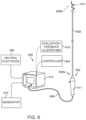
- FIG. 6 is a partially schematic illustration of a neuromodulation system configured in accordance with another embodiment of the present technology.
- FIG. 7 illustrates modulating renal nerves and/or evaluating the neuromodulation therapy with the system of FIG. 6 in accordance with an embodiment of the present technology.
- FIG. 8 is a conceptual illustration of the sympathetic nervous system (SNS) and how the brain communicates with the body via the SNS.
- SNS sympathetic nervous system
- FIG. 9 is an enlarged anatomic view of nerves innervating a left kidney to form the renal plexus surrounding the left renal artery.
- FIGS. 10 and 11 are anatomic and conceptual views, respectively, of a human body depicting neural efferent and afferent communication between the brain and kidneys.
- FIGS. 12 and 13 are anatomic views of the arterial vasculature and venous vasculature, respectively, of a human.
- Systems and methods in accordance with embodiments of the present technology are directed to obtaining measurements related to a dimension of a renal blood vessel before a neuromodulation procedure, such as a renal denervation procedure, to periprocedurally assess the likely efficacy of the neuromodulation procedure.
- the disclosed techniques can be used, for example, to assess a particular patient's likelihood of deriving a therapeutic benefit from delivered neuromodulation energy.
- a renal blood vessel may be correlated to the efficacy (e.g., a resulting drop in blood pressure, reduction in risks associated with cardiovascular disease, improvement in heart failure status, reduction in arrhythmias, etc.) of a renal denervation procedure subsequently performed in that vessel. More specifically, renal denervation may be more effective in renal blood vessels having a comparatively smaller diameter. The reasons for improved efficacy may be due to any number of factors. For example, renal nerves tend to be further from the vessel wall in larger diameter renal blood vessels and, contrariwise, closer to the vessel wall in smaller diameter renal blood vessels.
- measuring the diameter of a renal blood vessel (or a related value) before a neuromodulation procedure is performed in that particular vessel is expected to provide periprocedural information about the likely success (or lack thereof) of the neuromodulation procedure.
- a parameter of the neuromodulation procedure such as power, time, location, and/or other characteristic of energy delivered during the neuromodulation procedure—to improve the likelihood that the neuromodulation procedure will be successful.
- a neuromodulation system can include a neuromodulation catheter configured to both (i) detect one or more measurements related to a dimension of a renal blood vessel at or near a target site in the vessel and (ii) deliver therapeutic neuromodulation at the target site.
- a controller can receive the one or more measurements and accurately estimate a diameter of the renal blood vessel at or near the target site.
- an operator of the neuromodulation system and/or the controller can (i) assess the likely efficacy of delivering therapeutic neuromodulation at the target site, (ii) adjust one or more parameters of the therapeutic neuromodulation to be delivered at the target site, and/or (iii) reposition the neuromodulation catheter to a new target site.
- systems configured in accordance with the present technology are expected to improve the efficacy of a neuromodulation procedure by detecting a simple pre-neuromodulation measurement of the renal blood vessel in which the neuromodulation is performed—without the need for expensive and untimely additional measurements using separate, conventional, measurement systems.
- FIGS. 1 A- 13 Specific details of several embodiments of the present technology are described herein with reference to FIGS. 1 A- 13 . Although many of the embodiments are described with respect to devices, systems, and methods for intravascular renal neuromodulation, other applications and other embodiments in addition to those described herein are within the scope of the present technology. For example, at least some embodiments of the present technology may be useful for extravascular neuromodulation, intravascular non-renal neuromodulation, and/or use in therapies other than neuromodulation. It should be noted that other embodiments in addition to those disclosed herein are within the scope of the present technology. Further, embodiments of the present technology can have different configurations, components, and/or procedures than those shown or described herein.
- embodiments of the present technology can have configurations, components, and/or procedures in addition to those shown or described herein and that these and other embodiments can be without several of the configurations, components, and/or procedures shown or described herein without deviating from the present technology.
- distal and proximal define a position or direction with respect to a clinician or a clinician's control device (e.g., a handle of a neuromodulation catheter).
- distal and disally refer to a position distant from or in a direction away from a clinician or a clinician's control device along the length of device.
- proximal and proximally refer to a position near or in a direction toward a clinician or a clinician's control device along the length of device.
- the headings provided herein are for convenience only and should not be construed as limiting the subject matter disclosed.
- FIGS. 1 A- 1 C are partially schematic side views of a neuromodulation system 100 (“system 100 ”) configured in accordance with an embodiment of the present technology and shown in different arrangements while positioned at a target site within a blood vessel V (e.g., a renal artery) of a human patient.
- the system 100 includes a guidewire 101 (only visible in FIG. 1 A ) and a neuromodulation catheter 102 that can be advanced over the guidewire 101 to the target site within the blood vessel V.
- the neuromodulation catheter 102 can be configured for delivery to the target site via other methods (e.g., via a guide catheter, via sheath retraction, via a pull-wire, etc.).
- the neuromodulation catheter 102 is configured to perform neuromodulation therapy at the target site to, for example, ablate nerves proximate the wall of the blood vessel V. As discussed in greater detail below, the neuromodulation catheter 102 is further configured to detect one or more measurements related to a dimension (e.g., a diameter, a cross-sectional area, a circumference, a segmental volume, etc.) of the blood vessel V before neuromodulation therapy to assess the likely efficacy of subsequent neuromodulation therapy performed at the target site.
- the system 100 further includes one or more controllers 104 communicatively coupled to the neuromodulation catheter 102 via a wired or wireless communication link.
- the guidewire 101 includes an elongated member 103 having a distal portion 103 a configured to be positioned at the target site within the blood vessel V and a proximal portion (not visible) that extends outside of the patient to a handle (not shown) or other feature(s) that allow an operator to manipulate the distal portion 103 a to the desired position/orientation.
- the elongated member 103 can be sized to be slidably positioned within a lumen of the neuromodulation catheter 102 . Additionally, the elongated member 103 can have a uniform stiffness along its length, or can have a stiffness that varies along its length. In other embodiments, the elongated member 103 may comprise other suitable components and/or configurations.
- the neuromodulation catheter 102 includes an elongated shaft 106 configured to be slidably delivered over the guidewire 101 .
- the elongated shaft 106 has a distal portion 106 a configured to be intravascularly positioned at the target site within the blood vessel V and a proximal portion 106 b extending outside of the patient to a handle (not shown) or other features that allow an operator to manipulate the distal portion 106 a of the elongated shaft 106 .
- a handle not shown
- the neuromodulation catheter 102 is transformable between a first state or arrangement in which the distal portion 106 a of the elongated shaft 106 is at least generally straight and in a low-profile delivery arrangement ( FIG. 1 B ), and a second (e.g., deployed, expanded, etc.) state or arrangement in which the distal portion 106 a is transformed or otherwise expanded to a spiral/helical shape ( FIG. 1 C ).
- the neuromodulation catheter 102 includes a plurality of energy delivery elements, such as electrodes 110 spaced along the distal portion 106 a of the elongated shaft 106 and a distal tip 108 (e.g., an atraumatic tip).
- the neuromodulation catheter 102 includes four electrodes 110 (identified individually as first through fourth electrodes 110 a - 110 d , respectively). In other embodiments, however, the neuromodulation catheter 102 may include one, two, three, or more than four electrodes 110 , and/or may include different energy delivery elements.
- the electrodes 110 are configured to deliver neuromodulation energy to the target site to modulate or ablate nerves (e.g., renal nerves) proximate to the target site.
- the neuromodulation catheter 102 can include electrodes, transducers, or other elements to deliver energy to modulate nerves using other suitable neuromodulation modalities, such as pulsed electrical energy, microwave energy, optical energy, ultrasound energy (e.g., intravascularly delivered ultrasound and/or high-intensity focused ultrasound (HIFU)), direct heat energy, radiation (e.g., infrared, visible, and/or gamma radiation), and/or other suitable types of energy.
- the neuromodulation catheter 102 may be configured for cryotherapeutic treatment, and can apply cryogenic cooling to the vessel V with a refrigerant (e.g., via a balloon catheter that circulates the refrigerant).
- the dimensions (e.g., outer diameter and length) of the distal portion 106 a of the elongated shaft 106 can be selected to accommodate the vessels or other body lumens in which the distal portion 106 a is designed to be delivered.
- the axial length of the distal portion 106 a of the elongated shaft 106 may be selected to be no longer than a patient's renal artery (e.g., typically less than 7 cm), and have a diameter that accommodates the inner diameter of a typical renal artery (e.g., about 2-10 mm).
- the distal portion 106 a of the elongated shaft 106 can have other dimensions depending on the body lumen within which it is configured to be deployed. Regardless of the selected dimensions of the distal portion 106 a , in some embodiments, one or more dimensions of the distal portion 106 a are known prior to performing a neuromodulation procedure with the neuromodulation catheter 102 . As described in greater detail below, in some embodiments, the known dimensions can be used to calculate other (e.g., variable, unknown, non-constant, etc.) dimensions of the distal portion 106 a such as a diameter of the distal portion 106 a in the spiral/helical second state.
- other dimensions of the distal portion 106 a such as a diameter of the distal portion 106 a in the spiral/helical second state.
- the distal portion 106 a of the elongated shaft 106 can have other suitable shapes (e.g., semi-circular, curved, straight, etc.), and/or the neuromodulation catheter 102 can include multiple support members configured to carry one or more electrodes 110 .
- the distal portion 106 a of the elongated shaft 106 may also be designed to apply a desired outward radial force to a vessel when expanded to the spiral/helical second state to place one or more of the electrodes 110 in contact with the vessel wall.
- the system 100 includes a console (not shown).
- the controller 104 may be separated from the console or may be integrated with the console.
- the controller 104 can be configured to initiate, terminate, and/or adjust operation of one or more components (e.g., the electrodes 110 ) of the neuromodulation catheter 102 directly and/or via the console.
- the controller 104 may be configured to continuously or intermittently monitor the impedance between each of the electrodes 110 .
- the console can be configured to communicate with the neuromodulation catheter 102 via a wireless and/or wired communication link.
- the console can include an access port for receiving a wired connection to the neuromodulation catheter 102 .
- the console can be configured to control, monitor, supply, and/or otherwise support operation of the neuromodulation catheter 102 .
- the console can further be configured to generate a selected form and/or magnitude of energy for delivery to tissue at the target site via the electrodes 110 , and therefore the console may have different configurations depending on the treatment modality of the neuromodulation catheter 102 .
- the console can include an energy generator (not shown) configured to generate RF energy.
- the console can be configured to provide feedback to an operator before, during, and/or after a neuromodulation procedure such as, for example, a determined diameter of the blood vessel V and/or a likely efficacy of a neuromodulation procedure performed at the target site.
- the neuromodulation catheter 102 shown in FIGS. 1 A- 1 C has a spiral/helically-shaped configuration
- the neuromodulation catheter 102 can have other suitable shapes, sizes, and/or configurations.
- Other suitable devices and technologies are described in, for example, U.S. Pat. Nos. 8,777,942; 9,084,610; 9,060,755; 8,998,894; PCT Application No. PCT/US2011/057754, filed Oct. 25, 2011; and U.S. Pat. No. 8,888,773. All of the foregoing applications are incorporated herein by reference in their entireties.
- Another non-limiting example of a device includes the Symplicity SpyralTM multielectrode RF ablation catheter.
- the system 100 of the present technology includes at least one measuring element configured to detect (e.g., obtain, make, etc.) one or more measurements related to a dimension of a blood vessel before delivery of neuromodulation energy.
- the measuring element can comprise one or more of the electrodes 110 at the distal portion 106 a of the elongated shaft 106 of the neuromodulation catheter 102 .
- the system 100 can be configured to measure impedance between two or more of the electrodes 110 before neuromodulation energy is delivered via the electrodes 110 .
- the detected impedance measurements can be transmitted to the controller 104 and/or another device external to the patient.
- the controller 104 can be configured to receive and store the detected impedance measurements and determine a dimension (e.g., a diameter) of the blood vessel V based, at least in part, on one or more of the detected impedance measurements.
- signals may be sent between one or more pairs of the electrodes 110 to measure impedance between the electrodes 110 .
- the impedance between combinations of two different electrodes may be measured.
- signals may be sent between (i) the first electrode 110 a and the second electrode 110 b , (ii) the first electrode 110 a and the third electrode 110 c , (iii) the first electrode 110 a and the fourth electrode 110 d , (iv) the second electrode 110 b and the third electrode 110 c , (v) the second electrode 110 b and the fourth electrode 110 d , and (vi) the third electrode 110 c and the fourth electrode 110 d .
- impedance measurements may be obtained for less than every combination of pairs of the electrodes 110 (e.g., a single impedance measurement between the first electrode 110 a and the fourth electrode 110 d ).
- the obtained impedance measurements may be stored at the controller 104 and processed to determine a dimension of the blood vessel V near the electrodes 110 (e.g., near the target site).
- the dimension of the blood vessel V can be estimated using the cylindrical equation:
- the cylindrical equation (1) provides that the cross-sectional area A of a cylinder of relatively constant diameter filled with a material of constant resistivity p is proportional to the impedance R measured over a distance L.
- the resistivity p of the blood in the blood vessel V may be directly measured or estimated by applying one or more pre-determined correction coefficients to the cylindrical equation (1). Accordingly, based on a known longitudinal distance L between selected electrodes 110 , the cross-sectional area A (and hence a diameter of the blood vessel V) can be estimated.
- impedance measurements and/or related values can be averaged and/or otherwise combined to provide a relatively accurate estimate of the diameter or another dimension (e.g., circumference) of the blood vessel V.
- impedance measurements detected by the electrodes 110 can be used to determine an actual (e.g., absolute) dimension of the blood vessel V while, in other embodiments, impedance measurements can be compared to a baseline measurement to determine a relative difference in the dimension of the blood vessel V (e.g., from a first location to a second location within the vessel).
- One advantage of using the electrodes 110 to detect a measurement related to a dimension of the blood vessel V is that no physical modifications need to be made to the neuromodulation catheter 102 . That is, the same electrodes 110 that deliver neuromodulation energy may be used to determine the diameter of the target blood vessel V if the resistivity of the blood in the blood vessel V is known or can be estimated.
- the measuring element of the system 100 may comprise a separate component positioned at the distal portion of the neuromodulation catheter 102 .
- FIG. 2 is a partially schematic side view of the neuromodulation system shown in FIG. 1 C (e.g., in the second state) and including a distance sensor (e.g., a proximity sensor).
- the distance sensor can be configured to detect a distance between a first portion of the neuromodulation catheter 102 , such as the distal tip 108 , and a second, more proximal portion of the neuromodulation catheter 102 .
- the distance sensor includes a first sensing component 223 on the distal tip 108 and a second sensing component 224 on the distal portion of the neuromodulation catheter 102 and positioned proximal to the fourth electrode 110 d .
- the distance sensor is a capacitive distance sensor, a Hall effect distance sensor, a piezoelectric distance sensor, a magnetic distance sensor, and/or another type of distance sensor configured to measure a distance between the first and second sensing components 223 , 224 (“sensing components 223 , 224 ”).
- the detected distance between the sensing components 223 , 224 can be used to determine a dimension (e.g., diameter) of the blood vessel V based on known dimensions of the neuromodulation catheter 102 .
- the detected distance between the sensing components 223 , 224 can be used to determine the diameter of the blood vessel V since, for example, the longitudinal distance between the sensing components will vary in conformance with the diameter of the blood vessel V (e.g., the longitudinal distance will be greater when the blood vessel V has a smaller diameter and the distal portion of the neuromodulation catheter 102 is not fully radially expanded). More specifically, in some embodiments, the longitudinal distance between the sensing components 223 , 224 can be used to determine an angle of rotation of the distal portion of the neuromodulation catheter 102 when the neuromodulation catheter 102 is in the second (expanded) state.
- the angle of rotation can be used to calculate the diameter of the distal portion of the neuromodulation catheter 102 that apposes the inner wall of the blood vessel V. Accordingly, the determined diameter of the distal portion of the neuromodulation catheter 102 can be used to estimate the diameter of the blood vessel V.
- the sensing components 223 , 224 may be positioned differently with respect to the neuromodulation catheter 102 .
- the second sensing component 224 may be positioned further distally or proximally with respect to the neuromodulation catheter 102 (e.g., adjacent to one of the electrodes 110 ) and/or the first sensing component 223 may be positioned proximal to the distal tip 108 .
- the sensing components 223 , 224 are positioned on the exterior of the neuromodulation catheter 102 . In other embodiments, however, the sensing components 223 , 224 may be positioned fully within (i.e., internal to) or partially within the neuromodulation catheter 102 .
- the system 100 can include more than one distance sensor and/or one or more distance measurements may be averaged or otherwise combined to estimate a dimension of the blood vessel V.
- the sensing components 223 , 224 can be coupled to the controller 104 and/or other components of the system 100 via one or more wires extending through the neuromodulation catheter 102 , or the sensing components 223 , 224 can be wirelessly coupled to the controller 104 and/or other components of the system 100 .
- FIG. 3 illustrates another embodiment of a measuring element positioned at the distal portion of the neuromodulation catheter 102 .
- FIG. 3 is a front view of the distal portion of the neuromodulation catheter 102 in the second state shown in FIG. 1 C , and looking down a longitudinal axis L (shown in FIG. 1 C ) of the blood vessel V in the proximal direction.
- the system 100 can include a distance sensor 322 positioned at the distal tip 108 of the neuromodulation catheter. In other embodiments, the distance sensor 322 may be positioned elsewhere on the distal portion of the neuromodulation catheter 102 .
- the distance sensor 322 can be an odometer-type sensor (e.g., a wheel, track ball, other rotatable component, etc.) configured to measure a circumference (or other dimension) of the blood vessel V as the distal portion of the neuromodulation catheter 102 is rotated within the blood vessel V.
- the system 100 can be configured to automatically (e.g., via a motor external to the patient) rotate the distal portion of the neuromodulation catheter 102 in the direction of arrow C such that the distance sensor 322 passes completely around a circumference of the blood vessel V (e.g., one full rotation).
- the detected circumference of the blood vessel V can be easily used to determine the diameter of the blood vessel V.
- the measuring element of the system 100 can comprise other components suitable for detecting a measurement related to a dimension of the blood vessel V.
- a balloon or other inflatable component can be positioned at least partially at the distal portion of the neuromodulation catheter 102 .
- the balloon can be (i) positioned on the exterior of the neuromodulation catheter 102 , (ii) have at least one fixed dimension (e.g., a fixed longitudinal length), and (iii) can be inflated with a measured (e.g., known) volume or inflation pressure.
- a measured volume or inflation pressure e.g., known
- the balloon may have one or more electrodes configured to detect when the balloon contacts the inner wall of the blood vessel V.
- the electrodes on the balloon may also be configured to deliver neuromodulation energy.
- a pressure inside the balloon can be measured and used to detect when the balloon contacts the inner wall of the blood vessel V. For example, a sudden increase in the pressure of the balloon could indicate that the balloon is in apposition with the inner wall of the blood vessel V.
- the measuring element of the system 100 can comprise one or more wires or other electrical elements positioned at the distal portion of the neuromodulation catheter 102 and having a variable resistance that changes based on how much the electrical elements are bent.
- the resistance of the electrical elements can be used to determine (e.g., can be correlated to) the diameter of the distal portion of the neuromodulation catheter 102 .
- the change in resistance can be directly correlated to the curvature of the neuromodulation catheter 102 , which can be used to determine the diameter of the blood vessel V, as set forth in detail above.
- the diameter of the blood vessel V can be estimated based on the resistance of the electrical elements.
- the measuring element 100 can comprise standard imaging systems and/or components used in well-known imaging techniques such as, for example, fluoroscopy, magnetic resonance imaging (MRI), intravascular ultrasound (IVUS), etc.
- imaging techniques such as, for example, fluoroscopy, magnetic resonance imaging (MRI), intravascular ultrasound (IVUS), etc.
- Each of the embodiments described are expected to facilitate measurement(s) related to a dimension of the blood vessel V via the neuromodulation catheter 102 . Such measurements can be used to determine or estimate the diameter of the blood vessel V near a target site in the blood vessel V and, correlatively, the likely efficacy of neuromodulation therapy subsequently performed at the target site.
- embodiments of the present technology are expected to quickly and cheaply determine the likely efficacy of neuromodulation therapy since the same device may be used to both measure a dimension of a target blood vessel and deliver neuromodulation energy to target nerves adjacent that same vessel.
- the present technology is also expected to improve the efficacy of neuromodulation therapy by permitting (i) customization of a neuromodulation energy delivery profile and/or (ii) improved target site selection.
- FIG. 4 is a flow diagram of a method or process 400 for evaluating the likely efficacy of neuromodulation therapy and/or modifying one or more parameters of neuromodulation therapy in accordance with embodiments of the present technology.
- the method 400 can be implemented using the system 100 described above with reference to FIGS. 1 A- 3 and/or using other suitable systems.
- the neuromodulation catheter 102 and/or the controller 104 can be used to perform the various steps of the method 400 . Accordingly, for sake of illustration, some features of the method 400 will be described in the context of the embodiments shown in FIGS. 1 A- 3 .
- the method 400 includes positioning the neuromodulation catheter 102 at a target site within the blood vessel V of the human patient.
- positioning the neuromodulation catheter 102 includes (i) positioning the guidewire 101 along a portion of the blood vessel V proximate the target site ( FIG. 1 A ), (ii) advancing the neuromodulation catheter 102 over the guidewire 101 to the target site ( FIG. 1 B ), and (iii) transforming or otherwise expanding the distal portion of the neuromodulation catheter 102 to the spiral/helical shape in which the electrodes 110 contact the wall of the blood vessel V ( FIG. 1 C ).
- the method 400 includes obtaining one or more measurements related to or corresponding to a dimension (e.g., a diameter, a circumference, etc.) of the blood vessel V near the target site by, for example, using the measuring element of the neuromodulation catheter 102 .
- the measurements can include one or more of the following: impedance measurement(s) between two or more of the electrodes 110 ; a distance between spaced apart portions of the neuromodulation catheter 102 ; a distance between two or more of the electrodes 110 ; an angle of rotation of the distal portion of the neuromodulation catheter 102 ; a volume of an inflatable balloon; etc.
- the controller 104 can be configured to (i) control the electrodes 110 to generate and detect one or more signals that propagate through the blood vessel V and (ii) determine one or more impedance values between two or more of electrodes 110 that are related to the dimension of the blood vessel V.
- the controller 104 can be configured to control the distance sensor to obtain a distance measurement related to the dimension of the blood vessel V.
- the one or more measurements can be a single measurement or a composite or average of several different measurements.
- the measurements can be an average of several measurements taken over a period of seconds (e.g., about 0.5 second, about 1 second, about 2 seconds, less than about 5 seconds, etc.) to account for changes in the dimension of the blood vessel V during the cardiac cycle (e.g., to account for differing vessel diameters during systole and diastole).
- the obtained measurements can be communicated to and stored in the memory of the controller 104 and/or another component of the system 100 .
- the method 400 includes determining a diameter of the blood vessel V at or near the target site based on the one or more measurements obtained via the measuring element of the neuromodulation catheter 102 .
- the controller 104 or another component of the system 100 can process the one or more measurements to determine the diameter of the blood vessel V (e.g., based on known properties of the neuromodulation catheter 102 ).
- the controller 104 and/or an operator of the system 100 can assess the likely efficacy of performing neuromodulation therapy at the target site by, for example, correlating the diameter to expected results of neuromodulation therapy (e.g., an expected drop in blood pressure at a certain point after a renal denervation procedure).
- the controller 104 and/or the operator may determine that neuromodulation therapy is more likely to be effective.
- the baseline value may be a diameter measurement of a different location (e.g., a different target site) within the same blood vessel V, or a diameter measurement of a different blood vessel within the patient.
- the baseline measurement can be an average vessel size (e.g., for a patient with similar characteristics) or another value not specific to the patient.
- the method 400 can include repositioning the neuromodulation catheter 102 to, for example, a different target site within the blood vessel V.
- the measuring element of the neuromodulation catheter 102 can be used to estimate the diameter of the blood vessel V at multiple locations within the blood vessel V (e.g., as the neuromodulation catheter 102 is moved within the vessel V) to determine a smallest diameter section of the blood vessel V.
- the estimated diameter can be displayed to an operator of the system 100 (e.g., on the console in real-time or near-real time), and the operator can view the display and maneuver the neuromodulation catheter 102 within the patient in order to identify the smallest diameter section of the blood vessel V.
- the method 400 can include adjusting one or more parameters of neuromodulation therapy to be delivered at the target site.
- FIG. 5 is a graph illustrating a suitable neuromodulation energy delivery profile in accordance with embodiments of the present technology.
- the neuromodulation therapy may include an initial power ramp stage in which the power of delivered neuromodulation energy is ramped to a power P 1 over a time T 1 .
- the power P 1 can then be sustained for a time T 2 before a first step ramp stage in which the power of delivered neuromodulation energy is ramped to a power P 2 over a time T 3 .
- the power P 2 can then be sustained for a time T 4 before a second step ramp stage in which the power of delivered neuromodulation energy is ramped to a power P 5 over a time T 5 .
- the power can then be (i) stepped down to a power P 4 and sustained for a time T 6 and then (ii) stepped down to a power P 3 and sustained for a time T 7 .
- the neuromodulation energy delivery profile may have other configurations and/or parameters.
- the powers P 1 -P 5 and/or the delivery times T 1 -T 7 are standard or baseline values that can be adjusted based on the estimated diameter of the vessel, either manually by an operator of the system 100 and/or automatically by the controller 104 . That is, the energy delivery profile can be modified to target renal nerves having a varying depth from the wall of the blood vessel V, as opposed to conventional systems in which an energy delivery profile targets a uniform depth of ablation via a fixed power output (e.g., a fixed maximum sustained power output).
- a fixed power output e.g., a fixed maximum sustained power output
- the delivery time e.g., any or all of T 1 -T 7
- the amount of power delivered e.g., any or all of P 1 -P 5
- the present technology can enable a more uniform neuromodulation treatment of targeted renal nerves—regardless of the diameter of the renal vessel.
- a menu on the console of the system 100 can include two or more selectable options of vessel diameter that each provide a different combination of neuromodulation parameters.
- the options may include, for example, a main vessel option (e.g., for a vessel having a relatively larger diameter) and a branch option (e.g., for a vessel having a relatively smaller diameter). Such an embodiment is based on the assumption that branching vessels have a relatively smaller diameter than a corresponding main vessel.
- the menu can include options that are more specific such as, for example, a branch vessel option having more vasculature around it (e.g., increasing heat transfer away from the target site) and a branch vessel option having less vasculature around it.
- the method 400 may determine that no parameters of the neuromodulation energy delivery profile need to be adjusted, and the method 400 can proceed directly to block 412 .
- the method 400 proceeds to block 412 and neuromodulation energy is delivered at the target site in the blood vessel V to ablate nerves proximate to the wall of the blood vessel V.
- the method 400 can include applying RF energy (e.g., via the electrodes 110 ), pulsed electrical energy, microwave energy, optical energy, ultrasound energy (e.g., intravascularly delivered ultrasound and/or HIFU), direct heat energy, radiation, cryogenic cooling, chemical-based treatment, and/or another suitable type of neuromodulation energy.
- the system 100 can facilitate efficient and effective neuromodulation treatments.
- FIG. 6 is a partially schematic illustration of a therapeutic system 600 (“system 600 ”) configured in accordance with an embodiment of the present technology.
- the system 600 can include various features similar to the neuromodulation system 100 described above with reference to FIGS. 1 A- 3 .
- the system 600 can be used to implement any of the methods described herein.
- the system 600 includes a neuromodulation catheter 602 , a console 614 , and a cable 606 extending therebetween.
- the neuromodulation catheter 602 can include an elongated shaft 608 having a proximal portion 608 b , a distal portion 608 a , and a handle 611 operably connected to the elongated shaft 608 at the proximal portion 608 b .
- the elongated shaft 608 can be 2, 3, 4, 5, 6, or 7 French or another suitable size.
- one or more electrodes 610 can be spaced along the distal portion 608 a of the elongated shaft 608 .
- the electrodes 610 can be configured to apply electrical stimuli (e.g., radio frequency (RF) energy) to target sites at or proximate to vessels within a patient, temporarily stun nerves, deliver neuromodulation energy to target sites, and/or detect vessel impedance.
- electrical stimuli e.g., radio frequency (RF) energy
- certain electrodes 610 can be dedicated to applying stimuli and/or detecting impedance
- the neuromodulation catheter 602 can include other types of therapeutic elements that provide neuromodulation therapy using various modalities, such cryotherapeutic cooling, ultrasound energy, etc.
- the console 614 can be configured to control, monitor, supply, and/or otherwise support operation of the neuromodulation catheter 602 .
- the console 614 can be configured to provide feedback to an operator before, during, and/or after a treatment procedure via an evaluation/feedback algorithm 616 .
- the console 614 can further be configured to generate a selected form and/or magnitude of energy for delivery to tissue at the treatment site via the electrodes 610 , and therefore the console 614 may have different configurations depending on the treatment modality of the neuromodulation catheter 602 .
- the console 614 can include an energy generator 670 (shown schematically) configured to generate RF energy (e.g., monopolar and/or bipolar RF energy), pulsed energy, microwave energy, optical energy, ultrasound energy (e.g., intravascularly delivered ultrasound and/or high-intensity focused ultrasound (HIFU)), direct heat energy, radiation (e.g., infrared, visible, and/or gamma radiation), and/or another suitable type of energy.
- RF energy e.g., monopolar and/or bipolar RF energy
- pulsed energy e.g., microwave energy, optical energy, ultrasound energy (e.g., intravascularly delivered ultrasound and/or high-intensity focused ultrasound (HIFU)
- ultrasound energy e.g., intravascularly delivered ultrasound and/or high-intensity focused ultrasound (HIFU)
- HIFU high-intensity focused ultrasound
- the console 614 can also include evaluation/feedback algorithms 616 for controlling the electrodes 610 .
- the energy generator 670 can be configured to deliver a monopolar electric field via one or more of the electrodes 610 .
- a neutral or dispersive electrode 660 may be electrically coupled to the energy generator 670 and attached to the exterior of the patient.
- the console 614 can include a refrigerant reservoir (not shown) and can be configured to supply the neuromodulation catheter 602 with refrigerant.
- the console 614 can include a chemical reservoir (not shown) and can be configured to supply the neuromodulation catheter 602 with one or more chemicals.
- the system 600 can further include a controller 604 communicatively coupled to the neuromodulation catheter 602 .
- the controller 604 can be configured to initiate, terminate, and/or adjust operation of one or more components (e.g., the electrodes 610 ) of the neuromodulation catheter 602 directly and/or via the console 614 and/or via a wired or wireless communication link.
- the system 600 can include multiple controllers.
- the neuromodulation catheter 602 can be communicatively coupled to a single controller 604 .
- the controller(s) 604 can be integrated with the console 614 or the handle 611 positioned outside the patient and used to operate the system 600 .
- the controller 604 can be omitted or have other suitable locations (e.g., within the handle 611 , along the cable 606 , etc.).
- the controller 604 can include computer-implemented instructions to initiate, terminate, and/or adjust operation of one or more components of the neuromodulation catheter 602 directly and/or via another aspect of the system (e.g., the console 614 and/or handle 611 ).
- the controller 604 can further provide instructions to the neuromodulation catheter 602 to apply neuromodulatory energy to the treatment site (e.g., RF energy via the electrodes 610 ).
- the controller 604 can be configured to execute an automated control algorithm and/or to receive control instructions from an operator.
- the controller 604 can include or be linked to the evaluation/feedback algorithm 616 that can provide feedback to an operator before, during, and/or after a treatment procedure via a console, monitor, and/or other user interface.
- FIG. 7 illustrates modulating renal nerves in accordance with an embodiment of the system 600 .
- the neuromodulation catheter 602 provides access to the renal plexus RP through an intravascular path P, such as a percutaneous access site in the femoral (illustrated), brachial, radial, or axillary artery to a targeted treatment site within a respective renal artery RA.
- an intravascular path P such as a percutaneous access site in the femoral (illustrated), brachial, radial, or axillary artery to a targeted treatment site within a respective renal artery RA.
- the distal portion 608 a of the elongated shaft 608 is delivered intravascularly to the treatment site using a guidewire 601 in an OTW technique.
- the distal end of the neuromodulation catheter 602 may define a passageway for receiving the guidewire 601 for delivery of the neuromodulation catheter 602 using either OTW or RX techniques.
- the guidewire 601 can be at least partially withdrawn or removed, and the distal portion of the neuromodulation catheter 602 can transform or otherwise be moved to a deployed arrangement for recording neural activity and/or delivering energy at the treatment site.
- the neuromodulation catheter 602 may be delivered to the treatment site within a guide sheath (not shown) with or without using the guidewire 601 .
- the guide sheath When the neuromodulation catheter 602 is at the target site, the guide sheath may be at least partially withdrawn or retracted and the distal portion of the neuromodulation catheter 602 can be transformed into the deployed arrangement.
- the elongated shaft 608 may be steerable itself such that the neuromodulation catheter 602 may be delivered to the treatment site without the aid of the guidewire 601 and/or guide sheath.
- Image guidance e.g., computed tomography (CT), fluoroscopy, intravascular ultrasound (IVUS), optical coherence tomography (OCT), intracardiac echocardiography (ICE), or another suitable guidance modality, or combinations thereof, may be used to aid the clinician's positioning and manipulation of the neuromodulation catheter 602 .
- a fluoroscopy system e.g., including a flat-panel detector, x-ray, or c-arm
- the treatment site can be determined using IVUS, OCT, and/or other suitable image mapping modalities that can correlate the target treatment site with an identifiable anatomical structure (e.g., a spinal feature) and/or a radiopaque ruler (e.g., positioned under or on the patient) before delivering the neuromodulation catheter 602 .
- image guidance components e.g., IVUS, OCT
- image guidance components e.g., IVUS or OCT
- IVUS intravascular coronary intervention device
- OCT optical coherence tomography
- Energy from the electrodes 610 ( FIG. 6 ) and/or other energy delivery elements may then be applied to target tissue to induce one or more desired neuromodulating effects on localized regions of the renal artery RA and adjacent regions of the renal plexus RP, which lay intimately within, adjacent to, or in close proximity to the adventitia of the renal artery RA.
- the purposeful application of the energy may achieve neuromodulation along all or at least a portion of the renal plexus RP.
- the neuromodulating effects are generally a function of, at least in part, power, time, contact between the energy delivery elements and the vessel wall, and blood flow through the vessel.
- the neuromodulating effects may include denervation, thermal ablation, and/or non-ablative thermal alteration or damage (e.g., via sustained heating and/or resistive heating).
- Desired thermal heating effects may include raising the temperature of target neural fibers above a desired threshold to achieve non-ablative thermal alteration, or above a higher temperature to achieve ablative thermal alteration.
- the target temperature may be above body temperature (e.g., approximately 37° C.) but less than about 45° C. for non-ablative thermal alteration, or the target temperature may be about 45° C. or higher for the ablative thermal alteration.
- Desired non-thermal neuromodulation effects may include altering the electrical signals transmitted in a nerve.
- Renal neuromodulation is the partial or complete incapacitation or other effective disruption of nerves of the kidneys (e.g., nerves terminating in the kidneys or in structures closely associated with the kidneys).
- renal neuromodulation can include inhibiting, reducing, and/or blocking neural communication along neural fibers (e.g., efferent and/or afferent neural fibers) of the kidneys.
- Such incapacitation can be long-term (e.g., permanent or for periods of months, years, or decades) or short-term (e.g., for periods of minutes, hours, days, or weeks).
- Renal neuromodulation is expected to contribute to the systemic reduction of sympathetic tone or drive and/or to benefit at least some specific organs and/or other bodily structures innervated by sympathetic nerves. Accordingly, renal neuromodulation is expected to be useful in treating clinical conditions associated with systemic sympathetic over activity or hyperactivity, particularly conditions associated with central sympathetic overstimulation. For example, renal neuromodulation is expected to efficaciously treat hypertension, heart failure, acute myocardial infarction, metabolic syndrome, insulin resistance, diabetes, left ventricular hypertrophy, chronic and end stage renal disease, inappropriate fluid retention in heart failure, cardio-renal syndrome, polycystic kidney disease, polycystic ovary syndrome, osteoporosis, erectile dysfunction, and sudden death, among other conditions.
- Renal neuromodulation can be electrically-induced, thermally-induced, chemically-induced, or induced in another suitable manner or combination of manners at one or more suitable treatment sites during a treatment procedure.
- the treatment site can be within or otherwise proximate to a renal lumen (e.g., a renal artery, a ureter, a renal pelvis, a major renal calyx, a minor renal calyx, or another suitable structure), and the treated tissue can include tissue at least proximate to a wall of the renal lumen.
- a treatment procedure can include modulating nerves in the renal plexus, which lay intimately within or adjacent to the adventitia of the renal artery.
- Renal neuromodulation can include a cryotherapeutic treatment modality alone or in combination with another treatment modality.
- Cryotherapeutic treatment can include cooling tissue at a treatment site in a manner that modulates neural function.
- sufficiently cooling at least a portion of a sympathetic renal nerve can slow or potentially block conduction of neural signals to produce a prolonged or permanent reduction in renal sympathetic activity.
- This effect can occur as a result of cryotherapeutic tissue damage, which can include, for example, direct cell injury (e.g., necrosis), vascular or luminal injury (e.g., starving cells from nutrients by damaging supplying blood vessels), and/or sublethal hypothermia with subsequent apoptosis.
- Exposure to cryotherapeutic cooling can cause acute cell death (e.g., immediately after exposure) and/or delayed cell death (e.g., during tissue thawing and subsequent hyperperfusion).
- Neuromodulation using a cryotherapeutic treatment in accordance with embodiments of the present technology can include cooling a structure proximate an inner surface of a body lumen wall such that tissue is effectively cooled to a depth where sympathetic renal nerves reside.
- a cooling assembly of a cryotherapeutic device can be cooled to the extent that it causes therapeutically-effective, cryogenic renal neuromodulation.
- a cryotherapeutic treatment modality can include cooling that is not configured to cause neuromodulation.
- the cooling can be at or above cryogenic temperatures and can be used to control neuromodulation via another treatment modality (e.g., to protect tissue from neuromodulating energy).
- Renal neuromodulation can include an electrode-based or transducer-based treatment modality alone or in combination with another treatment modality.
- Electrode-based or transducer-based treatment can include delivering electricity and/or another form of energy to tissue at a treatment location to stimulate and/or heat the tissue in a manner that modulates neural function. For example, sufficiently stimulating and/or heating at least a portion of a sympathetic renal nerve can slow or potentially block conduction of neural signals to produce a prolonged or permanent reduction in renal sympathetic activity.
- a variety of suitable types of energy can be used to stimulate and/or heat tissue at a treatment location.
- neuromodulation in accordance with embodiments of the present technology can include delivering RF energy, pulsed energy, microwave energy, optical energy, focused ultrasound energy (e.g., HIFU energy), or another suitable type of energy alone or in combination.
- An electrode or transducer used to deliver this energy can be used alone or with other electrodes or transducers in a multi-electrode or multi-transducer array.
- the energy can be applied from within the body (e.g., within the vasculature or other body lumens in a catheter-based approach) and/or from outside the body (e.g., via an applicator positioned outside the body).
- energy can be used to reduce damage to non-targeted tissue when targeted tissue adjacent to the non-targeted tissue is subjected to neuromodulating cooling.
- Focused ultrasound is an example of a transducer-based treatment modality that can be delivered from outside the body.
- Focused ultrasound treatment can be performed in close association with imaging (e.g., magnetic resonance, computed tomography, fluoroscopy, optical coherence tomography, or another suitable imaging modality).
- imaging can be used to identify an anatomical position of a treatment location (e.g., as a set of coordinates relative to a reference point). The coordinates can then entered into a focused ultrasound device configured to change the power, angle, phase, or other suitable parameters to generate an ultrasound focal zone at the location corresponding to the coordinates.
- the focal zone can be small enough to localize therapeutically-effective heating at the treatment location while partially or fully avoiding potentially harmful disruption of nearby structures.
- the ultrasound device can be configured to pass ultrasound energy through a lens, and/or the ultrasound energy can be generated by a curved transducer or by multiple transducers in a phased array (curved or straight).
- Heating effects of electrode-based or transducer-based treatment can include ablation and/or non-ablative alteration or damage (e.g., via sustained heating and/or resistive heating).
- a treatment procedure can include raising the temperature of target neural fibers to a target temperature above a first threshold to achieve non-ablative alteration, or above a second, higher threshold to achieve ablation.
- the target temperature can be higher than about body temperature (e.g., about 37° C.) but less than about 45° C. for non-ablative alteration, and the target temperature can be higher than about 45° C. for ablation.
- Heating tissue to a temperature between about body temperature and about 45° C.
- Non-ablative alteration for example, via moderate heating of target neural fibers or of vascular or luminal structures that perfuse the target neural fibers.
- the target neural fibers can be denied perfusion resulting in necrosis of the neural tissue.
- Heating tissue to a target temperature higher than about 45° C. e.g., higher than about 60° C.
- Renal neuromodulation can include a chemical-based treatment modality alone or in combination with another treatment modality.
- Neuromodulation using chemical-based treatment can include delivering one or more chemicals (e.g., drugs or other agents) to tissue at a treatment location in a manner that modulates neural function.
- the chemical for example, can be selected to affect the treatment location generally or to selectively affect some structures at the treatment location over other structures.
- the chemical for example, can be guanethidine, ethanol, phenol, a neurotoxin, or another suitable agent selected to alter, damage, or disrupt nerves.
- a variety of suitable techniques can be used to deliver chemicals to tissue at a treatment location.
- chemicals can be delivered via one or more needles originating outside the body or within the vasculature or other body lumens.
- a catheter can be used to intravascularly position a therapeutic element including a plurality of needles (e.g., micro-needles) that can be retracted or otherwise blocked prior to deployment.
- a chemical can be introduced into tissue at a treatment location via simple diffusion through a body lumen wall, electrophoresis, or another suitable mechanism. Similar techniques can be used to introduce chemicals that are not configured to cause neuromodulation, but rather to facilitate neuromodulation via another treatment modality.
- the sympathetic nervous system is a branch of the autonomic nervous system along with the enteric nervous system and parasympathetic nervous system. It is always active at a basal level (called sympathetic tone) and becomes more active during times of stress.
- the sympathetic nervous system operates through a series of interconnected neurons. Sympathetic neurons are frequently considered part of the peripheral nervous system (PNS), although many lie within the central nervous system (CNS).
- Sympathetic neurons of the spinal cord (which is part of the CNS) communicate with peripheral sympathetic neurons via a series of sympathetic ganglia. Within the ganglia, spinal cord sympathetic neurons join peripheral sympathetic neurons through synapses. Spinal cord sympathetic neurons are therefore called presynaptic (or preganglionic) neurons, while peripheral sympathetic neurons are called postsynaptic (or postganglionic) neurons.
- preganglionic sympathetic neurons release acetylcholine, a chemical messenger that binds and activates nicotinic acetylcholine receptors on postganglionic neurons.
- postganglionic neurons principally release noradrenaline (norepinephrine). Prolonged activation may elicit the release of adrenaline from the adrenal medulla.
- norepinephrine and epinephrine bind adrenergic receptors on peripheral tissues. Binding to adrenergic receptors causes a neuronal and hormonal response. The physiologic manifestations include pupil dilation, increased heart rate, occasional vomiting, and increased blood pressure. Increased sweating is also seen due to binding of cholinergic receptors of the sweat glands.
- the sympathetic nervous system is responsible for up- and down-regulating many homeostatic mechanisms in living organisms. Fibers from the SNS innervate tissues in almost every organ system, providing at least some regulatory function to physiological features as diverse as pupil diameter, gut motility, and urinary output. This response is also known as sympatho-adrenal response of the body, as the preganglionic sympathetic fibers that end in the adrenal medulla (but also all other sympathetic fibers) secrete acetylcholine, which activates the secretion of adrenaline (epinephrine) and to a lesser extent noradrenaline (norepinephrine). Therefore, this response that acts primarily on the cardiovascular system is mediated directly via impulses transmitted through the sympathetic nervous system and indirectly via catecholamines secreted from the adrenal medulla.
- the SNS provides a network of nerves that allows the brain to communicate with the body.
- Sympathetic nerves originate inside the vertebral column, toward the middle of the spinal cord in the intermediolateral cell column (or lateral horn), beginning at the first thoracic segment of the spinal cord and are thought to extend to the second or third lumbar segments. Because its cells begin in the thoracic and lumbar regions of the spinal cord, the SNS is said to have a thoracolumbar outflow. Axons of these nerves leave the spinal cord through the anterior rootlet/root. They pass near the spinal (sensory) ganglion, where they enter the anterior rami of the spinal nerves.
- the axons In order to reach the target organs and glands, the axons should travel long distances in the body, and, to accomplish this, many axons relay their message to a second cell through synaptic transmission. The ends of the axons link across a space, the synapse, to the dendrites of the second cell. The first cell (the presynaptic cell) sends a neurotransmitter across the synaptic cleft where it activates the second cell (the postsynaptic cell). The message is then carried to the final destination.
- ganglia In the SNS and other components of the peripheral nervous system, these synapses are made at sites called ganglia, discussed above.
- the cell that sends its fiber is called a preganglionic cell, while the cell whose fiber leaves the ganglion is called a postganglionic cell.
- the preganglionic cells of the SNS are located between the first thoracic (T 1 ) segment and third lumbar (L 3 ) segments of the spinal cord.
- Postganglionic cells have their cell bodies in the ganglia and send their axons to target organs or glands.
- the ganglia include not just the sympathetic trunks but also the cervical ganglia (superior, middle and inferior), which sends sympathetic nerve fibers to the head and thorax organs, and the celiac and mesenteric ganglia (which send sympathetic fibers to the gut).
- the kidney is innervated by the renal plexus (RP), which is intimately associated with the renal artery.
- the renal plexus (RP) is an autonomic plexus that surrounds the renal artery and is embedded within the adventitia of the renal artery.
- the renal plexus (RP) extends along the renal artery until it arrives at the substance of the kidney. Fibers contributing to the renal plexus (RP) arise from the celiac ganglion, the superior mesenteric ganglion, the aorticorenal ganglion and the aortic plexus.
- the renal plexus (RP) also referred to as the renal nerve, is predominantly comprised of sympathetic components. There is no (or at least very minimal) parasympathetic innervation of the kidney.
- Preganglionic neuronal cell bodies are located in the intermediolateral cell column of the spinal cord. Preganglionic axons pass through the paravertebral ganglia (they do not synapse) to become the lesser splanchnic nerve, the least splanchnic nerve, first lumbar splanchnic nerve, second lumbar splanchnic nerve, and travel to the celiac ganglion, the superior mesenteric ganglion, and the aorticorenal ganglion. Postganglionic neuronal cell bodies exit the celiac ganglion, the superior mesenteric ganglion, and the aorticorenal ganglion to the renal plexus (RP) and are distributed to the renal vasculature.
- RP renal plexus
- Efferent messages may trigger changes in different parts of the body simultaneously.
- the sympathetic nervous system may accelerate heart rate; widen bronchial passages; decrease motility (movement) of the large intestine; constrict blood vessels; increase peristalsis in the esophagus; cause pupil dilation, piloerection (goose bumps) and perspiration (sweating); and raise blood pressure.
- Afferent messages carry signals from various organs and sensory receptors in the body to other organs and, particularly, the brain.
- renin-angiotensin-aldosterone system has been a longstanding, but somewhat ineffective, approach for reducing over-activity of the SNS.
- the renal sympathetic nervous system has been identified as a major contributor to the complex pathophysiology of hypertension, states of volume overload (such as heart failure), and progressive renal disease, both experimentally and in humans.
- Studies employing radiotracer dilution methodology to measure overflow of norepinephrine from the kidneys to plasma revealed increased renal norepinephrine (NE) spillover rates in patients with essential hypertension, particularly so in young hypertensive subjects, which in concert with increased NE spillover from the heart, is consistent with the hemodynamic profile typically seen in early hypertension and characterized by an increased heart rate, cardiac output, and renovascular resistance.
- NE renal norepinephrine
- Sympathetic nerves to the kidneys terminate in the blood vessels, the juxtaglomerular apparatus and the renal tubules. Stimulation of the renal sympathetic nerves causes increased renin release, increased sodium (Na + ) reabsorption, and a reduction of renal blood flow. These components of the neural regulation of renal function are considerably stimulated in disease states characterized by heightened sympathetic tone and clearly contribute to the rise in blood pressure in hypertensive patients. The reduction of renal blood flow and glomerular filtration rate as a result of renal sympathetic efferent stimulation is likely a cornerstone of the loss of renal function in cardio-renal syndrome, which is renal dysfunction as a progressive complication of chronic heart failure, with a clinical course that typically fluctuates with the patient's clinical status and treatment.
- Pharmacologic strategies to thwart the consequences of renal efferent sympathetic stimulation include centrally acting sympatholytic drugs, beta blockers (intended to reduce renin release), angiotensin converting enzyme inhibitors and receptor blockers (intended to block the action of angiotensin II and aldosterone activation consequent to renin release) and diuretics (intended to counter the renal sympathetic mediated sodium and water retention).
- the current pharmacologic strategies have significant limitations including limited efficacy, compliance issues, side effects and others.
- the kidneys communicate with integral structures in the central nervous system via renal sensory afferent nerves.
- renal injury may induce activation of sensory afferent signals.
- renal ischemia, reduction in stroke volume or renal blood flow, or an abundance of adenosine enzyme may trigger activation of afferent neural communication.
- this afferent communication might be from the kidney to the brain or might be from one kidney to the other kidney (via the central nervous system).
- These afferent signals are centrally integrated and may result in increased sympathetic outflow.
- This sympathetic drive is directed towards the kidneys, thereby activating the RAAS and inducing increased renin secretion, sodium retention, volume retention and vasoconstriction.
- Central sympathetic over activity also impacts other organs and bodily structures innervated by sympathetic nerves such as the heart and the peripheral vasculature, resulting in the described adverse effects of sympathetic activation, several aspects of which also contribute to the rise in blood pressure.
- renal denervation is likely to be valuable in the treatment of several clinical conditions characterized by increased overall and particularly renal sympathetic activity such as hypertension, metabolic syndrome, insulin resistance, diabetes, left ventricular hypertrophy, chronic end stage renal disease, inappropriate fluid retention in heart failure, cardio-renal syndrome, and sudden death.
- renal denervation might also be useful in treating other conditions associated with systemic sympathetic hyperactivity.
- renal denervation may also benefit other organs and bodily structures innervated by sympathetic nerves, including those identified in FIG. 8 .
- a reduction in central sympathetic drive may reduce the insulin resistance that afflicts people with metabolic syndrome and Type II diabetics.
- patients with osteoporosis are also sympathetically activated and might also benefit from the down regulation of sympathetic drive that accompanies renal denervation.
- neuromodulation of a left and/or right renal plexus may be achieved through intravascular access.
- FIG. 12 shows, blood moved by contractions of the heart is conveyed from the left ventricle of the heart by the aorta.
- the aorta descends through the thorax and branches into the left and right renal arteries.
- Below the renal arteries the aorta bifurcates at the left and right iliac arteries.
- the left and right iliac arteries descend, respectively, through the left and right legs and join the left and right femoral arteries.
- the blood collects in veins and returns to the heart, through the femoral veins into the iliac veins and into the inferior vena cava.
- the inferior vena cava branches into the left and right renal veins. Above the renal veins, the inferior vena cava ascends to convey blood into the right atrium of the heart. From the right atrium, the blood is pumped through the right ventricle into the lungs, where it is oxygenated. From the lungs, the oxygenated blood is conveyed into the left atrium. From the left atrium, the oxygenated blood is conveyed by the left ventricle back to the aorta.
- the femoral artery may be accessed and cannulated at the base of the femoral triangle just inferior to the midpoint of the inguinal ligament.
- a catheter may be inserted percutaneously into the femoral artery through this access site, passed through the iliac artery and aorta, and placed into either the left or right renal artery. This comprises an intravascular path that offers minimally invasive access to a respective renal artery and/or other renal blood vessels.
- the wrist, upper arm, and shoulder region provide other locations for introduction of catheters into the arterial system.
- catheterization of either the radial, brachial, or axillary artery may be utilized in select cases.
- Catheters introduced via these access points may be passed through the subclavian artery on the left side (or via the subclavian and brachiocephalic arteries on the right side), through the aortic arch, down the descending aorta and into the renal arteries using standard angiographic technique.
- properties and characteristics of the renal vasculature may impose constraints upon and/or inform the design of apparatus, systems, and methods for achieving such renal neuromodulation. Some of these properties and characteristics may vary across the patient population and/or within a specific patient across time, as well as in response to disease states, such as hypertension, chronic kidney disease, vascular disease, end-stage renal disease, insulin resistance, diabetes, metabolic syndrome, etc. These properties and characteristics, as explained herein, may have bearing on the efficacy of the procedure and the specific design of the intravascular device. Properties of interest may include, for example, material/mechanical, spatial, fluid dynamic/hemodynamic and/or thermodynamic properties.
- a catheter may be advanced percutaneously into either the left or right renal artery via a minimally invasive intravascular path.
- minimally invasive renal arterial access may be challenging, for example, because as compared to some other arteries that are routinely accessed using catheters, the renal arteries are often extremely tortuous, may be of relatively small diameter, and/or may be of relatively short length.
- renal arterial atherosclerosis is common in many patients, particularly those with cardiovascular disease. Renal arterial anatomy also may vary significantly from patient to patient, which further complicates minimally invasive access.
- Sufficient energy should be delivered to or heat removed from the target renal nerves to modulate the target renal nerves without excessively cooling or heating the vessel wall to the extent that the wall is frozen, desiccated, or otherwise potentially affected to an undesirable extent.
- a potential clinical complication associated with excessive heating is thrombus formation from coagulating blood flowing through the artery. Given that this thrombus may cause a kidney infarct, thereby causing irreversible damage to the kidney, thermal treatment from within the renal artery should be applied carefully.
- the complex fluid mechanics and thermodynamic conditions present in the renal artery during treatment may be important in applying energy (e.g., heating thermal energy) and/or removing heat from the tissue (e.g., cooling thermal conditions) from within the renal artery.
- energy e.g., heating thermal energy
- tissue e.g., cooling thermal conditions
- the neuromodulatory apparatus should also be configured to allow for adjustable positioning and repositioning of the energy delivery element within the renal artery since location of treatment may also impact clinical efficacy. For example, it may be helpful to apply a full circumferential treatment from within the renal artery given that the renal nerves may be spaced circumferentially around a renal artery. In some situations, a full-circle lesion likely resulting from a continuous circumferential treatment may be potentially related to renal artery stenosis. Therefore, the formation of more complex lesions along a longitudinal dimension of the renal artery and/or repositioning of the neuromodulatory apparatus to multiple treatment locations may be desirable.
- a benefit of creating a circumferential ablation may outweigh the potential of renal artery stenosis or the risk may be mitigated with certain embodiments or in certain patients and creating a circumferential ablation could be a goal.
- variable positioning and repositioning of the neuromodulatory apparatus may prove to be useful in circumstances where the renal artery is particularly tortuous or where there are proximal branch vessels off the renal artery main vessel, making treatment in certain locations challenging.
- Manipulation of a device in a renal artery should also consider mechanical injury imposed by the device on the renal artery. Motion of a device in an artery, for example by inserting, manipulating, negotiating bends and so forth, may contribute to dissection, perforation, denuding intima, or disrupting the interior elastic lamina.
- Blood flow through a renal artery may be temporarily occluded for a short time with minimal or no complications.
- occlusion for a significant amount of time should be avoided because to prevent injury to the kidney such as ischemia. It could be beneficial to avoid occlusion all together or, if occlusion is beneficial to the embodiment, to limit the duration of occlusion, for example to 2-5 minutes.
- various independent and dependent properties of the renal vasculature include, for example, (a) vessel diameter, vessel length, intima-media thickness, coefficient of friction, and tortuosity; (b) distensibility, stiffness and modulus of elasticity of the vessel wall; (c) peak systolic, end-diastolic blood flow velocity, as well as the mean systolic-diastolic peak blood flow velocity, and mean/max volumetric blood flow rate; (d) specific heat capacity of blood and/or of the vessel wall, thermal conductivity of blood and/or of the vessel wall, and/or thermal convectivity of blood flow past a vessel wall treatment site and/or radiative heat transfer;
- Renal artery vessel diameter, D RA typically is in a range of about 2-10 mm, with most of the patient population having a D RA of about 4 mm to about 8 mm and an average of about 6 mm.
- Renal artery vessel length, L RA between its ostium at the aorta/renal artery juncture and its distal branchings, generally is in a range of about 5-70 mm, and a significant portion of the patient population is in a range of about 20-50 mm.
- the composite Intima-Media Thickness, IMT (i.e., the radial outward distance from the artery's luminal surface to the adventitia containing target neural structures) also is notable and generally is in a range of about 0.5-2.5 mm, with an average of about 1.5 mm. Although a certain depth of treatment is important to reach the target neural fibers, the treatment should not be too deep (e.g., >5 mm from inner wall of the renal artery) to avoid non-target tissue and anatomical structures such as the renal vein.
- An additional property of the renal artery that may be of interest is the degree of renal motion relative to the aorta induced by respiration and/or blood flow pulsatility.
- a patient's kidney which is located at the distal end of the renal artery, may move as much as 4′′ cranially with respiratory excursion. This may impart significant motion to the renal artery connecting the aorta and the kidney, thereby requiring from the neuromodulatory apparatus a unique balance of stiffness and flexibility to maintain contact between the energy delivery element and the vessel wall during cycles of respiration.
- the take-off angle between the renal artery and the aorta may vary significantly between patients, and also may vary dynamically within a patient, e.g., due to kidney motion. The take-off angle generally may be in a range of about 30°-135°.
- a system comprising:
- a system comprising:
- determining the diameter of the blood vessel is based at least in part on a known dimension of the neuromodulation catheter.
- a method comprising:
- obtaining the measurement related to the dimension of the renal blood vessel includes detecting an impedance between at least two of the one or more electrodes of the neuromodulation catheter.
- obtaining the measurement related to the dimension of the renal blood vessel includes detecting an impedance between each pair of the one or more electrodes of the neuromodulation catheter.
- obtaining the measurement related to the dimension of the renal blood vessel includes detecting a distance measurement corresponding to a distance between a first portion and a second portion of the neuromodulation catheter.
- Certain aspects of the present technology may take the form of computer-executable instructions, including routines executed by a controller or other data processor.
- a controller or other data processor is specifically programmed, configured, and/or constructed to perform one or more of these computer-executable instructions.
- some aspects of the present technology may take the form of data (e.g., non-transitory data) stored or distributed on computer-readable media, including magnetic or optically readable and/or removable computer discs as well as media distributed electronically over networks. Accordingly, data structures and transmissions of data particular to aspects of the present technology are encompassed within the scope of the present technology.
- the present technology also encompasses methods of both programming computer-readable media to perform particular steps and executing the steps.
Landscapes
- Health & Medical Sciences (AREA)
- Life Sciences & Earth Sciences (AREA)
- Engineering & Computer Science (AREA)
- Surgery (AREA)
- Animal Behavior & Ethology (AREA)
- Physics & Mathematics (AREA)
- General Health & Medical Sciences (AREA)
- Public Health (AREA)
- Veterinary Medicine (AREA)
- Biomedical Technology (AREA)
- Heart & Thoracic Surgery (AREA)
- Medical Informatics (AREA)
- Molecular Biology (AREA)
- Pathology (AREA)
- Biophysics (AREA)
- Neurology (AREA)
- Nuclear Medicine, Radiotherapy & Molecular Imaging (AREA)
- Cardiology (AREA)
- Physiology (AREA)
- Radiology & Medical Imaging (AREA)
- Plasma & Fusion (AREA)
- Otolaryngology (AREA)
- Dentistry (AREA)
- Oral & Maxillofacial Surgery (AREA)
- Vascular Medicine (AREA)
- Neurosurgery (AREA)
- Hematology (AREA)
- Surgical Instruments (AREA)
- Electrotherapy Devices (AREA)
Abstract
Description
-
- a neuromodulation catheter including—
- an elongated shaft having a distal portion configured to be intravascularly positioned at a target site within a renal blood vessel of a human patient; and
- a plurality of electrodes spaced apart along the distal portion of the shaft, the plurality of electrodes including a first electrode and a second electrode, wherein the electrodes are configured to deliver neuromodulation energy to target renal nerves at or adjacent the target site; and
- a controller configured to be communicatively coupled to the electrodes, wherein the controller is further configured to—
- obtain an impedance measurement between the first and second electrodes; and
- based on the impedance measurement, determine a diameter of the renal blood vessel at or near the target site.
- a neuromodulation catheter including—
-
- if the diameter of the renal blood vessel is a first value, deliver neuromodulation energy having a first set of parameters; and
- if the diameter of the renal blood vessel is a second value different than the first value, deliver neuromodulation energy having a second set of parameters,
- wherein at least one parameter in the second set of parameters is different from a corresponding parameter in the first set of parameters.
-
- a neuromodulation catheter including—
- an elongated shaft having a distal portion configured to be intravascularly positioned at a target site within a blood vessel of a human patient,
- wherein the distal portion is transformable between a low-profile delivery arrangement and an expanded treatment arrangement at the target site within the blood vessel;
- a plurality of electrodes spaced apart along the distal portion of the shaft, wherein, when the distal portion is in the expanded treatment arrangement, the plurality of electrodes are positioned in apposition with an inner wall of the blood vessel and configured to deliver neuromodulation energy to target nerves at or adjacent the target site; and
- a distance sensor at the distal portion of the elongated shaft and configured to detect a distance measurement corresponding to a distance between a first portion of the elongated shaft and a second portion of the elongated shaft; and
- a controller configured to be communicatively coupled to the distance sensor, wherein the controller is further configured to—
- obtain the distance measurement from the distance sensor; and
- based on the distance measurement, determine a diameter of the blood vessel at or near the target site.
- a neuromodulation catheter including—
-
- if the diameter of the blood vessel is a first value, instruct the energy generator to deliver neuromodulation energy having a first set of parameters via the electrodes; and
- if the diameter of the blood vessel is a second value, instruct the energy generator to deliver neuromodulation energy having a second set of parameters via the electrodes,
- wherein at least one parameter in the first set of parameters is different than a corresponding parameter in the second set of parameters.
-
- positioning a neuromodulation catheter having one or more electrodes at a target site within a renal blood vessel of a human patient;
- obtaining a measurement related to a diameter of the renal blood vessel via the neuromodulation catheter; and
- based on the measurement, determining a diameter of the renal blood vessel at or near the target site.
-
- comparing the determined diameter of the renal blood vessel to a baseline value; and
- based on the comparison, assessing the likely efficacy of neuromodulation energy to be delivered to the renal blood vessel at the target site.
-
- comparing the determined diameter of the renal blood vessel to a baseline value; and
- when the determined diameter is greater than the baseline value, repositioning the neuromodulation catheter to a different target site within the renal blood vessel.
-
- inflating a balloon coupled to the neuromodulation catheter; and
- determining when the balloon contacts an inner wall of the renal blood vessel.
Claims (22)
Priority Applications (6)
| Application Number | Priority Date | Filing Date | Title |
|---|---|---|---|
| US15/960,333 US12082917B2 (en) | 2018-01-24 | 2018-04-23 | Systems, devices, and methods for assessing efficacy of renal neuromodulation therapy |
| EP19704912.5A EP3742999B1 (en) | 2018-01-24 | 2019-01-17 | Systems for assessing efficacy of renal neuromodulation therapy |
| CN201980020127.0A CN111867508B (en) | 2018-01-24 | 2019-01-17 | Systems, devices and methods for evaluating the efficacy of renal neuromodulation therapy |
| PCT/US2019/014059 WO2019147474A1 (en) | 2018-01-24 | 2019-01-17 | Systems, devices, and methods for assessing efficacy of renal neuromodulation therapy |
| JP2020560877A JP7250818B2 (en) | 2018-01-24 | 2019-01-17 | Systems, Devices, and Methods for Evaluating Efficacy of Renal Neuromodulation Therapy |
| US18/810,213 US20240407662A1 (en) | 2018-01-24 | 2024-08-20 | Systems, devices, and methods for assessing efficacy of renal neuromodulation therapy |
Applications Claiming Priority (2)
| Application Number | Priority Date | Filing Date | Title |
|---|---|---|---|
| US201862621304P | 2018-01-24 | 2018-01-24 | |
| US15/960,333 US12082917B2 (en) | 2018-01-24 | 2018-04-23 | Systems, devices, and methods for assessing efficacy of renal neuromodulation therapy |
Related Child Applications (1)
| Application Number | Title | Priority Date | Filing Date |
|---|---|---|---|
| US18/810,213 Continuation US20240407662A1 (en) | 2018-01-24 | 2024-08-20 | Systems, devices, and methods for assessing efficacy of renal neuromodulation therapy |
Publications (2)
| Publication Number | Publication Date |
|---|---|
| US20190223754A1 US20190223754A1 (en) | 2019-07-25 |
| US12082917B2 true US12082917B2 (en) | 2024-09-10 |
Family
ID=67299616
Family Applications (2)
| Application Number | Title | Priority Date | Filing Date |
|---|---|---|---|
| US15/960,333 Active 2039-09-11 US12082917B2 (en) | 2018-01-24 | 2018-04-23 | Systems, devices, and methods for assessing efficacy of renal neuromodulation therapy |
| US18/810,213 Pending US20240407662A1 (en) | 2018-01-24 | 2024-08-20 | Systems, devices, and methods for assessing efficacy of renal neuromodulation therapy |
Family Applications After (1)
| Application Number | Title | Priority Date | Filing Date |
|---|---|---|---|
| US18/810,213 Pending US20240407662A1 (en) | 2018-01-24 | 2024-08-20 | Systems, devices, and methods for assessing efficacy of renal neuromodulation therapy |
Country Status (5)
| Country | Link |
|---|---|
| US (2) | US12082917B2 (en) |
| EP (1) | EP3742999B1 (en) |
| JP (1) | JP7250818B2 (en) |
| CN (1) | CN111867508B (en) |
| WO (1) | WO2019147474A1 (en) |
Families Citing this family (11)
| Publication number | Priority date | Publication date | Assignee | Title |
|---|---|---|---|---|
| AU2013230776B2 (en) | 2012-03-08 | 2015-12-03 | Medtronic Af Luxembourg S.A.R.L. | Immune system neuromodulation and associated systems and methods |
| US10610292B2 (en) | 2014-04-25 | 2020-04-07 | Medtronic Ardian Luxembourg S.A.R.L. | Devices, systems, and methods for monitoring and/or controlling deployment of a neuromodulation element within a body lumen and related technology |
| WO2016090175A1 (en) | 2014-12-03 | 2016-06-09 | Metavention, Inc. | Systems and methods for modulating nerves or other tissue |
| US10524859B2 (en) | 2016-06-07 | 2020-01-07 | Metavention, Inc. | Therapeutic tissue modulation devices and methods |
| US12082917B2 (en) | 2018-01-24 | 2024-09-10 | Medtronic Ireland Manufacturing Unlimited Company | Systems, devices, and methods for assessing efficacy of renal neuromodulation therapy |
| US20240032982A1 (en) * | 2022-07-29 | 2024-02-01 | Medtronic Ireland Manufacturing Unlimited Company | Systems and methods for measuring pulse wave velocity |
| KR102818849B1 (en) * | 2022-10-25 | 2025-06-16 | 주식회사 딥큐어 | Electrode apparatus for blocking or controlling nerve inside body |
| CN115500934B (en) * | 2022-11-23 | 2023-03-10 | 昆山雷盛医疗科技有限公司 | Radio frequency thermal ablation system and sectional power control method thereof |
| WO2024236449A1 (en) * | 2023-05-12 | 2024-11-21 | Otsuka Medical Devices Co., Ltd. | Tissue treatment systems and methods with acoustic dose management |
| WO2025165692A1 (en) * | 2024-01-30 | 2025-08-07 | Medtronic Vascular, Inc. | Sensing balloon catheter |
| WO2026003095A1 (en) * | 2024-06-25 | 2026-01-02 | Medtronic Ireland Manufacturing Unlimited Company | Pre-therapy sensing for neuromodulation therapy |
Citations (397)
| Publication number | Priority date | Publication date | Assignee | Title |
|---|---|---|---|---|
| US4602624A (en) | 1984-10-11 | 1986-07-29 | Case Western Reserve University | Implantable cuff, method of manufacture, and method of installation |
| US4649936A (en) | 1984-10-11 | 1987-03-17 | Case Western Reserve University | Asymmetric single electrode cuff for generation of unidirectionally propagating action potentials for collision blocking |
| US4709698A (en) | 1986-05-14 | 1987-12-01 | Thomas J. Fogarty | Heatable dilation catheter |
| US4764504A (en) | 1984-04-19 | 1988-08-16 | Biotechnology Research Associates J.V. | Novel atrial natriuretic/vasodilator polypeptides |
| US4890623A (en) | 1988-03-14 | 1990-01-02 | C. R. Bard, Inc. | Biopotential sensing device and method for making |
| US4976711A (en) | 1989-04-13 | 1990-12-11 | Everest Medical Corporation | Ablation catheter with selectively deployable electrodes |
| WO1993008757A1 (en) | 1991-11-08 | 1993-05-13 | Ep Technologies, Inc. | Systems and methods for ablating tissue while monitoring tissue impedance |
| US5228442A (en) | 1991-02-15 | 1993-07-20 | Cardiac Pathways Corporation | Method for mapping, ablation, and stimulation using an endocardial catheter |
| US5300068A (en) | 1992-04-21 | 1994-04-05 | St. Jude Medical, Inc. | Electrosurgical apparatus |
| US5301683A (en) | 1991-12-23 | 1994-04-12 | Durkan John A | Diagnosing carpal tunnel syndrome |
| WO1994007446A1 (en) | 1992-10-05 | 1994-04-14 | Boston Scientific Corporation | Device and method for heating tissue |
| WO1994010922A1 (en) | 1992-11-13 | 1994-05-26 | Ep Technologies, Inc. | Cardial ablation systems using temperature monitoring |
| US5358514A (en) | 1991-12-18 | 1994-10-25 | Alfred E. Mann Foundation For Scientific Research | Implantable microdevice with self-attaching electrodes |
| US5368591A (en) | 1988-10-28 | 1994-11-29 | Prutech Research And Development Partnership Ii | Heated balloon catheters |
| US5423808A (en) | 1991-11-08 | 1995-06-13 | Ep Technologies, Inc. | Systems and methods for radiofrequency ablation with phase sensitive power detection |
| US5423744A (en) | 1992-12-22 | 1995-06-13 | Gencheff; Nelson | Catheter system for the deployment of biological material |
| US5423810A (en) | 1992-02-27 | 1995-06-13 | G2 Design Limited | Cauterising apparatus |
| US5425364A (en) | 1991-02-15 | 1995-06-20 | Cardiac Pathways Corporation | Flexible strip assembly without feedthrough holes and device utilizing the same |
| US5437662A (en) | 1992-11-13 | 1995-08-01 | American Cardiac Ablation Co., Inc. | Fluid cooled electrosurgical cauterization system |
| US5437664A (en) | 1994-01-18 | 1995-08-01 | Endovascular, Inc. | Apparatus and method for venous ligation |
| WO1995025472A1 (en) | 1994-03-23 | 1995-09-28 | Vidamed, Inc. | Dual-channel rf power delivery system |
| WO1995031142A1 (en) | 1994-05-11 | 1995-11-23 | Applied Medical Resources Corporation | Angioplasty catheter system and method for making |
| US5472443A (en) | 1991-06-07 | 1995-12-05 | Hemostatic Surgery Corporation | Electrosurgical apparatus employing constant voltage and methods of use |
| WO1996000036A1 (en) | 1994-06-27 | 1996-01-04 | Ep Technologies, Inc. | System for controlling tissue ablation using temperature sensors |
| US5484400A (en) | 1992-08-12 | 1996-01-16 | Vidamed, Inc. | Dual channel RF delivery system |
| US5496312A (en) | 1993-10-07 | 1996-03-05 | Valleylab Inc. | Impedance and temperature generator control |
| JPH08504531A (en) | 1992-12-11 | 1996-05-14 | シーメンス メディカル システムズ インコーポレイテッド | Patient monitoring system docking station |
| US5540684A (en) | 1994-07-28 | 1996-07-30 | Hassler, Jr.; William L. | Method and apparatus for electrosurgically treating tissue |
| US5540681A (en) | 1992-04-10 | 1996-07-30 | Medtronic Cardiorhythm | Method and system for radiofrequency ablation of tissue |
| US5562721A (en) | 1994-01-28 | 1996-10-08 | University Of Pennsylvania | Method of using endocardial impedance for assessing tissue heating during ablation |
| US5571147A (en) | 1993-11-02 | 1996-11-05 | Sluijter; Menno E. | Thermal denervation of an intervertebral disc for relief of back pain |
| US5573533A (en) | 1992-04-10 | 1996-11-12 | Medtronic Cardiorhythm | Method and system for radiofrequency ablation of cardiac tissue |
| WO1996039086A1 (en) | 1995-06-06 | 1996-12-12 | Valleylab Inc. | Power control for an electrosurgical generator |
| US5584830A (en) | 1994-03-30 | 1996-12-17 | Medtronic Cardiorhythm | Method and system for radiofrequency ablation of cardiac tissue |
| US5588964A (en) | 1992-12-01 | 1996-12-31 | Cardiac Pathways Corporation | Steerable catheter with adjustable bend location and/or radius and method |
| US5599345A (en) | 1993-11-08 | 1997-02-04 | Zomed International, Inc. | RF treatment apparatus |
| WO1997004702A1 (en) | 1995-07-28 | 1997-02-13 | Ep Technologies, Inc. | Systems and methods for conducting electrophysiological testing using high-voltage energy pulses to stun heart tissue |
| US5626576A (en) | 1989-01-06 | 1997-05-06 | Advanced Coronary Intervention, Inc. | Electrosurgical catheter for resolving atherosclerotic plaque by radio frequency sparking |
| US5658619A (en) | 1996-01-16 | 1997-08-19 | The Coca-Cola Company | Method for adhering resin to bottles |
| US5672174A (en) | 1995-08-15 | 1997-09-30 | Rita Medical Systems, Inc. | Multiple antenna ablation apparatus and method |
| WO1997040882A2 (en) | 1996-05-01 | 1997-11-06 | Vidamed Incorporated | Systems and methods for optimizing the delivery of radio frequency energy for lesion formation within human tissue |
| US5688266A (en) | 1991-11-08 | 1997-11-18 | Ep Technologies, Inc. | Electrode and associated systems using thermally insulated temperature sensing elements |
| US5697925A (en) | 1995-06-09 | 1997-12-16 | Engineering & Research Associates, Inc. | Apparatus and method for thermal ablation |
| US5697882A (en) | 1992-01-07 | 1997-12-16 | Arthrocare Corporation | System and method for electrosurgical cutting and ablation |
| US5700282A (en) | 1995-10-13 | 1997-12-23 | Zabara; Jacob | Heart rhythm stabilization using a neurocybernetic prosthesis |
| US5702386A (en) | 1991-11-08 | 1997-12-30 | Ep Technologies, Inc. | Non-linear control systems and methods for heating and ablating body tissue |
| US5707400A (en) | 1995-09-19 | 1998-01-13 | Cyberonics, Inc. | Treating refractory hypertension by nerve stimulation |
| JPH1071037A (en) | 1996-05-13 | 1998-03-17 | Internatl Business Mach Corp <Ibm> | Docking station for portable computer and mobile computer station |
| US5735846A (en) | 1994-06-27 | 1998-04-07 | Ep Technologies, Inc. | Systems and methods for ablating body tissue using predicted maximum tissue temperature |
| US5766151A (en) | 1991-07-16 | 1998-06-16 | Heartport, Inc. | Endovascular system for arresting the heart |
| US5772590A (en) | 1992-06-30 | 1998-06-30 | Cordis Webster, Inc. | Cardiovascular catheter with laterally stable basket-shaped electrode array with puller wire |
| US5810802A (en) | 1994-08-08 | 1998-09-22 | E.P. Technologies, Inc. | Systems and methods for controlling tissue ablation using multiple temperature sensing elements |
| WO1998042403A1 (en) | 1997-03-25 | 1998-10-01 | Intermedics Inc. | Cardiac lead for pacing or defibrillating the heart through the coronary sinus |
| US5817093A (en) | 1993-07-22 | 1998-10-06 | Ethicon Endo-Surgery, Inc. | Impedance feedback monitor with query electrode for electrosurgical instrument |
| US5817092A (en) | 1995-11-09 | 1998-10-06 | Radio Therapeutics Corporation | Apparatus, system and method for delivering radio frequency energy to a treatment site |
| WO1999000060A1 (en) | 1997-06-26 | 1999-01-07 | Advanced Coronary Intervention | Electrosurgical catheter for resolving obstructions by radio frequency ablation |
| US5860974A (en) | 1993-07-01 | 1999-01-19 | Boston Scientific Corporation | Heart ablation catheter with expandable electrode and method of coupling energy to an electrode on a catheter shaft |
| US5865787A (en) | 1992-10-06 | 1999-02-02 | Cortrak Medical, Inc. | Simultaneous cardiac pacing and local drug delivery |
| US5868737A (en) | 1995-06-09 | 1999-02-09 | Engineering Research & Associates, Inc. | Apparatus and method for determining ablation |
| US5871481A (en) | 1997-04-11 | 1999-02-16 | Vidamed, Inc. | Tissue ablation apparatus and method |
| US5893885A (en) | 1996-11-01 | 1999-04-13 | Cordis Webster, Inc. | Multi-electrode ablation catheter |
| US5906614A (en) | 1991-11-08 | 1999-05-25 | Ep Technologies, Inc. | Tissue heating and ablation systems and methods using predicted temperature for monitoring and control |
| US5907589A (en) | 1997-04-10 | 1999-05-25 | Motorola, Inc. | GHZ range frequency divider in CMOS |
| US5944710A (en) | 1996-06-24 | 1999-08-31 | Genetronics, Inc. | Electroporation-mediated intravascular delivery |
| US5954719A (en) | 1996-12-11 | 1999-09-21 | Irvine Biomedical, Inc. | System for operating a RF ablation generator |
| US5976128A (en) | 1996-06-14 | 1999-11-02 | Gebrueder Berchtold Gmbh & Co. | Electrosurgical high frequency generator |
| US5983141A (en) | 1996-06-27 | 1999-11-09 | Radionics, Inc. | Method and apparatus for altering neural tissue function |
| WO1999060923A1 (en) | 1998-05-22 | 1999-12-02 | Scimed Life Systems, Inc. | Electrophysiological treatment methods and apparatus employing high voltage pulse to render tissue temporarily unresponsive |
| US6004269A (en) | 1993-07-01 | 1999-12-21 | Boston Scientific Corporation | Catheters for imaging, sensing electrical potentials, and ablating tissue |
| US6009877A (en) | 1994-06-24 | 2000-01-04 | Edwards; Stuart D. | Method for treating a sphincter |
| WO2000001313A1 (en) | 1998-07-06 | 2000-01-13 | Vnus Medical Technologies, Inc. | Electrode catheter having coil structure |
| US6023638A (en) | 1995-07-28 | 2000-02-08 | Scimed Life Systems, Inc. | System and method for conducting electrophysiological testing using high-voltage energy pulses to stun tissue |
| WO2000015130A2 (en) | 1998-09-10 | 2000-03-23 | Scimed Life Systems, Inc. | Systems for controlling an ablation process performed with a heart electrocatheter |
| US6080149A (en) | 1998-01-09 | 2000-06-27 | Radiotherapeutics, Corporation | Method and apparatus for monitoring solid tissue heating |
| US6099524A (en) | 1994-01-28 | 2000-08-08 | Cardiac Pacemakers, Inc. | Electrophysiological mapping and ablation catheter and method |
| US6113592A (en) | 1995-06-09 | 2000-09-05 | Engineering & Research Associates, Inc. | Apparatus and method for controlling ablation depth |
| US6117101A (en) | 1997-07-08 | 2000-09-12 | The Regents Of The University Of California | Circumferential ablation device assembly |
| US6123702A (en) | 1998-09-10 | 2000-09-26 | Scimed Life Systems, Inc. | Systems and methods for controlling power in an electrosurgical probe |
| US6123703A (en) | 1998-09-19 | 2000-09-26 | Tu; Lily Chen | Ablation catheter and methods for treating tissues |
| US6135999A (en) | 1997-02-12 | 2000-10-24 | Oratec Internationals, Inc. | Concave probe for arthroscopic surgery |
| US6142993A (en) | 1998-02-27 | 2000-11-07 | Ep Technologies, Inc. | Collapsible spline structure using a balloon as an expanding actuator |
| US6149620A (en) | 1995-11-22 | 2000-11-21 | Arthrocare Corporation | System and methods for electrosurgical tissue treatment in the presence of electrically conductive fluid |
| US6161048A (en) | 1997-06-26 | 2000-12-12 | Radionics, Inc. | Method and system for neural tissue modification |
| US6183468B1 (en) | 1998-09-10 | 2001-02-06 | Scimed Life Systems, Inc. | Systems and methods for controlling power in an electrosurgical probe |
| WO2001019270A1 (en) | 1999-09-15 | 2001-03-22 | The General Hospital Corporation Doing Business As Massachusetts General Hospital | Coiled ablation catheter system |
| US6210403B1 (en) | 1993-10-07 | 2001-04-03 | Sherwood Services Ag | Automatic control for energy from an electrosurgical generator |
| WO2001022897A1 (en) | 1999-09-28 | 2001-04-05 | Novasys Medical, Inc. | Treatment of tissue by application of energy and drugs |
| US6219577B1 (en) | 1998-04-14 | 2001-04-17 | Global Vascular Concepts, Inc. | Iontophoresis, electroporation and combination catheters for local drug delivery to arteries and other body tissues |
| US6217573B1 (en) | 1998-12-03 | 2001-04-17 | Cordis Webster | System and method for measuring surface temperature of tissue during ablation |
| US6238387B1 (en) | 1996-08-23 | 2001-05-29 | Team Medical, L.L.C. | Electrosurgical generator |
| US6245065B1 (en) | 1998-09-10 | 2001-06-12 | Scimed Life Systems, Inc. | Systems and methods for controlling power in an electrosurgical probe |
| US6246912B1 (en) | 1996-06-27 | 2001-06-12 | Sherwood Services Ag | Modulated high frequency tissue modification |
| US6262695B1 (en) | 1997-11-18 | 2001-07-17 | Tridium Research, Inc. | Method and apparatus for phase-locking a plurality of display devices and multi-level driver for use therewith |
| US6273886B1 (en) | 1998-02-19 | 2001-08-14 | Curon Medical, Inc. | Integrated tissue heating and cooling apparatus |
| US20010014802A1 (en) | 1999-01-19 | 2001-08-16 | Hosheng Tu | Medical device having temperature sensing and ablation capabilities |
| US6283951B1 (en) | 1996-10-11 | 2001-09-04 | Transvascular, Inc. | Systems and methods for delivering drugs to selected locations within the body |
| US6292695B1 (en) | 1998-06-19 | 2001-09-18 | Wilton W. Webster, Jr. | Method and apparatus for transvascular treatment of tachycardia and fibrillation |
| US6293941B1 (en) | 1997-10-06 | 2001-09-25 | Somnus Medical Technologies, Inc. | Method and apparatus for impedance measurement in a multi-channel electro-surgical generator |
| WO2001070114A1 (en) | 2000-03-17 | 2001-09-27 | Rita Medical Systems Inc. | Lung treatment apparatus |
| US6314325B1 (en) | 1998-04-07 | 2001-11-06 | William R. Fitz | Nerve hyperpolarization method and apparatus for pain relief |
| US6322558B1 (en) | 1995-06-09 | 2001-11-27 | Engineering & Research Associates, Inc. | Apparatus and method for predicting ablation depth |
| EP1169976A1 (en) | 2000-07-07 | 2002-01-09 | Biosense, Inc. | Multi-electrode catheter, system and method |
| US6358246B1 (en) | 1999-06-25 | 2002-03-19 | Radiotherapeutics Corporation | Method and system for heating solid tissue |
| US6405732B1 (en) | 1994-06-24 | 2002-06-18 | Curon Medical, Inc. | Method to treat gastric reflux via the detection and ablation of gastro-esophageal nerves and receptors |
| US6413255B1 (en) | 1999-03-09 | 2002-07-02 | Thermage, Inc. | Apparatus and method for treatment of tissue |
| US20020091385A1 (en) | 1998-02-12 | 2002-07-11 | Boris E. Paton | Bonding of soft biological tissues by passing high frequency electric current therethorugh |
| US6423057B1 (en) | 1999-01-25 | 2002-07-23 | The Arizona Board Of Regents On Behalf Of The University Of Arizona | Method and apparatus for monitoring and controlling tissue temperature and lesion formation in radio-frequency ablation procedures |
| US6451015B1 (en) | 1998-11-18 | 2002-09-17 | Sherwood Services Ag | Method and system for menu-driven two-dimensional display lesion generator |
| US6464696B1 (en) | 1999-02-26 | 2002-10-15 | Olympus Optical Co., Ltd. | Electrical surgical operating apparatus |
| US20020161422A1 (en) | 1996-12-19 | 2002-10-31 | Ep Technologies, Inc. | Structures for supporting porous electrode elements |
| US20020165532A1 (en) | 2001-05-01 | 2002-11-07 | Cardima, Inc. | Helically shaped electrophysiology catheter |
| WO2002087679A2 (en) | 2001-05-01 | 2002-11-07 | C.R. Bard, Inc. | Method and apparatus for altering conduction properties along pathways in the heart and in vessels in conductive communication with the heart |
| US6488678B2 (en) | 1998-05-05 | 2002-12-03 | Cardiac Pacemakers, Inc. | RF ablation apparatus and method using unipolar and bipolar techniques |
| US20020183682A1 (en) | 1999-06-04 | 2002-12-05 | Nissim Darvish | Drug delivery device |
| US6506189B1 (en) | 1995-05-04 | 2003-01-14 | Sherwood Services Ag | Cool-tip electrode thermosurgery system |
| US6508815B1 (en) | 1998-05-08 | 2003-01-21 | Novacept | Radio-frequency generator for powering an ablation device |
| US6511476B2 (en) | 1998-11-27 | 2003-01-28 | Olympus Optical Co., Ltd. | Electrosurgical apparatus with stable coagulation |
| US6514226B1 (en) | 2000-02-10 | 2003-02-04 | Chf Solutions, Inc. | Method and apparatus for treatment of congestive heart failure by improving perfusion of the kidney |
| US6514248B1 (en) | 1999-10-15 | 2003-02-04 | Neothermia Corporation | Accurate cutting about and into tissue volumes with electrosurgically deployed electrodes |
| US6522926B1 (en) | 2000-09-27 | 2003-02-18 | Cvrx, Inc. | Devices and methods for cardiovascular reflex control |
| US20030050635A1 (en) | 2001-08-22 | 2003-03-13 | Csaba Truckai | Embolization systems and techniques for treating tumors |
| US20030050681A1 (en) | 1998-11-20 | 2003-03-13 | Pianca Anne M. | Self-anchoring coronary sinus lead |
| WO2003022167A1 (en) | 2001-09-07 | 2003-03-20 | Biosense Webster Inc | Medical device with sensor cooperating with expandable member |
| US20030060858A1 (en) | 2000-09-27 | 2003-03-27 | Kieval Robert S. | Stimulus regimens for cardiovascular reflex control |
| US6542781B1 (en) | 1999-11-22 | 2003-04-01 | Scimed Life Systems, Inc. | Loop structures for supporting diagnostic and therapeutic elements in contact with body tissue |
| US20030074039A1 (en) | 1999-06-25 | 2003-04-17 | Puskas John D. | Devices and methods for vagus nerve stimulation |
| US6558378B2 (en) | 1998-05-05 | 2003-05-06 | Cardiac Pacemakers, Inc. | RF ablation system and method having automatic temperature control |
| US6562034B2 (en) | 1998-02-19 | 2003-05-13 | Curon Medical, Inc. | Electrodes for creating lesions in tissue regions at or near a sphincter |
| US20030125790A1 (en) | 2001-12-27 | 2003-07-03 | Vitaly Fastovsky | Deployment device, system and method for medical implantation |
| US6616624B1 (en) | 2000-10-30 | 2003-09-09 | Cvrx, Inc. | Systems and method for controlling renovascular perfusion |
| US6622731B2 (en) | 2001-01-11 | 2003-09-23 | Rita Medical Systems, Inc. | Bone-treatment instrument and method |
| US20030181897A1 (en) | 2000-10-02 | 2003-09-25 | Thomas Simon W.H. | Apparatus and methods for treating female urinary incontinence |
| WO2003082080A2 (en) | 2002-03-27 | 2003-10-09 | Cvrx, Inc. | Electrode structures and methods for their use in cardiovascular reflex control |
| US6635054B2 (en) | 2000-07-13 | 2003-10-21 | Transurgical, Inc. | Thermal treatment methods and apparatus with focused energy application |
| US6635057B2 (en) | 1999-12-02 | 2003-10-21 | Olympus Optical Co. Ltd. | Electric operation apparatus |
| US6640120B1 (en) | 2000-10-05 | 2003-10-28 | Scimed Life Systems, Inc. | Probe assembly for mapping and ablating pulmonary vein tissue and method of using same |
| US6648883B2 (en) | 2001-04-26 | 2003-11-18 | Medtronic, Inc. | Ablation system and method of use |
| US20030216792A1 (en) | 2002-04-08 | 2003-11-20 | Levin Howard R. | Renal nerve stimulation method and apparatus for treatment of patients |
| EP1366724A1 (en) | 1995-12-08 | 2003-12-03 | C.R. Bard Inc. | Radio frequency energy delivery system for multipolar electrode catheters |
| US20030229340A1 (en) | 2002-06-11 | 2003-12-11 | John Sherry | Method and apparatus for thermal treatment of type II endoleaks in arterial aneurysms |
| US20030233099A1 (en) | 2000-10-17 | 2003-12-18 | Broncus Technologies, Inc. | Modification of airways by application of energy |
| US6666862B2 (en) | 2001-03-01 | 2003-12-23 | Cardiac Pacemakers, Inc. | Radio frequency ablation system and method linking energy delivery with fluid flow |
| US20040010289A1 (en) | 2000-10-17 | 2004-01-15 | Broncus Technologies, Inc. | Control system and process for application of energy to airway walls and other mediums |
| US6682527B2 (en) | 2001-03-13 | 2004-01-27 | Perfect Surgical Techniques, Inc. | Method and system for heating tissue with a bipolar instrument |
| US6711444B2 (en) | 1999-11-22 | 2004-03-23 | Scimed Life Systems, Inc. | Methods of deploying helical diagnostic and therapeutic element supporting structures within the body |
| US6730079B2 (en) | 2002-07-22 | 2004-05-04 | Medtronic Vidamed, Inc. | Method for calculating impedance and apparatus utilizing same |
| US6733498B2 (en) | 2002-02-19 | 2004-05-11 | Live Tissue Connect, Inc. | System and method for control of tissue welding |
| US6736835B2 (en) | 2002-03-21 | 2004-05-18 | Depuy Acromed, Inc. | Early intervention spinal treatment methods and devices for use therein |
| US6752804B2 (en) | 2000-12-28 | 2004-06-22 | Cardiac Pacemakers, Inc. | Ablation system and method having multiple-sensor electrodes to assist in assessment of electrode and sensor position and adjustment of energy levels |
| US20040122420A1 (en) | 2002-12-23 | 2004-06-24 | Gyrus Medical Limited | Electrosurgical method and apparatus |
| US6761716B2 (en) | 2001-09-18 | 2004-07-13 | Cardiac Pacemakers, Inc. | System and method for assessing electrode-tissue contact and lesion quality during RF ablation by measurement of conduction time |
| US20040172111A1 (en) | 2003-01-29 | 2004-09-02 | Olympus Corporation | Electric surgery apparatus for supplying electric power suitable for subject tissue |
| US20040215186A1 (en) | 2003-03-03 | 2004-10-28 | Sinus Rhythm Technologies, Inc. | Electrical block positioning devices and methods of use therefor |
| US6845267B2 (en) | 2000-09-28 | 2005-01-18 | Advanced Bionics Corporation | Systems and methods for modulation of circulatory perfusion by electrical and/or drug stimulation |
| US20050021020A1 (en) | 2003-05-15 | 2005-01-27 | Blaha Derek M. | System for activating an electrosurgical instrument |
| US6850801B2 (en) | 2001-09-26 | 2005-02-01 | Cvrx, Inc. | Mapping methods for cardiovascular reflex control devices |
| US6849073B2 (en) | 1998-07-07 | 2005-02-01 | Medtronic, Inc. | Apparatus and method for creating, maintaining, and controlling a virtual electrode used for the ablation of tissue |
| US6855142B2 (en) | 2001-05-07 | 2005-02-15 | Olympus Corporation | Electrosurgical device for treating body tissue with high-frequency power |
| US6855141B2 (en) | 2002-07-22 | 2005-02-15 | Medtronic, Inc. | Method for monitoring impedance to control power and apparatus utilizing same |
| WO2005030072A1 (en) | 2003-09-26 | 2005-04-07 | Boston Scientific Limited | Probe assembly for creating circumferential lesions within or around a vessel ostium |
| US20050080409A1 (en) | 2003-10-10 | 2005-04-14 | Scimed Life Systems, Inc. | Multi-zone bipolar ablation probe assembly |
| US6885888B2 (en) | 2000-01-20 | 2005-04-26 | The Cleveland Clinic Foundation | Electrical stimulation of the sympathetic nerve chain |
| US20050096647A1 (en) | 2003-09-12 | 2005-05-05 | Minnow Medical, Inc. | Selectable eccentric remodeling and/or ablation of atherosclerotic material |
| US6893436B2 (en) | 2002-01-03 | 2005-05-17 | Afx, Inc. | Ablation instrument having a flexible distal portion |
| WO2005051215A1 (en) | 2003-11-25 | 2005-06-09 | Elekta Ab (Publ) | An apparatus for controlled directional monitoring and destruction of tissue |
| US6917834B2 (en) | 1997-12-03 | 2005-07-12 | Boston Scientific Scimed, Inc. | Devices and methods for creating lesions in endocardial and surrounding tissue to isolate focal arrhythmia substrates |
| US6923808B2 (en) | 2003-02-24 | 2005-08-02 | Boston Scientific Scimed, Inc. | Probes having helical and loop shaped inflatable therapeutic elements |
| US20050187579A1 (en) | 1997-04-07 | 2005-08-25 | Asthmatx, Inc. | Method for treating an asthma attack |
| US6936047B2 (en) | 2000-05-12 | 2005-08-30 | Agility Capital Llc | Multi-channel RF energy delivery with coagulum reduction |
| US6939346B2 (en) | 1999-04-21 | 2005-09-06 | Oratec Interventions, Inc. | Method and apparatus for controlling a temperature-controlled probe |
| US6949097B2 (en) | 1999-04-05 | 2005-09-27 | Medtronic, Inc. | Ablation catheter and method for isolating a pulmonary vein |
| JP2005278739A (en) | 2004-03-29 | 2005-10-13 | Citizen Watch Co Ltd | Blood collecting device |
| WO2005110528A1 (en) | 2004-05-06 | 2005-11-24 | Boston Scientific Limited | Intravascular self-anchoring electrode body |
| US20050283148A1 (en) | 2004-06-17 | 2005-12-22 | Janssen William M | Ablation apparatus and system to limit nerve conduction |
| US20050288730A1 (en) | 2002-04-08 | 2005-12-29 | Mark Deem | Methods and apparatus for renal neuromodulation |
| US20060004301A1 (en) | 2004-06-24 | 2006-01-05 | Kasevich Raymond S | Clinical application of electrical impedance tomography to characterize tissue |
| US6989010B2 (en) | 2001-04-26 | 2006-01-24 | Medtronic, Inc. | Ablation system and method of use |
| US7008417B2 (en) | 2002-04-22 | 2006-03-07 | Medtronics, Inc. | Detecting coagulum formation |
| US7029470B2 (en) | 2001-04-26 | 2006-04-18 | Medtronic, Inc. | Ablation system and method of use |
| US20060085054A1 (en) | 2004-09-09 | 2006-04-20 | Zikorus Arthur W | Methods and apparatus for treatment of hollow anatomical structures |
| US20060095029A1 (en) | 2004-10-28 | 2006-05-04 | Scimed Life Systems, Inc. | Ablation probe with flared electrodes |
| US20060100618A1 (en) | 2004-11-08 | 2006-05-11 | Cardima, Inc. | System and method for performing ablation and other medical procedures using an electrode array with flex circuit |
| US20060106375A1 (en) | 2004-11-15 | 2006-05-18 | Werneth Randell L | Ablation system with feedback |
| US7066933B2 (en) | 2000-08-08 | 2006-06-27 | Erbe Elektromedizin Gmbh | High-frequency generator for performing high-frequency surgery having adjustable power limitation, and method for controlling the power limitation |
| US7076399B2 (en) | 2004-07-19 | 2006-07-11 | Baylis Medical Company Inc. | Medical generator with hierarchical error logic |
| US20060161148A1 (en) | 2005-01-13 | 2006-07-20 | Robert Behnke | Circuit and method for controlling an electrosurgical generator using a full bridge topology |
| WO2006080982A1 (en) | 2005-01-18 | 2006-08-03 | Atricure, Inc. | Method and apparatus for controlling a surgical ablation device |
| US7104985B2 (en) | 2003-03-06 | 2006-09-12 | Martinelli Michael A | Apparatus and method for causing selective necrosis of abnormal cells |
| US20060206150A1 (en) | 2002-04-08 | 2006-09-14 | Ardian, Inc. | Methods and apparatus for treating acute myocardial infarction |
| US7108694B2 (en) | 2002-11-08 | 2006-09-19 | Olympus Corporation | Heat-emitting treatment device |
| WO2006105121A2 (en) | 2005-03-28 | 2006-10-05 | Minnow Medical, Llc | Intraluminal electrical tissue characterization and tuned rf energy for selective treatment of atheroma and other target tissues |
| US7149574B2 (en) | 2003-06-09 | 2006-12-12 | Palo Alto Investors | Treatment of conditions through electrical modulation of the autonomic nervous system |
| WO2007001981A2 (en) | 2005-06-20 | 2007-01-04 | Ablation Frontiers | Ablation catheter |
| US7160296B2 (en) | 2001-05-10 | 2007-01-09 | Rita Medical Systems, Inc. | Tissue ablation apparatus and method |
| US20070016274A1 (en) | 2005-06-29 | 2007-01-18 | Boveja Birinder R | Gastrointestinal (GI) ablation for GI tumors or to provide therapy for obesity, motility disorders, G.E.R.D., or to induce weight loss |
| WO2007008954A2 (en) | 2005-07-11 | 2007-01-18 | Ablation Frontiers | Low power tissue ablation system |
| US20070083193A1 (en) | 2005-08-22 | 2007-04-12 | Werneth Randell L | User interface for tissue ablation system |
| US7221979B2 (en) | 2003-04-30 | 2007-05-22 | Medtronic, Inc. | Methods and apparatus for the regulation of hormone release |
| US7226447B2 (en) | 2004-06-23 | 2007-06-05 | Smith & Nephew, Inc. | Electrosurgical generator |
| US20070129720A1 (en) | 2002-04-08 | 2007-06-07 | Ardian, Inc. | Methods and apparatus for performing a non-continuous circumferential treatment of a body lumen |
| WO2007067941A2 (en) | 2005-12-06 | 2007-06-14 | St. Jude Medical, Atrial Fibrillation Division, Inc. | Assessment of electrode coupling for tissue ablation |
| WO2007078997A2 (en) | 2005-12-29 | 2007-07-12 | Ardian, Inc. | Methods and apparatus for pulsed electric field neuromodulation via an intra-to-extravascular approach |
| US7250048B2 (en) | 2001-04-26 | 2007-07-31 | Medtronic, Inc. | Ablation system and method of use |
| US7258688B1 (en) | 2002-04-16 | 2007-08-21 | Baylis Medical Company Inc. | Computerized electrical signal generator |
| US20070203481A1 (en) | 2003-10-23 | 2007-08-30 | Gregg William N | Redundant Temperature Monitoring In Electrosurgical Systems for Saftey Mitigation |
| US20070260112A1 (en) * | 2006-05-03 | 2007-11-08 | Rahmani Emad Y | Methods and apparatuses for reshaping the esophagus and other body lumens |
| WO2007135431A2 (en) | 2006-05-24 | 2007-11-29 | Emcision Limited | Vessel sealing device and methods |
| WO2008003058A2 (en) | 2006-06-28 | 2008-01-03 | Ardian, Inc. | Methods and systems for thermally-induced renal neuromodulation |
| US20080015562A1 (en) | 2001-04-26 | 2008-01-17 | Medtronic, Inc. | Transmural ablation systems and methods |
| US20080071257A1 (en) | 2006-09-18 | 2008-03-20 | Cytyc Corporation | Power Ramping During RF Ablation |
| US20080077126A1 (en) | 2006-09-22 | 2008-03-27 | Rassoll Rashidi | Ablation for atrial fibrillation |
| WO2008049084A2 (en) | 2006-10-18 | 2008-04-24 | Minnow Medical, Inc. | Tuned rf energy and electrical tissue characterization for selective treatment of target tissues |
| US7364578B2 (en) | 2002-01-25 | 2008-04-29 | Medtronic, Inc. | System and method of performing an electrosurgical procedure |
| US20080101356A1 (en) | 2006-06-19 | 2008-05-01 | Babbar Uppinder S | Data routing via lower layers in a communication system |
| US7381200B2 (en) | 2003-05-06 | 2008-06-03 | Asahi Intecc Co., Ltd. | Infusion device |
| US20080147057A1 (en) | 2005-01-26 | 2008-06-19 | Florian Eisele | High-Frequency Surgical Device |
| US7390894B2 (en) | 2005-07-07 | 2008-06-24 | Mayo Foundation For Medical Education And Research | Glutathione S-transferase sequence variants |
| US20080188913A1 (en) | 2006-10-18 | 2008-08-07 | Minnow Medical, Inc. | Inducing desirable temperature effects on body tissue |
| US20080188912A1 (en) | 2004-09-10 | 2008-08-07 | Minnow Medical, Inc. | System for inducing desirable temperature effects on body tissue |
| WO2008101356A1 (en) | 2007-02-25 | 2008-08-28 | Baylis Medical Company Inc. | Methods for control of energy delivery to multiple energy delivery devices |
| US20080228181A1 (en) | 2007-02-25 | 2008-09-18 | Baylis Medical Company | Electrosurgical method |
| US7429261B2 (en) | 2004-11-24 | 2008-09-30 | Ablation Frontiers, Inc. | Atrial ablation catheter and method of use |
| US20080255539A1 (en) | 2004-01-26 | 2008-10-16 | Norman Booth | Catheter Assembly With an Adjustable Loop |
| US20080262489A1 (en) | 2007-04-23 | 2008-10-23 | Minnow Medical, Llc | Thrombus removal |
| US20080281312A1 (en) | 2007-05-11 | 2008-11-13 | Ablation Frontiers, Inc. | Ablation Therapy System and Method for Treating Continuous Atrial Fibrillation |
| US20080319513A1 (en) | 2007-06-25 | 2008-12-25 | Cardiac Pacemakers, Inc. | Neural stimulation with respiratory rhythm management |
| US20090030477A1 (en) | 2007-07-24 | 2009-01-29 | Asthmatx, Inc. | System and method for controlling power based on impedance detection, such as controlling power to tissue treatment devices |
| US20090182323A1 (en) | 2005-05-12 | 2009-07-16 | Aragon Surgical, Inc. | Electrocautery method and apparatus |
| US20090178289A1 (en) * | 2008-01-15 | 2009-07-16 | Masato Sakai | Internal diameter measurement device |
| US20090204134A1 (en) * | 2003-02-21 | 2009-08-13 | Kassab Ghassan S | Devices, systems, and methods for removing stenotic lesions from vessels |
| US7596469B2 (en) | 2004-07-19 | 2009-09-29 | Baylis Medical Company Inc. | Method and apparatus for prioritizing errors in a medical treatment system |
| US7617005B2 (en) | 2002-04-08 | 2009-11-10 | Ardian, Inc. | Methods and apparatus for thermally-induced renal neuromodulation |
| JP2009539565A (en) | 2006-06-12 | 2009-11-19 | アーディアン インコーポレイテッド | Multiple blood renal neurodegeneration method and renal neurodegeneration device |
| US20090299365A1 (en) | 2008-05-13 | 2009-12-03 | Medtronic , Inc. | Tissue Lesion Evaluation |
| US7651492B2 (en) | 2006-04-24 | 2010-01-26 | Covidien Ag | Arc based adaptive control system for an electrosurgical unit |
| WO2010078175A1 (en) | 2008-12-31 | 2010-07-08 | Ardian, Inc. | Apparatus, systems and methods for achieving intravascular, thermally-induced renal neuromodulation |
| US20100179533A1 (en) | 2009-01-12 | 2010-07-15 | Tyco Healthcare Group Lp | Energy Delivery Algorithm for Medical Devices |
| US20100179538A1 (en) | 2009-01-12 | 2010-07-15 | Tyco Healthcare Group Lp | Imaginary Impedance Process Monitoring and Intelligent Shut-Off |
| JP2010162163A (en) | 2009-01-15 | 2010-07-29 | Sumitomo Bakelite Co Ltd | Indwelling balloon catheter |
| US7778703B2 (en) | 2001-08-31 | 2010-08-17 | Bio Control Medical (B.C.M.) Ltd. | Selective nerve fiber stimulation for treating heart conditions |
| US20100211063A1 (en) | 2003-05-01 | 2010-08-19 | Wham Robert H | Method and System for Programming and Controlling an Electrosurgical Generator System |
| US20100222786A1 (en) * | 2003-02-21 | 2010-09-02 | Kassab Ghassan S | Devices, systems, and methods for removing targeted lesions from vessels |
| US7792589B2 (en) | 2002-03-19 | 2010-09-07 | Ams Research Corporation | Heating method for tissue contraction |
| US7799020B2 (en) | 2006-10-02 | 2010-09-21 | Conmed Corporation | Near-instantaneous responsive closed loop control electrosurgical generator and method |
| JP2010533513A (en) | 2007-07-13 | 2010-10-28 | アボット カーディオバスキュラー システムズ インコーポレイテッド | Drug coated balloon catheter |
| US7842076B2 (en) | 2004-12-20 | 2010-11-30 | Tyco Healthcare Group, Lp | Systems and methods for treating a hollow anatomical structure |
| US7846160B2 (en) | 2006-12-21 | 2010-12-07 | Cytyc Corporation | Method and apparatus for sterilization |
| WO2011017168A2 (en) | 2009-07-28 | 2011-02-10 | Neuwave Medical, Inc. | Energy delivery systems and uses thereof |
| US7887534B2 (en) | 2006-01-18 | 2011-02-15 | Stryker Corporation | Electrosurgical system |
| JP2011505929A (en) | 2007-12-12 | 2011-03-03 | エルベ エレクトロメディツィン ゲーエムベーハー | Use of non-contact communication device and storage device |
| US7901400B2 (en) | 1998-10-23 | 2011-03-08 | Covidien Ag | Method and system for controlling output of RF medical generator |
| US20110077641A1 (en) | 2009-09-29 | 2011-03-31 | Tyco Healthcare Group Lp | Return Electrode Temperature Prediction |
| US7922714B2 (en) | 2003-03-28 | 2011-04-12 | C.R. Bard, Inc. | Method and apparatus for selecting operating parameter values in electrophysiology procedures |
| US20110087214A1 (en) | 2009-10-09 | 2011-04-14 | Ethicon Endo-Surgery, Inc. | Surgical generator for ultrasonic and electrosurgical devices |
| US7927328B2 (en) | 2006-01-24 | 2011-04-19 | Covidien Ag | System and method for closed loop monitoring of monopolar electrosurgical apparatus |
| EP2316371A1 (en) | 2009-10-27 | 2011-05-04 | Vivant Medical, Inc. | System for monitoring albation size |
| US20110112400A1 (en) | 2009-11-06 | 2011-05-12 | Ardian, Inc. | High intensity focused ultrasound catheter apparatuses, systems, and methods for renal neuromodulation |
| US20110130755A1 (en) | 2007-02-22 | 2011-06-02 | Medtronic, Inc. | Impedance computation for ablation therapy |
| US7963962B2 (en) | 2005-07-21 | 2011-06-21 | Tyco Healthcare Group Lp | Methods for treating a hollow anatomical structure |
| US7972328B2 (en) | 2006-01-24 | 2011-07-05 | Covidien Ag | System and method for tissue sealing |
| US7976540B2 (en) | 2000-12-28 | 2011-07-12 | Senorx, Inc. | Electrosurgical medical system and method |
| WO2011089935A2 (en) | 2010-01-22 | 2011-07-28 | オリンパス株式会社 | Treatment tool |
| US20110190755A1 (en) | 2010-01-29 | 2011-08-04 | Medtronic Ablation Frontiers Llc | Patient return electrode detection for ablation system |
| WO2011126580A2 (en) | 2010-04-09 | 2011-10-13 | Minnow Medical, Inc. | Power generating and control apparatus for the treatment of tissue |
| US20110264086A1 (en) | 2010-04-14 | 2011-10-27 | Frank Ingle | Renal artery denervation apparatus employing helical shaping arrangement |
| US8048070B2 (en) | 2000-03-06 | 2011-11-01 | Salient Surgical Technologies, Inc. | Fluid-assisted medical devices, systems and methods |
| US20110270237A1 (en) | 2010-04-28 | 2011-11-03 | Medtronic Ablation Frontiers Llc | Systems and methods of performing medical procedures |
| US20110270120A1 (en) | 2010-04-30 | 2011-11-03 | Medtronic Xomed, Inc. | Interface module for use with nerve monitoring and electrosurgery |
| US20110270247A1 (en) | 2010-04-30 | 2011-11-03 | Medtronic Ablation Frontiers Llc | Method and Apparatus to Regulate a Tissue Temperature |
| US8058771B2 (en) | 2008-08-06 | 2011-11-15 | Ethicon Endo-Surgery, Inc. | Ultrasonic device for cutting and coagulating with stepped output |
| WO2011144911A1 (en) | 2010-05-21 | 2011-11-24 | Eithicon Endo-Surgery Inc. | Medical device |
| US20110306851A1 (en) | 2011-08-26 | 2011-12-15 | Jie Wang | Mapping sympathetic nerve distribution for renal ablation and catheters for same |
| US8086315B2 (en) | 2004-02-12 | 2011-12-27 | Asap Medical, Inc. | Cardiac stimulation apparatus and method for the control of hypertension |
| US20120004656A1 (en) | 1999-11-16 | 2012-01-05 | Jerome Jackson | Methods and systems for treatment of tissue in a body lumen |
| US8095212B2 (en) | 2008-10-24 | 2012-01-10 | Olympus Medical Systems Corp. | High-frequency surgical apparatus and high-frequency surgical method for closure of patent foramen ovale |
| US8105323B2 (en) | 1998-10-23 | 2012-01-31 | Covidien Ag | Method and system for controlling output of RF medical generator |
| US20120029504A1 (en) | 2009-05-13 | 2012-02-02 | Afonso Valtino X | System and method for presenting information representative of lesion formation in tissue during an ablation procedure |
| WO2012024631A1 (en) | 2010-08-20 | 2012-02-23 | Bio-Rad Laboratories, Inc. | System and method for ultrasonic transducer control |
| US8131371B2 (en) | 2002-04-08 | 2012-03-06 | Ardian, Inc. | Methods and apparatus for monopolar renal neuromodulation |
| WO2012033974A2 (en) | 2010-09-10 | 2012-03-15 | Boston Scientific Scimed, Inc. | Mechanical electromechanical, and/or elastographic assessment for renal nerve ablation |
| US8140170B2 (en) | 2005-09-12 | 2012-03-20 | The Cleveland Clinic Foundation | Method and apparatus for renal neuromodulation |
| US8145317B2 (en) | 2002-04-08 | 2012-03-27 | Ardian, Inc. | Methods for renal neuromodulation |
| US8147485B2 (en) | 2006-01-24 | 2012-04-03 | Covidien Ag | System and method for tissue sealing |
| US8150519B2 (en) | 2002-04-08 | 2012-04-03 | Ardian, Inc. | Methods and apparatus for bilateral renal neuromodulation |
| US8152802B2 (en) | 2009-01-12 | 2012-04-10 | Tyco Healthcare Group Lp | Energy delivery algorithm filter pre-loading |
| US8152801B2 (en) | 2006-12-06 | 2012-04-10 | Boston Scientific Scimed, Inc. | Tissue ablation using pulse modulated radio frequency energy |
| US20120089047A1 (en) * | 2010-08-05 | 2012-04-12 | Medtronic Vascular, Inc. | Cryoablation apparatuses, systems, and methods for renal neuromodulation |
| US8162932B2 (en) | 2009-01-12 | 2012-04-24 | Tyco Healthcare Group Lp | Energy delivery algorithm impedance trend adaptation |
| WO2012054762A2 (en) | 2010-10-20 | 2012-04-26 | Medtronic Ardian Luxembourg S.A.R.L. | Catheter apparatuses having expandable mesh structures for renal neuromodulation and associated systems and methods |
| US20120101538A1 (en) | 2010-10-25 | 2012-04-26 | Medtronic Ardian Luxembourg S.A.R.L. | Devices, systems and methods for evaluation and feedback of neuromodulation treatment |
| WO2012061161A1 (en) | 2010-10-25 | 2012-05-10 | Medtronic Ardian Luxembourg S.A.R.L. | Catheter apparatuses having multi-electrode arrays for renal neuromodulation and associated systems and methods |
| US20120123400A1 (en) | 2010-05-10 | 2012-05-17 | David Francischelli | Methods and devices for controlling energy during ablation |
| WO2012068471A1 (en) | 2010-11-19 | 2012-05-24 | Boston Scientific Scimed, Inc. | Renal nerve detection and ablation apparatus and method |
| US20120136348A1 (en) | 2010-11-29 | 2012-05-31 | Medtronic Ablation Frontiers Llc | System and Method for Adaptive RF Ablation |
| US20120136350A1 (en) | 2010-10-21 | 2012-05-31 | Medtronic Ardian Luxembourg S.A.R.L. | Catheter apparatuses, systems, and methods for renal neuromodulation |
| EP2460486A1 (en) | 2010-12-06 | 2012-06-06 | Biosense Webster, Inc. | Treatment of atrial fibrillation using high-frequency pacing and ablation of renal nerves |
| US20120150169A1 (en) | 2010-12-09 | 2012-06-14 | Medtronic, Inc. | Impedance measurement to monitor organ perfusion or hemodynamic status |
| US20120172870A1 (en) | 2010-11-22 | 2012-07-05 | Jenson Mark L | Renal ablation electrode with force-activatable conduction apparatus |
| US20120191079A1 (en) | 2011-01-20 | 2012-07-26 | Hansen Medical, Inc. | System and method for endoluminal and translumenal therapy |
| US20120197243A1 (en) | 2011-01-31 | 2012-08-02 | Sherman Marshall L | Multi frequency and multi polarity complex impedance measurements to assess ablation lesions |
| US20120197246A1 (en) | 2011-01-28 | 2012-08-02 | Medtronic Vascular, Inc. | Ablation catheter |
| WO2012158864A1 (en) | 2011-05-18 | 2012-11-22 | St. Jude Medical, Inc. | Apparatus and method of assessing transvascular denervation |
| US20120296232A1 (en) | 2011-05-18 | 2012-11-22 | St. Jude Medical, Inc. | Method and apparatus of assessing transvascular denervation |
| US20120296329A1 (en) | 2011-05-18 | 2012-11-22 | St. Jude Medical, Inc. | Apparatus and method of assessing transvascular denervation |
| US20120310241A1 (en) | 2011-05-31 | 2012-12-06 | Tyco Healthcare Group Lp | Electrosurgical Apparatus with Tissue Site Sensing and Feedback Control |
| US8340763B2 (en) | 2008-09-08 | 2012-12-25 | Backbeat Medical, Inc. | Methods and apparatus to stimulate heart atria |
| US20130006228A1 (en) | 2000-07-25 | 2013-01-03 | Johnson Theododre C | Methods and apparatuses for tissue treatment |
| US20130006235A1 (en) | 2009-01-12 | 2013-01-03 | Tyco Healthcare Group Lp | Energy delivery algorithm for medical devices |
| US20130035740A1 (en) * | 2008-11-12 | 2013-02-07 | Endostim, Inc. | Device and Implantation System for Electrical Stimulation of Biological Systems |
| WO2013030743A1 (en) | 2011-08-26 | 2013-03-07 | Symap Medical Limited | System and method for locating and identifying functional nerves innervating wall of arteries and catheters for same |
| US20130085489A1 (en) | 2011-09-29 | 2013-04-04 | Pacesetter, Inc. | System and method for performing renal denervation verification |
| WO2013074813A1 (en) | 2011-11-15 | 2013-05-23 | Boston Scientific Scimed, Inc. | Device and methods for renal nerve modulation monitoring |
| US20130165764A1 (en) | 2011-07-20 | 2013-06-27 | Boston Scientific Scimed, Inc. | Percutaneous devices and methods to visualize, target and ablate nerves |
| WO2013101485A1 (en) | 2011-12-29 | 2013-07-04 | Boston Scientific Scimed, Inc. | Device and methods for renal nerve modulation monitoring |
| WO2013112844A2 (en) | 2012-01-26 | 2013-08-01 | Landy Toth | Controlled sympathectomy and micro-ablation systems and methods |
| US20130218029A1 (en) | 2012-02-16 | 2013-08-22 | Pacesetter, Inc. | System and method for assessing renal artery nerve density |
| US20130231659A1 (en) | 2012-03-01 | 2013-09-05 | Boston Scientific Scimed, Inc. | Off-wall and contact electrode devices and methods for nerve modulation |
| US20130274614A1 (en) | 2012-04-12 | 2013-10-17 | Neuro Ablation, Inc. | Mapping and ablation of nerves within arteries and tissues |
| US20130282001A1 (en) | 2012-03-08 | 2013-10-24 | Medtronic Ardian Luxembourg S.A.R.L. | Monitoring of Neuromodulation Using Biomarkers |
| US20130296840A1 (en) | 2012-05-01 | 2013-11-07 | Medtronic Ablation Frontiers Llc | Systems and methods for detecting tissue contact during ablation |
| US20130310820A1 (en) | 2011-02-04 | 2013-11-21 | Juan A. Fernandez | Device and method for improved treatment of body lumens |
| US20140012133A1 (en) | 2012-05-31 | 2014-01-09 | CardioSonic Ltd. | Method and/or apparatus for measuring renal denervation effectiveness |
| WO2014012282A1 (en) | 2012-07-18 | 2014-01-23 | 深圳市惠泰医疗器械有限公司 | Controllable renal artery radio-frequency ablation electrode catheter |
| US20140025069A1 (en) | 2012-07-17 | 2014-01-23 | Boston Scientific Scimed, Inc. | Renal nerve modulation catheter design |
| WO2014029355A1 (en) | 2012-08-24 | 2014-02-27 | Symap Medical (Suzhou) , Ltd | Device for mapping and ablating renal nerves distributed on the renal artery |
| US20140066803A1 (en) | 2012-08-30 | 2014-03-06 | National Chiao Tung University | Method for analyzing nerve fiber distribution and measuring normalized evoked compound action electric potential |
| US20140073903A1 (en) | 2011-12-20 | 2014-03-13 | Jan Weber | Method and apparatus for monitoring and ablating nerves |
| US20140074089A1 (en) | 2012-09-13 | 2014-03-13 | Nihon Kohden Corporation | Catheter |
| WO2014059165A2 (en) | 2012-10-10 | 2014-04-17 | Boston Scientific Scimed, Inc. | Renal nerve modulation devices and methods |
| US20140128865A1 (en) | 2012-11-05 | 2014-05-08 | Yossi Gross | Controlled renal artery ablation |
| US8777942B2 (en) | 2008-12-31 | 2014-07-15 | Medtronic Ardian Luxembourg S.A.R.L. | Apparatus, systems, and methods for achieving intravascular, thermally-induced renal neuromodulation |
| US20140228858A1 (en) | 2013-02-08 | 2014-08-14 | Covidien Lp | Methods for lung denervation |
| US20140228829A1 (en) | 2013-02-13 | 2014-08-14 | St. Jude Medical, Cardiology Division, Inc. | Laser-based devices and methods for renal denervation |
| US20140236138A1 (en) | 2013-02-21 | 2014-08-21 | Boston Scientific Scimed, Inc. | Ablation catheter with wireless temperature sensor |
| US20140236137A1 (en) | 2013-02-21 | 2014-08-21 | Boston Scientific Scimed, Inc. | Ablation catheter system with wireless radio frequency temperature sensor |
| US20140249524A1 (en) | 2013-03-01 | 2014-09-04 | Boston Scientific Scimed, Inc. | System and method for performing renal nerve modulation |
| US20140246465A1 (en) | 2013-03-03 | 2014-09-04 | Joan Darnell Peterson | Fish n stow |
| US20140257266A1 (en) | 2013-03-08 | 2014-09-11 | Symple Surgical Inc. | Balloon catheter apparatus with microwave emitter |
| US20140276733A1 (en) | 2013-03-14 | 2014-09-18 | St. Jude Medical, Cardiology Division, Inc. | Mediguide-enabled renal denervation system for ensuring wall contact and mapping lesion locations |
| US20140276762A1 (en) | 2013-03-13 | 2014-09-18 | St. Jude Medical, Cardiology Division, Inc. | Ablation catheters and systems including rotational monitoring means |
| US20140276767A1 (en) | 2013-03-15 | 2014-09-18 | St. Jude Medical, Cardiology Division, Inc. | Ablation system, methods, and controllers |
| US20140276755A1 (en) | 2013-03-12 | 2014-09-18 | Boston Scientific Scimed, Inc. | Medical systems and methods for modulating nerves |
| US20140276746A1 (en) | 2013-03-15 | 2014-09-18 | St. Jude Medical, Cardiology Division, Inc. | Feedback systems and methods utilizing two or more sites along denervation catheter |
| US20140276124A1 (en) | 2013-03-15 | 2014-09-18 | St. Jude Medical, Cardiology Division, Inc. | Quantification of renal denervation via alterations in renal blood flow pre/post ablation |
| US20140266235A1 (en) | 2013-03-15 | 2014-09-18 | Boston Scientific Scimed, Inc. | Medical devices and methods for treatment of hypertension that utilize impedance compensation |
| US20140276718A1 (en) | 2013-03-15 | 2014-09-18 | Medtronic Ardian Luxembourg S.A.R.L. | Direct Heat Ablation Catheter |
| US20140275924A1 (en) | 2013-03-14 | 2014-09-18 | St. Jude Medical, Inc. | Methods, systems, and apparatus for neural signal detection |
| US20140276742A1 (en) | 2013-03-15 | 2014-09-18 | St. Jude Medical, Cardiology Division, Inc. | Feedback systems and methods for renal denervation utilizing balloon catheter |
| US20140316496A1 (en) | 2012-11-21 | 2014-10-23 | NeuroTronik IP Holding (Jersey) Limited | Intravascular Electrode Arrays for Neuromodulation |
| US20140316400A1 (en) | 2013-03-15 | 2014-10-23 | St. Jude Medical, Cardiology Division, Inc. | Ablation system, methods, and controllers |
| US20140330267A1 (en) | 2013-05-02 | 2014-11-06 | Douglas C. Harrington | Devices And Methods For Detection And Treatment Of The Aorticorenal Ganglion |
| US20140330266A1 (en) | 2013-05-03 | 2014-11-06 | St. Jude Medical, Cardiology Division, Inc. | Ablation system, methods, and controllers |
| US20140336637A1 (en) | 2013-05-08 | 2014-11-13 | Boston Scientific Scimed, Inc. | Systems and methods for temperature monitoring and control during an ablation procedure |
| US8888773B2 (en) | 2012-05-11 | 2014-11-18 | Medtronic Ardian Luxembourg S.A.R.L. | Multi-electrode catheter assemblies for renal neuromodulation and associated systems and methods |
| US20150005764A1 (en) | 2013-07-01 | 2015-01-01 | Boston Scientific Scimed, Inc. | Medical devices for renal nerve ablation |
| US20150005769A1 (en) * | 2013-06-27 | 2015-01-01 | Olympus Winter & Ibe Gmbh | Electrosurgical instrument and method |
| US20150025524A1 (en) | 2013-07-18 | 2015-01-22 | St. Jude Medical, Cardiology Division, Inc. | Renal denervation monitoring and feedback apparatus, system and method |
| US8977359B2 (en) | 2005-10-18 | 2015-03-10 | Cvrx, Inc. | System for setting programmable parameters for an implantable hypertension treatment device |
| EP2852339A1 (en) | 2012-05-29 | 2015-04-01 | Autonomix Medical, Inc. | Endoscopic sympathectomy systems and methods |
| US9002446B2 (en) | 2007-12-27 | 2015-04-07 | Pacesetter, Inc. | Acquiring nerve activity from carotid body and/or sinus |
| US9014809B2 (en) | 2007-12-27 | 2015-04-21 | Pacesetter, Inc. | Acquiring nerve activity from carotid body and/or sinus |
| US20150119674A1 (en) | 2013-10-25 | 2015-04-30 | Ablative Solutions, Inc. | Intravascular catheter with peri-vascular nerve activity sensors |
| EP2866645A1 (en) | 2012-07-05 | 2015-05-06 | Mc10, Inc. | Catheter device including flow sensing |
| US9028472B2 (en) | 2011-12-23 | 2015-05-12 | Vessix Vascular, Inc. | Methods and apparatuses for remodeling tissue of or adjacent to a body passage |
| US9043191B2 (en) | 2013-08-16 | 2015-05-26 | Heartflow, Inc. | Systems and methods for identifying personalized vascular implants from patient-specific anatomic data |
| US9060755B2 (en) | 2010-10-26 | 2015-06-23 | Medtronic Ardian Luxembourg S.A.R.L. | Neuromodulation cryotherapeutic devices and associated systems and methods |
| US20150173673A1 (en) | 2012-01-26 | 2015-06-25 | Autonomix Medical, Inc. | Controlled sympathectomy and micro-ablation systems and methods |
| US20150201997A1 (en) | 2014-01-21 | 2015-07-23 | Oscor Inc. | Renal denervation system |
| WO2015113027A2 (en) | 2014-01-27 | 2015-07-30 | Medtronic Ardian Luxembourg S.A.R.L. | Catheters with enhanced flexibility and associated devices, systems, and methods |
| US20150223877A1 (en) | 2014-02-12 | 2015-08-13 | Perseus-Biomed Inc. | Methods and systems for treating nerve structures |
| US20150245867A1 (en) | 2012-11-05 | 2015-09-03 | Rainbow Medical Ltd. | Controlled tissue ablation |
| EP2914334A2 (en) | 2012-11-05 | 2015-09-09 | Autonomix Medical, Inc. | Systems, methods, and devices for monitoring and treatment of tissues within and/or through a lumen wall |
| WO2015143372A2 (en) | 2014-03-20 | 2015-09-24 | Medtronic Ardian Luxembourg S.A.R.L. | Neuromodulation catheters and related devices, systems, and methods |
| EP2934357A1 (en) | 2012-12-20 | 2015-10-28 | Renal Dynamics Ltd. | Multi point treatment probes and methods of using thereof |
| US20150305808A1 (en) * | 2014-04-25 | 2015-10-29 | Medtronic Ardian Luxembourg S.A.R.L. | Devices, systems, and methods for monitoring and/or controlling deployment of a neuromodulation element within a body lumen and related technology |
| US20160000345A1 (en) | 2013-04-01 | 2016-01-07 | Terumo Kabushiki Kaisha | Monitoring device and monitoring device kit |
| EP2978372A2 (en) | 2013-03-27 | 2016-02-03 | Autonomix Medical, Inc. | Neurological traffic and receptor evaluation and modification: systems and methods |
| US20160038028A1 (en) | 2014-08-07 | 2016-02-11 | Verve Medical, Inc. | Renal denervation using nerve fluorescing dye |
| US20160081744A1 (en) | 2011-08-26 | 2016-03-24 | Symap Holding Limited | System and method for mapping the functional nerves innervating the wall of arteries, 3-d mapping and catheters for same |
| US9295842B2 (en) | 2012-07-05 | 2016-03-29 | Mc10, Inc. | Catheter or guidewire device including flow sensing and use thereof |
| US20160095535A1 (en) * | 2014-10-01 | 2016-04-07 | Medtronic Ardian Luxembourg S.a.r.I. | Systems and Methods for Evaluating Neuromodulation Therapy Via Hemodynamic Responses |
| US20160106498A1 (en) | 2014-10-20 | 2016-04-21 | Biosense Webster (Israel) Ltd. | Methods for contemporaneous assessment of renal denervation |
| WO2016090175A1 (en) | 2014-12-03 | 2016-06-09 | Metavention, Inc. | Systems and methods for modulating nerves or other tissue |
| EP3089686A2 (en) | 2014-01-03 | 2016-11-09 | Mc10, Inc. | Catheter or guidewire device including flow sensing and use thereof |
| US20160324572A1 (en) | 2015-05-07 | 2016-11-10 | Rainbow Medical Ltd. | Techniques for use with nerve tissue |
| US20170007157A1 (en) | 2015-07-08 | 2017-01-12 | Rainbow Medical Ltd. | Electrical-signal-based electrode-tissue contact detection |
| WO2017012907A1 (en) | 2015-07-21 | 2017-01-26 | Koninklijke Philips N.V. | System for stimulating renal nerves |
| US20170095291A1 (en) | 2015-10-06 | 2017-04-06 | Halcyon Medical, Inc. | Aorticorenal Ganglion Detection |
| EP3158961A1 (en) | 2015-10-16 | 2017-04-26 | Biosense Webster (Israel) Ltd. | System and method for controlling catheter power based on renal ablation response |
| US20170215794A1 (en) | 2016-02-01 | 2017-08-03 | Medtronic Ardian Luxembourg S.A.R.L. | Systems and methods for monitoring and evaluating neuromodulation therapy |
| US20170215950A1 (en) | 2014-05-07 | 2017-08-03 | Pythagoras Medical Ltd. | Controlled tissue ablation techniques |
| US20190151013A1 (en) | 2017-11-17 | 2019-05-23 | Medtronic Ardian Luxembourg S.A.R.L. | Systems, devices, and associated methods for neuromodulation with enhanced nerve targeting |
| US20190175035A1 (en) * | 2016-05-20 | 2019-06-13 | Koninklijke Philips N.V. | Devices and methods for determining pulse wave velocity based on changes in vessel diameter |
| US20190223945A1 (en) | 2018-01-24 | 2019-07-25 | Medtronic Ardian Luxembourg S.A.R.L. | Systems, devices, and associated methods for neuromodulation in heterogeneous tissue environments |
| US20190223754A1 (en) | 2018-01-24 | 2019-07-25 | Medtronic Ardian Luxembourg S.A.R.L. | Systems, devices, and methods for assessing efficacy of renal neuromodulation therapy |
| US20200129087A1 (en) * | 2017-05-31 | 2020-04-30 | Foundry Innovation & Research 1, Ltd. | Implantable Sensors for Vascular Monitoring |
| US10786306B2 (en) | 2018-01-24 | 2020-09-29 | Medtronic Ardian Luxembourg S.A.R.L. | Denervation therapy |
Family Cites Families (1)
| Publication number | Priority date | Publication date | Assignee | Title |
|---|---|---|---|---|
| US20140275993A1 (en) * | 2013-03-15 | 2014-09-18 | Medtronic Ardian Luxembourg S.a.r.I. | Devices, Systems, and Methods for Specialization of Neuromodulation Treatment |
-
2018
- 2018-04-23 US US15/960,333 patent/US12082917B2/en active Active
-
2019
- 2019-01-17 CN CN201980020127.0A patent/CN111867508B/en active Active
- 2019-01-17 EP EP19704912.5A patent/EP3742999B1/en active Active
- 2019-01-17 WO PCT/US2019/014059 patent/WO2019147474A1/en not_active Ceased
- 2019-01-17 JP JP2020560877A patent/JP7250818B2/en active Active
-
2024
- 2024-08-20 US US18/810,213 patent/US20240407662A1/en active Pending
Patent Citations (566)
| Publication number | Priority date | Publication date | Assignee | Title |
|---|---|---|---|---|
| US4764504A (en) | 1984-04-19 | 1988-08-16 | Biotechnology Research Associates J.V. | Novel atrial natriuretic/vasodilator polypeptides |
| US4649936A (en) | 1984-10-11 | 1987-03-17 | Case Western Reserve University | Asymmetric single electrode cuff for generation of unidirectionally propagating action potentials for collision blocking |
| US4602624A (en) | 1984-10-11 | 1986-07-29 | Case Western Reserve University | Implantable cuff, method of manufacture, and method of installation |
| US4709698A (en) | 1986-05-14 | 1987-12-01 | Thomas J. Fogarty | Heatable dilation catheter |
| US4890623A (en) | 1988-03-14 | 1990-01-02 | C. R. Bard, Inc. | Biopotential sensing device and method for making |
| US5368591A (en) | 1988-10-28 | 1994-11-29 | Prutech Research And Development Partnership Ii | Heated balloon catheters |
| US5626576A (en) | 1989-01-06 | 1997-05-06 | Advanced Coronary Intervention, Inc. | Electrosurgical catheter for resolving atherosclerotic plaque by radio frequency sparking |
| US4976711A (en) | 1989-04-13 | 1990-12-11 | Everest Medical Corporation | Ablation catheter with selectively deployable electrodes |
| US5228442A (en) | 1991-02-15 | 1993-07-20 | Cardiac Pathways Corporation | Method for mapping, ablation, and stimulation using an endocardial catheter |
| US5425364A (en) | 1991-02-15 | 1995-06-20 | Cardiac Pathways Corporation | Flexible strip assembly without feedthrough holes and device utilizing the same |
| US5472443A (en) | 1991-06-07 | 1995-12-05 | Hemostatic Surgery Corporation | Electrosurgical apparatus employing constant voltage and methods of use |
| US5766151A (en) | 1991-07-16 | 1998-06-16 | Heartport, Inc. | Endovascular system for arresting the heart |
| US5755715A (en) | 1991-11-08 | 1998-05-26 | Ep Technologies, Inc. | Tissue heating and ablation systems and methods using time-variable set point temperature curves for monitoring and control |
| US5423808A (en) | 1991-11-08 | 1995-06-13 | Ep Technologies, Inc. | Systems and methods for radiofrequency ablation with phase sensitive power detection |
| US5688266A (en) | 1991-11-08 | 1997-11-18 | Ep Technologies, Inc. | Electrode and associated systems using thermally insulated temperature sensing elements |
| US5906614A (en) | 1991-11-08 | 1999-05-25 | Ep Technologies, Inc. | Tissue heating and ablation systems and methods using predicted temperature for monitoring and control |
| US5702386A (en) | 1991-11-08 | 1997-12-30 | Ep Technologies, Inc. | Non-linear control systems and methods for heating and ablating body tissue |
| WO1993008757A1 (en) | 1991-11-08 | 1993-05-13 | Ep Technologies, Inc. | Systems and methods for ablating tissue while monitoring tissue impedance |
| US5358514A (en) | 1991-12-18 | 1994-10-25 | Alfred E. Mann Foundation For Scientific Research | Implantable microdevice with self-attaching electrodes |
| US5301683A (en) | 1991-12-23 | 1994-04-12 | Durkan John A | Diagnosing carpal tunnel syndrome |
| US6224592B1 (en) | 1992-01-07 | 2001-05-01 | Arthrocare Corporation | Systems and methods for electrosurgical tissue treatment in conductive fluid |
| US6066134A (en) | 1992-01-07 | 2000-05-23 | Arthrocare Corporation | Method for electrosurgical cutting and ablation |
| US5697882A (en) | 1992-01-07 | 1997-12-16 | Arthrocare Corporation | System and method for electrosurgical cutting and ablation |
| US5423810A (en) | 1992-02-27 | 1995-06-13 | G2 Design Limited | Cauterising apparatus |
| US5573533A (en) | 1992-04-10 | 1996-11-12 | Medtronic Cardiorhythm | Method and system for radiofrequency ablation of cardiac tissue |
| US5540681A (en) | 1992-04-10 | 1996-07-30 | Medtronic Cardiorhythm | Method and system for radiofrequency ablation of tissue |
| US5300068A (en) | 1992-04-21 | 1994-04-05 | St. Jude Medical, Inc. | Electrosurgical apparatus |
| US5772590A (en) | 1992-06-30 | 1998-06-30 | Cordis Webster, Inc. | Cardiovascular catheter with laterally stable basket-shaped electrode array with puller wire |
| US5484400A (en) | 1992-08-12 | 1996-01-16 | Vidamed, Inc. | Dual channel RF delivery system |
| WO1994007446A1 (en) | 1992-10-05 | 1994-04-14 | Boston Scientific Corporation | Device and method for heating tissue |
| US5865787A (en) | 1992-10-06 | 1999-02-02 | Cortrak Medical, Inc. | Simultaneous cardiac pacing and local drug delivery |
| WO1994010922A1 (en) | 1992-11-13 | 1994-05-26 | Ep Technologies, Inc. | Cardial ablation systems using temperature monitoring |
| US5437662A (en) | 1992-11-13 | 1995-08-01 | American Cardiac Ablation Co., Inc. | Fluid cooled electrosurgical cauterization system |
| US5588964A (en) | 1992-12-01 | 1996-12-31 | Cardiac Pathways Corporation | Steerable catheter with adjustable bend location and/or radius and method |
| JPH08504531A (en) | 1992-12-11 | 1996-05-14 | シーメンス メディカル システムズ インコーポレイテッド | Patient monitoring system docking station |
| US6183417B1 (en) | 1992-12-11 | 2001-02-06 | Siemens Medical Systems, Inc. | Docking station for a patient monitoring system |
| US5423744A (en) | 1992-12-22 | 1995-06-13 | Gencheff; Nelson | Catheter system for the deployment of biological material |
| US5860974A (en) | 1993-07-01 | 1999-01-19 | Boston Scientific Corporation | Heart ablation catheter with expandable electrode and method of coupling energy to an electrode on a catheter shaft |
| US6004269A (en) | 1993-07-01 | 1999-12-21 | Boston Scientific Corporation | Catheters for imaging, sensing electrical potentials, and ablating tissue |
| US5817093A (en) | 1993-07-22 | 1998-10-06 | Ethicon Endo-Surgery, Inc. | Impedance feedback monitor with query electrode for electrosurgical instrument |
| US6210403B1 (en) | 1993-10-07 | 2001-04-03 | Sherwood Services Ag | Automatic control for energy from an electrosurgical generator |
| US5496312A (en) | 1993-10-07 | 1996-03-05 | Valleylab Inc. | Impedance and temperature generator control |
| US5571147A (en) | 1993-11-02 | 1996-11-05 | Sluijter; Menno E. | Thermal denervation of an intervertebral disc for relief of back pain |
| US5599345A (en) | 1993-11-08 | 1997-02-04 | Zomed International, Inc. | RF treatment apparatus |
| US5437664A (en) | 1994-01-18 | 1995-08-01 | Endovascular, Inc. | Apparatus and method for venous ligation |
| US6099524A (en) | 1994-01-28 | 2000-08-08 | Cardiac Pacemakers, Inc. | Electrophysiological mapping and ablation catheter and method |
| US5562721A (en) | 1994-01-28 | 1996-10-08 | University Of Pennsylvania | Method of using endocardial impedance for assessing tissue heating during ablation |
| WO1995025472A1 (en) | 1994-03-23 | 1995-09-28 | Vidamed, Inc. | Dual-channel rf power delivery system |
| US5584830A (en) | 1994-03-30 | 1996-12-17 | Medtronic Cardiorhythm | Method and system for radiofrequency ablation of cardiac tissue |
| WO1995031142A1 (en) | 1994-05-11 | 1995-11-23 | Applied Medical Resources Corporation | Angioplasty catheter system and method for making |
| US6009877A (en) | 1994-06-24 | 2000-01-04 | Edwards; Stuart D. | Method for treating a sphincter |
| US6405732B1 (en) | 1994-06-24 | 2002-06-18 | Curon Medical, Inc. | Method to treat gastric reflux via the detection and ablation of gastro-esophageal nerves and receptors |
| US5769847A (en) | 1994-06-27 | 1998-06-23 | Ep Technologies, Inc. | Systems and methods for controlling tissue ablation using multiple temperature sensing elements |
| EP0768841A1 (en) | 1994-06-27 | 1997-04-23 | Ep Technologies, Inc. | System for controlling tissue ablation using temperature sensors |
| US5735846A (en) | 1994-06-27 | 1998-04-07 | Ep Technologies, Inc. | Systems and methods for ablating body tissue using predicted maximum tissue temperature |
| WO1996000036A1 (en) | 1994-06-27 | 1996-01-04 | Ep Technologies, Inc. | System for controlling tissue ablation using temperature sensors |
| US5540684A (en) | 1994-07-28 | 1996-07-30 | Hassler, Jr.; William L. | Method and apparatus for electrosurgically treating tissue |
| US20030065322A1 (en) | 1994-08-08 | 2003-04-03 | Dorin Panescu | Systems and methods for controlling tissue ablation using multiple temperature sensing elements |
| US5810802A (en) | 1994-08-08 | 1998-09-22 | E.P. Technologies, Inc. | Systems and methods for controlling tissue ablation using multiple temperature sensing elements |
| US6197021B1 (en) | 1994-08-08 | 2001-03-06 | Ep Technologies, Inc. | Systems and methods for controlling tissue ablation using multiple temperature sensing elements |
| US6500172B1 (en) | 1994-08-08 | 2002-12-31 | Ep Technologies, Inc. | Systems and methods for controlling tissue ablation using multiple temperature sensing elements |
| US7247155B2 (en) | 1995-02-22 | 2007-07-24 | Medtronic, Inc. | Apparatus and method for creating, maintaining, and controlling a virtual electrode used for the ablation of tissue |
| US6506189B1 (en) | 1995-05-04 | 2003-01-14 | Sherwood Services Ag | Cool-tip electrode thermosurgery system |
| WO1996039086A1 (en) | 1995-06-06 | 1996-12-12 | Valleylab Inc. | Power control for an electrosurgical generator |
| JP2001518808A (en) | 1995-06-07 | 2001-10-16 | ハートポート インコーポレイテッド | Endovascular system for stopping the heart |
| US6322558B1 (en) | 1995-06-09 | 2001-11-27 | Engineering & Research Associates, Inc. | Apparatus and method for predicting ablation depth |
| US5868737A (en) | 1995-06-09 | 1999-02-09 | Engineering Research & Associates, Inc. | Apparatus and method for determining ablation |
| US6039731A (en) | 1995-06-09 | 2000-03-21 | Engineering & Research Associates, Inc. | Apparatus and method for determining the extent of ablation |
| US6113592A (en) | 1995-06-09 | 2000-09-05 | Engineering & Research Associates, Inc. | Apparatus and method for controlling ablation depth |
| US5697925A (en) | 1995-06-09 | 1997-12-16 | Engineering & Research Associates, Inc. | Apparatus and method for thermal ablation |
| US6212426B1 (en) | 1995-07-28 | 2001-04-03 | Scimed Life Systems, Inc. | Systems and methods for conducting electrophysiological testing using high-voltage energy pulses to stun tissue |
| WO1997004702A1 (en) | 1995-07-28 | 1997-02-13 | Ep Technologies, Inc. | Systems and methods for conducting electrophysiological testing using high-voltage energy pulses to stun heart tissue |
| US6679269B2 (en) | 1995-07-28 | 2004-01-20 | Scimed Life Systems, Inc. | Systems and methods for conducting electrophysiological testing using high-voltage energy pulses to stun tissue |
| US6023638A (en) | 1995-07-28 | 2000-02-08 | Scimed Life Systems, Inc. | System and method for conducting electrophysiological testing using high-voltage energy pulses to stun tissue |
| US5672174A (en) | 1995-08-15 | 1997-09-30 | Rita Medical Systems, Inc. | Multiple antenna ablation apparatus and method |
| US5707400A (en) | 1995-09-19 | 1998-01-13 | Cyberonics, Inc. | Treating refractory hypertension by nerve stimulation |
| US5700282A (en) | 1995-10-13 | 1997-12-23 | Zabara; Jacob | Heart rhythm stabilization using a neurocybernetic prosthesis |
| US5817092A (en) | 1995-11-09 | 1998-10-06 | Radio Therapeutics Corporation | Apparatus, system and method for delivering radio frequency energy to a treatment site |
| US6149620A (en) | 1995-11-22 | 2000-11-21 | Arthrocare Corporation | System and methods for electrosurgical tissue treatment in the presence of electrically conductive fluid |
| EP1366724A1 (en) | 1995-12-08 | 2003-12-03 | C.R. Bard Inc. | Radio frequency energy delivery system for multipolar electrode catheters |
| US5658619A (en) | 1996-01-16 | 1997-08-19 | The Coca-Cola Company | Method for adhering resin to bottles |
| WO1997036548A1 (en) | 1996-03-29 | 1997-10-09 | Rita Medical Systems, Inc. | Rf treatment apparatus |
| WO1997040882A2 (en) | 1996-05-01 | 1997-11-06 | Vidamed Incorporated | Systems and methods for optimizing the delivery of radio frequency energy for lesion formation within human tissue |
| US5859762A (en) | 1996-05-13 | 1999-01-12 | International Business Machines Corporation | Docking station for portable computers |
| JPH1071037A (en) | 1996-05-13 | 1998-03-17 | Internatl Business Mach Corp <Ibm> | Docking station for portable computer and mobile computer station |
| US5976128A (en) | 1996-06-14 | 1999-11-02 | Gebrueder Berchtold Gmbh & Co. | Electrosurgical high frequency generator |
| US5944710A (en) | 1996-06-24 | 1999-08-31 | Genetronics, Inc. | Electroporation-mediated intravascular delivery |
| US5983141A (en) | 1996-06-27 | 1999-11-09 | Radionics, Inc. | Method and apparatus for altering neural tissue function |
| US6246912B1 (en) | 1996-06-27 | 2001-06-12 | Sherwood Services Ag | Modulated high frequency tissue modification |
| US6238387B1 (en) | 1996-08-23 | 2001-05-29 | Team Medical, L.L.C. | Electrosurgical generator |
| US6685648B2 (en) | 1996-10-11 | 2004-02-03 | Transvascular, Inc. | Systems and methods for delivering drugs to selected locations within the body |
| US6283951B1 (en) | 1996-10-11 | 2001-09-04 | Transvascular, Inc. | Systems and methods for delivering drugs to selected locations within the body |
| US5893885A (en) | 1996-11-01 | 1999-04-13 | Cordis Webster, Inc. | Multi-electrode ablation catheter |
| US5954719A (en) | 1996-12-11 | 1999-09-21 | Irvine Biomedical, Inc. | System for operating a RF ablation generator |
| US20020161422A1 (en) | 1996-12-19 | 2002-10-31 | Ep Technologies, Inc. | Structures for supporting porous electrode elements |
| US6135999A (en) | 1997-02-12 | 2000-10-24 | Oratec Internationals, Inc. | Concave probe for arthroscopic surgery |
| WO1998042403A1 (en) | 1997-03-25 | 1998-10-01 | Intermedics Inc. | Cardiac lead for pacing or defibrillating the heart through the coronary sinus |
| US20050187579A1 (en) | 1997-04-07 | 2005-08-25 | Asthmatx, Inc. | Method for treating an asthma attack |
| US5907589A (en) | 1997-04-10 | 1999-05-25 | Motorola, Inc. | GHZ range frequency divider in CMOS |
| US5871481A (en) | 1997-04-11 | 1999-02-16 | Vidamed, Inc. | Tissue ablation apparatus and method |
| WO1999000060A1 (en) | 1997-06-26 | 1999-01-07 | Advanced Coronary Intervention | Electrosurgical catheter for resolving obstructions by radio frequency ablation |
| US6161048A (en) | 1997-06-26 | 2000-12-12 | Radionics, Inc. | Method and system for neural tissue modification |
| US6117101A (en) | 1997-07-08 | 2000-09-12 | The Regents Of The University Of California | Circumferential ablation device assembly |
| US6685700B2 (en) | 1997-09-25 | 2004-02-03 | Radiotherapeutics Corporation | Method and system for heating solid tissue |
| US6293941B1 (en) | 1997-10-06 | 2001-09-25 | Somnus Medical Technologies, Inc. | Method and apparatus for impedance measurement in a multi-channel electro-surgical generator |
| US6262695B1 (en) | 1997-11-18 | 2001-07-17 | Tridium Research, Inc. | Method and apparatus for phase-locking a plurality of display devices and multi-level driver for use therewith |
| US6917834B2 (en) | 1997-12-03 | 2005-07-12 | Boston Scientific Scimed, Inc. | Devices and methods for creating lesions in endocardial and surrounding tissue to isolate focal arrhythmia substrates |
| US6080149A (en) | 1998-01-09 | 2000-06-27 | Radiotherapeutics, Corporation | Method and apparatus for monitoring solid tissue heating |
| US7025764B2 (en) | 1998-02-12 | 2006-04-11 | Live Tissue Connect, Inc. | Bonding of soft biological tissues by passing high frequency electric current therethrough |
| US20040068304A1 (en) | 1998-02-12 | 2004-04-08 | Paton Boris E. | Bonding of soft biological tissues by passing high freouency electric current therethrough |
| US20020091385A1 (en) | 1998-02-12 | 2002-07-11 | Boris E. Paton | Bonding of soft biological tissues by passing high frequency electric current therethorugh |
| US6562034B2 (en) | 1998-02-19 | 2003-05-13 | Curon Medical, Inc. | Electrodes for creating lesions in tissue regions at or near a sphincter |
| US6273886B1 (en) | 1998-02-19 | 2001-08-14 | Curon Medical, Inc. | Integrated tissue heating and cooling apparatus |
| US6142993A (en) | 1998-02-27 | 2000-11-07 | Ep Technologies, Inc. | Collapsible spline structure using a balloon as an expanding actuator |
| US6314325B1 (en) | 1998-04-07 | 2001-11-06 | William R. Fitz | Nerve hyperpolarization method and apparatus for pain relief |
| US6219577B1 (en) | 1998-04-14 | 2001-04-17 | Global Vascular Concepts, Inc. | Iontophoresis, electroporation and combination catheters for local drug delivery to arteries and other body tissues |
| US6488678B2 (en) | 1998-05-05 | 2002-12-03 | Cardiac Pacemakers, Inc. | RF ablation apparatus and method using unipolar and bipolar techniques |
| US6558378B2 (en) | 1998-05-05 | 2003-05-06 | Cardiac Pacemakers, Inc. | RF ablation system and method having automatic temperature control |
| US7717909B2 (en) | 1998-05-08 | 2010-05-18 | Cytyc Surgical Products | Radio-frequency generator for powering an ablation device |
| US6508815B1 (en) | 1998-05-08 | 2003-01-21 | Novacept | Radio-frequency generator for powering an ablation device |
| US6428537B1 (en) | 1998-05-22 | 2002-08-06 | Scimed Life Systems, Inc. | Electrophysiological treatment methods and apparatus employing high voltage pulse to render tissue temporarily unresponsive |
| WO1999060923A1 (en) | 1998-05-22 | 1999-12-02 | Scimed Life Systems, Inc. | Electrophysiological treatment methods and apparatus employing high voltage pulse to render tissue temporarily unresponsive |
| US6292695B1 (en) | 1998-06-19 | 2001-09-18 | Wilton W. Webster, Jr. | Method and apparatus for transvascular treatment of tachycardia and fibrillation |
| US6322559B1 (en) | 1998-07-06 | 2001-11-27 | Vnus Medical Technologies, Inc. | Electrode catheter having coil structure |
| WO2000001313A1 (en) | 1998-07-06 | 2000-01-13 | Vnus Medical Technologies, Inc. | Electrode catheter having coil structure |
| US7169144B2 (en) | 1998-07-07 | 2007-01-30 | Medtronic, Inc. | Apparatus and method for creating, maintaining, and controlling a virtual electrode used for the ablation of tissue |
| US6849073B2 (en) | 1998-07-07 | 2005-02-01 | Medtronic, Inc. | Apparatus and method for creating, maintaining, and controlling a virtual electrode used for the ablation of tissue |
| US6123702A (en) | 1998-09-10 | 2000-09-26 | Scimed Life Systems, Inc. | Systems and methods for controlling power in an electrosurgical probe |
| WO2000015130A2 (en) | 1998-09-10 | 2000-03-23 | Scimed Life Systems, Inc. | Systems for controlling an ablation process performed with a heart electrocatheter |
| US6494880B1 (en) | 1998-09-10 | 2002-12-17 | Scimed Life Systems, Inc. | Systems and methods for controlling power in an electrosurgical probe |
| US6488679B1 (en) | 1998-09-10 | 2002-12-03 | Scimed Life Systems, Inc. | Systems and methods for controlling power in an electrosurgical probe |
| US7582084B2 (en) | 1998-09-10 | 2009-09-01 | Boston Scientific Scimed, Inc. | Systems and methods for controlling power in an electrosurgical probe |
| US20030199863A1 (en) | 1998-09-10 | 2003-10-23 | Swanson David K. | Systems and methods for controlling power in an electrosurgical probe |
| US6183468B1 (en) | 1998-09-10 | 2001-02-06 | Scimed Life Systems, Inc. | Systems and methods for controlling power in an electrosurgical probe |
| US6245065B1 (en) | 1998-09-10 | 2001-06-12 | Scimed Life Systems, Inc. | Systems and methods for controlling power in an electrosurgical probe |
| US6123703A (en) | 1998-09-19 | 2000-09-26 | Tu; Lily Chen | Ablation catheter and methods for treating tissues |
| US7901400B2 (en) | 1998-10-23 | 2011-03-08 | Covidien Ag | Method and system for controlling output of RF medical generator |
| US8105323B2 (en) | 1998-10-23 | 2012-01-31 | Covidien Ag | Method and system for controlling output of RF medical generator |
| US6451015B1 (en) | 1998-11-18 | 2002-09-17 | Sherwood Services Ag | Method and system for menu-driven two-dimensional display lesion generator |
| US20030050681A1 (en) | 1998-11-20 | 2003-03-13 | Pianca Anne M. | Self-anchoring coronary sinus lead |
| US6511476B2 (en) | 1998-11-27 | 2003-01-28 | Olympus Optical Co., Ltd. | Electrosurgical apparatus with stable coagulation |
| US6217573B1 (en) | 1998-12-03 | 2001-04-17 | Cordis Webster | System and method for measuring surface temperature of tissue during ablation |
| US20010014802A1 (en) | 1999-01-19 | 2001-08-16 | Hosheng Tu | Medical device having temperature sensing and ablation capabilities |
| US6423057B1 (en) | 1999-01-25 | 2002-07-23 | The Arizona Board Of Regents On Behalf Of The University Of Arizona | Method and apparatus for monitoring and controlling tissue temperature and lesion formation in radio-frequency ablation procedures |
| US6464696B1 (en) | 1999-02-26 | 2002-10-15 | Olympus Optical Co., Ltd. | Electrical surgical operating apparatus |
| US6413255B1 (en) | 1999-03-09 | 2002-07-02 | Thermage, Inc. | Apparatus and method for treatment of tissue |
| US6949097B2 (en) | 1999-04-05 | 2005-09-27 | Medtronic, Inc. | Ablation catheter and method for isolating a pulmonary vein |
| US6939346B2 (en) | 1999-04-21 | 2005-09-06 | Oratec Interventions, Inc. | Method and apparatus for controlling a temperature-controlled probe |
| US20020183682A1 (en) | 1999-06-04 | 2002-12-05 | Nissim Darvish | Drug delivery device |
| US7001379B2 (en) | 1999-06-25 | 2006-02-21 | Boston Scientific Scimed, Inc. | Method and system for heating solid tissue |
| US6358246B1 (en) | 1999-06-25 | 2002-03-19 | Radiotherapeutics Corporation | Method and system for heating solid tissue |
| US20030074039A1 (en) | 1999-06-25 | 2003-04-17 | Puskas John D. | Devices and methods for vagus nerve stimulation |
| WO2001019270A1 (en) | 1999-09-15 | 2001-03-22 | The General Hospital Corporation Doing Business As Massachusetts General Hospital | Coiled ablation catheter system |
| WO2001022897A1 (en) | 1999-09-28 | 2001-04-05 | Novasys Medical, Inc. | Treatment of tissue by application of energy and drugs |
| US6514248B1 (en) | 1999-10-15 | 2003-02-04 | Neothermia Corporation | Accurate cutting about and into tissue volumes with electrosurgically deployed electrodes |
| US20120004656A1 (en) | 1999-11-16 | 2012-01-05 | Jerome Jackson | Methods and systems for treatment of tissue in a body lumen |
| US6542781B1 (en) | 1999-11-22 | 2003-04-01 | Scimed Life Systems, Inc. | Loop structures for supporting diagnostic and therapeutic elements in contact with body tissue |
| US6711444B2 (en) | 1999-11-22 | 2004-03-23 | Scimed Life Systems, Inc. | Methods of deploying helical diagnostic and therapeutic element supporting structures within the body |
| US7001381B2 (en) | 1999-12-02 | 2006-02-21 | Olympus Corporation | Electric operation apparatus |
| US6635057B2 (en) | 1999-12-02 | 2003-10-21 | Olympus Optical Co. Ltd. | Electric operation apparatus |
| US6885888B2 (en) | 2000-01-20 | 2005-04-26 | The Cleveland Clinic Foundation | Electrical stimulation of the sympathetic nerve chain |
| US6514226B1 (en) | 2000-02-10 | 2003-02-04 | Chf Solutions, Inc. | Method and apparatus for treatment of congestive heart failure by improving perfusion of the kidney |
| US8048070B2 (en) | 2000-03-06 | 2011-11-01 | Salient Surgical Technologies, Inc. | Fluid-assisted medical devices, systems and methods |
| WO2001070114A1 (en) | 2000-03-17 | 2001-09-27 | Rita Medical Systems Inc. | Lung treatment apparatus |
| US6936047B2 (en) | 2000-05-12 | 2005-08-30 | Agility Capital Llc | Multi-channel RF energy delivery with coagulum reduction |
| EP1169976A1 (en) | 2000-07-07 | 2002-01-09 | Biosense, Inc. | Multi-electrode catheter, system and method |
| US6635054B2 (en) | 2000-07-13 | 2003-10-21 | Transurgical, Inc. | Thermal treatment methods and apparatus with focused energy application |
| US20130006228A1 (en) | 2000-07-25 | 2013-01-03 | Johnson Theododre C | Methods and apparatuses for tissue treatment |
| US7066933B2 (en) | 2000-08-08 | 2006-06-27 | Erbe Elektromedizin Gmbh | High-frequency generator for performing high-frequency surgery having adjustable power limitation, and method for controlling the power limitation |
| US20030060858A1 (en) | 2000-09-27 | 2003-03-27 | Kieval Robert S. | Stimulus regimens for cardiovascular reflex control |
| US6522926B1 (en) | 2000-09-27 | 2003-02-18 | Cvrx, Inc. | Devices and methods for cardiovascular reflex control |
| US6845267B2 (en) | 2000-09-28 | 2005-01-18 | Advanced Bionics Corporation | Systems and methods for modulation of circulatory perfusion by electrical and/or drug stimulation |
| US20030181897A1 (en) | 2000-10-02 | 2003-09-25 | Thomas Simon W.H. | Apparatus and methods for treating female urinary incontinence |
| US6640120B1 (en) | 2000-10-05 | 2003-10-28 | Scimed Life Systems, Inc. | Probe assembly for mapping and ablating pulmonary vein tissue and method of using same |
| US20040010289A1 (en) | 2000-10-17 | 2004-01-15 | Broncus Technologies, Inc. | Control system and process for application of energy to airway walls and other mediums |
| US7837679B2 (en) | 2000-10-17 | 2010-11-23 | Asthmatx, Inc. | Control system and process for application of energy to airway walls and other mediums |
| US20030233099A1 (en) | 2000-10-17 | 2003-12-18 | Broncus Technologies, Inc. | Modification of airways by application of energy |
| US20070100390A1 (en) | 2000-10-17 | 2007-05-03 | Asthmatx, Inc. | Modification of airways by application of energy |
| US6616624B1 (en) | 2000-10-30 | 2003-09-09 | Cvrx, Inc. | Systems and method for controlling renovascular perfusion |
| US6752804B2 (en) | 2000-12-28 | 2004-06-22 | Cardiac Pacemakers, Inc. | Ablation system and method having multiple-sensor electrodes to assist in assessment of electrode and sensor position and adjustment of energy levels |
| US7976540B2 (en) | 2000-12-28 | 2011-07-12 | Senorx, Inc. | Electrosurgical medical system and method |
| US6622731B2 (en) | 2001-01-11 | 2003-09-23 | Rita Medical Systems, Inc. | Bone-treatment instrument and method |
| US6955675B2 (en) | 2001-03-01 | 2005-10-18 | Cardiac Pacemakers, Inc. | Ablation catheter with transducer for providing one or more of pressure, temperature and fluid flow data for use in controlling ablation therapy |
| US6666862B2 (en) | 2001-03-01 | 2003-12-23 | Cardiac Pacemakers, Inc. | Radio frequency ablation system and method linking energy delivery with fluid flow |
| US6682527B2 (en) | 2001-03-13 | 2004-01-27 | Perfect Surgical Techniques, Inc. | Method and system for heating tissue with a bipolar instrument |
| US7367972B2 (en) | 2001-04-26 | 2008-05-06 | Medtronic, Inc. | Ablation system |
| US6989010B2 (en) | 2001-04-26 | 2006-01-24 | Medtronic, Inc. | Ablation system and method of use |
| US6648883B2 (en) | 2001-04-26 | 2003-11-18 | Medtronic, Inc. | Ablation system and method of use |
| US20060142753A1 (en) | 2001-04-26 | 2006-06-29 | Medtronic, Inc. | Ablation system and method of use |
| US7250048B2 (en) | 2001-04-26 | 2007-07-31 | Medtronic, Inc. | Ablation system and method of use |
| US7029470B2 (en) | 2001-04-26 | 2006-04-18 | Medtronic, Inc. | Ablation system and method of use |
| US8241275B2 (en) | 2001-04-26 | 2012-08-14 | Medtronic, Inc. | Systems and methods for transmural ablation |
| US7824399B2 (en) | 2001-04-26 | 2010-11-02 | Medtronic, Inc. | Ablation system and method of use |
| US20070270795A1 (en) | 2001-04-26 | 2007-11-22 | Francischelli David E | Ablation system and method of use |
| US20110230876A1 (en) | 2001-04-26 | 2011-09-22 | Medtronic, Inc. | Systems and methods for transmural ablation |
| US7959626B2 (en) | 2001-04-26 | 2011-06-14 | Medtronic, Inc. | Transmural ablation systems and methods |
| US20080015562A1 (en) | 2001-04-26 | 2008-01-17 | Medtronic, Inc. | Transmural ablation systems and methods |
| WO2002087679A2 (en) | 2001-05-01 | 2002-11-07 | C.R. Bard, Inc. | Method and apparatus for altering conduction properties along pathways in the heart and in vessels in conductive communication with the heart |
| US20020165532A1 (en) | 2001-05-01 | 2002-11-07 | Cardima, Inc. | Helically shaped electrophysiology catheter |
| US6855142B2 (en) | 2001-05-07 | 2005-02-15 | Olympus Corporation | Electrosurgical device for treating body tissue with high-frequency power |
| US20070112342A1 (en) | 2001-05-10 | 2007-05-17 | Rita Medical Systems, Inc. | Tissue ablation apparatus and method |
| US7160296B2 (en) | 2001-05-10 | 2007-01-09 | Rita Medical Systems, Inc. | Tissue ablation apparatus and method |
| US20030050635A1 (en) | 2001-08-22 | 2003-03-13 | Csaba Truckai | Embolization systems and techniques for treating tumors |
| US7778703B2 (en) | 2001-08-31 | 2010-08-17 | Bio Control Medical (B.C.M.) Ltd. | Selective nerve fiber stimulation for treating heart conditions |
| WO2003022167A1 (en) | 2001-09-07 | 2003-03-20 | Biosense Webster Inc | Medical device with sensor cooperating with expandable member |
| US6761716B2 (en) | 2001-09-18 | 2004-07-13 | Cardiac Pacemakers, Inc. | System and method for assessing electrode-tissue contact and lesion quality during RF ablation by measurement of conduction time |
| US6850801B2 (en) | 2001-09-26 | 2005-02-01 | Cvrx, Inc. | Mapping methods for cardiovascular reflex control devices |
| US20030125790A1 (en) | 2001-12-27 | 2003-07-03 | Vitaly Fastovsky | Deployment device, system and method for medical implantation |
| US6893436B2 (en) | 2002-01-03 | 2005-05-17 | Afx, Inc. | Ablation instrument having a flexible distal portion |
| US7364578B2 (en) | 2002-01-25 | 2008-04-29 | Medtronic, Inc. | System and method of performing an electrosurgical procedure |
| US6733498B2 (en) | 2002-02-19 | 2004-05-11 | Live Tissue Connect, Inc. | System and method for control of tissue welding |
| US7792589B2 (en) | 2002-03-19 | 2010-09-07 | Ams Research Corporation | Heating method for tissue contraction |
| US6736835B2 (en) | 2002-03-21 | 2004-05-18 | Depuy Acromed, Inc. | Early intervention spinal treatment methods and devices for use therein |
| WO2003082080A2 (en) | 2002-03-27 | 2003-10-09 | Cvrx, Inc. | Electrode structures and methods for their use in cardiovascular reflex control |
| US8150518B2 (en) | 2002-04-08 | 2012-04-03 | Ardian, Inc. | Renal nerve stimulation method and apparatus for treatment of patients |
| US20070265687A1 (en) | 2002-04-08 | 2007-11-15 | Ardian, Inc. | Apparatuses for renal neuromodulation |
| US20120130289A1 (en) | 2002-04-08 | 2012-05-24 | Ardian, Inc. | Methods for renal neuromodulation |
| US8175711B2 (en) | 2002-04-08 | 2012-05-08 | Ardian, Inc. | Methods for treating a condition or disease associated with cardio-renal function |
| US7647115B2 (en) | 2002-04-08 | 2010-01-12 | Ardian, Inc. | Renal nerve stimulation method and apparatus for treatment of patients |
| US20060206150A1 (en) | 2002-04-08 | 2006-09-14 | Ardian, Inc. | Methods and apparatus for treating acute myocardial infarction |
| US7653438B2 (en) | 2002-04-08 | 2010-01-26 | Ardian, Inc. | Methods and apparatus for renal neuromodulation |
| US8150520B2 (en) | 2002-04-08 | 2012-04-03 | Ardian, Inc. | Methods for catheter-based renal denervation |
| US7717948B2 (en) | 2002-04-08 | 2010-05-18 | Ardian, Inc. | Methods and apparatus for thermally-induced renal neuromodulation |
| US20060271111A1 (en) | 2002-04-08 | 2006-11-30 | Ardian, Inc. | Methods and apparatus for treating contrast nephropathy |
| US20090036948A1 (en) | 2002-04-08 | 2009-02-05 | Ardian, Inc. | Renal nerve stimulation methods for treatment of patients |
| US20120172837A1 (en) | 2002-04-08 | 2012-07-05 | Ardian, Inc. | Methods for inhibiting renal nerve activity via an intra-to-extravascular approach |
| US7162303B2 (en) | 2002-04-08 | 2007-01-09 | Ardian, Inc. | Renal nerve stimulation method and apparatus for treatment of patients |
| US8347891B2 (en) | 2002-04-08 | 2013-01-08 | Medtronic Ardian Luxembourg S.A.R.L. | Methods and apparatus for performing a non-continuous circumferential treatment of a body lumen |
| US8150519B2 (en) | 2002-04-08 | 2012-04-03 | Ardian, Inc. | Methods and apparatus for bilateral renal neuromodulation |
| US8145317B2 (en) | 2002-04-08 | 2012-03-27 | Ardian, Inc. | Methods for renal neuromodulation |
| US8768470B2 (en) | 2002-04-08 | 2014-07-01 | Medtronic Ardian Luxembourg S.A.R.L. | Methods for monitoring renal neuromodulation |
| US8131372B2 (en) | 2002-04-08 | 2012-03-06 | Ardian, Inc. | Renal nerve stimulation method for treatment of patients |
| US8131371B2 (en) | 2002-04-08 | 2012-03-06 | Ardian, Inc. | Methods and apparatus for monopolar renal neuromodulation |
| US20100137952A1 (en) | 2002-04-08 | 2010-06-03 | Ardian, Inc. | Apparatuses for thermally-induced renal neuromodulation |
| US20030216792A1 (en) | 2002-04-08 | 2003-11-20 | Levin Howard R. | Renal nerve stimulation method and apparatus for treatment of patients |
| US20100137860A1 (en) | 2002-04-08 | 2010-06-03 | Ardian, Inc. | Apparatus for performing a non-continuous circumferential treatment of a body lumen |
| US20100191112A1 (en) | 2002-04-08 | 2010-07-29 | Ardian, Inc. | Ultrasound apparatuses for thermally-induced renal neuromodulation |
| US20070129720A1 (en) | 2002-04-08 | 2007-06-07 | Ardian, Inc. | Methods and apparatus for performing a non-continuous circumferential treatment of a body lumen |
| US20100222851A1 (en) | 2002-04-08 | 2010-09-02 | Ardian, Inc. | Methods for monitoring renal neuromodulation |
| US20100222854A1 (en) | 2002-04-08 | 2010-09-02 | Ardian, Inc. | Apparatuses for inhibiting renal nerve activity via an intra-to-extravascular approach |
| US7853333B2 (en) | 2002-04-08 | 2010-12-14 | Ardian, Inc. | Methods and apparatus for multi-vessel renal neuromodulation |
| US20050288730A1 (en) | 2002-04-08 | 2005-12-29 | Mark Deem | Methods and apparatus for renal neuromodulation |
| US20050228460A1 (en) | 2002-04-08 | 2005-10-13 | Levin Howard R | Renal nerve stimulation method and apparatus for treatment of patients |
| US20120130345A1 (en) | 2002-04-08 | 2012-05-24 | Ardian, Inc. | Renal nerve stimulation method for treatment of patients |
| US7617005B2 (en) | 2002-04-08 | 2009-11-10 | Ardian, Inc. | Methods and apparatus for thermally-induced renal neuromodulation |
| US7258688B1 (en) | 2002-04-16 | 2007-08-21 | Baylis Medical Company Inc. | Computerized electrical signal generator |
| US7008417B2 (en) | 2002-04-22 | 2006-03-07 | Medtronics, Inc. | Detecting coagulum formation |
| US20030229340A1 (en) | 2002-06-11 | 2003-12-11 | John Sherry | Method and apparatus for thermal treatment of type II endoleaks in arterial aneurysms |
| US6730079B2 (en) | 2002-07-22 | 2004-05-04 | Medtronic Vidamed, Inc. | Method for calculating impedance and apparatus utilizing same |
| US6855141B2 (en) | 2002-07-22 | 2005-02-15 | Medtronic, Inc. | Method for monitoring impedance to control power and apparatus utilizing same |
| US7108694B2 (en) | 2002-11-08 | 2006-09-19 | Olympus Corporation | Heat-emitting treatment device |
| US20040122420A1 (en) | 2002-12-23 | 2004-06-24 | Gyrus Medical Limited | Electrosurgical method and apparatus |
| US7131445B2 (en) | 2002-12-23 | 2006-11-07 | Gyrus Medical Limited | Electrosurgical method and apparatus |
| US20040172111A1 (en) | 2003-01-29 | 2004-09-02 | Olympus Corporation | Electric surgery apparatus for supplying electric power suitable for subject tissue |
| US20100222786A1 (en) * | 2003-02-21 | 2010-09-02 | Kassab Ghassan S | Devices, systems, and methods for removing targeted lesions from vessels |
| US20090204134A1 (en) * | 2003-02-21 | 2009-08-13 | Kassab Ghassan S | Devices, systems, and methods for removing stenotic lesions from vessels |
| US6923808B2 (en) | 2003-02-24 | 2005-08-02 | Boston Scientific Scimed, Inc. | Probes having helical and loop shaped inflatable therapeutic elements |
| US20040215186A1 (en) | 2003-03-03 | 2004-10-28 | Sinus Rhythm Technologies, Inc. | Electrical block positioning devices and methods of use therefor |
| US7104985B2 (en) | 2003-03-06 | 2006-09-12 | Martinelli Michael A | Apparatus and method for causing selective necrosis of abnormal cells |
| US7922714B2 (en) | 2003-03-28 | 2011-04-12 | C.R. Bard, Inc. | Method and apparatus for selecting operating parameter values in electrophysiology procedures |
| US7221979B2 (en) | 2003-04-30 | 2007-05-22 | Medtronic, Inc. | Methods and apparatus for the regulation of hormone release |
| US20100211063A1 (en) | 2003-05-01 | 2010-08-19 | Wham Robert H | Method and System for Programming and Controlling an Electrosurgical Generator System |
| US8080008B2 (en) | 2003-05-01 | 2011-12-20 | Covidien Ag | Method and system for programming and controlling an electrosurgical generator system |
| US7381200B2 (en) | 2003-05-06 | 2008-06-03 | Asahi Intecc Co., Ltd. | Infusion device |
| US20050021020A1 (en) | 2003-05-15 | 2005-01-27 | Blaha Derek M. | System for activating an electrosurgical instrument |
| US7149574B2 (en) | 2003-06-09 | 2006-12-12 | Palo Alto Investors | Treatment of conditions through electrical modulation of the autonomic nervous system |
| WO2005041748A2 (en) | 2003-09-12 | 2005-05-12 | Minnow Medical, Llc | Selectable eccentric remodeling and/or ablation of atherosclerotic material |
| US20050096647A1 (en) | 2003-09-12 | 2005-05-05 | Minnow Medical, Inc. | Selectable eccentric remodeling and/or ablation of atherosclerotic material |
| WO2005030072A1 (en) | 2003-09-26 | 2005-04-07 | Boston Scientific Limited | Probe assembly for creating circumferential lesions within or around a vessel ostium |
| US20050080409A1 (en) | 2003-10-10 | 2005-04-14 | Scimed Life Systems, Inc. | Multi-zone bipolar ablation probe assembly |
| US20070203481A1 (en) | 2003-10-23 | 2007-08-30 | Gregg William N | Redundant Temperature Monitoring In Electrosurgical Systems for Saftey Mitigation |
| WO2005051215A1 (en) | 2003-11-25 | 2005-06-09 | Elekta Ab (Publ) | An apparatus for controlled directional monitoring and destruction of tissue |
| US20080255539A1 (en) | 2004-01-26 | 2008-10-16 | Norman Booth | Catheter Assembly With an Adjustable Loop |
| US20120041502A1 (en) | 2004-02-12 | 2012-02-16 | Asap Medical, Inc. | Cardiac Stimulation Apparatus And Method For The Control Of Hypertension |
| US8086315B2 (en) | 2004-02-12 | 2011-12-27 | Asap Medical, Inc. | Cardiac stimulation apparatus and method for the control of hypertension |
| JP2005278739A (en) | 2004-03-29 | 2005-10-13 | Citizen Watch Co Ltd | Blood collecting device |
| WO2005110528A1 (en) | 2004-05-06 | 2005-11-24 | Boston Scientific Limited | Intravascular self-anchoring electrode body |
| US20050283148A1 (en) | 2004-06-17 | 2005-12-22 | Janssen William M | Ablation apparatus and system to limit nerve conduction |
| US20070167943A1 (en) | 2004-06-17 | 2007-07-19 | Jnj Technology Holdings Llc | Ablation apparatus and system to limit nerve conduction |
| US20070208333A1 (en) | 2004-06-23 | 2007-09-06 | Smith & Nephew, Inc. | Electrosurgical generator |
| US7226447B2 (en) | 2004-06-23 | 2007-06-05 | Smith & Nephew, Inc. | Electrosurgical generator |
| US20060004301A1 (en) | 2004-06-24 | 2006-01-05 | Kasevich Raymond S | Clinical application of electrical impedance tomography to characterize tissue |
| US7596469B2 (en) | 2004-07-19 | 2009-09-29 | Baylis Medical Company Inc. | Method and apparatus for prioritizing errors in a medical treatment system |
| US7533002B2 (en) | 2004-07-19 | 2009-05-12 | Baylis Medical Company Inc. | Medical generator with error logic |
| US7076399B2 (en) | 2004-07-19 | 2006-07-11 | Baylis Medical Company Inc. | Medical generator with hierarchical error logic |
| US20060085054A1 (en) | 2004-09-09 | 2006-04-20 | Zikorus Arthur W | Methods and apparatus for treatment of hollow anatomical structures |
| US20080188912A1 (en) | 2004-09-10 | 2008-08-07 | Minnow Medical, Inc. | System for inducing desirable temperature effects on body tissue |
| WO2006041881A2 (en) | 2004-10-05 | 2006-04-20 | Ardian, Inc. | Methods and apparatus for renal neuromodulation |
| EP2457615A1 (en) | 2004-10-05 | 2012-05-30 | Ardian, Inc. | Apparatus for renal neuromodulation |
| JP2008515544A (en) | 2004-10-05 | 2008-05-15 | アーディアン インコーポレイテッド | NEURONAL MODULATION METHOD AND DEVICE THEREOF |
| US20060095029A1 (en) | 2004-10-28 | 2006-05-04 | Scimed Life Systems, Inc. | Ablation probe with flared electrodes |
| US20060100618A1 (en) | 2004-11-08 | 2006-05-11 | Cardima, Inc. | System and method for performing ablation and other medical procedures using an electrode array with flex circuit |
| US20060106375A1 (en) | 2004-11-15 | 2006-05-18 | Werneth Randell L | Ablation system with feedback |
| US7429261B2 (en) | 2004-11-24 | 2008-09-30 | Ablation Frontiers, Inc. | Atrial ablation catheter and method of use |
| US8273084B2 (en) | 2004-11-24 | 2012-09-25 | Medtronic Ablation Frontiers Llc | Atrial ablation catheter and method of use |
| US7842076B2 (en) | 2004-12-20 | 2010-11-30 | Tyco Healthcare Group, Lp | Systems and methods for treating a hollow anatomical structure |
| US20060161148A1 (en) | 2005-01-13 | 2006-07-20 | Robert Behnke | Circuit and method for controlling an electrosurgical generator using a full bridge topology |
| WO2006080982A1 (en) | 2005-01-18 | 2006-08-03 | Atricure, Inc. | Method and apparatus for controlling a surgical ablation device |
| US20080147057A1 (en) | 2005-01-26 | 2008-06-19 | Florian Eisele | High-Frequency Surgical Device |
| WO2006105121A2 (en) | 2005-03-28 | 2006-10-05 | Minnow Medical, Llc | Intraluminal electrical tissue characterization and tuned rf energy for selective treatment of atheroma and other target tissues |
| US20090182323A1 (en) | 2005-05-12 | 2009-07-16 | Aragon Surgical, Inc. | Electrocautery method and apparatus |
| WO2007001981A2 (en) | 2005-06-20 | 2007-01-04 | Ablation Frontiers | Ablation catheter |
| US20070016274A1 (en) | 2005-06-29 | 2007-01-18 | Boveja Birinder R | Gastrointestinal (GI) ablation for GI tumors or to provide therapy for obesity, motility disorders, G.E.R.D., or to induce weight loss |
| US7390894B2 (en) | 2005-07-07 | 2008-06-24 | Mayo Foundation For Medical Education And Research | Glutathione S-transferase sequence variants |
| WO2007008954A2 (en) | 2005-07-11 | 2007-01-18 | Ablation Frontiers | Low power tissue ablation system |
| US20090182325A1 (en) | 2005-07-11 | 2009-07-16 | Werneth Randell L | Low Power Tissue Ablation System |
| US20070083195A1 (en) | 2005-07-11 | 2007-04-12 | Werneth Randell L | Low power tissue ablation system |
| US7963962B2 (en) | 2005-07-21 | 2011-06-21 | Tyco Healthcare Group Lp | Methods for treating a hollow anatomical structure |
| US20070083193A1 (en) | 2005-08-22 | 2007-04-12 | Werneth Randell L | User interface for tissue ablation system |
| US8140170B2 (en) | 2005-09-12 | 2012-03-20 | The Cleveland Clinic Foundation | Method and apparatus for renal neuromodulation |
| US8977359B2 (en) | 2005-10-18 | 2015-03-10 | Cvrx, Inc. | System for setting programmable parameters for an implantable hypertension treatment device |
| US20080300589A1 (en) | 2005-12-06 | 2008-12-04 | Saurav Paul | Assessment of Electrode Coupling for Tissue Ablation |
| WO2007067941A2 (en) | 2005-12-06 | 2007-06-14 | St. Jude Medical, Atrial Fibrillation Division, Inc. | Assessment of electrode coupling for tissue ablation |
| US20100228247A1 (en) | 2005-12-06 | 2010-09-09 | Saurav Paul | Assessment of electrode coupling of tissue ablation |
| WO2007078997A2 (en) | 2005-12-29 | 2007-07-12 | Ardian, Inc. | Methods and apparatus for pulsed electric field neuromodulation via an intra-to-extravascular approach |
| US7887534B2 (en) | 2006-01-18 | 2011-02-15 | Stryker Corporation | Electrosurgical system |
| US8147485B2 (en) | 2006-01-24 | 2012-04-03 | Covidien Ag | System and method for tissue sealing |
| US7972328B2 (en) | 2006-01-24 | 2011-07-05 | Covidien Ag | System and method for tissue sealing |
| US7927328B2 (en) | 2006-01-24 | 2011-04-19 | Covidien Ag | System and method for closed loop monitoring of monopolar electrosurgical apparatus |
| US7651492B2 (en) | 2006-04-24 | 2010-01-26 | Covidien Ag | Arc based adaptive control system for an electrosurgical unit |
| US20070260112A1 (en) * | 2006-05-03 | 2007-11-08 | Rahmani Emad Y | Methods and apparatuses for reshaping the esophagus and other body lumens |
| WO2007135431A2 (en) | 2006-05-24 | 2007-11-29 | Emcision Limited | Vessel sealing device and methods |
| JP2009539565A (en) | 2006-06-12 | 2009-11-19 | アーディアン インコーポレイテッド | Multiple blood renal neurodegeneration method and renal neurodegeneration device |
| US20080101356A1 (en) | 2006-06-19 | 2008-05-01 | Babbar Uppinder S | Data routing via lower layers in a communication system |
| WO2008003058A2 (en) | 2006-06-28 | 2008-01-03 | Ardian, Inc. | Methods and systems for thermally-induced renal neuromodulation |
| US20080071257A1 (en) | 2006-09-18 | 2008-03-20 | Cytyc Corporation | Power Ramping During RF Ablation |
| US20080077126A1 (en) | 2006-09-22 | 2008-03-27 | Rassoll Rashidi | Ablation for atrial fibrillation |
| US7799020B2 (en) | 2006-10-02 | 2010-09-21 | Conmed Corporation | Near-instantaneous responsive closed loop control electrosurgical generator and method |
| US20080188913A1 (en) | 2006-10-18 | 2008-08-07 | Minnow Medical, Inc. | Inducing desirable temperature effects on body tissue |
| WO2008049084A2 (en) | 2006-10-18 | 2008-04-24 | Minnow Medical, Inc. | Tuned rf energy and electrical tissue characterization for selective treatment of target tissues |
| US8152801B2 (en) | 2006-12-06 | 2012-04-10 | Boston Scientific Scimed, Inc. | Tissue ablation using pulse modulated radio frequency energy |
| US7846160B2 (en) | 2006-12-21 | 2010-12-07 | Cytyc Corporation | Method and apparatus for sterilization |
| US20110130755A1 (en) | 2007-02-22 | 2011-06-02 | Medtronic, Inc. | Impedance computation for ablation therapy |
| US20100324548A1 (en) | 2007-02-25 | 2010-12-23 | Baylis Medical Company Inc. | Methods for control of energy delivery to multiple energy delivery devices |
| WO2008101356A1 (en) | 2007-02-25 | 2008-08-28 | Baylis Medical Company Inc. | Methods for control of energy delivery to multiple energy delivery devices |
| US20080228181A1 (en) | 2007-02-25 | 2008-09-18 | Baylis Medical Company | Electrosurgical method |
| US20080262489A1 (en) | 2007-04-23 | 2008-10-23 | Minnow Medical, Llc | Thrombus removal |
| US20080281322A1 (en) | 2007-05-11 | 2008-11-13 | Ablation Frontiers, Inc. | RF Energy Delivery System and Method |
| US20080281312A1 (en) | 2007-05-11 | 2008-11-13 | Ablation Frontiers, Inc. | Ablation Therapy System and Method for Treating Continuous Atrial Fibrillation |
| US20080319513A1 (en) | 2007-06-25 | 2008-12-25 | Cardiac Pacemakers, Inc. | Neural stimulation with respiratory rhythm management |
| JP2010533513A (en) | 2007-07-13 | 2010-10-28 | アボット カーディオバスキュラー システムズ インコーポレイテッド | Drug coated balloon catheter |
| US8617104B2 (en) | 2007-07-13 | 2013-12-31 | Abbott Cardiovascular Systems, Inc. | Drug coated balloon catheter |
| US20090030477A1 (en) | 2007-07-24 | 2009-01-29 | Asthmatx, Inc. | System and method for controlling power based on impedance detection, such as controlling power to tissue treatment devices |
| JP2011505929A (en) | 2007-12-12 | 2011-03-03 | エルベ エレクトロメディツィン ゲーエムベーハー | Use of non-contact communication device and storage device |
| US9622808B2 (en) | 2007-12-12 | 2017-04-18 | Erbe Elektromedizin Gmbh | Device for contactless communication and use of a memory device |
| US9014809B2 (en) | 2007-12-27 | 2015-04-21 | Pacesetter, Inc. | Acquiring nerve activity from carotid body and/or sinus |
| US9002446B2 (en) | 2007-12-27 | 2015-04-07 | Pacesetter, Inc. | Acquiring nerve activity from carotid body and/or sinus |
| US20090178289A1 (en) * | 2008-01-15 | 2009-07-16 | Masato Sakai | Internal diameter measurement device |
| US20090299365A1 (en) | 2008-05-13 | 2009-12-03 | Medtronic , Inc. | Tissue Lesion Evaluation |
| US8058771B2 (en) | 2008-08-06 | 2011-11-15 | Ethicon Endo-Surgery, Inc. | Ultrasonic device for cutting and coagulating with stepped output |
| US8340763B2 (en) | 2008-09-08 | 2012-12-25 | Backbeat Medical, Inc. | Methods and apparatus to stimulate heart atria |
| US8095212B2 (en) | 2008-10-24 | 2012-01-10 | Olympus Medical Systems Corp. | High-frequency surgical apparatus and high-frequency surgical method for closure of patent foramen ovale |
| US20130035740A1 (en) * | 2008-11-12 | 2013-02-07 | Endostim, Inc. | Device and Implantation System for Electrical Stimulation of Biological Systems |
| US8777942B2 (en) | 2008-12-31 | 2014-07-15 | Medtronic Ardian Luxembourg S.A.R.L. | Apparatus, systems, and methods for achieving intravascular, thermally-induced renal neuromodulation |
| WO2010078175A1 (en) | 2008-12-31 | 2010-07-08 | Ardian, Inc. | Apparatus, systems and methods for achieving intravascular, thermally-induced renal neuromodulation |
| US20130006235A1 (en) | 2009-01-12 | 2013-01-03 | Tyco Healthcare Group Lp | Energy delivery algorithm for medical devices |
| US20100179533A1 (en) | 2009-01-12 | 2010-07-15 | Tyco Healthcare Group Lp | Energy Delivery Algorithm for Medical Devices |
| US20100179538A1 (en) | 2009-01-12 | 2010-07-15 | Tyco Healthcare Group Lp | Imaginary Impedance Process Monitoring and Intelligent Shut-Off |
| US8152802B2 (en) | 2009-01-12 | 2012-04-10 | Tyco Healthcare Group Lp | Energy delivery algorithm filter pre-loading |
| US8162932B2 (en) | 2009-01-12 | 2012-04-24 | Tyco Healthcare Group Lp | Energy delivery algorithm impedance trend adaptation |
| JP2010162163A (en) | 2009-01-15 | 2010-07-29 | Sumitomo Bakelite Co Ltd | Indwelling balloon catheter |
| US20120029504A1 (en) | 2009-05-13 | 2012-02-02 | Afonso Valtino X | System and method for presenting information representative of lesion formation in tissue during an ablation procedure |
| WO2011017168A2 (en) | 2009-07-28 | 2011-02-10 | Neuwave Medical, Inc. | Energy delivery systems and uses thereof |
| US20110077641A1 (en) | 2009-09-29 | 2011-03-31 | Tyco Healthcare Group Lp | Return Electrode Temperature Prediction |
| US20110087217A1 (en) | 2009-10-09 | 2011-04-14 | Ethicon Endo-Surgery, Inc. | Surgical generator for ultrasonic and electrosurgical devices |
| US20110087214A1 (en) | 2009-10-09 | 2011-04-14 | Ethicon Endo-Surgery, Inc. | Surgical generator for ultrasonic and electrosurgical devices |
| EP2316371A1 (en) | 2009-10-27 | 2011-05-04 | Vivant Medical, Inc. | System for monitoring albation size |
| US20110112400A1 (en) | 2009-11-06 | 2011-05-12 | Ardian, Inc. | High intensity focused ultrasound catheter apparatuses, systems, and methods for renal neuromodulation |
| WO2011089935A2 (en) | 2010-01-22 | 2011-07-28 | オリンパス株式会社 | Treatment tool |
| US20110184378A1 (en) | 2010-01-22 | 2011-07-28 | Olympus Corporation | Treatment instrument and treatment method |
| US20110190755A1 (en) | 2010-01-29 | 2011-08-04 | Medtronic Ablation Frontiers Llc | Patient return electrode detection for ablation system |
| US20120095461A1 (en) | 2010-04-09 | 2012-04-19 | Minnow Medical, Inc. | Power generating and control apparatus for the treatment of tissue |
| WO2011126580A2 (en) | 2010-04-09 | 2011-10-13 | Minnow Medical, Inc. | Power generating and control apparatus for the treatment of tissue |
| US20110264086A1 (en) | 2010-04-14 | 2011-10-27 | Frank Ingle | Renal artery denervation apparatus employing helical shaping arrangement |
| US20110270237A1 (en) | 2010-04-28 | 2011-11-03 | Medtronic Ablation Frontiers Llc | Systems and methods of performing medical procedures |
| US20110270247A1 (en) | 2010-04-30 | 2011-11-03 | Medtronic Ablation Frontiers Llc | Method and Apparatus to Regulate a Tissue Temperature |
| US20110270120A1 (en) | 2010-04-30 | 2011-11-03 | Medtronic Xomed, Inc. | Interface module for use with nerve monitoring and electrosurgery |
| US20120123400A1 (en) | 2010-05-10 | 2012-05-17 | David Francischelli | Methods and devices for controlling energy during ablation |
| WO2011144911A1 (en) | 2010-05-21 | 2011-11-24 | Eithicon Endo-Surgery Inc. | Medical device |
| US20120089047A1 (en) * | 2010-08-05 | 2012-04-12 | Medtronic Vascular, Inc. | Cryoablation apparatuses, systems, and methods for renal neuromodulation |
| WO2012024631A1 (en) | 2010-08-20 | 2012-02-23 | Bio-Rad Laboratories, Inc. | System and method for ultrasonic transducer control |
| EP2613704A2 (en) | 2010-09-10 | 2013-07-17 | Boston Scientific Scimed, Inc. | Mechanical electromechanical, and/or elastographic assessment for renal nerve ablation |
| WO2012033974A2 (en) | 2010-09-10 | 2012-03-15 | Boston Scientific Scimed, Inc. | Mechanical electromechanical, and/or elastographic assessment for renal nerve ablation |
| WO2012054762A2 (en) | 2010-10-20 | 2012-04-26 | Medtronic Ardian Luxembourg S.A.R.L. | Catheter apparatuses having expandable mesh structures for renal neuromodulation and associated systems and methods |
| US20120101413A1 (en) | 2010-10-20 | 2012-04-26 | Medtronic Ardian Luxembourg S.a.r.I. | Catheter apparatuses having expandable mesh structures for renal neuromodulation and associated systems and methods |
| US20120136350A1 (en) | 2010-10-21 | 2012-05-31 | Medtronic Ardian Luxembourg S.A.R.L. | Catheter apparatuses, systems, and methods for renal neuromodulation |
| US9084610B2 (en) | 2010-10-21 | 2015-07-21 | Medtronic Ardian Luxembourg S.A.R.L. | Catheter apparatuses, systems, and methods for renal neuromodulation |
| WO2012061161A1 (en) | 2010-10-25 | 2012-05-10 | Medtronic Ardian Luxembourg S.A.R.L. | Catheter apparatuses having multi-electrode arrays for renal neuromodulation and associated systems and methods |
| US8998894B2 (en) | 2010-10-25 | 2015-04-07 | Medtronic Ardian Luxembourg S.A.R.L. | Catheter apparatuses having multi-electrode arrays for renal neuromodulation and associated systems and methods |
| US20120143293A1 (en) | 2010-10-25 | 2012-06-07 | Medtronic Ardian Luxembourg S.a.r.I. | Catheter apparatuses having multi-electrode arrays for renal neuromodulation and associated systems and methods |
| WO2012061159A1 (en) | 2010-10-25 | 2012-05-10 | Medtronic Ardian Luxembourg S.A.R.L. | Catheter apparatuses having multi-electrode arrays for renal neuromodulation and associated systems and methods |
| US20120116382A1 (en) | 2010-10-25 | 2012-05-10 | Medtronic Ardian Luxembourg S.A.R.L. | Catheter apparatuses having multi-electrode arrays for renal neuromodulation and associated systems and methods |
| WO2012061153A1 (en) | 2010-10-25 | 2012-05-10 | Medtronic Ardian Luxembourg S.A.R.L. | Devices, systems and methods for evaluation and feedback of neuromodulation treatment |
| US20120101538A1 (en) | 2010-10-25 | 2012-04-26 | Medtronic Ardian Luxembourg S.A.R.L. | Devices, systems and methods for evaluation and feedback of neuromodulation treatment |
| US9060755B2 (en) | 2010-10-26 | 2015-06-23 | Medtronic Ardian Luxembourg S.A.R.L. | Neuromodulation cryotherapeutic devices and associated systems and methods |
| WO2012068471A1 (en) | 2010-11-19 | 2012-05-24 | Boston Scientific Scimed, Inc. | Renal nerve detection and ablation apparatus and method |
| US20120172870A1 (en) | 2010-11-22 | 2012-07-05 | Jenson Mark L | Renal ablation electrode with force-activatable conduction apparatus |
| US20120136348A1 (en) | 2010-11-29 | 2012-05-31 | Medtronic Ablation Frontiers Llc | System and Method for Adaptive RF Ablation |
| US20120136346A1 (en) | 2010-11-29 | 2012-05-31 | Medtronic Ablation Frontiers Llc | System and Method for Adaptive RF Ablation |
| US20120143097A1 (en) | 2010-12-06 | 2012-06-07 | Pike Jr Robert W | Treatment of atrial fibrillation using high-frequency pacing and ablation of renal nerves |
| EP2460486A1 (en) | 2010-12-06 | 2012-06-06 | Biosense Webster, Inc. | Treatment of atrial fibrillation using high-frequency pacing and ablation of renal nerves |
| US20120150169A1 (en) | 2010-12-09 | 2012-06-14 | Medtronic, Inc. | Impedance measurement to monitor organ perfusion or hemodynamic status |
| US20120191079A1 (en) | 2011-01-20 | 2012-07-26 | Hansen Medical, Inc. | System and method for endoluminal and translumenal therapy |
| US20120197246A1 (en) | 2011-01-28 | 2012-08-02 | Medtronic Vascular, Inc. | Ablation catheter |
| US20120197243A1 (en) | 2011-01-31 | 2012-08-02 | Sherman Marshall L | Multi frequency and multi polarity complex impedance measurements to assess ablation lesions |
| US20130310820A1 (en) | 2011-02-04 | 2013-11-21 | Juan A. Fernandez | Device and method for improved treatment of body lumens |
| US20150112329A1 (en) | 2011-05-18 | 2015-04-23 | St. Jude Medical, Inc. | Apparatus and method of assessing transvascular denervation |
| WO2012158864A1 (en) | 2011-05-18 | 2012-11-22 | St. Jude Medical, Inc. | Apparatus and method of assessing transvascular denervation |
| US20120296232A1 (en) | 2011-05-18 | 2012-11-22 | St. Jude Medical, Inc. | Method and apparatus of assessing transvascular denervation |
| US20120296329A1 (en) | 2011-05-18 | 2012-11-22 | St. Jude Medical, Inc. | Apparatus and method of assessing transvascular denervation |
| US8909316B2 (en) | 2011-05-18 | 2014-12-09 | St. Jude Medical, Cardiology Division, Inc. | Apparatus and method of assessing transvascular denervation |
| US20120310241A1 (en) | 2011-05-31 | 2012-12-06 | Tyco Healthcare Group Lp | Electrosurgical Apparatus with Tissue Site Sensing and Feedback Control |
| US20130165764A1 (en) | 2011-07-20 | 2013-06-27 | Boston Scientific Scimed, Inc. | Percutaneous devices and methods to visualize, target and ablate nerves |
| US9579030B2 (en) | 2011-07-20 | 2017-02-28 | Boston Scientific Scimed, Inc. | Percutaneous devices and methods to visualize, target and ablate nerves |
| EP2747691A1 (en) | 2011-08-26 | 2014-07-02 | Symap Holding Limited | System and method for locating and identifying functional nerves innervating wall of arteries and catheters for same |
| US20140213873A1 (en) | 2011-08-26 | 2014-07-31 | Symap Holding Limited | System and method for locating and identifying the functional nerves innervating the wall of arteries and catheters for same |
| US9014821B2 (en) | 2011-08-26 | 2015-04-21 | Symap Holding Limited | System and method for locating and identifying the functional nerves innervating the wall of arteries and catheters for same |
| US20160081744A1 (en) | 2011-08-26 | 2016-03-24 | Symap Holding Limited | System and method for mapping the functional nerves innervating the wall of arteries, 3-d mapping and catheters for same |
| US9022948B2 (en) | 2011-08-26 | 2015-05-05 | Symap Holding Limited | System and method for locating and identifying the functional nerves innervating the wall of arteries |
| US20110306851A1 (en) | 2011-08-26 | 2011-12-15 | Jie Wang | Mapping sympathetic nerve distribution for renal ablation and catheters for same |
| US20150216590A1 (en) | 2011-08-26 | 2015-08-06 | Symap Medical (Suzhou), Ltd | Device for mapping and ablating renal nerves distributed on the renal artery |
| US20140221805A1 (en) | 2011-08-26 | 2014-08-07 | Symap Holding Limited | Mapping sympathetic nerve distribution for renal ablation and catheters for same |
| US9375154B2 (en) | 2011-08-26 | 2016-06-28 | Symap Medical (Suzhou), Ltd | System and method for locating and identifying the functional nerves innervating the wall of arteries and catheters for same |
| WO2013030738A1 (en) | 2011-08-26 | 2013-03-07 | Symap Medical Limited | System and method for locating and identifying functional nerves innervating wall of arteries |
| US8702619B2 (en) | 2011-08-26 | 2014-04-22 | Symap Holding Limited | Mapping sympathetic nerve distribution for renal ablation and catheters for same |
| US20140194866A1 (en) | 2011-08-26 | 2014-07-10 | Symap Holding Limited | System and method for locating and identifying the functional nerves innervating the wall of arteries |
| US20160374568A1 (en) | 2011-08-26 | 2016-12-29 | Symap Holding Limited | System and method for locating and identifying the functional nerves innervating the wall of arteries and catheters for same |
| WO2013030743A1 (en) | 2011-08-26 | 2013-03-07 | Symap Medical Limited | System and method for locating and identifying functional nerves innervating wall of arteries and catheters for same |
| US20160331453A1 (en) | 2011-09-29 | 2016-11-17 | Pacesetter, Inc. | System and method for performing renal denervation verification |
| US9427579B2 (en) | 2011-09-29 | 2016-08-30 | Pacesetter, Inc. | System and method for performing renal denervation verification |
| EP2594193A2 (en) | 2011-09-29 | 2013-05-22 | Pacesetter, Inc. | System and method for performing renal denervation verification |
| US20130085489A1 (en) | 2011-09-29 | 2013-04-04 | Pacesetter, Inc. | System and method for performing renal denervation verification |
| EP3028628A1 (en) | 2011-09-29 | 2016-06-08 | Pacesetter, Inc. | System and method for performing renal denervation verification |
| US9119600B2 (en) | 2011-11-15 | 2015-09-01 | Boston Scientific Scimed, Inc. | Device and methods for renal nerve modulation monitoring |
| US20150366609A1 (en) | 2011-11-15 | 2015-12-24 | Boston Scientific Scimed, Inc. | Device and methods for renal nerve modulation monitoring |
| WO2013074813A1 (en) | 2011-11-15 | 2013-05-23 | Boston Scientific Scimed, Inc. | Device and methods for renal nerve modulation monitoring |
| US20140073903A1 (en) | 2011-12-20 | 2014-03-13 | Jan Weber | Method and apparatus for monitoring and ablating nerves |
| US9028472B2 (en) | 2011-12-23 | 2015-05-12 | Vessix Vascular, Inc. | Methods and apparatuses for remodeling tissue of or adjacent to a body passage |
| US9037259B2 (en) | 2011-12-23 | 2015-05-19 | Vessix Vascular, Inc. | Methods and apparatuses for remodeling tissue of or adjacent to a body passage |
| WO2013101485A1 (en) | 2011-12-29 | 2013-07-04 | Boston Scientific Scimed, Inc. | Device and methods for renal nerve modulation monitoring |
| US20130172878A1 (en) | 2011-12-29 | 2013-07-04 | Boston Scientific Scimed, Inc. | Device and methods for renal nerve modulation monitoring |
| EP2797535A1 (en) | 2011-12-29 | 2014-11-05 | Boston Scientific Scimed, Inc. | Device and methods for renal nerve modulation monitoring |
| US20150173673A1 (en) | 2012-01-26 | 2015-06-25 | Autonomix Medical, Inc. | Controlled sympathectomy and micro-ablation systems and methods |
| WO2013112844A2 (en) | 2012-01-26 | 2013-08-01 | Landy Toth | Controlled sympathectomy and micro-ablation systems and methods |
| US20130218029A1 (en) | 2012-02-16 | 2013-08-22 | Pacesetter, Inc. | System and method for assessing renal artery nerve density |
| US20130231659A1 (en) | 2012-03-01 | 2013-09-05 | Boston Scientific Scimed, Inc. | Off-wall and contact electrode devices and methods for nerve modulation |
| US20130282001A1 (en) | 2012-03-08 | 2013-10-24 | Medtronic Ardian Luxembourg S.A.R.L. | Monitoring of Neuromodulation Using Biomarkers |
| US20130274614A1 (en) | 2012-04-12 | 2013-10-17 | Neuro Ablation, Inc. | Mapping and ablation of nerves within arteries and tissues |
| US20130296840A1 (en) | 2012-05-01 | 2013-11-07 | Medtronic Ablation Frontiers Llc | Systems and methods for detecting tissue contact during ablation |
| US8888773B2 (en) | 2012-05-11 | 2014-11-18 | Medtronic Ardian Luxembourg S.A.R.L. | Multi-electrode catheter assemblies for renal neuromodulation and associated systems and methods |
| EP2852339A1 (en) | 2012-05-29 | 2015-04-01 | Autonomix Medical, Inc. | Endoscopic sympathectomy systems and methods |
| US20150224326A1 (en) | 2012-05-29 | 2015-08-13 | Autonomix Medical, Inc. | Endoscopic sympathectomy systems and methods |
| US20140012133A1 (en) | 2012-05-31 | 2014-01-09 | CardioSonic Ltd. | Method and/or apparatus for measuring renal denervation effectiveness |
| US20160213262A1 (en) | 2012-07-05 | 2016-07-28 | Mc10, Inc. | Catheter or guidewire device including flow sensing and use thereof |
| US20160213424A1 (en) | 2012-07-05 | 2016-07-28 | Mc10, Inc. | Catheter or guidewire device including flow sensing and use thereof |
| US9295842B2 (en) | 2012-07-05 | 2016-03-29 | Mc10, Inc. | Catheter or guidewire device including flow sensing and use thereof |
| US9554850B2 (en) | 2012-07-05 | 2017-01-31 | Mc10, Inc. | Catheter device including flow sensing |
| US9168094B2 (en) | 2012-07-05 | 2015-10-27 | Mc10, Inc. | Catheter device including flow sensing |
| EP2866645A1 (en) | 2012-07-05 | 2015-05-06 | Mc10, Inc. | Catheter device including flow sensing |
| US20140025069A1 (en) | 2012-07-17 | 2014-01-23 | Boston Scientific Scimed, Inc. | Renal nerve modulation catheter design |
| WO2014012282A1 (en) | 2012-07-18 | 2014-01-23 | 深圳市惠泰医疗器械有限公司 | Controllable renal artery radio-frequency ablation electrode catheter |
| WO2014029355A1 (en) | 2012-08-24 | 2014-02-27 | Symap Medical (Suzhou) , Ltd | Device for mapping and ablating renal nerves distributed on the renal artery |
| EP2887900A1 (en) | 2012-08-24 | 2015-07-01 | Symap Holding Limited | Device for mapping and ablating renal nerves distributed on the renal artery |
| US20140066803A1 (en) | 2012-08-30 | 2014-03-06 | National Chiao Tung University | Method for analyzing nerve fiber distribution and measuring normalized evoked compound action electric potential |
| US20140074089A1 (en) | 2012-09-13 | 2014-03-13 | Nihon Kohden Corporation | Catheter |
| WO2014059165A2 (en) | 2012-10-10 | 2014-04-17 | Boston Scientific Scimed, Inc. | Renal nerve modulation devices and methods |
| US20140128865A1 (en) | 2012-11-05 | 2014-05-08 | Yossi Gross | Controlled renal artery ablation |
| US20150245867A1 (en) | 2012-11-05 | 2015-09-03 | Rainbow Medical Ltd. | Controlled tissue ablation |
| EP2914192A2 (en) | 2012-11-05 | 2015-09-09 | Rainbow Medical Ltd. | Controlled tissue ablation |
| EP2914334A2 (en) | 2012-11-05 | 2015-09-09 | Autonomix Medical, Inc. | Systems, methods, and devices for monitoring and treatment of tissues within and/or through a lumen wall |
| US20150289929A1 (en) | 2012-11-05 | 2015-10-15 | Autonomix Medical, Inc. | Systems, methods, and devices for monitoring and treatment of tissues within and/or through a lumen well |
| US20140316496A1 (en) | 2012-11-21 | 2014-10-23 | NeuroTronik IP Holding (Jersey) Limited | Intravascular Electrode Arrays for Neuromodulation |
| EP2934357A1 (en) | 2012-12-20 | 2015-10-28 | Renal Dynamics Ltd. | Multi point treatment probes and methods of using thereof |
| US20140228858A1 (en) | 2013-02-08 | 2014-08-14 | Covidien Lp | Methods for lung denervation |
| US20140228614A1 (en) | 2013-02-08 | 2014-08-14 | Covidien Lp | System and method for lung denervation |
| WO2014124241A1 (en) | 2013-02-08 | 2014-08-14 | Covidien Lp | System and method for lung denervation |
| US20140228829A1 (en) | 2013-02-13 | 2014-08-14 | St. Jude Medical, Cardiology Division, Inc. | Laser-based devices and methods for renal denervation |
| US20140236138A1 (en) | 2013-02-21 | 2014-08-21 | Boston Scientific Scimed, Inc. | Ablation catheter with wireless temperature sensor |
| US20140236137A1 (en) | 2013-02-21 | 2014-08-21 | Boston Scientific Scimed, Inc. | Ablation catheter system with wireless radio frequency temperature sensor |
| US20140249524A1 (en) | 2013-03-01 | 2014-09-04 | Boston Scientific Scimed, Inc. | System and method for performing renal nerve modulation |
| US20140246465A1 (en) | 2013-03-03 | 2014-09-04 | Joan Darnell Peterson | Fish n stow |
| US20140257266A1 (en) | 2013-03-08 | 2014-09-11 | Symple Surgical Inc. | Balloon catheter apparatus with microwave emitter |
| WO2014163990A1 (en) | 2013-03-12 | 2014-10-09 | Boston Scientific Scimed, Inc. | Medical systems and methods for modulating nerves |
| US20140276755A1 (en) | 2013-03-12 | 2014-09-18 | Boston Scientific Scimed, Inc. | Medical systems and methods for modulating nerves |
| JP6122206B2 (en) | 2013-03-12 | 2017-04-26 | ボストン サイエンティフィック サイムド,インコーポレイテッドBoston Scientific Scimed,Inc. | Neuromodulation system |
| EP2968931A1 (en) | 2013-03-12 | 2016-01-20 | Boston Scientific Scimed, Inc. | Medical systems and methods for modulating nerves |
| US20140276762A1 (en) | 2013-03-13 | 2014-09-18 | St. Jude Medical, Cardiology Division, Inc. | Ablation catheters and systems including rotational monitoring means |
| US20140276733A1 (en) | 2013-03-14 | 2014-09-18 | St. Jude Medical, Cardiology Division, Inc. | Mediguide-enabled renal denervation system for ensuring wall contact and mapping lesion locations |
| US8876813B2 (en) | 2013-03-14 | 2014-11-04 | St. Jude Medical, Inc. | Methods, systems, and apparatus for neural signal detection |
| US20140275924A1 (en) | 2013-03-14 | 2014-09-18 | St. Jude Medical, Inc. | Methods, systems, and apparatus for neural signal detection |
| EP3011899A1 (en) | 2013-03-14 | 2016-04-27 | St. Jude Medical, Inc. | Systems and apparatus for neural signal detection |
| US20150018656A1 (en) | 2013-03-14 | 2015-01-15 | St. Jude Medical, Inc. | Methods, systems, and apparatus for neural signal detection |
| EP2967383A1 (en) | 2013-03-14 | 2016-01-20 | St. Jude Medical, Inc. | Systems and apparatus for neural signal detection |
| WO2014158708A1 (en) | 2013-03-14 | 2014-10-02 | St. Jude Medical, Cardiology Division, Inc. | Mediguide-enabled renal denervation system for ensuring wall contact and mapping lesion locations |
| WO2014158713A1 (en) | 2013-03-14 | 2014-10-02 | St. Jude Medical, Inc. | Systems and apparatus for neural signal detection |
| WO2014150441A2 (en) | 2013-03-15 | 2014-09-25 | St. Jude Medical, Cardiology Division, Inc. | Ablation system, methods, and controllers |
| EP2967703A1 (en) | 2013-03-15 | 2016-01-20 | St. Jude Medical, Cardiology Division, Inc. | Multi-electrode ablation system with a controller for determining a thermal gain of each electrode |
| US20160310201A1 (en) | 2013-03-15 | 2016-10-27 | St. Jude Medical, Cardiology Division, Inc. | Ablation system, methods, and controllers |
| US9427283B2 (en) | 2013-03-15 | 2016-08-30 | St. Jude Medical, Cardiology Division, Inc. | Feedback systems and methods for renal denervation utilizing balloon catheter |
| US20140276746A1 (en) | 2013-03-15 | 2014-09-18 | St. Jude Medical, Cardiology Division, Inc. | Feedback systems and methods utilizing two or more sites along denervation catheter |
| US20140276766A1 (en) | 2013-03-15 | 2014-09-18 | St. Jude Medical, Cardiology Division, Inc. | Ablation system, methods, and controllers |
| US20140276742A1 (en) | 2013-03-15 | 2014-09-18 | St. Jude Medical, Cardiology Division, Inc. | Feedback systems and methods for renal denervation utilizing balloon catheter |
| US20140276773A1 (en) | 2013-03-15 | 2014-09-18 | St. Jude Medical, Cardiology Division, Inc. | Ablation system, methods, and controllers |
| WO2014149552A1 (en) | 2013-03-15 | 2014-09-25 | St. Jude Medical, Cardiology Division, Inc. | Feedback systems and methods for renal denervation utilizing balloon catheter |
| US20160184010A1 (en) | 2013-03-15 | 2016-06-30 | St. Jude Medical, Cardiology Division, Inc. | Feedback systems and methods for renal denervation utilizing balloon catheter |
| US20140276124A1 (en) | 2013-03-15 | 2014-09-18 | St. Jude Medical, Cardiology Division, Inc. | Quantification of renal denervation via alterations in renal blood flow pre/post ablation |
| WO2014149550A2 (en) | 2013-03-15 | 2014-09-25 | St. Jude Medical, Cardiology Division, Inc. | Feedback systems and methods utilizing two or more sites along denervation catheter |
| US20140316400A1 (en) | 2013-03-15 | 2014-10-23 | St. Jude Medical, Cardiology Division, Inc. | Ablation system, methods, and controllers |
| US20140276767A1 (en) | 2013-03-15 | 2014-09-18 | St. Jude Medical, Cardiology Division, Inc. | Ablation system, methods, and controllers |
| US9561070B2 (en) | 2013-03-15 | 2017-02-07 | St. Jude Medical, Cardiology Division, Inc. | Ablation system, methods, and controllers |
| US9179973B2 (en) | 2013-03-15 | 2015-11-10 | St. Jude Medical, Cardiology Division, Inc. | Feedback systems and methods for renal denervation utilizing balloon catheter |
| US9186212B2 (en) | 2013-03-15 | 2015-11-17 | St. Jude Medical, Cardiology Division, Inc. | Feedback systems and methods utilizing two or more sites along denervation catheter |
| US20160331451A1 (en) | 2013-03-15 | 2016-11-17 | St. Jude Medical, Cardiology Division, Inc. | Feedback systems and methods for renal denervation utilizing balloon catheter |
| US20140276718A1 (en) | 2013-03-15 | 2014-09-18 | Medtronic Ardian Luxembourg S.A.R.L. | Direct Heat Ablation Catheter |
| EP2967728A1 (en) | 2013-03-15 | 2016-01-20 | St. Jude Medical, Cardiology Division, Inc. | Ablation system, methods, and controllers |
| EP2967729A1 (en) | 2013-03-15 | 2016-01-20 | St. Jude Medical, Cardiology Division, Inc. | Ablation system, methods, and controllers |
| WO2014150455A1 (en) | 2013-03-15 | 2014-09-25 | St. Jude Medical, Cardiology Division, Inc. | Multi-electrode ablation system with means for determining a common path impedance |
| WO2014149690A2 (en) | 2013-03-15 | 2014-09-25 | Boston Scientific Scimed, Inc. | Medical devices and methods for treatment of hypertension that utilize impedance compensation |
| US9314300B2 (en) | 2013-03-15 | 2016-04-19 | St. Jude Medical Cardiology Division, Inc. | Feedback systems and methods for renal denervation utilizing balloon catheter |
| EP2967702A1 (en) | 2013-03-15 | 2016-01-20 | St. Jude Medical, Cardiology Division, Inc. | Multi-electrode ablation system with means for determining a common path impedance |
| EP2967733A2 (en) | 2013-03-15 | 2016-01-20 | St. Jude Medical, Cardiology Division, Inc. | Ablation system, methods, and controllers |
| WO2014149553A1 (en) | 2013-03-15 | 2014-09-25 | St. Jude Medical, Cardiology Division, Inc. | Quantification of renal denervation via alterations in renal blood flow pre/post ablation |
| US20140266235A1 (en) | 2013-03-15 | 2014-09-18 | Boston Scientific Scimed, Inc. | Medical devices and methods for treatment of hypertension that utilize impedance compensation |
| US20160029960A1 (en) | 2013-03-27 | 2016-02-04 | Autonomix Medical, Inc. | Systems and methods for neurological traffic and/or receptor functional evaluation and/or modification |
| EP2978372A2 (en) | 2013-03-27 | 2016-02-03 | Autonomix Medical, Inc. | Neurological traffic and receptor evaluation and modification: systems and methods |
| US20160000345A1 (en) | 2013-04-01 | 2016-01-07 | Terumo Kabushiki Kaisha | Monitoring device and monitoring device kit |
| WO2014179768A1 (en) | 2013-05-02 | 2014-11-06 | Harrington Douglas C | Devices and methods for detection and treatment of the aorticorenal ganglion |
| US20140330267A1 (en) | 2013-05-02 | 2014-11-06 | Douglas C. Harrington | Devices And Methods For Detection And Treatment Of The Aorticorenal Ganglion |
| EP2991575A1 (en) | 2013-05-03 | 2016-03-09 | St. Jude Medical, Cardiology Division, Inc. | Ablation system, methods, and controllers |
| WO2014179110A1 (en) | 2013-05-03 | 2014-11-06 | St. Jude Medical, Cardiology Division, Inc. | Ablation system, methods, and controllers |
| US20140330266A1 (en) | 2013-05-03 | 2014-11-06 | St. Jude Medical, Cardiology Division, Inc. | Ablation system, methods, and controllers |
| WO2014182946A2 (en) | 2013-05-08 | 2014-11-13 | Boston Scientific Scimed, Inc. | Systems and methods for temperature monitoring and control during an ablation procedure |
| US20140336637A1 (en) | 2013-05-08 | 2014-11-13 | Boston Scientific Scimed, Inc. | Systems and methods for temperature monitoring and control during an ablation procedure |
| US20150005769A1 (en) * | 2013-06-27 | 2015-01-01 | Olympus Winter & Ibe Gmbh | Electrosurgical instrument and method |
| US20150005764A1 (en) | 2013-07-01 | 2015-01-01 | Boston Scientific Scimed, Inc. | Medical devices for renal nerve ablation |
| US20150025524A1 (en) | 2013-07-18 | 2015-01-22 | St. Jude Medical, Cardiology Division, Inc. | Renal denervation monitoring and feedback apparatus, system and method |
| US9043191B2 (en) | 2013-08-16 | 2015-05-26 | Heartflow, Inc. | Systems and methods for identifying personalized vascular implants from patient-specific anatomic data |
| US20150119674A1 (en) | 2013-10-25 | 2015-04-30 | Ablative Solutions, Inc. | Intravascular catheter with peri-vascular nerve activity sensors |
| EP3089686A2 (en) | 2014-01-03 | 2016-11-09 | Mc10, Inc. | Catheter or guidewire device including flow sensing and use thereof |
| US20150201997A1 (en) | 2014-01-21 | 2015-07-23 | Oscor Inc. | Renal denervation system |
| WO2015113027A2 (en) | 2014-01-27 | 2015-07-30 | Medtronic Ardian Luxembourg S.A.R.L. | Catheters with enhanced flexibility and associated devices, systems, and methods |
| US20150223877A1 (en) | 2014-02-12 | 2015-08-13 | Perseus-Biomed Inc. | Methods and systems for treating nerve structures |
| EP2907464A1 (en) | 2014-02-12 | 2015-08-19 | Perseus-Biomed Inc. | Methods and systems for treating nerve structures |
| WO2015143372A2 (en) | 2014-03-20 | 2015-09-24 | Medtronic Ardian Luxembourg S.A.R.L. | Neuromodulation catheters and related devices, systems, and methods |
| US20150305808A1 (en) * | 2014-04-25 | 2015-10-29 | Medtronic Ardian Luxembourg S.A.R.L. | Devices, systems, and methods for monitoring and/or controlling deployment of a neuromodulation element within a body lumen and related technology |
| US20170215950A1 (en) | 2014-05-07 | 2017-08-03 | Pythagoras Medical Ltd. | Controlled tissue ablation techniques |
| US20160038028A1 (en) | 2014-08-07 | 2016-02-11 | Verve Medical, Inc. | Renal denervation using nerve fluorescing dye |
| US20160095535A1 (en) * | 2014-10-01 | 2016-04-07 | Medtronic Ardian Luxembourg S.a.r.I. | Systems and Methods for Evaluating Neuromodulation Therapy Via Hemodynamic Responses |
| US20160106498A1 (en) | 2014-10-20 | 2016-04-21 | Biosense Webster (Israel) Ltd. | Methods for contemporaneous assessment of renal denervation |
| US20190069949A1 (en) * | 2014-12-03 | 2019-03-07 | Metavention, Inc. | Systems and methods for modulatng nerves or other tissue |
| WO2016090175A1 (en) | 2014-12-03 | 2016-06-09 | Metavention, Inc. | Systems and methods for modulating nerves or other tissue |
| JP2017536187A (en) | 2014-12-03 | 2017-12-07 | メタベンション インコーポレイテッド | Systems and methods for modulating nerves or other tissues |
| US20160324572A1 (en) | 2015-05-07 | 2016-11-10 | Rainbow Medical Ltd. | Techniques for use with nerve tissue |
| US20170007158A1 (en) | 2015-07-08 | 2017-01-12 | Rainbow Medical Ltd. | Hemodynamic-signal-based electrode-tissue contact detection |
| US20170007157A1 (en) | 2015-07-08 | 2017-01-12 | Rainbow Medical Ltd. | Electrical-signal-based electrode-tissue contact detection |
| WO2017012907A1 (en) | 2015-07-21 | 2017-01-26 | Koninklijke Philips N.V. | System for stimulating renal nerves |
| US20170095291A1 (en) | 2015-10-06 | 2017-04-06 | Halcyon Medical, Inc. | Aorticorenal Ganglion Detection |
| EP3158961A1 (en) | 2015-10-16 | 2017-04-26 | Biosense Webster (Israel) Ltd. | System and method for controlling catheter power based on renal ablation response |
| US20170215794A1 (en) | 2016-02-01 | 2017-08-03 | Medtronic Ardian Luxembourg S.A.R.L. | Systems and methods for monitoring and evaluating neuromodulation therapy |
| US20190175035A1 (en) * | 2016-05-20 | 2019-06-13 | Koninklijke Philips N.V. | Devices and methods for determining pulse wave velocity based on changes in vessel diameter |
| US20200129087A1 (en) * | 2017-05-31 | 2020-04-30 | Foundry Innovation & Research 1, Ltd. | Implantable Sensors for Vascular Monitoring |
| US20190151013A1 (en) | 2017-11-17 | 2019-05-23 | Medtronic Ardian Luxembourg S.A.R.L. | Systems, devices, and associated methods for neuromodulation with enhanced nerve targeting |
| US20190223945A1 (en) | 2018-01-24 | 2019-07-25 | Medtronic Ardian Luxembourg S.A.R.L. | Systems, devices, and associated methods for neuromodulation in heterogeneous tissue environments |
| US20190223946A1 (en) | 2018-01-24 | 2019-07-25 | Medtronic Ardian Luxembourg S.A.R.L. | Systems, devices, and associated methods for neuromodulation in heterogeneous tissue environments |
| US20190223754A1 (en) | 2018-01-24 | 2019-07-25 | Medtronic Ardian Luxembourg S.A.R.L. | Systems, devices, and methods for assessing efficacy of renal neuromodulation therapy |
| US10786306B2 (en) | 2018-01-24 | 2020-09-29 | Medtronic Ardian Luxembourg S.A.R.L. | Denervation therapy |
Non-Patent Citations (145)
| Title |
|---|
| "2011 Edison Award Winners," Edison Awards: Honoring Innovations & Innovators, 2011, 6 pp., Retrieved from the Internet: URL: http://www.edisonawards.com/BestNewProduct_2011.php on Oct. 7, 2013. |
| "2012 Top 10 Advances in Heart Disease And Stroke Research: American Heart Association/America Stroke Association Top 10 Research Report," American Heart Association, Dec. 17, 2012, 5 pp., Retrieved from the Internet: URL: http://newsroom.heart.org/news/2012-top-10-advances-in-heart-241901. |
| "Ardian(R) Receives 2010 EuroPCR Innovation Award and Demonstrates Further Durability of Renal Denervation Treatment for Hypertension," PR Newswire, Jun. 3, 2010, 2 pp, Retrieved from the Internet: URL: http://www.prnewswire.com/news-releases/ardianr-receives-2010-europcr-innovation-awardand-demonstrates-further-durability-of-renal-denervation-treatment-for-hypertension-95545014.html. |
| "Boston Scientific to Acquire Vessix Vascular, Inc.: Company to Strengthen Hypertension Program with Acquisition of Renal Denervation Technology," Boston Scientific: Advancing Science for Life- Investor Relations, Nov. 8, 2012, 2 pp, Retrieved from the Internet: URL: http://phx.corporateir.net/phoenix.zhtml?c=62272&p=irol-newsArticle&id=1756108. |
| "Cleveland Clinic Unveils Top 10 Medical Innovations for 2012: Experts Predict Ten Emerging Technologies that will Shape Health Care Next Year," Cleveland Clinic, Oct. 6, 2011, 2 pp., Retrieved from the Internet: URL: http://my.clevelandclinic.org/media_relations/library/2011/2011-10-6-cleveland-clinicunveils-top-10-medical-innovations-for-2012.aspx. |
| "Does Renal Denervation Represent a New Treatment Option for Resistant Hypertension?" Interventional News, Aug. 3, 2010, 2 pp., Retrieved from the Internet: URL: http://www.cxvascular.com/in-latestnews/interventional-news-latest-news/does-renal-denervation-represent-a-new-treatmentoption-for-resistant-hypertension. |
| "Impact of Renal Sympathetic Denervation of Chronic Hypertension (SAVE)" Mount Sinai School of Medicine Clinical Trial, Mar. 2013, 11 pp., Retrieved from the Internet: URL: http://clinicaltrials.gov/ct2/show/NCT01628198. |
| "Neurotech Reports Announces Winners of Gold Electrode Awards," Neurotech Business Report, 2009, 1 pp. Retrieved from the Internet: URL: http://www.neurotechreports.com/pages/goldelectrodes09.html on Oct. 7, 2013. |
| "Quick. Consistent. Controlled." OneShot renal Denervation System, Brochure, Covidien: Positive Results for Life, 2013, 4 pp. (Applicant points out, in accordance with MPEP 609.04(a), that the year of publication, 2013, is sufficiently earlier than the effective U.S. filing date, so that the particular month of publication is not in issue). |
| "Renal Denervation Technology of Vessix Vascular, Inc. been acquired by Boston Scientific Corporation (BSX) to pay up to $425 Million," Vessix Vascular Pharmaceutical Intelligence: A blog specializing in Pharmaceutical Intelligence and Analytics, Nov. 8, 2012, 21 pp., Retrieved from the Internet: URL: http://pharmaceuticalintell igence.com/tag/vessix-vascular/. |
| "Symplicity RON System Common Q&A," Renal Denervation (RON): Novel Catheter-Based Treatment for Hypertension, 2011, 4 pp, Retrieved from the Internet: URL: http://www.medtronic.com/rdn/mediakit/RDN%20FAQ.pdf. (Applicant points out, in accordance with MPEP 609.04(a), that the year of publication, 2011, is sufficiently earlier than the effective U.S. filing date, so that the particular month of publication is not in issue). |
| "The Edison Awards TM," Edison Awards: Honoring Innovations & Innovators, 2013, 2 pp, Retrieved from the Internet: URL: http://www.edisonawards.com/Awards.php. (Applicant points out, in accordance with MPEP 609.04(a), that the year of publication, 2013, is sufficiently earlier than the effective U.S. filing date, so that the particular month of publication is not in issue). |
| "The Future of Renal Denervation for the Treatment of Resistant Hypertension," St. Jude Medical, Inc., 2012, 12 pp. (Applicant points out, in accordance with MPEP 609.04(a), that the year of publication, 2012, is sufficiently earlier than the effective U.S. filing date, so that the particular month of publication is not in issue). |
| "ThermoCool: Irrigated Catheter and Integrated Ablation System," Biosense Webster Inc., 2006, 6 pp. (Applicant points out, in accordance with MPEP 609.04(a), that the year of publication, 2006, is sufficiently earlier than the effective U.S. filing date, so that the particular month of publication is not in issue). |
| "Turning Innovation Into Quality Care," Iberis-Renal Sympathetic Denervation System, Brochure, Terumo Europe N.V., 2013, Europe, 3 pp. (Applicant points out, in accordance with MPEP 609.04(a), that the year of publication, 2013, is sufficiently earlier than the effective U.S. filing date, so that the particular month of publication is not in issue). |
| "Ureter," https://en.wikipedia.org/wiki/Ureter, Retrieved from the Internet Jan. 16, 2022, 10 pgs. |
| "Vessix Renal Denervation System: So Advanced It's Simple," Brochure, Boston Scientific: Advancing Science for Life, 2013, 6 pp. (Applicant points out, in accordance with MPEP 609.04(a), that the year of publication, 2013, is sufficiently earlier than the effective U.S. filing date, so that the particular month of publication is not in issue). |
| Ahmed et al., "Renal Sympathetic Denervation Using an Irrigated Radiofrequency Ablation Catheter for the Management of Drug-Resistant Hypertension," JACC Cardiovascular Interventions, vol. 5, No. 7, Jul. 2012, pp. 758-765. |
| Allen, E.V., Sympathectomy for essential hypertension, Circulation, 1952, 6:131-140. |
| Asbell et al., "Conductive Keratoplasty For The Correction of Hyperopia," Transactions of the American Ophthalmological Society, Nov. 9, 2001, vol. 99, pp. 79-87. |
| Avitall et al., "The Creation of Linear Contiguous Lesions in the Atria with an Expandable Loop Catheter," Journal of the American College of Cardiology, Mar. 15, 1999, vol. 33, No. 4, pp. 972-984. |
| Badoer, "Cardiac Afferents Play the Dominant Role in Renal Nerve Inhibition Elicited by Volume Expansion in the Rabbit," American Journal of Physiology, The American Physiological Society, vol. 274, Issue 2, Feb. 1998, pp. R383-R388. |
| Beale et al., "Minimally Invasive Treatment for Varicose Veins: A Review of Endovenous Laser Treatment and Radiofrequency Ablation". Lower Extremity Wounds, vol. 3, No. 4, 2004, pp. 188-197. (Applicant points out, in accordance with MPEP 609.04(a), that the year of publication, 2004, is sufficiently earlier than the effective U.S. filing date, so that the particular month of publication is not in issue). |
| Bello-Reuss, E. et al., "Effects of Acute Unilateral Renal Denervation in the Rat," Journal of Clinical Investigation, vol. 56, Jul. 1975, pp. 208-217. |
| Bello-Reuss, E. et al., "Effects of Renal Sympathetic Nerve Stimulation on Proximal Water and Sodium Reabsorption," Journal of Clinical Investigation, vol. 57, Apr. 1976, pp. 1104-1107. |
| Bengel, "Serial Assessment of Sympathetic Reinnervation After Orthotopic Heart Transplantation: A Longitudinal Study Using PET and C-11 Hydroxyephedrine," Circulation, vol. 99, Apr. 13, 1999, pp. 1866-1871. |
| Benito et al. "Radiofrequency Catheter Ablation of Accessory Pathways in Infants," Heart, vol. 78, 1997, pp. 160-162. (Applicant points out, in accordance with MPEP 609.04(a), that the year of publication, 1997, is sufficiently earlier than the effective U.S. filing date, so that the particular month of publication is not in issue). |
| Bettmann, "Carotid Stenting and Angioplasty: A Statement for Healthcare Professionals From the Councils on Cardiovascular Radiology, Stroke, Cardia-Thoracic and Vascular Surgery, Epidemiology and Prevention, and Clinical Cardiology, American Heart Association," Stroke, vol. 97, Issue 1, Jan. 1998, pp. 336-338. |
| Bhandari, A. and Ellias, M., "Loin Pain Hematuria Syndrome: Pain Control with RFA to the Splanchanic Plexus," The Pain Clinc, 2000, vol. 12, No. 4, pp. 323-327. |
| Blessing et al., "Cardiac Ablation and Renal Denervation Systems Have Distinct Purposes and Different Technical Requirements," JACC Cardiovascular Interventions, vol. 6, No. 3, 2013, 1 pp. (Applicant points out, in accordance with MPEP 609.04(a), that the year of publication, 2013, is sufficiently earlier than the effective U.S. filing date, so that the particular month of publication is not in issue). |
| Bohm et al., "First report of the Global SYMPLICITY Registry on the Effect of Renal Artery Denervation in Patients with Uncontrolled Hypertension," Hypertension, Apr. 2015, vol. 65, No. 4, pp. 766-774. |
| Bohm et al., "Rationale and Design of a Large Registry on Renal Denervation: The Global SYMPLICITY Registry," Eurolntervention, vol. 9, Issue 4, Aug. 2013, pp. 484-492. |
| Brosky, "EuroPCR 2013: CE-Approved Devices Line Up for Renal Denervation Approval," Medical Device Daily, May 28, 2013, 3 pp., Retrieved from the Internet: URL: http://www.medicaldevicedaily.com/servlet/com.accumedia.web.Dispatcher?next=bioWorldHeadlines_article&forceid=83002. |
| Brown, "Electrical impedance tomography (EIT): a review," Journal of Medical Engineering & Technology. 2003; 27:97-108. |
| Brown, "Electrical impedance tomography (EIT): a review," Journal of Medical Engineering and Technology, vol. 27, No. 3, May/Jun. 2003, pp. 107-108. |
| Chinushi et al., "Blood Pressure and Autonomic Responses to Electrical Stimulation of the Renal Arterial Nerves Before and After Ablation of the Renal Artery." Hypertension, vol. 61, Issue 2, Feb. 2013, pp. 450-456. |
| ClinicalTrials.gov, "Renal Denervation in Patients with uncontrolled Hypertension in Chinese," The Second People's Hospital of Chengdu, Apr. 2011, Retrieved from the Internet: URL: www.clinicaltrials.gov/ct2/show/NCT01390831, 5 pp. |
| Communication pursuant to Article 94(3) EPC from counterpart European Application No. 19704912.5 dated Feb. 1, 2024, 5 pp. |
| Coulombe et al., "A Parametric Model of the Relationship Between EIT and Total Lung Volume." Physiol Meas 2005;26(4):401-411. |
| Curtis, John J. et al., "Surgical Therapy for Persistent Hypertension After Renal Transplantation" Transplantation, 31:125-128 (1981). |
| Davis et al., "Effectiveness of Renal Denervation Therapy for Resistant Hypertension." Journal of the American College of Cardiology, vol. 62, No. 3, Jul. 16, 2013, pp. 231-241. |
| Dibona, G.F. "Sympathetic Nervous System and Kidney in Hypertension." Nephrol and Hypertension, vol. 11, 2002, pp. 197-200. (Applicant points out, in accordance with MPEP 609.04(a), that the year of publication, 2002, is sufficiently earlier than the effective U.S. filing date, so that the particular month of publication is not in issue). |
| Dibona, Gerald F. et al., "Neural Control of Renal Function," Physiological Reviews, vol. 77, No. 1, Jan. 1997, The American Physiological Society 1997, pp. 75-197. |
| Dibona, Gerald F., "Neural Control of the Kidney—Past, Present and Future," Nov. 4, 2002, Novartis Lecture, Hypertension 2003, 41 part 2, 2002 American Heart Association, Inc., pp. 621-624. |
| Dodge Jr., et al., "Lumen Diameter of Normal Human Coronary Arteries—Influence of Age, Sex, Anatomic Variation, and Left Ventricular Hypertrophy or Dilation," Circulation, Jul. 1992, vol. 86 No. 1, pp. 232-246. |
| Doumas, Michael et al., "Renal Nerve Ablation for Resistant Hypertension: The Dust Has Not Yet Settled." The Journal of Clinical Hypertension, Jun. 2014, vol. 16, No. 6, pp. 399-400. |
| Dubuc et al., "Feasibility of Cardiac Cryoablation Using a Transvenous Steerable Electrode Catheter," Journal of Interventional Cardiac Electrophysiology, vol. 2, Feb. 5, 1998, pp. 285-292. |
| Esler et al., "Renal Denervation: Not as Easy as it Looks," Science Translational Medicine, vol. 7, No. 285, Apr. 29, 2015, 4 pages. |
| Ewen et al., "Anatomical and procedural determinants of catheter-based renal denervation." Cardiovascular Revascularization Medicine, May 25, 2016, vol. 17, pp. 474-479. |
| Excerpt of Operator's Manual of Boston Scientific's EPT-1000 XP Cardiac Ablation Controller & Accessories, Version of Apr. 2003, 6 pp. |
| Excerpt of Operator's Manual of Boston Scientific's Maestro 30000 Cardiac Ablation System, Version of Oct. 17, 2005, 4 pp. |
| Geisler et al., "Cost-Effectiveness and Clinical Effectiveness of Catheter-Based Renal Denervation for Resistant Hypertension," Journal of the American College of Cardiology, vol. 60, No. 14, Oct. 2, 2012, pp. 1271-1277. |
| Gertner, "Meet The Tech Duo That's Revitalizing The Medical Device Industry." Fast Company, Apr. 15, 2013, 11 pages, Retrieved from the Internet: URL:http://www.fastcompany.com/3007845/meettech-duo-thats-revitalizing-medical-device-industry. |
| Golwyn, D. H., Jr., et al. "Percutaneous Transcatheter Renal Ablation with Absolute Ethanol for Uncontrolled Hypertension or Nephrotic Syndrome: Results in 11 Patients with End-Stage Renal Disease," Journal of Vascular and Interventional Radiology, vol. 8, Issue 4, Jul. 1997, pp. 527-533. |
| Hall et al., "Combined Embolization And Percutaneous Radiofrequency Ablation Of A Solid Renal Tumor," American Journal of Roentgenology, vol. 17, No. 6, Jun. 2000, pp. 1592-1594. |
| Han et al., "Renal Artery Ebolization with Diluted Hot Contrast Medium: An Experimental Study." Journal of Vascular and Interventional Radiology, vol. 12, Issue 7, Jul. 1, 2001, pp. 862-868. |
| Hansen et al. "The Transplanted Human Kidney Does Not Achieve Functional Reinnervation," Clinical Science, vol. 87, Issue 1, Jul. 1994, pp. 13-19. |
| Hendee et al. "Use of Animals in Biomedical Research: The Challenge and Response." American Medical Association White Paper, Jun. 21, 1988, 39 pp. |
| Hering et al., "Chronic Kidney Disease: Role of Sympathetic Nervous System Activation and Potential Benefits of Renal Denervation," Eurolntervention, vol. 9, Supplement R, 2013, pp. R127-R135. (Applicant points out, in accordance with MPEP 609.04(a), that the year of publication, 2013, is sufficiently earlier than the effective U.S. filing date, so that the particular month of publication is not in issue). |
| Holmes et al., "Pulmonary Vein Stenosis Complicating Ablation for Atrial Fibrillation: Clinical Spectrum and Interventional Considerations," JACC: Cardiovascular Interventions, vol. 2, No. 4, Apr. 2009, pp. 267-276. |
| Huang et al., "Renal Denervation Prevents and Reverses Hyperinsulinemia-Induced Hypertension in Rats," Hypertension, vol. 32, Issue 2, Aug. 1998, pp. 249-254. |
| Imimdtanz, "Medtronic Awarded Industry's Highest Honor For Renal Denervation System" The Official Blog of Medtronic Australasia, Nov. 12, 2012, 2 pp., Retrieved from the Internet: URL: http://97waterlooroad .wordpress.com/2012/11/12/medtronic-awarded-industrys-highesthonour-for -renal-denervation-system/. |
| International Preliminary Report on Patentability from counterpart PCT Application No. PCT/US2019/014059, mailed Jul. 28, 2020, 8 pages. |
| International Search Report and Written Opinion from counterpart PCT Application No. PCT/US2019/014059, mailed May 7, 2019, 11 pages. |
| Janssen, Ben J.A. et al., "Effects of Complete Renal Denervation and Selective Afferent Renal Denervation on the Hypertension Induced by Intrarenal Norepinephrine Infusion in Conscious Rats", Journal of Hypertension 1989, 7: 447-455. |
| Jv et al., "Wall Shear Stress Oscillation and its Gradient in the Normal Left Coronary Artery Tree Bifurcations, " Hippokratia, Jan.-Mar. 2014, vol. 18, No. 1, pp. 12-16. |
| Kaiser, "AHA Lists Year's Big Advances in CV Research," MEDPAGE Today, Dec. 18, 2012, 5 pp. , Retrieved from the Internet: URL: http://www.medpagetoday.com/Cardiology/PCI/36509. |
| Kandarpa et al., "Handbook of Interventional Radiologic Procedures," Third Edition, 2002, pp. 194-210. (Applicant points out, in accordance with MPEP 609.04(a), that the year of publication, 2002, is sufficiently earlier than the effective U.S. filing date, so that the particular month of publication is not in issue). |
| Katholi, Richard E., "Renal Nerves in the Pathogenesis of Hypertension in Experimental Animals and Humans," Am J. Physiol. vol. 245, 1983, the American Physiological Society 1983, pp. F1-F14. |
| Knight et al., "Choosing the Optimal Wall Shear Parameter for the Prediction of Plaque Location—A Patient-Specific Computational Study in Human Right Coronary Arteries," Atherosclerosis, Aug. 1, 2010, vol. 211, Issue 2, pp. 445-450. |
| Kompanowska et al., "Early Effects of Renal Denervation in the Anaesthetised Rat: Natriuresis and Increased Cortical Blood Flow," Journal of Physiology, vol. 531, No. 2, 2001, pp. 527-534. (Applicant points out, in accordance with MPEP 609.04(a), that the year of publication, 2001, is sufficiently earlier than the effective U.S. filing date, so that the particular month of publication is not in issue). |
| Krum, et al., "Renal Sympathetic-Nerve Ablation for Uncontrolled Hypertension." New England Journal of Med, Aug. 2009, 361; 9, 3 pages. |
| Krum, Henry et al., "Catheter-Based Renal Sympathetic Denervation for Resistant Hypertension: A Mulitcentre Safety and Proof-of Principle Cohort Study," Lancet 2009; 373:1275-81. |
| Lee et al. "Ultrasonic Energy in Endoscopic Surgery." Yonsei Medical Journal, vol. 40, No. 6, Dec. 3, 1999, pp. 545-549. |
| Linz et al., "Renal Denervation Suppresses Ventricular Arrhythmias During Acute Ventricular Ischemia in Pigs" Heart Rhythm, vol. 10, Issue 10, Oct. 1, 2013, pp. 1525-1530. |
| Luippold, Gerd et al., "Chronic Renal Denervation Prevents Glomerular Hyperfiltration in Diabetic Rats", Nephrol Dial Transplant, vol. 19, No. 2, 2004, pp. 342-347. |
| Lustgarten et al., "Cryothermal Ablation: Mechanism of Tissue Injury and Current Experience in the Treatment of Tachyarrhythmias." Progress in Cardiovascular Diseases, vol. 41, Issue 6, May-Jun. 1999, pp. 481-498. |
| Mabin et al., "First Experience with Endovascular Ultrasound Renal Denervation for the Treatment of Resistant Hypertension." Eurolntervention, vol. 8, May 2012, pp. 57-61. |
| Mahfoud et al. "Treatment strategies for resistant arterial hypertension" Dtsch Arztebl Int. 2011;108:725-731. |
| Mahfoud et al., "Ambulatory Blood Pressure Changes after Renal Sympathetic Denervation in Patients with Resistant Hypertension," Circulation, May 2013, pp. 132-140. |
| Mahfoud et al., "Efficacy and Safety of Catheter-Based Radiofrequency Renal Denervation in Stented Renal Arteries," Circ Cardiovasc Interv. 2014; 7 :813-818. |
| Mahfoud et al., "Expert Consensus Document from the European Society of Cardiology on Catheter-Based Renal Denervation," European Heart Journal, vol. 34, Jul. 2013, pp. 2149-2157. |
| Mahfoud et al., "Renal Hemodynamics and Renal Function After Catheter-Based Renal Sympathetic Denervation in Patients With Resistant Hypertension." Hypertension, Aug. 2012, pp. 419-424. |
| MedicalDictionary.com, "Definition of ‘Animal Model’" http://medical-dictionary.com (search "Animal Model," Retrieved from the Internet Nov. 11, 2021, 1 pp. |
| Medtronic, Inc., Annual Report (Form 10-K), Jun. 28, 2011, 44 pp. |
| Messerli et al. "Renal Denervation for Resistant Hypertension: Dead or Alive?" Healio: Cardiology Today's Intervention, Oct. 29, 2013, 2 pages. |
| Millard et al, "Renal Embolization for Ablation of Function in Renal Failure and Hypertension," Postgraduate Medical Journal, vol. 65, May 1989, pp. 729-734. |
| Miller, "Finding A Future For Renal Denervation With Better Controlled Trials." Pharma & Medtech Business Intelligence, Article# 01141006003, Oct. 6, 2014, 4 pages. |
| Office Action, and translation thereof, from counterpart Japanese Application No. 2020-560877 dated Nov. 7, 2022, 8 pp. |
| Oliveira et al., "Renal Denervation Normalizes Pressure and Baroreceptor Reflex in High Renin Hypertension in Conscious Rats," Hypertension, Supplement II, vol. 19, No. 2, Feb. 1992, pages II-17 to II-21. |
| Ong et al. "Prevalence, Awareness, Treatment, and Control of Hypertension Among United States Adults 1999-2004." Hypertension, vol. 49, Issue 1, Jan. 1, 2007, pp. 69-75 (originally published online Dec. 11, 2006). |
| Ormiston et al., "First-in-Human Use of the OneShot™ Renal Denervation System from Covidien," Eurolntervention, vol. 8, Jan. 2013, pp. 1090-1094. |
| Ormiston et al., "Renal Denervation for Resistant Hypertension Using an Irrigated Radiofrequency Balloon: 12-month Results from the Renal Hypertension Ablation System (RHAS) Trial," Eurolntervention, vol. 9, May 2013, pp. 70-74. |
| Osborn, et al., "Effect of Renal Nerve Stimulation on Renal Blood Flow Autoregulation and Antinatriuresis During Reductions in Renal Perfusion Pressure," Proceedings of the Society for Experimental Biology and Medicine, vol. 168, 77-81, 1981. |
| Oz, "Pressure Relief," TIME, Jan. 9, 2012, 2 pp. Retrieved from the Internet: www.time.come/time/printout/0,8816,21 03278,00.html. |
| Page et al., "The Effect of Renal Denervation on the Level of Arterial Blood Pressure and Renal Function in Essential Hypertension," The Journal of Clinical Investigation, Sep. 12, 1934, vol. 14, No. 1, pp. 27-30. |
| Page, I.H. et al., "The Effect of Renal Denervation on Patients Suffering From Nephritis," Feb. 27, 1935;443-458. |
| Page, I.H. et al., "The Effect of Renal Denervation on the Level of Arterial Blood Pressure and Renal Function in Essential Hypertension," J. Clin Invest. 1934;14:27-30. |
| Papademetriou et al., "Catheter-Based Renal Denervation for Resistant Hypertension: 12-Month Results of the EnligHTN I First-in-Human Study Using a Multielectrode Ablation System," Hypertension, vol. 64, Issue 3, Sep. 2014, pp. 565-572. |
| Papademetriou et al., "Renal Denervation and Symplicity HTN-3: "Dubium Sapientiae lnitium" (Doubt Is the Beginning of Wisdom)," Circulation Research, vol. 115, Issue 2, Jul. 7, 2014, pp. 211-214. |
| Papademetriou et al., "Renal Nerve Ablation for Resistant Hypertension: How Did We Get Here, Present Status, and Future Directions," Circulation, vol. 129, Issue 13, Apr. 1, 2014, pp. 1440-1451. |
| Papademetriou et al., "Renal Sympathetic Denervation for the Treatment of Difficult-to-Control or Resistant Hypertension," International Journal of Hypertension, Article ID 196518, Mar. 30, 2011, 8 pp. |
| Pedersen, "TCT 2012: Renal Denervation Device Makers Play Show and Tell," Medical Device Daily, Oct. 26, 2012, 2 pp., Retrieved from the Internet: URL: http://www.medicaldevicedaily.com/servlet/com.accumedia.web.Dispatcher?next=bioWorldHeadlines_article&forceid=80880. |
| Peet, "Hypertension and its Surgical Treatment by Bilateral Supradiaphragmatic Splanchnicectomy," The American Journal of Surgery, vol. 75, Issue 1, Jan. 1, 1948, pp. 48-68. |
| Pokushalov et al., "A Randomized Comparison of Pulmonary Vein Isolation With Versus Without Concomitant Renal Artery Denervation in Patients With Refractory Symptomatic Atrial Fibrillation and Resistant Hypertension." Journal of the American College of Cardiology, vol. 60, No. 13, Sep. 25, 2012, pp. 1163-1170. |
| Prochnau et al., "Catheter-Based Renal Denervation for Drug-Resistant Hypertension by Using a Standard Electrophysiology Catheter," EuroIntervention, Jan. 2012, vol. 7, No. 9, pp. 1077-1080. |
| Purerfellner et al., "Incidence, Management, and Outcome in Significant Pulmonary Vein Stenosis Complicating Ablation for Atrial Fibrillation," The American Journal of Cardiology, vol. 93, Issue 11, Jun. 1, 2004, pp. 1428-1431. |
| Purerfellner et al., "Pulmonary Vein Stenosis Following Catheter Ablation of Atrial Fibrillation," Current Opinion in Cardiology, vol. 20, Issue 6, Nov. 2005, pp. 484-490. |
| Response to Communication pursuant to Article 94(3) EPC dated Feb. 1, 2024, from counterpart European Application No. 19704912.5 filed May 2, 2024, 11 pp. |
| Rocha-Singh, "Catheter-Based Sympathetic Renal Denervation," Endovascular Today, Aug. 2009, 4 pages. |
| Schauerte et al. "Catheter Ablation of Cardiac Autonomic Nerves for Prevention of Vagal Atrial Fibrillation," Circulation, vol. 102, Issue 22, Nov. 28, 2000, pp. 2774-2780. |
| Schlaich et al., "Renal Denervation in Human Hypertension: Mechanisms, Current Findings, and Future Prospects," Current Hypertension Reports, vol. 14, Jun. 2012, pp. 247-253. |
| Schlaich, M.P. et al., "Renal Denervation as a Therapeutic Approach for Hypertension: Novel Implications for an Old Concept," Hypertension, 2009; 54:1195-1201. |
| Schlaich, M.P. et al., "Renal Sympathetic-Nerve Ablation for Uncontrolled Hypertension," N Engl J Med 2009; 361(9): 932-934. |
| Schmid et al., "Does Renal Artery Supply Indicate Treatment Success of Renal Denervation," Cardiovascular and Interventional Radiology, vol. 36, No. 4, Apr. 2013, pp. 987-991. |
| Schmieder et al., "Updated ESH Position Paper on Interventional Therapy of Resistant Hypertension," Eurolntervention, vol. 9, Supplement R, May 2013, pp. R58-R66. |
| Schneider, "Endovascular Skills—Guidewire and Catheter Skills for Endovascular Surgery," Second Edition Revised and Expanded, 2003, 10 pp. (Applicant points out, in accordance with MPEP 609.04(a), that the year of publication, 2003, is sufficiently earlier than the effective U.S. filing date, so that the particular month of publication is not in issue). |
| Sievert, "Novelty Award EuroPCR 2010," Euro PCR, 2010, 15 pp. (Applicant points out, in accordance with MPEP 609.04(a), that the year of publication, 2010, is sufficiently earlier than the effective U.S. filing date, so that the particular month of publication is not in issue). |
| Smithwick, R.H. et al., "Splanchnicectomy for Essential Hypertension," Journal Am Med Assn, 1953; 152:1501-1504. |
| Solis-Herruzo et al., "Effects of Lumbar Sympathetic Block on Kidney Function in Cirrhotic Patients with Hepatorenal Syndrome," Journal of Hepatology, vol. 5, Issue 2, Jan. 1, 1987, pp. 167-173. |
| Stella, et al., "Effects of Reversible Renal Denervation on Haemodynamic and Excretory Functions on the Ipsilateral and Contralateral Kidney in the Cat," Journal of Hypertension, vol. 4, No. 2, Apr. 1, 1986, pp. 181-188. |
| Stouffer et al., "Catheter-Based Renal Denervation in the Treatment of Resistant Hypertension," Journal of Molecular and Cellular Cardiology, vol. 62, Sep. 1, 2013, pp. 18-23. |
| Swartz et al., "Radiofrequency Endocardial Catheter Ablation of Accessory Atrioventricular Pathway Atrial Insertion Sites," Circulation, Vo. 87, No. 2, Feb. 1993, pp. 487-499. |
| Symplicity HTN-1 Investigators; Krum H, Barman N, Schlaich M, et al. Catheter-based renal sympathetic denervation for resistant hypertension: durability of blood pressure reduction out to 24 months. Hypertension. 2011;57(5):911-917. |
| Symplicity HTN-2 Investigators, "Renal Sympathetic Denervation in Patients with Treatment-Resistant Hypertension (The Symplicity HTN-2 Trial): A Randomised Controlled Trial"; Lancet, Dec. 4, 2010, vol. 376, pp. 1903-1909. |
| Tsao et al. "Evaluation of Pulmonary Vein Stenosis after Catheter Ablation of Atrial Fibrillation," Cardiac Electrophysiology Review, vol. 6, No. 4, Dec. 2002, pp. 397-400. |
| U.S. Appl. No. 15/965,675, by Coates et al., filed Apr. 27, 2018. |
| U.S. Appl. No. 15/965,687, by Coates et al., filed Apr. 27, 2018. |
| U.S. Appl. No. 15/965,692, by Coates et al., filed Apr. 27, 2018. |
| U.S. Appl. No. 60/442,970, by Gelfand et al., filed Jan. 29, 2003. |
| U.S. Appl. No. 62/588,215, by Hettrick et al, filed Nov. 17, 2017. |
| Uchida et al., "Effect of Radiofrequency Catheter Ablation on Parasympathetic Denervation: A Comparison of Three Different Ablation Sites," Pacing and Clinical Electrophysiology: PACE, vol. 21, Issue 11, Nov. 1998, pp. 2517-2521. |
| United States Renal Data System, USRDS 2003 Annual Data Report: Atlas of End-Stage Renal Disease in the United States, National Institutes of Health, National Institute of Diabetes and Digestive and Kidney Diseases, 2003, 593 pages. |
| Valente, John F. et al., "Laparoscopic Renal Denervation for Intractable ADPKD-Related Pain", Nephrol Dial Transplant (2001) 16: 1 page. |
| Verloop et al., "Renal Denervation: A New Treatment Option in Resistant Arterial Hypertension," Netherlands Heart Journal, vol. 21, Nov. 30, 2012, pp. 95-98, Retrieved from the Internet: URL: http://www.ncbi.nlm.nih.gov/pmc/articles/PMC3547427. |
| Wagner, C.D. et al., "Very Low Frequency Oscillations in Arterial Blood Pressure After Autonomic Blockade in Conscious Dogs," Feb. 5, 1997, Am J Physiol Regul Integr Comp Physiol 1997, vol. 272, 1997 the American Physiological Society, pp. 2034-2039. |
| Weinstock et al., "Renal Denervation Prevents Sodium Retention and Hypertension in Salt Sensitive Rabbits with Genetic Baroreflex Impairment," Clinical Science, vol. 90, Issue 4, Apr. 1996, pp. 287-293. |
| Wilcox, "Scientific Basis Behind Renal Denervation for the Control of Hypertension," ICI 2012, Medtronic, Inc., Dec. 5-6, 2012. 38 pp. |
| Wittkampf et al., "Control of Radiofrequency Lesion Size by Power Regulation," Circulation, vol. 80, No. 4, Oct. 1989, pp. 962-968. |
| Wolf et al., "Noninvasive assessment of lung volume: Respiratory inductance plethysmography and electrical impedance tomography." Crit Care Med 2005; vol. 33(3) Supplement.S163-S169. |
| Worthley et al., "Safety and Efficacy of a Multi-Electrode Renal Sympathetic Denervation System in Resistant Hypertension: The EnligHTN I Trial," European Heart Journal, vol. 34, Jul. 2013, pp. 2132-2140. |
| Worthley, "The St. Jude Renal Denervation System Technology and Clinical Review," The University of Adelaide Australia, 2012, 24 pp. (Applicant points out, in accordance with MPEP 609.04(a), that the year of publication, 2012, is sufficiently earlier than the effective U.S. filing date, so that the particular month of publication is not in issue). |
| Zhang et al., "EIT Images of Ventilation: What Contributes to the Resistivity Changes?" Physiol. Meas., 2005, 26(2): S81-S92. |
| Zheng et al., "Comparison of the Temperature Profile and Pathological Effect at Unipolar, Bipolar and Phased Radiofrequency Current Configurations," Journal of Interventional Cardiac Electrophysiology, vol. 5, Dec. 2001, pp. 401-410. |
| Zuern et al., "Impaired Cardiac Baroflex Sensitivity Predicts Response to Renal Sympathetic Denervation in Patients with Resistant Hypertension," Journal of the American College of Cardiology, vol. 62, No. 22, Dec. 3, 2013, pp. 2124-2130. |
Also Published As
| Publication number | Publication date |
|---|---|
| EP3742999A1 (en) | 2020-12-02 |
| US20190223754A1 (en) | 2019-07-25 |
| JP7250818B2 (en) | 2023-04-03 |
| JP2021516595A (en) | 2021-07-08 |
| WO2019147474A1 (en) | 2019-08-01 |
| US20240407662A1 (en) | 2024-12-12 |
| EP3742999B1 (en) | 2025-10-08 |
| CN111867508B (en) | 2025-01-07 |
| CN111867508A (en) | 2020-10-30 |
Similar Documents
| Publication | Publication Date | Title |
|---|---|---|
| US12064226B2 (en) | Systems and methods for evaluating neuromodulation therapy via hemodynamic responses | |
| US20220409059A1 (en) | Systems and methods for monitoring and evaluating neuromodulation therapy | |
| US20240407662A1 (en) | Systems, devices, and methods for assessing efficacy of renal neuromodulation therapy | |
| US12096978B2 (en) | Controlled irrigation for neuromodulation systems and associated methods | |
| US11844568B2 (en) | Systems, devices, and associated methods for neuromodulation with enhanced nerve targeting | |
| US11864904B2 (en) | Systems, devices, and methods for evaluating neuromodulation therapy via detection of magnetic fields | |
| US12521060B2 (en) | Systems and methods for assessing the efficacy of neuromodulation therapy |
Legal Events
| Date | Code | Title | Description |
|---|---|---|---|
| FEPP | Fee payment procedure |
Free format text: ENTITY STATUS SET TO UNDISCOUNTED (ORIGINAL EVENT CODE: BIG.); ENTITY STATUS OF PATENT OWNER: LARGE ENTITY |
|
| AS | Assignment |
Owner name: MEDTRONIC ARDIAN LUXEMBOURG S.A.R.L., LUXEMBOURG Free format text: ASSIGNMENT OF ASSIGNORS INTEREST;ASSIGNORS:GUNASEKARAN, VENMATHI;HETTRICK, DOUGLAS;REEL/FRAME:045655/0442 Effective date: 20180426 |
|
| STPP | Information on status: patent application and granting procedure in general |
Free format text: NON FINAL ACTION MAILED |
|
| STPP | Information on status: patent application and granting procedure in general |
Free format text: RESPONSE TO NON-FINAL OFFICE ACTION ENTERED AND FORWARDED TO EXAMINER |
|
| STPP | Information on status: patent application and granting procedure in general |
Free format text: FINAL REJECTION MAILED |
|
| STPP | Information on status: patent application and granting procedure in general |
Free format text: RESPONSE AFTER FINAL ACTION FORWARDED TO EXAMINER |
|
| STPP | Information on status: patent application and granting procedure in general |
Free format text: ADVISORY ACTION MAILED |
|
| STPP | Information on status: patent application and granting procedure in general |
Free format text: DOCKETED NEW CASE - READY FOR EXAMINATION |
|
| STPP | Information on status: patent application and granting procedure in general |
Free format text: NON FINAL ACTION MAILED |
|
| STPP | Information on status: patent application and granting procedure in general |
Free format text: RESPONSE TO NON-FINAL OFFICE ACTION ENTERED AND FORWARDED TO EXAMINER |
|
| STPP | Information on status: patent application and granting procedure in general |
Free format text: ADVISORY ACTION MAILED |
|
| STPP | Information on status: patent application and granting procedure in general |
Free format text: DOCKETED NEW CASE - READY FOR EXAMINATION |
|
| STPP | Information on status: patent application and granting procedure in general |
Free format text: NON FINAL ACTION MAILED |
|
| STPP | Information on status: patent application and granting procedure in general |
Free format text: RESPONSE TO NON-FINAL OFFICE ACTION ENTERED AND FORWARDED TO EXAMINER |
|
| AS | Assignment |
Owner name: MEDTRONIC IRELAND MANUFACTURING UNLIMITED COMPANY, IRELAND Free format text: ASSIGNMENT OF ASSIGNORS INTEREST;ASSIGNOR:MEDTRONIC ARDIAN LUXEMBOURG S.A.R.L.;REEL/FRAME:067060/0197 Effective date: 20200602 |
|
| STPP | Information on status: patent application and granting procedure in general |
Free format text: NOTICE OF ALLOWANCE MAILED -- APPLICATION RECEIVED IN OFFICE OF PUBLICATIONS |
|
| ZAAA | Notice of allowance and fees due |
Free format text: ORIGINAL CODE: NOA |
|
| ZAAB | Notice of allowance mailed |
Free format text: ORIGINAL CODE: MN/=. |
|
| STPP | Information on status: patent application and granting procedure in general |
Free format text: AWAITING TC RESP., ISSUE FEE NOT PAID |
|
| STPP | Information on status: patent application and granting procedure in general |
Free format text: NOTICE OF ALLOWANCE MAILED -- APPLICATION RECEIVED IN OFFICE OF PUBLICATIONS |
|
| STPP | Information on status: patent application and granting procedure in general |
Free format text: PUBLICATIONS -- ISSUE FEE PAYMENT VERIFIED |
|
| STCF | Information on status: patent grant |
Free format text: PATENTED CASE |