US12057099B1 - Active noise cancellation system - Google Patents
Active noise cancellation system Download PDFInfo
- Publication number
- US12057099B1 US12057099B1 US17/695,528 US202217695528A US12057099B1 US 12057099 B1 US12057099 B1 US 12057099B1 US 202217695528 A US202217695528 A US 202217695528A US 12057099 B1 US12057099 B1 US 12057099B1
- Authority
- US
- United States
- Prior art keywords
- filter
- microphone
- transfer function
- signal
- adaptive filter
- Prior art date
- Legal status (The legal status is an assumption and is not a legal conclusion. Google has not performed a legal analysis and makes no representation as to the accuracy of the status listed.)
- Active
Links
- 230000003044 adaptive effect Effects 0.000 claims abstract description 103
- 238000012546 transfer Methods 0.000 claims abstract description 62
- 238000004422 calculation algorithm Methods 0.000 claims description 24
- 238000000034 method Methods 0.000 claims description 17
- 238000005070 sampling Methods 0.000 claims description 16
- 230000006870 function Effects 0.000 description 34
- 238000010586 diagram Methods 0.000 description 18
- 238000012545 processing Methods 0.000 description 14
- 230000006978 adaptation Effects 0.000 description 6
- 238000001914 filtration Methods 0.000 description 6
- 230000008859 change Effects 0.000 description 5
- 230000005236 sound signal Effects 0.000 description 5
- 230000007613 environmental effect Effects 0.000 description 4
- 238000004519 manufacturing process Methods 0.000 description 4
- 230000037361 pathway Effects 0.000 description 4
- 230000004044 response Effects 0.000 description 4
- 230000032683 aging Effects 0.000 description 3
- 238000003491 array Methods 0.000 description 3
- 238000004590 computer program Methods 0.000 description 3
- 230000000694 effects Effects 0.000 description 3
- 239000004396 Octenyl succinic acid modified gum arabic Substances 0.000 description 2
- 210000003484 anatomy Anatomy 0.000 description 2
- 238000013459 approach Methods 0.000 description 2
- 238000013461 design Methods 0.000 description 2
- 238000011161 development Methods 0.000 description 2
- 230000018109 developmental process Effects 0.000 description 2
- 210000005069 ears Anatomy 0.000 description 2
- 239000004220 glutamic acid Substances 0.000 description 2
- 238000011545 laboratory measurement Methods 0.000 description 2
- 230000010363 phase shift Effects 0.000 description 2
- 230000008569 process Effects 0.000 description 2
- 230000009467 reduction Effects 0.000 description 2
- 210000003454 tympanic membrane Anatomy 0.000 description 2
- 108010014173 Factor X Proteins 0.000 description 1
- 230000005534 acoustic noise Effects 0.000 description 1
- 238000004364 calculation method Methods 0.000 description 1
- 230000015556 catabolic process Effects 0.000 description 1
- 238000004891 communication Methods 0.000 description 1
- 230000003247 decreasing effect Effects 0.000 description 1
- 238000006731 degradation reaction Methods 0.000 description 1
- 230000001934 delay Effects 0.000 description 1
- 230000001066 destructive effect Effects 0.000 description 1
- 238000005259 measurement Methods 0.000 description 1
- 238000012986 modification Methods 0.000 description 1
- 230000004048 modification Effects 0.000 description 1
- 230000003287 optical effect Effects 0.000 description 1
- 238000007781 pre-processing Methods 0.000 description 1
- 238000013139 quantization Methods 0.000 description 1
- 230000035945 sensitivity Effects 0.000 description 1
- 230000001629 suppression Effects 0.000 description 1
- 241000215338 unidentified plant Species 0.000 description 1
Images


Classifications
-
- G—PHYSICS
- G10—MUSICAL INSTRUMENTS; ACOUSTICS
- G10K—SOUND-PRODUCING DEVICES; METHODS OR DEVICES FOR PROTECTING AGAINST, OR FOR DAMPING, NOISE OR OTHER ACOUSTIC WAVES IN GENERAL; ACOUSTICS NOT OTHERWISE PROVIDED FOR
- G10K11/00—Methods or devices for transmitting, conducting or directing sound in general; Methods or devices for protecting against, or for damping, noise or other acoustic waves in general
- G10K11/16—Methods or devices for protecting against, or for damping, noise or other acoustic waves in general
- G10K11/175—Methods or devices for protecting against, or for damping, noise or other acoustic waves in general using interference effects; Masking sound
- G10K11/178—Methods or devices for protecting against, or for damping, noise or other acoustic waves in general using interference effects; Masking sound by electro-acoustically regenerating the original acoustic waves in anti-phase
- G10K11/1787—General system configurations
- G10K11/17879—General system configurations using both a reference signal and an error signal
-
- G—PHYSICS
- G10—MUSICAL INSTRUMENTS; ACOUSTICS
- G10K—SOUND-PRODUCING DEVICES; METHODS OR DEVICES FOR PROTECTING AGAINST, OR FOR DAMPING, NOISE OR OTHER ACOUSTIC WAVES IN GENERAL; ACOUSTICS NOT OTHERWISE PROVIDED FOR
- G10K11/00—Methods or devices for transmitting, conducting or directing sound in general; Methods or devices for protecting against, or for damping, noise or other acoustic waves in general
- G10K11/16—Methods or devices for protecting against, or for damping, noise or other acoustic waves in general
- G10K11/175—Methods or devices for protecting against, or for damping, noise or other acoustic waves in general using interference effects; Masking sound
- G10K11/178—Methods or devices for protecting against, or for damping, noise or other acoustic waves in general using interference effects; Masking sound by electro-acoustically regenerating the original acoustic waves in anti-phase
- G10K11/1781—Methods or devices for protecting against, or for damping, noise or other acoustic waves in general using interference effects; Masking sound by electro-acoustically regenerating the original acoustic waves in anti-phase characterised by the analysis of input or output signals, e.g. frequency range, modes, transfer functions
- G10K11/17813—Methods or devices for protecting against, or for damping, noise or other acoustic waves in general using interference effects; Masking sound by electro-acoustically regenerating the original acoustic waves in anti-phase characterised by the analysis of input or output signals, e.g. frequency range, modes, transfer functions characterised by the analysis of the acoustic paths, e.g. estimating, calibrating or testing of transfer functions or cross-terms
- G10K11/17817—Methods or devices for protecting against, or for damping, noise or other acoustic waves in general using interference effects; Masking sound by electro-acoustically regenerating the original acoustic waves in anti-phase characterised by the analysis of input or output signals, e.g. frequency range, modes, transfer functions characterised by the analysis of the acoustic paths, e.g. estimating, calibrating or testing of transfer functions or cross-terms between the output signals and the error signals, i.e. secondary path
-
- G—PHYSICS
- G10—MUSICAL INSTRUMENTS; ACOUSTICS
- G10K—SOUND-PRODUCING DEVICES; METHODS OR DEVICES FOR PROTECTING AGAINST, OR FOR DAMPING, NOISE OR OTHER ACOUSTIC WAVES IN GENERAL; ACOUSTICS NOT OTHERWISE PROVIDED FOR
- G10K11/00—Methods or devices for transmitting, conducting or directing sound in general; Methods or devices for protecting against, or for damping, noise or other acoustic waves in general
- G10K11/16—Methods or devices for protecting against, or for damping, noise or other acoustic waves in general
- G10K11/175—Methods or devices for protecting against, or for damping, noise or other acoustic waves in general using interference effects; Masking sound
- G10K11/178—Methods or devices for protecting against, or for damping, noise or other acoustic waves in general using interference effects; Masking sound by electro-acoustically regenerating the original acoustic waves in anti-phase
- G10K11/1785—Methods, e.g. algorithms; Devices
- G10K11/17853—Methods, e.g. algorithms; Devices of the filter
- G10K11/17854—Methods, e.g. algorithms; Devices of the filter the filter being an adaptive filter
-
- G—PHYSICS
- G10—MUSICAL INSTRUMENTS; ACOUSTICS
- G10K—SOUND-PRODUCING DEVICES; METHODS OR DEVICES FOR PROTECTING AGAINST, OR FOR DAMPING, NOISE OR OTHER ACOUSTIC WAVES IN GENERAL; ACOUSTICS NOT OTHERWISE PROVIDED FOR
- G10K11/00—Methods or devices for transmitting, conducting or directing sound in general; Methods or devices for protecting against, or for damping, noise or other acoustic waves in general
- G10K11/16—Methods or devices for protecting against, or for damping, noise or other acoustic waves in general
- G10K11/175—Methods or devices for protecting against, or for damping, noise or other acoustic waves in general using interference effects; Masking sound
- G10K11/178—Methods or devices for protecting against, or for damping, noise or other acoustic waves in general using interference effects; Masking sound by electro-acoustically regenerating the original acoustic waves in anti-phase
- G10K11/1787—General system configurations
- G10K11/17879—General system configurations using both a reference signal and an error signal
- G10K11/17881—General system configurations using both a reference signal and an error signal the reference signal being an acoustic signal, e.g. recorded with a microphone
-
- G—PHYSICS
- G10—MUSICAL INSTRUMENTS; ACOUSTICS
- G10K—SOUND-PRODUCING DEVICES; METHODS OR DEVICES FOR PROTECTING AGAINST, OR FOR DAMPING, NOISE OR OTHER ACOUSTIC WAVES IN GENERAL; ACOUSTICS NOT OTHERWISE PROVIDED FOR
- G10K2210/00—Details of active noise control [ANC] covered by G10K11/178 but not provided for in any of its subgroups
- G10K2210/10—Applications
- G10K2210/108—Communication systems, e.g. where useful sound is kept and noise is cancelled
- G10K2210/1081—Earphones, e.g. for telephones, ear protectors or headsets
-
- G—PHYSICS
- G10—MUSICAL INSTRUMENTS; ACOUSTICS
- G10K—SOUND-PRODUCING DEVICES; METHODS OR DEVICES FOR PROTECTING AGAINST, OR FOR DAMPING, NOISE OR OTHER ACOUSTIC WAVES IN GENERAL; ACOUSTICS NOT OTHERWISE PROVIDED FOR
- G10K2210/00—Details of active noise control [ANC] covered by G10K11/178 but not provided for in any of its subgroups
- G10K2210/30—Means
- G10K2210/301—Computational
- G10K2210/3012—Algorithms
Definitions
- the present disclosure relates to an active noise cancellation system and to a method for cancelling noise.
- the present disclosure relates to a low-power active noise cancellation system.
- ANC Headset Active Noise Cancellation
- ANC enables cancellation of unwanted local environmental acoustic noise, creating the impression of a quiet ambient environment for listeners, whilst optionally leaving desired music/audio signals to be heard without signal degradation.
- ANC is achieved by producing audio signals with equal amplitude but opposite phase to the ambient noise at the listeners' ear using the principle of destructive wave interference to cancel unwanted extraneous noise.
- a typical application field of the ANC operation are the various types of headphones distinguished by the type of fitting on the listener's ear: in-ear, on-ear and over-ear.
- FB ANC feedback ANC
- FF ANC feedforward ANC
- a FB ANC system has microphones placed inside the headset in close proximity to the speaker driver, capturing soundwaves close to the eardrum.
- FF ANC system microphones are situated externally on the headset, capturing ambient noise before it passes through the headset to the eardrum.
- these two designs can be combined to produce a hybrid ANC system which has superior overall performance to either FB or FF ANC systems individual performance.
- Equalization filters implemented as fixed filters which do not change their gain and phase characteristics over time. or adaptive filters which can continually change their gain and phase characteristics to optimize ANC performance.
- fixed filters reduces power consumption which is important for applications such as True Wireless Stereo headsets having very small battery capacity.
- fixed filters have several disadvantages including i) sub optimal performance when the listening environment is different from the engineering development/tuning environment; ii) the need for time consuming tuning process necessitating acquiring laboratory measurements and tuning the ANC filters; iii) production line calibration requirements to ensure matching for variability in component tolerance; iv) no provision for compensation for temperature variations or ageing components.
- an active noise cancellation system comprising a transducer; a first microphone; and a first adaptive filter coupled to a calculator; the calculator being configured to generate an error signal based on a difference between a filtered input signal and a signal from the first microphone, wherein the filtered input signal is based on a first transfer function estimate of the transducer-to-first microphone transfer function via a first acoustic path, to update coefficients of the first adaptive filter using the error signal, and to generate with the first adaptive filter a first noise-cancellation signal.
- the transducer may be a speaker and the first microphone may be a feedback microphone.
- the coefficients are updated at an update rate and wherein the calculator is configured to adjust the update rate.
- the adaptive filter coefficients are updated at a lower rate than a sampling rate.
- the calculator is configured to estimate the first transfer function of the transducer-to-first microphone transfer function via the first acoustic path.
- the calculator comprises an estimator digital filter configured to estimate the first transfer function and to provide the filtered input signal.
- the calculator comprises a set of digital filters arranged along several paths to update the first adaptive filter.
- each digital filter in the set of digital filters is identical to the estimator digital filter.
- At least one of the first adaptive filter and the estimator digital filter is a sparse filter in which filter taps are divided in subsets of filter taps.
- sparse filter coefficients corresponding to specific subsets of filter taps are set to zero.
- the calculator is configured to estimate the first transfer function using an adaptive algorithm.
- the adaptive algorithm comprises at least one of a Normalised Least Mean Squares algorithm and a filtered-x Least Mean Squares algorithm.
- the active noise cancellation system comprises a second microphone; and a second adaptive filter coupled to the calculator; the calculator being configured to update coefficients of the second adaptive filter using the error signal, and to generate with the second adaptive filter a second noise-cancellation signal.
- the second microphone may be a feedforward microphone.
- the calculator comprises another estimator digital filter configured to estimate a second transfer function, wherein the second transfer function estimate is an estimate of the transducer-to-second microphone transfer function via a second acoustic path.
- the calculator is configured to generate a second error signal based on a difference between a second filtered input signal and a signal from the second microphone, wherein the second filtered input signal is based on the second transfer function estimate.
- the calculator is configured to update coefficients of the second adaptive filter using the second error signal.
- the system is operable in two stages: a first stage to update the coefficients of the first adaptive filter, and a second stage to use the first adaptive filter as fixed filter.
- the system may implement the first stage and the second stage alternatively (first stage/second stage).
- the system may also implement the first stage at a predefined rate for instance once every N iterations, in which N is an integer.
- an audio device comprising an active noise cancellation system according to the first aspect.
- a method for cancelling noise comprising providing a transducer, a first microphone and a first adaptive filter; generating an error signal based on a difference between a filtered input signal and a signal from the first microphone, wherein the filtered input signal is based on a first transfer function estimate of the transducer-to-first microphone transfer function via a first acoustic path, updating coefficients of the first adaptive filter using the error signal, and generating with the first adaptive filter a first noise-cancellation signal.
- the method comprises estimating the first transfer function of the transducer-to-first microphone transfer function via the first acoustic path.
- a computer-readable data carrier having stored thereon instructions which when executed by a computer cause the computer to generate an error signal based on a difference between a filtered input signal and a signal from a first microphone, wherein the filtered input signal is based on a first transfer function estimate of the transducer-to-first microphone transfer function via a first acoustic path, update coefficients of the first adaptive filter using the error signal, and generate with the first adaptive filter a first noise-cancellation signal.
- FIG. 1 is a diagram of an audio device or system provided with active noise cancellation ANC;
- FIG. 2 a diagram of a conventional hybrid ANC channel for use in an audio device
- FIG. 3 is a flow chart of a method for cancelling noise according to the disclosure
- FIG. 4 is a diagram of an ANC system according to the disclosure.
- FIG. 5 is a schematic diagram of a digital filter
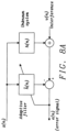
- FIG. 6 A is a diagram of an active control system based on the filtered-x LMS algorithm
- FIG. 6 B is a diagram of another ANC headset according to the disclosure.
- FIG. 7 is a diagram illustrating the working of a sparse filter
- FIG. 8 A is a diagram of an adaptive filter
- FIG. 8 B is a diagram of a modified adaptive filter.
- FIG. 1 is a schematic diagram of an audio device or system provided with active noise cancellation ANC.
- the system 100 comprises a left headphone cup 110 , a right headphone cup 120 and a processing unit 130 for performing ANC.
- the left headphone cup includes a left feedback microphone 114 and a left speaker 116 .
- a feedforward microphone 112 is placed externally to the left headphone cup 110 .
- the right headphone cup includes a right feedback microphone 124 and a right speaker 126 .
- a right feedforward microphone 122 is placed externally to the right headphone cup 120 .
- the processing unit 130 is coupled to the four microphones and to the two speakers to implement a so-called active noise cancellation system (ANC).
- ANC active noise cancellation system
- the active noise cancellation system aims at reducing the environmental noise 104 experienced by the user of the audio system by generated an anti-noise signal.
- the processing unit 130 may be integrated as part of the headphone cups 110 or 120 or both.
- the feedforward microphone 112 detects the environmental noise signal 104 .
- the output of the microphones 112 is sent to the processing unit 130 to be inverted.
- the processing unit 130 then generates a feedforward anti-noise signal provided via the speaker 116 .
- the feedback microphone 114 detects an audio signal inside the headphones cup 110 , at the user's ears.
- the output of the microphone 114 is sent to the processing unit 130 and compared with the environment signal detected by the microphone 112 and the difference is used to create a feedback anti-noise signal.
- the anti-noise signal is a combination of the feedback and feedforward anti-noise signals. When mixed with the environment signal, the anti-noise signal achieves noise cancellation.
- Such an operation is mirrored by the microphones 122 and 124 and speaker 126 on the right side of the audio system.
- the environment signal detected by the feedforward microphones 112 and 122 and the noise signal detected by the feedback microphones 114 and 124 are different as they travel along different acoustic paths.
- complex signal processing of the anti-noise signal(s) is necessary in order to achieve optimal noise suppression at the user's ears.
- the ANC might have to account for attenuation and phase shift experienced by the environmental noise signal when travelling through the headphone cups and/or for noise introduced in the anti-noise signal by the electrical components of the processing unit itself, such as quantization noise.
- the microphones 112 , 114 , 122 and 124 may be analog or digital microphones.
- FIG. 2 is a schematic diagram of a conventional hybrid ANC headset.
- the circuit 200 is shown between a source of acoustic signal providing a signal A which may include sound and noise, and the ear E of a user.
- the circuit 200 corresponds to the left headphone cup of diagram 100 and the same reference numbers have been used to represent corresponding features.
- the circuit 200 includes a feedforward microphone 112 coupled to an ambient to feedforward microphone acoustic transfer function H AFF (it is not modelled internally and represents the path from the noise source A and the feedforward microphone 112 ), a feedback microphone 114 coupled to a drive to feedback transfer function H DFB , a speaker 116 coupled to a speaker driver D and an adder 210 .
- Two equalization filters are also provided: a feedforward filter H FF 230 and a feedback filter H FB 240 .
- the human ear filters H DE and H AE represent the speaker to human ear filter, and the acoustic signal to human ear filter H AE , respectively.
- the circuit 100 can be implemented in either analogue or digital form; however, digital implementation is cheaper to produce and provides greater flexibility.
- the current practice is to implement the equalization filters H FF and H FB as fixed filters which do not change their gain and phase characteristics over time as opposed to adaptive filters which can continually change their gain and phase characteristics to optimize ANC performance.
- the fixed implementation reduces power consumption which is important for applications such as True Wireless Stereo headsets having very small battery capacity.
- fixed filters have several disadvantages as follows. Firstly, the ANC performance is sub optimal when the listening environment is different from the engineering development/tuning environment. This is almost always the case due to differences in the incident angle of the unwanted noise and the anatomy of the headphone wearer. Secondly fixed filters require a time consuming tuning process (of the ANC filters) based on acquiring laboratory measurements. Thirdly, fixed filters require production line calibration to ensure compensating for variability in component tolerance. Successful ANC performance requires accurate equalization of gain and phase to within a few tenths of dB and a few degrees. Finally, fixed filters do not provide for compensation for temperature variations or component ageing.
- FIG. 3 is a flow chart of a method for performing noise cancellation.
- a transducer a first microphone and a first adaptive filter are provided.
- the transducer may be adapted to transform an electrical signal into an acoustic signal such as a speaker.
- an error signal is generated.
- the error signal is based on a difference between a filtered input signal and a signal from the first microphone.
- the filtered input signal is based on a first transfer function estimate of the transducer-to-first microphone transfer function via a first acoustic path.
- the input signal can be any audio signal that is intended for playback on the headset worn by the user, including music, speech from telephone call etc.
- the input signal may be filtered using a digital filter with coefficients updated using an adaptive algorithm such as the normalised least mean squares algorithm to determine the transfer function estimate.
- the coefficients of the first adaptive filter are updated using the error signal.
- a first noise-cancellation signal is generated with the first adaptive filter.
- the method may also include the step of estimating the first transfer function of the transducer-to-first microphone transfer function via the first acoustic path.
- the method 300 may be implemented with a system having one or more adaptive pathways such as feedforward, feedback or a combination of both feedforward and feedback pathways.
- FIG. 4 is a diagram of an ANC headset according to the disclosure.
- the ANC headset 400 includes a feedforward microphone 412 , a feedback microphone 414 , a speaker 416 coupled to an ANC module 420 .
- the ANC module 420 also referred to as ANC controller, includes two adaptive filters 421 and 422 coupled to a calculator adapted to calculate the coefficients of the adaptive filters.
- the filter F 422 is a feedforward adaptive filter for generating feedforward anti-noise signal
- the filter G 421 is feedback adaptive filter for generating a feedback anti-noise signal.
- the ANC module/controller 420 could be implemented as a software module or as a digital circuit or as a combination of both software and digital circuitry.
- the ANC module 420 is implemented as a digital circuit comprising a first set of digital filters labelled 423 a , 423 b , 423 c and 423 d , another digital filter 424 and five combiners or adders labelled 425 a , 425 b , 425 c , 425 d and 425 e .
- the digital filter 423 a is an adaptive filter that can be updated, while the digital filters 423 b , 423 c and 423 d are copies of the filter 423 a .
- the digital filters 423 a , 423 b , 423 c and 423 d may be implemented as a set of identical Finite Impulse Response (FIR) filters, that is having the same order and same coefficients.
- the digital filters 424 , 427 , 428 , 421 and 422 may also be implemented as FIR filters.
- the circuit 400 operates in two stages: a first stage, also referred to as adaptation stage, to update the coefficients of the adaptive filters 427 G and 428 F, and a second stage, also referred to as filtering or ANC cancellation stage, for using the filters 421 G and 422 F as fixed filters in the respective ANC paths.
- the system may implement the first stage and the second stage alternatively (1 st stage/2 nd stage/1 st stage/2 nd stage/ . . . ).
- the system may also implement the first stage at a predefined rate for instance once every N iterations, in which N is an integer.
- the ANC system may be configured to reduce independently the adaptive filter update rate in any path, for instance the FF path or the FB path, to reduce computational complexity and save power.
- the adaptive filter update rate and the ANC filtering rate can be independent relative to each other and independent for each pathway. This can be optimised such that the update rate is fast enough to track the changes in the acoustic scene whilst being lower than the system sampling rate. This can result in significant additional power saving.
- the sampling rate Fs may vary within a specific range, for instance between 96 kHz to 768 kHz.
- the input signal can be any audio signal that is intended for playback on the headset worn by the user, including music, speech from telephone call etc.
- the purpose of the digital filter E 423 a is to remove any component of the input signal which reaches the FB microphone 414 .
- the digital filter 423 a receives the input signal and provides an output signal which is a filtered (convolved) input signal representing an estimate of the microphone signal received at feedback microphone 414 .
- the feedback microphone M(FB) 414 provides a signal S FB that represents the input signal convolved with LAM FB , and the combiner 425 d subtracts the output of 423 a from S FB to obtain an error signal shown as the ANC FB path. If E is a good match for the estimate of L FB , then the output of 423 a and S FB will be the same; i.e. represent the input signal having been filtered with the estimate of the forward path, E, and the input signal filtered by the physical forward path, LAM.
- the only component of the error signal is the noise present at 414 which forms the input to both the adaptive and the fixed FB processing paths.
- the error signal is then sent to various part of the circuit.
- the error signal is feedbacked into the digital filter 423 a for updating the estimate E.
- the error signal is also sent to the adaptive digital filters 427 and 428 for updating their respective coefficients.
- the ANC FB path error signal is also combined, via the combiner 425 b , with an estimate of the ANC signal at the FB microphone 114 provided by the digital filter 423 c.
- the output of the combiner 425 b representing any remaining error is fed to the digital filter 423 b .
- the digital filter 423 b is used to ensure the time alignment of the input signal (via filtering through 423 b ) with the error signal.
- the output of the digital filter 423 b is then used to update the coefficients of the adaptive filter 427 . Therefore, the estimate of G 427 is updated in the feedback ANC path.
- the adaptive filter 423 a can be updated on every sample iteration if there is an input signal present. It must be adapted initially to give an estimate of LAM at start time, but optionally can continually adapt.
- the values of 423 b , 423 c and 423 d will always be the same as E on any given sample iteration.
- the filters 423 b , 423 c and 423 d are not used until E is calculated so their initial state is unimportant but should preferably match the initial state of E for consistency.
- the purpose of the digital filter D 424 is to remove any component of the input signal which reaches the FF microphone 412 .
- the need for D depends on the headphone design and consequently the amount of sound leakage of the input signal via the speaker 416 to the FF microphone 412 .
- the digital filter 424 is configured to determine an estimate D of the speaker (L) 416 to feedforward microphone M(FF) 412 transfer function via the acoustic path C (See equation 5 below).
- the digital filter 424 receives the input signal and provides an output signal which is a filtered (convolved) input signal representing an estimate of the microphone signal received at feedforward microphone 412 .
- the output of 425 e is the FF microphone signal with any input residue removed.
- D has been adapted correctly the only component of the signal is the noise present at 412 which forms the input to both the adaptive and the fixed FF processing paths.
- the error signal is fed back into the digital filter 424 to update D.
- the error signal is also sent to the digital filter 423 d.
- the output of the digital filter 423 d is then used to update the coefficients of the adaptive filter F 428 .
- the adaptive filter 421 G and the adaptive filter 422 F are used directly as fixed filters.
- the transfer function estimate E can be determined using various methods. For instance E can be determined via an adaptive algorithm, such as the Normalised Least Mean Squares (NLMS), (See B. Widrow and S. D. Stearns. Adaptive Signal Processing. Prentice-Hall, 1985.)
- NLMS Normalised Least Mean Squares
- the use of NLMS can be generalised to any method to perform system identification of the unknown plant LAM.
- error( k ) Input T ( k ) ⁇ LAM FB ( k ) ⁇ Input T ( k ) ⁇ E ( k ) (2)
- Input(k) [input(k), input(k ⁇ 1), . . . , input(k ⁇ M+1)] T , where M is the number of taps in the FIR filter and Input T (k) ⁇ LAM FB (k) is the vector inner product of Input T (k) and LAM FB (k).
- E ( k ) [ e 0 ( k ), e l ( k ⁇ 1), . . . , e M-1 ( k )] T (3)
- E(k) is a Finite Impulse Response (FIR) filter with coefficients updated using the NLMS algorithm according to:
- E ⁇ ( k + 1 ) E ⁇ ( k ) + error ( k ) ⁇ Input ( k ) input T ( k ) ⁇ input ( k ) ( 4 )
- the circuit 400 of FIG. 4 is implemented using both a feedback path and a feedforward path, however it will be appreciated that the circuit 400 may also be implemented using only the forward path or only the feedback path. In this case the combiner 425 c would not be necessary. Therefore the proposed architecture supports feedback, feedforward, or a combination of both (hybrid) ANC configurations. Once the transfer function E has been estimated it may be used in whichever feedforward and/or feedback block required. This enables either or both the feedforward and feedback adaptive components to operate.
- FIG. 5 is a schematic diagram of a digital filter.
- the digital filter 500 is a FIR filter of order N having N unit delays 510 in which Z ⁇ 1 is the Z ⁇ 1 operator in Z transform; and a series of N filter coefficients b 0 -b N .
- the output of the y[n] b 0 x[n]+b 1 x[n ⁇ 1]+ . . . +b N x[n ⁇ N] in which x[n ⁇ i] are referred to as taps.
- a conventional adaptive algorithm such as the NLMS algorithm may lead to some instability due to the phase shift (delay) introduced by the forward path LAM.
- the well-known filtered-x LMS-algorithm is, however, an adaptive filter algorithm which is suitable for active control applications.
- FIG. 6 A shows an active control system with a controller based on the filtered-x LMS algorithm as described in “Active Control of Sound”, P. A. Nelson and S. J. Elliott; Academic Press, Inc, 1992; and “The Filtered-x LMS Algorithm” by L. Hakansson, University of Karlskrona, Sweden, 2004.
- FIG. 6 A illustrates the feedforward case in which a model of the dynamic system between the filter output, F, and the forward path estimate, LAM, is introduced between the microphone input signal, M(FF), and the algorithm for the adaptation of the coefficient vector.
- the adaptive filter F 610 is coupled to the digital filter E 620 .
- the output of the digital filter 620 is an estimate of the anti-noise signal that will be received at the FB microphone ( 414 ) (forward path estimate LAM).
- a combiner 630 receives the output of the digital filter 620 and an ambient noise signal and generates an error signal.
- the error signal is the difference between the actual noise signal present at the FB microphone 414 and the anti-noise signal generated by 400 , output at 416 , then received at the microphone 414 .
- the error signal is used in the least mean squares algorithm to change the filter coefficients of the FIR filter F 610 to minimise the square of the error signal.
- the adaptive filter F 610 receives a signal from the feedforward microphone 605 , and provides its output to the digital filter E 620 .
- the output of the adaptive filter F 610 is the estimated anti-noise signal at the FB microphone. This signal is used for the estimate of the adaptive filter coefficients.
- F ⁇ ( k + 1 ) F ⁇ ( k ) + M FB ( k ) ⁇ M FF ( k ) M FF T ( k ) ⁇ M FF ( k ) ( 4 )
- FIG. 6 B is a diagram of another ANC headset according to the disclosure.
- FIG. 6 B is similar to diagram of FIG. 4 (forward path) using the principle described in FIG. 6 A .
- the same reference numerals have been used to represent corresponding components and their description will not be repeated for sake of brevity.
- the feedforward microphone path starting, from the FF microphone 412 produces a feedforward anti-noise cancellation signal. This is achieved using the S FB signal from FB microphone 414 and the estimated transfer function LAM from the filter 423 a to generate an error signal to drive the convergence of the feedforward ANC filter F 428 .
- the path from the feedback microphone is different for adaptation and ANC filtering.
- the pathway goes through the adaptive algorithm is as shown in FIGS. 6 A and 6 B (F equivalent to 428 in FIG. 4 ).
- the filter F (equivalent to 422 in FIG. 4 ) is used in the same sample iteration in the ANC FF path which does not include the estimate, E, of the driver/speaker to microphone path.
- the filter F is then equivalent to H FF 230 in FIG. 2 .
- G ⁇ ( k + 1 ) G ⁇ ( k ) + M FB ( k ) ⁇ M FB ( k ) M FB T ( k ) ⁇ M FB ( k ) ( 7 )
- the frequency of update, F update , to the coefficients F and G can be less than the sampling rate, F S , by an update reduction factor R such that:
- F update is optional; however, this provides a useful means to reduce computation by reducing the rate of updating F and G in equation 8 and 11.
- the update reduction factor, R is related to the stationarity (i.e position in 3D space and noise statistical characteristics) of the acoustic environment and the sampling rate F S .
- R will be higher in feedback than feedforward.
- the ANC module/controller 420 may be implemented using low computational complexity filters, such as sparse filters. This approach permits to reduce computational complexity and save power.
- ANC requires low latency for good performance which corresponds to higher digital sample rates, F S .
- F S digital sample rates
- the use of higher sampling rates increases system power consumption as the filters have a greater number of coefficients and require updating at higher rates.
- the necessity for higher sampling rates, F S has the effect of increasing the bandwidth of the audio path; however, this is not necessary as the ANC cancellation frequency range is typically between 20 Hz and a few kHz.
- the coefficients are set such that most of them are 0, for example only every fourth coefficient might be non-zero.
- a filter which is being updated at a factor X lower than the sampling frequency, a filter can have only 1/X of its coefficients non-zero which allows some practical savings to be made in memory and processing.
- Equation 13 expresses the output y of an FIR filter of length N, where x n is the n th tap in a delay line and c n is the n th filter coefficient.
- equation 14 shows how this sum expands to exclude a large number of taps, meaning that many calculations can be skipped.
- a normal tap buffer can be used along with processing code which skips X samples when it loads the tap line from memory (uses a stride of X). In both cases, computational load is decreased due to storing and using fewer coefficients.
- the value X can be selected such that only one of the sub arrays in the tap line for the update step of the filter is required, saving further memory resources. As such, only the first sub array needs to be kept for the filter adaptation stage, as only one in X of the filtering steps is used.
- FIG. 7 is a diagram illustrating the working of a sparse filter.
- FIG. 7 shows a tap line including 16 taps labelled X 0 to X 15 .
- the tap line 710 can first be rearranged into sub-arrays, in this case four subarrays 722 , 724 , 726 and 728 which store all taps and allow reduced computational load to calculate the filter output.
- the filter then updates coefficients at a reduced sampling rate and does not need to store all taps.
- a low-pass infinite impulse response (IIR) filter may be provided before the FIR filter, to prevent potential aliasing effects due to the system effectively subsampling data. For ANC use-cases this is not a problem because the desired audio bandwidth is low compared to the Nyquist frequency of the system.
- IIR infinite impulse response
- FIG. 8 A shows a typical adaptive filter, where an unknown system with transfer function h(n) is estimated by the adaptive filter, resulting in the estimate ⁇ (n).
- FIG. 8 B shows the adaptive filter for use in the system of the disclosure in which the adaptive filter component is preceded by a low-pass filter.
- This technique works best with long FIR filters (typical with ANC filters at high sampling frequencies) where the savings made by reducing the FIR processing load more than compensate for some additional IIR pre-processing.
- the FIR filter which the system converges upon will be affected by the transfer function of the IIR, most notably in the ANC case, the group delay. This results in the estimate ⁇ (n) being composed of the convolution of the low-pass filter transfer function and the adapted transfer function.
- the low-pass component must then be run at the original sampling rate of the system, not the lower rate obtained by dividing by X.
- the system and method of the disclosure reduces the power consumption of adaptive ANC systems compared to the current state of the art and present several other advantages.
- the system of the disclosure can adapt the gain and phase of the adaptive filter(s) to best match the noise direction and wearer's anatomy.
- the proposed system does not require laboratory-based acoustic measurements to be made. It is also self-calibrating at runtime as the filters are all adaptive at runtime. Consequently, any difference in gain and phase response between samples of the microphones, speakers or acoustics at the point of manufacture can be compensated for in the adaptive filters. For instance, a + ⁇ 3 dB difference in microphone sensitivity at manufacture time could be compensated for with in the overall gain of the filter E, F and G. Similarly, the proposed system can compensate for temperature and ageing components at runtime.
- the systems and methods of the disclosure may be implemented using a computer-readable data carrier or a computer readable medium having stored thereon instructions which when executed by a computer enables to act as the ANC module/controller presented above.
- a computer program product may be stored on or transmitted as one or more instructions or code on a computer-readable medium.
- Computer-readable media includes both computer storage media and communication media including any medium that facilitates transfer of a computer program from one place to another.
- a storage media may be any available media that can be accessed by a computer.
- Such computer-readable media can comprise RAM, ROM, EEPROM, CD-ROM or other optical disk storage, magnetic disk storage or other magnetic storage devices, or any other medium that can be used to carry or store desired program code in the form of instructions or data structures and that can be accessed by a computer.
- any connection is properly termed a computer-readable medium.
- the instructions or code associated with a computer-readable medium of the computer program product may be executed by a computer, e.g., by one or more processors, such as one or more digital signal processors (DSPs), general purpose microprocessors, ASICs, FPGAs, or other equivalent integrated or discrete logic circuitry.
- processors such as one or more digital signal processors (DSPs), general purpose microprocessors, ASICs, FPGAs, or other equivalent integrated or discrete logic circuitry.
Landscapes
- Physics & Mathematics (AREA)
- Engineering & Computer Science (AREA)
- Acoustics & Sound (AREA)
- Multimedia (AREA)
- Soundproofing, Sound Blocking, And Sound Damping (AREA)
Abstract
An active noise cancellation (ANC) system is presented. The ANC system includes a transducer; a first microphone; and a first adaptive filter coupled to a calculator. The calculator generates an error signal based on a difference between a filtered input signal and a signal from the first microphone. The filtered input signal is based on a first transfer function estimate of the transducer-to-first microphone transfer function via a first acoustic path. The calculator updates coefficients of the first adaptive filter using the error signal and generates with the first adaptive filter a first noise-cancellation signal.
Description
The present disclosure relates to an active noise cancellation system and to a method for cancelling noise. In particular, the present disclosure relates to a low-power active noise cancellation system.
Headset Active Noise Cancellation (ANC) enables cancellation of unwanted local environmental acoustic noise, creating the impression of a quiet ambient environment for listeners, whilst optionally leaving desired music/audio signals to be heard without signal degradation. ANC is achieved by producing audio signals with equal amplitude but opposite phase to the ambient noise at the listeners' ear using the principle of destructive wave interference to cancel unwanted extraneous noise. A typical application field of the ANC operation are the various types of headphones distinguished by the type of fitting on the listener's ear: in-ear, on-ear and over-ear.
There are typically two types of ANC: feedback (FB) ANC and feedforward (FF) ANC. A FB ANC system has microphones placed inside the headset in close proximity to the speaker driver, capturing soundwaves close to the eardrum. FF ANC system microphones are situated externally on the headset, capturing ambient noise before it passes through the headset to the eardrum. In addition, these two designs can be combined to produce a hybrid ANC system which has superior overall performance to either FB or FF ANC systems individual performance.
Current ANC systems use equalization filters implemented as fixed filters which do not change their gain and phase characteristics over time. or adaptive filters which can continually change their gain and phase characteristics to optimize ANC performance.
The fixed implementation reduces power consumption which is important for applications such as True Wireless Stereo headsets having very small battery capacity. However, fixed filters have several disadvantages including i) sub optimal performance when the listening environment is different from the engineering development/tuning environment; ii) the need for time consuming tuning process necessitating acquiring laboratory measurements and tuning the ANC filters; iii) production line calibration requirements to ensure matching for variability in component tolerance; iv) no provision for compensation for temperature variations or ageing components.
It is an object of the disclosure to address one or more of the above mentioned limitations.
According to a first aspect of the disclosure, there is provided an active noise cancellation system comprising a transducer; a first microphone; and a first adaptive filter coupled to a calculator; the calculator being configured to generate an error signal based on a difference between a filtered input signal and a signal from the first microphone, wherein the filtered input signal is based on a first transfer function estimate of the transducer-to-first microphone transfer function via a first acoustic path, to update coefficients of the first adaptive filter using the error signal, and to generate with the first adaptive filter a first noise-cancellation signal.
For instance the transducer may be a speaker and the first microphone may be a feedback microphone.
Optionally, the coefficients are updated at an update rate and wherein the calculator is configured to adjust the update rate.
Optionally, the adaptive filter coefficients are updated at a lower rate than a sampling rate.
Optionally, the calculator is configured to estimate the first transfer function of the transducer-to-first microphone transfer function via the first acoustic path.
Optionally, the calculator comprises an estimator digital filter configured to estimate the first transfer function and to provide the filtered input signal.
Optionally, the calculator comprises a set of digital filters arranged along several paths to update the first adaptive filter.
Optionally, wherein each digital filter in the set of digital filters is identical to the estimator digital filter.
Optionally, at least one of the first adaptive filter and the estimator digital filter is a sparse filter in which filter taps are divided in subsets of filter taps.
Optionally, wherein sparse filter coefficients corresponding to specific subsets of filter taps are set to zero.
Optionally, the calculator is configured to estimate the first transfer function using an adaptive algorithm.
Optionally, wherein the adaptive algorithm comprises at least one of a Normalised Least Mean Squares algorithm and a filtered-x Least Mean Squares algorithm.
Optionally, the active noise cancellation system comprises a second microphone; and a second adaptive filter coupled to the calculator; the calculator being configured to update coefficients of the second adaptive filter using the error signal, and to generate with the second adaptive filter a second noise-cancellation signal.
For instance the second microphone may be a feedforward microphone.
Optionally, the calculator comprises another estimator digital filter configured to estimate a second transfer function, wherein the second transfer function estimate is an estimate of the transducer-to-second microphone transfer function via a second acoustic path.
Optionally, wherein the calculator is configured to generate a second error signal based on a difference between a second filtered input signal and a signal from the second microphone, wherein the second filtered input signal is based on the second transfer function estimate.
Optionally, the calculator is configured to update coefficients of the second adaptive filter using the second error signal.
Optionally, wherein the system is operable in two stages: a first stage to update the coefficients of the first adaptive filter, and a second stage to use the first adaptive filter as fixed filter.
For instance the system may implement the first stage and the second stage alternatively (first stage/second stage). The system may also implement the first stage at a predefined rate for instance once every N iterations, in which N is an integer.
According to a second aspect of the disclosure, there is provided an audio device comprising an active noise cancellation system according to the first aspect.
According to a third aspect of the disclosure there is provided a method for cancelling noise, the method comprising providing a transducer, a first microphone and a first adaptive filter; generating an error signal based on a difference between a filtered input signal and a signal from the first microphone, wherein the filtered input signal is based on a first transfer function estimate of the transducer-to-first microphone transfer function via a first acoustic path, updating coefficients of the first adaptive filter using the error signal, and generating with the first adaptive filter a first noise-cancellation signal.
Optionally, the method comprises estimating the first transfer function of the transducer-to-first microphone transfer function via the first acoustic path. According to a fourth aspect of the disclosure there is provided a computer-readable data carrier having stored thereon instructions which when executed by a computer cause the computer to generate an error signal based on a difference between a filtered input signal and a signal from a first microphone, wherein the filtered input signal is based on a first transfer function estimate of the transducer-to-first microphone transfer function via a first acoustic path, update coefficients of the first adaptive filter using the error signal, and generate with the first adaptive filter a first noise-cancellation signal.
The options described with respect to the first aspect of the disclosure are also common to the second, third and fourth aspects of the disclosure.
The disclosure is described in further detail below by way of example and with reference to the accompanying drawings, in which:
In operation, the feedforward microphone 112 detects the environmental noise signal 104. The output of the microphones 112 is sent to the processing unit 130 to be inverted. The processing unit 130 then generates a feedforward anti-noise signal provided via the speaker 116. The feedback microphone 114 detects an audio signal inside the headphones cup 110, at the user's ears. The output of the microphone 114 is sent to the processing unit 130 and compared with the environment signal detected by the microphone 112 and the difference is used to create a feedback anti-noise signal. The anti-noise signal is a combination of the feedback and feedforward anti-noise signals. When mixed with the environment signal, the anti-noise signal achieves noise cancellation. Such an operation is mirrored by the microphones 122 and 124 and speaker 126 on the right side of the audio system.
The environment signal detected by the feedforward microphones 112 and 122 and the noise signal detected by the feedback microphones 114 and 124 are different as they travel along different acoustic paths. As a result complex signal processing of the anti-noise signal(s) is necessary in order to achieve optimal noise suppression at the user's ears. For example, the ANC might have to account for attenuation and phase shift experienced by the environmental noise signal when travelling through the headphone cups and/or for noise introduced in the anti-noise signal by the electrical components of the processing unit itself, such as quantization noise. The microphones 112, 114, 122 and 124 may be analog or digital microphones.
The circuit 100 can be implemented in either analogue or digital form; however, digital implementation is cheaper to produce and provides greater flexibility.
The current practice is to implement the equalization filters HFF and HFB as fixed filters which do not change their gain and phase characteristics over time as opposed to adaptive filters which can continually change their gain and phase characteristics to optimize ANC performance. The fixed implementation reduces power consumption which is important for applications such as True Wireless Stereo headsets having very small battery capacity. However, fixed filters have several disadvantages as follows. Firstly, the ANC performance is sub optimal when the listening environment is different from the engineering development/tuning environment. This is almost always the case due to differences in the incident angle of the unwanted noise and the anatomy of the headphone wearer. Secondly fixed filters require a time consuming tuning process (of the ANC filters) based on acquiring laboratory measurements. Thirdly, fixed filters require production line calibration to ensure compensating for variability in component tolerance. Successful ANC performance requires accurate equalization of gain and phase to within a few tenths of dB and a few degrees. Finally, fixed filters do not provide for compensation for temperature variations or component ageing.
At step 310 a transducer, a first microphone and a first adaptive filter are provided. For instance the transducer may be adapted to transform an electrical signal into an acoustic signal such as a speaker.
At step 320 an error signal is generated. The error signal is based on a difference between a filtered input signal and a signal from the first microphone. The filtered input signal is based on a first transfer function estimate of the transducer-to-first microphone transfer function via a first acoustic path.
The input signal can be any audio signal that is intended for playback on the headset worn by the user, including music, speech from telephone call etc. The input signal may be filtered using a digital filter with coefficients updated using an adaptive algorithm such as the normalised least mean squares algorithm to determine the transfer function estimate.
At step 330, the coefficients of the first adaptive filter are updated using the error signal.
At step 340 a first noise-cancellation signal is generated with the first adaptive filter.
The method may also include the step of estimating the first transfer function of the transducer-to-first microphone transfer function via the first acoustic path.
The method 300 may be implemented with a system having one or more adaptive pathways such as feedforward, feedback or a combination of both feedforward and feedback pathways.
The ANC module/controller 420 could be implemented as a software module or as a digital circuit or as a combination of both software and digital circuitry.
In FIG. 4 the ANC module 420 is implemented as a digital circuit comprising a first set of digital filters labelled 423 a, 423 b, 423 c and 423 d, another digital filter 424 and five combiners or adders labelled 425 a, 425 b, 425 c, 425 d and 425 e. The digital filter 423 a is an adaptive filter that can be updated, while the digital filters 423 b, 423 c and 423 d are copies of the filter 423 a. The digital filters 423 a, 423 b, 423 c and 423 d may be implemented as a set of identical Finite Impulse Response (FIR) filters, that is having the same order and same coefficients. The digital filters 424, 427, 428, 421 and 422 may also be implemented as FIR filters.
The circuit 400 operates in two stages: a first stage, also referred to as adaptation stage, to update the coefficients of the adaptive filters 427 G and 428 F, and a second stage, also referred to as filtering or ANC cancellation stage, for using the filters 421 G and 422 F as fixed filters in the respective ANC paths. The system may implement the first stage and the second stage alternatively (1st stage/2nd stage/1st stage/2nd stage/ . . . ). The system may also implement the first stage at a predefined rate for instance once every N iterations, in which N is an integer.
For example (1st stage/2nd stage/2nd stage/2nd stage/1st stage/ . . . ).
The ANC system may be configured to reduce independently the adaptive filter update rate in any path, for instance the FF path or the FB path, to reduce computational complexity and save power. The adaptive filter update rate and the ANC filtering rate can be independent relative to each other and independent for each pathway. This can be optimised such that the update rate is fast enough to track the changes in the acoustic scene whilst being lower than the system sampling rate. This can result in significant additional power saving.
The sampling rate Fs may vary within a specific range, for instance between 96 kHz to 768 kHz. The input signal can be any audio signal that is intended for playback on the headset worn by the user, including music, speech from telephone call etc.
The digital filter 423 a, also referred to as first estimator, is configured to determine an estimate E of the speaker (L) 416 to feedback microphone M(FB) 414 transfer function via the acoustic path A, such that:
E=L FB (1)
E=L
The purpose of the digital filter E 423 a is to remove any component of the input signal which reaches the FB microphone 414. In the first stage the digital filter 423 a receives the input signal and provides an output signal which is a filtered (convolved) input signal representing an estimate of the microphone signal received at feedback microphone 414. The feedback microphone M(FB) 414 provides a signal SFB that represents the input signal convolved with LAMFB, and the combiner 425 d subtracts the output of 423 a from SFB to obtain an error signal shown as the ANC FB path. If E is a good match for the estimate of L FB, then the output of 423 a and SFB will be the same; i.e. represent the input signal having been filtered with the estimate of the forward path, E, and the input signal filtered by the physical forward path, LAM.
When E has been adapted correctly the only component of the error signal is the noise present at 414 which forms the input to both the adaptive and the fixed FB processing paths. The error signal is then sent to various part of the circuit. The error signal is feedbacked into the digital filter 423 a for updating the estimate E. The error signal is also sent to the adaptive digital filters 427 and 428 for updating their respective coefficients. The ANC FB path error signal is also combined, via the combiner 425 b, with an estimate of the ANC signal at the FB microphone 114 provided by the digital filter 423 c.
The output of the combiner 425 b representing any remaining error is fed to the digital filter 423 b. The digital filter 423 b is used to ensure the time alignment of the input signal (via filtering through 423 b) with the error signal. The output of the digital filter 423 b is then used to update the coefficients of the adaptive filter 427. Therefore, the estimate of G 427 is updated in the feedback ANC path.
The adaptive filter 423 a can be updated on every sample iteration if there is an input signal present. It must be adapted initially to give an estimate of LAM at start time, but optionally can continually adapt. The values of 423 b, 423 c and 423 d will always be the same as E on any given sample iteration. The filters 423 b, 423 c and 423 d are not used until E is calculated so their initial state is unimportant but should preferably match the initial state of E for consistency.
Similar to the digital filter E 423 a, the purpose of the digital filter D 424 is to remove any component of the input signal which reaches the FF microphone 412. The need for D depends on the headphone design and consequently the amount of sound leakage of the input signal via the speaker 416 to the FF microphone 412.
The digital filter 424 is configured to determine an estimate D of the speaker (L) 416 to feedforward microphone M(FF) 412 transfer function via the acoustic path C (See equation 5 below).
The digital filter 424 receives the input signal and provides an output signal which is a filtered (convolved) input signal representing an estimate of the microphone signal received at feedforward microphone 412. The feedforward microphone M(FF) 412 provides a signal SFF and the combiner 425 e subtracts the input signal filtered using 424 from SFF to remove any input residue signal from SFF and obtain an error signal shown as the ANC FF path. If input*D=input*LCMFF, (see equation 5 below) then all the input residues will be removed.
The output of 425 e is the FF microphone signal with any input residue removed. When D has been adapted correctly the only component of the signal is the noise present at 412 which forms the input to both the adaptive and the fixed FF processing paths. The error signal is fed back into the digital filter 424 to update D. The error signal is also sent to the digital filter 423 d.
The output of the digital filter 423 d is then used to update the coefficients of the adaptive filter F 428. Then in the second stage the adaptive filter 421 G and the adaptive filter 422 F are used directly as fixed filters.
The transfer function estimate E can be determined using various methods. For instance E can be determined via an adaptive algorithm, such as the Normalised Least Mean Squares (NLMS), (See B. Widrow and S. D. Stearns. Adaptive Signal Processing. Prentice-Hall, 1985.) The use of NLMS can be generalised to any method to perform system identification of the unknown plant LAM.
Using this approach the error at each sampling interval k can be expressed as:
error(k)=InputT(k)·LAM FB(k)−InputT(k)·E(k) (2)
error(k)=InputT(k)·LAM FB(k)−InputT(k)·E(k) (2)
In which the term (InputT(k)·LAMFB(k)) represents the signal SFB from microphone 414, and (InputT(k)·E(k)) represents the output of the digital filter 423 a, hence the input signal filtered using the digital filter 423 a.
With Input(k)=[input(k), input(k−1), . . . , input(k−M+1)]T, where M is the number of taps in the FIR filter and InputT(k)·LAMFB(k) is the vector inner product of InputT(k) and LAMFB(k).
E(k)=[e 0(k),e l(k−1), . . . ,e M-1(k)]T (3)
E(k)=[e 0(k),e l(k−1), . . . ,e M-1(k)]T (3)
E(k) is a Finite Impulse Response (FIR) filter with coefficients updated using the NLMS algorithm according to:
It is also possible there may be leakage from the loudspeaker, L, to the feedforward microphone M (FF). The digital filter 424 is configured to determine an estimate D of the speaker (L) 416 to feedforward microphone M(FF) 412 transfer function via the acoustic path C, such that:
D=L FF (1)
D=L
The circuit 400 of FIG. 4 is implemented using both a feedback path and a feedforward path, however it will be appreciated that the circuit 400 may also be implemented using only the forward path or only the feedback path. In this case the combiner 425 c would not be necessary. Therefore the proposed architecture supports feedback, feedforward, or a combination of both (hybrid) ANC configurations. Once the transfer function E has been estimated it may be used in whichever feedforward and/or feedback block required. This enables either or both the feedforward and feedback adaptive components to operate.
A conventional adaptive algorithm such as the NLMS algorithm may lead to some instability due to the phase shift (delay) introduced by the forward path LAM. The well-known filtered-x LMS-algorithm is, however, an adaptive filter algorithm which is suitable for active control applications.
The adaptive filter F 610 is coupled to the digital filter E 620. The output of the digital filter 620 is an estimate of the anti-noise signal that will be received at the FB microphone (414) (forward path estimate LAM).
A combiner 630 receives the output of the digital filter 620 and an ambient noise signal and generates an error signal. The error signal is the difference between the actual noise signal present at the FB microphone 414 and the anti-noise signal generated by 400, output at 416, then received at the microphone 414.
The error signal is used in the least mean squares algorithm to change the filter coefficients of the FIR filter F 610 to minimise the square of the error signal. The adaptive filter F 610 receives a signal from the feedforward microphone 605, and provides its output to the digital filter E 620. The output of the adaptive filter F 610 is the estimated anti-noise signal at the FB microphone. This signal is used for the estimate of the adaptive filter coefficients.
The adaptive filter coefficients in the adaptive filter F are updated in the same way as those of E in the above description, namely:
M FB =N+M FF ·F·LAM FB (2)
M FB =N+M FF ·F·LAM FB (2)
Therefore at each sampling interval, k
M FB(k)=N T(k)+M FF T(k)·F(k)LAM FB(k) (3)
M FB(k)=N T(k)+M FF T(k)·F(k)LAM FB(k) (3)
Where LAMFB(k) is modelled by E(k). Consequently, the coefficients of the FIR filter are updated using the NLMS according to:
The diagram of FIG. 6B is similar to diagram of FIG. 4 (forward path) using the principle described in FIG. 6A . The same reference numerals have been used to represent corresponding components and their description will not be repeated for sake of brevity.
Like in in FIG. 4 , the feedforward microphone path starting, from the FF microphone 412, produces a feedforward anti-noise cancellation signal. This is achieved using the SFB signal from FB microphone 414 and the estimated transfer function LAM from the filter 423 a to generate an error signal to drive the convergence of the feedforward ANC filter F 428.
The path from the feedback microphone is different for adaptation and ANC filtering. During adaptation of the digital filter F, the pathway goes through the adaptive algorithm is as shown in FIGS. 6A and 6B (F equivalent to 428 in FIG. 4 ). Once the updated version of the filter F has been created, the filter F (equivalent to 422 in FIG. 4 ) is used in the same sample iteration in the ANC FF path which does not include the estimate, E, of the driver/speaker to microphone path. The filter F is then equivalent to H FF 230 in FIG. 2 .
If a feedback ANC component is present, then the adaptive filter coefficients in G (427) are updated in the same way as those of F in the feedforward description, namely:
M FB =N+M FB ·G·LAM FB (5)
M FB =N+M FB ·G·LAM FB (5)
Therefore at each sampling interval, k
M FB(k)=N T(k)+M FB T(k)·G(k)LAM FB(k) (6)
M FB(k)=N T(k)+M FB T(k)·G(k)LAM FB(k) (6)
Where LAMFB(k) is modelled by E(k). Consequently, the coefficients of the FIR filter are updated using the NLMS according to:
The frequency of update, Fupdate, to the coefficients F and G can be less than the sampling rate, FS, by an update reduction factor R such that:
The use of Fupdate is optional; however, this provides a useful means to reduce computation by reducing the rate of updating F and G in equation 8 and 11.
The update reduction factor, R, is related to the stationarity (i.e position in 3D space and noise statistical characteristics) of the acoustic environment and the sampling rate FS. Typically R will be higher in feedback than feedforward.
The ANC module/controller 420 may be implemented using low computational complexity filters, such as sparse filters. This approach permits to reduce computational complexity and save power. ANC requires low latency for good performance which corresponds to higher digital sample rates, FS. The use of higher sampling rates increases system power consumption as the filters have a greater number of coefficients and require updating at higher rates. The necessity for higher sampling rates, FS, has the effect of increasing the bandwidth of the audio path; however, this is not necessary as the ANC cancellation frequency range is typically between 20 Hz and a few kHz.
Within a sparse filter, the coefficients are set such that most of them are 0, for example only every fourth coefficient might be non-zero. In the case of a filter which is being updated at a factor X lower than the sampling frequency, a filter can have only 1/X of its coefficients non-zero which allows some practical savings to be made in memory and processing.
The equation 13 below expresses the output y of an FIR filter of length N, where xn is the nth tap in a delay line and cn is the nth filter coefficient.
With X=4, equation 14 shows how this sum expands to exclude a large number of taps, meaning that many calculations can be skipped.
As the tap line is updated with every new sample input to the filter, it becomes advantageous to store taps in X sub-arrays, such that samples separated by X other samples are contiguous in memory. This allows the same shortened filtering loop implementing equation 14 to be used for every input while keeping filter tap history intact and reducing the number of coefficients to be stored, as zero-valued coefficients are unused. Alternatively, a normal tap buffer can be used along with processing code which skips X samples when it loads the tap line from memory (uses a stride of X). In both cases, computational load is decreased due to storing and using fewer coefficients.
When the filter coefficients are updated at a lower rate than the sampling rate, the value X can be selected such that only one of the sub arrays in the tap line for the update step of the filter is required, saving further memory resources. As such, only the first sub array needs to be kept for the filter adaptation stage, as only one in X of the filtering steps is used.
A low-pass infinite impulse response (IIR) filter may be provided before the FIR filter, to prevent potential aliasing effects due to the system effectively subsampling data. For ANC use-cases this is not a problem because the desired audio bandwidth is low compared to the Nyquist frequency of the system.
The system and method of the disclosure reduces the power consumption of adaptive ANC systems compared to the current state of the art and present several other advantages.
The system of the disclosure can adapt the gain and phase of the adaptive filter(s) to best match the noise direction and wearer's anatomy. The proposed system does not require laboratory-based acoustic measurements to be made. It is also self-calibrating at runtime as the filters are all adaptive at runtime. Consequently, any difference in gain and phase response between samples of the microphones, speakers or acoustics at the point of manufacture can be compensated for in the adaptive filters. For instance, a +−3 dB difference in microphone sensitivity at manufacture time could be compensated for with in the overall gain of the filter E, F and G. Similarly, the proposed system can compensate for temperature and ageing components at runtime.
The systems and methods of the disclosure may be implemented using a computer-readable data carrier or a computer readable medium having stored thereon instructions which when executed by a computer enables to act as the ANC module/controller presented above.
A computer program product may be stored on or transmitted as one or more instructions or code on a computer-readable medium. Computer-readable media includes both computer storage media and communication media including any medium that facilitates transfer of a computer program from one place to another. A storage media may be any available media that can be accessed by a computer. By way of example such computer-readable media can comprise RAM, ROM, EEPROM, CD-ROM or other optical disk storage, magnetic disk storage or other magnetic storage devices, or any other medium that can be used to carry or store desired program code in the form of instructions or data structures and that can be accessed by a computer. Also, any connection is properly termed a computer-readable medium. The instructions or code associated with a computer-readable medium of the computer program product may be executed by a computer, e.g., by one or more processors, such as one or more digital signal processors (DSPs), general purpose microprocessors, ASICs, FPGAs, or other equivalent integrated or discrete logic circuitry.
A skilled person will therefore appreciate that variations of the disclosed arrangements are possible without departing from the disclosure. Accordingly, the above description of the specific embodiments is made by way of example only and not for the purposes of limitation. It will be clear to the skilled person that minor modifications may be made without significant changes to the operation described.
Claims (16)
1. An active noise cancellation system comprising
a transducer;
a first microphone;
a first adaptive filter; and
a calculator coupled to the first adaptive filter, wherein the calculator comprises a set of digital filters arranged along several paths to update the first adaptive filter; the calculator being configured
to generate an error signal based on a difference between a filtered input signal and a signal from the first microphone, wherein the filtered input signal is based on a first transfer function estimate of the transducer-to-first microphone transfer function via a first acoustic path,
to update coefficients of the first adaptive filter using the error signal, and
to generate with the first adaptive filter a first noise-cancellation signal;
wherein the calculator is configured to estimate the first transfer function of the transducer-to-first microphone transfer function via the first acoustic path; wherein the calculator comprises an estimator digital filter configured to estimate the first transfer function and to provide the filtered input signal; and
wherein the calculator is configured to estimate the first transfer function using an adaptive algorithm.
2. The active noise cancellation system as claimed in claim 1 , wherein the coefficients are updated at an update rate and wherein the calculator is configured to adjust the update rate.
3. The active noise cancellation system as claimed in claim 1 , wherein the adaptive filter coefficients are updated at a lower rate than a sampling rate.
4. The active noise cancellation system as claimed in claim 1 , wherein each digital filter in the set of digital filters is identical to the estimator digital filter.
5. The active noise cancellation system as claimed in claim 1 , wherein at least one of the first adaptive filter and the estimator digital filter is a sparse filter in which filter taps are divided in subsets of filter taps.
6. The active noise cancellation system as claimed in claim 5 , wherein sparse filter coefficients corresponding to specific subsets of filter taps are set to zero.
7. The active noise cancellation system as claimed in claim 1 , wherein the adaptive algorithm comprises at least one of a Normalised Least Mean Squares algorithm and a filtered-x Least Mean Squares algorithm.
8. The active noise cancellation system as claimed in claim 1 , comprising
a second microphone; and
a second adaptive filter coupled to the calculator; the calculator being configured
to update coefficients of the second adaptive filter using the error signal, and
to generate with the second adaptive filter a second noise-cancellation signal.
9. The active noise cancellation system as claimed in claim 1 , wherein the system is operable in two stages: a first stage to update the coefficients of the first adaptive filter, and a second stage to use the first adaptive filter as fixed filter.
10. An active noise cancellation system comprising a transducer; a first microphone; a first adaptive filter coupled to a calculator; the calculator being configured
to generate an error signal based on a difference between a filtered input signal and a signal from the first microphone, wherein the filtered input signal is based on a first transfer function estimate of the transducer-to-first microphone transfer function via a first acoustic path, to update coefficients of the first adaptive filter using the error signal, and to generate with the first adaptive filter a first noise-cancellation signal;
a second microphone; and
a second adaptive filter coupled to the calculator; the calculator being configured to update coefficients of the second adaptive filter using the error signal, and to generate with the second adaptive filter a second noise-cancellation signal, wherein the calculator comprises another estimator digital filter configured to estimate a second transfer function, wherein the second transfer function estimate is an estimate of the transducer-to-second microphone transfer function via a second acoustic path.
11. The active noise cancellation system as claimed in claim 10 , wherein the calculator is configured to generate a second error signal based on a difference between a second filtered input signal and a signal from the second microphone, wherein the second filtered input signal is based on the second transfer function estimate.
12. The active noise cancellation system as claimed in claim 1 , wherein the calculator is configured to update coefficients of the second adaptive filter using the second error signal.
13. An audio device comprising an active noise cancellation system as claimed in claim 1 .
14. A method for cancelling noise, the method comprising
providing a transducer, a first microphone, a first adaptive filter and a calculator, wherein the calculator comprises a set of digital filters arranged along several paths to update the first adaptive filter;
generating an error signal based on a difference between a filtered input signal and a signal from the first microphone, wherein the filtered input signal is based on a first transfer function estimate of the transducer-to-first microphone transfer function via a first acoustic path,
updating coefficients of the first adaptive filter using the error signal, and
generating with the first adaptive filter a first noise-cancellation signal;
using the calculator, estimating the first transfer function of the transducer-to-first microphone transfer function via the first acoustic path;
wherein the calculator comprises an estimator digital filter configured to estimate the first transfer function and to provide the filtered input signal, and
wherein the calculator is configured to estimate the first transfer function using an adaptive algorithm.
15. A non-transitory computer-readable data carrier having stored thereon instructions which when executed by a computer cause the computer to
estimate with an estimator digital filter a first transfer function of a transducer-to-first microphone transfer function via a first acoustic path; generate an error signal based on a difference between a filtered input signal and a signal from a first microphone, wherein the filtered input signal is based on the first transfer function estimate of the transducer-to-first microphone transfer function via a first acoustic path,
update coefficients of the first adaptive filter using the error signal via a set of digital filters arranged along several paths and
generate with the first adaptive filter a first noise-cancellation signal;
wherein the first transfer function is estimated using an adaptive algorithm.
16. An active noise cancellation system comprising
a transducer;
a first microphone; and
a first adaptive filter coupled to a calculator; the calculator being configured to
generate an error signal based on a difference between a filtered input signal and a signal from the first microphone, wherein the filtered input signal is based on a first transfer function estimate of the transducer-to-first microphone transfer function via a first acoustic path,
to update coefficients of the first adaptive filter using the error signal, and
to generate with the first adaptive filter a first noise-cancellation signal, wherein the first adaptive filter is a sparse filter in which filter taps are divided in subsets of filter taps.
Priority Applications (1)
| Application Number | Priority Date | Filing Date | Title |
|---|---|---|---|
| US17/695,528 US12057099B1 (en) | 2022-03-15 | 2022-03-15 | Active noise cancellation system |
Applications Claiming Priority (1)
| Application Number | Priority Date | Filing Date | Title |
|---|---|---|---|
| US17/695,528 US12057099B1 (en) | 2022-03-15 | 2022-03-15 | Active noise cancellation system |
Publications (1)
| Publication Number | Publication Date |
|---|---|
| US12057099B1 true US12057099B1 (en) | 2024-08-06 |
Family
ID=92121040
Family Applications (1)
| Application Number | Title | Priority Date | Filing Date |
|---|---|---|---|
| US17/695,528 Active US12057099B1 (en) | 2022-03-15 | 2022-03-15 | Active noise cancellation system |
Country Status (1)
| Country | Link |
|---|---|
| US (1) | US12057099B1 (en) |
Cited By (3)
| Publication number | Priority date | Publication date | Assignee | Title |
|---|---|---|---|---|
| US20240112664A1 (en) * | 2022-09-27 | 2024-04-04 | Luxshare Precision Technology(Nanjing)Co., Ltd | Headset device with speakers, signal processing method and analysis system thereof |
| US20240205588A1 (en) * | 2021-04-30 | 2024-06-20 | Sony Group Corporation | Information processing apparatus, information processing method, and program |
| CN119993186A (en) * | 2025-04-08 | 2025-05-13 | 深圳晨芯时代科技有限公司 | Wireless audio effect processing method and system |
Citations (49)
| Publication number | Priority date | Publication date | Assignee | Title |
|---|---|---|---|---|
| US5262972A (en) | 1991-07-17 | 1993-11-16 | Hughes Missile Systems Company | Multichannel digital filter apparatus and method |
| US5301134A (en) | 1991-01-30 | 1994-04-05 | Nec Corporation | Digital filter circuit for use in oversampling type analog/digital converter |
| US5305307A (en) | 1991-01-04 | 1994-04-19 | Picturetel Corporation | Adaptive acoustic echo canceller having means for reducing or eliminating echo in a plurality of signal bandwidths |
| US5757299A (en) | 1994-09-30 | 1998-05-26 | Yamaha Corporation | Analog-Digital converter using delta sigma modulation digital filtering, and gain-scaling |
| US5757862A (en) | 1995-09-18 | 1998-05-26 | Mitsubishi Denki Kabushiki Kaisha | Demodulator, modulation and demodulation system, and demodulation method |
| US5784378A (en) | 1996-05-30 | 1998-07-21 | Analog Devices, Inc. | Method and apparatus for time shaped finite impulse response filter with multiple signal stream capability |
| US5805479A (en) | 1995-09-25 | 1998-09-08 | United Microelectronics Corp. | Apparatus and method for filtering digital signals |
| US5904731A (en) | 1994-07-28 | 1999-05-18 | Fujitsu Limited | Product-sum device suitable for IIR and FIR operations |
| US5946650A (en) | 1997-06-19 | 1999-08-31 | Tritech Microelectronics, Ltd. | Efficient pitch estimation method |
| US20050008071A1 (en) | 2003-07-08 | 2005-01-13 | Tamal Bose | Infinite impulse response multiplierless digital filter architecture |
| US20050053227A1 (en) | 2003-07-17 | 2005-03-10 | John Fortier | Electronic circuit to reduce noise in digital subscriber loop and communications over unshielded twisted pair metallic conductors |
| US7058190B1 (en) | 2000-05-22 | 2006-06-06 | Harman Becker Automotive Systems-Wavemakers, Inc. | Acoustic signal enhancement system |
| US20070188218A1 (en) | 2004-03-22 | 2007-08-16 | Matsushita Electric Industrial Co., Ltd | Peak power suppressor and peak power suppressing method |
| US20070273446A1 (en) | 2006-05-23 | 2007-11-29 | Samsung Electronics Co., Ltd. | Automatic input-gain control circuit and method thereof |
| US20070285160A1 (en) | 2006-06-07 | 2007-12-13 | Samsung Electronics Co., Ltd. | Input-gain control apparatus and method |
| US20080225168A1 (en) | 2007-03-14 | 2008-09-18 | Chris Ouslis | Method and apparatus for processing a television signal with a coarsely positioned if frequency |
| US20080250093A1 (en) | 2005-10-13 | 2008-10-09 | Nxp B.V. | Method and Apparatus for Filtering Multiple Channels of Signals |
| US7636747B2 (en) | 2006-11-22 | 2009-12-22 | Toyota Jidosha Kabushiki Kaisha | Digital low-pass filter |
| US7652604B2 (en) | 2007-02-28 | 2010-01-26 | Exar Corporation | Programmable analog-to-digital converter for low-power DC-DC SMPS |
| US7756222B2 (en) | 2006-05-04 | 2010-07-13 | Integrated System Solution Corporation | Adaptive quantization method and apparatus for an OFDM receiver |
| US20100318205A1 (en) | 2009-06-12 | 2010-12-16 | Sony Corporation | Signal processing apparatus and signal processing method |
| US20110007907A1 (en) | 2009-07-10 | 2011-01-13 | Qualcomm Incorporated | Systems, methods, apparatus, and computer-readable media for adaptive active noise cancellation |
| US20120148074A1 (en) | 2010-10-14 | 2012-06-14 | Gaston Bastiaens | Electrostatic Loudspeaker System |
| US20130301846A1 (en) * | 2012-05-10 | 2013-11-14 | Cirrus Logic, Inc. | Frequency and direction-dependent ambient sound handling in personal audio devices having adaptive noise cancellation (anc) |
| US20140333462A1 (en) | 2013-05-10 | 2014-11-13 | Nxp B.V. | Sigma-Delta Modulator |
| US20140341388A1 (en) * | 2013-05-16 | 2014-11-20 | Apple Inc. | Adaptive audio equalization for personal listening devices |
| US8896738B2 (en) | 2002-06-04 | 2014-11-25 | Sony Corporation | Solid-state image pickup device and signal processing method therefor |
| EP2860874A1 (en) | 2013-10-14 | 2015-04-15 | Syntropy Systems | Apparatuses and methods for linear to discrete quantization conversion with reduced sampling-variation errors |
| US20150104032A1 (en) * | 2011-06-03 | 2015-04-16 | Cirrus Logic, Inc. | Mic covering detection in personal audio devices |
| US9053697B2 (en) | 2010-06-01 | 2015-06-09 | Qualcomm Incorporated | Systems, methods, devices, apparatus, and computer program products for audio equalization |
| US9065471B1 (en) | 2013-12-17 | 2015-06-23 | Renesas Electronics Corporation | Delta-sigma modulator |
| US20150263701A1 (en) * | 2013-04-10 | 2015-09-17 | King Fahd University Of Petroleum And Minerals | Adaptive filter for system identification |
| US9209828B2 (en) | 2012-08-21 | 2015-12-08 | Missing Link Electronics, Inc. | Configurable mixed-signal systems |
| US9318094B2 (en) * | 2011-06-03 | 2016-04-19 | Cirrus Logic, Inc. | Adaptive noise canceling architecture for a personal audio device |
| US20170053639A1 (en) * | 2015-08-20 | 2017-02-23 | Cirrus Logic International Semiconductor Ltd. | Feedback adaptive noise cancellation (anc) controller and method having a feedback response partially provided by a fixed-response filter |
| US9584146B2 (en) | 2015-01-16 | 2017-02-28 | Mediatek Inc. | System and method for measuring the DC-transfer characteristic of an analog-to-digital converter |
| GB2541977A (en) | 2015-07-21 | 2017-03-08 | Cirrus Logic Int Semiconductor Ltd | Hybrid finite impulse response filter |
| US9644561B2 (en) | 2013-08-27 | 2017-05-09 | Ford Global Technologies, Llc | System and method to restore catalyst storage level after engine feed-gas fuel disturbance |
| WO2017190976A1 (en) | 2016-05-04 | 2017-11-09 | D&M Holdings Inc. | Signal processing device and method |
| US9857921B2 (en) | 2011-05-13 | 2018-01-02 | Synaptics Incorporated | Input signal correction architecture |
| US10236905B1 (en) | 2018-02-21 | 2019-03-19 | Analog Devices Global Unlimited Company | Time interleaved filtering in analog-to-digital converters |
| US10431198B2 (en) * | 2007-12-21 | 2019-10-01 | Cirrus Logic, Inc. | Noise cancellation system with lower rate emulation |
| US10784890B1 (en) | 2019-05-09 | 2020-09-22 | Dialog Semiconductor B.V. | Signal processor |
| US10848174B1 (en) | 2019-05-09 | 2020-11-24 | Dialog Semiconductor B.V. | Digital filter |
| US10861433B1 (en) | 2019-05-09 | 2020-12-08 | Dialog Semiconductor B.V. | Quantizer |
| US10972123B1 (en) | 2019-05-09 | 2021-04-06 | Dialog Semiconductor B.V. | Signal processing structure |
| US11107453B2 (en) | 2019-05-09 | 2021-08-31 | Dialog Semiconductor B.V. | Anti-noise signal generator |
| US11329634B1 (en) | 2019-05-09 | 2022-05-10 | Dialog Semiconductor B.V. | Digital filter structure |
| US20230097106A1 (en) * | 2021-09-30 | 2023-03-30 | Skyworks Solutions, Inc. | Loop filter stabilization for class d amplifier |
-
2022
- 2022-03-15 US US17/695,528 patent/US12057099B1/en active Active
Patent Citations (52)
| Publication number | Priority date | Publication date | Assignee | Title |
|---|---|---|---|---|
| US5305307A (en) | 1991-01-04 | 1994-04-19 | Picturetel Corporation | Adaptive acoustic echo canceller having means for reducing or eliminating echo in a plurality of signal bandwidths |
| US5301134A (en) | 1991-01-30 | 1994-04-05 | Nec Corporation | Digital filter circuit for use in oversampling type analog/digital converter |
| US5262972A (en) | 1991-07-17 | 1993-11-16 | Hughes Missile Systems Company | Multichannel digital filter apparatus and method |
| US5904731A (en) | 1994-07-28 | 1999-05-18 | Fujitsu Limited | Product-sum device suitable for IIR and FIR operations |
| US5757299A (en) | 1994-09-30 | 1998-05-26 | Yamaha Corporation | Analog-Digital converter using delta sigma modulation digital filtering, and gain-scaling |
| US5757862A (en) | 1995-09-18 | 1998-05-26 | Mitsubishi Denki Kabushiki Kaisha | Demodulator, modulation and demodulation system, and demodulation method |
| US5805479A (en) | 1995-09-25 | 1998-09-08 | United Microelectronics Corp. | Apparatus and method for filtering digital signals |
| US5784378A (en) | 1996-05-30 | 1998-07-21 | Analog Devices, Inc. | Method and apparatus for time shaped finite impulse response filter with multiple signal stream capability |
| US5946650A (en) | 1997-06-19 | 1999-08-31 | Tritech Microelectronics, Ltd. | Efficient pitch estimation method |
| US7058190B1 (en) | 2000-05-22 | 2006-06-06 | Harman Becker Automotive Systems-Wavemakers, Inc. | Acoustic signal enhancement system |
| US8896738B2 (en) | 2002-06-04 | 2014-11-25 | Sony Corporation | Solid-state image pickup device and signal processing method therefor |
| US20050008071A1 (en) | 2003-07-08 | 2005-01-13 | Tamal Bose | Infinite impulse response multiplierless digital filter architecture |
| US20050053227A1 (en) | 2003-07-17 | 2005-03-10 | John Fortier | Electronic circuit to reduce noise in digital subscriber loop and communications over unshielded twisted pair metallic conductors |
| US20070188218A1 (en) | 2004-03-22 | 2007-08-16 | Matsushita Electric Industrial Co., Ltd | Peak power suppressor and peak power suppressing method |
| US20080250093A1 (en) | 2005-10-13 | 2008-10-09 | Nxp B.V. | Method and Apparatus for Filtering Multiple Channels of Signals |
| US7756222B2 (en) | 2006-05-04 | 2010-07-13 | Integrated System Solution Corporation | Adaptive quantization method and apparatus for an OFDM receiver |
| US20070273446A1 (en) | 2006-05-23 | 2007-11-29 | Samsung Electronics Co., Ltd. | Automatic input-gain control circuit and method thereof |
| US20070285160A1 (en) | 2006-06-07 | 2007-12-13 | Samsung Electronics Co., Ltd. | Input-gain control apparatus and method |
| US7636747B2 (en) | 2006-11-22 | 2009-12-22 | Toyota Jidosha Kabushiki Kaisha | Digital low-pass filter |
| US7652604B2 (en) | 2007-02-28 | 2010-01-26 | Exar Corporation | Programmable analog-to-digital converter for low-power DC-DC SMPS |
| US20080225168A1 (en) | 2007-03-14 | 2008-09-18 | Chris Ouslis | Method and apparatus for processing a television signal with a coarsely positioned if frequency |
| US10431198B2 (en) * | 2007-12-21 | 2019-10-01 | Cirrus Logic, Inc. | Noise cancellation system with lower rate emulation |
| US20100318205A1 (en) | 2009-06-12 | 2010-12-16 | Sony Corporation | Signal processing apparatus and signal processing method |
| US8737636B2 (en) | 2009-07-10 | 2014-05-27 | Qualcomm Incorporated | Systems, methods, apparatus, and computer-readable media for adaptive active noise cancellation |
| US20110007907A1 (en) | 2009-07-10 | 2011-01-13 | Qualcomm Incorporated | Systems, methods, apparatus, and computer-readable media for adaptive active noise cancellation |
| US9361872B2 (en) | 2009-07-10 | 2016-06-07 | Qualcomm Incorporated | Systems, methods, apparatus, and computer-readable media for adaptive active noise cancellation |
| US9659558B2 (en) | 2009-07-10 | 2017-05-23 | Qualcomm Incorporated | Systems, methods, apparatus, and computer-readable media for adaptive active noise cancellation |
| US9053697B2 (en) | 2010-06-01 | 2015-06-09 | Qualcomm Incorporated | Systems, methods, devices, apparatus, and computer program products for audio equalization |
| US20120148074A1 (en) | 2010-10-14 | 2012-06-14 | Gaston Bastiaens | Electrostatic Loudspeaker System |
| US9857921B2 (en) | 2011-05-13 | 2018-01-02 | Synaptics Incorporated | Input signal correction architecture |
| US20150104032A1 (en) * | 2011-06-03 | 2015-04-16 | Cirrus Logic, Inc. | Mic covering detection in personal audio devices |
| US9318094B2 (en) * | 2011-06-03 | 2016-04-19 | Cirrus Logic, Inc. | Adaptive noise canceling architecture for a personal audio device |
| US20130301846A1 (en) * | 2012-05-10 | 2013-11-14 | Cirrus Logic, Inc. | Frequency and direction-dependent ambient sound handling in personal audio devices having adaptive noise cancellation (anc) |
| US9209828B2 (en) | 2012-08-21 | 2015-12-08 | Missing Link Electronics, Inc. | Configurable mixed-signal systems |
| US20150263701A1 (en) * | 2013-04-10 | 2015-09-17 | King Fahd University Of Petroleum And Minerals | Adaptive filter for system identification |
| US20140333462A1 (en) | 2013-05-10 | 2014-11-13 | Nxp B.V. | Sigma-Delta Modulator |
| US20140341388A1 (en) * | 2013-05-16 | 2014-11-20 | Apple Inc. | Adaptive audio equalization for personal listening devices |
| US9644561B2 (en) | 2013-08-27 | 2017-05-09 | Ford Global Technologies, Llc | System and method to restore catalyst storage level after engine feed-gas fuel disturbance |
| EP2860874A1 (en) | 2013-10-14 | 2015-04-15 | Syntropy Systems | Apparatuses and methods for linear to discrete quantization conversion with reduced sampling-variation errors |
| US9065471B1 (en) | 2013-12-17 | 2015-06-23 | Renesas Electronics Corporation | Delta-sigma modulator |
| US9584146B2 (en) | 2015-01-16 | 2017-02-28 | Mediatek Inc. | System and method for measuring the DC-transfer characteristic of an analog-to-digital converter |
| GB2541977A (en) | 2015-07-21 | 2017-03-08 | Cirrus Logic Int Semiconductor Ltd | Hybrid finite impulse response filter |
| US20170053639A1 (en) * | 2015-08-20 | 2017-02-23 | Cirrus Logic International Semiconductor Ltd. | Feedback adaptive noise cancellation (anc) controller and method having a feedback response partially provided by a fixed-response filter |
| WO2017190976A1 (en) | 2016-05-04 | 2017-11-09 | D&M Holdings Inc. | Signal processing device and method |
| US10236905B1 (en) | 2018-02-21 | 2019-03-19 | Analog Devices Global Unlimited Company | Time interleaved filtering in analog-to-digital converters |
| US10784890B1 (en) | 2019-05-09 | 2020-09-22 | Dialog Semiconductor B.V. | Signal processor |
| US10848174B1 (en) | 2019-05-09 | 2020-11-24 | Dialog Semiconductor B.V. | Digital filter |
| US10861433B1 (en) | 2019-05-09 | 2020-12-08 | Dialog Semiconductor B.V. | Quantizer |
| US10972123B1 (en) | 2019-05-09 | 2021-04-06 | Dialog Semiconductor B.V. | Signal processing structure |
| US11107453B2 (en) | 2019-05-09 | 2021-08-31 | Dialog Semiconductor B.V. | Anti-noise signal generator |
| US11329634B1 (en) | 2019-05-09 | 2022-05-10 | Dialog Semiconductor B.V. | Digital filter structure |
| US20230097106A1 (en) * | 2021-09-30 | 2023-03-30 | Skyworks Solutions, Inc. | Loop filter stabilization for class d amplifier |
Non-Patent Citations (35)
| Title |
|---|
| "A delayless adaptive IFIR filterbank structure for wideband and narrowband active noise control," by K. Rajgopal et al., ScienceDirect, Signal Processing 86 (206), pp. 3421-3431, www.elsevier.com/locate/sigpro. |
| "The active control of sound," by S. J. Elliott et al., Electronics & Communication Engineering Journal, Aug. 1990, pp. 127-136. |
| "The LMS Algorithm," Adaptive Algorithms and Structure Part III, Adaptive Signal Processing, Widrow et al., Prentice-Hall, 1985, pp. 99-103. |
| A query on the non-uniform Quantization, Stack Exchange, 2017, https://dsp.stackexchange.com/questions/40137/a-query-on-the-non-uniform-quantization, accessed on Apr. 18, 2019. |
| Alan V. Oppenheim et al., "Discrete-Time Signal Processing", 2010 Pearson, p. 412. |
| Ali Grami, Introduction to Digital Communications, Elsevier, 2016, chapter 5, pp. 217-264. |
| D. A. Johns et al., "Adaptive Recursive State-Space Filters Using a Gradient-Based Algorithm," IEEE Transactions on Circuits and Systems, vol. 37, Issue: 6, Jun. 1990, pp. 673-684. |
| D. A. Johns et al., "Design and analysis of delta-sigma based IIR filters," IEEE Transactions on Circuits and Systems II: Analog and Digital Signal, Processing, vol. 40, Issue: 4, Apr. 1993, pp. 233-240. |
| D. A. Johns et al., "IIR filtering on sigma-delta modulated signals," Electronics Letters, Feb. 14, 1991, vol. 27, No. 4, pp. 307-308. |
| D. A. Johns, "Analog and Digital State-Space Adaptive IIR Filters", PHD Thesis, Mar. 1989, 153 pages. |
| D.A. Johns et al., "Sigma-delta based IIR filters, " [1991] Proceedings of the 34th Midwest Symposium on Circuits and Systems, Monterey, CA, USA, May 1992, pp. 210-213, vol. 1. |
| Horst Gether et al., A perspective on digital ANC solutions in a low latency dominated world, EDN, Jun. 19, 2017, https://www.edn.com/design/ analog/4458544/A-perspective-on-digital-ANC-solutions-in-a-low-latency-dominated-world. |
| Jon Dattorro, The Implementation of Recursive Digital Filters for High-Fidelity Audio, Journal of Audio Engineering Society, Nov. 1988, vol. 36, No. 11, pp. 851-878 and Letters to the Editor. |
| M. A. Aldajani et al., "Stability analysis of an adaptive structure for sigma delta modulation," ICECS 2000. 7th IEEE International Conference on Electronics, Circuits and Systems (Cat. No. 00EX445), Dec. 2000, pp. 129-132, vol. 1. |
| M. A. Aldajani et al., "Stability and Performance Analysis of an Adaptive Sigma-Delta Modulator," IEEE Transactions on Circuits and Systems II: Analog and Digital Signal Processing, vol. 48, No. 3, Mar. 2001, pp. 233-244. |
| P. W. Wong et al., "FIR Filters with Sigma-Delta Modulation Encoding," IEEE Transactions on Acoustics, Speech, and Signal Processing, vol. 38, Issue: 6, Jun. 1990, pp. 979-990. |
| Richard G. Lyons, DSP Tricks: DC Removal, Embedded, Aug. 11, 2008, https://www.embedded.com/design/configurable-systems/4007653/DSP-Tricks- DC-Removal, accessed on Apr. 18, 2019, pp. 1-5. |
| Richard G. Lyons, Understanding digital signal processing, Second Edition, Prentice Hall PTR, 2004, chapter 13, pp. 84-87. |
| Robert Bristow-Johnson, DSP Trick: Fixed-Point DC Blocking Filter With Noise-Shaping, dspGuru by lowegian International, Apr. 17, 2011, https://dspguru.com/dsp/tricks/fixed-point-dc-blocking-filter-with-noise-shaping/, accessed on Apr. 18, 2019, 2 pages. |
| The Filtered-x LMS Algorithm, L. Hakansson, Department of Telecommunications and Signal Processing, University of Karlskrona/Ronneby, 372 25 Ronneby, Sweden, 6 pages. |
| Thomas Kite, Understanding PDM Digital Audio, Audio Precision Inc., 2012, http://users.ece.utexas.edu/˜bevans/courses/rtdsp/lectures/10 Data Conversion/AP Understanding PDM Digital Audio.pdr, accessed on Apr. 18, 2019, pp. 1-9. |
| Transactions Briefs, "Design of Optimal Nyquist, Partial Response, Nth Band, and Nonuniform Tap Spacing FIR Digital Filters Using Linear Programming Techniques," by J.K. Liang et al., IEEE Transactions on Circuits and Systems, vol. CAS-31, No. 4, Apr. 1985, pp. 386-392. |
| US Notice of Allowance, U.S. Appl. No. 16/407,227, Applicant: Hughes et al., Mail date: Jan. 21, 2020, 13 pages. |
| US Notice of Allowance, U.S. Appl. No. 16/407,227, Applicant: Hughes et al., Mail date: Jun. 5, 2020, 11 pages. |
| US Notice of Allowance, U.S. Appl. No. 16/407,232, Applicant: Hughes et al., Mail date: Nov. 2, 2020, 11 pages. |
| US Notice of Allowance, U.S. Appl. No. 16/407,242, Applicant: Hughes et al., Mail date: Jan. 8, 2020, 12 pages. |
| US Notice of Allowance, U.S. Appl. No. 16/407,247, Applicant: Hughes et al., Mail date: Jan. 17, 2020, 12 pages. |
| US Notice of Allowance, U.S. Appl. No. 16/407,250, Applicant: Hughes et al., Mail date: Jun. 2, 2020, 9 pages. |
| US Notice of Allowance, U.S. Appl. No. 16/407,254, Applicant: Hughes et al., Mail date: Mar. 1, 2022, 6 pages. |
| US Office Action, U.S. Appl. No. 16/407,232, Applicant: Hughes et al., Mail date: Jun. 9, 2020, 25 pages. |
| US Office Action, U.S. Appl. No. 16/407,250, Applicant: Hughes et al., Mail date: Feb. 4, 2020, 14 pages. |
| US Office Action, U.S. Appl. No. 16/407,254, Applicant: Hughes et al., Mail date: Apr. 30, 2021, 28 pages. |
| US Office Action, U.S. Appl. No. 16/407,254, Applicant: Hughes et al., Mail date: Oct. 19, 2021, 7 pages. |
| Wikipedia, Super Audio CD, Graph / https://en.wikipedia.org/wiki/Pulse-code_modulation / CC BY-SA 3.0—Google S . . . found Jun. 12, 2019, pp. 1-4. |
| Xilinx, CIC, Aug. 2007, https://www.mit.bme.hu/systems/files/oktatas/targyak/8498/CIC_ppt.pdf, accessed in Apr. 18, 2019, 45 pages. |
Cited By (3)
| Publication number | Priority date | Publication date | Assignee | Title |
|---|---|---|---|---|
| US20240205588A1 (en) * | 2021-04-30 | 2024-06-20 | Sony Group Corporation | Information processing apparatus, information processing method, and program |
| US20240112664A1 (en) * | 2022-09-27 | 2024-04-04 | Luxshare Precision Technology(Nanjing)Co., Ltd | Headset device with speakers, signal processing method and analysis system thereof |
| CN119993186A (en) * | 2025-04-08 | 2025-05-13 | 深圳晨芯时代科技有限公司 | Wireless audio effect processing method and system |
Similar Documents
| Publication | Publication Date | Title |
|---|---|---|
| US12057099B1 (en) | Active noise cancellation system | |
| US11189261B1 (en) | Hybrid active noise control system | |
| US11030989B2 (en) | Methods and systems for end-user tuning of an active noise cancelling audio device | |
| CN109600698B (en) | Noise reduced sound reproduction system and method | |
| US8526628B1 (en) | Low latency active noise cancellation system | |
| CN100477704C (en) | Method and apparatus for echo cancellation combined with adaptive beamforming | |
| US8054992B2 (en) | High frequency compensating | |
| GB2465064A (en) | Active noise cancellation system with split digital filter | |
| CN108140380B (en) | Adaptive noise cancellation feedback controller and method with feedback response provided in part by fixed response filter | |
| CN110610693B (en) | Weighted Hybrid Active Noise Reduction System and Controller | |
| CN114787911A (en) | Noise elimination system and signal processing method of ear-wearing type playing device | |
| US11790882B2 (en) | Active noise cancellation filter adaptation with ear cavity frequency response compensation | |
| Kajikawa et al. | Comparison of virtual sensing techniques for broadband feedforward active noise control | |
| EP4439550A1 (en) | Active noise reduction method and device for vehicle and storage medium | |
| CN111436014B (en) | Filtering device, filtering method and active noise-cancelling earphone for active noise-cancelling headphones | |
| Hasegawa et al. | Headrest application of multi-channel feedback active noise control with virtual sensing technique | |
| US10783870B1 (en) | Audio playback device and method having noise-cancelling mechanism | |
| US20240015436A1 (en) | Audio device with anc and hear-through | |
| US11678105B2 (en) | Noise canceling headphones | |
| CN113395627A (en) | Double-second order type composite active noise reduction device | |
| JP5296247B1 (en) | Sound processing apparatus and feedback cancellation method | |
| JP2010250131A (en) | Noise elimination device | |
| US20230282196A1 (en) | Active noise cancellation device and method | |
| EP2257082A1 (en) | Background noise estimation in a loudspeaker-room-microphone system | |
| JPH08123437A (en) | Noise control device |
Legal Events
| Date | Code | Title | Description |
|---|---|---|---|
| FEPP | Fee payment procedure |
Free format text: ENTITY STATUS SET TO UNDISCOUNTED (ORIGINAL EVENT CODE: BIG.); ENTITY STATUS OF PATENT OWNER: LARGE ENTITY |
|
| STCF | Information on status: patent grant |
Free format text: PATENTED CASE |