US12053378B2 - Devices, systems and methods for repairing lumenal systems - Google Patents
Devices, systems and methods for repairing lumenal systems Download PDFInfo
- Publication number
- US12053378B2 US12053378B2 US17/086,106 US202017086106A US12053378B2 US 12053378 B2 US12053378 B2 US 12053378B2 US 202017086106 A US202017086106 A US 202017086106A US 12053378 B2 US12053378 B2 US 12053378B2
- Authority
- US
- United States
- Prior art keywords
- mitral
- mitral valve
- posterior
- prosthesis
- valve prosthesis
- Prior art date
- Legal status (The legal status is an assumption and is not a legal conclusion. Google has not performed a legal analysis and makes no representation as to the accuracy of the status listed.)
- Active, expires
Links
- 238000000034 method Methods 0.000 title claims abstract description 39
- 210000005240 left ventricle Anatomy 0.000 claims abstract description 25
- 210000005246 left atrium Anatomy 0.000 claims abstract description 20
- 210000005003 heart tissue Anatomy 0.000 claims abstract description 8
- 210000004115 mitral valve Anatomy 0.000 claims description 69
- 230000002861 ventricular Effects 0.000 claims description 31
- 230000001746 atrial effect Effects 0.000 claims description 20
- 210000001174 endocardium Anatomy 0.000 claims description 15
- 210000001519 tissue Anatomy 0.000 claims description 13
- 239000000463 material Substances 0.000 claims description 10
- 210000002216 heart Anatomy 0.000 claims description 7
- 239000008280 blood Substances 0.000 claims description 6
- 210000004369 blood Anatomy 0.000 claims description 6
- 210000002837 heart atrium Anatomy 0.000 claims description 5
- 210000003484 anatomy Anatomy 0.000 claims description 3
- 238000003384 imaging method Methods 0.000 claims description 3
- 238000009434 installation Methods 0.000 abstract description 3
- 230000007246 mechanism Effects 0.000 description 14
- 210000003709 heart valve Anatomy 0.000 description 13
- 208000012287 Prolapse Diseases 0.000 description 11
- 230000006835 compression Effects 0.000 description 10
- 238000007906 compression Methods 0.000 description 10
- 238000002513 implantation Methods 0.000 description 7
- 230000008901 benefit Effects 0.000 description 6
- MWCLLHOVUTZFKS-UHFFFAOYSA-N Methyl cyanoacrylate Chemical compound COC(=O)C(=C)C#N MWCLLHOVUTZFKS-UHFFFAOYSA-N 0.000 description 5
- 230000004888 barrier function Effects 0.000 description 5
- 229920001343 polytetrafluoroethylene Polymers 0.000 description 5
- 239000004810 polytetrafluoroethylene Substances 0.000 description 5
- 229920004934 Dacron® Polymers 0.000 description 4
- 239000004744 fabric Substances 0.000 description 4
- 210000003516 pericardium Anatomy 0.000 description 4
- 229920000728 polyester Polymers 0.000 description 4
- 206010019280 Heart failures Diseases 0.000 description 3
- 206010027727 Mitral valve incompetence Diseases 0.000 description 3
- 230000017531 blood circulation Effects 0.000 description 3
- 230000002612 cardiopulmonary effect Effects 0.000 description 3
- 210000004975 mitral orifice Anatomy 0.000 description 3
- 230000008439 repair process Effects 0.000 description 3
- 238000001356 surgical procedure Methods 0.000 description 3
- 208000003430 Mitral Valve Prolapse Diseases 0.000 description 2
- 201000010099 disease Diseases 0.000 description 2
- 208000037265 diseases, disorders, signs and symptoms Diseases 0.000 description 2
- 239000007789 gas Substances 0.000 description 2
- 230000002452 interceptive effect Effects 0.000 description 2
- 239000007788 liquid Substances 0.000 description 2
- 230000033001 locomotion Effects 0.000 description 2
- 238000012986 modification Methods 0.000 description 2
- 230000004048 modification Effects 0.000 description 2
- 239000012056 semi-solid material Substances 0.000 description 2
- 238000011265 2D-echocardiography Methods 0.000 description 1
- 208000031481 Pathologic Constriction Diseases 0.000 description 1
- 208000037273 Pathologic Processes Diseases 0.000 description 1
- 206010067171 Regurgitation Diseases 0.000 description 1
- 230000002159 abnormal effect Effects 0.000 description 1
- 230000009471 action Effects 0.000 description 1
- 230000010100 anticoagulation Effects 0.000 description 1
- 210000003157 atrial septum Anatomy 0.000 description 1
- 238000010009 beating Methods 0.000 description 1
- 239000012620 biological material Substances 0.000 description 1
- 230000036772 blood pressure Effects 0.000 description 1
- 230000002308 calcification Effects 0.000 description 1
- 210000005242 cardiac chamber Anatomy 0.000 description 1
- 239000011248 coating agent Substances 0.000 description 1
- 238000000576 coating method Methods 0.000 description 1
- 208000016569 congenital mitral valve insufficiency Diseases 0.000 description 1
- 230000007547 defect Effects 0.000 description 1
- 238000006073 displacement reaction Methods 0.000 description 1
- 230000004064 dysfunction Effects 0.000 description 1
- 229920000295 expanded polytetrafluoroethylene Polymers 0.000 description 1
- PCHJSUWPFVWCPO-UHFFFAOYSA-N gold Chemical compound [Au] PCHJSUWPFVWCPO-UHFFFAOYSA-N 0.000 description 1
- 208000018578 heart valve disease Diseases 0.000 description 1
- 239000007943 implant Substances 0.000 description 1
- 230000006872 improvement Effects 0.000 description 1
- 230000007774 longterm Effects 0.000 description 1
- 210000004379 membrane Anatomy 0.000 description 1
- 239000012528 membrane Substances 0.000 description 1
- 238000012978 minimally invasive surgical procedure Methods 0.000 description 1
- 208000005907 mitral valve insufficiency Diseases 0.000 description 1
- 239000000203 mixture Substances 0.000 description 1
- 210000004165 myocardium Anatomy 0.000 description 1
- 210000003540 papillary muscle Anatomy 0.000 description 1
- 230000009054 pathological process Effects 0.000 description 1
- 230000002265 prevention Effects 0.000 description 1
- 230000033764 rhythmic process Effects 0.000 description 1
- 238000009958 sewing Methods 0.000 description 1
- 238000004904 shortening Methods 0.000 description 1
- 230000036262 stenosis Effects 0.000 description 1
- 208000037804 stenosis Diseases 0.000 description 1
- 229910052715 tantalum Inorganic materials 0.000 description 1
- GUVRBAGPIYLISA-UHFFFAOYSA-N tantalum atom Chemical compound [Ta] GUVRBAGPIYLISA-UHFFFAOYSA-N 0.000 description 1
Images


Classifications
-
- A—HUMAN NECESSITIES
- A61—MEDICAL OR VETERINARY SCIENCE; HYGIENE
- A61F—FILTERS IMPLANTABLE INTO BLOOD VESSELS; PROSTHESES; DEVICES PROVIDING PATENCY TO, OR PREVENTING COLLAPSING OF, TUBULAR STRUCTURES OF THE BODY, e.g. STENTS; ORTHOPAEDIC, NURSING OR CONTRACEPTIVE DEVICES; FOMENTATION; TREATMENT OR PROTECTION OF EYES OR EARS; BANDAGES, DRESSINGS OR ABSORBENT PADS; FIRST-AID KITS
- A61F2/00—Filters implantable into blood vessels; Prostheses, i.e. artificial substitutes or replacements for parts of the body; Appliances for connecting them with the body; Devices providing patency to, or preventing collapsing of, tubular structures of the body, e.g. stents
- A61F2/02—Prostheses implantable into the body
- A61F2/24—Heart valves ; Vascular valves, e.g. venous valves; Heart implants, e.g. passive devices for improving the function of the native valve or the heart muscle; Transmyocardial revascularisation [TMR] devices; Valves implantable in the body
- A61F2/2427—Devices for manipulating or deploying heart valves during implantation
- A61F2/2436—Deployment by retracting a sheath
-
- A—HUMAN NECESSITIES
- A61—MEDICAL OR VETERINARY SCIENCE; HYGIENE
- A61B—DIAGNOSIS; SURGERY; IDENTIFICATION
- A61B17/00—Surgical instruments, devices or methods
- A61B17/04—Surgical instruments, devices or methods for suturing wounds; Holders or packages for needles or suture materials
- A61B17/0401—Suture anchors, buttons or pledgets, i.e. means for attaching sutures to bone, cartilage or soft tissue; Instruments for applying or removing suture anchors
-
- A—HUMAN NECESSITIES
- A61—MEDICAL OR VETERINARY SCIENCE; HYGIENE
- A61F—FILTERS IMPLANTABLE INTO BLOOD VESSELS; PROSTHESES; DEVICES PROVIDING PATENCY TO, OR PREVENTING COLLAPSING OF, TUBULAR STRUCTURES OF THE BODY, e.g. STENTS; ORTHOPAEDIC, NURSING OR CONTRACEPTIVE DEVICES; FOMENTATION; TREATMENT OR PROTECTION OF EYES OR EARS; BANDAGES, DRESSINGS OR ABSORBENT PADS; FIRST-AID KITS
- A61F2/00—Filters implantable into blood vessels; Prostheses, i.e. artificial substitutes or replacements for parts of the body; Appliances for connecting them with the body; Devices providing patency to, or preventing collapsing of, tubular structures of the body, e.g. stents
- A61F2/02—Prostheses implantable into the body
- A61F2/24—Heart valves ; Vascular valves, e.g. venous valves; Heart implants, e.g. passive devices for improving the function of the native valve or the heart muscle; Transmyocardial revascularisation [TMR] devices; Valves implantable in the body
- A61F2/2409—Support rings therefor, e.g. for connecting valves to tissue
-
- A—HUMAN NECESSITIES
- A61—MEDICAL OR VETERINARY SCIENCE; HYGIENE
- A61F—FILTERS IMPLANTABLE INTO BLOOD VESSELS; PROSTHESES; DEVICES PROVIDING PATENCY TO, OR PREVENTING COLLAPSING OF, TUBULAR STRUCTURES OF THE BODY, e.g. STENTS; ORTHOPAEDIC, NURSING OR CONTRACEPTIVE DEVICES; FOMENTATION; TREATMENT OR PROTECTION OF EYES OR EARS; BANDAGES, DRESSINGS OR ABSORBENT PADS; FIRST-AID KITS
- A61F2/00—Filters implantable into blood vessels; Prostheses, i.e. artificial substitutes or replacements for parts of the body; Appliances for connecting them with the body; Devices providing patency to, or preventing collapsing of, tubular structures of the body, e.g. stents
- A61F2/02—Prostheses implantable into the body
- A61F2/24—Heart valves ; Vascular valves, e.g. venous valves; Heart implants, e.g. passive devices for improving the function of the native valve or the heart muscle; Transmyocardial revascularisation [TMR] devices; Valves implantable in the body
- A61F2/2412—Heart valves ; Vascular valves, e.g. venous valves; Heart implants, e.g. passive devices for improving the function of the native valve or the heart muscle; Transmyocardial revascularisation [TMR] devices; Valves implantable in the body with soft flexible valve members, e.g. tissue valves shaped like natural valves
- A61F2/2418—Scaffolds therefor, e.g. support stents
-
- A—HUMAN NECESSITIES
- A61—MEDICAL OR VETERINARY SCIENCE; HYGIENE
- A61F—FILTERS IMPLANTABLE INTO BLOOD VESSELS; PROSTHESES; DEVICES PROVIDING PATENCY TO, OR PREVENTING COLLAPSING OF, TUBULAR STRUCTURES OF THE BODY, e.g. STENTS; ORTHOPAEDIC, NURSING OR CONTRACEPTIVE DEVICES; FOMENTATION; TREATMENT OR PROTECTION OF EYES OR EARS; BANDAGES, DRESSINGS OR ABSORBENT PADS; FIRST-AID KITS
- A61F2/00—Filters implantable into blood vessels; Prostheses, i.e. artificial substitutes or replacements for parts of the body; Appliances for connecting them with the body; Devices providing patency to, or preventing collapsing of, tubular structures of the body, e.g. stents
- A61F2/02—Prostheses implantable into the body
- A61F2/24—Heart valves ; Vascular valves, e.g. venous valves; Heart implants, e.g. passive devices for improving the function of the native valve or the heart muscle; Transmyocardial revascularisation [TMR] devices; Valves implantable in the body
- A61F2/2442—Annuloplasty rings or inserts for correcting the valve shape; Implants for improving the function of a native heart valve
- A61F2/2454—Means for preventing inversion of the valve leaflets, e.g. chordae tendineae prostheses
- A61F2/2457—Chordae tendineae prostheses
-
- A—HUMAN NECESSITIES
- A61—MEDICAL OR VETERINARY SCIENCE; HYGIENE
- A61B—DIAGNOSIS; SURGERY; IDENTIFICATION
- A61B17/00—Surgical instruments, devices or methods
- A61B17/04—Surgical instruments, devices or methods for suturing wounds; Holders or packages for needles or suture materials
- A61B17/0401—Suture anchors, buttons or pledgets, i.e. means for attaching sutures to bone, cartilage or soft tissue; Instruments for applying or removing suture anchors
- A61B2017/0409—Instruments for applying suture anchors
-
- A—HUMAN NECESSITIES
- A61—MEDICAL OR VETERINARY SCIENCE; HYGIENE
- A61B—DIAGNOSIS; SURGERY; IDENTIFICATION
- A61B17/00—Surgical instruments, devices or methods
- A61B17/04—Surgical instruments, devices or methods for suturing wounds; Holders or packages for needles or suture materials
- A61B17/0401—Suture anchors, buttons or pledgets, i.e. means for attaching sutures to bone, cartilage or soft tissue; Instruments for applying or removing suture anchors
- A61B2017/0417—T-fasteners
-
- A—HUMAN NECESSITIES
- A61—MEDICAL OR VETERINARY SCIENCE; HYGIENE
- A61B—DIAGNOSIS; SURGERY; IDENTIFICATION
- A61B17/00—Surgical instruments, devices or methods
- A61B17/04—Surgical instruments, devices or methods for suturing wounds; Holders or packages for needles or suture materials
- A61B17/0401—Suture anchors, buttons or pledgets, i.e. means for attaching sutures to bone, cartilage or soft tissue; Instruments for applying or removing suture anchors
- A61B2017/044—Suture anchors, buttons or pledgets, i.e. means for attaching sutures to bone, cartilage or soft tissue; Instruments for applying or removing suture anchors with a threaded shaft, e.g. screws
- A61B2017/0441—Suture anchors, buttons or pledgets, i.e. means for attaching sutures to bone, cartilage or soft tissue; Instruments for applying or removing suture anchors with a threaded shaft, e.g. screws the shaft being a rigid coil or spiral
-
- A—HUMAN NECESSITIES
- A61—MEDICAL OR VETERINARY SCIENCE; HYGIENE
- A61B—DIAGNOSIS; SURGERY; IDENTIFICATION
- A61B17/00—Surgical instruments, devices or methods
- A61B17/064—Surgical staples, i.e. penetrating the tissue
- A61B2017/0649—Coils or spirals
-
- A—HUMAN NECESSITIES
- A61—MEDICAL OR VETERINARY SCIENCE; HYGIENE
- A61B—DIAGNOSIS; SURGERY; IDENTIFICATION
- A61B17/00—Surgical instruments, devices or methods
- A61B17/22—Implements for squeezing-off ulcers or the like on inner organs of the body; Implements for scraping-out cavities of body organs, e.g. bones; for invasive removal or destruction of calculus using mechanical vibrations; for removing obstructions in blood vessels, not otherwise provided for
- A61B2017/22051—Implements for squeezing-off ulcers or the like on inner organs of the body; Implements for scraping-out cavities of body organs, e.g. bones; for invasive removal or destruction of calculus using mechanical vibrations; for removing obstructions in blood vessels, not otherwise provided for with an inflatable part, e.g. balloon, for positioning, blocking, or immobilisation
- A61B2017/22065—Functions of balloons
- A61B2017/22068—Centering
-
- A—HUMAN NECESSITIES
- A61—MEDICAL OR VETERINARY SCIENCE; HYGIENE
- A61F—FILTERS IMPLANTABLE INTO BLOOD VESSELS; PROSTHESES; DEVICES PROVIDING PATENCY TO, OR PREVENTING COLLAPSING OF, TUBULAR STRUCTURES OF THE BODY, e.g. STENTS; ORTHOPAEDIC, NURSING OR CONTRACEPTIVE DEVICES; FOMENTATION; TREATMENT OR PROTECTION OF EYES OR EARS; BANDAGES, DRESSINGS OR ABSORBENT PADS; FIRST-AID KITS
- A61F2220/00—Fixations or connections for prostheses classified in groups A61F2/00 - A61F2/26 or A61F2/82 or A61F9/00 or A61F11/00 or subgroups thereof
- A61F2220/0008—Fixation appliances for connecting prostheses to the body
-
- A—HUMAN NECESSITIES
- A61—MEDICAL OR VETERINARY SCIENCE; HYGIENE
- A61F—FILTERS IMPLANTABLE INTO BLOOD VESSELS; PROSTHESES; DEVICES PROVIDING PATENCY TO, OR PREVENTING COLLAPSING OF, TUBULAR STRUCTURES OF THE BODY, e.g. STENTS; ORTHOPAEDIC, NURSING OR CONTRACEPTIVE DEVICES; FOMENTATION; TREATMENT OR PROTECTION OF EYES OR EARS; BANDAGES, DRESSINGS OR ABSORBENT PADS; FIRST-AID KITS
- A61F2250/00—Special features of prostheses classified in groups A61F2/00 - A61F2/26 or A61F2/82 or A61F9/00 or A61F11/00 or subgroups thereof
- A61F2250/0003—Special features of prostheses classified in groups A61F2/00 - A61F2/26 or A61F2/82 or A61F9/00 or A61F11/00 or subgroups thereof having an inflatable pocket filled with fluid, e.g. liquid or gas
Definitions
- Heart valves permit unidirectional flow of blood through the cardiac chambers to permit the heart to function as a pump.
- Valvular stenosis is one form of valvular heart disease that prevents blood from flowing through a heart valve, ultimately causing clinically significant heart failure in humans.
- Another form of valvular disease results from heart valves becoming incompetent. Failure of adequate heart valve closure permits blood to leak through the valve in the opposite direction to normal flow. Such reversal of flow through incompetent heart valves can cause heart failure in humans.
- the human mitral valve is a complicated structure affected by a number of pathological processes that ultimately result in valvular incompetence and heart failure in humans.
- Components of the mitral valve include the left ventricle, left atrium, anterior and posterior papillary muscles, mitral annulus, anterior mitral leaflet, posterior mitral leaflet and numerous chordae tendonae.
- the anterior leaflet occupies roughly 2 ⁇ 3 of the mitral valve area whereas the smaller posterior leaflet occupies 1 ⁇ 3 of the area.
- the anterior mitral leaflet hangs from the anterior 1 ⁇ 3 of the perimeter of the mitral annulus whereas the posterior mitral leaflet occupies 2 ⁇ 3 of the annulus circumference.
- the posterior mitral leaflet is often anatomically composed of three separate segments.
- the anterior leaflet and the three posterior leaflets are pushed into the left ventricle opening the mitral orifice for blood to flow into the left ventricle.
- the leaflets are pushed toward the plane of the mitral annulus where the posterior leaflets and larger anterior leaflet come into coaptation to prevent blood flow from the left ventricle to the left atrium.
- the leaflets are held in this closed position by the chordae tendonae. Dysfunction or failure of one or more of these mitral components may cause significant mitral valvular regurgitation and clinical disease in humans.
- mitral valve replacement requires complex surgery using cardiopulmonary bypass to replace the mitral valve using a mechanical or bioprosthetic valvular prosthesis.
- bioprostheic valves suffer from poor long-term durability and mechanical valves require anticoagulation.
- surgical mitral valve repair has emerged as a superior procedure to achieve mitral valve competence and normal function. This operation is really a collection of surgical techniques and prostheses that collectively are referred to a mitral valve repair. Each component of the mitral valve can be altered, replaced, repositioned, resected or reinforced to achieve mitral valve competence.
- Mitral annuloplasty has become a standard component of surgical mitral valve repair. In performing this procedure, the circumference of the mitral valve annulus is reduced and/or reshaped by sewing or fixing a prosthetic ring or partial ring to the native mitral valve annulus. As a consequence of mitral annuloplasty, the posterior mitral leaflet often becomes fixed in a closed position, pinned against the posterior left ventricular endocardium. The opening and closure of the mitral valve is subsequently based almost entirely on the opening and closing of the anterior mitral valve leaflet.
- a valve prosthesis may include a tubular member configured for deployment in a heart valve annulus, a first set of fastening mechanisms radially and outwardly disposed from the tubular member and configured to attach the valve prosthesis to cardiac tissue above the mitral valve annulus, a second set of fastening mechanisms radially and outwardly disposed from the tubular member and configured to attach the valve prosthesis to an incomplete circumference of left ventricular endocardium below the mitral annulus without impairing the opening or closing of the anterior mitral leaflet.
- the valve prosthesis may also include a partial covering of the internal area of the tubular member to simulate a fixed or mobile posterior mitral valve leaflet.
- the partial covering may be dynamically adjustable before, during or following implantation to correct mitral valve incompetence.
- the valve prosthesis may also include elements that traverse the diameter or a chord of the internal aspect of the tubular member to prevent prolapse of the anterior leaflet during systole.
- a valve prosthesis has a generally tubular body adapted for placement proximate a mitral annulus.
- the tubular body has a generally tubular upper portion adapted to substantially reside in the left atrium above the mitral annulus.
- the generally tubular upper portion has a first circumferential wall that is outwardly biased to urge against cardiac tissue of the left atrium.
- the tubular body also includes a lower portion extending downwardly from the generally tubular upper portion, the lower portion being configured to substantially reside in the left ventricle below the mitral annulus.
- the lower portion of this embodiment can be defined by an generally circumferential wall that extends downwardly from the generally tubular upper portion.
- the generally circumferential wall has a first circumferential end and a second circumferential end, and defines a circumferential extent therebetween.
- the generally circumferential wall extends along a posterior portion of the left ventricle.
- the first and second circumferential ends of the generally circumferential wall define a circumferential gap therebetween.
- the circumferential gap is preferably of sufficient circumferential extent to substantially prevent the prosthesis from interfering with the opening and closing of a native anterior mitral valve leaflet.
- the prosthesis further includes at least one prosthetic valve leaflet disposed within the tubular body, the at least one prosthetic valve leaflet being configured to occupy at least a portion of an opening defined by the generally tubular upper portion and the lower portion.
- the at least one prosthetic valve leaflet can include at least one posterior prosthetic valve leaflet disposed proximate a posterior region of the prosthesis.
- the at least one posterior prosthetic valve leaflet can be configured to coapt with the native anterior mitral valve leaflet to close the mitral valve opening.
- the at least one posterior prosthetic valve leaflet can include a plurality of prosthetic leaflets. The plurality of prosthetic leaflets can be joined to each other to form a row of leaflets along a posterior portion of the valve prosthesis. If desired, the at least one posterior prosthetic valve leaflet can be substantially fixed. In other implementations, the at least one posterior prosthetic valve leaflet can be substantially movable.
- the at least one prosthetic valve leaflet can include biological cells residing on the prosthetic material.
- the at least one prosthetic valve leaflet can include fabric.
- the fabric can include at least one of expanded PTFE, Dacron® polyester, and pericardium tissue.
- the at least one prosthetic valve leaflet can be substantially or fully formed from living tissue.
- the circumferential extent of the generally circumferential wall of the lower portion, or downwardly depending posterior skirt can be between about 90 degrees and about 270 degrees, about 120 degrees and about 240 degrees, about 150 degrees and about 210 degrees, or about 180 degrees, or any desired extent between about 90 and about 270 degrees in one degree increments.
- the circumferential extent of the generally circumferential wall of the lower portion also referred to herein and shown in the figures as a downwardly depending posterior skirt, can be configured to reside substantially between the commissures of the mitral valve along a posterior extent of the left ventricle.
- the prosthesis can form an open channel in the mitral annulus, and the at least one prosthetic valve leaflet can be provided in a separate mechanism, for example, that is attached to the prosthesis body before or after delivering the prosthesis to the mitral valve.
- the prosthesis can further include at least one transverse support extending from a first lateral portion of the prosthesis to an opposing, second lateral portion of the prosthesis to prevent prolapse of an anterior native leaflet during systole.
- the at least transverse support can include at least one of Dacron® polyester material, expanded PTFE and pericardium tissue.
- the prosthesis can further include at least one circumferential inflatable bladder disposed along a portion of the generally circumferential wall of the lower portion, the bladder being configured to inflate outwardly from the generally circumferential wall of the lower portion and against a surface of the left ventricle to prevent flow around the outside of the valve prosthesis.
- the prosthesis can further include at least one circumferential inflatable bladder disposed within a portion of the generally circumferential wall of the lower portion, the inflatable bladder being configured to inflate outwardly to cause the generally circumferential wall of the lower portion to urge against an inner surface of the left ventricle to prevent flow around an outer portion of the valve prosthesis.
- the at least one circumferential bladder can include a plurality of adjacent chambers that can be inflated individually. The plurality of adjacent cells can be arranged circumferentially about the periphery of the generally circumferential wall of the lower portion.
- the prosthesis can further include a plurality of radially distributed fasteners disposed proximate the generally tubular upper portion for helping to maintain the position of the valve prosthesis within the mitral annulus.
- the fasteners can be within and at least partially define the shape of the generally tubular upper portion.
- the fasteners can cooperate to cause the generally tubular upper portion to form a funnel shape.
- the fasteners can be adapted to urge against the walls of the left atrium. If desired, the fasteners can be configured to cause the generally tubular upper portion to form a bell shape. If desired, the fasteners can urge against the atrial side of the mitral annulus.
- the prosthesis can further include at least one lower fastener disposed proximate the generally circumferential wall of the lower portion, the at least one lower fastener being configured to hold the valve prosthesis in place.
- the at least one lower fastener can include a plurality of fasteners formed into the generally circumferential wall of the lower portion. If desired, the at least one lower fastener can include at least one fastener disposed radially outwardly from the generally circumferential wall of the lower portion. The at least one lower fastener can be adapted to urge upwardly against the ventricular side of the mitral annulus.
- the valve prosthesis can further include at least one guiding conduit for receiving a delivery rail.
- the at least one guiding conduit can be configured to permit the valve prosthesis to be guided along the rail to facilitate installation of the valve prosthesis.
- the generally tubular upper portion can have a “D” shaped cross section formed by a substantially flat wall configured to engage the atrial anterior wall above the native anterior mitral valve leaflet, and a substantially curved wall configured to engage the posterior left atrial wall.
- the at least one posterior prosthetic valve leaflet can have a curved lateral profile in an anterior-posterior plane within the prosthesis, such that the at least one posterior valve leaflet curves downwardly along a posterior-anterior direction.
- valve prosthesis can define a saddle-shaped engagement surface for engaging with a posterior portion of the mitral annulus and an anterior portion of the left atrium above the native anterior mitral valve leaflet, the engagement surface having a “D” shaped projection in a plane substantially parallel to the mitral annulus.
- the disclosure also provides a valve prosthesis having a curved body adapted for placement proximate a mitral annulus.
- the curved body has a generally curved planar upper portion adapted to substantially reside in a posterior region of the left atrium above the mitral annulus, the generally curved planar upper portion having a first circumferential wall that is outwardly biased to urge against cardiac tissue of the posterior of the left atrium, and a lower portion extending downwardly from the generally curved planar upper portion, the lower portion being configured to substantially reside in the left ventricle below the mitral annulus.
- the lower portion is defined by an generally circumferential wall that extends downwardly from the generally curved planar upper portion.
- the generally circumferential wall has a first circumferential end and a second circumferential end defining a circumferential extent therebetween.
- the generally circumferential wall extends along a posterior portion of the left ventricle.
- the first and second circumferential ends of the generally circumferential wall define a circumferential gap therebetween, the circumferential gap being of sufficient circumferential extent to substantially prevent the prosthesis from interfering with the opening and closing of a native anterior mitral valve leaflet.
- the prosthesis further includes at least one prosthetic valve leaflet disposed within the curved body.
- the at least one prosthetic valve leaflet is configured to occupy at least a portion of an opening defined by the generally curved planar upper portion and the lower portion.
- the at least one prosthetic valve leaflet can include at least one posterior prosthetic valve leaflet disposed proximate a posterior region of the prosthesis.
- the at least one posterior prosthetic valve leaflet is preferably configured to coapt with the native anterior mitral valve leaflet to close the mitral valve opening.
- the at least one posterior prosthetic valve leaflet can include a plurality of prosthetic leaflets.
- the plurality of prosthetic leaflets can be joined to each other to form a row of leaflets along a posterior portion of the valve prosthesis.
- the at least one posterior prosthetic valve leaflet can be substantially fixed or movable.
- the at least one prosthetic valve leaflet includes biological cells residing on the prosthetic material.
- the at least one prosthetic valve leaflet can include fabric.
- the fabric can include at least one of expanded PTFE, Dacron® polyester, and pericardium tissue. If desired, the at least one prosthetic valve leaflet can be substantially or entirely formed from living tissue.
- the circumferential extent of the generally circumferential wall of the lower portion can be, for example, between about 90 degrees and about 270 degrees, between about 120 degrees and about 240 degrees, between about 150 degrees and about 210 degrees, or about 180 degrees, or any desired extent between about 90 and about 270 degrees in one degree increments.
- the circumferential extent of the generally circumferential wall of the lower portion can be configured to reside substantially between the commissures of the mitral valve along a posterior extent of the left ventricle.
- the prosthesis can form an open channel in the mitral annulus, and the at least one prosthetic valve leaflet can be provided in a separate mechanism.
- the valve prosthesis can further include at least one transverse support extending from a first lateral portion of the prosthesis to an opposing, second lateral portion of the prosthesis to prevent prolapse of an anterior native leaflet during systole.
- the at least transverse support can include at least one of Dacron® polyester material, expanded PTFE and pericardium tissue, among others.
- the valve prosthesis can further includes at least one circumferential inflatable bladder disposed along a portion of the generally circumferential wall of the lower portion, or downwardly depending posterior skirt. The bladder can be configured to inflate outwardly from the generally circumferential wall of the lower portion, or downwardly depending posterior skirt, and against a surface of the left ventricle to prevent flow around the outside of the valve prosthesis.
- the inflatable bladder can be configured to inflate outwardly to cause the generally circumferential wall of the lower portion to urge against an inner surface of the left ventricle to prevent flow around an outer portion of the valve prosthesis.
- the at least one circumferential bladder can include a plurality of adjacent chambers that can be inflated individually. The plurality of adjacent cells can be arranged circumferentially about the periphery of the generally circumferential wall of the lower portion.
- the valve prosthesis can further include a plurality of radially distributed fasteners disposed proximate the generally curved planar upper portion to help maintain the position of the valve prosthesis within the mitral annulus.
- the plurality of radially distributed fasteners can be disposed within and at least partially define the shape of the generally curved planar upper portion.
- the fasteners can cooperate to cause the generally curved planar upper portion to form a funnel shape.
- the fasteners can be adapted to urge against the posterior wall of the left atrium.
- the fasteners can cooperate to cause the generally curved planar upper portion to form a bell shape.
- the fasteners can urge against the atrial side of the mitral annulus.
- the prosthesis can further include at least one lower fastener disposed proximate the generally circumferential wall of the lower portion.
- the at least one lower fastener can be configured to hold the valve prosthesis in place.
- the at least one lower fastener can include a plurality of fasteners formed into the generally circumferential wall of the lower portion.
- the at least one lower fastener can include at least one fastener disposed radially outwardly from the generally circumferential wall of the lower portion.
- the at least one lower fastener can be adapted to urge upwardly against the ventricular side of the mitral annulus.
- the valve prosthesis can further include at least one guiding conduit for receiving a delivery rail.
- the at least one guiding conduit can be configured to permit the valve prosthesis to be guided along the rail to facilitate installation of the valve prosthesis.
- the at least one posterior prosthetic valve leaflet can have a curved lateral profile in an anterior-posterior plane within the prosthesis, such that the at least one posterior valve leaflet curves downwardly along a posterior-anterior direction.
- the valve prosthesis can define a partial saddle-shaped engagement surface for engaging with a posterior portion of the mitral annulus.
- FIG. 1 illustrates a cross-sectional view taken through a mitral valve in which an exemplary valve prosthesis is deployed at the annulus of the mitral valve.
- the prosthesis includes a framework formed from a combination of structural loops that may also act as fasteners that can help hold the prosthesis in place.
- the prosthesis includes a proximal section in the ventricle, a mid section including a valve, and a distal section in the atrium. The posterior aspects of the anatomy are illustrated, but the anterior aspects of how the prosthesis interacts with the anatomy are discussed below.
- FIG. 2 illustrates a cross-sectional view through the mitral valve, illustrating the native anterior mitral leaflet with an exemplary valve prosthesis deployed at the annulus (dotted lines) with the native anterior mitral leaflet free to coapt against the prosthetic posterior mitral leaflet as described herein. Also illustrated are fasteners located on an upper generally tubular portion of the prosthesis, and fasteners located on a downwardly extending ventricular skirt of the prosthesis.
- FIG. 3 illustrates a longitudinal cross-sectional view of an exemplary prosthesis mounted within an exemplary catheter delivery device.
- FIGS. 4 A-E illustraterate exemplary aspects of delivering the valve prosthesis from either a left atrial or ventricular approach with or without guided fixation to the mitral annulus.
- a mitral valve prosthesis is provided having a lower circumferential edge and an upper circumferential edge defining a generally cylindrical body therebetween defined by a plurality of loops connected to a membrane.
- the body may be tapered along its length and/or have flared ends, as desired, as described herein.
- the prosthesis as illustrated, further includes one or more tethers. Prosthesis is installed by advancing it along rails to its final location.
- FIG. 4 C further depicts the access direction in dotted lines in the case of atrial percutaneous delivery.
- FIG. 5 A-G illustrates various aspects of the designs of different valve prostheses.
- FIG. 6 illustrates an exemplary frame of the valve prosthesis with an exemplary prosthetic posterior mitral leaflet equivalent positioned within the frame.
- FIG. 7 illustrates a top-down view of an exemplary valve prosthesis with an exemplary prosthetic posterior leaflet in position covering a subtotal area of the tubular member of the prosthesis.
- FIG. 8 illustrates how an exemplary valve prosthesis would allow the native anterior mitral valve leaflet to coapt with the prosthetic posterior mitral leaflet during valve closure in systole and open away from an exemplary prosthetic posterior mitral leaflet in diastole.
- FIG. 9 illustrates a cross-sectional view of an exemplary prosthesis with an exemplary fixation of the prosthetic posterior mitral leaflet fixed along the mitral plane posteriorly, and more anteriorly down into the ventricular section of the device to its margin.
- FIG. 10 illustrates a cross-sectional view of an exemplary prosthesis with an exemplary fixation of the prosthetic posterior mitral leaflet fixed entirely in the plane of the mitral annulus.
- FIGS. 11 and 12 illustrate cross-sectional views of an exemplary prosthesis with an exemplary design of the prosthetic posterior mitral leaflet in two sections with the ability to move into ( FIG. 12 ) and out of ( FIG. 11 ) the position of coaptation with the native anterior mitral leaflet to facilitate left ventricular filling during diastole.
- the prosthetic posterior leaflets could be fixed by a tethering mechanism to the ventricular fastening mechanisms to prevent prolapse of the prosthetic posterior leaflet or leaflets during systole.
- FIGS. 13 and 14 illustrate cross-sectional views of an exemplary prosthesis with an exemplary design of the prosthetic posterior mitral leaflet in three sections with the ability to move into ( FIG. 14 ) and out of ( FIG. 13 ) the position of coaptation with the native anterior mitral leaflet to facilitate left ventricular filling during diastole.
- FIG. 15 illustrates an exemplary design of the valve prosthesis to include two structural barriers at or above the plane of the mitral annulus within the valvular prosthesis attached at two points along the inner circumference of the valvular device to prevent prolapse of the native anterior mitral leaflet during systole as that structure coapts against the prosthetic posterior mitral leaflet or leaflets.
- FIG. 16 illustrates a top-down view of an exemplary design of the valve prosthesis including an exemplary set of structural barriers to prevent anterior leaflet prolapse during systole.
- the two arrows represent how the structural barriers would move into position as the valve prosthesis was deployed from a catheter or other delivery device.
- FIG. 17 illustrates an exemplary design of a single structural barrier to prevent anterior mitral leaflet prolapse during systole fixed transversely in the valve device.
- the arrow represents how the structural barriers would move into position as the valve prosthesis was deployed from a catheter or other delivery device.
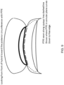
- FIG. 18 illustrates a longitudinal cross-sectional view of en exemplary prosthesis deployed in the mitral annulus in a heart with a non-dilated (A) and a dilated (B) mitral annulus.
- A non-dilated
- B dilated
- FIG. 18 illustrates a feature of an exemplary prosthesis whereby the first and second sets of atrial and ventricular radially and outwardly disposed fixation elements may act entirely to provide compression fixation of the tubular element of the prosthesis in the mitral annulus through force on the endocardium of the atrium and ventricle, respectively (A).
- first and second sets of atrial and ventricular radially and outwardly disposed fixation elements may contact each other in the plane of the mitral annulus for a portion of the circumference of the mitral annulus as well as providing compression fixation of the tubular element of the prosthesis in the mitral annulus through force on the endocardium of the atrium and ventricle laterally, respectively (B).
- FIG. 19 illustrates a cross-section through a non-dilated (A) mitral annulus and a dilated (B) mitral annulus with the exemplary prosthesis of FIG. 18 in place.
- FIG. 19 (A) reveals that the lateral wall of the tubular element of the exemplary prosthesis abuts the mitral annulus for a circumference of the mitral annulus except where the anterior mitral leaflet emanates from the anterior mitral annulus between the right and left commissures.
- FIG. 19 (A) reveals that the lateral wall of the tubular element of the exemplary prosthesis abuts the mitral annulus for a circumference of the mitral annulus except where the anterior mitral leaflet emanates from the anterior mitral annulus between the right and left commissures.
- first and second sets of atrial and ventricular radially and outwardly disposed fixation elements may contact each other in the plane of the mitral annulus between the mitral annulus and the tubular element of the device for less than the entire circumference of the mitral orifice ( 2 ), leaving the circumference of the mitral annulus subtending the anterior mitral valve leaflet free ( 1 ).
- Exemplary embodiments provide systems, devices and methods for repairing or replacing elements of the mitral valve.
- Exemplary elements of the valve prosthesis include the device frame, prosthetic posterior mitral leaflet equivalent and elements to prevent or reduce abnormal prolapse of the native anterior mitral leaflet during systole.
- Exemplary methods of implanting the valve prosthesis include direct open surgical placement, minimally invasive surgical placement either with or without the use of cardiopulmonary bypass, and totally catheter based implantation.
- Exemplary methods for maintaining the valve prosthesis in the preferred mitral annular location include external compression, compression following rail or suture guided implantation and seating with subsequent active or passive fixation of the valve prosthesis based upon the rail or suture guides.
- Exemplary embodiments on the frame of the valve prosthesis depicted in the Figures include a central element that can be inserted within the mitral valve annulus with elements (e.g., struts, loops and the like) above and below the central element to provide for fixation of the central element in the annulus.
- the prosthesis can be tubular or “D” shaped with the flat portion subtending the atrial side of the anterior annulus between the right and left fibrous trigones with the curved portion of the “D” to subtend the posterior annulus between the trigones.
- Either the anterior portion of the “D” shaped device, or the posterior portion of the “D” shaped device, or both sections can be distensible and therefore capable of shortening or lengthening to adjust variably to different size mitral annulae.
- the tubular element may be planar or may be shaped planar for a section of the tubular element but with an elevation of one section of the circumference of the tubular element that corresponds to the anterior (atrial) portion of the tubular element of the device.
- the advantage of such an asymmetrical shape can be that it simulates the natural “saddle” shape of the mitral valve orifice.
- This shape can allow for radial compression and seating of the valve prosthesis above the mitral annulus subjacent to the anterior mitral leaflet on the atrial side of the device.
- This exemplary shape can provide for unimpaired excursion of the anterior mitral leaflet to allow adequate opening and closure of the mitral valve orifice based on the movement of the anterior leaflet.
- the anterior circumference of the device can be flat or semicircular, while the remainder of the circumference can remain circular.
- the anterior section of the device may expand to match the distance between the right and left fibrous trigones of the native mitral annulus. Such a feature can allow one device to fit into differing size mitral annulae.
- the first set of radially and outwardly disposed fixation elements can abut the atrial endocardium above the mitral annulus, holding the tubular element of the device at or above the plane of the mitral annulus.
- the tubular element can be above the annulus.
- the second set of radially and outwardly disposed fixation elements can be configured to abut the ventricular endocardium along the posterior mitral annulus between the anterior and posterior mitral commissures to provide compression and hold the tubular element at or near the plane of the mitral annulus posteriorly.
- first set of fixation elements and second set of fixation elements can abut each other in the plane of the mitral annulus between the anterior and posterior mitral commissures along the posterior mitral annulus.
- This embodiment can provide a mechanism to utilize the prosthesis to reduce the orifice size of the mitral valve to that of the tubular element of the device.
- This feature can be used, for example, to treat patients with mitral regurgitation exclusively or partially related to native mitral annular dilatation in conjunction with other prosthesis elements described herein.
- An exemplary embodiment of the ventricular portion of the device can include an incomplete circumference designed to provide for compression against the left ventricular endocardium and fixation of the tubular element of the valve device at or above the mitral annulus. This shape and positioning of the valve device can permit unobstructed opening and closing motion of the anterior mitral leaflet. The ventricular posterior of the valve device would theoretically compress the posterior mitral leaflet against posterior left ventricular endocardium when fully deployed.
- An exemplary embodiment of the atrial section of the device can expand to coapt with the endocardium of the left atrium to provide for fixation of the tubular section of the valve device at or above the mitral annulus.
- the tubular or D-shaped element of the device can occupy the mitral annular plane, or can occupy the mitral annulus and extend into the left atrium and left ventricle for a desired distance.
- An exemplary method of fixation of the valve device can include compression or the radial force exerted on the left atrial endocardium, mitral annulus and left ventricular endocardium by the expanded and fully deployed valve device.
- the atrial section of the device adjacent to the anterior mitral annulus would be held in position by radial force and/or by two points of fixation at the fibrous trigones and/or other points along the circumference of the annulus.
- fixation of the valve device at the mitral annular level can be performed by active fixation.
- barbed arrows or other fasteners can extend radially and outwardly from the tubular element of the valve device to project into the anterior annulus or trigones once the device is deployed.
- hooks or other fasteners can extend radially from the ventricular side of the tubular element to directly engage the anterior annulus at the anterior and posterior commissures posterior to the trigones.
- barbed spears or hooks or other fasteners can extend radially and outwardly from either the ventricular or atrial fastening members during or after implantation.
- One embodiment of the device can include one or more inflatable chambers located on the outer circumference of the central tubular element of the device.
- the chambers can be filled with liquid or gas or semisolid material remotely or through directly connected tube(s) to cause the inflatable chambers to expand and occupy space between the external central (annular) plane of the device and the native mitral annulus.
- Such a device can help prevent periprosthetic leak, for example, in the setting of a calcified, irregularly shaped mitral annulus.
- some or all of the frame of the device can be composed of biological tissue and/or tissue permitting tissue ingrowth (e.g., ePTFE).
- tissue ingrowth e.g., ePTFE
- This composition of the device can allow for fixation of the device into the mitral annulus initially through compression with or without active fixation. Over time, the biological tissue would permit growth into the native annulus, left atrium and/or left ventricle where fixation based on compression would no longer be necessary.
- An exemplary embodiment of a valve device can include a covering of the central tubular element of the device to create an artificial posterior mitral leaflet connected by a variety of fixation techniques to the posterior circumference of the device.
- the covering can be of a variety of Artificial or biological tissue compatible types as disclosed elsewhere herein, for example.
- the covering, or prosthetic posterior mitral leaflet can either be attached in a fixed or stationary position, or loosely to provide for both an opening and a closing position.
- the covering can be composed of either a single or multiple covering pieces. The single or multiple covering pieces can be connected to the inside of the device in an annular plane along the posterior circumference of the device not occupied by the anterior mitral leaflet when the anterior mitral leaflet would be in a closed position.
- the single covering version of the device can have the covering connected to the ventricular fixation portion of the device at the incomplete margin, along the internal aspect of the ventricular fixation element toward the tubular element and then along the annular plane within the tubular element posteriorly.
- the coverings can be connected to the inner annular portion of the device as above, with sectional coverings held by connecting cords to the ventricular fixation element posteriorly along the base to prevent prolapse above the plane of the tubular element.
- the length and/or height of the artificial posterior covering of the device can be controlled before, during or after device implantation.
- two ends of one string can run under the posterior mitral covering along the edge to alter the tension and therefore the area of the mitral orifice covered by the posterior covering. Similar mechanisms can provide for altering the shape and circumference covered by the prosthetic posterior mitral leaflet.
- the single covering version can include a highly redundant posterior leaflet to treat a restrictive defect in the native anterior mitral leaflet. Also, this version can be used to treat anterior mitral leaflet prolapse by creating a large zone of coaptation in the left atrium.
- Another embodiment of the device can include one or more inflatable chambers (see adjacent rectangular chambers in lower portion of prosthesis in FIG. 15 ) located within the circumference of the device below the tubular element of the device between the ventricular skirt of the device and the one or more prosthetic posterior leaflet equivalents.
- These inflatable chambers can be filled with liquid or gas or semisolid material at the time of implantation or remotely or through directly connected tubes to advance or retract the prosthetic posterior leaflet. This permits improvement of coaptation between the native anterior mitral leaflet and the prosthetic posterior leaflet(s).
- one exemplary embodiment can include techniques such as those described in the PCT application incorporated by reference herein, which in some embodiments provides two or more suture guides affixed to the outer circumference of the tubular element of the device to allow for directed placement and/or proper positioning of the device, orientation and fixation, such as illustrated in FIGS. 4 A-E .
- These guides can be located, for example on the external circumference of the tubular element of the device.
- These suture guides can also be formed as holes or openings defined in the prosthesis frame or body, external rings, tubes or similar shapes.
- two guides can be positioned anteriorly to approximate the distance between the right and left fibrous trigones.
- the suture guides can be movable to dynamically fit the delivery and seating of the device to different anatomical sizes of mitral annulae.
- the device can include one or more such guides on the posterior external circumference of the device with or without such guides on the anterior aspect of the device. These too can be fixed in position or be adjustable to approximate the distance between sutures placed in the native mitral annulus by a variety of techniques and imaged by a variety of techniques.
- These guides can, if desired, be used in conjunction with a single suture, a loop of suture, and/or a rail of any material that could be fixed at an annular or periannular location to guide the device into location and possibly to fix the device in place.
- the suture guides can be used to drive the device into position in a beating heart. Once the device is delivered through the annulus, the ventricular portion of the device can be deployed to bring the ventricular skirt into coaptation with the endocardium of the left ventricle. This action can also incompletely deploy the atrial skirt of the device such that blood can immediately flow through the open central portion of the device, but without the user ever losing control of or being able to fully retrieve the device.
- the device can then be rotated to identify the best position of the prosthetic posterior mitral leaflet using a dynamic imaging study such as three-dimensional or two-dimensional echocardiography.
- the sutures or rails passed through the guides can then be tied and/or crimped and subsequently cut to fix the device in permanent position following full deployment.
- the device can include anterior-posterior and/or septal-lateral transversely directed “bars” or cords of biological or tissue compatible material such as PTFE or covered tantalum (e.g., see FIGS. 16 - 17 ) that spring into place upon deployment of the device at or above the annular plane to prevent anterior leaflet prolapse.
- bars biological or tissue compatible material
- These may also be flat straps of tissue compatible material or biological tissue that can rotate at their ends. These straps can rotate parallel to the direction of flow during diastole to avoid obstructing blood flow and then rotate flat during systole to increase the area of coverage of the potentially prolapsing anterior mitral leaflet.
- the valve device(s) described herein may be implanted surgically (on or off cardiopulmonary bypass) or as a minimally invasive surgical procedure.
- the device can also be implanted in one exemplary design as a fully catheter mounted device.
- the access to the mitral annulus can be, for example, through the left ventricular apex, through the free wall of the left atrium or through the left atrial septum.
- the implant method for such device(s) can allow for rotation under imaging to properly position the partially deployed device and prosthetic posterior leaflet equivalent in conjunction with transesophageal (2D or 3D) or fluoroscopically.
- the external circumference of the annular level of the device can be coated with a fixed or expandable coating or element that can serve to prevent periprosthetic leak by occupying space between the external annular level of the device and the native mitral annulus.
- the annulus can be rendered irregularly shaped and firm by virtue of calcification. This element of the prosthesis can occupy such spaces between the irregularly shaped native mitral annulus and the uniformly circumferential external wall of the device.
- the disclosure provides heart valve prosthesis that includes a tubular or “D”-shaped member configured for deployment in a heart valve annulus, first set of fastening mechanisms radially and outwardly disposed from the tubular or “D”-shaped member and configured to attach the valve prosthesis to cardiac tissue above the heart valve annulus, a second set of fastening mechanisms radially and outwardly disposed from the tubular or “D”-shaped member for less than the entire circumference of the tubular or “D”-shaped member and configured to attach the valve prosthesis to cardiac tissue below the heart valve annulus, and an incomplete covering/closure of the interior of the tubular or “D”-shaped member attached by any of various connectors to the inner circumference of the radially and outwardly disposed fastening mechanisms above, at or below the heart valve annulus.
- the first set of fastening mechanisms radially and outwardly disposed from the tubular or “D”-shaped member can be configured to attach the valve prosthesis to cardiac tissue above the heart valve annulus and can be interrupted for a section of the circumference where hooks, tines (and other connectors) can be disposed to attach the tubular or “D”-shaped member above the heart valve annulus.
- two hooks can extend radially outward from the exterior of the tubular of “D”-shaped member for attachment to the myocardium below the annulus to secure the tubular of “D”-shaped member above the annulus.
- the incomplete covering/closure of the interior of the tubular or “D”-shaped member can be a unitary panel or can be interrupted in one or more sections with attachments to the second set of fastening mechanisms radially and outwardly disposed from the tubular or “D”-shaped member to prevent displacement of the incomplete covering or closure above the highest point of the tubular or “D”-shaped member above the annulus.
- the incomplete covering/closure of the interior of the tubular or “D”-shaped member may be composed of biological tissue. If desired, the device can be completely or partially constructed of biological material.
- the incomplete covering/closure of the interior of the tubular or “D”-shaped member may be fixed or mobile.
- the position of the incomplete covering/closure of the interior of the tubular or “D”-shaped member can be variably controlled by sutures or one or more remotely inflatable chambers.
- two or more rings can be laterally disposed from the external circumference of the tubular or “D”-shaped member.
- the rings can freely move in the plane along the external circumference of the tubular or “D”-shaped member until the device is fully deployed.
- One or more fixed or mobile bars or straps of tissue compatible material may cross the internal area of the tubular or “D”-shaped member or the first set of fastening mechanisms radially and outwardly disposed from the tubular or “D”-shaped member.
- the external circumference of the tubular or “D”-shaped member can include an expandable material or covering and/or remotely inflatable chambers to adhere to an irregularly shaped valve annulus and can either automatically or controllably oppose and seal the space between the annulus and the device.
- the device can contain a remote monitor to measure blood flow, blood pressure, heart rate or heart rhythm and transmit the data to a user terminal that can be viewed by a surgeon, physician or operating room assistant.
Landscapes
- Health & Medical Sciences (AREA)
- Cardiology (AREA)
- Engineering & Computer Science (AREA)
- Biomedical Technology (AREA)
- Life Sciences & Earth Sciences (AREA)
- Veterinary Medicine (AREA)
- General Health & Medical Sciences (AREA)
- Heart & Thoracic Surgery (AREA)
- Public Health (AREA)
- Animal Behavior & Ethology (AREA)
- Oral & Maxillofacial Surgery (AREA)
- Transplantation (AREA)
- Vascular Medicine (AREA)
- Surgery (AREA)
- Rheumatology (AREA)
- Nuclear Medicine, Radiotherapy & Molecular Imaging (AREA)
- Medical Informatics (AREA)
- Molecular Biology (AREA)
- Prostheses (AREA)
Abstract
Description
Claims (20)
Priority Applications (2)
| Application Number | Priority Date | Filing Date | Title |
|---|---|---|---|
| US17/086,106 US12053378B2 (en) | 2012-11-07 | 2020-10-30 | Devices, systems and methods for repairing lumenal systems |
| US18/655,063 US20240285405A1 (en) | 2012-11-07 | 2024-05-03 | Devices, systems and methods for repairing lumenal systems |
Applications Claiming Priority (8)
| Application Number | Priority Date | Filing Date | Title |
|---|---|---|---|
| US201261723734P | 2012-11-07 | 2012-11-07 | |
| US14/074,517 US9549817B2 (en) | 2011-09-22 | 2013-11-07 | Devices, systems and methods for repairing lumenal systems |
| PCT/US2014/049629 WO2015020971A1 (en) | 2013-08-04 | 2014-08-04 | Devices, systems and methods for repairing lumenal systems |
| US14/453,478 US10449046B2 (en) | 2011-09-22 | 2014-08-06 | Devices, systems and methods for repairing lumenal systems |
| US15/413,017 US10398551B2 (en) | 2011-09-22 | 2017-01-23 | Devices, systems and methods for repairing lumenal systems |
| US16/400,020 US11839543B2 (en) | 2012-11-07 | 2019-04-30 | Devices, systems and methods for repairing lumenal systems |
| US16/557,171 US11357627B2 (en) | 2012-11-07 | 2019-08-30 | Devices, systems and methods for repairing lumenal systems |
| US17/086,106 US12053378B2 (en) | 2012-11-07 | 2020-10-30 | Devices, systems and methods for repairing lumenal systems |
Related Parent Applications (2)
| Application Number | Title | Priority Date | Filing Date |
|---|---|---|---|
| US16/400,020 Continuation-In-Part US11839543B2 (en) | 2012-11-07 | 2019-04-30 | Devices, systems and methods for repairing lumenal systems |
| US16/557,171 Continuation-In-Part US11357627B2 (en) | 2012-11-07 | 2019-08-30 | Devices, systems and methods for repairing lumenal systems |
Related Child Applications (1)
| Application Number | Title | Priority Date | Filing Date |
|---|---|---|---|
| US18/655,063 Continuation US20240285405A1 (en) | 2012-11-07 | 2024-05-03 | Devices, systems and methods for repairing lumenal systems |
Publications (2)
| Publication Number | Publication Date |
|---|---|
| US20210228354A1 US20210228354A1 (en) | 2021-07-29 |
| US12053378B2 true US12053378B2 (en) | 2024-08-06 |
Family
ID=76969619
Family Applications (1)
| Application Number | Title | Priority Date | Filing Date |
|---|---|---|---|
| US17/086,106 Active 2036-05-31 US12053378B2 (en) | 2012-11-07 | 2020-10-30 | Devices, systems and methods for repairing lumenal systems |
Country Status (1)
| Country | Link |
|---|---|
| US (1) | US12053378B2 (en) |
Cited By (1)
| Publication number | Priority date | Publication date | Assignee | Title |
|---|---|---|---|---|
| US20250366988A1 (en) * | 2024-05-29 | 2025-12-04 | Vesalius Cardiovascular Inc. | Heart valve repair apparatus |
Families Citing this family (11)
| Publication number | Priority date | Publication date | Assignee | Title |
|---|---|---|---|---|
| WO2006032051A2 (en) | 2004-09-14 | 2006-03-23 | Edwards Lifesciences Ag | Device and method for treatment of heart valve regurgitation |
| US20090276040A1 (en) | 2008-05-01 | 2009-11-05 | Edwards Lifesciences Corporation | Device and method for replacing mitral valve |
| EP2429455B8 (en) | 2009-04-29 | 2021-12-15 | Edwards Lifesciences Corporation | Apparatus for replacing a diseased cardiac valve |
| US8449599B2 (en) | 2009-12-04 | 2013-05-28 | Edwards Lifesciences Corporation | Prosthetic valve for replacing mitral valve |
| US12502276B2 (en) | 2011-05-16 | 2025-12-23 | Edwards Lifesciences Corporation | Inversion delivery device and method for a prosthesis |
| US9532870B2 (en) | 2014-06-06 | 2017-01-03 | Edwards Lifesciences Corporation | Prosthetic valve for replacing a mitral valve |
| EP3448316B1 (en) * | 2016-04-29 | 2023-03-29 | Medtronic Vascular Inc. | Prosthetic heart valve devices with tethered anchors |
| US10350062B2 (en) | 2016-07-21 | 2019-07-16 | Edwards Lifesciences Corporation | Replacement heart valve prosthesis |
| WO2019147846A2 (en) | 2018-01-25 | 2019-08-01 | Edwards Lifesciences Corporation | Delivery system for aided replacement valve recapture and repositioning post- deployment |
| EP3952790A1 (en) | 2019-04-12 | 2022-02-16 | W.L. Gore & Associates, Inc. | Valve with multi-part frame and associated resilient bridging features |
| AU2022377336A1 (en) | 2021-10-27 | 2024-04-11 | Edwards Lifesciences Corporation | System and method for crimping and loading a prosthetic heart valve |
Citations (139)
| Publication number | Priority date | Publication date | Assignee | Title |
|---|---|---|---|---|
| US4106129A (en) | 1976-01-09 | 1978-08-15 | American Hospital Supply Corporation | Supported bioprosthetic heart valve with compliant orifice ring |
| US4218783A (en) * | 1977-09-22 | 1980-08-26 | Dr. E. Fresenius, Chem.-Pharm. Industrie KG | Prosthetic closure element for the replacement of the mitral and tricuspid valve in the human heart |
| US4259753A (en) | 1979-03-16 | 1981-04-07 | Liotta Domingo S | Frame support for cardiac tissue valves |
| US4666442A (en) | 1984-03-03 | 1987-05-19 | Sorin Biomedica S.P.A. | Cardiac valve prosthesis with valve flaps of biological tissue |
| US4692164A (en) | 1986-03-06 | 1987-09-08 | Moskovskoe Vysshee Tekhnicheskoe Uchilische, Imeni N.E. Baumana | Bioprosthetic heart valve, methods and device for preparation thereof |
| US5411552A (en) | 1990-05-18 | 1995-05-02 | Andersen; Henning R. | Valve prothesis for implantation in the body and a catheter for implanting such valve prothesis |
| US5449384A (en) | 1992-09-28 | 1995-09-12 | Medtronic, Inc. | Dynamic annulus heart valve employing preserved porcine valve leaflets |
| US5606928A (en) | 1991-05-08 | 1997-03-04 | Nika Health Products Limited | Process and apparatus for the production of a heart valve prosthesis |
| US5788715A (en) | 1995-02-07 | 1998-08-04 | C.R. Bard, Inc. | Telescoping serial elastic band ligator |
| US5843167A (en) | 1993-04-22 | 1998-12-01 | C. R. Bard, Inc. | Method and apparatus for recapture of hooked endoprosthesis |
| US5861028A (en) | 1996-09-09 | 1999-01-19 | Shelhigh Inc | Natural tissue heart valve and stent prosthesis and method for making the same |
| US5895410A (en) | 1997-09-12 | 1999-04-20 | B. Braun Medical, Inc. | Introducer for an expandable vascular occlusion device |
| US5928281A (en) | 1997-03-27 | 1999-07-27 | Baxter International Inc. | Tissue heart valves |
| US6059769A (en) | 1998-10-02 | 2000-05-09 | Medtronic, Inc. | Medical catheter with grooved soft distal segment |
| US6106510A (en) | 1998-05-28 | 2000-08-22 | Medtronic, Inc. | Extruded guide catheter shaft with bump extrusion soft distal segment |
| US20010021872A1 (en) | 1999-12-31 | 2001-09-13 | Bailey Steven R. | Endoluminal cardiac and venous valve prostheses and methods of manufacture and delivery thereof |
| US20020032481A1 (en) | 2000-09-12 | 2002-03-14 | Shlomo Gabbay | Heart valve prosthesis and sutureless implantation of a heart valve prosthesis |
| US6419695B1 (en) | 2000-05-22 | 2002-07-16 | Shlomo Gabbay | Cardiac prosthesis for helping improve operation of a heart valve |
| US20020138138A1 (en) | 2001-03-23 | 2002-09-26 | Jibin Yang | Rolled minimally-invasive heart valves and methods of use |
| US20030055495A1 (en) | 2001-03-23 | 2003-03-20 | Pease Matthew L. | Rolled minimally-invasive heart valves and methods of manufacture |
| US20030065386A1 (en) | 2001-09-28 | 2003-04-03 | Weadock Kevin Shaun | Radially expandable endoprosthesis device with two-stage deployment |
| US20030097172A1 (en) | 2000-03-27 | 2003-05-22 | Ilan Shalev | Narrowing implant |
| US6599303B1 (en) | 1998-11-06 | 2003-07-29 | St. Jude Medical Atg, Inc. | Medical graft connector and methods of making and installing same |
| US6602271B2 (en) | 2000-05-24 | 2003-08-05 | Medtronic Ave, Inc. | Collapsible blood filter with optimal braid geometry |
| US20030199975A1 (en) * | 2000-05-22 | 2003-10-23 | Shlomo Gabbay | Low invasive implantable cardiac prosthesis and method for helping improve operation of a heart valve |
| US6716231B1 (en) | 1999-08-03 | 2004-04-06 | Nasser Rafiee | Distal protection device |
| US20040087998A1 (en) | 2002-08-29 | 2004-05-06 | Scimed Life Systems, Inc. | Device and method for treatment of a vascular defect |
| US20040127916A1 (en) | 1998-09-18 | 2004-07-01 | Aptus Endosystems, Inc. | Catheter-based fastener implantation apparatus and methods with implantation force resolution |
| US6790229B1 (en) | 1999-05-25 | 2004-09-14 | Eric Berreklouw | Fixing device, in particular for fixing to vascular wall tissue |
| US6797000B2 (en) | 1999-01-27 | 2004-09-28 | Carbomedics Inc. | Tri-composite, full root, stentless valve |
| US6800081B2 (en) | 1998-09-18 | 2004-10-05 | Aptus Endosystems, Inc. | Systems and methods for applying a suture within a blood vesel lumen |
| US20040260317A1 (en) | 2003-06-20 | 2004-12-23 | Elliot Bloom | Tensioning device, system, and method for treating mitral valve regurgitation |
| US20050038508A1 (en) | 2003-08-13 | 2005-02-17 | Shlomo Gabbay | Implantable cardiac prosthesis for mitigating prolapse of a heart valve |
| US20050038509A1 (en) * | 2003-08-14 | 2005-02-17 | Ashe Kassem Ali | Valve prosthesis including a prosthetic leaflet |
| US20050043790A1 (en) | 2001-07-04 | 2005-02-24 | Jacques Seguin | Kit enabling a prosthetic valve to be placed in a body enabling a prosthetic valve to be put into place in a duct in the body |
| US20050055082A1 (en) | 2001-10-04 | 2005-03-10 | Shmuel Ben Muvhar | Flow reducing implant |
| US6866677B2 (en) | 2001-04-03 | 2005-03-15 | Medtronic Ave, Inc. | Temporary intraluminal filter guidewire and methods of use |
| US6893459B1 (en) | 2000-09-20 | 2005-05-17 | Ample Medical, Inc. | Heart valve annulus device and method of using same |
| US20050137769A1 (en) | 2003-12-19 | 2005-06-23 | Toyota Jidosha Kabushiki Kaisha | Vehicle integrated control system |
| US6911036B2 (en) | 2001-04-03 | 2005-06-28 | Medtronic Vascular, Inc. | Guidewire apparatus for temporary distal embolic protection |
| US20050143809A1 (en) | 2003-12-23 | 2005-06-30 | Sadra Medical A Delaware Corporation | Methods and apparatus for endovascularly replacing a heart valve |
| US20050177180A1 (en) | 2001-11-28 | 2005-08-11 | Aptus Endosystems, Inc. | Devices, systems, and methods for supporting tissue and/or structures within a hollow body organ |
| US6960217B2 (en) | 2001-11-28 | 2005-11-01 | Aptus Endosystems, Inc. | Endovascular aneurysm repair system |
| US20050288706A1 (en) | 2004-05-07 | 2005-12-29 | Nmt Medical, Inc. | Inflatable occluder |
| US20060085012A1 (en) | 2004-09-28 | 2006-04-20 | Medtronic Vascular, Inc. | Torquing device delivered over a guidewire to rotate a medical fastener |
| US7044958B2 (en) | 2001-04-03 | 2006-05-16 | Medtronic Vascular, Inc. | Temporary device for capturing embolic material |
| US20060106449A1 (en) | 2002-08-08 | 2006-05-18 | Neovasc Medical Ltd. | Flow reducing implant |
| US20060106450A1 (en) | 2002-08-08 | 2006-05-18 | Neovasc Medical Ltd. | Geometric flow regulator |
| US7066946B2 (en) | 2001-04-03 | 2006-06-27 | Medtronic Vascular, Inc | Temporary intraluminal filter guidewire |
| US20060259135A1 (en) | 2005-04-20 | 2006-11-16 | The Cleveland Clinic Foundation | Apparatus and method for replacing a cardiac valve |
| US20070016288A1 (en) | 2005-07-13 | 2007-01-18 | Gurskis Donnell W | Two-piece percutaneous prosthetic heart valves and methods for making and using them |
| US20070043435A1 (en) | 1999-11-17 | 2007-02-22 | Jacques Seguin | Non-cylindrical prosthetic valve system for transluminal delivery |
| US7189259B2 (en) | 2002-11-26 | 2007-03-13 | Clemson University | Tissue material and process for bioprosthesis |
| US20070067029A1 (en) | 2005-09-16 | 2007-03-22 | Shlomo Gabbay | Support apparatus to facilitate implantation of cardiac prosthesis |
| US7195641B2 (en) | 1999-11-19 | 2007-03-27 | Advanced Bio Prosthetic Surfaces, Ltd. | Valvular prostheses having metal or pseudometallic construction and methods of manufacture |
| US7201772B2 (en) | 2003-07-08 | 2007-04-10 | Ventor Technologies, Ltd. | Fluid flow prosthetic device |
| WO2007121314A2 (en) | 2006-04-12 | 2007-10-25 | Medtronic Vascular, Inc. | Annuloplasty device having a helical anchor and methods for its use |
| US20070250160A1 (en) | 2006-04-21 | 2007-10-25 | Medtronic Vascular, Inc. | Device, system, and method for treating cardiac valve regurgitation |
| US20070260305A1 (en) | 2006-04-29 | 2007-11-08 | Drews Michael J | Guide shields for multiple component prosthetic heart valve assemblies and apparatus and methods for using them |
| US7294135B2 (en) | 2003-03-20 | 2007-11-13 | Medtronic Vascular, Inc | Control handle for intraluminal devices |
| US20070288089A1 (en) | 2006-04-29 | 2007-12-13 | Gurskis Donnell W | Multiple component prosthetic heart valve assemblies and methods for delivering them |
| US20070293942A1 (en) | 2006-06-16 | 2007-12-20 | Daryush Mirzaee | Prosthetic valve and deployment method |
| US20080021537A1 (en) | 2000-03-27 | 2008-01-24 | Neovasc Medical Ltd. | Varying diameter vascular implant and balloon |
| US20080065191A1 (en) | 2001-11-28 | 2008-03-13 | Aptus Endosystems, Inc. | Prosthesis systems and methods |
| US20080071369A1 (en) | 2006-09-19 | 2008-03-20 | Yosi Tuval | Valve fixation member having engagement arms |
| US20080077234A1 (en) | 2004-09-07 | 2008-03-27 | Styrc Mikolaj W | Valve Prosthesis |
| US20080125860A1 (en) | 2002-11-15 | 2008-05-29 | Webler William E | Valve aptation assist device |
| US7399315B2 (en) | 2003-03-18 | 2008-07-15 | Edwards Lifescience Corporation | Minimally-invasive heart valve with cusp positioners |
| US20080208328A1 (en) | 2007-02-23 | 2008-08-28 | Endovalve, Inc. | Systems and Methods For Placement of Valve Prosthesis System |
| US20080221672A1 (en) | 2007-02-23 | 2008-09-11 | Endovalve, Inc. | Mitral Valve System |
| US7425219B2 (en) | 2003-10-10 | 2008-09-16 | Arshad Quadri | System and method for endoluminal grafting of bifurcated and branched vessels |
| US7445631B2 (en) | 2003-12-23 | 2008-11-04 | Sadra Medical, Inc. | Methods and apparatus for endovascularly replacing a patient's heart valve |
| US20080281411A1 (en) | 2004-03-26 | 2008-11-13 | Eric Berreklouw | Assembly Comprising A Ring For Attachment In A Passage Surrounded By Body Tissue As Well As An Applicator For Fitting The Ring In The Passage |
| US20090005863A1 (en) | 2006-02-16 | 2009-01-01 | Goetz Wolfgang | Minimally invasive heart valve replacement |
| US7481838B2 (en) | 1999-01-26 | 2009-01-27 | Edwards Lifesciences Corporation | Flexible heart valve and associated connecting band |
| US20090062841A1 (en) | 2004-03-19 | 2009-03-05 | Aga Medical Corporation | Device for occluding vascular defects |
| US20090149949A1 (en) | 2004-12-15 | 2009-06-11 | Mednua Limited | Medical device suitable for use in treatment of a valve |
| US20090270976A1 (en) | 2008-04-24 | 2009-10-29 | Medtronic Vascular, Inc. | Stent Graft Fixation System and Method of Use |
| US20090270966A1 (en) | 2008-04-24 | 2009-10-29 | Medtronic Vascular, Inc. | Stent Graft System and Method of Use |
| US20090306768A1 (en) | 2006-07-28 | 2009-12-10 | Cardiaq Valve Technologies, Inc. | Percutaneous valve prosthesis and system and method for implanting same |
| US20090319038A1 (en) | 2008-06-05 | 2009-12-24 | Arbor Surgical Technologies, Inc. | Connection systems for two piece prosthetic heart valve assemblies and methods for making and using them |
| US7655040B2 (en) | 2003-11-12 | 2010-02-02 | Medtronic Vascular, Inc. | Cardiac valve annulus reduction system |
| US20100036479A1 (en) | 2008-04-23 | 2010-02-11 | Medtronic, Inc. | Stented Heart Valve Devices |
| US7682352B2 (en) | 2004-09-28 | 2010-03-23 | Medtronic Vascular, Inc. | Catheter with curved distal section having reinforcing strip and method of making same |
| US20100082094A1 (en) | 2008-09-29 | 2010-04-01 | Arshad Quadri | Heart valve |
| US7699892B2 (en) | 2006-04-12 | 2010-04-20 | Medtronic Vascular, Inc. | Minimally invasive procedure for implanting an annuloplasty device |
| US20100100167A1 (en) | 2008-10-17 | 2010-04-22 | Georg Bortlein | Delivery system for deployment of medical devices |
| US7716801B2 (en) | 2003-11-24 | 2010-05-18 | Medtronic Vascular, Inc. | Low-profile distal protection device |
| US20100174363A1 (en) | 2009-01-07 | 2010-07-08 | Endovalve, Inc. | One Piece Prosthetic Valve Support Structure and Related Assemblies |
| US20100179649A1 (en) | 2009-01-12 | 2010-07-15 | Valve Medical Ltd. | Method and apparatus for fine adjustment of a percutaneous valve structure |
| US20100179648A1 (en) | 2009-01-12 | 2010-07-15 | Valve Medical Ltd. | System and method for placing a percutaneous valve device |
| US20100185275A1 (en) | 2009-01-12 | 2010-07-22 | Valve Medical Ltd. | Modular percutaneous valve structure and delivery method |
| US20100249923A1 (en) | 2007-09-28 | 2010-09-30 | St Jude Medical Inc. | Collapsible/expandable prosthetic heart valves with native calcified leaflet retention features |
| US7806919B2 (en) | 2008-04-01 | 2010-10-05 | Medtronic Vascular, Inc. | Double-walled stent system |
| US7806917B2 (en) | 2007-04-17 | 2010-10-05 | Medtronic Vascular, Inc. | Stent graft fixation system and method |
| US20100262232A1 (en) | 2009-04-10 | 2010-10-14 | Lon Southerland Annest | Implantable scaffolding containing an orifice for use with a prosthetic or bio-prosthetic valve |
| US20100280606A1 (en) | 2009-03-17 | 2010-11-04 | Biomedxl | Heart valve prosthesis with collapsible valve and method of delivery thereof |
| US20100298931A1 (en) | 2009-04-15 | 2010-11-25 | Arshad Quadri | Vascular implant and delivery system |
| RU100718U1 (en) | 2010-07-08 | 2010-12-27 | Учреждение Российской академии медицинских наук Научный центр сердечно-сосудистой хирургии имени А.Н. Бакулева РАМН | HEART VALVE BIOPROTHESIS |
| US20110112632A1 (en) | 2009-02-25 | 2011-05-12 | Edwards Lifesciences Corporation | Method of implanting a prosthetic valve in a mitral valve with pulmonary vein anchoring |
| US7955384B2 (en) | 2003-11-12 | 2011-06-07 | Medtronic Vascular, Inc. | Coronary sinus approach for repair of mitral valve regurgitation |
| US20110172784A1 (en) | 2010-01-12 | 2011-07-14 | Valve Medical Ltd. | Self-assembling modular percutaneous valve and methods of folding, assembly and delivery |
| US7998188B2 (en) | 2003-04-28 | 2011-08-16 | Kips Bay Medical, Inc. | Compliant blood vessel graft |
| US8002825B2 (en) | 1996-12-31 | 2011-08-23 | Edwards Lifesciences Pvt, Inc. | Implantable prosthetic valve for treating aortic stenosis |
| US20110282438A1 (en) | 2006-03-10 | 2011-11-17 | Medtronic, Inc. | Valve Introducers And Methods For Making And Using Them |
| US8062355B2 (en) | 2005-11-04 | 2011-11-22 | Jenavalve Technology, Inc. | Self-expandable medical instrument for treating defects in a patient's heart |
| US20110313515A1 (en) | 2010-06-21 | 2011-12-22 | Arshad Quadri | Replacement heart valve |
| US20110319990A1 (en) | 2000-09-20 | 2011-12-29 | Mvrx, Inc. | Devices, systems, and methods for supplementing, repairing or replacing a native heart valve leaflet |
| US20110319988A1 (en) | 2009-12-08 | 2011-12-29 | Avalon Medical, Ltd. | Device and System for Transcatheter Mitral Valve Replacement |
| US20110319989A1 (en) | 2010-05-05 | 2011-12-29 | Neovasc, Inc. | Transcatheter mitral valve prosthesis |
| US8092524B2 (en) | 2004-02-05 | 2012-01-10 | Children's Medical Center Corporation | Transcatheter delivery of a replacement heart valve |
| US8092518B2 (en) | 2000-04-06 | 2012-01-10 | Edwards Lifesciences Corporation | Methods of implanting two-part heart valves |
| US8092520B2 (en) | 2005-11-10 | 2012-01-10 | CardiAQ Technologies, Inc. | Vascular prosthesis connecting stent |
| US20120022639A1 (en) | 2010-07-21 | 2012-01-26 | Hacohen Gil | Guide wires with commissural anchors to advance a prosthetic valve |
| EP2412397A1 (en) | 2006-10-18 | 2012-02-01 | Guided Delivery Systems, Inc. | Catheter for implant deployment |
| US20120059450A1 (en) | 2003-07-21 | 2012-03-08 | Chiang Andrew L | Prosthesis delivery systems and methods |
| US20120078353A1 (en) | 2010-09-23 | 2012-03-29 | Cardiaq Valve Technologies, Inc. | Replacement heart valves, delivery devices and methods |
| US20120078360A1 (en) | 2010-09-23 | 2012-03-29 | Nasser Rafiee | Prosthetic devices, systems and methods for replacing heart valves |
| WO2012061809A2 (en) | 2010-11-06 | 2012-05-10 | Mehr Medical Llc | Methods and systems for delivering prostheses using rail techniques |
| US20120150290A1 (en) * | 2010-11-12 | 2012-06-14 | Shlomo Gabbay | Beating heart buttress and implantation method to prevent prolapse of a heart valve |
| US20120179086A1 (en) | 2009-09-11 | 2012-07-12 | Peter Shank | Anchors with open heads |
| US8226710B2 (en) | 2005-05-13 | 2012-07-24 | Medtronic Corevalve, Inc. | Heart valve prosthesis and methods of manufacture and use |
| US20120215303A1 (en) | 2009-09-29 | 2012-08-23 | Cardiaq Valve Technologies, Inc. | Replacement heart valve and method |
| US8308798B2 (en) | 2008-12-19 | 2012-11-13 | Edwards Lifesciences Corporation | Quick-connect prosthetic heart valve and methods |
| US20120316642A1 (en) | 2009-12-30 | 2012-12-13 | Microport Medical (Shanghai) Co., Ltd | Invasive cardiac valve |
| US20120323316A1 (en) | 2009-12-04 | 2012-12-20 | Edwards Lifesciences Corporation | Prosthetic apparatus for implantation at mitral valve |
| US8337541B2 (en) | 2008-10-01 | 2012-12-25 | Cardiaq Valve Technologies, Inc. | Delivery system for vascular implant |
| US8353955B2 (en) | 2009-07-10 | 2013-01-15 | Cormove | Prosthetic implant |
| US8353954B2 (en) | 2006-12-19 | 2013-01-15 | St. Jude Medical, Inc. | Prosthetic heart valve including stent structure and tissue leaflets, and related methods |
| WO2013131069A1 (en) | 2012-03-02 | 2013-09-06 | Mehr Medical Llc | Prostheses |
| US20140018906A1 (en) | 2010-09-23 | 2014-01-16 | Nasser Rafiee | Methods and systems for delivering prostheses using rail techniques |
| US20140039083A1 (en) | 2011-04-26 | 2014-02-06 | 3M Innovative Properties Company | Pressure-sensitive adhesives with mixed photocrosslinking system |
| US20140067054A1 (en) | 2012-09-06 | 2014-03-06 | Edwards Lifesciences Corporation | Heart Valve Sealing Devices |
| US20140128965A1 (en) | 2011-09-22 | 2014-05-08 | Nasser Rafiee | Devices, systems and methods for repairing lumenal systems |
| US20140163668A1 (en) | 2010-09-23 | 2014-06-12 | Nasser Rafiee | Methods and systems for delivering prostheses using rail techniques |
| US20140324164A1 (en) | 2011-08-05 | 2014-10-30 | Mitraltech Ltd. | Techniques for percutaneous mitral valve replacement and sealing |
| US20140343669A1 (en) | 2013-04-04 | 2014-11-20 | Neovasc Tiara Inc. | Methods and apparatus for delivering a prosthetic valve to a beating heart |
| US20140379074A1 (en) | 2012-01-31 | 2014-12-25 | Mitral Valve Technologies Sa | Mitral valve docking devices, systems and methods |
| WO2015148821A1 (en) | 2014-03-27 | 2015-10-01 | Nasser Rafiee | Devices and methods for closure of transvascular or transcameral access ports |
-
2020
- 2020-10-30 US US17/086,106 patent/US12053378B2/en active Active
Patent Citations (166)
| Publication number | Priority date | Publication date | Assignee | Title |
|---|---|---|---|---|
| US4106129A (en) | 1976-01-09 | 1978-08-15 | American Hospital Supply Corporation | Supported bioprosthetic heart valve with compliant orifice ring |
| US4218783A (en) * | 1977-09-22 | 1980-08-26 | Dr. E. Fresenius, Chem.-Pharm. Industrie KG | Prosthetic closure element for the replacement of the mitral and tricuspid valve in the human heart |
| US4259753A (en) | 1979-03-16 | 1981-04-07 | Liotta Domingo S | Frame support for cardiac tissue valves |
| US4666442A (en) | 1984-03-03 | 1987-05-19 | Sorin Biomedica S.P.A. | Cardiac valve prosthesis with valve flaps of biological tissue |
| US4692164A (en) | 1986-03-06 | 1987-09-08 | Moskovskoe Vysshee Tekhnicheskoe Uchilische, Imeni N.E. Baumana | Bioprosthetic heart valve, methods and device for preparation thereof |
| US5411552A (en) | 1990-05-18 | 1995-05-02 | Andersen; Henning R. | Valve prothesis for implantation in the body and a catheter for implanting such valve prothesis |
| US5606928A (en) | 1991-05-08 | 1997-03-04 | Nika Health Products Limited | Process and apparatus for the production of a heart valve prosthesis |
| US5449384A (en) | 1992-09-28 | 1995-09-12 | Medtronic, Inc. | Dynamic annulus heart valve employing preserved porcine valve leaflets |
| US5843167A (en) | 1993-04-22 | 1998-12-01 | C. R. Bard, Inc. | Method and apparatus for recapture of hooked endoprosthesis |
| US5788715A (en) | 1995-02-07 | 1998-08-04 | C.R. Bard, Inc. | Telescoping serial elastic band ligator |
| US5861028A (en) | 1996-09-09 | 1999-01-19 | Shelhigh Inc | Natural tissue heart valve and stent prosthesis and method for making the same |
| US8002825B2 (en) | 1996-12-31 | 2011-08-23 | Edwards Lifesciences Pvt, Inc. | Implantable prosthetic valve for treating aortic stenosis |
| US5928281A (en) | 1997-03-27 | 1999-07-27 | Baxter International Inc. | Tissue heart valves |
| US5895410A (en) | 1997-09-12 | 1999-04-20 | B. Braun Medical, Inc. | Introducer for an expandable vascular occlusion device |
| US6106510A (en) | 1998-05-28 | 2000-08-22 | Medtronic, Inc. | Extruded guide catheter shaft with bump extrusion soft distal segment |
| US20040127916A1 (en) | 1998-09-18 | 2004-07-01 | Aptus Endosystems, Inc. | Catheter-based fastener implantation apparatus and methods with implantation force resolution |
| US7491232B2 (en) | 1998-09-18 | 2009-02-17 | Aptus Endosystems, Inc. | Catheter-based fastener implantation apparatus and methods with implantation force resolution |
| US6800081B2 (en) | 1998-09-18 | 2004-10-05 | Aptus Endosystems, Inc. | Systems and methods for applying a suture within a blood vesel lumen |
| US6375774B1 (en) | 1998-10-02 | 2002-04-23 | Medtronic, Inc. | Method of making a medical catheter with grooved soft distal segment |
| US6059769A (en) | 1998-10-02 | 2000-05-09 | Medtronic, Inc. | Medical catheter with grooved soft distal segment |
| US6599303B1 (en) | 1998-11-06 | 2003-07-29 | St. Jude Medical Atg, Inc. | Medical graft connector and methods of making and installing same |
| US7481838B2 (en) | 1999-01-26 | 2009-01-27 | Edwards Lifesciences Corporation | Flexible heart valve and associated connecting band |
| US6797000B2 (en) | 1999-01-27 | 2004-09-28 | Carbomedics Inc. | Tri-composite, full root, stentless valve |
| US7524330B2 (en) | 1999-05-25 | 2009-04-28 | Eric Berreklouw | Fixing device, in particular for fixing to vascular wall tissue |
| US6790229B1 (en) | 1999-05-25 | 2004-09-14 | Eric Berreklouw | Fixing device, in particular for fixing to vascular wall tissue |
| US6716231B1 (en) | 1999-08-03 | 2004-04-06 | Nasser Rafiee | Distal protection device |
| US20070043435A1 (en) | 1999-11-17 | 2007-02-22 | Jacques Seguin | Non-cylindrical prosthetic valve system for transluminal delivery |
| US7195641B2 (en) | 1999-11-19 | 2007-03-27 | Advanced Bio Prosthetic Surfaces, Ltd. | Valvular prostheses having metal or pseudometallic construction and methods of manufacture |
| US7799069B2 (en) | 1999-12-31 | 2010-09-21 | Abps Venture One, Ltd. | Endoluminal cardiac and venous valve prostheses and methods of manufacture and delivery thereof |
| US20010021872A1 (en) | 1999-12-31 | 2001-09-13 | Bailey Steven R. | Endoluminal cardiac and venous valve prostheses and methods of manufacture and delivery thereof |
| US20080021537A1 (en) | 2000-03-27 | 2008-01-24 | Neovasc Medical Ltd. | Varying diameter vascular implant and balloon |
| US20030097172A1 (en) | 2000-03-27 | 2003-05-22 | Ilan Shalev | Narrowing implant |
| US6953476B1 (en) | 2000-03-27 | 2005-10-11 | Neovasc Medical Ltd. | Device and method for treating ischemic heart disease |
| US8092518B2 (en) | 2000-04-06 | 2012-01-10 | Edwards Lifesciences Corporation | Methods of implanting two-part heart valves |
| US6419695B1 (en) | 2000-05-22 | 2002-07-16 | Shlomo Gabbay | Cardiac prosthesis for helping improve operation of a heart valve |
| US20030199975A1 (en) * | 2000-05-22 | 2003-10-23 | Shlomo Gabbay | Low invasive implantable cardiac prosthesis and method for helping improve operation of a heart valve |
| US6869444B2 (en) * | 2000-05-22 | 2005-03-22 | Shlomo Gabbay | Low invasive implantable cardiac prosthesis and method for helping improve operation of a heart valve |
| US6602271B2 (en) | 2000-05-24 | 2003-08-05 | Medtronic Ave, Inc. | Collapsible blood filter with optimal braid geometry |
| US20020032481A1 (en) | 2000-09-12 | 2002-03-14 | Shlomo Gabbay | Heart valve prosthesis and sutureless implantation of a heart valve prosthesis |
| US20110319990A1 (en) | 2000-09-20 | 2011-12-29 | Mvrx, Inc. | Devices, systems, and methods for supplementing, repairing or replacing a native heart valve leaflet |
| US6893459B1 (en) | 2000-09-20 | 2005-05-17 | Ample Medical, Inc. | Heart valve annulus device and method of using same |
| US20070255398A1 (en) | 2001-03-23 | 2007-11-01 | Jibin Yang | Two-part expandable heart valve |
| US20060173537A1 (en) | 2001-03-23 | 2006-08-03 | Jibin Yang | Rolled minimally invasive heart valves |
| US20020138138A1 (en) | 2001-03-23 | 2002-09-26 | Jibin Yang | Rolled minimally-invasive heart valves and methods of use |
| US20030055495A1 (en) | 2001-03-23 | 2003-03-20 | Pease Matthew L. | Rolled minimally-invasive heart valves and methods of manufacture |
| US6733525B2 (en) | 2001-03-23 | 2004-05-11 | Edwards Lifesciences Corporation | Rolled minimally-invasive heart valves and methods of use |
| US7947072B2 (en) | 2001-03-23 | 2011-05-24 | Edwards Lifesciences Corporation | Two-part expandable heart valve |
| US20110137409A1 (en) | 2001-03-23 | 2011-06-09 | Edwards Lifesciences Corporation | Prosthetic heart valve having flared outflow section |
| US7066946B2 (en) | 2001-04-03 | 2006-06-27 | Medtronic Vascular, Inc | Temporary intraluminal filter guidewire |
| US7044958B2 (en) | 2001-04-03 | 2006-05-16 | Medtronic Vascular, Inc. | Temporary device for capturing embolic material |
| US6911036B2 (en) | 2001-04-03 | 2005-06-28 | Medtronic Vascular, Inc. | Guidewire apparatus for temporary distal embolic protection |
| US6866677B2 (en) | 2001-04-03 | 2005-03-15 | Medtronic Ave, Inc. | Temporary intraluminal filter guidewire and methods of use |
| US20050043790A1 (en) | 2001-07-04 | 2005-02-24 | Jacques Seguin | Kit enabling a prosthetic valve to be placed in a body enabling a prosthetic valve to be put into place in a duct in the body |
| US7780726B2 (en) | 2001-07-04 | 2010-08-24 | Medtronic, Inc. | Assembly for placing a prosthetic valve in a duct in the body |
| US20030065386A1 (en) | 2001-09-28 | 2003-04-03 | Weadock Kevin Shaun | Radially expandable endoprosthesis device with two-stage deployment |
| US20050055082A1 (en) | 2001-10-04 | 2005-03-10 | Shmuel Ben Muvhar | Flow reducing implant |
| US20050177180A1 (en) | 2001-11-28 | 2005-08-11 | Aptus Endosystems, Inc. | Devices, systems, and methods for supporting tissue and/or structures within a hollow body organ |
| US6960217B2 (en) | 2001-11-28 | 2005-11-01 | Aptus Endosystems, Inc. | Endovascular aneurysm repair system |
| US20080065191A1 (en) | 2001-11-28 | 2008-03-13 | Aptus Endosystems, Inc. | Prosthesis systems and methods |
| US20060106450A1 (en) | 2002-08-08 | 2006-05-18 | Neovasc Medical Ltd. | Geometric flow regulator |
| US20060106449A1 (en) | 2002-08-08 | 2006-05-18 | Neovasc Medical Ltd. | Flow reducing implant |
| US20040087998A1 (en) | 2002-08-29 | 2004-05-06 | Scimed Life Systems, Inc. | Device and method for treatment of a vascular defect |
| US20080125860A1 (en) | 2002-11-15 | 2008-05-29 | Webler William E | Valve aptation assist device |
| US7189259B2 (en) | 2002-11-26 | 2007-03-13 | Clemson University | Tissue material and process for bioprosthesis |
| US7753840B2 (en) | 2002-11-26 | 2010-07-13 | Clemson University | Tissue material process for forming bioprosthesis |
| US7399315B2 (en) | 2003-03-18 | 2008-07-15 | Edwards Lifescience Corporation | Minimally-invasive heart valve with cusp positioners |
| US7294135B2 (en) | 2003-03-20 | 2007-11-13 | Medtronic Vascular, Inc | Control handle for intraluminal devices |
| US7998188B2 (en) | 2003-04-28 | 2011-08-16 | Kips Bay Medical, Inc. | Compliant blood vessel graft |
| US20040260317A1 (en) | 2003-06-20 | 2004-12-23 | Elliot Bloom | Tensioning device, system, and method for treating mitral valve regurgitation |
| US7316706B2 (en) | 2003-06-20 | 2008-01-08 | Medtronic Vascular, Inc. | Tensioning device, system, and method for treating mitral valve regurgitation |
| US7442204B2 (en) | 2003-07-08 | 2008-10-28 | Ventor Technologies, Ltd. | Fluid flow prosthetic device |
| US7201772B2 (en) | 2003-07-08 | 2007-04-10 | Ventor Technologies, Ltd. | Fluid flow prosthetic device |
| US20120059450A1 (en) | 2003-07-21 | 2012-03-08 | Chiang Andrew L | Prosthesis delivery systems and methods |
| US20050038508A1 (en) | 2003-08-13 | 2005-02-17 | Shlomo Gabbay | Implantable cardiac prosthesis for mitigating prolapse of a heart valve |
| US20050038509A1 (en) * | 2003-08-14 | 2005-02-17 | Ashe Kassem Ali | Valve prosthesis including a prosthetic leaflet |
| US7425219B2 (en) | 2003-10-10 | 2008-09-16 | Arshad Quadri | System and method for endoluminal grafting of bifurcated and branched vessels |
| US7955384B2 (en) | 2003-11-12 | 2011-06-07 | Medtronic Vascular, Inc. | Coronary sinus approach for repair of mitral valve regurgitation |
| US7655040B2 (en) | 2003-11-12 | 2010-02-02 | Medtronic Vascular, Inc. | Cardiac valve annulus reduction system |
| US7716801B2 (en) | 2003-11-24 | 2010-05-18 | Medtronic Vascular, Inc. | Low-profile distal protection device |
| US20050137769A1 (en) | 2003-12-19 | 2005-06-23 | Toyota Jidosha Kabushiki Kaisha | Vehicle integrated control system |
| US7445631B2 (en) | 2003-12-23 | 2008-11-04 | Sadra Medical, Inc. | Methods and apparatus for endovascularly replacing a patient's heart valve |
| US20050143809A1 (en) | 2003-12-23 | 2005-06-30 | Sadra Medical A Delaware Corporation | Methods and apparatus for endovascularly replacing a heart valve |
| US8092524B2 (en) | 2004-02-05 | 2012-01-10 | Children's Medical Center Corporation | Transcatheter delivery of a replacement heart valve |
| US20090062841A1 (en) | 2004-03-19 | 2009-03-05 | Aga Medical Corporation | Device for occluding vascular defects |
| US20080281411A1 (en) | 2004-03-26 | 2008-11-13 | Eric Berreklouw | Assembly Comprising A Ring For Attachment In A Passage Surrounded By Body Tissue As Well As An Applicator For Fitting The Ring In The Passage |
| US20050288706A1 (en) | 2004-05-07 | 2005-12-29 | Nmt Medical, Inc. | Inflatable occluder |
| US20080077234A1 (en) | 2004-09-07 | 2008-03-27 | Styrc Mikolaj W | Valve Prosthesis |
| US20060085012A1 (en) | 2004-09-28 | 2006-04-20 | Medtronic Vascular, Inc. | Torquing device delivered over a guidewire to rotate a medical fastener |
| US7682352B2 (en) | 2004-09-28 | 2010-03-23 | Medtronic Vascular, Inc. | Catheter with curved distal section having reinforcing strip and method of making same |
| US20090149949A1 (en) | 2004-12-15 | 2009-06-11 | Mednua Limited | Medical device suitable for use in treatment of a valve |
| US20060259135A1 (en) | 2005-04-20 | 2006-11-16 | The Cleveland Clinic Foundation | Apparatus and method for replacing a cardiac valve |
| US8226710B2 (en) | 2005-05-13 | 2012-07-24 | Medtronic Corevalve, Inc. | Heart valve prosthesis and methods of manufacture and use |
| US20070016288A1 (en) | 2005-07-13 | 2007-01-18 | Gurskis Donnell W | Two-piece percutaneous prosthetic heart valves and methods for making and using them |
| US20070067029A1 (en) | 2005-09-16 | 2007-03-22 | Shlomo Gabbay | Support apparatus to facilitate implantation of cardiac prosthesis |
| US8062355B2 (en) | 2005-11-04 | 2011-11-22 | Jenavalve Technology, Inc. | Self-expandable medical instrument for treating defects in a patient's heart |
| US8092520B2 (en) | 2005-11-10 | 2012-01-10 | CardiAQ Technologies, Inc. | Vascular prosthesis connecting stent |
| US20090005863A1 (en) | 2006-02-16 | 2009-01-01 | Goetz Wolfgang | Minimally invasive heart valve replacement |
| US20110282438A1 (en) | 2006-03-10 | 2011-11-17 | Medtronic, Inc. | Valve Introducers And Methods For Making And Using Them |
| WO2007121314A2 (en) | 2006-04-12 | 2007-10-25 | Medtronic Vascular, Inc. | Annuloplasty device having a helical anchor and methods for its use |
| US7699892B2 (en) | 2006-04-12 | 2010-04-20 | Medtronic Vascular, Inc. | Minimally invasive procedure for implanting an annuloplasty device |
| US20070250160A1 (en) | 2006-04-21 | 2007-10-25 | Medtronic Vascular, Inc. | Device, system, and method for treating cardiac valve regurgitation |
| US7442207B2 (en) | 2006-04-21 | 2008-10-28 | Medtronic Vascular, Inc. | Device, system, and method for treating cardiac valve regurgitation |
| US20070260305A1 (en) | 2006-04-29 | 2007-11-08 | Drews Michael J | Guide shields for multiple component prosthetic heart valve assemblies and apparatus and methods for using them |
| US20070288089A1 (en) | 2006-04-29 | 2007-12-13 | Gurskis Donnell W | Multiple component prosthetic heart valve assemblies and methods for delivering them |
| US20070293942A1 (en) | 2006-06-16 | 2007-12-20 | Daryush Mirzaee | Prosthetic valve and deployment method |
| US20090306768A1 (en) | 2006-07-28 | 2009-12-10 | Cardiaq Valve Technologies, Inc. | Percutaneous valve prosthesis and system and method for implanting same |
| US20080071369A1 (en) | 2006-09-19 | 2008-03-20 | Yosi Tuval | Valve fixation member having engagement arms |
| US8348996B2 (en) | 2006-09-19 | 2013-01-08 | Medtronic Ventor Technologies Ltd. | Valve prosthesis implantation techniques |
| US8052750B2 (en) | 2006-09-19 | 2011-11-08 | Medtronic Ventor Technologies Ltd | Valve prosthesis fixation techniques using sandwiching |
| US8348995B2 (en) | 2006-09-19 | 2013-01-08 | Medtronic Ventor Technologies, Ltd. | Axial-force fixation member for valve |
| EP2412397A1 (en) | 2006-10-18 | 2012-02-01 | Guided Delivery Systems, Inc. | Catheter for implant deployment |
| US8353954B2 (en) | 2006-12-19 | 2013-01-15 | St. Jude Medical, Inc. | Prosthetic heart valve including stent structure and tissue leaflets, and related methods |
| US7753949B2 (en) | 2007-02-23 | 2010-07-13 | The Trustees Of The University Of Pennsylvania | Valve prosthesis systems and methods |
| US8070802B2 (en) | 2007-02-23 | 2011-12-06 | The Trustees Of The University Of Pennsylvania | Mitral valve system |
| US20080208328A1 (en) | 2007-02-23 | 2008-08-28 | Endovalve, Inc. | Systems and Methods For Placement of Valve Prosthesis System |
| US20080221672A1 (en) | 2007-02-23 | 2008-09-11 | Endovalve, Inc. | Mitral Valve System |
| US7806917B2 (en) | 2007-04-17 | 2010-10-05 | Medtronic Vascular, Inc. | Stent graft fixation system and method |
| US20100249923A1 (en) | 2007-09-28 | 2010-09-30 | St Jude Medical Inc. | Collapsible/expandable prosthetic heart valves with native calcified leaflet retention features |
| US7815673B2 (en) | 2008-04-01 | 2010-10-19 | Medtronic Vascular, Inc. | Double-walled stent system |
| US7806919B2 (en) | 2008-04-01 | 2010-10-05 | Medtronic Vascular, Inc. | Double-walled stent system |
| US20100036479A1 (en) | 2008-04-23 | 2010-02-11 | Medtronic, Inc. | Stented Heart Valve Devices |
| US20090270976A1 (en) | 2008-04-24 | 2009-10-29 | Medtronic Vascular, Inc. | Stent Graft Fixation System and Method of Use |
| US7972370B2 (en) | 2008-04-24 | 2011-07-05 | Medtronic Vascular, Inc. | Stent graft system and method of use |
| US20090270966A1 (en) | 2008-04-24 | 2009-10-29 | Medtronic Vascular, Inc. | Stent Graft System and Method of Use |
| US20090319038A1 (en) | 2008-06-05 | 2009-12-24 | Arbor Surgical Technologies, Inc. | Connection systems for two piece prosthetic heart valve assemblies and methods for making and using them |
| US20100082094A1 (en) | 2008-09-29 | 2010-04-01 | Arshad Quadri | Heart valve |
| US8337541B2 (en) | 2008-10-01 | 2012-12-25 | Cardiaq Valve Technologies, Inc. | Delivery system for vascular implant |
| US20100100167A1 (en) | 2008-10-17 | 2010-04-22 | Georg Bortlein | Delivery system for deployment of medical devices |
| US8308798B2 (en) | 2008-12-19 | 2012-11-13 | Edwards Lifesciences Corporation | Quick-connect prosthetic heart valve and methods |
| US20100174363A1 (en) | 2009-01-07 | 2010-07-08 | Endovalve, Inc. | One Piece Prosthetic Valve Support Structure and Related Assemblies |
| US20100179649A1 (en) | 2009-01-12 | 2010-07-15 | Valve Medical Ltd. | Method and apparatus for fine adjustment of a percutaneous valve structure |
| US20100185275A1 (en) | 2009-01-12 | 2010-07-22 | Valve Medical Ltd. | Modular percutaneous valve structure and delivery method |
| US20100179648A1 (en) | 2009-01-12 | 2010-07-15 | Valve Medical Ltd. | System and method for placing a percutaneous valve device |
| US8252051B2 (en) | 2009-02-25 | 2012-08-28 | Edwards Lifesciences Corporation | Method of implanting a prosthetic valve in a mitral valve with pulmonary vein anchoring |
| US20110112632A1 (en) | 2009-02-25 | 2011-05-12 | Edwards Lifesciences Corporation | Method of implanting a prosthetic valve in a mitral valve with pulmonary vein anchoring |
| US20100280606A1 (en) | 2009-03-17 | 2010-11-04 | Biomedxl | Heart valve prosthesis with collapsible valve and method of delivery thereof |
| US20100262232A1 (en) | 2009-04-10 | 2010-10-14 | Lon Southerland Annest | Implantable scaffolding containing an orifice for use with a prosthetic or bio-prosthetic valve |
| US20100298931A1 (en) | 2009-04-15 | 2010-11-25 | Arshad Quadri | Vascular implant and delivery system |
| US8353955B2 (en) | 2009-07-10 | 2013-01-15 | Cormove | Prosthetic implant |
| US20120179086A1 (en) | 2009-09-11 | 2012-07-12 | Peter Shank | Anchors with open heads |
| US20120215303A1 (en) | 2009-09-29 | 2012-08-23 | Cardiaq Valve Technologies, Inc. | Replacement heart valve and method |
| US20120323316A1 (en) | 2009-12-04 | 2012-12-20 | Edwards Lifesciences Corporation | Prosthetic apparatus for implantation at mitral valve |
| US20120179244A1 (en) | 2009-12-08 | 2012-07-12 | Avalon Medical, Ltd. | Device and System for Transcatheter Mitral Valve Replacement |
| US20110319988A1 (en) | 2009-12-08 | 2011-12-29 | Avalon Medical, Ltd. | Device and System for Transcatheter Mitral Valve Replacement |
| US20120316642A1 (en) | 2009-12-30 | 2012-12-13 | Microport Medical (Shanghai) Co., Ltd | Invasive cardiac valve |
| US20110172784A1 (en) | 2010-01-12 | 2011-07-14 | Valve Medical Ltd. | Self-assembling modular percutaneous valve and methods of folding, assembly and delivery |
| US20110319989A1 (en) | 2010-05-05 | 2011-12-29 | Neovasc, Inc. | Transcatheter mitral valve prosthesis |
| US20110313515A1 (en) | 2010-06-21 | 2011-12-22 | Arshad Quadri | Replacement heart valve |
| RU100718U1 (en) | 2010-07-08 | 2010-12-27 | Учреждение Российской академии медицинских наук Научный центр сердечно-сосудистой хирургии имени А.Н. Бакулева РАМН | HEART VALVE BIOPROTHESIS |
| US20120022639A1 (en) | 2010-07-21 | 2012-01-26 | Hacohen Gil | Guide wires with commissural anchors to advance a prosthetic valve |
| US20140018906A1 (en) | 2010-09-23 | 2014-01-16 | Nasser Rafiee | Methods and systems for delivering prostheses using rail techniques |
| US20140163668A1 (en) | 2010-09-23 | 2014-06-12 | Nasser Rafiee | Methods and systems for delivering prostheses using rail techniques |
| US20120078360A1 (en) | 2010-09-23 | 2012-03-29 | Nasser Rafiee | Prosthetic devices, systems and methods for replacing heart valves |
| US20120078353A1 (en) | 2010-09-23 | 2012-03-29 | Cardiaq Valve Technologies, Inc. | Replacement heart valves, delivery devices and methods |
| WO2012061809A2 (en) | 2010-11-06 | 2012-05-10 | Mehr Medical Llc | Methods and systems for delivering prostheses using rail techniques |
| US20120150290A1 (en) * | 2010-11-12 | 2012-06-14 | Shlomo Gabbay | Beating heart buttress and implantation method to prevent prolapse of a heart valve |
| US20140039083A1 (en) | 2011-04-26 | 2014-02-06 | 3M Innovative Properties Company | Pressure-sensitive adhesives with mixed photocrosslinking system |
| US20140324164A1 (en) | 2011-08-05 | 2014-10-30 | Mitraltech Ltd. | Techniques for percutaneous mitral valve replacement and sealing |
| US20140128965A1 (en) | 2011-09-22 | 2014-05-08 | Nasser Rafiee | Devices, systems and methods for repairing lumenal systems |
| US20140358223A1 (en) | 2011-09-22 | 2014-12-04 | Mehr Medical Llc | Prostheses |
| US20140379074A1 (en) | 2012-01-31 | 2014-12-25 | Mitral Valve Technologies Sa | Mitral valve docking devices, systems and methods |
| WO2013131069A1 (en) | 2012-03-02 | 2013-09-06 | Mehr Medical Llc | Prostheses |
| US20140067054A1 (en) | 2012-09-06 | 2014-03-06 | Edwards Lifesciences Corporation | Heart Valve Sealing Devices |
| WO2015069947A1 (en) | 2012-11-07 | 2015-05-14 | Nasser Rafiee | Devices, systems and methods for repairing lumenal systems |
| US20140343669A1 (en) | 2013-04-04 | 2014-11-20 | Neovasc Tiara Inc. | Methods and apparatus for delivering a prosthetic valve to a beating heart |
| WO2015148821A1 (en) | 2014-03-27 | 2015-10-01 | Nasser Rafiee | Devices and methods for closure of transvascular or transcameral access ports |
Non-Patent Citations (12)
| Title |
|---|
| Amendment filed Nov. 11, 2016 in U.S. Appl. No. 14/461,732. |
| BioIntegral Surgical, Mitral Valve Restoration System, 2009. |
| Final Office Action dated Dec. 14, 2016 in U.S. Appl. No. 14/461,732. |
| Final Office Action dated Jul. 19, 2022, in related U.S. Appl. No. 16/400,020, 13 pages. |
| International Preliminary Report on Patentability and Written Opinion, on related application No. PCT/US2014/064431 dated Mar. 26, 2015. |
| International Preliminary Report on Patentability and Written Opinion, or related application No. PCT/US2011/059586, dated May 25, 2012. |
| International Search Report for co-pending international application No. PCT/US2013/028774, dated Jun. 14, 2013. |
| International Search Report, for related application No. PCT/US2011/059586, dated May 25, 2012. |
| International Search Report, for related application No. PCT/US2015/022782, dated Jun. 18, 2015. |
| Non-Final Office Action dated Jun. 6, 2016 in U.S. Appl. No. 14/461,732. |
| Patent Examination Report issued in related Australian patent application No. 2013205892, dated Oct. 13, 2015. |
| USPTO's Non-Final Office Action in related U.S. Appl. No. 13/886,983, dated Dec. 24, 2015. |
Cited By (2)
| Publication number | Priority date | Publication date | Assignee | Title |
|---|---|---|---|---|
| US20250366988A1 (en) * | 2024-05-29 | 2025-12-04 | Vesalius Cardiovascular Inc. | Heart valve repair apparatus |
| US12514705B2 (en) * | 2024-05-29 | 2026-01-06 | Vesalius Cardiovascular Inc. | Heart valve repair apparatus |
Also Published As
| Publication number | Publication date |
|---|---|
| US20210228354A1 (en) | 2021-07-29 |
Similar Documents
| Publication | Publication Date | Title |
|---|---|---|
| US12053378B2 (en) | Devices, systems and methods for repairing lumenal systems | |
| US20140358223A1 (en) | Prostheses | |
| US20240341955A1 (en) | Devices, systems and methods for repairing lumenal systems | |
| US11617647B2 (en) | Transcatheter prosthetic valve for mitral or tricuspid valve replacement | |
| US11617645B2 (en) | Structural members for prosthetic mitral valves | |
| JP7015609B2 (en) | Heart valve replacement system and its method | |
| US20220125586A1 (en) | Devices, systems and methods for repairing lumenal systems | |
| US11759318B2 (en) | Multi-component designs for heart valve retrieval device, sealing structures and stent assembly | |
| EP2999433B1 (en) | Transcatheter prosthetic valve for mitral or tricuspid valve replacement | |
| US9486306B2 (en) | Inflatable annular sealing device for prosthetic mitral valve | |
| US20140358224A1 (en) | Six cell inner stent device for prosthetic mitral valves | |
| US20140379076A1 (en) | Halo Wire Fluid Seal Device for Prosthetic Mitral Valves | |
| EP3269328A2 (en) | Cardiac valve implant | |
| US20150005874A1 (en) | Atrial Thrombogenic Sealing Pockets for Prosthetic Mitral Valves | |
| US20140257466A1 (en) | Transcatheter valve replacement | |
| EP2994072A1 (en) | Heart valve assistive prosthesis | |
| US20240285405A1 (en) | Devices, systems and methods for repairing lumenal systems | |
| US20240299170A1 (en) | Injectable or percutaneous automatic repair device and method for inserting the same |
Legal Events
| Date | Code | Title | Description |
|---|---|---|---|
| FEPP | Fee payment procedure |
Free format text: ENTITY STATUS SET TO UNDISCOUNTED (ORIGINAL EVENT CODE: BIG.); ENTITY STATUS OF PATENT OWNER: SMALL ENTITY |
|
| FEPP | Fee payment procedure |
Free format text: ENTITY STATUS SET TO SMALL (ORIGINAL EVENT CODE: SMAL); ENTITY STATUS OF PATENT OWNER: SMALL ENTITY |
|
| STPP | Information on status: patent application and granting procedure in general |
Free format text: APPLICATION DISPATCHED FROM PREEXAM, NOT YET DOCKETED |
|
| AS | Assignment |
Owner name: MEHR MEDICAL LLC, MASSACHUSETTS Free format text: ASSIGNMENT OF ASSIGNORS INTEREST;ASSIGNORS:RAFIEE, NASSER;GREEN, G RANDALL;GROOTHUIS, ADAM;SIGNING DATES FROM 20130125 TO 20130220;REEL/FRAME:057053/0175 Owner name: TRANSMURAL SYSTEMS LLC, MASSACHUSETTS Free format text: CHANGE OF NAME;ASSIGNOR:MEHR MEDICAL LLC;REEL/FRAME:057053/0658 Effective date: 20150113 |
|
| STPP | Information on status: patent application and granting procedure in general |
Free format text: DOCKETED NEW CASE - READY FOR EXAMINATION |
|
| STPP | Information on status: patent application and granting procedure in general |
Free format text: NON FINAL ACTION MAILED |
|
| STPP | Information on status: patent application and granting procedure in general |
Free format text: RESPONSE TO NON-FINAL OFFICE ACTION ENTERED AND FORWARDED TO EXAMINER |
|
| STPP | Information on status: patent application and granting procedure in general |
Free format text: NOTICE OF ALLOWANCE MAILED -- APPLICATION RECEIVED IN OFFICE OF PUBLICATIONS |
|
| ZAAA | Notice of allowance and fees due |
Free format text: ORIGINAL CODE: NOA |
|
| ZAAB | Notice of allowance mailed |
Free format text: ORIGINAL CODE: MN/=. |
|
| STPP | Information on status: patent application and granting procedure in general |
Free format text: PUBLICATIONS -- ISSUE FEE PAYMENT RECEIVED |
|
| STPP | Information on status: patent application and granting procedure in general |
Free format text: PUBLICATIONS -- ISSUE FEE PAYMENT VERIFIED |
|
| STCF | Information on status: patent grant |
Free format text: PATENTED CASE |