US12029010B2 - Water block having hollow fins - Google Patents
Water block having hollow fins Download PDFInfo
- Publication number
- US12029010B2 US12029010B2 US17/677,176 US202217677176A US12029010B2 US 12029010 B2 US12029010 B2 US 12029010B2 US 202217677176 A US202217677176 A US 202217677176A US 12029010 B2 US12029010 B2 US 12029010B2
- Authority
- US
- United States
- Prior art keywords
- fin
- water block
- hollow
- internal
- fluid conduit
- Prior art date
- Legal status (The legal status is an assumption and is not a legal conclusion. Google has not performed a legal analysis and makes no representation as to the accuracy of the status listed.)
- Active, expires
Links
Images


Classifications
-
- F—MECHANICAL ENGINEERING; LIGHTING; HEATING; WEAPONS; BLASTING
- F28—HEAT EXCHANGE IN GENERAL
- F28F—DETAILS OF HEAT-EXCHANGE AND HEAT-TRANSFER APPARATUS, OF GENERAL APPLICATION
- F28F13/00—Arrangements for modifying heat-transfer, e.g. increasing, decreasing
- F28F13/06—Arrangements for modifying heat-transfer, e.g. increasing, decreasing by affecting the pattern of flow of the heat-exchange media
- F28F13/08—Arrangements for modifying heat-transfer, e.g. increasing, decreasing by affecting the pattern of flow of the heat-exchange media by varying the cross-section of the flow channels
-
- G—PHYSICS
- G06—COMPUTING OR CALCULATING; COUNTING
- G06F—ELECTRIC DIGITAL DATA PROCESSING
- G06F1/00—Details not covered by groups G06F3/00 - G06F13/00 and G06F21/00
- G06F1/16—Constructional details or arrangements
- G06F1/18—Packaging or power distribution
- G06F1/183—Internal mounting support structures, e.g. for printed circuit boards, internal connecting means
-
- F—MECHANICAL ENGINEERING; LIGHTING; HEATING; WEAPONS; BLASTING
- F28—HEAT EXCHANGE IN GENERAL
- F28F—DETAILS OF HEAT-EXCHANGE AND HEAT-TRANSFER APPARATUS, OF GENERAL APPLICATION
- F28F23/00—Features relating to the use of intermediate heat-exchange materials, e.g. selection of compositions
-
- F—MECHANICAL ENGINEERING; LIGHTING; HEATING; WEAPONS; BLASTING
- F28—HEAT EXCHANGE IN GENERAL
- F28F—DETAILS OF HEAT-EXCHANGE AND HEAT-TRANSFER APPARATUS, OF GENERAL APPLICATION
- F28F3/00—Plate-like or laminated elements; Assemblies of plate-like or laminated elements
- F28F3/02—Elements or assemblies thereof with means for increasing heat-transfer area, e.g. with fins, with recesses, with corrugations
- F28F3/04—Elements or assemblies thereof with means for increasing heat-transfer area, e.g. with fins, with recesses, with corrugations the means being integral with the element
- F28F3/048—Elements or assemblies thereof with means for increasing heat-transfer area, e.g. with fins, with recesses, with corrugations the means being integral with the element in the form of ribs integral with the element or local variations in thickness of the element, e.g. grooves, microchannels
-
- H—ELECTRICITY
- H05—ELECTRIC TECHNIQUES NOT OTHERWISE PROVIDED FOR
- H05K—PRINTED CIRCUITS; CASINGS OR CONSTRUCTIONAL DETAILS OF ELECTRIC APPARATUS; MANUFACTURE OF ASSEMBLAGES OF ELECTRICAL COMPONENTS
- H05K7/00—Constructional details common to different types of electric apparatus
- H05K7/20—Modifications to facilitate cooling, ventilating, or heating
- H05K7/20218—Modifications to facilitate cooling, ventilating, or heating using a liquid coolant without phase change in electronic enclosures
- H05K7/20236—Modifications to facilitate cooling, ventilating, or heating using a liquid coolant without phase change in electronic enclosures by immersion
-
- H—ELECTRICITY
- H05—ELECTRIC TECHNIQUES NOT OTHERWISE PROVIDED FOR
- H05K—PRINTED CIRCUITS; CASINGS OR CONSTRUCTIONAL DETAILS OF ELECTRIC APPARATUS; MANUFACTURE OF ASSEMBLAGES OF ELECTRICAL COMPONENTS
- H05K7/00—Constructional details common to different types of electric apparatus
- H05K7/20—Modifications to facilitate cooling, ventilating, or heating
- H05K7/20218—Modifications to facilitate cooling, ventilating, or heating using a liquid coolant without phase change in electronic enclosures
- H05K7/20254—Cold plates transferring heat from heat source to coolant
-
- H—ELECTRICITY
- H05—ELECTRIC TECHNIQUES NOT OTHERWISE PROVIDED FOR
- H05K—PRINTED CIRCUITS; CASINGS OR CONSTRUCTIONAL DETAILS OF ELECTRIC APPARATUS; MANUFACTURE OF ASSEMBLAGES OF ELECTRICAL COMPONENTS
- H05K7/00—Constructional details common to different types of electric apparatus
- H05K7/20—Modifications to facilitate cooling, ventilating, or heating
- H05K7/20218—Modifications to facilitate cooling, ventilating, or heating using a liquid coolant without phase change in electronic enclosures
- H05K7/20272—Accessories for moving fluid, for expanding fluid, for connecting fluid conduits, for distributing fluid, for removing gas or for preventing leakage, e.g. pumps, tanks or manifolds
-
- H—ELECTRICITY
- H05—ELECTRIC TECHNIQUES NOT OTHERWISE PROVIDED FOR
- H05K—PRINTED CIRCUITS; CASINGS OR CONSTRUCTIONAL DETAILS OF ELECTRIC APPARATUS; MANUFACTURE OF ASSEMBLAGES OF ELECTRICAL COMPONENTS
- H05K7/00—Constructional details common to different types of electric apparatus
- H05K7/20—Modifications to facilitate cooling, ventilating, or heating
- H05K7/20709—Modifications to facilitate cooling, ventilating, or heating for server racks or cabinets; for data centers, e.g. 19-inch computer racks
- H05K7/20763—Liquid cooling without phase change
- H05K7/20772—Liquid cooling without phase change within server blades for removing heat from heat source
-
- H10W40/22—
-
- H10W40/47—
-
- F—MECHANICAL ENGINEERING; LIGHTING; HEATING; WEAPONS; BLASTING
- F28—HEAT EXCHANGE IN GENERAL
- F28D—HEAT-EXCHANGE APPARATUS, NOT PROVIDED FOR IN ANOTHER SUBCLASS, IN WHICH THE HEAT-EXCHANGE MEDIA DO NOT COME INTO DIRECT CONTACT
- F28D21/00—Heat-exchange apparatus not covered by any of the groups F28D1/00 - F28D20/00
- F28D2021/0019—Other heat exchangers for particular applications; Heat exchange systems not otherwise provided for
- F28D2021/0028—Other heat exchangers for particular applications; Heat exchange systems not otherwise provided for for cooling heat generating elements, e.g. for cooling electronic components or electric devices
- F28D2021/0029—Heat sinks
-
- F—MECHANICAL ENGINEERING; LIGHTING; HEATING; WEAPONS; BLASTING
- F28—HEAT EXCHANGE IN GENERAL
- F28F—DETAILS OF HEAT-EXCHANGE AND HEAT-TRANSFER APPARATUS, OF GENERAL APPLICATION
- F28F2250/00—Arrangements for modifying the flow of the heat exchange media, e.g. flow guiding means; Particular flow patterns
- F28F2250/08—Fluid driving means, e.g. pumps, fans
-
- G—PHYSICS
- G06—COMPUTING OR CALCULATING; COUNTING
- G06F—ELECTRIC DIGITAL DATA PROCESSING
- G06F1/00—Details not covered by groups G06F3/00 - G06F13/00 and G06F21/00
- G06F1/16—Constructional details or arrangements
- G06F1/20—Cooling means
Definitions
- the present technology relates to water blocks.
- TDP thermal design power
- the heat dissipation provided by the water block may not be sufficient.
- water blocks are susceptible to clogging which can negatively affect their heat dissipation performance as water flow is restricted therethrough.
- limescale deposits can form in a water block's internal conduit or external piping from the accumulation of impurities (e.g., calcium) contained in the water flowing therethrough. If not addressed promptly, this may reduce a cooling efficiency of the water block and cause the heat-generating component to overheat and further lead to a decrease of performance or even failure of the heat-generating component.
- a water block for cooling a heat-generating component comprising: a body defining an internal fluid conduit for circulating fluid within the water block, the body defining a fluid inlet and a fluid outlet for feeding fluid into and discharging fluid from the internal fluid conduit respectively, the body comprising: an external thermal transfer surface configured to be in contact with the heat-generating component; an opposite external surface on an opposite side of the body from the external thermal transfer surface; and at least one hollow fin extending from the opposite external surface, the at least one hollow fin defining at least one external fin passage, each of the at least one hollow fin defining an internal fin recess that forms part of the internal fluid conduit of the water block.
- the internal fluid conduit comprises a lower fluid conduit portion disposed between the external thermal transfer surface and the opposite external surface, the lower fluid conduit portion defining a path of the internal fluid conduit between the fluid inlet and the fluid outlet; and each hollow fin of the plurality of hollow fins extends above a corresponding part of the lower fluid conduit portion such that the internal fin recess of the hollow fin is aligned with the corresponding part of the lower fluid conduit portion.
- the at least one hollow fin includes a plurality of hollow fins; the hollow fins are generally parallel to one another and are spaced apart from one another, the external fin passages being defined between consecutive ones of the hollow fins.
- a cross-sectional profile of each hollow fin, taken along a plane normal to a length of the hollow fin, is generally rectangular.
- the hollow fins are configured to be in thermal contact with an external fluid to transfer heat from the heat transfer fluid circulating in the internal fluid conduit to the external fluid.
- each hollow fin of the plurality of hollow fins extends, in a height direction, from the opposite external surface to an upper end of the hollow fin; the water block further comprises a fin cover interconnecting the upper ends of the hollow fins; and each of the fin passages is defined between two consecutive ones of the hollow fins, the opposite external surface and the fin cover.
- the fin cover extends generally parallel to the opposite external surface.
- each hollow fin of the plurality of hollow fins has a length measured from a first longitudinal end to a second longitudinal end thereof; and the fin recess of each hollow fin of the plurality of hollow fins extends along at least a majority of the length thereof.
- the water block is comprised in a heat transfer system for cooling a heat-generating component, the internal fluid conduit of the water block being configured to circulate a first heat transfer fluid therein, the heat transfer system further comprising an immersion cooling tank containing the water block therein, the immersion cooling tank being configured to contain a second heat transfer fluid therein such that, in use, the water block is immersed in the second heat transfer fluid such that the second heat transfer fluid flows between the hollow fins of the water block.
- the first heat transfer fluid is water and the second heat transfer fluid is a dielectric liquid.
- a method of installing a heat transfer system for cooling a heat-generating component comprising: providing an immersion cooling tank; installing a water block on the heat-generating component, the water block comprising at least one hollow fin, each of the at least one hollow fin defining an internal fin recess forming part of an internal fluid conduit defined by the water block; placing the heat-generating component in the immersion cooling tank; pumping a first heat transfer fluid through the internal fluid conduit defined by the water block; and filling the immersion cooling tank with a second heat transfer fluid such that the second heat transfer fluid flows within at least one external fin passage defined by at least one hollow fin thereby transferring thermal energy from the first heat transfer fluid circulating in the internal fin recess of the at least one hollow fin to the second heat transfer fluid.
- Embodiments of the present technology each have at least one of the above-mentioned object and/or aspects, but do not necessarily have all of them. It should be understood that some aspects of the present technology that have resulted from attempting to attain the above-mentioned object may not satisfy this object and/or may satisfy other objects not specifically recited herein.
- FIG. 1 is a perspective view of a water block according to an embodiment of the present technology
- FIG. 6 is a cross-sectional view of the cover portion of the water block of FIG. 1 , taken along line 6 - 6 in FIG. 5 ;
- FIG. 9 is a perspective view, taken from a top, front, right side, of the water block according to another alternative embodiment, in which the water block includes a fin cover;
- FIG. 10 is a front elevation view of the water block of FIG. 9 , illustrating the water block translucently to expose the internal fluid conduit;
- FIG. 11 A is a front elevation view of the water block according to another alternative embodiment, illustrating the water block translucently to expose the internal fluid conduit;
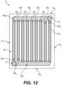
- FIG. 12 is a top plan view of the water block according to another alternative embodiment, illustrating the water block translucently to expose the internal fluid conduit;
- FIG. 13 is a schematic representation of a heat transfer system including an immersion cooling tank and the water block;
- FIG. 14 is a front elevation view of the water block according to an alternative embodiment in which the water block defines a plurality of external conduits;
- FIG. 15 is a cross-sectional view of the water block of FIG. 14 taken along line 15 - 15 in
- FIG. 14
- FIG. 18 is a top plan view of the base portion of the water block according to an alternative embodiment
- FIG. 21 is a perspective view, taken from a top, front, right side, of the water block according to another alternative embodiment
- FIG. 27 is a perspective view, taken from a top, front, right side, of the water block according to another alternative embodiment.
- FIGS. 1 to 3 illustrate a water block 10 in accordance with an embodiment of the present technology.
- the water block 10 is configured for cooling a heat-generating component 50 .
- the heat-generating component 50 is a central processing unit (CPU) of a computer system and is mounted to a motherboard thereof.
- the CPU 50 generates a significant amount of heat and, as is known, can benefit from cooling.
- the heat-generating component 50 could be any other suitable heat-generating electronic component (e.g., a graphics processing unit (GPU)) or an intermediary component disposed between the water block 10 and a heat-generating component.
- GPU graphics processing unit
- the body 100 comprises an external thermal transfer surface 110 on a first side of the water block 10 configured to be in contact with the heat-generating component 50 .
- the external thermal transfer surface 110 is said to be “in contact” with the heat-generating component 50 even in cases where a thermal paste is applied between the external thermal transfer surface 110 and the heat-generating component 50 , in a manner that is known in the art, to ensure adequate heat transfer between the heat-generating component 50 and the external thermal transfer surface 110 .
- the water block 10 is generally rectangular and has front and rear longitudinal ends 130 1 , 130 2 , and opposite lateral ends 131 1 , 131 2 .
- the water block 10 has a base portion 200 and a cover portion 300 affixed to the base portion 200 to form the body 100 of the water block 10 , including the ends 130 1 , 130 2 , 131 1 , 131 2 thereof.
- the base portion 200 is disposed between the cover portion 300 and the heat-generating component 50 .
- the base and cover portions 200 , 300 can be affixed to one another in various ways.
- the base portion 200 is welded to the cover portion 300 along a seam therebetween.
- the base and cover portions 200 , 300 are laser welded to one another.
- the water block 10 may be formed of a mono-block body that may be made via 3 D printing.
- the water block 10 may include additional parts affixed to one another to form the body 100 .
- the cover and base portions 200 , 300 are made of a thermally conductive material such as metal, for instance copper or aluminum.
- a thermally conductive material such as metal, for instance copper or aluminum.
- the base and cover portions 200 , 300 could be made from different thermally conductive materials in other embodiments, including combining different materials (e.g., cover portion 300 made from a different material than the base portion 200 ).
- the base portion 200 has an upper side 215 (internal side) and a lower side 217 (external side) opposite the upper side 215 .
- the external thermal transfer surface 110 is disposed on the lower side 217 of the base portion 200 .
- the upper surface 220 defines a continuous recess 280 extending from a first end 262 to a second end 264 .
- the recess 280 defines a lower fluid conduit portion 260 of the internal fluid conduit 15 such that the first and second ends 262 , 264 are the first and second ends of the lower fluid conduit portion 260 .
- the lower fluid conduit portion 260 is defined by the base portion 200 as the lower fluid conduit portion 260 is disposed between the external thermal transfer surface 110 and the upper external surface 120 .
- the recess 280 is machined into the upper surface 220 of the base portion 200 .
- the recess 280 can be milled into the upper surface 220 by a milling machine (e.g., a numerically controlled mill).
- the recess 280 may be provided in the base portion 200 in any other suitable way in other embodiments (e.g., molded or machined using electro erosion).
- the recess 280 has a height of approximately 4 mm and a width of approximately 2 mm. The dimensions of the recess 280 may be different in other embodiments.
- the first end 262 is located at the longitudinally-extending section 266 1 and the second end 264 is located at the longitudinally-extending section 266 9 such that the first end 262 and the second end 264 are located at the laterally furthest-most of the longitudinally-extending sections 266 1 - 266 9 respectively (i.e., the longitudinally-extending sections 266 1 - 266 9 which are most laterally spaced from one another).
- the first and second ends 262 , 264 of the lower fluid conduit portion 260 are located at diagonally opposite corners of the base portion 200 .
- the first end 262 is located proximate an intersection of a front longitudinal end 230 1 and a left lateral end 231 1 of the base portion 200
- the second end 264 is located proximate an intersection of an opposite rear longitudinal end 230 2 and an opposite right lateral end 231 2 of the base portion 200 .
- the first and second ends 262 , 264 are located proximate opposite longitudinal and lateral sides of the water block 10 .
- Other positions of the first and second ends 262 , 264 are contemplated in alternative embodiments.
- the first and second ends 262 , 264 of the lower fluid conduit portion 260 could be located proximate the same longitudinal end 230 1 , thereby defining an even number of longitudinally-extending sections of the serpentine path.
- first and second ends 262 , 264 of the lower fluid conduit portion 260 are still located at diagonally opposite corners of the base portion 200 , with the first end 262 disposed at the front manifold section 368 1 while the second end 264 is disposed at the rear manifold section 368 2 .
- the lower fluid conduit portion 260 has a generally sinusoidal pattern along at least part thereof.
- the longitudinally-extending sections 266 1 - 266 7 are not rectilinear but rather define a sinusoidal pattern along a majority of a length thereof.
- each longitudinally-extending section 266 i has a repetitive pattern approximating that of a sinusoidal function.
- each longitudinally-extending section 266 i has alternatingly-oriented undulations 267 deviating from a linear axis extending between opposite ends of the longitudinally-extending section 266 i .
- the sinusoidal pattern of the lower fluid conduit portion 260 provides a greater surface area for heat exchange between the fluid flowing in the lower fluid conduit portion 260 and the water block 10 .
- the sinusoidal pattern of the lower fluid conduit portion 260 aims to provide flow disturbances to enhance heat exchange between the fluid flowing in the lower fluid conduit portion 260 and the water block 10 .
- the lower fluid conduit portion 260 describes a generally spiral path along at least part of a span thereof between the first and second ends 262 , 264 of the lower fluid conduit portion 260 .
- the spiral path of the lower fluid conduit portion 260 is generally centered about the first end 262 (the inlet end 262 ) and has a plurality of ring sections 251 1 - 251 4 which are concentric about the first end 262 .
- the innermost ring sections 251 1 is closest to the first end 262 (and thus the inlet 20 ) and the outermost ring section 251 4 is furthest from the first end 262 .
- the second end 264 is located at the outermost ring section 251 4 .
- each ring section 251 i has a generally rectangular shape. In other examples, the ring sections may be circular in shape.
- the cover portion 300 has a lower side 310 and an upper side 320 opposite the lower side 310 .
- the upper external surface 120 is disposed on the upper side 320 .
- the cover portion 300 defines openings 302 , 303 which traverse the cover portion 300 form the lower side 310 to the upper side 320 , such that, when the cover portion 300 is placed atop the base portion 200 , the openings 302 , 303 are generally aligned with the first and second ends 262 , 264 of the lower fluid conduit portion 260 .
- the openings 302 , 303 thus define the fluid inlet 20 and the fluid outlet 30 of the water block 10 respectively.
- the cover portion 300 comprises the hollow fins 500 on its upper side 320 .
- the hollow fins 500 extend from the upper external surface 120 of the cover portion 300 in a height direction thereof.
- the hollow fins 500 are generally parallel to one another and are spaced apart laterally.
- each of the hollow fins 500 extends longitudinally from a front longitudinal end 502 to a rear longitudinal end 504 , a length of the hollow fin 500 being measured between the front and rear longitudinal ends 502 , 504 .
- the hollow fins 500 are rectilinear.
- the hollow fins 500 are hollow in that each hollow fin 500 defines a respective internal fin recess 510 which, as will be described below, forms part of the internal fluid conduit 15 of the water block 10 .
- each hollow fin 500 is shaped such that, a cross-sectional profile thereof taken along a plane normal to the length of the fin 500 (measured between the front and rear longitudinal ends 502 , 504 ) is generally rectangular. More specifically, the cross-sectional profile of the outer surfaces of the hollow fin 500 taken along said plane is generally rectangular.
- each hollow fin 500 has an upper end 506 defining an upper external surface 507 , and opposite lateral external surfaces 508 ( FIG. 2 ), all of which extend longitudinally between the front and rear longitudinal ends 502 , 504 .
- the lateral external surfaces 508 are generally parallel to one another, and the upper external surface 507 extends between the lateral external surfaces 508 .
- the cross-sectional shape of the fins 500 may be different in other embodiments.
- the hollow fins 500 define a plurality of external fin passages 515 therebetween.
- each fin passage 515 is defined between two consecutive hollow fins 500 , namely between opposite lateral external surfaces 508 thereof.
- an external fluid e.g., air or a dielectric fluid
- cover portion 300 is machined to form the external fin passages 515 between consecutive hollow fins 500 , thereby forming the hollow fins 500 as well.
- the hollow fins 500 and the fin passages 515 can be milled by a milling machine (e.g., a numerically controlled mill). Other manufacturing methods are also contemplated (e.g., molding).
- the cover portion 300 comprises a lower surface 312 defining the internal fin recesses 510 of the hollow fins 500 .
- each internal fin recess 510 extends longitudinally from a front recess end 351 to a rear recess end 353 .
- the length of each hollow fin 500 corresponds to at least a majority of the length of the body 100 .
- each internal fin recess 510 extends from the lower surface 312 to an internal upper fin surface 512 , thereby establishing a height of the fin recess 510 .
- the height of the internal fin recesses 510 is constant along the longitudinal direction (i.e., from the front recess end 351 to the rear recess end 353 ).
- Each internal fin recess 510 is bound on its lateral sides by two inner lateral fin surfaces 513 extending generally parallel to the lateral outer surfaces 508 of the corresponding hollow fin 500 .
- the internal fin recesses 510 have a generally rectangular cross-sectional profile.
- the internal fin recesses 510 are machined into the lower surface 312 of the cover portion 300 .
- the internal fin recesses 510 can be milled into the lower surface 312 by a milling machine (e.g., a numerically controlled mill).
- a milling machine e.g., a numerically controlled mill
- Other manufacturing methods are also contemplated (e.g., molding).
- each fin recess 510 has front and rear curved longitudinal end portions 355 (extending from the front and rear recess ends 351 , 355 ) along which the height of the fin recess 510 increases to a constant middle height MH of a central recess portion disposed centrally between the front and rear curved longitudinal end portions 355 .
- the internal upper fin surface 512 does not have square corners.
- This configuration may promote better flow of fluid within the internal fin recesses 510 and thereby improve thermal heat exchange at the hollow fins 500 , namely as the gradual increase in height to the middle height MH may help prevent separated flow within the hollow fins 500 and fluid recirculation zones. Moreover, avoiding having square corner sections of the internal fin recess 510 within which fluid does not easily flow may also prevent air pockets forming therein.
- the number of hollow fins 500 corresponds to the number of longitudinally-extending sections 266 1 - 266 9 .
- each internal fin recess 510 is aligned with a respective one of the longitudinally-extending sections 266 1 of the lower fluid conduit portion 260 of the base portion 200 . That is, as shown in FIG.
- each of the internal fin recesses 510 overlaps a majority of the corresponding longitudinally-extending section 266 1 - 266 9 such that the internal fin recesses 510 are a continuation, in the height direction of the water block 10 , of the longitudinally-extending sections 266 1 - 266 9 .
- the internal fin recesses 510 collaborate with the lower fluid conduit portion 260 to form the internal fluid conduit 15 of the water block 10 .
- the hollow fins 500 may also be shaped differently in other embodiments.
- the hollow fins 500 can provide the water block 10 with increased cooling efficiency and/or redundancy.
- a fluid e.g., air flowing within an enclosure of the heat-generating component 50
- the hollow fins 500 can also ensure a certain amount of redundancy of the water block 10 .
- the water block 10 may be configured differently in other embodiments. For instance, as will be described below, a single hollow fin may be provided having sections extending in different directions.
Landscapes
- Engineering & Computer Science (AREA)
- Microelectronics & Electronic Packaging (AREA)
- Physics & Mathematics (AREA)
- Thermal Sciences (AREA)
- General Engineering & Computer Science (AREA)
- Theoretical Computer Science (AREA)
- Mechanical Engineering (AREA)
- Human Computer Interaction (AREA)
- General Physics & Mathematics (AREA)
- Computer Hardware Design (AREA)
- Power Engineering (AREA)
- Heat-Exchange Devices With Radiators And Conduit Assemblies (AREA)
- Cooling Or The Like Of Semiconductors Or Solid State Devices (AREA)
- Road Signs Or Road Markings (AREA)
Abstract
Description
Claims (14)
Applications Claiming Priority (6)
| Application Number | Priority Date | Filing Date | Title |
|---|---|---|---|
| EP21305237 | 2021-02-26 | ||
| EP21305237 | 2021-02-26 | ||
| EP21305237.6 | 2021-02-26 | ||
| EP21305717.7 | 2021-05-28 | ||
| EP21305717.7A EP4050295A1 (en) | 2021-02-26 | 2021-05-28 | Water block having hollow fins |
| EP21305717 | 2021-05-28 |
Publications (2)
| Publication Number | Publication Date |
|---|---|
| US20220279679A1 US20220279679A1 (en) | 2022-09-01 |
| US12029010B2 true US12029010B2 (en) | 2024-07-02 |
Family
ID=75173208
Family Applications (1)
| Application Number | Title | Priority Date | Filing Date |
|---|---|---|---|
| US17/677,176 Active 2042-06-25 US12029010B2 (en) | 2021-02-26 | 2022-02-22 | Water block having hollow fins |
Country Status (5)
| Country | Link |
|---|---|
| US (1) | US12029010B2 (en) |
| EP (1) | EP4050295A1 (en) |
| KR (1) | KR20220122558A (en) |
| CN (1) | CN114967859A (en) |
| CA (1) | CA3149804A1 (en) |
Families Citing this family (3)
| Publication number | Priority date | Publication date | Assignee | Title |
|---|---|---|---|---|
| CN117029134A (en) * | 2023-08-24 | 2023-11-10 | 吉林大学 | A building phase change material cooling system coupled with water cooling and enhanced nighttime radiation heat dissipation |
| CN117161685A (en) * | 2023-08-30 | 2023-12-05 | 无锡江南计算技术研究所 | Processing method of runner and liquid cooling plate |
| TWI895804B (en) * | 2023-09-25 | 2025-09-01 | 鴻勁精密股份有限公司 | Temperature controlling unit, testing device, and processing machine |
Citations (47)
| Publication number | Priority date | Publication date | Assignee | Title |
|---|---|---|---|---|
| US5002123A (en) * | 1989-04-20 | 1991-03-26 | Microelectronics And Computer Technology Corporation | Low pressure high heat transfer fluid heat exchanger |
| US5316077A (en) * | 1992-12-09 | 1994-05-31 | Eaton Corporation | Heat sink for electrical circuit components |
| US20020056908A1 (en) | 1999-11-12 | 2002-05-16 | Michael Philip Brownell | Heatpipesink having integrated heat pipe and heat sink |
| US20030150599A1 (en) * | 2002-02-08 | 2003-08-14 | Kazutaka Suzuki | Cooling apparatus boiling and condensing refrigerant with effective performance in a titled position |
| US20040190253A1 (en) | 2003-03-31 | 2004-09-30 | Ravi Prasher | Channeled heat sink and chassis with integrated heat rejector for two-phase cooling |
| US20040190251A1 (en) | 2003-03-31 | 2004-09-30 | Ravi Prasher | Two-phase cooling utilizing microchannel heat exchangers and channeled heat sink |
| US20050039884A1 (en) * | 2003-08-20 | 2005-02-24 | Ivan Pawlenko | Conformal heat sink |
| CN2720630Y (en) | 2003-11-25 | 2005-08-24 | 陈德荣 | Radiating and heat-collecting device for fin-heat-tube in pipe |
| US20060162899A1 (en) * | 2005-01-26 | 2006-07-27 | Huang Wei C | Structure of liquid cooled waterblock with thermal conductivities |
| US20060237167A1 (en) * | 2004-03-15 | 2006-10-26 | Delta Electronics, Inc. | Heat sink |
| US20070025085A1 (en) | 2005-07-29 | 2007-02-01 | Hon Hai Precision Industry Co., Ltd. | Heat sink |
| US20070227703A1 (en) | 2006-03-31 | 2007-10-04 | Bhatti Mohinder S | Evaporatively cooled thermosiphon |
| US20070258213A1 (en) | 2006-05-03 | 2007-11-08 | International Business Machines Corporation | Apparatuses for dissipating heat from semiconductor devices |
| US20070258216A1 (en) * | 2004-09-13 | 2007-11-08 | Mcbain Richard A | Structures for holding cards incorporating electronic and/or micromachined components |
| US20080024990A1 (en) * | 2006-07-31 | 2008-01-31 | Yu-Huang Peng | Water block heat-dissipating structure |
| US20080029244A1 (en) * | 2006-08-02 | 2008-02-07 | Gilliland Don A | Heat sinks for dissipating a thermal load |
| US7388746B2 (en) | 2005-09-29 | 2008-06-17 | Samsung Electronics Co., Ltd. | Heatsink assembly |
| US20110079376A1 (en) | 2009-10-03 | 2011-04-07 | Wolverine Tube, Inc. | Cold plate with pins |
| US20120160466A1 (en) * | 2010-12-27 | 2012-06-28 | Hamilton Sundstrand Corporation | Surface cooler having channeled fins |
| DE202013001316U1 (en) | 2013-02-05 | 2013-05-10 | Asia Vital Components Co., Ltd. | Vapor Chamber cooler |
| US20140119393A1 (en) * | 2012-10-29 | 2014-05-01 | Coherent, Inc. | Macro-channel water-cooled heat-sink for diode-laser bars |
| US8737071B2 (en) | 2010-11-11 | 2014-05-27 | Huawei Technologies Co., Ltd. | Heat dissipation device |
| US20140262186A1 (en) * | 2013-03-14 | 2014-09-18 | Rochester Institute Of Technology | Heat Transfer System and Method Incorporating Tapered Flow Field |
| US8944147B2 (en) | 2010-05-28 | 2015-02-03 | Toyota Jidosha Kabushiki Kaisha | Heat exchanger and method for manufacturing same |
| US20150153116A1 (en) * | 2012-07-27 | 2015-06-04 | Kyocera Corporation | Flow path member, and heat exchanger and semiconductor manufacturing device using same |
| EP3089210A1 (en) | 2015-04-30 | 2016-11-02 | Cooler Master Co., Ltd. | Cooling module, water-cooled cooling module and cooling system |
| US9502329B2 (en) | 2011-05-16 | 2016-11-22 | Fuji Electric Co., Ltd. | Semiconductor module cooler |
| CN106469696A (en) | 2015-08-19 | 2017-03-01 | Acp动力公司 | The encapsulation of power semiconductor and chiller |
| US20170115071A1 (en) | 2015-10-26 | 2017-04-27 | Taiwan Microloops Corp. | Heat dissipation structure and water block having the same |
| US20170287809A1 (en) | 2016-04-01 | 2017-10-05 | International Business Machines Corporation | Compliant pin fin heat sink with base integral pins |
| US9845999B2 (en) | 2011-11-11 | 2017-12-19 | Showa Denko K.K. | Liquid-cooled-type cooling device and manufacturing method for same |
| US20180308780A1 (en) * | 2015-07-03 | 2018-10-25 | Zhejiang Jiaxi Optoelectronic Equipment Manufactur Ing Co., Ltd. | Thermally superconducting heat dissipation device and manufacturing method thereof |
| US20190033930A1 (en) | 2017-07-26 | 2019-01-31 | Optimus Water Cooling Corporation | Cooling device for use in heat dissipation associated with electronic components |
| US20190041105A1 (en) | 2017-08-07 | 2019-02-07 | Asia Vital Components Co., Ltd. | Heat-exchange structure for water cooling device |
| US10327355B2 (en) | 2015-01-29 | 2019-06-18 | Cooler Master Co., Ltd. | Water-cooling heat dissipation device and water block thereof |
| US10410954B2 (en) | 2015-05-05 | 2019-09-10 | Cooler Master Co., Ltd. | Cooling module, water-cooled cooling module and cooling system |
| US20190307020A1 (en) | 2018-03-30 | 2019-10-03 | Nidec Corporation | Cooling apparatus |
| US20190383559A1 (en) * | 2018-06-18 | 2019-12-19 | Fujitsu Limited | Heat exchanger for liquid immersion cooling |
| US10553522B1 (en) | 2018-08-13 | 2020-02-04 | International Business Machines Corporation | Semiconductor microcooler |
| US20200149830A1 (en) | 2018-11-14 | 2020-05-14 | Cooler Master Co.,Ltd. | Heat dissipation device and fin structure |
| US10743438B2 (en) * | 2016-07-25 | 2020-08-11 | Fujitsu Limited | Liquid cooling device, liquid cooling system, and control method of liquid cooling device |
| US10747276B2 (en) | 2018-06-06 | 2020-08-18 | Cooler Master Technology Inc. | Cooling system and water cooling radiator |
| US10809776B2 (en) | 2018-10-03 | 2020-10-20 | Asia Vital Components (China) Co., Ltd. | Water block mounting holder with reinforced structure |
| US20200373223A1 (en) | 2019-05-23 | 2020-11-26 | Ovh | Water block assembly |
| US11094611B2 (en) | 2019-10-08 | 2021-08-17 | Champ Tech Optical (Foshan) Corporation | Liquid cooled heat dissipation device |
| US20220029873A1 (en) * | 2020-07-22 | 2022-01-27 | Faurecia Clarion Electronics Europe | Method for estimation of an interfering signal, method for attenuation of an interfering signal contained in a received signal, and receiving system |
| US20220205723A1 (en) * | 2020-12-25 | 2022-06-30 | Cooler Master Co., Ltd. | Heat dissipation device |
-
2021
- 2021-05-28 EP EP21305717.7A patent/EP4050295A1/en active Pending
-
2022
- 2022-02-22 CA CA3149804A patent/CA3149804A1/en active Pending
- 2022-02-22 US US17/677,176 patent/US12029010B2/en active Active
- 2022-02-28 CN CN202210187433.7A patent/CN114967859A/en active Pending
- 2022-02-28 KR KR1020220025671A patent/KR20220122558A/en active Pending
Patent Citations (48)
| Publication number | Priority date | Publication date | Assignee | Title |
|---|---|---|---|---|
| US5002123A (en) * | 1989-04-20 | 1991-03-26 | Microelectronics And Computer Technology Corporation | Low pressure high heat transfer fluid heat exchanger |
| US5316077A (en) * | 1992-12-09 | 1994-05-31 | Eaton Corporation | Heat sink for electrical circuit components |
| US20020056908A1 (en) | 1999-11-12 | 2002-05-16 | Michael Philip Brownell | Heatpipesink having integrated heat pipe and heat sink |
| US20030150599A1 (en) * | 2002-02-08 | 2003-08-14 | Kazutaka Suzuki | Cooling apparatus boiling and condensing refrigerant with effective performance in a titled position |
| US20040190253A1 (en) | 2003-03-31 | 2004-09-30 | Ravi Prasher | Channeled heat sink and chassis with integrated heat rejector for two-phase cooling |
| US20040190251A1 (en) | 2003-03-31 | 2004-09-30 | Ravi Prasher | Two-phase cooling utilizing microchannel heat exchangers and channeled heat sink |
| US20050117300A1 (en) * | 2003-03-31 | 2005-06-02 | Ravi Prasher | Channeled heat sink and chassis with integrated heat rejecter for two-phase cooling |
| US20050039884A1 (en) * | 2003-08-20 | 2005-02-24 | Ivan Pawlenko | Conformal heat sink |
| CN2720630Y (en) | 2003-11-25 | 2005-08-24 | 陈德荣 | Radiating and heat-collecting device for fin-heat-tube in pipe |
| US20060237167A1 (en) * | 2004-03-15 | 2006-10-26 | Delta Electronics, Inc. | Heat sink |
| US20070258216A1 (en) * | 2004-09-13 | 2007-11-08 | Mcbain Richard A | Structures for holding cards incorporating electronic and/or micromachined components |
| US20060162899A1 (en) * | 2005-01-26 | 2006-07-27 | Huang Wei C | Structure of liquid cooled waterblock with thermal conductivities |
| US20070025085A1 (en) | 2005-07-29 | 2007-02-01 | Hon Hai Precision Industry Co., Ltd. | Heat sink |
| US7388746B2 (en) | 2005-09-29 | 2008-06-17 | Samsung Electronics Co., Ltd. | Heatsink assembly |
| US20070227703A1 (en) | 2006-03-31 | 2007-10-04 | Bhatti Mohinder S | Evaporatively cooled thermosiphon |
| US20070258213A1 (en) | 2006-05-03 | 2007-11-08 | International Business Machines Corporation | Apparatuses for dissipating heat from semiconductor devices |
| US20080024990A1 (en) * | 2006-07-31 | 2008-01-31 | Yu-Huang Peng | Water block heat-dissipating structure |
| US20080029244A1 (en) * | 2006-08-02 | 2008-02-07 | Gilliland Don A | Heat sinks for dissipating a thermal load |
| US20110079376A1 (en) | 2009-10-03 | 2011-04-07 | Wolverine Tube, Inc. | Cold plate with pins |
| US8944147B2 (en) | 2010-05-28 | 2015-02-03 | Toyota Jidosha Kabushiki Kaisha | Heat exchanger and method for manufacturing same |
| US8737071B2 (en) | 2010-11-11 | 2014-05-27 | Huawei Technologies Co., Ltd. | Heat dissipation device |
| US20120160466A1 (en) * | 2010-12-27 | 2012-06-28 | Hamilton Sundstrand Corporation | Surface cooler having channeled fins |
| US9502329B2 (en) | 2011-05-16 | 2016-11-22 | Fuji Electric Co., Ltd. | Semiconductor module cooler |
| US9845999B2 (en) | 2011-11-11 | 2017-12-19 | Showa Denko K.K. | Liquid-cooled-type cooling device and manufacturing method for same |
| US20150153116A1 (en) * | 2012-07-27 | 2015-06-04 | Kyocera Corporation | Flow path member, and heat exchanger and semiconductor manufacturing device using same |
| US20140119393A1 (en) * | 2012-10-29 | 2014-05-01 | Coherent, Inc. | Macro-channel water-cooled heat-sink for diode-laser bars |
| DE202013001316U1 (en) | 2013-02-05 | 2013-05-10 | Asia Vital Components Co., Ltd. | Vapor Chamber cooler |
| US20140262186A1 (en) * | 2013-03-14 | 2014-09-18 | Rochester Institute Of Technology | Heat Transfer System and Method Incorporating Tapered Flow Field |
| US10327355B2 (en) | 2015-01-29 | 2019-06-18 | Cooler Master Co., Ltd. | Water-cooling heat dissipation device and water block thereof |
| EP3089210A1 (en) | 2015-04-30 | 2016-11-02 | Cooler Master Co., Ltd. | Cooling module, water-cooled cooling module and cooling system |
| US10410954B2 (en) | 2015-05-05 | 2019-09-10 | Cooler Master Co., Ltd. | Cooling module, water-cooled cooling module and cooling system |
| US20180308780A1 (en) * | 2015-07-03 | 2018-10-25 | Zhejiang Jiaxi Optoelectronic Equipment Manufactur Ing Co., Ltd. | Thermally superconducting heat dissipation device and manufacturing method thereof |
| CN106469696A (en) | 2015-08-19 | 2017-03-01 | Acp动力公司 | The encapsulation of power semiconductor and chiller |
| US20170115071A1 (en) | 2015-10-26 | 2017-04-27 | Taiwan Microloops Corp. | Heat dissipation structure and water block having the same |
| US20170287809A1 (en) | 2016-04-01 | 2017-10-05 | International Business Machines Corporation | Compliant pin fin heat sink with base integral pins |
| US10743438B2 (en) * | 2016-07-25 | 2020-08-11 | Fujitsu Limited | Liquid cooling device, liquid cooling system, and control method of liquid cooling device |
| US20190033930A1 (en) | 2017-07-26 | 2019-01-31 | Optimus Water Cooling Corporation | Cooling device for use in heat dissipation associated with electronic components |
| US20190041105A1 (en) | 2017-08-07 | 2019-02-07 | Asia Vital Components Co., Ltd. | Heat-exchange structure for water cooling device |
| US20190307020A1 (en) | 2018-03-30 | 2019-10-03 | Nidec Corporation | Cooling apparatus |
| US10747276B2 (en) | 2018-06-06 | 2020-08-18 | Cooler Master Technology Inc. | Cooling system and water cooling radiator |
| US20190383559A1 (en) * | 2018-06-18 | 2019-12-19 | Fujitsu Limited | Heat exchanger for liquid immersion cooling |
| US10553522B1 (en) | 2018-08-13 | 2020-02-04 | International Business Machines Corporation | Semiconductor microcooler |
| US10809776B2 (en) | 2018-10-03 | 2020-10-20 | Asia Vital Components (China) Co., Ltd. | Water block mounting holder with reinforced structure |
| US20200149830A1 (en) | 2018-11-14 | 2020-05-14 | Cooler Master Co.,Ltd. | Heat dissipation device and fin structure |
| US20200373223A1 (en) | 2019-05-23 | 2020-11-26 | Ovh | Water block assembly |
| US11094611B2 (en) | 2019-10-08 | 2021-08-17 | Champ Tech Optical (Foshan) Corporation | Liquid cooled heat dissipation device |
| US20220029873A1 (en) * | 2020-07-22 | 2022-01-27 | Faurecia Clarion Electronics Europe | Method for estimation of an interfering signal, method for attenuation of an interfering signal contained in a received signal, and receiving system |
| US20220205723A1 (en) * | 2020-12-25 | 2022-06-30 | Cooler Master Co., Ltd. | Heat dissipation device |
Non-Patent Citations (5)
| Title |
|---|
| Chilldyne Liquid Cooling System Overview, 2019, http://www.chilldyne.com/wp-content/uploads/2019/12/Chilldyne-Liquid-Cooling-System-2019.pdf accessed Feb. 17, 2022, pdf 2 pages. |
| English Abstract for CN106469696 retrieved on Espacenet on Feb. 16, 2022. |
| English Abstract for CN2720630 retrieved on Espacenet on Feb. 16, 2022. |
| English Abstract for DE202013001316 retrieved on Espacenet on Feb. 16, 2022. |
| Extended European Search Report with regard to the EP Patent Application No. 21305717_7 completed Nov. 10, 2021. |
Also Published As
| Publication number | Publication date |
|---|---|
| CN114967859A (en) | 2022-08-30 |
| CA3149804A1 (en) | 2022-08-26 |
| US20220279679A1 (en) | 2022-09-01 |
| KR20220122558A (en) | 2022-09-02 |
| EP4050295A1 (en) | 2022-08-31 |
Similar Documents
| Publication | Publication Date | Title |
|---|---|---|
| KR102600257B1 (en) | Water block assembly | |
| US12029010B2 (en) | Water block having hollow fins | |
| US20220316816A1 (en) | Heat sink having non-straight fins for orienting a flow of an immersive cooling fluid | |
| CN110874127B (en) | Heat transfer device with fluid conduit | |
| CN101796635B (en) | Method and device for cooling a heat generating component | |
| CN107452699B (en) | IGBT module liquid cooling plate based on parallel connection of liquid flow grooves and manufacturing method thereof | |
| JP2023501829A (en) | Cold plates and systems for cooling electronic devices | |
| JP2020532875A (en) | Heat sink for immersion cooling, heat sink device and module | |
| US20060226539A1 (en) | Integrated circuit coolant microchannel assembly with targeted channel configuration | |
| US11876036B2 (en) | Fluid cooling system including embedded channels and cold plates | |
| CN102834688A (en) | Phase change cooler and electronic equipment provided with same | |
| CN118426555A (en) | Liquid cooling server combining cold plate type and immersion type and heat dissipation design method | |
| JP5114967B2 (en) | Cooling device and semiconductor power conversion device | |
| JP2025512897A (en) | Cooling device with heat sink for at least one microchip - Patent application | |
| EP4156251B1 (en) | Cooling block for cooling a heat-generating electronic component and method for manufacturing thereof | |
| JP4517962B2 (en) | Cooling device for electronic equipment | |
| CN222928717U (en) | Liquid cooling plate for radiating electronic device | |
| CN118714807A (en) | A pin-fin dual-channel heat dissipation device with a symmetrical double-layer flow channel design | |
| CN120676601A (en) | Liquid cooling plate | |
| CN119403084A (en) | Double-layer heat dissipation device for electronic devices |
Legal Events
| Date | Code | Title | Description |
|---|---|---|---|
| AS | Assignment |
Owner name: OVH, FRANCE Free format text: ASSIGNMENT OF ASSIGNORS INTEREST;ASSIGNORS:CHEHADE, ALI;CHAKIR, ANAS;BAUDUIN, HADRIEN;SIGNING DATES FROM 20210608 TO 20210614;REEL/FRAME:059067/0706 |
|
| STPP | Information on status: patent application and granting procedure in general |
Free format text: DOCKETED NEW CASE - READY FOR EXAMINATION |
|
| STPP | Information on status: patent application and granting procedure in general |
Free format text: NON FINAL ACTION MAILED |
|
| STPP | Information on status: patent application and granting procedure in general |
Free format text: RESPONSE TO NON-FINAL OFFICE ACTION ENTERED AND FORWARDED TO EXAMINER |
|
| STPP | Information on status: patent application and granting procedure in general |
Free format text: FINAL REJECTION MAILED |
|
| STPP | Information on status: patent application and granting procedure in general |
Free format text: ADVISORY ACTION MAILED |
|
| STPP | Information on status: patent application and granting procedure in general |
Free format text: DOCKETED NEW CASE - READY FOR EXAMINATION |
|
| STPP | Information on status: patent application and granting procedure in general |
Free format text: NOTICE OF ALLOWANCE MAILED -- APPLICATION RECEIVED IN OFFICE OF PUBLICATIONS |
|
| STPP | Information on status: patent application and granting procedure in general |
Free format text: PUBLICATIONS -- ISSUE FEE PAYMENT VERIFIED |
|
| STCF | Information on status: patent grant |
Free format text: PATENTED CASE |
|
| CC | Certificate of correction |