US12011348B2 - Coiled anchor for supporting prosthetic heart valve, prosthetic heart valve, and deployment device - Google Patents
Coiled anchor for supporting prosthetic heart valve, prosthetic heart valve, and deployment device Download PDFInfo
- Publication number
- US12011348B2 US12011348B2 US18/063,934 US202218063934A US12011348B2 US 12011348 B2 US12011348 B2 US 12011348B2 US 202218063934 A US202218063934 A US 202218063934A US 12011348 B2 US12011348 B2 US 12011348B2
- Authority
- US
- United States
- Prior art keywords
- anchor
- valve
- coil
- helical
- turns
- Prior art date
- Legal status (The legal status is an assumption and is not a legal conclusion. Google has not performed a legal analysis and makes no representation as to the accuracy of the status listed.)
- Active, expires
Links
Images


Classifications
-
- A—HUMAN NECESSITIES
- A61—MEDICAL OR VETERINARY SCIENCE; HYGIENE
- A61F—FILTERS IMPLANTABLE INTO BLOOD VESSELS; PROSTHESES; DEVICES PROVIDING PATENCY TO, OR PREVENTING COLLAPSING OF, TUBULAR STRUCTURES OF THE BODY, e.g. STENTS; ORTHOPAEDIC, NURSING OR CONTRACEPTIVE DEVICES; FOMENTATION; TREATMENT OR PROTECTION OF EYES OR EARS; BANDAGES, DRESSINGS OR ABSORBENT PADS; FIRST-AID KITS
- A61F2/00—Filters implantable into blood vessels; Prostheses, i.e. artificial substitutes or replacements for parts of the body; Appliances for connecting them with the body; Devices providing patency to, or preventing collapsing of, tubular structures of the body, e.g. stents
- A61F2/02—Prostheses implantable into the body
- A61F2/24—Heart valves ; Vascular valves, e.g. venous valves; Heart implants, e.g. passive devices for improving the function of the native valve or the heart muscle; Transmyocardial revascularisation [TMR] devices; Valves implantable in the body
- A61F2/2412—Heart valves ; Vascular valves, e.g. venous valves; Heart implants, e.g. passive devices for improving the function of the native valve or the heart muscle; Transmyocardial revascularisation [TMR] devices; Valves implantable in the body with soft flexible valve members, e.g. tissue valves shaped like natural valves
- A61F2/2418—Scaffolds therefor, e.g. support stents
-
- A—HUMAN NECESSITIES
- A61—MEDICAL OR VETERINARY SCIENCE; HYGIENE
- A61F—FILTERS IMPLANTABLE INTO BLOOD VESSELS; PROSTHESES; DEVICES PROVIDING PATENCY TO, OR PREVENTING COLLAPSING OF, TUBULAR STRUCTURES OF THE BODY, e.g. STENTS; ORTHOPAEDIC, NURSING OR CONTRACEPTIVE DEVICES; FOMENTATION; TREATMENT OR PROTECTION OF EYES OR EARS; BANDAGES, DRESSINGS OR ABSORBENT PADS; FIRST-AID KITS
- A61F2/00—Filters implantable into blood vessels; Prostheses, i.e. artificial substitutes or replacements for parts of the body; Appliances for connecting them with the body; Devices providing patency to, or preventing collapsing of, tubular structures of the body, e.g. stents
- A61F2/02—Prostheses implantable into the body
- A61F2/24—Heart valves ; Vascular valves, e.g. venous valves; Heart implants, e.g. passive devices for improving the function of the native valve or the heart muscle; Transmyocardial revascularisation [TMR] devices; Valves implantable in the body
- A61F2/2427—Devices for manipulating or deploying heart valves during implantation
- A61F2/243—Deployment by mechanical expansion
-
- A—HUMAN NECESSITIES
- A61—MEDICAL OR VETERINARY SCIENCE; HYGIENE
- A61F—FILTERS IMPLANTABLE INTO BLOOD VESSELS; PROSTHESES; DEVICES PROVIDING PATENCY TO, OR PREVENTING COLLAPSING OF, TUBULAR STRUCTURES OF THE BODY, e.g. STENTS; ORTHOPAEDIC, NURSING OR CONTRACEPTIVE DEVICES; FOMENTATION; TREATMENT OR PROTECTION OF EYES OR EARS; BANDAGES, DRESSINGS OR ABSORBENT PADS; FIRST-AID KITS
- A61F2/00—Filters implantable into blood vessels; Prostheses, i.e. artificial substitutes or replacements for parts of the body; Appliances for connecting them with the body; Devices providing patency to, or preventing collapsing of, tubular structures of the body, e.g. stents
- A61F2/02—Prostheses implantable into the body
- A61F2/24—Heart valves ; Vascular valves, e.g. venous valves; Heart implants, e.g. passive devices for improving the function of the native valve or the heart muscle; Transmyocardial revascularisation [TMR] devices; Valves implantable in the body
- A61F2/2427—Devices for manipulating or deploying heart valves during implantation
- A61F2/2436—Deployment by retracting a sheath
-
- A—HUMAN NECESSITIES
- A61—MEDICAL OR VETERINARY SCIENCE; HYGIENE
- A61F—FILTERS IMPLANTABLE INTO BLOOD VESSELS; PROSTHESES; DEVICES PROVIDING PATENCY TO, OR PREVENTING COLLAPSING OF, TUBULAR STRUCTURES OF THE BODY, e.g. STENTS; ORTHOPAEDIC, NURSING OR CONTRACEPTIVE DEVICES; FOMENTATION; TREATMENT OR PROTECTION OF EYES OR EARS; BANDAGES, DRESSINGS OR ABSORBENT PADS; FIRST-AID KITS
- A61F2/00—Filters implantable into blood vessels; Prostheses, i.e. artificial substitutes or replacements for parts of the body; Appliances for connecting them with the body; Devices providing patency to, or preventing collapsing of, tubular structures of the body, e.g. stents
- A61F2/02—Prostheses implantable into the body
- A61F2/24—Heart valves ; Vascular valves, e.g. venous valves; Heart implants, e.g. passive devices for improving the function of the native valve or the heart muscle; Transmyocardial revascularisation [TMR] devices; Valves implantable in the body
- A61F2/2409—Support rings therefor, e.g. for connecting valves to tissue
-
- A—HUMAN NECESSITIES
- A61—MEDICAL OR VETERINARY SCIENCE; HYGIENE
- A61F—FILTERS IMPLANTABLE INTO BLOOD VESSELS; PROSTHESES; DEVICES PROVIDING PATENCY TO, OR PREVENTING COLLAPSING OF, TUBULAR STRUCTURES OF THE BODY, e.g. STENTS; ORTHOPAEDIC, NURSING OR CONTRACEPTIVE DEVICES; FOMENTATION; TREATMENT OR PROTECTION OF EYES OR EARS; BANDAGES, DRESSINGS OR ABSORBENT PADS; FIRST-AID KITS
- A61F2210/00—Particular material properties of prostheses classified in groups A61F2/00 - A61F2/26 or A61F2/82 or A61F9/00 or A61F11/00 or subgroups thereof
- A61F2210/0014—Particular material properties of prostheses classified in groups A61F2/00 - A61F2/26 or A61F2/82 or A61F9/00 or A61F11/00 or subgroups thereof using shape memory or superelastic materials, e.g. nitinol
-
- A—HUMAN NECESSITIES
- A61—MEDICAL OR VETERINARY SCIENCE; HYGIENE
- A61F—FILTERS IMPLANTABLE INTO BLOOD VESSELS; PROSTHESES; DEVICES PROVIDING PATENCY TO, OR PREVENTING COLLAPSING OF, TUBULAR STRUCTURES OF THE BODY, e.g. STENTS; ORTHOPAEDIC, NURSING OR CONTRACEPTIVE DEVICES; FOMENTATION; TREATMENT OR PROTECTION OF EYES OR EARS; BANDAGES, DRESSINGS OR ABSORBENT PADS; FIRST-AID KITS
- A61F2210/00—Particular material properties of prostheses classified in groups A61F2/00 - A61F2/26 or A61F2/82 or A61F9/00 or A61F11/00 or subgroups thereof
- A61F2210/0076—Particular material properties of prostheses classified in groups A61F2/00 - A61F2/26 or A61F2/82 or A61F9/00 or A61F11/00 or subgroups thereof multilayered, e.g. laminated structures
-
- A—HUMAN NECESSITIES
- A61—MEDICAL OR VETERINARY SCIENCE; HYGIENE
- A61F—FILTERS IMPLANTABLE INTO BLOOD VESSELS; PROSTHESES; DEVICES PROVIDING PATENCY TO, OR PREVENTING COLLAPSING OF, TUBULAR STRUCTURES OF THE BODY, e.g. STENTS; ORTHOPAEDIC, NURSING OR CONTRACEPTIVE DEVICES; FOMENTATION; TREATMENT OR PROTECTION OF EYES OR EARS; BANDAGES, DRESSINGS OR ABSORBENT PADS; FIRST-AID KITS
- A61F2230/00—Geometry of prostheses classified in groups A61F2/00 - A61F2/26 or A61F2/82 or A61F9/00 or A61F11/00 or subgroups thereof
- A61F2230/0063—Three-dimensional shapes
- A61F2230/0069—Three-dimensional shapes cylindrical
-
- A—HUMAN NECESSITIES
- A61—MEDICAL OR VETERINARY SCIENCE; HYGIENE
- A61F—FILTERS IMPLANTABLE INTO BLOOD VESSELS; PROSTHESES; DEVICES PROVIDING PATENCY TO, OR PREVENTING COLLAPSING OF, TUBULAR STRUCTURES OF THE BODY, e.g. STENTS; ORTHOPAEDIC, NURSING OR CONTRACEPTIVE DEVICES; FOMENTATION; TREATMENT OR PROTECTION OF EYES OR EARS; BANDAGES, DRESSINGS OR ABSORBENT PADS; FIRST-AID KITS
- A61F2230/00—Geometry of prostheses classified in groups A61F2/00 - A61F2/26 or A61F2/82 or A61F9/00 or A61F11/00 or subgroups thereof
- A61F2230/0063—Three-dimensional shapes
- A61F2230/0091—Three-dimensional shapes helically-coiled or spirally-coiled, i.e. having a 2-D spiral cross-section
-
- A—HUMAN NECESSITIES
- A61—MEDICAL OR VETERINARY SCIENCE; HYGIENE
- A61F—FILTERS IMPLANTABLE INTO BLOOD VESSELS; PROSTHESES; DEVICES PROVIDING PATENCY TO, OR PREVENTING COLLAPSING OF, TUBULAR STRUCTURES OF THE BODY, e.g. STENTS; ORTHOPAEDIC, NURSING OR CONTRACEPTIVE DEVICES; FOMENTATION; TREATMENT OR PROTECTION OF EYES OR EARS; BANDAGES, DRESSINGS OR ABSORBENT PADS; FIRST-AID KITS
- A61F2250/00—Special features of prostheses classified in groups A61F2/00 - A61F2/26 or A61F2/82 or A61F9/00 or A61F11/00 or subgroups thereof
- A61F2250/0058—Additional features; Implant or prostheses properties not otherwise provided for
- A61F2250/006—Additional features; Implant or prostheses properties not otherwise provided for modular
- A61F2250/0063—Nested prosthetic parts
Definitions
- the invention generally relates to medical devices and procedures pertaining to prosthetic heart valves. More specifically, the invention relates to replacement of heart valves that may have malformations and/or dysfunctions. Embodiments of the invention relate to a prosthetic heart valve for replacing a mitral valve in the heart, an anchor to facilitate and maintain a positioning of the prosthetic heart valve in the native valve, and deployment devices and procedures associated with implantation of the prosthetic heart valve.
- the mitral valve controls the flow of blood between the left atrium and the left ventricle of the human heart. After the left atrium receives oxygenated blood from the lungs via the pulmonary veins, the mitral valve permits the flow of the oxygenated blood from the left atrium into the left ventricle. When the left ventricle contracts, the oxygenated blood held in the left ventricle is delivered through the aortic valve and the aorta to the rest of the body. Meanwhile, the mitral valve closes during ventricular contraction, to prevent the flow of blood back into the left atrium.
- chordae tendineae connect the mitral valve to the papillary muscles along opposing walls of the left ventricle.
- the chordae tendineae are schematically illustrated in both the heart cross-section of FIG. 1 and the top view of the mitral valve in FIG. 2 .
- the papillary muscles Just before and during ventricular contraction, the papillary muscles also contract and maintain tension in the chordae tendineae, to hold the leaflets of the mitral valve in the closed position and preventing them from turning inside-out and back into the atrium, thereby also preventing backflow of the oxygenated blood into the atrium.
- FIG. 2 A general shape of the mitral valve and its leaflets as seen from the left atrium is illustrated in FIG. 2 . Complications of the mitral valve can potentially cause fatal heart failure.
- mitral valve leak also known as mitral regurgitation, characterized by the abnormal leaking of blood from the left ventricle back into the left atrium through the mitral valve. In these circumstances, it may be desirable to repair the mitral valve or to replace the functionality of the mitral valve with that of a prosthetic heart valve.
- mitral valve repair has been more popular than valve replacement, where prior research and development has been limited.
- the field of transcatheter aortic valve replacement has developed and has gained widespread success. This discrepancy stems from replacement of a mitral valve being more difficult than aortic valve replacement in many respects, for example, due to the physical structure of the valve and more difficult access to the valve.
- the most prominent obstacle for mitral valve replacement is anchoring or retaining the valve in position, due to the valve being subject to a large cyclic load. Especially during ventricular contraction, the movement of the heart and the load on the valve may combine to shift or dislodge a prosthetic valve. Also, the movement and rhythmic load can fatigue materials, leading to fractures of the implanted valve. If the orientation of a mitral prosthesis is unintentionally shifted, blood flow between the left atrium and the left ventricle may be obstructed or otherwise negatively affected. While puncturing the tissue in or around the mitral valve annulus to better anchor an implanted valve is an option for retaining the placement of the implant, this may potentially lead to unintended perforation of the heart and patient injury.
- mitral valve replacement is the size and shape of the native mitral valve.
- Aortic valves are more circular in shape than mitral valves.
- the need for aortic valve replacement arises due to, for example, aortic valve stenosis, when the aortic valve narrows due to reasons such as calcification and/or hardening of the aortic valve leaflets.
- the aortic valve annulus itself generally forms a more stable anchoring site for a prosthetic valve than a mitral valve annulus, which is quite large and non-circular.
- a circular mitral valve implant that is too small may cause leaks around the implanted valve (i.e., paravalvular leak) if a good seal is not established around the valve.
- a circular valve implant that is too large may stretch out and damage the valve annulus.
- the outer shape of a valve implant can also potentially be manipulated to better fit the mitral valve annulus, for example, through fabric cuff additions on an outer surface of the implant. However, these additions may restrict valve delivery through a catheter and/or minimally invasive procedures, since the additional fabric may be difficult to compress and deploy through a catheter.
- valves Since many valves have been developed for the aortic position, it would be desirable to try to take advantage of these existing valve technologies and to utilize the same or similar valves in mitral valve replacements. It would therefore be useful to create a mitral anchor or docking station for such preexisting prosthetic valves.
- An existing valve developed for the aortic position perhaps with some modification, could then be implanted in such an anchor or docking station.
- Some previously developed valves may fit well with little or no modification, such as the Edwards Lifesciences SapienTM valve.
- Embodiments of the invention provide a stable docking station for retaining a mitral valve replacement prosthesis.
- Other devices and methods are provided to improve the positioning and deployment of such docking stations and/or the replacement prosthesis therein, for example, during various non-invasive or minimally invasive procedures.
- the devices and methods may also serve to prevent or greatly reduce regurgitation or leaking of blood around the replacement prosthesis, such as leakage through the commissures of the native mitral valve outside of the prosthesis.
- Features of the invention are directed to a docking or anchoring device that more effectively anchors a replacement valve prosthesis in the mitral valve annulus.
- Other features of the invention are directed to a replacement valve prosthesis that more effectively interacts with an anchoring device according to embodiments of the invention and with surrounding portions of the native mitral valve and other portions of the heart.
- Still other features of the invention are directed to docking or anchoring devices and methods for more effectively deploying different portions of the anchoring devices above and below the native mitral valve annulus (i.e., deploying separate portions of the anchoring devices into the left atrium and left ventricle, respectively).
- Still other features of the invention are directed to corralling or holding the chordae tendineae together during deployment of the docking or anchoring devices, to more easily position the docking or anchoring devices around the native valve leaflets and the chordae tendineae.
- a coiled anchor for docking a mitral valve prosthesis at a native mitral valve of a heart has a first end, a second end, and a central axis extending between the first and second ends, and defines an inner space coaxial with the central axis.
- the coiled anchor includes a coiled core including a bio-compatible metal or metal alloy and having a plurality of turns extending around the central axis in a first position, and a cover layer around the core, the cover layer including a bio-compatible material that is less rigid than the metal or metal alloy of the coiled core.
- the coiled anchor is adjustable from the first position to a second position wherein at least one of the plurality of turns is straightened for the coiled anchor to be delivered through a catheter to the native mitral valve, and from the second position back to the first position.
- the coiled anchor is implantable at the native mitral valve with at least a portion on one side of the native mitral valve in a left atrium of the heart and at least a portion on an opposite side of the native mitral valve in a left ventricle of the heart, to support or hold the mitral valve prosthesis in the inner space when the coiled anchor is implanted at the native mitral valve
- the coiled anchor can be included in a system for implanting at a mitral valve, where the system can further include a mitral valve prosthesis including an expandable frame and housing a plurality of leaflets for controlling blood flow therethrough, wherein the frame is expandable from a collapsed first position wherein the frame has a first outer diameter for delivery of the mitral valve prosthesis through a catheter to an expanded second position wherein the frame has a second outer diameter greater than the first outer diameter.
- a mitral valve prosthesis including an expandable frame and housing a plurality of leaflets for controlling blood flow therethrough, wherein the frame is expandable from a collapsed first position wherein the frame has a first outer diameter for delivery of the mitral valve prosthesis through a catheter to an expanded second position wherein the frame has a second outer diameter greater than the first outer diameter.
- a coiled anchor for docking a mitral valve prosthesis at a native mitral valve of a heart has a first end, a second end, and a central axis extending between the first and second ends, and defines an inner space coaxial with the central axis.
- the coiled anchor includes a first coil having a plurality of turns in a first circumferential direction and extending from a first end to a second end, a second coil having a plurality of turns in a second circumferential direction opposite to the first circumferential direction and extending from a first end to a second end, and a joint configured to hold the first end of the first coil and the first end of the second coil together, such that the first and second coils each extends away from the joint and from one another along the central axis.
- the coiled anchor has a first position where the respective turns of the first coil and the second coil each extends around the central axis.
- the coiled anchor is adjustable from the first position to a second position wherein at least one of the plurality of turns of the first coil or the second coil is straightened for the coiled anchor to be delivered through a catheter to the native mitral valve, and from the second position back to the first position.
- the coiled anchor is implantable at the native mitral valve with at least a portion of the first coil on one side of the native mitral valve in a left atrium of the heart, and at least a portion of the second coil on an opposite side of the native mitral valve in a left ventricle of the heart, to support or hold the mitral valve prosthesis in the inner space when the coiled anchor is implanted at the native mitral valve.
- a method for delivering a coiled anchor that is configured to dock a mitral valve prosthesis at a native mitral valve of a heart includes positioning a catheter for delivery of the coiled anchor at the native mitral valve, positioning a loop around chordae tendineae, closing the loop to draw the chordae tendineae together, advancing the coiled anchor out of the catheter and around the chordae tendineae, and removing the loop and the catheter.
- mitral valve replacement can be realized through a variety of different implantation approaches. Embodiments of the invention thus provide flexibility with different ways and options for implanting a replacement mitral valve.
- FIG. 1 shows a schematic cross-sectional view of a human heart
- FIG. 2 shows a schematic top view of the mitral valve annulus of a heart
- FIGS. 3 A to 3 E show various views of a coil anchor according to an embodiment of the invention
- FIGS. 4 A and 4 B are respective images of an uncovered coil and a covered coil according to an embodiment of the invention.
- FIGS. 5 A to 5 F show a process of deploying a helical coil anchor via a transapical procedure according to an embodiment of the invention
- FIGS. 6 A to 6 D show a process of deploying a helical coil anchor via a transseptal procedure according to another embodiment of the invention
- FIGS. 7 A and 7 B show side cross-sectional views of a helical coil anchor deployed in the mitral position, with and without an implanted valve prosthesis, respectively, according to an embodiment of the invention
- FIGS. 8 A and 8 B respectively show a perspective schematic view of an exemplary transcatheter valve prosthesis, and a cross-section of a portion of the valve prosthesis, according to an embodiment of the invention
- FIGS. 9 A and 9 B respectively show a valve prosthesis held in a helical coil according to an embodiment of the invention, and a flaring that occurs to a frame of the valve prosthesis according to an embodiment of the invention;
- FIGS. 10 A and 10 B are respective images illustrating the flaring effect of a valve prosthesis according to an embodiment of the invention.
- FIGS. 11 A and 11 B are schematic images showing a cuff or protective layer added to a valve prosthesis according to other embodiments of the invention.
- FIG. 12 shows a perspective view of a helical coil anchor according to another embodiment of the invention.
- FIGS. 13 A and 13 B respectively show the helical coil anchor of FIG. 12 being deployed at a mitral position, and the helical coil anchor of FIG. 12 in its final deployed position;
- FIG. 14 shows a modified deployment system according to another embodiment of the invention.
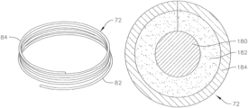
- FIG. 3 A shows a perspective view of a helical anchor 72
- FIG. 3 B shows a side view of the anchor 72
- FIG. 3 C shows a top view of the anchor 72
- the helical anchor 72 includes a coil with a plurality of turns extending along a central axis of the anchor.
- the anchor 72 has a series of lower turns or coils 82 and a series of upper turns or coils 84 .
- the individual turns of the lower coils 82 are spaced apart from one another by small gaps. Meanwhile, the individual turns of the upper coils 84 are wound more closely to one another.
- the turns of the lower coils 82 have a larger radius of curvature than the turns of the upper coils 84 , and therefore form a larger inner annular space.
- the anchor 72 twists or coils around a central axis of the anchor 72 to provide a generally circular or cylindrical space therein that can more easily hold and anchor a circular valve prosthesis than can the non-circular shape of the native mitral valve annulus seen in FIG. 2 . Therefore, as can be seen in FIG. 3 D , when a helical anchor 72 is positioned about a mitral valve 44 , the helical anchor 72 provides a more solid and structurally stable docking station or site for docking or coupling valve prostheses to the native mitral valve annulus. Passage of a portion of the anchor 72 at a commissure 80 of the mitral valve 44 (as seen in FIG.
- 3 D allows for placement of the anchor 72 both above and below the mitral valve annulus, for more secure anchoring of a valve prosthesis therein.
- a smallest inner space defined by the coils of the anchor 72 can be undersized relative to an expanded diameter of a valve prosthesis, such that a radial pressure is generated between the anchor 72 and the valve prosthesis when the prosthesis is expanded therein.
- a core 180 of the helical coil 72 is constructed of or includes a shape memory material, such as Nitinol.
- the core 180 of the helical coil 72 can be made of or include other bio-compatible materials, for example, other alloys, or for example, metals such as titanium or stainless steel.
- the coil can have enlarged and/or rounded ends, for example, to prevent tips at ends of the coil 72 from damaging surrounding tissue during deployment.
- FIGS. 3 A, 3 B, and 3 E the last of which illustrates a cross-section of a portion of the helical coil 72 , the core 180 of the coil 72 is covered or surrounded by a foam layer 182 and a cloth cover 184 .
- the foam layer 182 is a Biomerix foam layer, for example, a 2 millimeter thick layer of polyurethane sheet material
- the cloth cover 184 is made of or includes a polyester material.
- the respective ends of the foam layer 182 and cloth cover 184 meet circumferentially around the coil core 180 at substantially the same place.
- the foam layer 182 and cloth cover 184 are wrapped around the coil core 180 and attached at different circumferential points around the coil core 180 .
- the layers 182 , 184 can be attached together to the coil core 180 , or can be attached separately to the coil core 180 .
- the fabric or cloth cover 184 that covers the helical coil is, for example, a polyethylene terephthalate (PET) polyester material.
- PET polyethylene terephthalate
- the fabric can have a thickness of 0.008 ⁇ 0.002 inches, and can have density characteristics of, for example, 2.12 ⁇ 0.18 oz/yd 2 , 40 ⁇ 5 wales/inch, and 90 ⁇ 10 courses/inch.
- the fabric layer can further be cut to have a length or width of approximately 13+1/ ⁇ 0.5 inches in order to cover substantially an entire length of the helical coil 72 .
- the foam layer 182 can be cut to 19 mm ⁇ 5 mm, and the cloth cover 184 can be cut to 19 mm ⁇ 6 mm.
- other sized cuts of the various layers 182 , 184 can also be utilized, depending on for example, the size of the helical coil, the thickness of the respective layers, and the amount of each layer intended for covering the core 180 .
- the foam layer 182 can be attached to the cloth cover 184 using, for example, 22 mm of polytetrafluoroethylene (PTFE) suture with a light straight stitch.
- PTFE polytetrafluoroethylene
- the foam layer 182 and/or the cloth cover 184 can be folded around the coil core 180 and cross-stitched to the core 180 using, for example, 45 mm of fiber suture.
- the core can be a modified core with through holes, notches, or other features that can be laser cut or otherwise formed along the core. Such features in the core can be used to interact with sutures, to increase friction, or to otherwise help hold a cover layer or layers against the core and prevent or restrict sliding or other relative movement between the cover layer and the core.
- the core can also be formed to have a non-circular cross-section to increase a contact area between the core and the cover layer.
- a flat wire coil can be used to form the core.
- various bio-compatible adhesives or other materials can be applied between the core and the cover layer in order to more securely hold a position of the cover layer relative to the core.
- a hydrogel or other material that expands upon contact with blood can be applied between the core and the cover layer as a gap filler to create a stronger seal or interference fit between the core and the cover layer.
- FIG. 4 A shows a core of one embodiment of a helical anchor prior to applying a foam and/or fabric cover thereupon
- FIG. 4 B shows a covered helical anchor, with a foam layer and a fabric layer, similarly as described with respect to FIGS. 3 A to 3 E .
- the foam and/or fabric layers are bio-compatible, and generally serve to promote ingrowth of the surrounding tissue around and into the anchor, to further secure the anchor about the mitral valve annulus after the anchor and valve have been implanted.
- both a foam layer and a fabric layer are applied onto an alloy core of the helical anchor, in other embodiments, only a foam layer is applied onto the core of the anchor, while in still other embodiments, only a fabric layer is applied onto the anchor core.
- mitral valve replacement can be performed in various different manners.
- an anchoring or docking station as described above and/or a prosthetic valve to be positioned in the anchor (which may initially be compressed or collapsed radially) can be delivered through blood vessels to the implant site. This can be accomplished, for example, through arteries or veins connected to various chambers of the heart.
- a catheter can be delivered through the inferior vena cava into the right atrium, and then through a transseptal puncture to reach the left atrium above the mitral valve.
- mitral valve replacement may not be purely performed percutaneously through remote arteries and/or veins, and a more open procedure may be necessary.
- practitioners can make a small chest incision (thoractomy) to gain access to the heart, and then place catheter-based delivery devices and/or the implants directly into the heart.
- FIGS. 5 A to 5 F a transapical procedure for positioning a coiled or helical anchor in the mitral position of a patient's heart is shown.
- the anchor is delivered to the mitral position from the apex of the heart and through the left ventricle.
- FIG. 5 A shows an introducer 2 inserted into the left ventricle 10 of a patient's heart 14 through an incision at the apex 6 .
- a purse string suture can be tightened around the introducer 2 , or an occluder device can be used, among other options.
- a guide wire 30 is advanced from the introducer 2 through the left ventricle 10 , past the papillary muscles 56 , 60 and the chordae tendineae 48 , and between the anterior and posterior leaflets 38 , 42 of the native mitral valve 44 , such that a portion of the guide wire 30 is positioned in the left atrium 46 .
- a delivery catheter 64 is then introduced over the guide wire 30 into the left atrium 46 .
- the delivery catheter 64 facilitates the later introduction of a coil guide catheter 68 , which has a pre-formed curved shaped designed to assist in the introduction of a coiled or helical anchor 72 .
- the coil guide catheter 68 is straightened for introduction through the delivery catheter 64 , which can be, in contrast, substantially straight and which can be made of a stiffer material than the coil guide catheter 68 . Therefore, upon exiting the delivery catheter 64 , the distal end of the coil guide catheter can deflect or revert to its original pre-formed curved shape to assist with proper introduction and positioning of the helical anchor 72 .
- the guide wire 30 can be retracted and removed during the process of deploying and positioning the coil guide catheter 68 , prior to delivery of the helical anchor 72 .
- the coil guide catheter 68 can be introduced into the heart as a relatively straight element, and can then be manipulated to take on the desired curved shape.
- the delivery catheter 64 has been removed, and the distal end of the coil guide catheter 68 is positioned in the left atrium 46 , near one of the mitral valve commissures 80 , where the anterior mitral valve leaflet 38 meets the posterior mitral leaflet 42 near a perimeter of the mitral valve 44 .
- the distal end of the coil guide catheter can instead be positioned in the left ventricle 10 near the mitral valve.
- the distal tip of the lower coils 82 of the helical anchor 72 can be seen extending out of the distal end of the coil guide catheter 68 , and through the mitral valve back into the left ventricle 10 .
- the tip of the anchor 72 can have a slight downward turn or bend to facilitate the initial insertion and advancement of the tip back at a commissure 80 of the mitral valve 44 .
- FIG. 5 D shows the helical anchor 72 being advanced and twisting under or around the leaflets 38 , 42 of the mitral valve 44 .
- the helical anchor 72 is directed to go entirely around the leaflets 38 , 42 of the mitral valve 44 , as well as the chordae tendineae 48 .
- the lower coils 82 of the anchor 72 can therefore be made slightly larger, to facilitate easier corralling or directing of the anchor 72 around the leaflets 38 , 42 , and the chordae 48 during anchor deployment. Additionally, the turns of the lower coils 82 can be spaced slightly apart from another, for easier advancement of the coils 82 through the native valve 44 at the commissure 80 . Meanwhile, smaller coils, such as those of upper coils 84 , can help more securely or tightly hold a valve prosthesis.
- the upper coils 84 of anchor 72 are then deployed from the coil guide catheter 68 .
- the upper coils 84 of the anchor 72 can be deployed in the left atrium 46 by rotating the coil guide catheter 68 backwards (as illustrated by the arrows at the bottom of FIG. 5 E ), in order to reveal and deploy more of the coil anchor 72 from within the catheter 68 .
- Other embodiments deploy and position the upper coils 82 of the anchor 72 in various different ways.
- the coil guide catheter 68 is removed, as can be seen in FIG. 5 F . While the deployed anchor in FIG. 5 F has about three coils positioned above the mitral valve 44 and two coils positioned below the mitral valve 44 , other embodiments can have other different arrangements and coil positionings based on the specific application.
- a helical anchor 72 is inserted and positioned as described above, and prior to implantation of a prosthetic valve therein, the native mitral valve 44 can continue to operate substantially normally, and the patient can remain stable. Therefore, the procedure can be performed on a beating heart without the need for a heart-lung machine. Furthermore, this allows a practitioner more time flexibility to implant a valve prosthesis within the anchor 72 , without the risk of the patient being in a position of hemodynamic compromise if too much time passes between anchor implantation and valve implantation.
- FIGS. 6 A to 6 D show an alternative procedure for positioning a helical anchor in the mitral position of a patient's heart.
- an anchor 330 is delivered to the mitral position through the atrial septum of the heart.
- a catheter 332 is introduced into a patient's venous system by percutaneous puncture or by a small surgical cut, for example, at the patient's groin.
- Alternative access sites can also be used.
- the catheter 332 is advanced up the inferior vena cava 212 , into the right atrium 210 , across the atrial septum 304 , and into the left atrium 46 .
- a coil guide catheter 340 is deployed from a distal end of the catheter 332 and extends to a position in the left atrium 46 near a commissure 80 of the mitral valve 44 , similarly as seen in the embodiment in FIGS. 5 A- 5 F .
- the anchor 330 exits the tip of the coil guide catheter 340 and is advanced under the mitral valve 44 at the commissure 80 .
- the upper coils of the anchor 330 can then be deployed from the coil guide catheter 340 , for example, by rotating the coil guide catheter 340 in the opposite direction of advancement of the anchor 330 , as shown in FIG. 6 C .
- the coil guide catheter 340 is removed, as seen in FIG. 6 D .
- FIG. 7 A shows a side cross-sectional view of a helical anchor 72 that has been implanted in a mitral position of a patient's heart
- FIG. 7 B shows a side cross-sectional view of a helical anchor 72 with a valve prosthesis 120 retained therein.
- Orientations, shapes, and size differentials between the different coils of the anchor 72 other than those illustrated may also be employed for various reasons, for example, to cause ends of the anchor 72 to push against the ventricular and/or atrial walls, in order to better hold a position of the helical anchor 72 .
- a valve prosthesis 120 is retained by the helical anchor 72 in the mitral position.
- the valve prosthesis 120 is preferably a modified or unmodified transcatheter heart valve, such as, for example, the Edwards Lifesciences SapienTM valve.
- the valve prosthesis 120 will include an expandable frame structure 126 that houses a plurality of valve leaflets 122 , 124 .
- the expandable frame 126 can be self-expanding, or can be, for example, balloon expandable, and can be introduced through the same introducer and/or catheters used to introduce the anchor 72 , or may be introduced through a separate catheter.
- a collapsed valve prosthesis 120 is first positioned in a central passage or inner space defined by the anchor 72 , and is then expanded to abut against and dock in the anchor 72 .
- at least a portion of the leaflet tissue 38 , 42 of the mitral valve 44 is secured or pinned between the anchor 72 and the valve prosthesis 120 to lock the anchor 72 and valve prosthesis 120 in position and prevent them from shifting or dislodging.
- the tissue of leaflets 38 , 42 also creates a natural seal to prevent blood flow between the valve prosthesis 120 and the helical anchor 72 .
- a smallest inner diameter defined by the coils of the anchor 72 is smaller than a diameter of the valve prosthesis 120 after it has been expanded, such that a radial resistance force is formed between the anchor 72 and the valve prosthesis 120 , which further secures the parts together.
- Pressure between the anchor 72 and the valve prosthesis 120 can occur either above or below the mitral valve 44 , or both. Due to the pressure formed between the anchor 72 , the valve prosthesis 120 , and the leaflets 38 , 42 therebetween, generally no additional sutures or attachments between the valve prosthesis 120 and the anchor 72 or the adjacent heart tissue is needed.
- FIGS. 8 A- 8 B show an embodiment of a prosthetic heart valve for use with a helical anchor as previously described.
- the valve prosthesis used with the helical anchor is, for example, a modified or unmodified transcatheter heart valve, such as the Edwards Lifesciences SapienTM valve.
- FIG. 8 A shows a valve having an expandable frame structure 220 and a plurality of valve leaflets 222 .
- the frame 220 of the prosthetic valve can be self-expanding and can be made of, for example, a shape memory material such as Nitinol, or alternatively, can be made of a non-shape memory material.
- the valve prosthesis is balloon expandable, and is intended for expansion within a previously positioned helical anchor.
- the leaflets 222 can be made from, for example, pliable animal tissues such as cow, pig, or horse pericardium or valve tissue, or from any other suitable material.
- the valve prosthesis further includes an annular ring or cuff 224 which is made of or generally includes materials that are less rigid than the materials of the frame 220 .
- FIG. 8 A only schematically shows a shape of the annular cuff 224 for simplicity, without additional attachment features
- FIG. 8 B shows a cross-section of a lower portion of a valve prosthesis that includes additional attachment features, such as a sleeve 246 that holds the cuff in place on the frame.
- the annular cuff 224 substantially surrounds at least the bottom corners 226 of the expandable stent frame 220 of the valve prosthesis.
- the annular cuff 224 includes a foam layer 242 surrounding the bottom corners 226 of the frame 220 , a fabric layer 244 covering the foam layer 242 , and an additional cuff retention sleeve or layer 246 for holding the foam layer 242 and the fabric layer 244 in place.
- One or more stitches or sutures 248 are made between the sleeve layer 246 and one or more portions of the frame 220 to hold the various portions of the cuff 224 in place on the frame 220 .
- stitching 248 is made at two different axial regions along the frame 220 .
- more or less stitching 248 may be employed as needed to retain the cuff 224 on the frame 220 , or any other suitable retention means may be used to hold the foam layer 242 and the fabric layer 244 in place on the frame 220 , instead of the sleeve layer 246 and stitching 248 .
- only the foam layer 242 is utilized without the fabric layer 244 , or only the fabric layer 244 is utilized without a foam layer 242 , or a ring of any other suitable material can be used to form the annular cuff 224 .
- the layer or layers of the annular cuff 224 will generally be made of one or more bio-compatible materials, and will generally be made of a material or materials that are softer or less rigid than the materials or alloys used in the stent frame 220 .
- FIG. 9 A shows an expanded valve prosthesis 120 anchored in a helical anchor 72 according to an embodiment of the invention.
- FIG. 9 B schematically illustrates a tendency of the top and bottom ends of the valve prosthesis 120 to advantageously flare radially outward (e.g., in the direction of the arrows) upon deployment of the prosthesis 120 in a helical anchor 72 , due to the frictional and resistive forces between the portions of the prosthesis 120 and the anchor 72 that contact one another.
- a core of the coil anchor according to embodiments of the invention is covered with a foam layer and/or a fabric layer, which each serve to promote ingrowth after implantation of the anchor in the mitral position.
- the foam or cloth cover of the anchor 72 can serve to prevent or reduce trauma to the tissue that surrounds and comes into contact with the anchor 72 .
- the foam layer and/or fabric layer further serve to create additional friction upon contact between the anchor 72 and the frame of valve prosthesis 120 anchored therein.
- the material or materials of the anchoring or docking station may be similar to or the same as the material or materials making up the stent frame of the valve prosthesis. In these instances, when the valve prosthesis is expanded in the coil anchor and the stent frame of the prosthesis begins to contact the coil anchor, there may be minimal or low frictional resistance between the stent frame and the coil anchor.
- the unbiased inner diameter of the coil anchor is generally smaller than the outer diameter of the expanded valve prosthesis, and due to the general wound structure of the helical coil, expansion of the valve prosthesis against the helical coil will urge at least the smallest diameter turns of the coil anchor to stretch radially outward and to partially unwind. This, in turn, can cause a slight dislodging or shifting of the anchor within the mitral valve annulus that may be undesirable and cause less effective functionality of the implanted valve prosthesis, or in a worst case, may lead to a weaker anchoring of the valve prosthesis in the coil anchor and potential embolization of the valve prosthesis out of the mitral valve annulus and into the left atrium or the left ventricle.
- the foam and/or cloth or fabric covered coil anchor 72 serve to add friction between the coil anchor 72 and valve prosthesis 120 upon contact between the respective parts. Initially, when the valve prosthesis 120 is expanded in the coil anchor 72 during implantation of the replacement valve, the metal or metal alloy frame 220 of the valve 120 will come into contact with the foam 182 or fabric 184 layer of the coil anchor 72 , and a circumferential frictional force between the contacting surfaces prevents the coil anchor 72 from sliding or unwinding under the radially outward forces applied by the expanding frame 220 .
- Such frictional forces can be generated, for example, from the difference in materials between the outer surface of the cloth or foam covered coil 72 and the metal or alloy frame 220 of the valve prosthesis 120 , from interference between the texturing of the cloth or foam covered coil 72 against the metal or alloy surface or various edges of the expandable stent frame 220 of the prosthesis 120 , or from an interference or “catching” between the cloth or foam covered coil 72 with the edges, transitions or hinges, and/or stitchings on the outer surface of the frame 220 of the prosthesis 120 .
- a helical coil 72 with a predefined opening size can more accurately be selected and implanted in a mitral valve annulus for holding or supporting a valve prosthesis therein.
- a surgeon or practitioner can more accurately select a coil size and shape together with a desired valve type and size, and the interaction between the pieces after implantation will be more predictable and robust.
- the valve prosthesis can be retained more securely in the coil anchor 72 , since there will be a tighter hold or retention force between the anchor and the prosthesis, and since there will be less expansion, shifting, or migration of the anchor within the native mitral valve annulus upon expansion of the prosthesis therein.
- the characteristics of the cloth or foam covered coil anchor 72 according to embodiments of the invention can also assist in easier implantation and positioning of the coil anchor 72 itself in the mitral valve annulus, prior to delivery of the valve prosthesis.
- the core of the coil can be made to be thinner and/or more flexible, which makes the initial delivery of the coil anchor 72 through the coil guide catheter and into position in the mitral valve annulus easier.
- the coil anchor 72 can also be made slightly larger than comparable coil anchors without a foam/cloth cover layer, and advancement of the anchor 72 around the native mitral valve leaflets and chordae tendineae during deployment of the anchor 72 can be more easily facilitated.
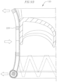
- FIG. 9 B another advantageous feature of the foam and/or cloth covered coil anchor is schematically illustrated.
- FIG. 9 B only a portion of a valve prosthesis 120 that has been expanded in a coil anchor has been illustrated, with the coil anchor 72 removed for simplicity, in order to highlight the effect of the coil anchor on a valve prosthesis 120 implanted therein.
- the frame 220 of the valve prosthesis 120 has ends that have flared radially outwards.
- the frames 220 of the valve implants 120 used in accordance with embodiments of the invention generally have a constant expanded width or diameter along the length of the implant.
- a coil anchor will generally be selected to have an inner opening that has a diameter that is smaller than the expanded diameter of the valve prosthesis 120 . Since the friction between the coil anchor 72 and the valve prosthesis 120 prevents or reduces uncoiling of the coil anchor, and therefore also prevents widening of the opening defined by the coil anchor, an interference fit is formed between the coil anchor and the portions of the valve prosthesis 120 that it comes into contact with. Generally, the valve prosthesis 120 will be centered or substantially centered on the coil anchor 72 , where the coil anchor 72 directs an inward or resistive force against a central portion of the valve prosthesis 120 , as illustrated by the arrow pointing towards the center of the prosthesis in FIG. 9 B .
- the central portion of the valve prosthesis 120 will therefore be restricted from expanding to its fully expanded size. It should be noted that either the prosthetic valve size, the size of the coil anchor, or both, can be selected so as to account for this somewhat less-than-full expansion, to avoid compromising the hemodynamics through the prosthetic valve upon implantation. Meanwhile, the top and bottom ends of the valve prosthesis 120 , which may not come into contact with the coil anchor 72 , will continue to try to expand outwards towards their fully expanded size, as further illustrated by the arrows near the ends of the prosthesis in FIG. 9 B , creating a flaring at the ends of the implant.
- FIG. 10 A shows a valve prosthesis according to an embodiment of the invention that has not been implanted in a foam or cloth covered coil anchor
- FIG. 10 B shows the valve prosthesis after it has been expanded within a foam or cloth covered coil anchor and with the anchor removed, exhibiting the flaring or widening at the ends of the prosthesis as discussed above.
- the flaring exhibited in the valve prosthesis 120 provides a number of benefits.
- the locking dynamic created between the contacting surfaces of the coil anchor and the valve prosthesis, coupled with the flared frame geometry of the prosthesis 120 combine to increase retention of the anchor within the coil anchor and the mitral valve annulus.
- the flaring and widening of the ends of the valve prosthesis 120 add a dimension to the ends of the prosthesis that serve to create an additional abutment and obstacle against dislodging of the valve from the coil anchor and potential embolization of the valve under elevated pressures within the heart.
- flaring of the sub-annular portion of the prosthetic valve i.e., the portion of the valve located in the left ventricle
- flaring of the native leaflets of the mitral valve against sub-annular portions of the coil anchor will also more securely pinch or hold the native leaflets of the mitral valve against sub-annular portions of the coil anchor, further improving retention of the implant.
- Flaring of the ends of the valve prosthesis 120 will increase contact between the prosthesis 120 and the surrounding heart tissue, such as the native mitral valve leaflets and the chordae tendineae. This could potentially lead to damage of the surrounding tissue by sharp edges or corners on the frame 220 of the valve.
- the annular cuff 224 is therefore added to the sub-annular end of the valve prosthesis 120 to protect the surrounding tissue of the heart from the flared ends of the frame 220 which could potentially dig into, cut, or otherwise damage the tissue.
- the annular cuff 224 is realized as a continuous annular ring covering at least the corners on one end of the stent frame 220 of the valve prosthesis.
- FIGS. 11 A and 11 B illustrate two alternative protective cuff arrangements.
- an alternative cuff layer 264 traces along the bottom (i.e., the sub-annular) edge of the stent frame 220 of the valve prosthesis 120 , in order to provide increased protection of the surrounding tissue from the entire bottom edge contour of the stent frame 220 .
- another alternative protective layer 284 is realized by spherical or ball-shaped protectors attached to the lowermost corners of the stent frame 220 .
- the protective layer 284 in FIG. 11 B may be desirable in some applications since, for example, a stent frame having a lower profile protective layer will be easier to collapse and deliver through a catheter or delivery sheath.
- various different protective layers are illustrated as being added only to a sub-annular end of the valve prosthesis 120 in the described embodiments, it will also be understood that similar cuff layers or other protective layers can be added to other portions of the valve prosthesis 120 in order to prevent or reduce trauma to other portions of the surrounding tissue caused by the expansion and/or flaring of the stent frame 220 .
- FIG. 12 shows a perspective view of a coil anchor according to another embodiment of the present invention.
- the coil anchor 400 includes a first coil 402 that is wound in a first circumferential direction, and a second coil 404 that is wound in a second circumferential direction opposite to the first circumferential direction. Therefore, the first and second coils 402 , 404 can be aligned next to each other along a longitudinal axis of the coils, and at least a length of each of the coils 402 , 404 nearest to one another can be aligned or pushed up against one another.
- the adjacent ends of the coils 402 , 404 are joined together at a joint 406 , which in one example is a crimp joint.
- the adjacent ends of the coils 402 , 404 are bonded or welded together, or are held together in one of various other bio-compatible means, and with or without other bio-compatible materials, that integrates the coils 402 , 404 into one single anchor or docking station.
- the coils 402 , 404 extend and wind from the joint 406 in opposite directions, and the first or upper coil 402 terminates in an upper distal end 408 , while the second or lower coil 404 terminates in a lower distal end 410 .
- the upper coil anchor 402 (or atrial anchor) is so named because the upper coil 402 will be positioned in the left atrium, above the mitral valve annulus, once deployed.
- the lower coil anchor 404 (or ventricular anchor) is so named because most of the lower coil 404 will be advanced or fed through the mitral valve at a commissure and will be positioned sub-annularly, below the mitral valve annulus, in the left ventricle once deployed.
- the coil anchor 400 can have a cover layer or layers similar to the cover layers discussed above with respect to the coil anchor 72 .
- a core of the coil anchor 400 can be covered, for example, by a fabric layer, a foam layer, or another bio-compatible material, or by a combination of such layers.
- the coil anchor 400 can initially be deployed similarly to the coil anchor 72 in previously described embodiments. As seen in FIG. 13 A , a coil guide catheter 68 is positioned in the left atrium 46 , near a mitral valve commissure 80 . The coil anchor 400 is advanced and begins extending out of the distal opening of the coil guide catheter 68 , and the distal end 410 of the lower coil 404 is directed through the valve at the commissure 80 to a sub-annular position in the left ventricle. The coil anchor 400 can be advanced via push-out force or load, can be pulled out, the sheath can be withdrawn, or the anchor 400 can be delivered from the coil guide catheter 68 using one of various other known deployment methods.
- the lower coil 404 is thereafter positioned similarly to the coil anchor 72 in previous embodiments. However, during deployment of the lower coil 404 , the upper coil 402 simultaneously advances out of the distal end of the coil guide catheter 68 , and begins unwinding in an opposite direction, and upwards into the left atrium. Due to the opposite winding directions of the upper and lower coils 402 , 404 , the central axes of the two coils can remain substantially aligned during and after deployment of the anchor 400 . Furthermore, due to the opposite winding directions, the upper and lower coils 402 , 404 will naturally curl or wind in opposite directions when they exit from the coil guide catheter 68 , and will advance away from one another along a central axis of the coil anchor 400 during deployment.
- the coil anchor 400 is advanced until the joint 406 exits the distal end of the coil guide catheter 68 . Additional adjustments of the anchor to a final desired position may further be made by the practitioner after the coil anchor 400 has exited the catheter 68 , as needed. As can be seen in FIG. 13 B , the coil anchor 400 is deployed to be arranged similarly to the coil anchor 72 in previous embodiments. In addition, since the upper and lower coils 402 , 404 are deployed and positioned at the same time, and since the coil guide catheter can remain in substantially a same position throughout deployment of the coil anchor 400 , a latter step of rotating the coil guide catheter 68 in order to release an upper portion of the anchor into the left atrium is no longer necessary, simplifying the anchor implanting procedure.
- the upper and lower coils 402 , 404 of the coil anchor 400 can be staggered, where the lower coil 404 is slightly longer than the upper coil 402 .
- the distal end 410 of the lower coil 404 is configured to exit the distal end of the coil guide catheter 68 first, for easier positioning of the distal end 410 through the valve at the commissure 80 .
- the anchor 400 can be fully advanced and positioned without adjustment, or with only minor adjustments, to the position of the coil guide catheter 68 .
- the upper and lower coils 402 , 404 are substantially the same length, or the upper coil 402 can be longer than the lower coil 404 .
- the relative lengths of the two coils of the coil anchor 400 can be adjusted based on the needs of the patient and the preferences of the practitioner, among other factors.
- different coil anchors can be deployed at the mitral position in different manners.
- it is important that the leading end, or distal end, of the sub-annular coil i.e., the portion of the coil anchor that advances through the mitral valve into the left ventricle
- the leading end, or distal end, of the sub-annular coil is directed completely around the native leaflets of the mitral valve and around the chordae tendineae, in order for the anchor to remain closely positioned to the mitral valve annulus.
- the coil may become entangled in the chordae, and/or the sub-annular portion of the coil anchor may be held under tissue where the two chordae meet, and thus be deflected farther away from the valve annulus than desired.
- Such a scenario can have negative effects, such as damage to the coil anchor and/or the chordae tendineae or the native mitral valve leaflets, or unstable anchoring or poor positioning of a valve prosthesis that is held in the coil anchor.
- FIG. 14 shows a coil anchor deployment system according to an embodiment of the invention.
- the deployment system has an arrangement similar to that of previously described embodiments, with an introducer 2 , a delivery catheter 64 , and a steering catheter or coil guide catheter 68 through which a helical anchor 72 is delivered.
- the introducer 2 is positioned through the left ventricle 10 , but in other embodiments, the introducer 2 and/or other delivery catheters can be positioned through the atrial septum, or any other access site that is suitable for delivery of a helical anchor.
- a separate catheter 18 can be included in the deployment system, and can also be fed and advanced through the introducer 2 or other sheath or cannula in the deployment system.
- a temporary ring or loop 22 is provided, which is used to corral, bundle, “lasso,” or otherwise draw the chordae tendineae 48 together prior to deployment of the helical anchor 72 .
- chordae tendineae 48 then occupy a smaller cross-sectional area in the left ventricle 10 , which facilitates easier later deployment of the distal tip of the helical anchor 72 around the chordae, and placement of the helical anchor 72 in the desired or optimal position without any chordal entanglement.
- the temporary ring or loop 22 can be, for example, a suture or a guide wire, or any other suitable thread or wire.
- the loop 22 is led or guided around the chordae tendineae 48 with for example, a grasping tool or one or more other tools introduced through the introducer 2 or through another delivery sheath or cannula.
- the loop 22 is advanced through one or more segmented guiding catheters around the chordae tendineae 48 .
- the loop 22 is closed, for example, by utilizing a clamping tool or a grasping tool, via tying, or by one of various other attachment methods, and then the segments of the guiding catheter or catheters are retracted, leaving the loop 22 in its final position around the chordae.
- the loop 22 like the helical anchor 72 , is pre-formed to have a curvature, such that the loop 22 surrounds the chordae tendineae as it is deployed.
- an opening defined by the loop 22 can further be tightened or narrowed, to further bundle or corral the chordae tendineae 48 closer together. Meanwhile, while FIG.
- any combination of catheters can be present when the loop 22 is deployed around the chordae tendineae 48 .
- the delivery catheter 64 is retracted before the coil anchor 72 is deployed, and a similar process can be followed here.
- the loop 22 can also loop around the introducer and/or one or more of the delivery or coil guide catheters.
- a distal end of the loop catheter 18 can instead be advanced through the mitral valve from the left atrium into the left ventricle, and the loop 22 can be deployed around the chordae tendineae 48 , without also bundling or corralling any additional delivery catheters or tubes therein.
- the loop 22 is removed. This can be accomplished, for example, by a release of the grasping tool if one is utilized, and/or by untying or cutting the suture, thread, or guide wire used for the loop 22 , and then removing the loop together with the other tools and catheters in the deployment system from the access site.
- a loop as described above is utilized in a coil anchor deployment system
- issues arising from a coil anchor being entangled in the chordae tendineae during deployment, or from a coil anchor being stuck between two or more chordae and being positioned incorrectly can be mitigated or prevented.
- the anchor can be more securely positioned, and a valve prosthesis can also be more securely deployed and implanted therein.
- the coils of the helical anchors are tightly wound near the mitral valve annulus.
- some of the coils of the anchor may be widened or flared outwards to make contact with, for example, the atrial wall of the left atrium.
- the number of coils both above and below the valve annulus can be varied, based on for example, properties of the native mitral valve and/or desired positioning of the valve prosthesis.
- the two coils can be prepared, modified, and/or selected separately based on a patient's anatomy or various other factors.
- other modifications to the deployment system can be employed in order to more efficiently or effectively bundle the chordae tendineae during deployment and positioning of the helical anchor.
- Various other coil shapes, lengths, and arrangements and modifications can also be made based on a wide range of considerations.
Landscapes
- Health & Medical Sciences (AREA)
- Cardiology (AREA)
- Engineering & Computer Science (AREA)
- Biomedical Technology (AREA)
- Vascular Medicine (AREA)
- Transplantation (AREA)
- Oral & Maxillofacial Surgery (AREA)
- Heart & Thoracic Surgery (AREA)
- Life Sciences & Earth Sciences (AREA)
- Animal Behavior & Ethology (AREA)
- General Health & Medical Sciences (AREA)
- Public Health (AREA)
- Veterinary Medicine (AREA)
- Mechanical Engineering (AREA)
- Prostheses (AREA)
- External Artificial Organs (AREA)
- Surgical Instruments (AREA)
Abstract
Description
Claims (13)
Priority Applications (2)
| Application Number | Priority Date | Filing Date | Title |
|---|---|---|---|
| US18/063,934 US12011348B2 (en) | 2013-08-14 | 2022-12-09 | Coiled anchor for supporting prosthetic heart valve, prosthetic heart valve, and deployment device |
| US18/665,979 US20240299160A1 (en) | 2013-08-14 | 2024-05-16 | Coiled anchor for supporting prosthetic heart valve, prosthetic heart valve, and deployment device |
Applications Claiming Priority (8)
| Application Number | Priority Date | Filing Date | Title |
|---|---|---|---|
| US201361865657P | 2013-08-14 | 2013-08-14 | |
| US201461942300P | 2014-02-20 | 2014-02-20 | |
| US201461943125P | 2014-02-21 | 2014-02-21 | |
| PCT/US2014/051095 WO2015023862A2 (en) | 2013-08-14 | 2014-08-14 | Replacement heart valve apparatus and methods |
| US14/628,020 US10052198B2 (en) | 2013-08-14 | 2015-02-20 | Coiled anchor for supporting prosthetic heart valve, prosthetic heart valve, and deployment device |
| US15/912,971 US10588742B2 (en) | 2013-08-14 | 2018-03-06 | Coiled anchor for supporting prosthetic heart valve, prosthetic heart valve, and deployment device |
| US16/814,338 US11523899B2 (en) | 2013-08-14 | 2020-03-10 | Coiled anchor for supporting prosthetic heart valve, prosthetic heart valve, and deployment device |
| US18/063,934 US12011348B2 (en) | 2013-08-14 | 2022-12-09 | Coiled anchor for supporting prosthetic heart valve, prosthetic heart valve, and deployment device |
Related Parent Applications (1)
| Application Number | Title | Priority Date | Filing Date |
|---|---|---|---|
| US16/814,338 Continuation US11523899B2 (en) | 2013-08-14 | 2020-03-10 | Coiled anchor for supporting prosthetic heart valve, prosthetic heart valve, and deployment device |
Related Child Applications (1)
| Application Number | Title | Priority Date | Filing Date |
|---|---|---|---|
| US18/665,979 Continuation US20240299160A1 (en) | 2013-08-14 | 2024-05-16 | Coiled anchor for supporting prosthetic heart valve, prosthetic heart valve, and deployment device |
Publications (2)
| Publication Number | Publication Date |
|---|---|
| US20230109200A1 US20230109200A1 (en) | 2023-04-06 |
| US12011348B2 true US12011348B2 (en) | 2024-06-18 |
Family
ID=52468811
Family Applications (7)
| Application Number | Title | Priority Date | Filing Date |
|---|---|---|---|
| US14/912,067 Active 2034-12-12 US10226330B2 (en) | 2013-08-14 | 2014-08-14 | Replacement heart valve apparatus and methods |
| US16/268,474 Active 2035-05-10 US11304797B2 (en) | 2013-08-14 | 2019-02-05 | Replacement heart valve methods |
| US16/268,464 Active 2035-05-13 US11229515B2 (en) | 2013-08-14 | 2019-02-05 | Replacement heart valve systems and methods |
| US16/268,450 Active 2035-05-05 US11234811B2 (en) | 2013-08-14 | 2019-02-05 | Replacement heart valve systems and methods |
| US18/063,934 Active 2034-10-12 US12011348B2 (en) | 2013-08-14 | 2022-12-09 | Coiled anchor for supporting prosthetic heart valve, prosthetic heart valve, and deployment device |
| US18/665,979 Pending US20240299160A1 (en) | 2013-08-14 | 2024-05-16 | Coiled anchor for supporting prosthetic heart valve, prosthetic heart valve, and deployment device |
| US19/296,062 Pending US20250359985A1 (en) | 2013-08-14 | 2025-08-11 | Replacement heart valve systems and methods |
Family Applications Before (4)
| Application Number | Title | Priority Date | Filing Date |
|---|---|---|---|
| US14/912,067 Active 2034-12-12 US10226330B2 (en) | 2013-08-14 | 2014-08-14 | Replacement heart valve apparatus and methods |
| US16/268,474 Active 2035-05-10 US11304797B2 (en) | 2013-08-14 | 2019-02-05 | Replacement heart valve methods |
| US16/268,464 Active 2035-05-13 US11229515B2 (en) | 2013-08-14 | 2019-02-05 | Replacement heart valve systems and methods |
| US16/268,450 Active 2035-05-05 US11234811B2 (en) | 2013-08-14 | 2019-02-05 | Replacement heart valve systems and methods |
Family Applications After (2)
| Application Number | Title | Priority Date | Filing Date |
|---|---|---|---|
| US18/665,979 Pending US20240299160A1 (en) | 2013-08-14 | 2024-05-16 | Coiled anchor for supporting prosthetic heart valve, prosthetic heart valve, and deployment device |
| US19/296,062 Pending US20250359985A1 (en) | 2013-08-14 | 2025-08-11 | Replacement heart valve systems and methods |
Country Status (18)
| Country | Link |
|---|---|
| US (7) | US10226330B2 (en) |
| EP (4) | EP3545906B1 (en) |
| JP (6) | JP6328242B2 (en) |
| CN (3) | CN106132352B (en) |
| BR (1) | BR112016003044B1 (en) |
| CA (2) | CA2920865C (en) |
| CR (1) | CR20160094A (en) |
| DK (1) | DK3545906T3 (en) |
| ES (2) | ES2864087T3 (en) |
| HR (1) | HRP20210197T1 (en) |
| HU (1) | HUE053121T2 (en) |
| LT (1) | LT3545906T (en) |
| PL (1) | PL3545906T3 (en) |
| PT (1) | PT3545906T (en) |
| RS (1) | RS61521B1 (en) |
| SG (2) | SG10201804437WA (en) |
| SI (1) | SI3545906T1 (en) |
| WO (1) | WO2015023862A2 (en) |
Families Citing this family (131)
| Publication number | Priority date | Publication date | Assignee | Title |
|---|---|---|---|---|
| US8323335B2 (en) | 2008-06-20 | 2012-12-04 | Edwards Lifesciences Corporation | Retaining mechanisms for prosthetic valves and methods for using |
| HUE059497T2 (en) | 2010-03-05 | 2022-11-28 | Edwards Lifesciences Corp | Support structures for heart valve prosthesis |
| US8992599B2 (en) | 2010-03-26 | 2015-03-31 | Thubrikar Aortic Valve, Inc. | Valve component, frame component and prosthetic valve device including the same for implantation in a body lumen |
| US8579964B2 (en) | 2010-05-05 | 2013-11-12 | Neovasc Inc. | Transcatheter mitral valve prosthesis |
| US8657872B2 (en) | 2010-07-19 | 2014-02-25 | Jacques Seguin | Cardiac valve repair system and methods of use |
| WO2012012761A2 (en) | 2010-07-23 | 2012-01-26 | Edwards Lifesciences Corporation | Retaining mechanisms for prosthetic valves |
| US9421098B2 (en) | 2010-12-23 | 2016-08-23 | Twelve, Inc. | System for mitral valve repair and replacement |
| US9308087B2 (en) | 2011-04-28 | 2016-04-12 | Neovasc Tiara Inc. | Sequentially deployed transcatheter mitral valve prosthesis |
| US9554897B2 (en) | 2011-04-28 | 2017-01-31 | Neovasc Tiara Inc. | Methods and apparatus for engaging a valve prosthesis with tissue |
| EP3964176B1 (en) | 2011-06-21 | 2025-05-14 | Twelve, Inc. | Prosthetic heart valve devices |
| WO2013028387A2 (en) | 2011-08-11 | 2013-02-28 | Tendyne Holdings, Inc. | Improvements for prosthetic valves and related inventions |
| US9387075B2 (en) | 2011-09-12 | 2016-07-12 | Highlife Sas | Transcatheter valve prosthesis |
| CN103917194B (en) * | 2011-09-12 | 2017-02-15 | 高品质生活简化股份公司 | Transcatheter valve prosthesis |
| US9763780B2 (en) | 2011-10-19 | 2017-09-19 | Twelve, Inc. | Devices, systems and methods for heart valve replacement |
| US9655722B2 (en) | 2011-10-19 | 2017-05-23 | Twelve, Inc. | Prosthetic heart valve devices, prosthetic mitral valves and associated systems and methods |
| US11202704B2 (en) | 2011-10-19 | 2021-12-21 | Twelve, Inc. | Prosthetic heart valve devices, prosthetic mitral valves and associated systems and methods |
| US9039757B2 (en) | 2011-10-19 | 2015-05-26 | Twelve, Inc. | Prosthetic heart valve devices, prosthetic mitral valves and associated systems and methods |
| EA201400481A1 (en) | 2011-10-19 | 2014-10-30 | Твелв, Инк. | ARTIFICIAL HEART VALVE DEVICES, ARTIFICIAL MITRAL VALVES AND RELATED SYSTEMS AND METHODS |
| CA2848334C (en) | 2011-10-19 | 2020-10-20 | Twelve, Inc. | Devices, systems and methods for heart valve replacement |
| US9078747B2 (en) | 2011-12-21 | 2015-07-14 | Edwards Lifesciences Corporation | Anchoring device for replacing or repairing a heart valve |
| CN108283534B (en) | 2012-01-31 | 2019-09-24 | 米特拉尔维尔福科技有限责任公司 | Bicuspid valve parking device and system |
| US9579198B2 (en) | 2012-03-01 | 2017-02-28 | Twelve, Inc. | Hydraulic delivery systems for prosthetic heart valve devices and associated methods |
| US9011515B2 (en) | 2012-04-19 | 2015-04-21 | Caisson Interventional, LLC | Heart valve assembly systems and methods |
| US9427315B2 (en) | 2012-04-19 | 2016-08-30 | Caisson Interventional, LLC | Valve replacement systems and methods |
| US9345573B2 (en) | 2012-05-30 | 2016-05-24 | Neovasc Tiara Inc. | Methods and apparatus for loading a prosthesis onto a delivery system |
| US9572665B2 (en) | 2013-04-04 | 2017-02-21 | Neovasc Tiara Inc. | Methods and apparatus for delivering a prosthetic valve to a beating heart |
| WO2014189974A1 (en) | 2013-05-20 | 2014-11-27 | Twelve, Inc. | Implantable heart valve devices, mitral valve repair devices and associated systems and methods |
| CN120616847A (en) | 2013-08-12 | 2025-09-12 | 米特拉尔维尔福科技有限责任公司 | Devices and methods for implanting replacement heart valves |
| CA2920865C (en) | 2013-08-14 | 2023-06-06 | Mitral Valve Technologies Sarl | Replacement heart valve apparatus and methods |
| US10195028B2 (en) | 2013-09-10 | 2019-02-05 | Edwards Lifesciences Corporation | Magnetic retaining mechanisms for prosthetic valves |
| US9050188B2 (en) | 2013-10-23 | 2015-06-09 | Caisson Interventional, LLC | Methods and systems for heart valve therapy |
| US9622863B2 (en) | 2013-11-22 | 2017-04-18 | Edwards Lifesciences Corporation | Aortic insufficiency repair device and method |
| KR102432831B1 (en) | 2014-02-04 | 2022-08-12 | 이노브하르트 에세.에레.엘레. | Prosthetic device for a heart valve |
| SG11201606836TA (en) | 2014-02-20 | 2016-09-29 | Mitral Valve Technologies Sarl | Coiled anchor for supporting prosthetic heart valve, prosthetic heart valve, and deployment device |
| CR20160366A (en) | 2014-02-21 | 2016-11-15 | Mitral Valve Tecnhnologies Sarl | DEVICES, SYSTEMS AND METHODS OF SUPPLY OF PROSTHETIC MITRAL VALVE AND ANCHORAGE DEVICE |
| EP3142604B1 (en) | 2014-05-16 | 2024-01-10 | St. Jude Medical, Cardiology Division, Inc. | Transcatheter valve with paravalvular leak sealing ring |
| US9974647B2 (en) | 2014-06-12 | 2018-05-22 | Caisson Interventional, LLC | Two stage anchor and mitral valve assembly |
| US10016272B2 (en) | 2014-09-12 | 2018-07-10 | Mitral Valve Technologies Sarl | Mitral repair and replacement devices and methods |
| US9750605B2 (en) | 2014-10-23 | 2017-09-05 | Caisson Interventional, LLC | Systems and methods for heart valve therapy |
| US9750607B2 (en) | 2014-10-23 | 2017-09-05 | Caisson Interventional, LLC | Systems and methods for heart valve therapy |
| US10231834B2 (en) | 2015-02-09 | 2019-03-19 | Edwards Lifesciences Corporation | Low profile transseptal catheter and implant system for minimally invasive valve procedure |
| US10039637B2 (en) | 2015-02-11 | 2018-08-07 | Edwards Lifesciences Corporation | Heart valve docking devices and implanting methods |
| WO2017035002A1 (en) | 2015-08-21 | 2017-03-02 | Twelve Inc. | Implantable heart valve devices, mitral valve repair devices and associated systems and methods |
| US10631977B2 (en) | 2015-08-24 | 2020-04-28 | Edwards Lifesciences Corporation | Covering and assembly method for transcatheter valve |
| EP3389557B1 (en) | 2015-12-15 | 2022-07-13 | Neovasc Tiara Inc. | Transseptal delivery system |
| WO2017117388A1 (en) | 2015-12-30 | 2017-07-06 | Caisson Interventional, LLC | Systems and methods for heart valve therapy |
| US11833034B2 (en) | 2016-01-13 | 2023-12-05 | Shifamed Holdings, Llc | Prosthetic cardiac valve devices, systems, and methods |
| US10433952B2 (en) | 2016-01-29 | 2019-10-08 | Neovasc Tiara Inc. | Prosthetic valve for avoiding obstruction of outflow |
| US10363130B2 (en) | 2016-02-05 | 2019-07-30 | Edwards Lifesciences Corporation | Devices and systems for docking a heart valve |
| EP3448316B1 (en) | 2016-04-29 | 2023-03-29 | Medtronic Vascular Inc. | Prosthetic heart valve devices with tethered anchors |
| US10758350B2 (en) * | 2016-06-06 | 2020-09-01 | Medtronic Vascular, Inc. | Transcatheter prosthetic heart valve delivery system with protective feature |
| US10828150B2 (en) | 2016-07-08 | 2020-11-10 | Edwards Lifesciences Corporation | Docking station for heart valve prosthesis |
| US12329641B2 (en) | 2016-08-26 | 2025-06-17 | Edwards Lifesciences Corporation | Heart valve docking devices and systems |
| CR20190069A (en) * | 2016-08-26 | 2019-05-14 | Edwards Lifesciences Corp | VALVES AND COUPLING SYSTEMS OF CORAZON VALVES |
| US10722359B2 (en) * | 2016-08-26 | 2020-07-28 | Edwards Lifesciences Corporation | Heart valve docking devices and systems |
| US10357361B2 (en) | 2016-09-15 | 2019-07-23 | Edwards Lifesciences Corporation | Heart valve pinch devices and delivery systems |
| US11241307B2 (en) | 2016-10-13 | 2022-02-08 | Boston Scientific Scimed, Inc. | Replacement heart valve with diaphragm |
| CN113893064A (en) | 2016-11-21 | 2022-01-07 | 内奥瓦斯克迪亚拉公司 | Methods and systems for rapid retrieval of transcatheter heart valve delivery systems |
| HUE061376T2 (en) * | 2016-12-16 | 2023-06-28 | Edwards Lifesciences Corp | Deployment systems and tools for delivering an anchoring device for a prosthetic valve |
| US10813749B2 (en) | 2016-12-20 | 2020-10-27 | Edwards Lifesciences Corporation | Docking device made with 3D woven fabric |
| ES3041130T3 (en) | 2016-12-20 | 2025-11-07 | Edwards Lifesciences Corp | Systems and mechanisms for deploying a docking device for a replacement heart valve |
| US11185406B2 (en) | 2017-01-23 | 2021-11-30 | Edwards Lifesciences Corporation | Covered prosthetic heart valve |
| US11654023B2 (en) | 2017-01-23 | 2023-05-23 | Edwards Lifesciences Corporation | Covered prosthetic heart valve |
| US11013600B2 (en) | 2017-01-23 | 2021-05-25 | Edwards Lifesciences Corporation | Covered prosthetic heart valve |
| USD867595S1 (en) | 2017-02-01 | 2019-11-19 | Edwards Lifesciences Corporation | Stent |
| EP3595588B1 (en) | 2017-03-14 | 2022-06-08 | Shape Memory Medical, Inc. | Shape memory polymer foams to seal space around valves |
| US10575950B2 (en) | 2017-04-18 | 2020-03-03 | Twelve, Inc. | Hydraulic systems for delivering prosthetic heart valve devices and associated methods |
| US10433961B2 (en) | 2017-04-18 | 2019-10-08 | Twelve, Inc. | Delivery systems with tethers for prosthetic heart valve devices and associated methods |
| IL269799B2 (en) * | 2017-04-18 | 2023-10-01 | Edwards Lifesciences Corp | Heart valve sealing devices and delivery devices therefor |
| US10702378B2 (en) | 2017-04-18 | 2020-07-07 | Twelve, Inc. | Prosthetic heart valve device and associated systems and methods |
| ES2779850T3 (en) | 2017-04-28 | 2020-08-20 | Medtentia Int Ltd Oy | Annuloplasty implant |
| US10792151B2 (en) | 2017-05-11 | 2020-10-06 | Twelve, Inc. | Delivery systems for delivering prosthetic heart valve devices and associated methods |
| US10842619B2 (en) | 2017-05-12 | 2020-11-24 | Edwards Lifesciences Corporation | Prosthetic heart valve docking assembly |
| US10646338B2 (en) | 2017-06-02 | 2020-05-12 | Twelve, Inc. | Delivery systems with telescoping capsules for deploying prosthetic heart valve devices and associated methods |
| US10709591B2 (en) | 2017-06-06 | 2020-07-14 | Twelve, Inc. | Crimping device and method for loading stents and prosthetic heart valves |
| EP3417831B2 (en) | 2017-06-19 | 2023-05-24 | HVR Cardio Oy | Delivery device for an annuloplasty implant |
| MX2019015428A (en) | 2017-06-30 | 2020-02-17 | Edwards Lifesciences Corp | Lock and release mechanisms for trans-catheter implantable devices. |
| ES2959767T3 (en) | 2017-06-30 | 2024-02-28 | Edwards Lifesciences Corp | Docking stations for transcatheter valves |
| US10786352B2 (en) | 2017-07-06 | 2020-09-29 | Twelve, Inc. | Prosthetic heart valve devices and associated systems and methods |
| US10729541B2 (en) | 2017-07-06 | 2020-08-04 | Twelve, Inc. | Prosthetic heart valve devices and associated systems and methods |
| USD890333S1 (en) | 2017-08-21 | 2020-07-14 | Edwards Lifesciences Corporation | Heart valve docking coil |
| CA3073834A1 (en) | 2017-08-25 | 2019-02-28 | Neovasc Tiara Inc. | Sequentially deployed transcatheter mitral valve prosthesis |
| US11051940B2 (en) | 2017-09-07 | 2021-07-06 | Edwards Lifesciences Corporation | Prosthetic spacer device for heart valve |
| WO2021140507A2 (en) * | 2020-01-06 | 2021-07-15 | E-Valve Systems Ltd. | Prosthetic aortic valve pacing systems |
| EP3796876B1 (en) | 2018-05-22 | 2022-07-27 | Boston Scientific Scimed, Inc. | Percutaneous papillary muscle relocation |
| CA3279869A1 (en) | 2018-08-21 | 2025-11-29 | Shifamed Holdings Llc | Prosthetic cardiac valve devices, systems, and methods |
| EP3626207A1 (en) * | 2018-09-20 | 2020-03-25 | Medtentia International Ltd Oy | A medical device for improving function of a heart valve |
| CA3115270A1 (en) * | 2018-10-05 | 2020-04-09 | Shifamed Holdings, Llc | Prosthetic cardiac valve devices, systems, and methods |
| WO2020082039A1 (en) | 2018-10-19 | 2020-04-23 | Shifamed Holdings, Llc | Adjustable medical device |
| US11737872B2 (en) | 2018-11-08 | 2023-08-29 | Neovasc Tiara Inc. | Ventricular deployment of a transcatheter mitral valve prosthesis |
| DE102018009061A1 (en) * | 2018-11-13 | 2020-05-14 | Moneera Bobaky | New biological valve prosthesis of the type under the seam ring |
| CN109350308B (en) * | 2018-12-03 | 2020-10-20 | 宁波健世生物科技有限公司 | Step-by-step clamping type valve prosthesis and conveying system thereof |
| WO2020185597A1 (en) | 2019-03-08 | 2020-09-17 | Neovasc Tiara Inc. | Retrievable prosthesis delivery system |
| EP3941391B1 (en) | 2019-03-19 | 2024-12-04 | Shifamed Holdings, LLC | Prosthetic cardiac valve devices, systems |
| CN113811265B (en) | 2019-04-01 | 2024-11-29 | 内奥瓦斯克迪亚拉公司 | Prosthetic valve capable of being deployed in a controlled manner |
| CN113924065B (en) | 2019-04-10 | 2026-01-30 | 内奥瓦斯克迪亚拉公司 | Prosthetic valve with natural blood flow |
| EP3952791A4 (en) * | 2019-04-12 | 2023-01-04 | Shifamed Holdings, LLC | DEVICES, SYSTEMS AND METHODS OF PROSTHETIC HEART VALVE PLACEMENT WITH MINIMAL FRAME |
| WO2020236931A1 (en) | 2019-05-20 | 2020-11-26 | Neovasc Tiara Inc. | Introducer with hemostasis mechanism |
| MX2021014283A (en) | 2019-06-07 | 2022-01-06 | Edwards Lifesciences Corp | Systems, devices, and methods for treating heart valves. |
| EP3986332A4 (en) | 2019-06-20 | 2023-07-19 | Neovasc Tiara Inc. | Low profile prosthetic mitral valve |
| EP3763328B1 (en) * | 2019-07-08 | 2024-08-21 | HVR Cardio Oy | A medical arrangement for introducing an object into an anatomical target position |
| EP3996630B1 (en) * | 2019-07-11 | 2025-03-19 | HVR Cardio Oy | Annuloplasty device |
| US11517425B2 (en) | 2019-07-25 | 2022-12-06 | Innovheart S.R.L. | Device for implanting a prosthesis for a heart valve and assembly procedure |
| PL4233973T3 (en) | 2019-07-25 | 2025-03-24 | Innovheart S.R.L. | DEVICE FOR PLACING GUIDE WIRES AROUND THE HEART VALVE |
| US11684473B2 (en) | 2019-07-25 | 2023-06-27 | Innovheart S.R.L. | Device for arranging guidewires around a heart valve |
| IT201900015494A1 (en) * | 2019-09-03 | 2021-03-03 | Innovheart S R L | Device for arranging guide wires around a heart valve |
| WO2021025882A1 (en) * | 2019-08-05 | 2021-02-11 | Edwards Lifesciences Corporation | Heart wall implant and method |
| US20210369454A1 (en) * | 2020-02-10 | 2021-12-02 | Synedcor LLC | System and Method for Percutaneously Delivering a Tricuspid Valve |
| EP4114313B1 (en) * | 2020-03-03 | 2025-10-01 | Shifamed Holdings, LLC | Prosthetic cardiac valve devices, systems |
| JP2020121201A (en) * | 2020-05-15 | 2020-08-13 | 株式会社大一商会 | Amusement machine |
| JP2020127885A (en) * | 2020-06-03 | 2020-08-27 | 株式会社大一商会 | Amusement machine |
| US12053371B2 (en) | 2020-08-31 | 2024-08-06 | Shifamed Holdings, Llc | Prosthetic valve delivery system |
| CN114424987A (en) * | 2020-10-29 | 2022-05-03 | 爱德华兹生命科学公司 | Apparatus and method for reducing paravalvular leakage |
| US12329635B2 (en) | 2020-12-04 | 2025-06-17 | Shifamed Holdings, Llc | Flared prosthetic cardiac valve delivery devices and systems |
| CN114795582A (en) * | 2021-01-19 | 2022-07-29 | 爱德华兹生命科学公司 | Delivery apparatus and method for prosthetic valve docking device |
| US12201521B2 (en) | 2021-03-22 | 2025-01-21 | Shifamed Holdings, Llc | Anchor position verification for prosthetic cardiac valve devices |
| US12263083B2 (en) * | 2021-05-05 | 2025-04-01 | Medtronic, Inc. | Systems for transcatheter prosthesis delivery and methods |
| CN113303947B (en) * | 2021-06-17 | 2025-01-10 | 上海臻亿医疗科技有限公司 | Anchoring device for heart valve |
| CN113730036A (en) * | 2021-09-30 | 2021-12-03 | 宁波健世科技股份有限公司 | Heart valve prosthesis capable of being anchored with autologous valve leaflet |
| CN113855329A (en) * | 2021-09-30 | 2021-12-31 | 宁波健世科技股份有限公司 | Prosthetic valve replacement system and method |
| CA3238537A1 (en) | 2021-11-17 | 2023-05-25 | Beijing Balance Medical Technology Co., Ltd. | Split type precisely-anchorable transcatheter mitral valve system |
| CN223196205U (en) * | 2021-11-19 | 2025-08-08 | 爱德华兹生命科学公司 | Docking device, protective component for docking device, and medical component |
| CN114869545A (en) * | 2022-03-31 | 2022-08-09 | 上海纽脉医疗科技股份有限公司 | Valve leaf capturing device, system and artificial heart valve |
| CN114886608A (en) * | 2022-04-01 | 2022-08-12 | 中国人民解放军陆军军医大学第二附属医院 | Channel type mitral valve prosthesis implantation system and operation method |
| CN117045394A (en) * | 2022-05-06 | 2023-11-14 | 上海臻亿医疗科技有限公司 | Valve anchor and valve system |
| CN115212009B (en) * | 2022-05-17 | 2025-07-22 | 上海纽脉医疗科技股份有限公司 | An artificial heart valve |
| CN114948345B (en) * | 2022-06-08 | 2026-01-23 | 上海汇禾医疗科技有限公司 | Heart valve positioning device, heart valve replacement assembly and implantation method |
| CN115300184A (en) * | 2022-08-10 | 2022-11-08 | 上海汇禾医疗科技有限公司 | Heart valve positioning device, artificial heart valve system, implantation system and method |
| CN115501000B (en) * | 2022-08-24 | 2026-01-23 | 上海汇禾医疗科技有限公司 | Guiding device and artificial valve anchoring method |
| CN115969580A (en) * | 2023-02-17 | 2023-04-18 | 上海纽脉医疗科技股份有限公司 | Positioning device, fishing component and artificial valve system for fishing ring |
| WO2025137375A1 (en) * | 2023-12-19 | 2025-06-26 | Shifamed Holdings, Llc | Anchor detachment devices, systems, and methods |
Citations (304)
| Publication number | Priority date | Publication date | Assignee | Title |
|---|---|---|---|---|
| US3564617A (en) | 1968-08-22 | 1971-02-23 | Lester R Sauvage | Prosthetic heart valve buried sewing ring |
| US3755823A (en) | 1971-04-23 | 1973-09-04 | Hancock Laboratories Inc | Flexible stent for heart valve |
| US4035849A (en) | 1975-11-17 | 1977-07-19 | William W. Angell | Heart valve stent and process for preparing a stented heart valve prosthesis |
| EP0103546A1 (en) | 1982-08-09 | 1984-03-21 | Domenico Iorio | Surgical instrument for implanting prosthetic heart valves or the like |
| US4490859A (en) | 1982-01-20 | 1985-01-01 | University Of Sheffield | Artificial heart valves |
| US4512338A (en) | 1983-01-25 | 1985-04-23 | Balko Alexander B | Process for restoring patency to body vessels |
| SU1271508A1 (en) | 1984-11-29 | 1986-11-23 | Горьковский государственный медицинский институт им.С.М.Кирова | Artificial heart valve |
| US4759758A (en) | 1984-12-07 | 1988-07-26 | Shlomo Gabbay | Prosthetic heart valve |
| US4777951A (en) | 1986-09-19 | 1988-10-18 | Mansfield Scientific, Inc. | Procedure and catheter instrument for treating patients for aortic stenosis |
| US4787899A (en) | 1983-12-09 | 1988-11-29 | Lazarus Harrison M | Intraluminal graft device, system and method |
| US4790843A (en) | 1986-06-16 | 1988-12-13 | Baxter Travenol Laboratories, Inc. | Prosthetic heart valve assembly |
| US4796629A (en) | 1987-06-03 | 1989-01-10 | Joseph Grayzel | Stiffened dilation balloon catheter device |
| US4856516A (en) | 1989-01-09 | 1989-08-15 | Cordis Corporation | Endovascular stent apparatus and method |
| US4878495A (en) | 1987-05-15 | 1989-11-07 | Joseph Grayzel | Valvuloplasty device with satellite expansion means |
| US4966604A (en) | 1989-01-23 | 1990-10-30 | Interventional Technologies Inc. | Expandable atherectomy cutter with flexibly bowed blades |
| US4994077A (en) | 1989-04-21 | 1991-02-19 | Dobben Richard L | Artificial heart valve for implantation in a blood vessel |
| US5059177A (en) | 1990-04-19 | 1991-10-22 | Cordis Corporation | Triple lumen balloon catheter |
| WO1991017720A1 (en) | 1990-05-18 | 1991-11-28 | Henning Rud Andersen | A valve prosthesis for implantation in the body and a catheter for implantating such valve prosthesis |
| WO1993001768A1 (en) | 1991-07-16 | 1993-02-04 | Stevens John H | Endovascular aortic valve replacement |
| US5192297A (en) | 1991-12-31 | 1993-03-09 | Medtronic, Inc. | Apparatus and method for placement and implantation of a stent |
| US5282847A (en) | 1991-02-28 | 1994-02-01 | Medtronic, Inc. | Prosthetic vascular grafts with a pleated structure |
| US5403305A (en) | 1993-04-08 | 1995-04-04 | Carbomedics, Inc. | Mitral valve prosthesis rotator |
| US5411552A (en) | 1990-05-18 | 1995-05-02 | Andersen; Henning R. | Valve prothesis for implantation in the body and a catheter for implanting such valve prothesis |
| US5443500A (en) | 1989-01-26 | 1995-08-22 | Advanced Cardiovascular Systems, Inc. | Intravascular stent |
| US5554185A (en) | 1994-07-18 | 1996-09-10 | Block; Peter C. | Inflatable prosthetic cardiovascular valve for percutaneous transluminal implantation of same |
| US5558644A (en) | 1991-07-16 | 1996-09-24 | Heartport, Inc. | Retrograde delivery catheter and method for inducing cardioplegic arrest |
| US5584803A (en) | 1991-07-16 | 1996-12-17 | Heartport, Inc. | System for cardiac procedures |
| US5591195A (en) | 1995-10-30 | 1997-01-07 | Taheri; Syde | Apparatus and method for engrafting a blood vessel |
| DE19532846A1 (en) | 1995-09-06 | 1997-03-13 | Georg Dr Berg | Valve for use in heart |
| DE19546692A1 (en) | 1995-12-14 | 1997-06-19 | Figulla Hans Reiner Prof Dr Me | Self-expandable heart valve bio-prosthesis or synthetic polyurethane valve |
| US5665115A (en) | 1992-02-21 | 1997-09-09 | Boston Scientific Technology, Inc. | Intraluminal stent |
| US5769812A (en) | 1991-07-16 | 1998-06-23 | Heartport, Inc. | System for cardiac procedures |
| EP0850607A1 (en) | 1996-12-31 | 1998-07-01 | Cordis Corporation | Valve prosthesis for implantation in body channels |
| US5800508A (en) | 1994-02-09 | 1998-09-01 | Boston Scientific Technology, Inc. | Bifurcated endoluminal prosthesis |
| US5855601A (en) | 1996-06-21 | 1999-01-05 | The Trustees Of Columbia University In The City Of New York | Artificial heart valve and method and device for implanting the same |
| US5855597A (en) | 1997-05-07 | 1999-01-05 | Iowa-India Investments Co. Limited | Stent valve and stent graft for percutaneous surgery |
| US5925063A (en) | 1997-09-26 | 1999-07-20 | Khosravi; Farhad | Coiled sheet valve, filter or occlusive device and methods of use |
| WO1999040964A1 (en) | 1998-02-16 | 1999-08-19 | Medicorp S.A. | Angioplasty and stent delivery catheter |
| WO1999047075A1 (en) | 1998-03-17 | 1999-09-23 | Medicorp S.A. | Reversible-action endoprosthesis delivery device |
| US5957949A (en) | 1997-05-01 | 1999-09-28 | World Medical Manufacturing Corp. | Percutaneous placement valve stent |
| US6027525A (en) | 1996-05-23 | 2000-02-22 | Samsung Electronics., Ltd. | Flexible self-expandable stent and method for making the same |
| DE19857887A1 (en) | 1998-12-15 | 2000-07-06 | Fraunhofer Ges Forschung | Anchoring support for a heart valve prosthesis comprises a single-piece component which is formed of rod shaped elements made of a memory metal, and has at least in part a lattice structure |
| FR2788217A1 (en) | 1999-01-12 | 2000-07-13 | Brice Letac | PROSTHETIC VALVE IMPLANTABLE BY CATHETERISM, OR SURGICAL |
| WO2000047139A1 (en) | 1999-02-10 | 2000-08-17 | Heartport, Inc. | Methods and devices for implanting cardiac valves |
| DE19907646A1 (en) | 1999-02-23 | 2000-08-24 | Georg Berg | Valve for blood vessels uses flap holders and counterpart holders on stent to latch together in place and all channeled for guide wire. |
| US6120534A (en) | 1997-10-29 | 2000-09-19 | Ruiz; Carlos E. | Endoluminal prosthesis having adjustable constriction |
| US6235042B1 (en) | 1998-09-21 | 2001-05-22 | Arteria Medical Science, Inc. | Atherectomy device |
| US6245102B1 (en) | 1997-05-07 | 2001-06-12 | Iowa-India Investments Company Ltd. | Stent, stent graft and stent valve |
| WO2001049213A2 (en) | 1999-12-31 | 2001-07-12 | Advanced Bio Prosthetic Surfaces, Ltd. | Endoluminal cardiac and venous valve prostheses and methods of manufacture and delivery thereof |
| WO2001054625A1 (en) | 2000-01-31 | 2001-08-02 | Cook Biotech Incorporated | Stent valves and uses of same |
| WO2001062189A1 (en) | 2000-02-28 | 2001-08-30 | Fraunhofer-Gesellschaft zur Förderung der angewandten Forschung e.V. | Device for fastening and anchoring cardiac valve prostheses |
| WO2001064137A1 (en) | 2000-02-28 | 2001-09-07 | Fraunhofer-Gesellschaft zur Förderung der angewandten Forschung e.V. | Anchoring system for implantable heart valve prostheses |
| WO2001076510A2 (en) | 2000-04-06 | 2001-10-18 | Edwards Lifesciences Corporation | Minimally-invasive heart valves and methods of use |
| US6306141B1 (en) | 1983-10-14 | 2001-10-23 | Medtronic, Inc. | Medical devices incorporating SIM alloy elements |
| WO2002003892A1 (en) | 2000-07-06 | 2002-01-17 | Medtentia Ab | Annuloplasty devices |
| US20020026094A1 (en) | 1993-02-22 | 2002-02-28 | Roth Alex T. | Devices for less-invasive intracardiac interventions |
| US20020032481A1 (en) | 2000-09-12 | 2002-03-14 | Shlomo Gabbay | Heart valve prosthesis and sutureless implantation of a heart valve prosthesis |
| WO2002022054A1 (en) | 2000-09-12 | 2002-03-21 | Gabbay S | Valvular prosthesis and method of using same |
| US20020045936A1 (en) | 1999-04-16 | 2002-04-18 | Riyad Moe | Heart valve leaflet |
| FR2815844A1 (en) | 2000-10-31 | 2002-05-03 | Jacques Seguin | TUBULAR SUPPORT FOR SETTING UP, BY PERCUTANEOUS, OF A REPLACEMENT HEART VALVE |
| US20020055773A1 (en) | 1999-07-12 | 2002-05-09 | Louis A. Campbell | Polymer heart valve with insert molded fabric sewing cuff |
| US6406492B1 (en) | 1999-04-08 | 2002-06-18 | Sulzer Carbomedics Inc. | Annuloplasty ring holder |
| WO2002047575A2 (en) | 2000-12-15 | 2002-06-20 | Angiomed Gmbh & Co. Medizintechnik Kg | Stent with valve |
| US6409758B2 (en) | 2000-07-27 | 2002-06-25 | Edwards Lifesciences Corporation | Heart valve holder for constricting the valve commissures and methods of use |
| US20020107535A1 (en) | 2001-02-08 | 2002-08-08 | Jeng Wei | Union for connection of artificial vessel to human vessel |
| US6432134B1 (en) | 1996-07-16 | 2002-08-13 | Anson Medical Limited | Method of producing a surgical implant |
| US20020138135A1 (en) | 2001-03-21 | 2002-09-26 | Duerig Thomas W. | Stent-based venous valves |
| US6461382B1 (en) | 2000-09-22 | 2002-10-08 | Edwards Lifesciences Corporation | Flexible heart valve having moveable commissures |
| US6482228B1 (en) | 2000-11-14 | 2002-11-19 | Troy R. Norred | Percutaneous aortic valve replacement |
| US6527979B2 (en) | 1999-08-27 | 2003-03-04 | Corazon Technologies, Inc. | Catheter systems and methods for their use in the treatment of calcified vascular occlusions |
| US20030050694A1 (en) | 2001-09-13 | 2003-03-13 | Jibin Yang | Methods and apparatuses for deploying minimally-invasive heart valves |
| WO2003028558A2 (en) | 2001-10-01 | 2003-04-10 | Ample Medical Corporation | Methods and devices for heart valve treatments |
| US20030100939A1 (en) | 2001-11-23 | 2003-05-29 | Mindguard Ltd. | Expandable delivery appliance particularly for delivering intravascular devices |
| WO2003047468A1 (en) | 2001-10-11 | 2003-06-12 | Percutaneous Valve Technologies | Implantable prosthetic valve |
| US20030158597A1 (en) | 1993-08-05 | 2003-08-21 | Quiachon Dinah B. | Multicapsule intraluminal grafting system and method |
| US20030167089A1 (en) | 2001-12-27 | 2003-09-04 | Ernest Lane | Bioprosthetic heart valve |
| US6625578B2 (en) | 1998-03-31 | 2003-09-23 | Masque Publishing, Inc. | On-line game playing with advertising |
| US20030212454A1 (en) | 2002-05-08 | 2003-11-13 | Scott Michael J. | Compressed tissue for heart valve leaflets |
| US20030225420A1 (en) | 2002-03-11 | 2003-12-04 | Wardle John L. | Surgical coils and methods of deploying |
| US6733525B2 (en) | 2001-03-23 | 2004-05-11 | Edwards Lifesciences Corporation | Rolled minimally-invasive heart valves and methods of use |
| US20040111006A1 (en) | 2002-12-17 | 2004-06-10 | Scout Medical Technologies, Llc | System and method for regulating blood pressure |
| EP1432369A1 (en) | 2001-08-31 | 2004-06-30 | Mitral Interventions | Apparatus for valve repair |
| US20040186563A1 (en) | 2003-03-18 | 2004-09-23 | Lobbi Mario M. | Minimally-invasive heart valve with cusp positioners |
| US6797002B2 (en) | 2000-02-02 | 2004-09-28 | Paul A. Spence | Heart valve repair apparatus and methods |
| US6830584B1 (en) | 1999-11-17 | 2004-12-14 | Jacques Seguin | Device for replacing a cardiac valve by percutaneous route |
| US20040260389A1 (en) | 2003-04-24 | 2004-12-23 | Cook Incorporated | Artificial valve prosthesis with improved flow dynamics |
| US6878162B2 (en) | 2002-08-30 | 2005-04-12 | Edwards Lifesciences Ag | Helical stent having improved flexibility and expandability |
| EP1521550A2 (en) | 2002-06-12 | 2005-04-13 | Mitral Interventions, Inc. | Method and apparatus for tissue connection |
| WO2005034812A1 (en) | 2003-10-02 | 2005-04-21 | Edwards Lifesciences Corporation | Implantable prosthetic valve with non-laminar flow |
| US20050119682A1 (en) | 2001-10-30 | 2005-06-02 | Eric Nguyen | Vascular exclusion catheter |
| US20050119735A1 (en) | 2002-10-21 | 2005-06-02 | Spence Paul A. | Tissue fastening systems and methods utilizing magnetic guidance |
| US20050137691A1 (en) | 2003-12-23 | 2005-06-23 | Sadra Medical | Two piece heart valve and anchor |
| US20050149178A1 (en) | 2000-07-06 | 2005-07-07 | Medtentia Ab | Annuloplasty instrument |
| US20050182486A1 (en) | 2004-02-13 | 2005-08-18 | Shlomo Gabbay | Support apparatus and heart valve prosthesis for sutureless implantation |
| WO2005084595A1 (en) | 2004-02-27 | 2005-09-15 | Cardiacmd, Inc. | Prosthetic heart valve delivery systems and methods |
| US20050228496A1 (en) | 2004-04-07 | 2005-10-13 | Medtronic, Inc. | Pharmacological delivery implement for use with cardiac repair devices |
| CN1684644A (en) | 2002-08-29 | 2005-10-19 | 米特尔溶剂有限公司 | Implantable device for controlling the inner perimeter of an anatomical hole or chamber |
| US20050234546A1 (en) | 2004-02-05 | 2005-10-20 | Alan Nugent | Transcatheter delivery of a replacement heart valve |
| WO2005102015A2 (en) | 2004-04-23 | 2005-11-03 | 3F Therapeutics, Inc. | Implantable prosthetic valve |
| US6971998B2 (en) | 2000-04-05 | 2005-12-06 | Biocardia, Inc. | Implant delivery catheter system and methods for its use |
| US20060020327A1 (en) | 2004-05-05 | 2006-01-26 | Lashinski Randall T | Nonstented heart valves with formed in situ support |
| WO2006011127A2 (en) | 2004-07-30 | 2006-02-02 | Niti Medical Technologies Ltd. | Medical devices formed from shape memory alloys displaying a stress-retained martensitic state and method for use thereof |
| US20060052867A1 (en) | 2004-09-07 | 2006-03-09 | Medtronic, Inc | Replacement prosthetic heart valve, system and method of implant |
| US20060058872A1 (en) | 2003-12-23 | 2006-03-16 | Amr Salahieh | Methods and apparatus for endovascular heart valve replacement comprising tissue grasping elements |
| US7018406B2 (en) | 1999-11-17 | 2006-03-28 | Corevalve Sa | Prosthetic valve for transluminal delivery |
| US7037334B1 (en) | 2001-04-24 | 2006-05-02 | Mitralign, Inc. | Method and apparatus for catheter-based annuloplasty using local plications |
| US20060149350A1 (en) | 2003-06-05 | 2006-07-06 | Flowmedica, Inc. | Systems and methods for performing bi-lateral interventions or diagnosis in branched body lumens |
| WO2006091163A1 (en) | 2005-02-28 | 2006-08-31 | Medtentia Ab | Devices and a kit for improving the function of a heart valve |
| US20060195185A1 (en) | 2005-02-28 | 2006-08-31 | Ernest Lane | Two piece heart valves including multiple lobe valves and methods for implanting them |
| US20060195134A1 (en) | 2005-02-28 | 2006-08-31 | Medtronic Vascular, Inc. | Device, system, and method for aiding valve annuloplasty |
| WO2006111391A1 (en) | 2005-04-21 | 2006-10-26 | Edwards Lifesciences Ag | A blood flow controlling apparatus |
| US20060265056A1 (en) | 2005-05-13 | 2006-11-23 | Corevalve, Inc. | Heart valve prosthesis and methods of manufacture and use |
| US20060271172A1 (en) | 2005-05-16 | 2006-11-30 | Hassan Tehrani | Minimally Invasive Aortic Valve Replacement |
| WO2006138173A2 (en) | 2005-06-13 | 2006-12-28 | Edwards Lifesciences Corporation | Heart valve delivery system |
| US20070010876A1 (en) | 2003-12-23 | 2007-01-11 | Amr Salahieh | Externally Expandable Heart Valve Anchor and Method |
| US20070010877A1 (en) | 2003-12-23 | 2007-01-11 | Amr Salahieh | Methods and Apparatus for Endovascularly Replacing a Heart Valve |
| US7166127B2 (en) | 2003-12-23 | 2007-01-23 | Mitralign, Inc. | Tissue fastening systems and methods utilizing magnetic guidance |
| WO2007047488A2 (en) | 2005-10-18 | 2007-04-26 | Edwards Lifesciences Corporation | Heart valve delivery system with valve catheter |
| US20070112422A1 (en) | 2005-11-16 | 2007-05-17 | Mark Dehdashtian | Transapical heart valve delivery system and method |
| WO2007067942A1 (en) | 2005-12-07 | 2007-06-14 | Arbor Surgical Technologies, Inc. | Connection systems for two piece prosthetic heart valve assemblies |
| EP1796597A2 (en) | 2004-09-14 | 2007-06-20 | Edwards Lifesciences AG | Device and method for treatment of heart valve regurgitation |
| US20070185572A1 (en) | 2006-02-09 | 2007-08-09 | Jan Otto Solem | Coiled implant for mitral valve repair |
| US20070203575A1 (en) | 2006-02-27 | 2007-08-30 | Cardiacmd, Inc., A California Corporation | Methods and devices for delivery of prosthetic heart valves and other prosthetics |
| US20070203503A1 (en) | 2003-12-23 | 2007-08-30 | Amr Salahieh | Systems and methods for delivering a medical implant |
| US20070213813A1 (en) | 2005-12-22 | 2007-09-13 | Symetis Sa | Stent-valves for valve replacement and associated methods and systems for surgery |
| US7276078B2 (en) | 2004-06-30 | 2007-10-02 | Edwards Lifesciences Pvt | Paravalvular leak detection, sealing, and prevention |
| US20070232898A1 (en) | 2006-03-31 | 2007-10-04 | Medtronic Vascular, Inc. | Telescoping Catheter With Electromagnetic Coils for Imaging and Navigation During Cardiac Procedures |
| US20070244553A1 (en) | 2006-04-12 | 2007-10-18 | Medtronic Vascular, Inc. | Annuloplasty Device Having a Helical Anchor and Methods for its Use |
| US20070265700A1 (en) | 2005-10-26 | 2007-11-15 | Eliasen Kenneth A | Safety for Mitral Valve Plug |
| US20070293808A1 (en) | 2006-04-27 | 2007-12-20 | Williams Michael S | Renal blood flow augmentation for congestive heart failure treatment |
| US20080004697A1 (en) | 2006-06-28 | 2008-01-03 | Samuel Victor Lichtenstein | Method for anchoring a mitral valve |
| WO2008005405A2 (en) | 2006-06-28 | 2008-01-10 | Lemaitre Vascular, Inc. | Non-occluding dilation device |
| US7318278B2 (en) | 2002-09-20 | 2008-01-15 | Edwards Lifesciences Corporation | Method of manufacture of a heart valve support frame |
| US20080021547A1 (en) | 2006-07-24 | 2008-01-24 | Davidson Jim A | Tissue compatible heart valve sewing ring |
| WO2008015257A2 (en) | 2006-08-02 | 2008-02-07 | Syntach Ag | Luminal implant with large expansion ratio |
| US20080077235A1 (en) | 2006-08-11 | 2008-03-27 | Kirson E D | Annuloplasty with enhanced anchoring to the annulus based on tissue healing |
| US20080114442A1 (en) | 2006-11-14 | 2008-05-15 | Medtronic Vascular, Inc. | Delivery System for Stent-Graft With Anchoring Pins |
| US7374571B2 (en) | 2001-03-23 | 2008-05-20 | Edwards Lifesciences Corporation | Rolled minimally-invasive heart valves and methods of manufacture |
| WO2008058940A1 (en) | 2006-11-13 | 2008-05-22 | Medtentia Ab | Device and method for improving function of heart valve |
| US7377941B2 (en) * | 2004-06-29 | 2008-05-27 | Micardia Corporation | Adjustable cardiac valve implant with selective dimensional adjustment |
| US7404824B1 (en) | 2002-11-15 | 2008-07-29 | Advanced Cardiovascular Systems, Inc. | Valve aptation assist device |
| WO2008091515A2 (en) | 2007-01-19 | 2008-07-31 | Medtronic, Inc. | Stented heart valve devices and methods for atrioventricular valve replacement |
| US20080200980A1 (en) | 2006-10-19 | 2008-08-21 | Kevin Robin | Profile reduction of valve implant |
| US20080200977A1 (en) | 2007-02-15 | 2008-08-21 | Cook Incorporated | Artificial Valve Prostheses with a Free Leaflet Portion |
| US20080208327A1 (en) | 2007-02-27 | 2008-08-28 | Rowe Stanton J | Method and apparatus for replacing a prosthetic valve |
| US20080228265A1 (en) | 2007-03-13 | 2008-09-18 | Mitralign, Inc. | Tissue anchors, systems and methods, and devices |
| US20080243245A1 (en) | 2004-03-11 | 2008-10-02 | Percutaneous Cardiovascular Solutions Pty Limited | Percutaneous Heart Valve Prosthesis |
| US7445632B2 (en) * | 2003-05-05 | 2008-11-04 | Rex Medical, L.P | Percutaneous aortic valve |
| US7462191B2 (en) | 2004-06-30 | 2008-12-09 | Edwards Lifesciences Pvt, Inc. | Device and method for assisting in the implantation of a prosthetic valve |
| US20090005863A1 (en) | 2006-02-16 | 2009-01-01 | Goetz Wolfgang | Minimally invasive heart valve replacement |
| WO2009033469A1 (en) | 2007-09-13 | 2009-03-19 | Georg Lutter | Heart valve stent |
| US20090088836A1 (en) | 2007-08-23 | 2009-04-02 | Direct Flow Medical, Inc. | Translumenally implantable heart valve with formed in place support |
| US20090099653A1 (en) | 2007-10-12 | 2009-04-16 | Sorin Biomedica Cardio S.R.L. | Expandable valve prosthesis with sealing mechanism |
| US7527646B2 (en) | 2000-09-20 | 2009-05-05 | Ample Medical, Inc. | Devices, systems, and methods for retaining a native heart valve leaflet |
| US20090157175A1 (en) | 2007-12-14 | 2009-06-18 | Edwards Lifesciences Corporation | Leaflet attachment frame for a prosthetic valve |
| EP2072027A1 (en) | 2007-12-21 | 2009-06-24 | Medtentia Ltd Oy | pre-annuloplasty device and method |
| US20090192601A1 (en) | 2008-01-24 | 2009-07-30 | Medtronic Vascular, Inc. | Infundibular Reducer Device Delivery System and Related Methods |
| US20090234318A1 (en) | 2007-10-19 | 2009-09-17 | Guided Delivery Systems, Inc. | Systems and methods for cardiac remodeling |
| US20090259307A1 (en) | 2006-12-05 | 2009-10-15 | Valtech Cardio, Ltd. | Segmented ring placement |
| US20090276040A1 (en) | 2008-05-01 | 2009-11-05 | Edwards Lifesciences Corporation | Device and method for replacing mitral valve |
| US20090281619A1 (en) | 2008-05-09 | 2009-11-12 | Edwards Lifesciences Corporation | Low Profile Delivery System for Transcatheter Heart Valve |
| US20090299471A1 (en) | 2005-09-07 | 2009-12-03 | Keraenen Olli | Device And Method For Improving The Function Of A Heart Valve |
| WO2009155561A2 (en) | 2008-06-20 | 2009-12-23 | Edwards Lifesciences Corporation | Retaining mechanisms for prosthetic valves |
| US20100036484A1 (en) | 2008-06-06 | 2010-02-11 | Edwards Lifesciences Corporation | Low profile transcatheter heart valve |
| US20100049313A1 (en) | 2008-08-22 | 2010-02-25 | Edwards Lifesciences Corporation | Prosthetic heart valve and delivery apparatus |
| US20100076548A1 (en) | 2008-09-19 | 2010-03-25 | Edwards Lifesciences Corporation | Prosthetic Heart Valve Configured to Receive a Percutaneous Prosthetic Heart Valve Implantation |
| US20100076549A1 (en) | 2008-09-19 | 2010-03-25 | Edwards Lifesciences Corporation | Annuloplasty Ring Configured to Receive a Percutaneous Prosthetic Heart Valve Implantation |
| US7708775B2 (en) | 2005-05-24 | 2010-05-04 | Edwards Lifesciences Corporation | Methods for rapid deployment of prosthetic heart valves |
| WO2010057262A1 (en) | 2008-11-21 | 2010-05-27 | Percutaneous Cardiovascular Solutions Pty Limited | Heart valve prosthesis and method |
| US7737060B2 (en) | 2006-03-31 | 2010-06-15 | Boston Scientific Scimed, Inc. | Medical devices containing multi-component fibers |
| US20100152839A1 (en) | 2008-10-29 | 2010-06-17 | The Regents Of The University Of Colorado, A Body Corporate | Shape Memory Polymer Prosthetic Medical Device |
| US20100161047A1 (en) | 2008-12-22 | 2010-06-24 | Valtech Cardio, Ltd. | Adjustable partial annuloplasty ring and mechanism therefor |
| US20100168844A1 (en) | 2007-01-26 | 2010-07-01 | 3F Therapeutics, Inc. | Methods and systems for reducing paravalvular leakage in heart valves |
| US7758639B2 (en) | 2003-02-03 | 2010-07-20 | Cardiac Dimensions, Inc. | Mitral valve device using conditioned shape memory alloy |
| US7780726B2 (en) | 2001-07-04 | 2010-08-24 | Medtronic, Inc. | Assembly for placing a prosthetic valve in a duct in the body |
| US20100217385A1 (en) | 2009-02-24 | 2010-08-26 | Medtronic Vascular, Inc. | One-Way Replacement Valve |
| US20100217382A1 (en) | 2009-02-25 | 2010-08-26 | Edwards Lifesciences | Mitral valve replacement with atrial anchoring |
| US7785366B2 (en) | 2005-10-26 | 2010-08-31 | Maurer Christopher W | Mitral spacer |
| WO2010121076A2 (en) | 2009-04-15 | 2010-10-21 | Cardiaq Valve Technologies, Inc. | Vascular implant and delivery system |
| US20100312333A1 (en) | 2009-04-29 | 2010-12-09 | The Cleveland Clinic Foundation | Apparatus and method for replacing a diseased cardiac valve |
| US20100318184A1 (en) | 2000-02-02 | 2010-12-16 | Spence Paul A | Heart valve repair apparatus and methods |
| US20110015729A1 (en) | 2009-07-14 | 2011-01-20 | Edwards Lifesciences Corporation | Transapical delivery system for heart valves |
| US20110098802A1 (en) | 2008-07-15 | 2011-04-28 | St. Jude Medical, Inc. | Collapsible and re-expandable prosthetic heart valve cuff designs and complementary technological applications |
| US20110106247A1 (en) | 2009-10-29 | 2011-05-05 | Valtech Cardio, Ltd. | Tissue anchor for annuloplasty device |
| US7942927B2 (en) * | 2004-03-15 | 2011-05-17 | Baker Medical Research Institute | Treating valve failure |
| US20110137397A1 (en) | 2009-12-04 | 2011-06-09 | Edwards Lifesciences Corporation | Prosthetic valve for replacing mitral valve |
| US7959672B2 (en) | 2003-12-23 | 2011-06-14 | Sadra Medical | Replacement valve and anchor |
| US7967857B2 (en) | 2006-01-27 | 2011-06-28 | Medtronic, Inc. | Gasket with spring collar for prosthetic heart valves and methods for making and using them |
| US20110178597A9 (en) | 2006-02-18 | 2011-07-21 | The Cleveland Clinic Foundation | Apparatus and method for replacing a diseased cardiac valve |
| US20110196480A1 (en) | 2009-01-22 | 2011-08-11 | Cartledge Richard G | Post-operative adjustment tool, minimally invasive attachment apparatus, and adjustable tricuspid ring |
| US20110208297A1 (en) | 2010-02-24 | 2011-08-25 | Medtronic Ventor Technologies Ltd. | Mitral Prosthesis and Methods for Implantation |
| US8016882B2 (en) | 2000-09-20 | 2011-09-13 | Mvrx, Inc. | Devices, systems, and methods for supplementing, repairing, or replacing a native heart valve leaflet |
| US20110224785A1 (en) | 2010-03-10 | 2011-09-15 | Hacohen Gil | Prosthetic mitral valve with tissue anchors |
| US8029556B2 (en) | 2006-10-04 | 2011-10-04 | Edwards Lifesciences Corporation | Method and apparatus for reshaping a ventricle |
| US20110245911A1 (en) | 2010-04-01 | 2011-10-06 | Medtronic, Inc. | Transcatheter Valve with Torsion Spring Fixation and Related Systems and Methods |
| US8052750B2 (en) | 2006-09-19 | 2011-11-08 | Medtronic Ventor Technologies Ltd | Valve prosthesis fixation techniques using sandwiching |
| US20110295361A1 (en) | 2008-02-29 | 2011-12-01 | The Florida International University Board Of Trustees | Catheter Deliverable Artificial Multi-Leaflet Heart Valve Prosthesis and Intravascular Delivery System for a Catheter Deliverable Heart Valve Prosthesis |
| US20110319989A1 (en) | 2010-05-05 | 2011-12-29 | Neovasc, Inc. | Transcatheter mitral valve prosthesis |
| US8092520B2 (en) | 2005-11-10 | 2012-01-10 | CardiAQ Technologies, Inc. | Vascular prosthesis connecting stent |
| US20120016464A1 (en) | 2010-07-19 | 2012-01-19 | Jacques Seguin | Cardiac valve repair system and methods of use |
| US20120022633A1 (en) | 2010-07-23 | 2012-01-26 | Christopher Olson | Retaining mechanisms for prosthetic valves |
| US20120022629A1 (en) | 2010-05-19 | 2012-01-26 | Direct Flow Medical, Inc. | Inflation media for implants |
| US20120053680A1 (en) | 2010-08-24 | 2012-03-01 | Bolling Steven F | Reconfiguring Heart Features |
| US20120059458A1 (en) | 2010-09-01 | 2012-03-08 | Maurice Buchbinder | Cardiac Valve Support Structure |
| US8142492B2 (en) | 2006-06-21 | 2012-03-27 | Aortx, Inc. | Prosthetic valve implantation systems |
| US20120123529A1 (en) | 2010-10-05 | 2012-05-17 | Edwards Lifesciences Corporation | Prosthetic heart valve |
| WO2012063228A1 (en) | 2010-11-12 | 2012-05-18 | Ht Consultant Di Giovanni Righini | Prosthesis for cardiovascular valve |
| US20120215236A1 (en) | 2010-06-22 | 2012-08-23 | Olympus Medical Systems Corp. | Tissue fastner production method and tissue fastener |
| US20120226349A1 (en) | 2011-03-01 | 2012-09-06 | Medtronic Ventor Technologies Ltd. | Mitral Valve Repair |
| CN102670332A (en) | 2012-05-24 | 2012-09-19 | 沛嘉医疗科技(上海)有限公司 | Novel artificial heart valve |
| US20120283820A1 (en) | 2009-09-18 | 2012-11-08 | The Regents Of The University Of California | Endovascular prosthetic heart valve replacement |
| US20120310328A1 (en) | 2011-05-31 | 2012-12-06 | Edwards Lifesciences Corporation | System and method for treating valve insufficiency or vessel dilatation |
| WO2013001339A2 (en) | 2011-06-29 | 2013-01-03 | Mitralix Ltd | Heart valve repair devices and methods |
| US20130023985A1 (en) | 2011-01-28 | 2013-01-24 | Middle Peak Medical, Inc. | Device, system, and method for transcatheter treatment of valve regurgitation |
| US8377115B2 (en) | 2009-11-16 | 2013-02-19 | Medtronic Vascular, Inc. | Implantable valve prosthesis for treating venous valve insufficiency |
| US8398708B2 (en) | 2010-03-05 | 2013-03-19 | Edwards Lifesciences Corporation | Retaining mechanisms for prosthetic valves |
| US20130114214A1 (en) | 2011-03-16 | 2013-05-09 | Koichiro Takeguchi | Television Receiver and Electronic Apparatus |
| WO2013068542A1 (en) | 2011-11-12 | 2013-05-16 | Medtentia International Ltd Oy | Device and method for improving fixation of a medical device |
| US8449606B2 (en) | 2005-10-26 | 2013-05-28 | Cardiosolutions, Inc. | Balloon mitral spacer |
| US20130190857A1 (en) | 2011-09-09 | 2013-07-25 | Endoluminal Sciences Pty Ltd. | Means for controlled sealing of endovascular devices |
| US20130190865A1 (en) | 2012-01-25 | 2013-07-25 | Boston Scientific Scimed, Inc. | Valve assembly with a bioabsorbable gasket and a replaceable valve implant |
| EP2620125A1 (en) | 2012-01-24 | 2013-07-31 | Medtentia International Ltd Oy | An arrangement, a loop-shaped support, a prosthetic heart valve and a method of repairing or replacing a native heart valve |
| US20130204311A1 (en) | 2010-05-12 | 2013-08-08 | Helical Solutions, Inc. | Implants and methods for treating cardiac arrhythmias |
| WO2013114214A2 (en) | 2012-01-31 | 2013-08-08 | Orford Holdings Sa | Mitral valve docking devices, systems and methods |
| US20130274873A1 (en) | 2012-03-22 | 2013-10-17 | Symetis Sa | Transcatheter Stent-Valves and Methods, Systems and Devices for Addressing Para-Valve Leakage |
| US20130310928A1 (en) | 2011-06-21 | 2013-11-21 | Foundry Newco Xii, Inc. | Prosthetic heart valve devices and associated systems and methods |
| US20130310917A1 (en) | 2012-05-15 | 2013-11-21 | Valve Medical Ltd. | System and method for assembling a folded percutaneous valve |
| US20130325114A1 (en) | 2011-10-19 | 2013-12-05 | Foundry Newco Xii, Inc. | Prosthetic heart valve devices, prosthetic mitral valves and associated systems and methods |
| US20130331929A1 (en) | 2011-09-09 | 2013-12-12 | Endoluminal Sciences Pty Ltd. | Means for Controlled Sealing of Endovascular Devices |
| US8652203B2 (en) | 2010-09-23 | 2014-02-18 | Cardiaq Valve Technologies, Inc. | Replacement heart valves, delivery devices and methods |
| US20140067054A1 (en) | 2012-09-06 | 2014-03-06 | Edwards Lifesciences Corporation | Heart Valve Sealing Devices |
| US20140074299A1 (en) | 2012-09-13 | 2014-03-13 | Fanuc Corporation | Themal dispalcement compensating device of machine tool |
| US20140081394A1 (en) | 2011-05-04 | 2014-03-20 | Medtentia International Ltd. Oy | Medical Device For A Cardiac Valve Implant |
| US20140155997A1 (en) | 2007-09-28 | 2014-06-05 | Peter Nicholas Braido | Collapsible-expandable prosthetic heart valves with structures for clamping native tissue |
| US20140163669A1 (en) | 2012-12-06 | 2014-06-12 | Mitralix Ltd. | Devices and methods for the replacement of the functioning of heart valves |
| US20140194981A1 (en) | 2013-01-10 | 2014-07-10 | Medtronic CV Luxembourg S.a.r.l. | Anti-Paravalvular Leakage Components for a Transcatheter Valve Prosthesis |
| US20140200661A1 (en) | 2010-09-10 | 2014-07-17 | Edwards Lifesciences Corporation | Rapidly deployable surgical heart valves |
| US8795352B2 (en) | 2008-04-15 | 2014-08-05 | Medtronic Vascular, Inc. | Devices and methods for treating valvular regurgitation |
| US8801776B2 (en) | 2008-02-25 | 2014-08-12 | Medtronic Vascular, Inc. | Infundibular reducer devices |
| US20140236287A1 (en) | 2013-02-21 | 2014-08-21 | Medtronic, Inc. | Transcatheter Valve Prosthesis and a Concurrently Delivered Sealing Component |
| US20140277419A1 (en) | 2013-03-12 | 2014-09-18 | Medtronic, Inc. | Anti-Paravalvular Leakage Component for a Transcatheter Valve Prosthesis |
| US20140277424A1 (en) | 2013-03-12 | 2014-09-18 | St. Jude Medical, Cardiology Division, Inc. | Paravalvular leak protection |
| US20140277417A1 (en) | 2013-03-14 | 2014-09-18 | St. Jude Medical, Cardiology Division, Inc. | Cuff configurations for prosthetic heart valve |
| US8840664B2 (en) | 2011-06-15 | 2014-09-23 | Edwards Lifesciences Corporation | Heart valve prosthesis anchoring device and methods |
| US20140330372A1 (en) | 2013-05-03 | 2014-11-06 | Medtronic, Inc. | Medical Devices for Implanting in a Valve and Associated Methods |
| US20140343671A1 (en) | 2011-07-15 | 2014-11-20 | Edwards Lifesciences Corporation | Perivalvular sealing for transcatheter heart valve |
| US20140358222A1 (en) | 2011-12-21 | 2014-12-04 | The Trustees Of The University Of Pennsylania | Platforms for mitral valve replacement |
| US20140358224A1 (en) | 2013-05-30 | 2014-12-04 | Tendyne Holdlings, Inc. | Six cell inner stent device for prosthetic mitral valves |
| US20140379076A1 (en) | 2013-06-25 | 2014-12-25 | Tendyne Holdings, Inc. | Halo Wire Fluid Seal Device for Prosthetic Mitral Valves |
| US20150025623A1 (en) | 2013-07-17 | 2015-01-22 | Juan F. Granada | System and method for cardiac valve repair and replacement |
| WO2015023862A2 (en) | 2013-08-14 | 2015-02-19 | Mitral Valve Technologies Sa | Replacement heart valve apparatus and methods |
| WO2015023579A1 (en) | 2013-08-12 | 2015-02-19 | Mitral Valve Technologies Sa | Apparatus and methods for implanting a replacement heart valve |
| US20150073546A1 (en) | 2007-06-04 | 2015-03-12 | St. Jude Medical, Inc. | Prosthetic heart valves |
| US20150073545A1 (en) | 2013-09-12 | 2015-03-12 | St. Jude Medical, Cardiology Division, Inc. | Stent designs for prosthetic heart valves |
| US20150190227A1 (en) | 2014-01-08 | 2015-07-09 | Cook Medical Technologies Llc | Esis heart valve support ring |
| US9078747B2 (en) | 2011-12-21 | 2015-07-14 | Edwards Lifesciences Corporation | Anchoring device for replacing or repairing a heart valve |
| US20150230921A1 (en) | 2013-08-14 | 2015-08-20 | Mitral Valve Technologies, Sarl | Coiled anchor for supporting prosthetic heart valve, prosthetic heart valve, and deployment device |
| WO2015125024A2 (en) | 2014-02-21 | 2015-08-27 | Mitral Valve Technologies Sarl | Devices, systems and methods for delivering a prosthetic mitral valve and anchoring device |
| US20150245910A1 (en) | 2012-11-20 | 2015-09-03 | Giovanni Righini | Device for the Deployment of a System of Guide Wires Within a Cardiac Chamber for Implanting a Prosthetic Heart Valve |
| US20150282931A1 (en) | 2012-11-21 | 2015-10-08 | Edwards Lifesciences Corporation | Retaining mechanisms for prosthetic heart valves |
| US9192471B2 (en) | 2007-01-08 | 2015-11-24 | Millipede, Inc. | Device for translumenal reshaping of a mitral valve annulus |
| WO2015198125A1 (en) | 2014-06-26 | 2015-12-30 | Mitralix Ltd. | Heart valve repair devices for placement in ventricle and delivery systems for implanting heart valve repair devices |
| US9237886B2 (en) | 2007-04-20 | 2016-01-19 | Medtronic, Inc. | Implant for treatment of a heart valve, in particular a mitral valve, material including such an implant, and material for insertion thereof |
| US20160015514A1 (en) | 2014-07-17 | 2016-01-21 | Millipede, Inc. | Prosthetic mitral valve with adjustable support |
| WO2016038017A1 (en) | 2014-09-08 | 2016-03-17 | Medtentia International Ltd Oy | Annuloplasty implant |
| WO2016040881A1 (en) | 2014-09-12 | 2016-03-17 | Mitral Valve Technologies Sarl | Mitral repair and replacement devices and methods |
| US20160095705A1 (en) | 2013-05-21 | 2016-04-07 | Medtentia International Ltd Oy | Medical System For Annuloplasty |
| US20160143732A1 (en) | 2013-06-19 | 2016-05-26 | Aga Medical Corporation | Collapsible valve having paravalvular leak protection |
| WO2016130820A1 (en) | 2015-02-11 | 2016-08-18 | Edwards Lifesciences Corporation | Heart valve docking devices and implanting methods |
| US9463268B2 (en) | 2010-09-07 | 2016-10-11 | Paul A. Spence | Cannula systems and methods |
| US20160346080A1 (en) | 2014-02-04 | 2016-12-01 | INNOVHEART S.r.I. | Prosthetic device for a heart valve |
| US9526572B2 (en) | 2011-04-26 | 2016-12-27 | Aperiam Medical, Inc. | Method and device for treatment of hypertension and other maladies |
| US20170007402A1 (en) | 2014-02-18 | 2017-01-12 | Medtentia International Ltd Oy | Medical Device for a Cardiac Valve Implant |
| US9597205B2 (en) | 2012-06-06 | 2017-03-21 | Magenta Medical Ltd. | Prosthetic renal valve |
| US9622863B2 (en) | 2013-11-22 | 2017-04-18 | Edwards Lifesciences Corporation | Aortic insufficiency repair device and method |
| WO2017103833A1 (en) | 2015-12-15 | 2017-06-22 | Innovheart S.R.L. | Cardiac valve prosthesis |
| US9700409B2 (en) * | 2013-11-06 | 2017-07-11 | St. Jude Medical, Cardiology Division, Inc. | Reduced profile prosthetic heart valve |
| US20170217385A1 (en) | 2016-02-03 | 2017-08-03 | Audi Ag | Circuit arrangement |
| US20170266005A1 (en) | 2014-03-15 | 2017-09-21 | Rex Medical, L.P. | Vascular device for treating venous valve insufficiency |
| US20170281337A1 (en) | 2015-09-02 | 2017-10-05 | Edwards Lifesciences Corporation | Spacer for securing a transcatheter valve to a bioprosthetic cardiac structure |
| US20170360426A1 (en) | 2010-07-21 | 2017-12-21 | Mitraltech Ltd. | Techniques for percutaneous mitral valve replacement and sealing |
| US20180000580A1 (en) | 2015-05-14 | 2018-01-04 | Dan Wallace | Replacement mitral valves |
| US20180085217A1 (en) | 2015-02-13 | 2018-03-29 | Millipede, Inc. | Valve replacement using rotational anchors |
| US20180206074A1 (en) | 2015-05-14 | 2018-07-19 | Verint Systems Ltd. | System and method for accurate location of wireless terminals using mobile interrogation device |
| US20180289481A1 (en) | 2006-04-25 | 2018-10-11 | Medtronic Vascular, Inc. | Method for stabilizing a cardiac valve annulus |
| US20180303606A1 (en) | 2015-02-12 | 2018-10-25 | Medtronic, Inc. | Integrated valve assembly and method of delivering and deploying an integrated valve assembly |
| US20180318080A1 (en) | 2013-07-10 | 2018-11-08 | Medtronic, Inc. | Helical coil mitral valve annuloplasty systems and methods |
| US10195028B2 (en) | 2013-09-10 | 2019-02-05 | Edwards Lifesciences Corporation | Magnetic retaining mechanisms for prosthetic valves |
| US10357361B2 (en) | 2016-09-15 | 2019-07-23 | Edwards Lifesciences Corporation | Heart valve pinch devices and delivery systems |
| US10463479B2 (en) | 2016-08-26 | 2019-11-05 | Edwards Lifesciences Corporation | Heart valve docking coils and systems |
| EP3395296B1 (en) | 2017-04-28 | 2019-12-18 | Medtentia International Ltd Oy | Annuloplasty implant |
| US20200261107A1 (en) * | 2011-09-28 | 2020-08-20 | Evalve, Inc. | Apparatuses and methods for cutting a tissue bridge and/or removing a heart valve clip or suture |
| US10828150B2 (en) | 2016-07-08 | 2020-11-10 | Edwards Lifesciences Corporation | Docking station for heart valve prosthesis |
| US10842625B2 (en) * | 2016-01-22 | 2020-11-24 | Medtentia International Ltd Oy | Annuloplasty implant |
| US20210212826A1 (en) | 2018-05-21 | 2021-07-15 | Medtentia International Ltd Oy | Annuloplasty device |
| US11065111B2 (en) | 2016-12-20 | 2021-07-20 | Edwards Lifesciences Corporation | Systems and mechanisms for deploying a docking device for a replacement heart valve |
| US11141273B2 (en) | 2013-03-12 | 2021-10-12 | St. Jude Medical, Cardiology Division, Inc. | Paravalvular leak occlusion device for self-expanding heart valves |
| US11185406B2 (en) | 2017-01-23 | 2021-11-30 | Edwards Lifesciences Corporation | Covered prosthetic heart valve |
| US11471282B2 (en) | 2019-03-19 | 2022-10-18 | Shifamed Holdings, Llc | Prosthetic cardiac valve devices, systems, and methods |
| US11547563B2 (en) | 2018-01-08 | 2023-01-10 | Medtentia International Ltd. Oy | Annuloplasty device |
| US20230086853A1 (en) | 2017-05-23 | 2023-03-23 | Medtentia International Ltd Oy | Annuloplasty Implant |
| US11654025B2 (en) | 2017-06-19 | 2023-05-23 | Medtentia International Ltd Oy | Delivery device for an annuloplasty implant |
| US11666441B2 (en) | 2016-12-30 | 2023-06-06 | Pipeline Medical Technologies, Inc. | Endovascular suture lock |
| US11833034B2 (en) * | 2016-01-13 | 2023-12-05 | Shifamed Holdings, Llc | Prosthetic cardiac valve devices, systems, and methods |
Family Cites Families (14)
| Publication number | Priority date | Publication date | Assignee | Title |
|---|---|---|---|---|
| US6153754A (en) | 1995-12-21 | 2000-11-28 | Albany Molecular Research, Inc. | Process for production of piperidine derivatives |
| JP3172489B2 (en) | 1998-04-01 | 2001-06-04 | 得一郎 長谷川 | Cooking containers |
| US7399271B2 (en) * | 2004-01-09 | 2008-07-15 | Cardiokinetix, Inc. | Ventricular partitioning device |
| US6663322B1 (en) | 2001-02-20 | 2003-12-16 | Jay Listle | Pier system |
| US7288111B1 (en) * | 2002-03-26 | 2007-10-30 | Thoratec Corporation | Flexible stent and method of making the same |
| US7666193B2 (en) * | 2002-06-13 | 2010-02-23 | Guided Delivery Sytems, Inc. | Delivery devices and methods for heart valve repair |
| US20050038509A1 (en) * | 2003-08-14 | 2005-02-17 | Ashe Kassem Ali | Valve prosthesis including a prosthetic leaflet |
| US7221201B2 (en) | 2004-08-11 | 2007-05-22 | Micron Technology, Inc. | Fast-locking digital phase locked loop |
| US20080208329A1 (en) | 2006-10-20 | 2008-08-28 | Gordon Bishop | Handle mechanism to adjust a medical device |
| TWI384968B (en) | 2008-12-11 | 2013-02-11 | Ind Tech Res Inst | Wound treatment apparatus |
| DE102009012177A1 (en) | 2009-02-27 | 2010-09-02 | Andreas Stihl Ag & Co. Kg | Battery operated, handheld electrical appliance |
| WO2012099979A1 (en) * | 2011-01-18 | 2012-07-26 | Loma Vista Medical, Inc. | Inflatable medical devices |
| DE102011107620A1 (en) | 2011-06-30 | 2013-01-17 | Paul Vahle Gmbh & Co. Kg | Flat coil for contactless inductive energy transfer |
| US20140277388A1 (en) * | 2013-03-12 | 2014-09-18 | Aga Medical Corporation | Biocompatible foam occlusion device for self-expanding heart valves |
-
2014
- 2014-08-14 CA CA2920865A patent/CA2920865C/en active Active
- 2014-08-14 BR BR112016003044-3A patent/BR112016003044B1/en active IP Right Grant
- 2014-08-14 JP JP2016534839A patent/JP6328242B2/en active Active
- 2014-08-14 CN CN201480056659.7A patent/CN106132352B/en active Active
- 2014-08-14 HU HUE19170015A patent/HUE053121T2/en unknown
- 2014-08-14 LT LTEP19170015.2T patent/LT3545906T/en unknown
- 2014-08-14 US US14/912,067 patent/US10226330B2/en active Active
- 2014-08-14 RS RS20210116A patent/RS61521B1/en unknown
- 2014-08-14 CA CA3194922A patent/CA3194922A1/en active Pending
- 2014-08-14 CN CN202210013124.8A patent/CN114209471A/en active Pending
- 2014-08-14 ES ES19170015T patent/ES2864087T3/en active Active
- 2014-08-14 CN CN201811242339.7A patent/CN109717988B/en active Active
- 2014-08-14 EP EP19170015.2A patent/EP3545906B1/en active Active
- 2014-08-14 PL PL19170015T patent/PL3545906T3/en unknown
- 2014-08-14 PT PT191700152T patent/PT3545906T/en unknown
- 2014-08-14 WO PCT/US2014/051095 patent/WO2015023862A2/en not_active Ceased
- 2014-08-14 CR CR20160094A patent/CR20160094A/en unknown
- 2014-08-14 ES ES20215657T patent/ES3018623T3/en active Active
- 2014-08-14 SI SI201431778T patent/SI3545906T1/en unknown
- 2014-08-14 EP EP25150443.7A patent/EP4578426A3/en active Pending
- 2014-08-14 SG SG10201804437WA patent/SG10201804437WA/en unknown
- 2014-08-14 DK DK19170015.2T patent/DK3545906T3/en active
- 2014-08-14 EP EP14836223.9A patent/EP3033048B1/en active Active
- 2014-08-14 EP EP20215657.6A patent/EP3824847B1/en active Active
- 2014-08-14 SG SG11201601035TA patent/SG11201601035TA/en unknown
-
2018
- 2018-02-01 JP JP2018016267A patent/JP6942652B2/en active Active
-
2019
- 2019-02-05 US US16/268,474 patent/US11304797B2/en active Active
- 2019-02-05 US US16/268,464 patent/US11229515B2/en active Active
- 2019-02-05 US US16/268,450 patent/US11234811B2/en active Active
-
2020
- 2020-02-21 JP JP2020028522A patent/JP7155183B2/en active Active
-
2021
- 2021-02-04 HR HRP20210197TT patent/HRP20210197T1/en unknown
-
2022
- 2022-10-04 JP JP2022160355A patent/JP7623989B2/en active Active
- 2022-12-09 US US18/063,934 patent/US12011348B2/en active Active
-
2024
- 2024-05-16 US US18/665,979 patent/US20240299160A1/en active Pending
- 2024-08-16 JP JP2024136980A patent/JP2024152868A/en active Pending
-
2025
- 2025-01-16 JP JP2025006156A patent/JP2025061398A/en active Pending
- 2025-08-11 US US19/296,062 patent/US20250359985A1/en active Pending
Patent Citations (435)
| Publication number | Priority date | Publication date | Assignee | Title |
|---|---|---|---|---|
| US3564617A (en) | 1968-08-22 | 1971-02-23 | Lester R Sauvage | Prosthetic heart valve buried sewing ring |
| US3755823A (en) | 1971-04-23 | 1973-09-04 | Hancock Laboratories Inc | Flexible stent for heart valve |
| US4035849A (en) | 1975-11-17 | 1977-07-19 | William W. Angell | Heart valve stent and process for preparing a stented heart valve prosthesis |
| US4490859A (en) | 1982-01-20 | 1985-01-01 | University Of Sheffield | Artificial heart valves |
| EP0103546A1 (en) | 1982-08-09 | 1984-03-21 | Domenico Iorio | Surgical instrument for implanting prosthetic heart valves or the like |
| US4512338A (en) | 1983-01-25 | 1985-04-23 | Balko Alexander B | Process for restoring patency to body vessels |
| US6306141B1 (en) | 1983-10-14 | 2001-10-23 | Medtronic, Inc. | Medical devices incorporating SIM alloy elements |
| US4787899A (en) | 1983-12-09 | 1988-11-29 | Lazarus Harrison M | Intraluminal graft device, system and method |
| SU1271508A1 (en) | 1984-11-29 | 1986-11-23 | Горьковский государственный медицинский институт им.С.М.Кирова | Artificial heart valve |
| US4759758A (en) | 1984-12-07 | 1988-07-26 | Shlomo Gabbay | Prosthetic heart valve |
| US4790843A (en) | 1986-06-16 | 1988-12-13 | Baxter Travenol Laboratories, Inc. | Prosthetic heart valve assembly |
| US4777951A (en) | 1986-09-19 | 1988-10-18 | Mansfield Scientific, Inc. | Procedure and catheter instrument for treating patients for aortic stenosis |
| US4878495A (en) | 1987-05-15 | 1989-11-07 | Joseph Grayzel | Valvuloplasty device with satellite expansion means |
| US4796629A (en) | 1987-06-03 | 1989-01-10 | Joseph Grayzel | Stiffened dilation balloon catheter device |
| US4856516A (en) | 1989-01-09 | 1989-08-15 | Cordis Corporation | Endovascular stent apparatus and method |
| US4966604A (en) | 1989-01-23 | 1990-10-30 | Interventional Technologies Inc. | Expandable atherectomy cutter with flexibly bowed blades |
| US5443500A (en) | 1989-01-26 | 1995-08-22 | Advanced Cardiovascular Systems, Inc. | Intravascular stent |
| US4994077A (en) | 1989-04-21 | 1991-02-19 | Dobben Richard L | Artificial heart valve for implantation in a blood vessel |
| US5059177A (en) | 1990-04-19 | 1991-10-22 | Cordis Corporation | Triple lumen balloon catheter |
| EP0592410B1 (en) | 1990-05-18 | 1995-10-11 | ANDERSEN, Henning Rud | A valve prosthesis for implantation in the body and a catheter for implantating such valve prosthesis |
| US6168614B1 (en) | 1990-05-18 | 2001-01-02 | Heartport, Inc. | Valve prosthesis for implantation in the body |
| WO1991017720A1 (en) | 1990-05-18 | 1991-11-28 | Henning Rud Andersen | A valve prosthesis for implantation in the body and a catheter for implantating such valve prosthesis |
| US7618446B2 (en) | 1990-05-18 | 2009-11-17 | Edwards Lifesciences Ag | Valve prosthesis for implantation in the body and a catheter for implanting such valve prosthesis |
| US6582462B1 (en) | 1990-05-18 | 2003-06-24 | Heartport, Inc. | Valve prosthesis for implantation in the body and a catheter for implanting such valve prosthesis |
| US5411552A (en) | 1990-05-18 | 1995-05-02 | Andersen; Henning R. | Valve prothesis for implantation in the body and a catheter for implanting such valve prothesis |
| US5840081A (en) | 1990-05-18 | 1998-11-24 | Andersen; Henning Rud | System and method for implanting cardiac valves |
| US5282847A (en) | 1991-02-28 | 1994-02-01 | Medtronic, Inc. | Prosthetic vascular grafts with a pleated structure |
| US5607464A (en) | 1991-02-28 | 1997-03-04 | Medtronic, Inc. | Prosthetic vascular graft with a pleated structure |
| US5769812A (en) | 1991-07-16 | 1998-06-23 | Heartport, Inc. | System for cardiac procedures |
| US5545214A (en) | 1991-07-16 | 1996-08-13 | Heartport, Inc. | Endovascular aortic valve replacement |
| US5558644A (en) | 1991-07-16 | 1996-09-24 | Heartport, Inc. | Retrograde delivery catheter and method for inducing cardioplegic arrest |
| US5584803A (en) | 1991-07-16 | 1996-12-17 | Heartport, Inc. | System for cardiac procedures |
| US5370685A (en) | 1991-07-16 | 1994-12-06 | Stanford Surgical Technologies, Inc. | Endovascular aortic valve replacement |
| EP0597967A1 (en) | 1991-07-16 | 1994-05-25 | Heartport, Inc. | Endovascular aortic valve replacement |
| WO1993001768A1 (en) | 1991-07-16 | 1993-02-04 | Stevens John H | Endovascular aortic valve replacement |
| US5192297A (en) | 1991-12-31 | 1993-03-09 | Medtronic, Inc. | Apparatus and method for placement and implantation of a stent |
| US5665115A (en) | 1992-02-21 | 1997-09-09 | Boston Scientific Technology, Inc. | Intraluminal stent |
| US20020026094A1 (en) | 1993-02-22 | 2002-02-28 | Roth Alex T. | Devices for less-invasive intracardiac interventions |
| US5403305A (en) | 1993-04-08 | 1995-04-04 | Carbomedics, Inc. | Mitral valve prosthesis rotator |
| US20030158597A1 (en) | 1993-08-05 | 2003-08-21 | Quiachon Dinah B. | Multicapsule intraluminal grafting system and method |
| US6302906B1 (en) | 1994-02-09 | 2001-10-16 | Boston Scientific Technology, Inc. | System for delivering a prosthesis |
| US5800508A (en) | 1994-02-09 | 1998-09-01 | Boston Scientific Technology, Inc. | Bifurcated endoluminal prosthesis |
| US5554185A (en) | 1994-07-18 | 1996-09-10 | Block; Peter C. | Inflatable prosthetic cardiovascular valve for percutaneous transluminal implantation of same |
| DE19532846A1 (en) | 1995-09-06 | 1997-03-13 | Georg Dr Berg | Valve for use in heart |
| US5591195A (en) | 1995-10-30 | 1997-01-07 | Taheri; Syde | Apparatus and method for engrafting a blood vessel |
| DE19546692A1 (en) | 1995-12-14 | 1997-06-19 | Figulla Hans Reiner Prof Dr Me | Self-expandable heart valve bio-prosthesis or synthetic polyurethane valve |
| US6027525A (en) | 1996-05-23 | 2000-02-22 | Samsung Electronics., Ltd. | Flexible self-expandable stent and method for making the same |
| US5855601A (en) | 1996-06-21 | 1999-01-05 | The Trustees Of Columbia University In The City Of New York | Artificial heart valve and method and device for implanting the same |
| US6432134B1 (en) | 1996-07-16 | 2002-08-13 | Anson Medical Limited | Method of producing a surgical implant |
| US6908481B2 (en) | 1996-12-31 | 2005-06-21 | Edwards Lifesciences Pvt, Inc. | Value prosthesis for implantation in body channels |
| WO1998029057A1 (en) | 1996-12-31 | 1998-07-09 | Cordis Corporation | Valve prosthesis for implantation in body channels |
| EP0850607A1 (en) | 1996-12-31 | 1998-07-01 | Cordis Corporation | Valve prosthesis for implantation in body channels |
| US7585321B2 (en) | 1996-12-31 | 2009-09-08 | Edwards Lifesciences Pvt, Inc. | Methods of implanting a prosthetic heart valve within a native heart valve |
| US5957949A (en) | 1997-05-01 | 1999-09-28 | World Medical Manufacturing Corp. | Percutaneous placement valve stent |
| US6245102B1 (en) | 1997-05-07 | 2001-06-12 | Iowa-India Investments Company Ltd. | Stent, stent graft and stent valve |
| US5855597A (en) | 1997-05-07 | 1999-01-05 | Iowa-India Investments Co. Limited | Stent valve and stent graft for percutaneous surgery |
| US6221091B1 (en) | 1997-09-26 | 2001-04-24 | Incept Llc | Coiled sheet valve, filter or occlusive device and methods of use |
| US5925063A (en) | 1997-09-26 | 1999-07-20 | Khosravi; Farhad | Coiled sheet valve, filter or occlusive device and methods of use |
| US6120534A (en) | 1997-10-29 | 2000-09-19 | Ruiz; Carlos E. | Endoluminal prosthesis having adjustable constriction |
| WO1999040964A1 (en) | 1998-02-16 | 1999-08-19 | Medicorp S.A. | Angioplasty and stent delivery catheter |
| WO1999047075A1 (en) | 1998-03-17 | 1999-09-23 | Medicorp S.A. | Reversible-action endoprosthesis delivery device |
| US6625578B2 (en) | 1998-03-31 | 2003-09-23 | Masque Publishing, Inc. | On-line game playing with advertising |
| US6235042B1 (en) | 1998-09-21 | 2001-05-22 | Arteria Medical Science, Inc. | Atherectomy device |
| DE19857887A1 (en) | 1998-12-15 | 2000-07-06 | Fraunhofer Ges Forschung | Anchoring support for a heart valve prosthesis comprises a single-piece component which is formed of rod shaped elements made of a memory metal, and has at least in part a lattice structure |
| WO2000041652A1 (en) | 1999-01-12 | 2000-07-20 | Brice Letac | Prosthetic heart valve implantable by catheter insertion or surgically |
| FR2788217A1 (en) | 1999-01-12 | 2000-07-13 | Brice Letac | PROSTHETIC VALVE IMPLANTABLE BY CATHETERISM, OR SURGICAL |
| WO2000047139A1 (en) | 1999-02-10 | 2000-08-17 | Heartport, Inc. | Methods and devices for implanting cardiac valves |
| US20020151970A1 (en) | 1999-02-10 | 2002-10-17 | Garrison Michi E. | Methods and devices for implanting cardiac valves |
| US6425916B1 (en) | 1999-02-10 | 2002-07-30 | Michi E. Garrison | Methods and devices for implanting cardiac valves |
| DE19907646A1 (en) | 1999-02-23 | 2000-08-24 | Georg Berg | Valve for blood vessels uses flap holders and counterpart holders on stent to latch together in place and all channeled for guide wire. |
| US6406492B1 (en) | 1999-04-08 | 2002-06-18 | Sulzer Carbomedics Inc. | Annuloplasty ring holder |
| US20020045936A1 (en) | 1999-04-16 | 2002-04-18 | Riyad Moe | Heart valve leaflet |
| US20020055773A1 (en) | 1999-07-12 | 2002-05-09 | Louis A. Campbell | Polymer heart valve with insert molded fabric sewing cuff |
| US6527979B2 (en) | 1999-08-27 | 2003-03-04 | Corazon Technologies, Inc. | Catheter systems and methods for their use in the treatment of calcified vascular occlusions |
| US6830584B1 (en) | 1999-11-17 | 2004-12-14 | Jacques Seguin | Device for replacing a cardiac valve by percutaneous route |
| US7018406B2 (en) | 1999-11-17 | 2006-03-28 | Corevalve Sa | Prosthetic valve for transluminal delivery |
| US6652578B2 (en) | 1999-12-31 | 2003-11-25 | Abps Venture One, Ltd. | Endoluminal cardiac and venous valve prostheses and methods of manufacture and delivery thereof |
| US6458153B1 (en) | 1999-12-31 | 2002-10-01 | Abps Venture One, Ltd. | Endoluminal cardiac and venous valve prostheses and methods of manufacture and delivery thereof |
| US20080125853A1 (en) | 1999-12-31 | 2008-05-29 | Abps Venture One, Ltd. | Endoluminal cardiac and venous valve prostheses and methods of manufacture and delivery thereof |
| WO2001049213A2 (en) | 1999-12-31 | 2001-07-12 | Advanced Bio Prosthetic Surfaces, Ltd. | Endoluminal cardiac and venous valve prostheses and methods of manufacture and delivery thereof |
| US7018408B2 (en) | 1999-12-31 | 2006-03-28 | Abps Venture One, Ltd. | Endoluminal cardiac and venous valve prostheses and methods of manufacture and delivery thereof |
| US20050096736A1 (en) | 2000-01-31 | 2005-05-05 | Osse Francisco J. | Percutaneous heart valve devices |
| WO2001054625A1 (en) | 2000-01-31 | 2001-08-02 | Cook Biotech Incorporated | Stent valves and uses of same |
| US20100318184A1 (en) | 2000-02-02 | 2010-12-16 | Spence Paul A | Heart valve repair apparatus and methods |
| US7166126B2 (en) | 2000-02-02 | 2007-01-23 | Paul A. Spence | Heart valve repair apparatus and methods |
| US6797002B2 (en) | 2000-02-02 | 2004-09-28 | Paul A. Spence | Heart valve repair apparatus and methods |
| US20090177278A1 (en) | 2000-02-02 | 2009-07-09 | Spence Paul A | Heart valve repair apparatus and methods |
| WO2001062189A1 (en) | 2000-02-28 | 2001-08-30 | Fraunhofer-Gesellschaft zur Förderung der angewandten Forschung e.V. | Device for fastening and anchoring cardiac valve prostheses |
| WO2001064137A1 (en) | 2000-02-28 | 2001-09-07 | Fraunhofer-Gesellschaft zur Förderung der angewandten Forschung e.V. | Anchoring system for implantable heart valve prostheses |
| US6971998B2 (en) | 2000-04-05 | 2005-12-06 | Biocardia, Inc. | Implant delivery catheter system and methods for its use |
| US6454799B1 (en) | 2000-04-06 | 2002-09-24 | Edwards Lifesciences Corporation | Minimally-invasive heart valves and methods of use |
| US20040186565A1 (en) | 2000-04-06 | 2004-09-23 | Stefan Schreck | Minimally-invasive heart valves with wireforms |
| US6767362B2 (en) | 2000-04-06 | 2004-07-27 | Edwards Lifesciences Corporation | Minimally-invasive heart valves and methods of use |
| WO2001076510A2 (en) | 2000-04-06 | 2001-10-18 | Edwards Lifesciences Corporation | Minimally-invasive heart valves and methods of use |
| US6419696B1 (en) * | 2000-07-06 | 2002-07-16 | Paul A. Spence | Annuloplasty devices and related heart valve repair methods |
| CN1714766A (en) | 2000-07-06 | 2006-01-04 | 梅德坦蒂亚公司 | Annuloplasty devices |
| EP1296618B1 (en) | 2000-07-06 | 2008-01-23 | Medtentia AB | Annuloplasty devices |
| WO2002003892A1 (en) | 2000-07-06 | 2002-01-17 | Medtentia Ab | Annuloplasty devices |
| US7077861B2 (en) | 2000-07-06 | 2006-07-18 | Medtentia Ab | Annuloplasty instrument |
| JP2004502494A (en) | 2000-07-06 | 2004-01-29 | メドテンティア アクチボラゲット | Annulus forming device |
| US20050149178A1 (en) | 2000-07-06 | 2005-07-07 | Medtentia Ab | Annuloplasty instrument |
| US6730121B2 (en) | 2000-07-06 | 2004-05-04 | Medtentia | Annuloplasty devices and related heart valve repair methods |
| US20020173841A1 (en) | 2000-07-06 | 2002-11-21 | Paul A. Spence | Annuloplasty devices and related heart valve repair methods |
| US20040167620A1 (en) | 2000-07-06 | 2004-08-26 | Medtentia | Annuloplasty devices and related heart valve repair methods |
| US6409758B2 (en) | 2000-07-27 | 2002-06-25 | Edwards Lifesciences Corporation | Heart valve holder for constricting the valve commissures and methods of use |
| WO2002022054A1 (en) | 2000-09-12 | 2002-03-21 | Gabbay S | Valvular prosthesis and method of using same |
| US20020032481A1 (en) | 2000-09-12 | 2002-03-14 | Shlomo Gabbay | Heart valve prosthesis and sutureless implantation of a heart valve prosthesis |
| US7527646B2 (en) | 2000-09-20 | 2009-05-05 | Ample Medical, Inc. | Devices, systems, and methods for retaining a native heart valve leaflet |
| US8016882B2 (en) | 2000-09-20 | 2011-09-13 | Mvrx, Inc. | Devices, systems, and methods for supplementing, repairing, or replacing a native heart valve leaflet |
| US20110319990A1 (en) | 2000-09-20 | 2011-12-29 | Mvrx, Inc. | Devices, systems, and methods for supplementing, repairing or replacing a native heart valve leaflet |
| US6461382B1 (en) | 2000-09-22 | 2002-10-08 | Edwards Lifesciences Corporation | Flexible heart valve having moveable commissures |
| FR2815844A1 (en) | 2000-10-31 | 2002-05-03 | Jacques Seguin | TUBULAR SUPPORT FOR SETTING UP, BY PERCUTANEOUS, OF A REPLACEMENT HEART VALVE |
| WO2002036048A1 (en) | 2000-10-31 | 2002-05-10 | Jacques Seguin | Tubular support for setting, by percutaneous route, a substitution cusp |
| US6482228B1 (en) | 2000-11-14 | 2002-11-19 | Troy R. Norred | Percutaneous aortic valve replacement |
| US8167935B2 (en) | 2000-11-21 | 2012-05-01 | Rex Medical, L.P. | Percutaneous aortic valve |
| WO2002047575A2 (en) | 2000-12-15 | 2002-06-20 | Angiomed Gmbh & Co. Medizintechnik Kg | Stent with valve |
| US20020107535A1 (en) | 2001-02-08 | 2002-08-08 | Jeng Wei | Union for connection of artificial vessel to human vessel |
| US20020138135A1 (en) | 2001-03-21 | 2002-09-26 | Duerig Thomas W. | Stent-based venous valves |
| US6733525B2 (en) | 2001-03-23 | 2004-05-11 | Edwards Lifesciences Corporation | Rolled minimally-invasive heart valves and methods of use |
| US7374571B2 (en) | 2001-03-23 | 2008-05-20 | Edwards Lifesciences Corporation | Rolled minimally-invasive heart valves and methods of manufacture |
| US7276084B2 (en) | 2001-03-23 | 2007-10-02 | Edwards Lifesciences Corporation | Rolled minimally invasive heart valves |
| US7037334B1 (en) | 2001-04-24 | 2006-05-02 | Mitralign, Inc. | Method and apparatus for catheter-based annuloplasty using local plications |
| US7780726B2 (en) | 2001-07-04 | 2010-08-24 | Medtronic, Inc. | Assembly for placing a prosthetic valve in a duct in the body |
| US7125421B2 (en) * | 2001-08-31 | 2006-10-24 | Mitral Interventions, Inc. | Method and apparatus for valve repair |
| EP1432369A1 (en) | 2001-08-31 | 2004-06-30 | Mitral Interventions | Apparatus for valve repair |
| US20030050694A1 (en) | 2001-09-13 | 2003-03-13 | Jibin Yang | Methods and apparatuses for deploying minimally-invasive heart valves |
| US20080140190A1 (en) | 2001-10-01 | 2008-06-12 | Ample Medical, Inc. | Methods and devices for heart valve treatments |
| WO2003028558A2 (en) | 2001-10-01 | 2003-04-10 | Ample Medical Corporation | Methods and devices for heart valve treatments |
| US7510575B2 (en) | 2001-10-11 | 2009-03-31 | Edwards Lifesciences Corporation | Implantable prosthetic valve |
| US6730118B2 (en) | 2001-10-11 | 2004-05-04 | Percutaneous Valve Technologies, Inc. | Implantable prosthetic valve |
| US6893460B2 (en) | 2001-10-11 | 2005-05-17 | Percutaneous Valve Technologies Inc. | Implantable prosthetic valve |
| WO2003047468A1 (en) | 2001-10-11 | 2003-06-12 | Percutaneous Valve Technologies | Implantable prosthetic valve |
| US7393360B2 (en) | 2001-10-11 | 2008-07-01 | Edwards Lifesciences Pvt, Inc. | Implantable prosthetic valve |
| US20050119682A1 (en) | 2001-10-30 | 2005-06-02 | Eric Nguyen | Vascular exclusion catheter |
| US20030100939A1 (en) | 2001-11-23 | 2003-05-29 | Mindguard Ltd. | Expandable delivery appliance particularly for delivering intravascular devices |
| US20030167089A1 (en) | 2001-12-27 | 2003-09-04 | Ernest Lane | Bioprosthetic heart valve |
| US20030225420A1 (en) | 2002-03-11 | 2003-12-04 | Wardle John L. | Surgical coils and methods of deploying |
| US20030212454A1 (en) | 2002-05-08 | 2003-11-13 | Scott Michael J. | Compressed tissue for heart valve leaflets |
| EP1521550A2 (en) | 2002-06-12 | 2005-04-13 | Mitral Interventions, Inc. | Method and apparatus for tissue connection |
| US7618449B2 (en) | 2002-06-12 | 2009-11-17 | Mitral Interventions | Method and apparatus for tissue connection |
| US20090276038A1 (en) | 2002-06-12 | 2009-11-05 | Tremulis William S | Method and apparatus for tissue connection |
| US7101395B2 (en) | 2002-06-12 | 2006-09-05 | Mitral Interventions, Inc. | Method and apparatus for tissue connection |
| CN1684644A (en) | 2002-08-29 | 2005-10-19 | 米特尔溶剂有限公司 | Implantable device for controlling the inner perimeter of an anatomical hole or chamber |
| US6878162B2 (en) | 2002-08-30 | 2005-04-12 | Edwards Lifesciences Ag | Helical stent having improved flexibility and expandability |
| US7318278B2 (en) | 2002-09-20 | 2008-01-15 | Edwards Lifesciences Corporation | Method of manufacture of a heart valve support frame |
| US20050119735A1 (en) | 2002-10-21 | 2005-06-02 | Spence Paul A. | Tissue fastening systems and methods utilizing magnetic guidance |
| US7404824B1 (en) | 2002-11-15 | 2008-07-29 | Advanced Cardiovascular Systems, Inc. | Valve aptation assist device |
| US20040111006A1 (en) | 2002-12-17 | 2004-06-10 | Scout Medical Technologies, Llc | System and method for regulating blood pressure |
| US7758639B2 (en) | 2003-02-03 | 2010-07-20 | Cardiac Dimensions, Inc. | Mitral valve device using conditioned shape memory alloy |
| US20040186563A1 (en) | 2003-03-18 | 2004-09-23 | Lobbi Mario M. | Minimally-invasive heart valve with cusp positioners |
| US20040260389A1 (en) | 2003-04-24 | 2004-12-23 | Cook Incorporated | Artificial valve prosthesis with improved flow dynamics |
| US7445632B2 (en) * | 2003-05-05 | 2008-11-04 | Rex Medical, L.P | Percutaneous aortic valve |
| US20060149350A1 (en) | 2003-06-05 | 2006-07-06 | Flowmedica, Inc. | Systems and methods for performing bi-lateral interventions or diagnosis in branched body lumens |
| WO2005034812A1 (en) | 2003-10-02 | 2005-04-21 | Edwards Lifesciences Corporation | Implantable prosthetic valve with non-laminar flow |
| US20060058872A1 (en) | 2003-12-23 | 2006-03-16 | Amr Salahieh | Methods and apparatus for endovascular heart valve replacement comprising tissue grasping elements |
| US20070203503A1 (en) | 2003-12-23 | 2007-08-30 | Amr Salahieh | Systems and methods for delivering a medical implant |
| US7166127B2 (en) | 2003-12-23 | 2007-01-23 | Mitralign, Inc. | Tissue fastening systems and methods utilizing magnetic guidance |
| US20070010876A1 (en) | 2003-12-23 | 2007-01-11 | Amr Salahieh | Externally Expandable Heart Valve Anchor and Method |
| US20070010877A1 (en) | 2003-12-23 | 2007-01-11 | Amr Salahieh | Methods and Apparatus for Endovascularly Replacing a Heart Valve |
| US7959672B2 (en) | 2003-12-23 | 2011-06-14 | Sadra Medical | Replacement valve and anchor |
| US20080275503A1 (en) | 2003-12-23 | 2008-11-06 | Mitralign, Inc. | Method of heart valve repair |
| US7431726B2 (en) | 2003-12-23 | 2008-10-07 | Mitralign, Inc. | Tissue fastening systems and methods utilizing magnetic guidance |
| US20050137691A1 (en) | 2003-12-23 | 2005-06-23 | Sadra Medical | Two piece heart valve and anchor |
| US20050234546A1 (en) | 2004-02-05 | 2005-10-20 | Alan Nugent | Transcatheter delivery of a replacement heart valve |
| US20050182486A1 (en) | 2004-02-13 | 2005-08-18 | Shlomo Gabbay | Support apparatus and heart valve prosthesis for sutureless implantation |
| US20050203614A1 (en) | 2004-02-27 | 2005-09-15 | Cardiacmd, Inc. | Prosthetic heart valves, scaffolding structures, and systems and methods for implantation of same |
| WO2005084595A1 (en) | 2004-02-27 | 2005-09-15 | Cardiacmd, Inc. | Prosthetic heart valve delivery systems and methods |
| US20050203617A1 (en) | 2004-02-27 | 2005-09-15 | Cardiacmd, Inc. | Prosthetic heart valves, scaffolding structures, and systems and methods for implantation of same |
| US20080243245A1 (en) | 2004-03-11 | 2008-10-02 | Percutaneous Cardiovascular Solutions Pty Limited | Percutaneous Heart Valve Prosthesis |
| US7942927B2 (en) * | 2004-03-15 | 2011-05-17 | Baker Medical Research Institute | Treating valve failure |
| US20050228496A1 (en) | 2004-04-07 | 2005-10-13 | Medtronic, Inc. | Pharmacological delivery implement for use with cardiac repair devices |
| US20060025857A1 (en) | 2004-04-23 | 2006-02-02 | Bjarne Bergheim | Implantable prosthetic valve |
| WO2005102015A2 (en) | 2004-04-23 | 2005-11-03 | 3F Therapeutics, Inc. | Implantable prosthetic valve |
| WO2005102015A3 (en) | 2004-04-23 | 2007-04-19 | 3F Therapeutics Inc | Implantable prosthetic valve |
| US20060020327A1 (en) | 2004-05-05 | 2006-01-26 | Lashinski Randall T | Nonstented heart valves with formed in situ support |
| US7377941B2 (en) * | 2004-06-29 | 2008-05-27 | Micardia Corporation | Adjustable cardiac valve implant with selective dimensional adjustment |
| US7276078B2 (en) | 2004-06-30 | 2007-10-02 | Edwards Lifesciences Pvt | Paravalvular leak detection, sealing, and prevention |
| US7462191B2 (en) | 2004-06-30 | 2008-12-09 | Edwards Lifesciences Pvt, Inc. | Device and method for assisting in the implantation of a prosthetic valve |
| WO2006011127A2 (en) | 2004-07-30 | 2006-02-02 | Niti Medical Technologies Ltd. | Medical devices formed from shape memory alloys displaying a stress-retained martensitic state and method for use thereof |
| US20060052867A1 (en) | 2004-09-07 | 2006-03-09 | Medtronic, Inc | Replacement prosthetic heart valve, system and method of implant |
| US20100198347A1 (en) | 2004-09-14 | 2010-08-05 | Edwards Lifesciences Ag | Device and method for treatment of heart valve regurgitation |
| EP1796597A2 (en) | 2004-09-14 | 2007-06-20 | Edwards Lifesciences AG | Device and method for treatment of heart valve regurgitation |
| EP1827314B1 (en) | 2004-11-19 | 2010-12-15 | Medtentia International Ltd Oy | Annuloplasty instrument |
| US7951195B2 (en) | 2004-11-19 | 2011-05-31 | Medtentia International Ltd. Oy | Annuloplasty instrument |
| US20080033542A1 (en) | 2004-11-19 | 2008-02-07 | Per Antonsson | Annuloplasty Instrument |
| US20110218621A1 (en) | 2004-11-19 | 2011-09-08 | Per Antonsson | Method Of Replacing Native Heart Valve Tissue |
| JP2008531185A (en) | 2005-02-28 | 2008-08-14 | メッドテンティア エービー | Heart valve function improvement device |
| US20060195134A1 (en) | 2005-02-28 | 2006-08-31 | Medtronic Vascular, Inc. | Device, system, and method for aiding valve annuloplasty |
| US20100318183A1 (en) | 2005-02-28 | 2010-12-16 | Keraenen Olli | System For Improving The Function Of A Heart Valve |
| US9180006B2 (en) * | 2005-02-28 | 2015-11-10 | Medtentia Ab | Devices and a kit for improving the function of a heart valve |
| WO2006091163A1 (en) | 2005-02-28 | 2006-08-31 | Medtentia Ab | Devices and a kit for improving the function of a heart valve |
| US20080208330A1 (en) | 2005-02-28 | 2008-08-28 | Olli Keranen | Devices and a Kit for Improving the Function of a Heart Valve |
| US7955385B2 (en) | 2005-02-28 | 2011-06-07 | Medtronic Vascular, Inc. | Device, system, and method for aiding valve annuloplasty |
| US20060195185A1 (en) | 2005-02-28 | 2006-08-31 | Ernest Lane | Two piece heart valves including multiple lobe valves and methods for implanting them |
| WO2006111391A1 (en) | 2005-04-21 | 2006-10-26 | Edwards Lifesciences Ag | A blood flow controlling apparatus |
| US20120259409A1 (en) | 2005-05-13 | 2012-10-11 | Medtronic Corevalve, Inc. | Heart Valve Prosthesis and Methods of Manufacture and Use |
| US20060265056A1 (en) | 2005-05-13 | 2006-11-23 | Corevalve, Inc. | Heart valve prosthesis and methods of manufacture and use |
| US20060271172A1 (en) | 2005-05-16 | 2006-11-30 | Hassan Tehrani | Minimally Invasive Aortic Valve Replacement |
| US20130317598A1 (en) | 2005-05-24 | 2013-11-28 | Edwards Lifesciences Corporation | Rapid deployment prosthetic heart valves |
| US7708775B2 (en) | 2005-05-24 | 2010-05-04 | Edwards Lifesciences Corporation | Methods for rapid deployment of prosthetic heart valves |
| US20070005131A1 (en) | 2005-06-13 | 2007-01-04 | Taylor David M | Heart valve delivery system |
| WO2006138173A2 (en) | 2005-06-13 | 2006-12-28 | Edwards Lifesciences Corporation | Heart valve delivery system |
| US20100331973A1 (en) | 2005-09-07 | 2010-12-30 | Keraenen Olli | Device And Method For Improving The Function Of A Heart Valve |
| US8128691B2 (en) * | 2005-09-07 | 2012-03-06 | Medtentia International Ltd. Oy | Device and method for improving the function of a heart valve |
| US20150335428A1 (en) | 2005-09-07 | 2015-11-26 | Medtentia International Ltd Oy | Device And Method For Improving The Function Of A Heart Valve |
| US20090299471A1 (en) | 2005-09-07 | 2009-12-03 | Keraenen Olli | Device And Method For Improving The Function Of A Heart Valve |
| US9119718B2 (en) | 2005-09-07 | 2015-09-01 | Medtentia International Ltd Oy | Device and method for improving the function of a heart valve |
| WO2007047488A2 (en) | 2005-10-18 | 2007-04-26 | Edwards Lifesciences Corporation | Heart valve delivery system with valve catheter |
| US8167932B2 (en) | 2005-10-18 | 2012-05-01 | Edwards Lifesciences Corporation | Heart valve delivery system with valve catheter |
| US7785366B2 (en) | 2005-10-26 | 2010-08-31 | Maurer Christopher W | Mitral spacer |
| US20070265700A1 (en) | 2005-10-26 | 2007-11-15 | Eliasen Kenneth A | Safety for Mitral Valve Plug |
| US8449606B2 (en) | 2005-10-26 | 2013-05-28 | Cardiosolutions, Inc. | Balloon mitral spacer |
| US8092520B2 (en) | 2005-11-10 | 2012-01-10 | CardiAQ Technologies, Inc. | Vascular prosthesis connecting stent |
| US20070112422A1 (en) | 2005-11-16 | 2007-05-17 | Mark Dehdashtian | Transapical heart valve delivery system and method |
| WO2007067942A1 (en) | 2005-12-07 | 2007-06-14 | Arbor Surgical Technologies, Inc. | Connection systems for two piece prosthetic heart valve assemblies |
| US20070213813A1 (en) | 2005-12-22 | 2007-09-13 | Symetis Sa | Stent-valves for valve replacement and associated methods and systems for surgery |
| US7967857B2 (en) | 2006-01-27 | 2011-06-28 | Medtronic, Inc. | Gasket with spring collar for prosthetic heart valves and methods for making and using them |
| US20070185572A1 (en) | 2006-02-09 | 2007-08-09 | Jan Otto Solem | Coiled implant for mitral valve repair |
| US7637946B2 (en) | 2006-02-09 | 2009-12-29 | Edwards Lifesciences Corporation | Coiled implant for mitral valve repair |
| WO2007097983A2 (en) | 2006-02-14 | 2007-08-30 | Sadra Medical, Inc. | Systems and methods for delivering a medical implant |
| US20090005863A1 (en) | 2006-02-16 | 2009-01-01 | Goetz Wolfgang | Minimally invasive heart valve replacement |
| US8685086B2 (en) | 2006-02-18 | 2014-04-01 | The Cleveland Clinic Foundation | Apparatus and method for replacing a diseased cardiac valve |
| US20110178597A9 (en) | 2006-02-18 | 2011-07-21 | The Cleveland Clinic Foundation | Apparatus and method for replacing a diseased cardiac valve |
| US20070203575A1 (en) | 2006-02-27 | 2007-08-30 | Cardiacmd, Inc., A California Corporation | Methods and devices for delivery of prosthetic heart valves and other prosthetics |
| US7737060B2 (en) | 2006-03-31 | 2010-06-15 | Boston Scientific Scimed, Inc. | Medical devices containing multi-component fibers |
| US20070232898A1 (en) | 2006-03-31 | 2007-10-04 | Medtronic Vascular, Inc. | Telescoping Catheter With Electromagnetic Coils for Imaging and Navigation During Cardiac Procedures |
| US20070244553A1 (en) | 2006-04-12 | 2007-10-18 | Medtronic Vascular, Inc. | Annuloplasty Device Having a Helical Anchor and Methods for its Use |
| US20180289481A1 (en) | 2006-04-25 | 2018-10-11 | Medtronic Vascular, Inc. | Method for stabilizing a cardiac valve annulus |
| US20070293808A1 (en) | 2006-04-27 | 2007-12-20 | Williams Michael S | Renal blood flow augmentation for congestive heart failure treatment |
| US8142492B2 (en) | 2006-06-21 | 2012-03-27 | Aortx, Inc. | Prosthetic valve implantation systems |
| US20120150287A1 (en) | 2006-06-21 | 2012-06-14 | Forster David C | Prosthetic Valve Implantation Systems |
| US8672998B2 (en) | 2006-06-28 | 2014-03-18 | Kardium Inc. | Method for anchoring a mitral valve |
| WO2008005405A2 (en) | 2006-06-28 | 2008-01-10 | Lemaitre Vascular, Inc. | Non-occluding dilation device |
| US8449605B2 (en) | 2006-06-28 | 2013-05-28 | Kardium Inc. | Method for anchoring a mitral valve |
| US20080004697A1 (en) | 2006-06-28 | 2008-01-03 | Samuel Victor Lichtenstein | Method for anchoring a mitral valve |
| US20080021547A1 (en) | 2006-07-24 | 2008-01-24 | Davidson Jim A | Tissue compatible heart valve sewing ring |
| WO2008015257A2 (en) | 2006-08-02 | 2008-02-07 | Syntach Ag | Luminal implant with large expansion ratio |
| US20080077235A1 (en) | 2006-08-11 | 2008-03-27 | Kirson E D | Annuloplasty with enhanced anchoring to the annulus based on tissue healing |
| US8052750B2 (en) | 2006-09-19 | 2011-11-08 | Medtronic Ventor Technologies Ltd | Valve prosthesis fixation techniques using sandwiching |
| US20110288634A1 (en) | 2006-09-19 | 2011-11-24 | Medtronic Vascular, Inc. | Valve Prosthetic Fixation Techniques Using Sandwiching |
| US8029556B2 (en) | 2006-10-04 | 2011-10-04 | Edwards Lifesciences Corporation | Method and apparatus for reshaping a ventricle |
| US20080200980A1 (en) | 2006-10-19 | 2008-08-21 | Kevin Robin | Profile reduction of valve implant |
| US8663322B2 (en) * | 2006-11-13 | 2014-03-04 | Medtentia International Ltd. Oy | Device and method for improving function of heart valve |
| US8734507B2 (en) | 2006-11-13 | 2014-05-27 | Medtentia International Ltd. Oy | Device and method for improving function of heart valve |
| US20100145440A1 (en) | 2006-11-13 | 2010-06-10 | Keraenen Olli | Device And Method For Improving Function Of Heart Valve |
| US20120316643A1 (en) | 2006-11-13 | 2012-12-13 | Keraenen Olli | Device and Method For Improving Function Of Heart Valve |
| CN101588771A (en) | 2006-11-13 | 2009-11-25 | 梅德坦蒂亚公司 | Devices and methods for improving heart valve function |
| WO2008058940A1 (en) | 2006-11-13 | 2008-05-22 | Medtentia Ab | Device and method for improving function of heart valve |
| US7655034B2 (en) | 2006-11-14 | 2010-02-02 | Medtronic Vascular, Inc. | Stent-graft with anchoring pins |
| US20080114442A1 (en) | 2006-11-14 | 2008-05-15 | Medtronic Vascular, Inc. | Delivery System for Stent-Graft With Anchoring Pins |
| US20090259307A1 (en) | 2006-12-05 | 2009-10-15 | Valtech Cardio, Ltd. | Segmented ring placement |
| US9192471B2 (en) | 2007-01-08 | 2015-11-24 | Millipede, Inc. | Device for translumenal reshaping of a mitral valve annulus |
| WO2008091515A2 (en) | 2007-01-19 | 2008-07-31 | Medtronic, Inc. | Stented heart valve devices and methods for atrioventricular valve replacement |
| US20100168844A1 (en) | 2007-01-26 | 2010-07-01 | 3F Therapeutics, Inc. | Methods and systems for reducing paravalvular leakage in heart valves |
| US20080200977A1 (en) | 2007-02-15 | 2008-08-21 | Cook Incorporated | Artificial Valve Prostheses with a Free Leaflet Portion |
| US9095434B2 (en) | 2007-02-27 | 2015-08-04 | Edwards Lifesciences Corporation | Method and apparatus for replacing a prosthetic valve |
| US20080208327A1 (en) | 2007-02-27 | 2008-08-28 | Rowe Stanton J | Method and apparatus for replacing a prosthetic valve |
| US20080228265A1 (en) | 2007-03-13 | 2008-09-18 | Mitralign, Inc. | Tissue anchors, systems and methods, and devices |
| US9237886B2 (en) | 2007-04-20 | 2016-01-19 | Medtronic, Inc. | Implant for treatment of a heart valve, in particular a mitral valve, material including such an implant, and material for insertion thereof |
| US20150073546A1 (en) | 2007-06-04 | 2015-03-12 | St. Jude Medical, Inc. | Prosthetic heart valves |
| US20090088836A1 (en) | 2007-08-23 | 2009-04-02 | Direct Flow Medical, Inc. | Translumenally implantable heart valve with formed in place support |
| WO2009033469A1 (en) | 2007-09-13 | 2009-03-19 | Georg Lutter | Heart valve stent |
| US20140155997A1 (en) | 2007-09-28 | 2014-06-05 | Peter Nicholas Braido | Collapsible-expandable prosthetic heart valves with structures for clamping native tissue |
| US20090099653A1 (en) | 2007-10-12 | 2009-04-16 | Sorin Biomedica Cardio S.R.L. | Expandable valve prosthesis with sealing mechanism |
| US20150335430A1 (en) | 2007-10-19 | 2015-11-26 | Guided Delivery Systems Inc. | Systems and methods for cardiac remodeling |
| US20090234318A1 (en) | 2007-10-19 | 2009-09-17 | Guided Delivery Systems, Inc. | Systems and methods for cardiac remodeling |
| US20090157175A1 (en) | 2007-12-14 | 2009-06-18 | Edwards Lifesciences Corporation | Leaflet attachment frame for a prosthetic valve |
| WO2009080801A1 (en) | 2007-12-21 | 2009-07-02 | Medtentia Ltd Oy | Cardiac valve downsizing device and method |
| EP2072027A1 (en) | 2007-12-21 | 2009-06-24 | Medtentia Ltd Oy | pre-annuloplasty device and method |
| US20100331971A1 (en) | 2007-12-21 | 2010-12-30 | Keraenen Olli | Cardiac Valve Downsizing Device And Method |
| US20090192601A1 (en) | 2008-01-24 | 2009-07-30 | Medtronic Vascular, Inc. | Infundibular Reducer Device Delivery System and Related Methods |
| US8801776B2 (en) | 2008-02-25 | 2014-08-12 | Medtronic Vascular, Inc. | Infundibular reducer devices |
| US20110295361A1 (en) | 2008-02-29 | 2011-12-01 | The Florida International University Board Of Trustees | Catheter Deliverable Artificial Multi-Leaflet Heart Valve Prosthesis and Intravascular Delivery System for a Catheter Deliverable Heart Valve Prosthesis |
| US8795352B2 (en) | 2008-04-15 | 2014-08-05 | Medtronic Vascular, Inc. | Devices and methods for treating valvular regurgitation |
| WO2009134701A2 (en) | 2008-05-01 | 2009-11-05 | Edwards Lifesciences Corporation | Device and method for replacing mitral valve |
| US20090276040A1 (en) | 2008-05-01 | 2009-11-05 | Edwards Lifesciences Corporation | Device and method for replacing mitral valve |
| US20090281619A1 (en) | 2008-05-09 | 2009-11-12 | Edwards Lifesciences Corporation | Low Profile Delivery System for Transcatheter Heart Valve |
| US7993394B2 (en) | 2008-06-06 | 2011-08-09 | Ilia Hariton | Low profile transcatheter heart valve |
| US20100036484A1 (en) | 2008-06-06 | 2010-02-11 | Edwards Lifesciences Corporation | Low profile transcatheter heart valve |
| US8236049B2 (en) | 2008-06-20 | 2012-08-07 | Edwards Lifesciences Corporation | Multipiece prosthetic mitral valve and method |
| US8323335B2 (en) | 2008-06-20 | 2012-12-04 | Edwards Lifesciences Corporation | Retaining mechanisms for prosthetic valves and methods for using |
| US20090319037A1 (en) | 2008-06-20 | 2009-12-24 | Edwards Lifesciences Corporation | Retaining mechanisms for prosthetic valves |
| WO2009155561A2 (en) | 2008-06-20 | 2009-12-23 | Edwards Lifesciences Corporation | Retaining mechanisms for prosthetic valves |
| US20140350667A1 (en) | 2008-07-15 | 2014-11-27 | St. Jude Medical, Inc. | Collapsible and re-expandable prosthetic heart valve cuff designs and complementary technological applications |
| US20110098802A1 (en) | 2008-07-15 | 2011-04-28 | St. Jude Medical, Inc. | Collapsible and re-expandable prosthetic heart valve cuff designs and complementary technological applications |
| US20100049313A1 (en) | 2008-08-22 | 2010-02-25 | Edwards Lifesciences Corporation | Prosthetic heart valve and delivery apparatus |
| US9314335B2 (en) | 2008-09-19 | 2016-04-19 | Edwards Lifesciences Corporation | Prosthetic heart valve configured to receive a percutaneous prosthetic heart valve implantation |
| US20100076548A1 (en) | 2008-09-19 | 2010-03-25 | Edwards Lifesciences Corporation | Prosthetic Heart Valve Configured to Receive a Percutaneous Prosthetic Heart Valve Implantation |
| US20100076549A1 (en) | 2008-09-19 | 2010-03-25 | Edwards Lifesciences Corporation | Annuloplasty Ring Configured to Receive a Percutaneous Prosthetic Heart Valve Implantation |
| US20100152839A1 (en) | 2008-10-29 | 2010-06-17 | The Regents Of The University Of Colorado, A Body Corporate | Shape Memory Polymer Prosthetic Medical Device |
| WO2010057262A1 (en) | 2008-11-21 | 2010-05-27 | Percutaneous Cardiovascular Solutions Pty Limited | Heart valve prosthesis and method |
| US20100161047A1 (en) | 2008-12-22 | 2010-06-24 | Valtech Cardio, Ltd. | Adjustable partial annuloplasty ring and mechanism therefor |
| US20110196480A1 (en) | 2009-01-22 | 2011-08-11 | Cartledge Richard G | Post-operative adjustment tool, minimally invasive attachment apparatus, and adjustable tricuspid ring |
| US20100217385A1 (en) | 2009-02-24 | 2010-08-26 | Medtronic Vascular, Inc. | One-Way Replacement Valve |
| US20100217382A1 (en) | 2009-02-25 | 2010-08-26 | Edwards Lifesciences | Mitral valve replacement with atrial anchoring |
| WO2010121076A2 (en) | 2009-04-15 | 2010-10-21 | Cardiaq Valve Technologies, Inc. | Vascular implant and delivery system |
| US20100312333A1 (en) | 2009-04-29 | 2010-12-09 | The Cleveland Clinic Foundation | Apparatus and method for replacing a diseased cardiac valve |
| US20110015729A1 (en) | 2009-07-14 | 2011-01-20 | Edwards Lifesciences Corporation | Transapical delivery system for heart valves |
| US20120283820A1 (en) | 2009-09-18 | 2012-11-08 | The Regents Of The University Of California | Endovascular prosthetic heart valve replacement |
| US20180318073A1 (en) | 2009-09-18 | 2018-11-08 | The Regents Of The University Of California | Endovascular prosthetic heart valve replacement |
| US20110106247A1 (en) | 2009-10-29 | 2011-05-05 | Valtech Cardio, Ltd. | Tissue anchor for annuloplasty device |
| US8377115B2 (en) | 2009-11-16 | 2013-02-19 | Medtronic Vascular, Inc. | Implantable valve prosthesis for treating venous valve insufficiency |
| US8449599B2 (en) | 2009-12-04 | 2013-05-28 | Edwards Lifesciences Corporation | Prosthetic valve for replacing mitral valve |
| US20120323316A1 (en) | 2009-12-04 | 2012-12-20 | Edwards Lifesciences Corporation | Prosthetic apparatus for implantation at mitral valve |
| US8986373B2 (en) | 2009-12-04 | 2015-03-24 | Edwards Lifesciences Corporation | Method for implanting a prosthetic mitral valve |
| US20110137397A1 (en) | 2009-12-04 | 2011-06-09 | Edwards Lifesciences Corporation | Prosthetic valve for replacing mitral valve |
| US20110208298A1 (en) | 2010-02-24 | 2011-08-25 | Medtronic Ventor Technologies Ltd | Mitral Prosthesis and Methods for Implantation |
| US20110208297A1 (en) | 2010-02-24 | 2011-08-25 | Medtronic Ventor Technologies Ltd. | Mitral Prosthesis and Methods for Implantation |
| US8398708B2 (en) | 2010-03-05 | 2013-03-19 | Edwards Lifesciences Corporation | Retaining mechanisms for prosthetic valves |
| US20110224785A1 (en) | 2010-03-10 | 2011-09-15 | Hacohen Gil | Prosthetic mitral valve with tissue anchors |
| US20210361426A1 (en) | 2010-03-10 | 2021-11-25 | Cardiovalve Ltd. | Prosthetic mitral valve with tissue anchors |
| US20110245911A1 (en) | 2010-04-01 | 2011-10-06 | Medtronic, Inc. | Transcatheter Valve with Torsion Spring Fixation and Related Systems and Methods |
| US20110319989A1 (en) | 2010-05-05 | 2011-12-29 | Neovasc, Inc. | Transcatheter mitral valve prosthesis |
| US20130204311A1 (en) | 2010-05-12 | 2013-08-08 | Helical Solutions, Inc. | Implants and methods for treating cardiac arrhythmias |
| US20120022629A1 (en) | 2010-05-19 | 2012-01-26 | Direct Flow Medical, Inc. | Inflation media for implants |
| US20120215236A1 (en) | 2010-06-22 | 2012-08-23 | Olympus Medical Systems Corp. | Tissue fastner production method and tissue fastener |
| US20120016464A1 (en) | 2010-07-19 | 2012-01-19 | Jacques Seguin | Cardiac valve repair system and methods of use |
| US8657872B2 (en) * | 2010-07-19 | 2014-02-25 | Jacques Seguin | Cardiac valve repair system and methods of use |
| US20140172070A1 (en) | 2010-07-19 | 2014-06-19 | Jacques Seguin | Cardiac valve repair system and methods of use |
| US20170360426A1 (en) | 2010-07-21 | 2017-12-21 | Mitraltech Ltd. | Techniques for percutaneous mitral valve replacement and sealing |
| US9326853B2 (en) | 2010-07-23 | 2016-05-03 | Edwards Lifesciences Corporation | Retaining mechanisms for prosthetic valves |
| US20120022633A1 (en) | 2010-07-23 | 2012-01-26 | Christopher Olson | Retaining mechanisms for prosthetic valves |
| US20120053680A1 (en) | 2010-08-24 | 2012-03-01 | Bolling Steven F | Reconfiguring Heart Features |
| US20120059458A1 (en) | 2010-09-01 | 2012-03-08 | Maurice Buchbinder | Cardiac Valve Support Structure |
| US9463268B2 (en) | 2010-09-07 | 2016-10-11 | Paul A. Spence | Cannula systems and methods |
| US20140200661A1 (en) | 2010-09-10 | 2014-07-17 | Edwards Lifesciences Corporation | Rapidly deployable surgical heart valves |
| US8652203B2 (en) | 2010-09-23 | 2014-02-18 | Cardiaq Valve Technologies, Inc. | Replacement heart valves, delivery devices and methods |
| US20120123529A1 (en) | 2010-10-05 | 2012-05-17 | Edwards Lifesciences Corporation | Prosthetic heart valve |
| WO2012063228A1 (en) | 2010-11-12 | 2012-05-18 | Ht Consultant Di Giovanni Righini | Prosthesis for cardiovascular valve |
| US20130023985A1 (en) | 2011-01-28 | 2013-01-24 | Middle Peak Medical, Inc. | Device, system, and method for transcatheter treatment of valve regurgitation |
| US20120226349A1 (en) | 2011-03-01 | 2012-09-06 | Medtronic Ventor Technologies Ltd. | Mitral Valve Repair |
| US20130114214A1 (en) | 2011-03-16 | 2013-05-09 | Koichiro Takeguchi | Television Receiver and Electronic Apparatus |
| US9526572B2 (en) | 2011-04-26 | 2016-12-27 | Aperiam Medical, Inc. | Method and device for treatment of hypertension and other maladies |
| US20140081394A1 (en) | 2011-05-04 | 2014-03-20 | Medtentia International Ltd. Oy | Medical Device For A Cardiac Valve Implant |
| US20120310328A1 (en) | 2011-05-31 | 2012-12-06 | Edwards Lifesciences Corporation | System and method for treating valve insufficiency or vessel dilatation |
| US8840664B2 (en) | 2011-06-15 | 2014-09-23 | Edwards Lifesciences Corporation | Heart valve prosthesis anchoring device and methods |
| US20130310928A1 (en) | 2011-06-21 | 2013-11-21 | Foundry Newco Xii, Inc. | Prosthetic heart valve devices and associated systems and methods |
| US20130006352A1 (en) | 2011-06-29 | 2013-01-03 | Mitralix Ltd. | Heart valve repair devices and methods |
| EP2726018A2 (en) | 2011-06-29 | 2014-05-07 | Mitralix Ltd | Heart valve repair devices and methods |
| WO2013001339A2 (en) | 2011-06-29 | 2013-01-03 | Mitralix Ltd | Heart valve repair devices and methods |
| US20160256276A1 (en) | 2011-06-29 | 2016-09-08 | Mitralix Ltd. | Heart valve repair devices and methods |
| US9364326B2 (en) * | 2011-06-29 | 2016-06-14 | Mitralix Ltd. | Heart valve repair devices and methods |
| US20140343671A1 (en) | 2011-07-15 | 2014-11-20 | Edwards Lifesciences Corporation | Perivalvular sealing for transcatheter heart valve |
| US20130331929A1 (en) | 2011-09-09 | 2013-12-12 | Endoluminal Sciences Pty Ltd. | Means for Controlled Sealing of Endovascular Devices |
| US20130190857A1 (en) | 2011-09-09 | 2013-07-25 | Endoluminal Sciences Pty Ltd. | Means for controlled sealing of endovascular devices |
| US20200261107A1 (en) * | 2011-09-28 | 2020-08-20 | Evalve, Inc. | Apparatuses and methods for cutting a tissue bridge and/or removing a heart valve clip or suture |
| US20130325114A1 (en) | 2011-10-19 | 2013-12-05 | Foundry Newco Xii, Inc. | Prosthetic heart valve devices, prosthetic mitral valves and associated systems and methods |
| US11382748B2 (en) | 2011-11-12 | 2022-07-12 | Medtentia International Ltd. Oy | Device and method for improving fixation of a medical device |
| EP2747708B1 (en) | 2011-11-12 | 2022-01-05 | Medtentia International Ltd Oy | Device for improving fixation of a medical device |
| WO2013068542A1 (en) | 2011-11-12 | 2013-05-16 | Medtentia International Ltd Oy | Device and method for improving fixation of a medical device |
| US9078747B2 (en) | 2011-12-21 | 2015-07-14 | Edwards Lifesciences Corporation | Anchoring device for replacing or repairing a heart valve |
| US20140358222A1 (en) | 2011-12-21 | 2014-12-04 | The Trustees Of The University Of Pennsylania | Platforms for mitral valve replacement |
| US9474599B2 (en) * | 2012-01-24 | 2016-10-25 | Medtentia International Ltd Oy | Arrangement, a loop-shaped support, a prosthetic heart valve and a method of repairing or replacing a native heart valve |
| EP2620125A1 (en) | 2012-01-24 | 2013-07-31 | Medtentia International Ltd Oy | An arrangement, a loop-shaped support, a prosthetic heart valve and a method of repairing or replacing a native heart valve |
| US20170007399A1 (en) | 2012-01-24 | 2017-01-12 | Medtentia International Ltd. Oy | Arrangement, a loop-shaped support, a prosthetic heart valve and a method of repairing or replacing a native heart valve |
| WO2013110722A2 (en) | 2012-01-24 | 2013-08-01 | Medtentia International Ltd Oy | An arrangement, a loop-shaped support, a prosthetic heart valve and a method of repairing or replacing a native heart valve |
| EP2806829A2 (en) | 2012-01-24 | 2014-12-03 | Medtentia International Ltd Oy | An arrangement, a loop-shaped support, a prosthetic heart valve and a method of repairing or replacing a native heart valve |
| US20130190865A1 (en) | 2012-01-25 | 2013-07-25 | Boston Scientific Scimed, Inc. | Valve assembly with a bioabsorbable gasket and a replaceable valve implant |
| US20140379074A1 (en) | 2012-01-31 | 2014-12-25 | Mitral Valve Technologies Sa | Mitral valve docking devices, systems and methods |
| WO2013114214A2 (en) | 2012-01-31 | 2013-08-08 | Orford Holdings Sa | Mitral valve docking devices, systems and methods |
| US10226339B2 (en) | 2012-01-31 | 2019-03-12 | Mitral Valve Technologies Sarl | Mitral valve docking devices, systems and methods |
| US20130274873A1 (en) | 2012-03-22 | 2013-10-17 | Symetis Sa | Transcatheter Stent-Valves and Methods, Systems and Devices for Addressing Para-Valve Leakage |
| US20130310917A1 (en) | 2012-05-15 | 2013-11-21 | Valve Medical Ltd. | System and method for assembling a folded percutaneous valve |
| CN102670332A (en) | 2012-05-24 | 2012-09-19 | 沛嘉医疗科技(上海)有限公司 | Novel artificial heart valve |
| US9597205B2 (en) | 2012-06-06 | 2017-03-21 | Magenta Medical Ltd. | Prosthetic renal valve |
| US20140067054A1 (en) | 2012-09-06 | 2014-03-06 | Edwards Lifesciences Corporation | Heart Valve Sealing Devices |
| US20140074299A1 (en) | 2012-09-13 | 2014-03-13 | Fanuc Corporation | Themal dispalcement compensating device of machine tool |
| US20150245910A1 (en) | 2012-11-20 | 2015-09-03 | Giovanni Righini | Device for the Deployment of a System of Guide Wires Within a Cardiac Chamber for Implanting a Prosthetic Heart Valve |
| US20150282931A1 (en) | 2012-11-21 | 2015-10-08 | Edwards Lifesciences Corporation | Retaining mechanisms for prosthetic heart valves |
| US10016276B2 (en) | 2012-11-21 | 2018-07-10 | Edwards Lifesciences Corporation | Retaining mechanisms for prosthetic heart valves |
| US20140163669A1 (en) | 2012-12-06 | 2014-06-12 | Mitralix Ltd. | Devices and methods for the replacement of the functioning of heart valves |
| US20140194981A1 (en) | 2013-01-10 | 2014-07-10 | Medtronic CV Luxembourg S.a.r.l. | Anti-Paravalvular Leakage Components for a Transcatheter Valve Prosthesis |
| US20140236287A1 (en) | 2013-02-21 | 2014-08-21 | Medtronic, Inc. | Transcatheter Valve Prosthesis and a Concurrently Delivered Sealing Component |
| US20140277424A1 (en) | 2013-03-12 | 2014-09-18 | St. Jude Medical, Cardiology Division, Inc. | Paravalvular leak protection |
| US11141273B2 (en) | 2013-03-12 | 2021-10-12 | St. Jude Medical, Cardiology Division, Inc. | Paravalvular leak occlusion device for self-expanding heart valves |
| US20140277419A1 (en) | 2013-03-12 | 2014-09-18 | Medtronic, Inc. | Anti-Paravalvular Leakage Component for a Transcatheter Valve Prosthesis |
| US20140277417A1 (en) | 2013-03-14 | 2014-09-18 | St. Jude Medical, Cardiology Division, Inc. | Cuff configurations for prosthetic heart valve |
| US20140330372A1 (en) | 2013-05-03 | 2014-11-06 | Medtronic, Inc. | Medical Devices for Implanting in a Valve and Associated Methods |
| US20160095705A1 (en) | 2013-05-21 | 2016-04-07 | Medtentia International Ltd Oy | Medical System For Annuloplasty |
| US20140358224A1 (en) | 2013-05-30 | 2014-12-04 | Tendyne Holdlings, Inc. | Six cell inner stent device for prosthetic mitral valves |
| US20160143732A1 (en) | 2013-06-19 | 2016-05-26 | Aga Medical Corporation | Collapsible valve having paravalvular leak protection |
| US20140379076A1 (en) | 2013-06-25 | 2014-12-25 | Tendyne Holdings, Inc. | Halo Wire Fluid Seal Device for Prosthetic Mitral Valves |
| US20180318080A1 (en) | 2013-07-10 | 2018-11-08 | Medtronic, Inc. | Helical coil mitral valve annuloplasty systems and methods |
| US20150025623A1 (en) | 2013-07-17 | 2015-01-22 | Juan F. Granada | System and method for cardiac valve repair and replacement |
| US20160199177A1 (en) | 2013-08-12 | 2016-07-14 | Landon H. Tompkins | Apparatus and methods for implanting a replacement heart valve |
| US10034749B2 (en) | 2013-08-12 | 2018-07-31 | Mitral Valve Technologies Sarl | Apparatus and methods for implanting a replacement heart valve |
| WO2015023579A1 (en) | 2013-08-12 | 2015-02-19 | Mitral Valve Technologies Sa | Apparatus and methods for implanting a replacement heart valve |
| US10052198B2 (en) | 2013-08-14 | 2018-08-21 | Mitral Valve Technologies Sarl | Coiled anchor for supporting prosthetic heart valve, prosthetic heart valve, and deployment device |
| US20150230921A1 (en) | 2013-08-14 | 2015-08-20 | Mitral Valve Technologies, Sarl | Coiled anchor for supporting prosthetic heart valve, prosthetic heart valve, and deployment device |
| WO2015023862A2 (en) | 2013-08-14 | 2015-02-19 | Mitral Valve Technologies Sa | Replacement heart valve apparatus and methods |
| US20160184095A1 (en) | 2013-08-14 | 2016-06-30 | Mitral Valve Technologies Sarl | Replacement heart valve apparatus and methods |
| US10195028B2 (en) | 2013-09-10 | 2019-02-05 | Edwards Lifesciences Corporation | Magnetic retaining mechanisms for prosthetic valves |
| US20150073545A1 (en) | 2013-09-12 | 2015-03-12 | St. Jude Medical, Cardiology Division, Inc. | Stent designs for prosthetic heart valves |
| US9700409B2 (en) * | 2013-11-06 | 2017-07-11 | St. Jude Medical, Cardiology Division, Inc. | Reduced profile prosthetic heart valve |
| US9622863B2 (en) | 2013-11-22 | 2017-04-18 | Edwards Lifesciences Corporation | Aortic insufficiency repair device and method |
| US20150190227A1 (en) | 2014-01-08 | 2015-07-09 | Cook Medical Technologies Llc | Esis heart valve support ring |
| US20160346080A1 (en) | 2014-02-04 | 2016-12-01 | INNOVHEART S.r.I. | Prosthetic device for a heart valve |
| US20170007402A1 (en) | 2014-02-18 | 2017-01-12 | Medtentia International Ltd Oy | Medical Device for a Cardiac Valve Implant |
| WO2015127264A1 (en) | 2014-02-20 | 2015-08-27 | Mitral Valve Technologies Sarl | Coiled anchor for supporting prosthetic heart valve, prosthetic heart valve, and deployment device |
| WO2015125024A2 (en) | 2014-02-21 | 2015-08-27 | Mitral Valve Technologies Sarl | Devices, systems and methods for delivering a prosthetic mitral valve and anchoring device |
| US20170266005A1 (en) | 2014-03-15 | 2017-09-21 | Rex Medical, L.P. | Vascular device for treating venous valve insufficiency |
| US20150374493A1 (en) | 2014-06-26 | 2015-12-31 | Mitralix Ltd. | Heart valve repair devices for placement in ventricle and delivery systems for implanting heart valve repair devices |
| WO2015198125A1 (en) | 2014-06-26 | 2015-12-30 | Mitralix Ltd. | Heart valve repair devices for placement in ventricle and delivery systems for implanting heart valve repair devices |
| US20170273789A1 (en) | 2014-06-26 | 2017-09-28 | Mitralix Ltd. | Heart valve repair devices for placement in ventricle and delivery systems for implanting heart valve repair devices |
| US20160015514A1 (en) | 2014-07-17 | 2016-01-21 | Millipede, Inc. | Prosthetic mitral valve with adjustable support |
| US20170273788A1 (en) | 2014-09-08 | 2017-09-28 | Medtentia International Ltd Oy | Annuloplasty Implant |
| US20200360143A1 (en) | 2014-09-08 | 2020-11-19 | Medtentia International Ltd Oy | Annuloplasty Implant |
| WO2016038017A1 (en) | 2014-09-08 | 2016-03-17 | Medtentia International Ltd Oy | Annuloplasty implant |
| WO2016040881A1 (en) | 2014-09-12 | 2016-03-17 | Mitral Valve Technologies Sarl | Mitral repair and replacement devices and methods |
| US20160074165A1 (en) | 2014-09-12 | 2016-03-17 | Mitral Valve Technologies Sarl | Mitral repair and replacement devices and methods |
| US10016272B2 (en) | 2014-09-12 | 2018-07-10 | Mitral Valve Technologies Sarl | Mitral repair and replacement devices and methods |
| US10039637B2 (en) | 2015-02-11 | 2018-08-07 | Edwards Lifesciences Corporation | Heart valve docking devices and implanting methods |
| WO2016130820A1 (en) | 2015-02-11 | 2016-08-18 | Edwards Lifesciences Corporation | Heart valve docking devices and implanting methods |
| US20180303606A1 (en) | 2015-02-12 | 2018-10-25 | Medtronic, Inc. | Integrated valve assembly and method of delivering and deploying an integrated valve assembly |
| US20180085217A1 (en) | 2015-02-13 | 2018-03-29 | Millipede, Inc. | Valve replacement using rotational anchors |
| US20180000580A1 (en) | 2015-05-14 | 2018-01-04 | Dan Wallace | Replacement mitral valves |
| US20180206074A1 (en) | 2015-05-14 | 2018-07-19 | Verint Systems Ltd. | System and method for accurate location of wireless terminals using mobile interrogation device |
| US20170281337A1 (en) | 2015-09-02 | 2017-10-05 | Edwards Lifesciences Corporation | Spacer for securing a transcatheter valve to a bioprosthetic cardiac structure |
| WO2017103833A1 (en) | 2015-12-15 | 2017-06-22 | Innovheart S.R.L. | Cardiac valve prosthesis |
| US11833034B2 (en) * | 2016-01-13 | 2023-12-05 | Shifamed Holdings, Llc | Prosthetic cardiac valve devices, systems, and methods |
| US10842625B2 (en) * | 2016-01-22 | 2020-11-24 | Medtentia International Ltd Oy | Annuloplasty implant |
| US20170217385A1 (en) | 2016-02-03 | 2017-08-03 | Audi Ag | Circuit arrangement |
| US10828150B2 (en) | 2016-07-08 | 2020-11-10 | Edwards Lifesciences Corporation | Docking station for heart valve prosthesis |
| US10463479B2 (en) | 2016-08-26 | 2019-11-05 | Edwards Lifesciences Corporation | Heart valve docking coils and systems |
| US10357361B2 (en) | 2016-09-15 | 2019-07-23 | Edwards Lifesciences Corporation | Heart valve pinch devices and delivery systems |
| US11065111B2 (en) | 2016-12-20 | 2021-07-20 | Edwards Lifesciences Corporation | Systems and mechanisms for deploying a docking device for a replacement heart valve |
| US11666441B2 (en) | 2016-12-30 | 2023-06-06 | Pipeline Medical Technologies, Inc. | Endovascular suture lock |
| US11185406B2 (en) | 2017-01-23 | 2021-11-30 | Edwards Lifesciences Corporation | Covered prosthetic heart valve |
| EP3395296B1 (en) | 2017-04-28 | 2019-12-18 | Medtentia International Ltd Oy | Annuloplasty implant |
| US20200054453A1 (en) | 2017-04-28 | 2020-02-20 | Medtentia International Ltd Oy | Annuloplasty implant |
| US20230086853A1 (en) | 2017-05-23 | 2023-03-23 | Medtentia International Ltd Oy | Annuloplasty Implant |
| US11654025B2 (en) | 2017-06-19 | 2023-05-23 | Medtentia International Ltd Oy | Delivery device for an annuloplasty implant |
| US11547563B2 (en) | 2018-01-08 | 2023-01-10 | Medtentia International Ltd. Oy | Annuloplasty device |
| US20210212826A1 (en) | 2018-05-21 | 2021-07-15 | Medtentia International Ltd Oy | Annuloplasty device |
| US11471282B2 (en) | 2019-03-19 | 2022-10-18 | Shifamed Holdings, Llc | Prosthetic cardiac valve devices, systems, and methods |
Non-Patent Citations (27)
| Title |
|---|
| Al-Khaja, et al. "Eleven Years' Experience with Carpentier-Edwards Biological Valves in Relation to Survival and Complications," European Journal of Cardiothoracic Surgery, vol. 3. pp. 305-311. 1989. |
| Andersen, H.R. "History of Percutaneous Aortic Valve Prosthesis," Herz No. 34. pp. 343-346. 2009. |
| Andersen, H.R., et al. "Transluminal Implantation of Artificial Heart Valve. Description of a New Expandable Aortic Valve and Initial Results with implantation by Catheter Technique in Closed Chest Pig," European Heart Journal, No. 13. pp 704-708. 1992. |
| Bailey, S. "Percutaneous Expandable Prosthetic Valves," Textbook of Interventional Cardiology vol. 2, 2nd Ed. pp. 1268-1276. 1994. |
| Bonhoeffer et at., "Percutaneous Replacement of Pulmonary valve in a Right-Ventricle to Pulmonary-Artery Prosthetic Conduit with Valve Dysfunction," Early Report, The Lancet, vol. 356, Oct. 21, 2000. |
| Casselman et al., "Reducing Operative Morality in Valvular Reoperations: The "valve in ring" Procedure," Brief Technique Reports, The Journal of Thoracic and Cardiovascular Surgery, vol. 141, No. 5. May 2011. |
| Cheung et al, Live Case Transmissions, NYHA III CHF, Case Summary, Sep. 23, 2010, St. Paul's Hospital/University of British Columbia. |
| Cheung et al,"Transapical Transcatheter Mitral Valve-in-Valve Implantation in a Human," The Society of Thoracic Surgeons, 2009. |
| Descoutures et al., "Transcatheter Valve-in-Ring Implantation After Failure of Surgical Mitral Repair," European Journal of Cardio-Thoracic Surgery 44, e8-e15, 2013. |
| Himbert et al., "Transseptal Implantation of a Transcatheter Heart Valve in a Mitral Annuloplasty Ring to Treat Mitral Repair Failure," Circulation Cardiovascular Interventions, American Heart Association, 2011. |
| Himbert, Dominique, "Transvenous Mitral Valve Repair Replacement After Failure of Surgical Ring Annuloplasty," Research Correspondence, Journal of the American College of Cardiology, 2012. |
| International Search Report from corresponding PCT case No. PCT/IB2015/000901 dated Feb. 15, 2015. |
| Kempfert et al., "Minimally invasive off-pump valve-in-a-ring implantation: the atrial transcatheter approach for re-operative mitral valve replacement after failed repair," European Journal of Cardiothoracic Surgery, 2009, 35:965-969. |
| Ma et al., "Double-Crowned Valved Stents for Off-Pump Mitral Valve Replacement," European Journal of Cardio-Thoracic Surgery, 28, 194-199, 2005. |
| Pavcnik, et al. "Development and initial Experimental Evaluation of a Prosthetic Aortic Valve for Transcatheter Placement," Cardiovascular Radiology, vol. 183, No. 1. pp. 151-154. 1992. |
| Ross, "Aortic Valve Surgery," At a meeting of the Council on Aug. 4, 1966. pp. 192-197. |
| Sabbah, et al. "Mechanical Factors in the Degeneration of Porcine Bioprosthetic Valves: An Overview," Journal of Cardiac Surgery, vol. 4, No. 4. pp. 302-309. 1989. |
| Shuto et al., "Percutaneous Transvenous Melody Valve-in-Ring Procedure for Mitral Valve Replacement," J Am Coll Cardiol, 58(24): 2475-2480, 2011. |
| Uchida, "Modifications of Gianturco Expandable Wire Stents," American Journal of Roentgenology, vol. 150. pp. 1185-1187. 1986. |
| Walther et al., "Human Minimally Invasive Off-Pump Valve-in-a-Valve Implantation," Case Reports, The Society of Thoracic Surgeons, 2008. |
| Walther et al., "Valve-in-a-Valve Concept for Transcatheter Minimally Invasive Repeat Xenograph Implantation," Preclinical Studies, Journal of the American College of Cardiology, 2007. |
| Walther, et al., "Trans-catheter valve-in-valve implantation: in vitro hydrodynamic performance of the SAPIEN + cloth trans-catheter heart valve in the Carpentier-Edwards Perimount valves," European Journal of Cardio-thoracic Surgery, 40 (2011) 1120-1126, Sep. 23, 2010. |
| Webb et al., "Mitral Valve in Valve," TCT Sep. 2009, Live Case: 30 Minutes, St. Paul's Hospital/University of British Columbia. |
| Webb et al., "Transcatheter Valve-in-Valve Implantation for Failed Bioprosthetic Heart Valves," Journal of the American Heart Association, 11, Apr. 27, 2010. |
| Weger et al., "First-in-Man Implantation of a Trans-Catheter Aortic Valve in a Mitral Annuloplasty Ring: Novel Treatment Modality for Failed Mitral Valve Repair," European Journal of Cardio-Thoracic Surgery 39, 1054-1056, 2011. |
| Wenaweser et al., "Percutaneous Aortic Valve Replacement for Severe Aortic Regurgitation in Degenerated Bioprosthesis: The First Valve Procedure Using Corevalve Revalving System," Catheterization and Cardiovascular Interventions, 70:760-764, 2007. |
| Wheatley, "Valve Prostheses," Operative Surgery, 4th ed. pp. 415-424. 1986. |
Also Published As
Similar Documents
| Publication | Publication Date | Title |
|---|---|---|
| US12011348B2 (en) | Coiled anchor for supporting prosthetic heart valve, prosthetic heart valve, and deployment device | |
| US11523899B2 (en) | Coiled anchor for supporting prosthetic heart valve, prosthetic heart valve, and deployment device | |
| US12440329B2 (en) | Heart valve docking coils and systems | |
| JP2021518775A (en) | Heart valve docking devices and systems | |
| JP7703574B2 (en) | Devices, systems and methods for a collapsible-expandable replacement heart valve | |
| HK40079503A (en) | Coiled anchor for supporting prosthetic heart valve, prosthetic heart valve, and deployment device | |
| HK40020238A (en) | Coiled anchor for supporting prosthetic heart valve, prosthetic heart valve, and deployment device | |
| HK40020238B (en) | Coiled anchor for supporting prosthetic heart valve, prosthetic heart valve, and deployment device | |
| HK40090412A (en) | Heart valve docking system | |
| HK40090412B (en) | Heart valve docking system | |
| HK40008569A (en) | Heart valve docking coils and systems | |
| HK40005520B (en) | Heart valve docking coils and systems | |
| HK40005520A (en) | Heart valve docking coils and systems |
Legal Events
| Date | Code | Title | Description |
|---|---|---|---|
| FEPP | Fee payment procedure |
Free format text: ENTITY STATUS SET TO UNDISCOUNTED (ORIGINAL EVENT CODE: BIG.); ENTITY STATUS OF PATENT OWNER: LARGE ENTITY |
|
| STPP | Information on status: patent application and granting procedure in general |
Free format text: DOCKETED NEW CASE - READY FOR EXAMINATION |
|
| STPP | Information on status: patent application and granting procedure in general |
Free format text: NOTICE OF ALLOWANCE MAILED -- APPLICATION RECEIVED IN OFFICE OF PUBLICATIONS |
|
| ZAAB | Notice of allowance mailed |
Free format text: ORIGINAL CODE: MN/=. |
|
| AS | Assignment |
Owner name: MITRAL VALVE TECHNOLOGIES SARL, SWITZERLAND Free format text: ASSIGNMENT OF ASSIGNORS INTEREST;ASSIGNORS:CHAU, MARK;SIEGEL, ALEXANDER J.;SPENCE, PAUL A.;AND OTHERS;SIGNING DATES FROM 20140316 TO 20150218;REEL/FRAME:067348/0829 Owner name: MITRAL VALVE TECHNOLOGIES SARL, SWITZERLAND Free format text: ASSIGNMENT OF ASSIGNOR'S INTEREST;ASSIGNORS:CHAU, MARK;SIEGEL, ALEXANDER J.;SPENCE, PAUL A.;AND OTHERS;SIGNING DATES FROM 20140316 TO 20150218;REEL/FRAME:067348/0829 |
|
| STPP | Information on status: patent application and granting procedure in general |
Free format text: PUBLICATIONS -- ISSUE FEE PAYMENT VERIFIED |
|
| STCF | Information on status: patent grant |
Free format text: PATENTED CASE |