US12000296B2 - Seal for a rotor - Google Patents
Seal for a rotor Download PDFInfo
- Publication number
- US12000296B2 US12000296B2 US17/676,929 US202217676929A US12000296B2 US 12000296 B2 US12000296 B2 US 12000296B2 US 202217676929 A US202217676929 A US 202217676929A US 12000296 B2 US12000296 B2 US 12000296B2
- Authority
- US
- United States
- Prior art keywords
- flexible element
- distance
- rotary machine
- rotor
- notch
- Prior art date
- Legal status (The legal status is an assumption and is not a legal conclusion. Google has not performed a legal analysis and makes no representation as to the accuracy of the status listed.)
- Active
Links
- 238000002485 combustion reaction Methods 0.000 claims description 13
- 239000007789 gas Substances 0.000 description 26
- 239000012530 fluid Substances 0.000 description 19
- 239000000567 combustion gas Substances 0.000 description 7
- 230000008878 coupling Effects 0.000 description 2
- 238000010168 coupling process Methods 0.000 description 2
- 238000005859 coupling reaction Methods 0.000 description 2
- 238000005474 detonation Methods 0.000 description 2
- 230000000694 effects Effects 0.000 description 2
- 230000006870 function Effects 0.000 description 2
- 239000007788 liquid Substances 0.000 description 2
- 238000004519 manufacturing process Methods 0.000 description 2
- 238000000034 method Methods 0.000 description 2
- 230000001141 propulsive effect Effects 0.000 description 2
- 238000011144 upstream manufacturing Methods 0.000 description 2
- 229910000531 Co alloy Inorganic materials 0.000 description 1
- 229910000990 Ni alloy Inorganic materials 0.000 description 1
- 239000000654 additive Substances 0.000 description 1
- 230000000996 additive effect Effects 0.000 description 1
- 230000000712 assembly Effects 0.000 description 1
- 238000000429 assembly Methods 0.000 description 1
- 230000015572 biosynthetic process Effects 0.000 description 1
- 238000005266 casting Methods 0.000 description 1
- 230000008859 change Effects 0.000 description 1
- 230000000052 comparative effect Effects 0.000 description 1
- 239000000109 continuous material Substances 0.000 description 1
- 239000000446 fuel Substances 0.000 description 1
- 239000000463 material Substances 0.000 description 1
- 239000002184 metal Substances 0.000 description 1
- 229910052751 metal Inorganic materials 0.000 description 1
- 230000037361 pathway Effects 0.000 description 1
- 230000009467 reduction Effects 0.000 description 1
- 239000010935 stainless steel Substances 0.000 description 1
- 229910001220 stainless steel Inorganic materials 0.000 description 1
- 238000003466 welding Methods 0.000 description 1
Images


Classifications
-
- F—MECHANICAL ENGINEERING; LIGHTING; HEATING; WEAPONS; BLASTING
- F01—MACHINES OR ENGINES IN GENERAL; ENGINE PLANTS IN GENERAL; STEAM ENGINES
- F01D—NON-POSITIVE DISPLACEMENT MACHINES OR ENGINES, e.g. STEAM TURBINES
- F01D11/00—Preventing or minimising internal leakage of working-fluid, e.g. between stages
- F01D11/02—Preventing or minimising internal leakage of working-fluid, e.g. between stages by non-contact sealings, e.g. of labyrinth type
- F01D11/025—Seal clearance control; Floating assembly; Adaptation means to differential thermal dilatations
-
- F—MECHANICAL ENGINEERING; LIGHTING; HEATING; WEAPONS; BLASTING
- F01—MACHINES OR ENGINES IN GENERAL; ENGINE PLANTS IN GENERAL; STEAM ENGINES
- F01D—NON-POSITIVE DISPLACEMENT MACHINES OR ENGINES, e.g. STEAM TURBINES
- F01D11/00—Preventing or minimising internal leakage of working-fluid, e.g. between stages
- F01D11/08—Preventing or minimising internal leakage of working-fluid, e.g. between stages for sealing space between rotor blade tips and stator
- F01D11/14—Adjusting or regulating tip-clearance, i.e. distance between rotor-blade tips and stator casing
- F01D11/16—Adjusting or regulating tip-clearance, i.e. distance between rotor-blade tips and stator casing by self-adjusting means
-
- F—MECHANICAL ENGINEERING; LIGHTING; HEATING; WEAPONS; BLASTING
- F01—MACHINES OR ENGINES IN GENERAL; ENGINE PLANTS IN GENERAL; STEAM ENGINES
- F01D—NON-POSITIVE DISPLACEMENT MACHINES OR ENGINES, e.g. STEAM TURBINES
- F01D25/00—Component parts, details, or accessories, not provided for in, or of interest apart from, other groups
- F01D25/04—Antivibration arrangements
-
- F—MECHANICAL ENGINEERING; LIGHTING; HEATING; WEAPONS; BLASTING
- F01—MACHINES OR ENGINES IN GENERAL; ENGINE PLANTS IN GENERAL; STEAM ENGINES
- F01D—NON-POSITIVE DISPLACEMENT MACHINES OR ENGINES, e.g. STEAM TURBINES
- F01D11/00—Preventing or minimising internal leakage of working-fluid, e.g. between stages
- F01D11/001—Preventing or minimising internal leakage of working-fluid, e.g. between stages for sealing space between stator blade and rotor
-
- F—MECHANICAL ENGINEERING; LIGHTING; HEATING; WEAPONS; BLASTING
- F01—MACHINES OR ENGINES IN GENERAL; ENGINE PLANTS IN GENERAL; STEAM ENGINES
- F01D—NON-POSITIVE DISPLACEMENT MACHINES OR ENGINES, e.g. STEAM TURBINES
- F01D11/00—Preventing or minimising internal leakage of working-fluid, e.g. between stages
- F01D11/08—Preventing or minimising internal leakage of working-fluid, e.g. between stages for sealing space between rotor blade tips and stator
- F01D11/12—Preventing or minimising internal leakage of working-fluid, e.g. between stages for sealing space between rotor blade tips and stator using a rubstrip, e.g. erodible. deformable or resiliently-biased part
- F01D11/127—Preventing or minimising internal leakage of working-fluid, e.g. between stages for sealing space between rotor blade tips and stator using a rubstrip, e.g. erodible. deformable or resiliently-biased part with a deformable or crushable structure, e.g. honeycomb
-
- F—MECHANICAL ENGINEERING; LIGHTING; HEATING; WEAPONS; BLASTING
- F01—MACHINES OR ENGINES IN GENERAL; ENGINE PLANTS IN GENERAL; STEAM ENGINES
- F01D—NON-POSITIVE DISPLACEMENT MACHINES OR ENGINES, e.g. STEAM TURBINES
- F01D5/00—Blades; Blade-carrying members; Heating, heat-insulating, cooling or antivibration means on the blades or the members
- F01D5/02—Blade-carrying members, e.g. rotors
-
- F—MECHANICAL ENGINEERING; LIGHTING; HEATING; WEAPONS; BLASTING
- F01—MACHINES OR ENGINES IN GENERAL; ENGINE PLANTS IN GENERAL; STEAM ENGINES
- F01D—NON-POSITIVE DISPLACEMENT MACHINES OR ENGINES, e.g. STEAM TURBINES
- F01D9/00—Stators
- F01D9/02—Nozzles; Nozzle boxes; Stator blades; Guide conduits, e.g. individual nozzles
-
- F—MECHANICAL ENGINEERING; LIGHTING; HEATING; WEAPONS; BLASTING
- F02—COMBUSTION ENGINES; HOT-GAS OR COMBUSTION-PRODUCT ENGINE PLANTS
- F02C—GAS-TURBINE PLANTS; AIR INTAKES FOR JET-PROPULSION PLANTS; CONTROLLING FUEL SUPPLY IN AIR-BREATHING JET-PROPULSION PLANTS
- F02C7/00—Features, components parts, details or accessories, not provided for in, or of interest apart form groups F02C1/00 - F02C6/00; Air intakes for jet-propulsion plants
- F02C7/28—Arrangement of seals
-
- F—MECHANICAL ENGINEERING; LIGHTING; HEATING; WEAPONS; BLASTING
- F05—INDEXING SCHEMES RELATING TO ENGINES OR PUMPS IN VARIOUS SUBCLASSES OF CLASSES F01-F04
- F05D—INDEXING SCHEME FOR ASPECTS RELATING TO NON-POSITIVE-DISPLACEMENT MACHINES OR ENGINES, GAS-TURBINES OR JET-PROPULSION PLANTS
- F05D2240/00—Components
- F05D2240/55—Seals
- F05D2240/56—Brush seals
-
- F—MECHANICAL ENGINEERING; LIGHTING; HEATING; WEAPONS; BLASTING
- F05—INDEXING SCHEMES RELATING TO ENGINES OR PUMPS IN VARIOUS SUBCLASSES OF CLASSES F01-F04
- F05D—INDEXING SCHEME FOR ASPECTS RELATING TO NON-POSITIVE-DISPLACEMENT MACHINES OR ENGINES, GAS-TURBINES OR JET-PROPULSION PLANTS
- F05D2250/00—Geometry
- F05D2250/10—Two-dimensional
- F05D2250/13—Two-dimensional trapezoidal
-
- F—MECHANICAL ENGINEERING; LIGHTING; HEATING; WEAPONS; BLASTING
- F05—INDEXING SCHEMES RELATING TO ENGINES OR PUMPS IN VARIOUS SUBCLASSES OF CLASSES F01-F04
- F05D—INDEXING SCHEME FOR ASPECTS RELATING TO NON-POSITIVE-DISPLACEMENT MACHINES OR ENGINES, GAS-TURBINES OR JET-PROPULSION PLANTS
- F05D2250/00—Geometry
- F05D2250/30—Arrangement of components
- F05D2250/31—Arrangement of components according to the direction of their main axis or their axis of rotation
- F05D2250/314—Arrangement of components according to the direction of their main axis or their axis of rotation the axes being inclined in relation to each other
-
- F—MECHANICAL ENGINEERING; LIGHTING; HEATING; WEAPONS; BLASTING
- F05—INDEXING SCHEMES RELATING TO ENGINES OR PUMPS IN VARIOUS SUBCLASSES OF CLASSES F01-F04
- F05D—INDEXING SCHEME FOR ASPECTS RELATING TO NON-POSITIVE-DISPLACEMENT MACHINES OR ENGINES, GAS-TURBINES OR JET-PROPULSION PLANTS
- F05D2260/00—Function
- F05D2260/96—Preventing, counteracting or reducing vibration or noise
Definitions
- the present disclosure relates to a seal for a rotor, such as a seal for a rotor of a gas turbine engine.
- Rotary machines often include component assemblies that have a rotor, which is a rotatable component, that is adjacent to a stator, which does not rotate with the stator.
- the rotor of the component assembly can sometimes have a thermal coefficient of expansion that is different than the stator that it is adjacent to.
- the rotor and the stator are spaced apart to accommodate for the thermal growth of the rotor in relation to the stator.
- spacing apart the stator from the rotor can cause a fluid, such as a gas or a liquid, to leak between the stator and the rotor, which may be undesirable.
- seals are often provided to prevent the fluid from traversing through the space between the rotor and the stator.
- the inventors of the present disclosure have come up with various configurations and devices that improve on currently known seals.
- FIG. 1 is a schematic, cross-sectional view of a gas turbine engine, according to an example embodiment.
- FIG. 2 is a perspective, cross-sectional view of a component assembly of a rotary machine, according to an example embodiment.
- FIG. 3 is a perspective, cross-sectional view of a portion of the component assembly of FIG. 2 , according to an example embodiment.
- FIG. 4 is a schematic, cross-sectional view of a component assembly, according to an example embodiment.
- FIG. 5 is a schematic, cross-sectional view of a component assembly, according to an example embodiment.
- FIG. 6 A is a schematic, cross-sectional view of a component assembly, according to an example embodiment.
- FIG. 6 B is a schematic, cross-sectional view of the component assembly of FIG. 6 A , according to an example embodiment.
- FIG. 7 is a schematic, cross-sectional view of a component assembly, according to an example embodiment.
- the terms “upper”, “lower”, “right”, “left”, “vertical”, “horizontal”, “top”, “bottom”, “lateral”, “longitudinal”, and derivatives thereof shall relate to the embodiments as they are oriented in the drawing figures. However, it is to be understood that the embodiments may assume various alternative variations, except where expressly specified to the contrary. It is also to be understood that the specific devices illustrated in the attached drawings, and described in the following specification, are simply exemplary embodiments of the disclosure. Hence, specific dimensions and other physical characteristics related to the embodiments disclosed herein are not to be considered as limiting.
- first”, “second”, and “third” may be used interchangeably to distinguish one component from another and are not intended to signify location or importance of the individual components.
- forward and aft refer to relative positions within a gas turbine engine or vehicle, and refer to the normal operational attitude of the gas turbine engine or vehicle.
- forward refers to a position closer to an engine inlet and aft refers to a position closer to an engine nozzle or exhaust.
- upstream and downstream refer to the relative direction with respect to fluid flow in a fluid pathway.
- upstream refers to the direction from which the fluid flows
- downstream refers to the direction to which the fluid flows.
- Coupled refers to both direct coupling, fixing, or attaching, as well as indirect coupling, fixing, or attaching through one or more intermediate components or features, unless otherwise specified herein.
- At least one of in the context of, e.g., “at least one of A, B, and C” refers to only A, only B, only C, or any combination of A, B, and C.
- Approximating language is applied to modify any quantitative representation that could permissibly vary without resulting in a change in the basic function to which it is related. Accordingly, a value modified by a term or terms, such as “about”, “approximately”, and “substantially”, are not to be limited to the precise value specified.
- the approximating language may correspond to the precision of an instrument for measuring the value, or the precision of the methods or machines for constructing or manufacturing the components and/or systems.
- the approximating language may refer to being within a 1, 2, 4, 10, 15, or 20 percent margin. These approximating margins may apply to a single value, either or both endpoints defining numerical ranges, and/or the margin for ranges between endpoints.
- turbomachine or “turbomachinery” refers to a machine including one or more compressors, a heat generating section (e.g., a combustion section), and one or more turbines that together generate a torque output.
- a heat generating section e.g., a combustion section
- turbines that together generate a torque output
- gas turbine engine refers to an engine having a turbomachine as all or a portion of its power source.
- Example gas turbine engines include turbofan engines, turboprop engines, turbojet engines, turboshaft engines, etc., as well as hybrid-electric versions of one or more of these engines.
- combustion section refers to any heat addition system for a turbomachine.
- combustion section may refer to a section including one or more of a deflagrative combustion assembly, a rotating detonation combustion assembly, a pulse detonation combustion assembly, or other appropriate heat addition assembly.
- the combustion section may include an annular combustor, a can combustor, a cannular combustor, a trapped vortex combustor (TVC), or other appropriate combustion system, or combinations thereof.
- a “low” and “high”, or their respective comparative degrees (e.g., -er, where applicable), when used with a compressor, a turbine, a shaft, or spool components, etc. each refer to relative speeds within an engine unless otherwise specified.
- a “low turbine” or “low speed turbine” defines a component configured to operate at a rotational speed, such as a maximum allowable rotational speed, lower than a “high turbine” or “high speed turbine” at the engine.
- integral As used herein, the terms “integral”, “unitary”, or “monolithic” as used to describe a structure refers to the structure being formed integrally of a continuous material or group of materials with no seams, connections joints, or the like.
- the integral, unitary structures described herein may be formed through additive manufacturing to have the described structure, or alternatively through a casting process, etc.
- the present disclosure is generally related to a seal for a rotor, such as a rotor of a rotary machine.
- the seal can be provided to prevent a fluid, such as a gas or a liquid, from leaking between the rotor and a stator.
- a fluid such as a gas or a liquid
- the seal can be provided to prevent a hot gas from leaking between the rotor and the stator, which may be undesirable.
- the seal can include a first flexible element and a second flexible element.
- the first flexible element can be provided to form an axial interface with the shroud and the second flexible element can be provided to form a radial interface with the shroud.
- providing both an axial and a radial interface with the shroud may decrease the amount of fluid that leaks between the rotor and the stator.
- the seal is coupled to, and rotatable with, the rotor.
- the seal experiences a centrifugal force in the radial direction.
- the centrifugal force may cause the flexible elements to be pushed radially outward, causing the flexible elements to make contact with, or be in close proximity to, the stator, which may decrease the amount of fluid that leaks between the rotor and the stator.
- the seal can include a first flexible element and a second flexible element.
- first flexible element When the rotary machine that the seal is installed on is operating in a relatively hot state the first flexible element can be in close proximity to the stator. However, due to differing thermal expansions between the rotor and the stator, the first flexible element may not be in close proximity to the stator when the rotary machine is operating in a relatively cool state. As such, the second flexible element can be provided and positioned to be in close proximity to the stator when the rotary machine is operating in a relatively cool state.
- Providing a first flexible element that is in close proximity to the stator when the rotary machine is operating in a relatively hot state and a second flexible element that is in close proximity to the stator when the rotary machine is operating in a relatively cool state may allow for the amount of fluid that leaks between the rotor and the stator to be reduced in both the relatively hot state and the relatively cool state.
- the first flexible elements of the seal can include brush bristles.
- the brush bristles of the first flexible elements can create a curtain effect that may reduce the amount of fluid that leaks between the rotor and the stator. Also, the brush bristles may allow for radial and axial movement between the rotor and the stator due to differing rates of thermal expansion.
- FIG. 1 is a schematic, cross-sectional view of a gas turbine engine in accordance with an exemplary embodiment of the present disclosure. More particularly, for the embodiment of FIG. 1 , the gas turbine engine is a high-bypass turbofan jet engine, referred to herein as “turbofan engine 10 .” As shown in FIG. 1 , the turbofan engine 10 defines an axial direction A (extending parallel to a longitudinal centerline 12 provided for reference) and a radial direction R. In general, the turbofan engine 10 includes a fan section 14 and a turbomachine 16 disposed downstream from the fan section 14 .
- the exemplary turbomachine 16 depicted generally includes a substantially tubular outer casing 18 that defines an annular inlet 20 .
- the outer casing 18 encases, in serial flow relationship, a compressor section including a booster or low pressure (LP) compressor 22 and a high pressure (HP) compressor 24 ; a combustion section 26 ; a turbine section including a high pressure (HP) turbine 28 and a low pressure (LP) turbine 30 ; and a jet exhaust nozzle section 32 .
- a high pressure (HP) shaft or spool 34 drivingly connects the HP turbine 28 to the HP compressor 24 .
- a low pressure (LP) shaft or spool 36 drivingly connects the LP turbine 30 to the LP compressor 22 .
- the compressor section, combustion section 26 , turbine section, and jet exhaust nozzle section 32 together define a core air flowpath 37 .
- the fan section 14 includes a fan 38 having a plurality of fan blades 40 coupled to a rotor disk 42 in a spaced apart manner. As depicted, the fan blades 40 extend outwardly from rotor disk 42 generally along the radial direction R. The rotor disk 42 is covered by a rotatable front hub 48 aerodynamically contoured to promote an airflow through the plurality of fan blades 40 . Additionally, the exemplary fan section 14 includes an annular fan casing or outer nacelle 50 that circumferentially surrounds the fan 38 and/or at least a portion of the turbomachine 16 .
- the nacelle 50 may be configured to be supported relative to the turbomachine 16 by a plurality of circumferentially-spaced outlet guide vanes 52 . Moreover, a downstream section 54 of the nacelle 50 may extend over an outer portion of the turbomachine 16 so as to define a bypass airflow passage 56 therebetween.
- a volume of air 58 enters the turbofan engine 10 through an associated inlet 60 of the nacelle 50 and/or fan section 14 .
- a first portion of the air 58 as indicated by arrows 62 is directed or routed into the bypass airflow passage 56 and a second portion of the air 58 as indicated by arrow 64 is directed or routed into the core air flowpath 37 , or more specifically into the LP compressor 22 .
- the ratio between the first portion of air 62 and the second portion of air 64 is commonly known as a bypass ratio.
- the pressure of the second portion of air 64 is then increased as it is routed through the HP compressor 24 and into the combustion section 26 , where it is mixed with fuel and burned to provide combustion gases 66 .
- the combustion gases 66 are routed through the HP turbine 28 where a portion of thermal and/or kinetic energy from the combustion gases 66 is extracted via sequential stages of HP turbine stator vanes 68 that are coupled to the outer casing 18 and HP turbine rotor blades 70 that are coupled to the HP shaft or spool 34 , thus causing the HP shaft or spool 34 to rotate, thereby supporting operation of the HP compressor 24 .
- the combustion gases 66 are then routed through the LP turbine 30 where a second portion of thermal and kinetic energy is extracted from the combustion gases 66 via sequential stages of LP turbine stator vanes 72 that are coupled to the outer casing 18 and LP turbine rotor blades 74 that are coupled to the LP shaft or spool 36 , thus causing the LP shaft or spool 36 to rotate, thereby supporting operation of the LP compressor 22 and/or rotation of the fan 38 .
- the combustion gases 66 are subsequently routed through the jet exhaust nozzle section 32 of the turbomachine 16 to provide propulsive thrust. Simultaneously, the pressure of the first portion of air 62 is substantially increased as the first portion of air 62 is routed through the bypass airflow passage 56 before it is exhausted from a fan nozzle exhaust section 76 of the turbofan engine 10 , also providing propulsive thrust.
- the HP turbine 28 , the LP turbine 30 , and the jet exhaust nozzle section 32 at least partially define a hot gas path 78 for routing the combustion gases 66 through the turbomachine 16 .
- the exemplary turbofan engine 10 depicted in FIG. 1 is by way of example only, and that in other exemplary embodiments, the turbofan engine 10 may have any other suitable configuration.
- the fan 38 may be configured as a variable pitch fan including, e.g., a suitable actuation assembly for rotating the plurality of fan blades about respective pitch axes
- the turbofan engine 10 may be configured as a geared turbofan engine having a reduction gearbox between the LP shaft or spool 36 and fan section 14 , etc.
- aspects of the present disclosure may be incorporated into any other suitable gas turbine engine.
- aspects of the present disclosure may be incorporated into, e.g., turboprop engine.
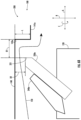
- FIG. 2 a perspective, cross-sectional view of a component assembly 100 of a rotary machine, such as turbofan engine 10 ( FIG. 1 ), is shown, according to one example embodiment. Even though the component assembly 100 will be frequently described in relation to the turbofan engine 10 , it should be understood that the present invention is applicable to other rotary machines, such as a steam turbine.
- the component assembly 100 of the rotary machine can include a rotor 120 and a stator 140 .
- the rotor 120 can define an axial direction A, a circumferential direction C, and a radial direction R.
- the radial direction R being perpendicular to the axial direction A, and the circumferential direction C being defined around the axial direction A.
- the rotor 120 can be configured so that it is rotatable about the axial direction A.
- the stator 140 can extend at least partially in the circumferential direction C and at least partially around the rotor 120 .
- the stator 140 can be configured so that it is not rotatable so that it remains stationary, in relation to other components of the rotary machine upon which it is installed.
- the rotor 120 is coupled to, and rotatable with, the LP shaft or spool 36 of the turbofan engine 10 ( FIG. 1 ).
- the rotor 120 is coupled to, and rotatable with, the HP shaft or spool 34 of the turbofan engine 10 ( FIG. 1 ).
- the stator 140 can be coupled to, either directly or indirectly, other non-rotating components, such as a casing 160 that can surround, at least partially, the stator 140 .
- the component assembly 100 of the rotary machine can include a seal 200 .
- the seal 200 can be coupled to the rotor 120 and positioned between the stator 140 and the rotor 120 .
- the seal 200 can extend circumferentially around the rotor 120 , either partially or fully.
- the seal 200 can be provided to prevent fluid leakage between the stator 140 and the rotor 120 by creating a curtain effect.
- the seal 200 can be provided to prevent a hot gas from flowing from a location that is forward of the component assembly 100 (left side of the page) to a location that is aft of the component assembly 100 (right side of the page). More particularly, the seal 200 may prevent the hot gas from flowing from a position forward of the seal 200 to a position aft of the seal 200 .
- the seal 200 extends from a circumferentially extending surface 122 of the rotor 120 of the component assembly 100 .
- the seal 200 includes a first flexible element 220 a .
- the first flexible element 220 a can be an assembly of a plurality of first flexible elements 220 a that extend partially around the rotor 120 , but can be assembled together, in close proximity, to extend fully around the rotor 120 . In other examples, the first flexible element 220 a is not an assembly and can extend fully around the rotor 120 .
- the thickness of the first flexible element 220 a along the axial direction A can be from 0.5 millimeter (mm) to five mm.
- the first flexible element 220 a can include a plurality of brush bristles (shown schematically as a single cross-section for clarity).
- Each brush bristle of the plurality of brush bristles can be substantially cylindrical shaped, with a diameter of less than 0.5 mm, such as between 0.15 and 0.25 mm.
- the diameter of each brush bristle may vary in relation to other brush bristles in the plurality of brush bristles. For example, smaller diameter brush bristles can be located within the axial center of the plurality of brush bristles, as compared to the brush bristles that are located at the forward and aft axial positions.
- the brush bristles can be manufactured from a metal.
- the brush bristles can be manufactured from a nickel alloy, a cobalt alloy, or a stainless steel.
- the brush bristles can be coupled to the rotor 120 by welding or with a mechanical fastener.
- the first flexible element 220 a can include a plurality of circumferentially-spaced flexible fingers. In yet other examples, the first flexible element 220 a can include at least one circumferentially-extending thin plate. In some embodiments, the at least one thin plate is a plurality of thin plates. Further, in some embodiments, at least one of the thin plates circumferentially overlaps another of the thin plates. In still other alternative embodiments, the first flexible element 220 a includes any suitably flexible structure that enables the seal 200 to function as described herein.
- the seal 200 can include a first backing plate 240 a .
- the first backing plate 240 a can be coupled to the rotor 120 and positioned adjacent to the first flexible element 220 a .
- the first backing plate 240 a can extend circumferentially around the rotor 120 , either partially or fully.
- the first backing plate 240 a is positioned forward of the first flexible element 220 a .
- the first backing plate 240 a is positioned aft of the first flexible element 220 a .
- the first backing plate 240 a can be provided to prevent the first flexible element 220 a from being damaged and/or plastically deformed when it experiences a centrifugal load when the rotor 120 is rotating.
- the first backing plate 240 a can at least partially support, i.e., bear a partial load of the first flexible element 220 a . More particularly, the first backing plate 240 a can be bent such that it deviates from the radial direction R.
- the first backing plate 240 a can have an aft surface that extends in a first direction 222 a , which forms a first angle 223 a between the radial direction R and the first direction 222 a , the first angle 223 a being forty five degrees or less, such as thirty five degrees or less, such as fifteen degrees or less.
- the first flexible element 220 a can be bent such that it deviates from the radial direction R.
- first flexible element 220 a can also extend in the first direction 222 a and can be pressed against the first backing plate 240 a . Even though shown as extending toward the aft side of the component assembly 100 , it should be understood that the first flexible element 220 a and the first backing plate 240 a can extend toward the forward side of the component assembly 100 .
- the seal 200 which can include the first backing plate 240 a and/or the first flexible element 220 a , can be configured the same as, or similarly to, the seal 100 , which can include the retaining plate 106 and/or the flexible element 110 , of U.S. application Ser. No. 14/869,538 filed Sep. 29, 2015, which is hereby incorporated by reference in its entirety.
- the seal 200 which can include the first backing plate 240 a and/or the first flexible element 220 a
- the seal 100 which can include the retaining plate 122 and/or the flexible element 124 , of U.S. application Ser. No. 15/248,161 filed Aug. 26, 2016, which is hereby incorporated by reference in its entirety.
- the seal 200 includes the first flexible element 220 a , a second flexible element 220 b , and a third flexible element 220 c .
- the first flexible element 220 a , the second flexible element 220 b , and the third flexible element 220 c can be configured the same as, or similarly to, the first flexible element 220 a as described in reference to FIG. 3 .
- the seal 200 can also include a backing plate for each of the first flexible element 220 a , the second flexible element 220 b , and the third flexible element 220 c , which can each be configured the same as, or similarly to, the first backing plate 240 a as described in reference to FIG. 3 .
- the first flexible element 220 a , the second flexible element 220 b , and the third flexible element 220 c can each be coupled to the rotor 120 and can each extend circumferentially, partially or fully, around the axial direction A.
- the first flexible element 220 a can extend in the first direction 222 a , which forms the first angle 223 a between the radial direction R and the first direction 222 a , the first angle 223 a being forty five degrees or less, such as thirty five degrees or less, such as fifteen degrees or less.
- the first flexible element 220 a extends towards the forward direction (left side of page), but in other examples, can extend in the aft direction (right side of page).
- the second flexible element 220 b can extend in a second direction 222 b and the third flexible element 220 c can extend in a third direction 222 c .
- the second direction 222 b and the third direction 222 c are the same as the axial direction; however, the second direction 222 b and/or the third direction 222 c could deviate from the axial direction A.
- the second direction 222 b could deviate from the axial direction A so that a second angle 223 b (see FIG. 5 ) is formed between the axial direction A and the second direction 222 b , the second angle 223 b being forty five degrees or less, such as thirty five degrees or less, such as fifteen degrees or less.
- the third direction 222 c could deviate from the axial direction A so that a third angle 223 c (see FIG. 5 ) is formed between the axial direction A and the third direction 222 c , the third angle 223 c being forty five degrees or less, such as thirty five degrees or less, such as fifteen degrees or less.
- the second flexible element 220 b extends in the forward direction and the third flexible element 220 c extends in the aft direction.
- the second angle 223 b or the third angle 223 c can be negative or positive such that the second direction 222 b or the third direction 222 c can be in the inward direction.
- the first flexible element 220 a can be provided to form a radial interface with the stator 140 to prevent a fluid from leaking between the rotor 120 and the stator 140 .
- the second flexible element 220 b and/or the third flexible element 220 c can be provided to form an axial interface with the stator 140 to prevent the fluid from leaking between the rotor 120 and the stator 140 .
- the first flexible element 220 a , the second flexible element 220 b , and/or the third flexible element 220 c can be provided to form both an axial interface and a radial interface with the stator 140 to prevent the fluid from leaking between the rotor 120 and the stator.
- the seal 200 includes a first flexible element 220 a , a first backing plate 240 a , a second flexible element 220 b , and a second backing plate 240 b .
- the seal 200 does not include the first backing plate 240 a and/or the second backing plate 240 b .
- the first flexible element 220 a , the first backing plate 240 a , the second flexible element 220 b , and the second backing plate 240 b can be configured similarly, or the same as, the examples provided in reference to FIG. 3 and FIG. 4 .
- the stator 140 includes a first protrusion 141 a that extends radially inward from the stator 140 and toward the rotor 120 .
- first protrusion 141 a has a rectangular cross-section in this example, it should be understood that the first protrusion 141 a can have any shape.
- the first protrusion 141 a extends radially inward from an axially and circumferentially extending surface 142 of the stator 140 , in this example.
- the first protrusion 141 a defines a first notch 143 a and a second notch 143 b .
- the first notch 143 a and the second notch 143 b are each defined where a root end 144 of the first protrusion 141 a and the axially and circumferentially extending surface 142 of the stator 140 join. More specifically, the first notch 143 a and the second notch 143 b are each defined at the locations where the axially and circumferentially extending surface 142 of the stator 140 meets with the radially extending surfaces 145 of the first protrusion 141 a . Even though shown as a sharp corner, it should be understood that the first notch 143 a and the second notch 143 b can be a fillet, a chamfer, or any other shape. Also, in this example, the first protrusion 141 a is located between the first flexible element 220 a and the second flexible element 220 b.
- the first backing plate 240 a , the first flexible element 220 a , the second backing plate 240 b , and the second flexible element 220 b each extend toward the first protrusion 141 a .
- the first flexible element 220 a and the first backing plate 240 a each extend in the first direction 222 a , the first direction 222 a being toward an aft direction when the first protrusion 141 a is aft of the first flexible element 220 a and the first backing plate 240 a ;
- the second flexible element 220 b and the second backing plate 240 b each extend in the second direction 222 b , the second direction 222 b being toward a forward direction when the first protrusion 141 a is forward of the second flexible element 220 b and the second backing plate 240 b.
- the first flexible element 220 a and the second flexible element 220 b can each have a tip 221 , which is an extremity of the respective flexible element 220 a , 220 b .
- the tip 221 can be shaped to conform to the shape of the respective notch 143 a or 143 b of the first protrusion 141 a .
- the tips 221 have a sharp angled tip to conform to the sharp corner of notches 143 a , 143 b of the first protrusion 141 a .
- the tips 221 of the first flexible element 220 a and the second flexible element 220 b can each have a bullnose or demi-bullnose shape so that they are also rounded.
- the tips 221 of the first flexible element 220 a and the second flexible element 220 b can also include a beveled edge to conform to the shape of the beveled corner.
- the seal 200 can be configured so that the tip 221 of one of the first flexible element 220 a or the second flexible element 220 b is configured to be positioned proximate to its respective notch 143 a , 143 b when the component assembly 100 is operating in a relatively hot state, and configured so that the tip 221 of the other one of the first flexible element 220 a or the second flexible element 220 b is configured to be positioned proximate to its respective notch 143 a , 143 b when the component assembly 100 is operating in a relatively cool state.
- a first distance D 1 from the tip 221 of the first flexible element 220 a to the first protrusion 141 a could be zero so that it is touching, or in close proximity, such as within three mm, such as within two mm, such as within one mm of the first notch 143 a when the component assembly 100 is operating in a relatively hot state, whereas a second distance D 2 from the tip 221 of the second flexible element 220 b to the first protrusion 141 a could be greater than first distance D 1 .
- the second distance D 2 could be at least one mm and up to ten mm, such as at least two mm and up to ten mm, such as at least three mm and up to ten mm, when the component assembly 100 is operating in a relatively hot state.
- the second distance D 2 from the tip 221 of the second flexible element 220 b to the first protrusion 141 a could be zero so that it is touching, or in close proximity, such as within three mm, such as within two mm, such as within one mm of the second notch 143 b when the component assembly 100 is operating in a relatively cool state, whereas the first distance D 1 from the tip 221 of the first flexible element 220 a to the first protrusion 141 a could be greater than second distance D 2 .
- the first distance D 1 could be at least one mm and up to ten mm, such as at least two mm and up to ten mm, such as at least three mm and up to ten mm, when the component assembly 100 is operating in a relatively cool state.
- FIG. 6 a and FIG. 6 b a schematic, cross-sectional view of a component assembly 100 with a seal 200 is depicted, according to an example embodiment. More particularly, FIG. 6 a depicts the component assembly 100 when the rotary machine is operating in a relatively hot state, whereas FIG. 6 b depicts the component assembly 100 when the rotary machine is operating in a relatively cool state.
- the seal 200 of FIG. 6 a and FIG. 6 b can be configured the same as, or similarly as, the seal 200 of FIG. 5 ; however, in this example, the seal 200 only includes the first backing plate 240 a and the first flexible element 220 a .
- the seal 200 includes more than the singular first backing plate 240 a and the first flexible element 220 a .
- the first flexible element 220 a of the seal 200 is positioned proximate the first notch 143 a defined by the first protrusion 141 a to prevent a fluid, such as a hot gas, from flowing from a position forward of the seal 200 to a position aft of the seal 200 .
- a fluid such as a hot gas
- the rotor 120 and the stator 140 may have different coefficients of thermal expansion and may move either axially and/or radially in relation to each other.
- the seal 200 can be configured so that the tip 221 of the first flexible element 220 a is configured to be positioned proximate to its respective first notch 143 a when the component assembly 100 is operating in a relatively hot state, and configured so that the tip 221 of the first flexible element 220 a is configured to be positioned further away from its respective first notch 143 a when the component assembly 100 is operating in a relatively cool state.
- a first distance D 1 along the axial direction A from the tip 221 of the first flexible element 220 a to the first protrusion 141 a could be zero so that it is touching, or in close proximity, such as within three mm, such as within two mm, such as within one mm of the first notch 143 a when the component assembly 100 is operating in a relatively hot state
- a second distance D 2 along the radial direction R from the tip 221 of the first flexible element 220 a to the stator 140 could be zero so that it is touching, or in close proximity, such as within three mm, such as within two mm, such as within one mm of the stator 140 when the component assembly 100 is operating in a relatively hot state.
- the first distance D 1 may be greater when the component assembly 100 is operating in a relatively cool state ( FIG. 6 b ) than when the component assembly 100 is operating in a relatively hot state ( FIG. 6 a ).
- the second distance D 2 may be greater when the component assembly 100 is operating in a relatively cool state ( FIG. 6 b ) than when the component assembly 100 is operating in a relatively hot state ( FIG. 6 a ).
- the first distance D 1 and/or the second distance D 2 could be at least one mm and up to ten mm, such as at least two mm and up to ten mm, such as at least three mm and up to ten mm, when the component assembly 100 is operating in a relatively cool state.
- the first flexible element 220 a can form both an axial interface and a radial interface with the stator 140 to prevent the fluid from leaking between the rotor 120 and the stator 140 . More particularly, the tip 221 of the first flexible element 220 a can form the axial interface with the radially extending surface 145 of the first protrusion 141 a of the stator 140 and the tip 221 of the first flexible element 220 a can form the radial interface with the circumferentially extending surface 142 of the stator 140 . As used herein, “interface” does not necessarily mean that contact must occur.
- an interface can occur with contact of the first flexible element 220 a with the stator 140 or when the first flexible element 220 a is in close proximity with the stator 140 .
- the axial and radial interface between the first flexible element 220 a and the stator 140 can prevent the fluid from leaking between the first flexible element 220 a and the stator 140 .
- the first notch should be sized to accommodate for the differing first distance D 1 and the second distance D 2 when the component assembly is operating in a relatively cool state versus when the component assembly 100 is operating in a relatively hot state.
- the first protrusion 141 a should have a radial length L that is greater than the second distance D 2 when the component assembly 100 is operating in a relatively cool state ( FIG. 6 b ).
- FIG. 7 a schematic, cross-sectional view of a component assembly 100 with a seal 200 is depicted, according to an example embodiment.
- the seal 200 of FIG. 7 can be configured the same as, or similarly as, the seal 200 of FIG. 5 ; however, in this example, the first flexible element 220 a extends in a first direction 222 a that is toward a forward side of the seal 200 (left side of page) and the second flexible element 220 b extends in a second direction 222 b that is toward an aft side of the seal 200 (right side of page).
- neither the first flexible element 220 a nor the second flexible element 220 b extend toward a notch that is defined by a protrusion that is positioned axially between the first flexible element 220 a and the second flexible element 220 b , such as third protrusion 141 c .
- the first flexible element 220 a extends toward a first notch 143 a that is defined by a first protrusion 141 a that is positioned axially forward of the first flexible element 220 a and the second flexible element 220 b extends toward a second notch 143 b that is defined by a second protrusion 141 b that is positioned axially aft of the second flexible element 220 b.
- the seal 200 can include a first backing plate 240 a that is located between the first flexible element 220 a and the second flexible element 220 b .
- first backing plate 240 a in this example is a unitary component that provides support for both the first flexible element 220 a and the second flexible element 220 b
- the seal 200 can include two separate backing plates that each support a different one of the first flexible element 220 a and the second flexible element 220 b.
- a first distance D 1 from the tip 221 of the first flexible element 220 a to the first protrusion 141 a could be zero so that it is touching, or in close proximity, such as within three mm, such as within two mm, such as within one mm of the first notch 143 a when the component assembly 100 is operating in a relatively cool state, whereas a second distance D 2 from the tip 221 of the second flexible element 220 b to the second protrusion 141 b could be greater than the first distance D 1 .
- the second distance D 2 could be at least one mm and up to ten mm, such as at least two mm and up to ten mm, such as at least three mm and up to ten mm, when the component assembly 100 is operating in a relatively cool state.
- the second distance D 2 from the tip 221 of the second flexible element 220 b to the second protrusion 141 b could be zero so that it is touching, or in close proximity, such as within three mm, such as within two mm, such as within one mm of the second notch 143 b when the component assembly 100 is operating in a relatively hot state, whereas the first distance D 1 from the tip 221 of the first flexible element 220 a to the first protrusion 141 a could be greater than second distance D 2 .
- the first distance D 1 could be at least one mm and up to ten mm, such as at least two mm and up to ten mm, such as at least three mm and up to ten mm, when the component assembly 100 is operating in a relatively hot state.
- the seal 200 can be configured so that the tip 221 of the first flexible element 220 a and the second flexible element 220 b are configured to be positioned approximately equidistant to their respective notches 143 a , 143 b when the component assembly 100 is operating at a median temperature, the median temperature being between the relatively hot state and the relatively cool state.
- the relatively hot state can be the hottest temperature experienced by the component assembly 100 when the component assembly 100 is operating normally
- the relatively cool state can be the coolest temperature experienced by the component assembly 100 when the component assembly 100 is operating normally.
- the relatively hot state could be experienced when an aircraft upon which the gas turbine engine is installed is taking-off, whereas the relatively cool state could be experienced when the gas turbine engine is initially turned on and on the ground.
- the stator 140 in this example, also includes the third protrusion 141 c that is positioned axially between the first flexible element 220 a and the second flexible element 220 b .
- the third protrusion 141 c that is positioned axially between the first flexible element 220 a and the second flexible element 220 b can partially define the tortuous path 150 .
- the rate of thermal expansion between the stator 140 and the rotor 120 can differ. As such, the rotor 120 may move closer to the stator 140 when the component assembly 100 is operating in a relatively hot state and the rotor 120 may move further from the stator 140 when the component assembly 100 is operating in a relatively cool state.
- a third distance D 3 between the third protrusion 141 c and the first backing plate 240 a , or between the third protrusion 141 c and the rotor 120 when the first backing plate 240 a is not positioned radially between the third protrusion 141 c and the first backing plate 240 a , can be minimized when the component assembly 100 is operating in a relatively hot state.
- the third distance D 3 could be less than ten mm, such as less than five mm, such as less than four mm when the component assembly 100 is operating in a relatively hot state.
- Minimizing the third distance D 3 when the component assembly 100 is operating in a relatively hot state can further decrease the amount of fluid, such as a hot gas, that is able to traverse through the seal 200 by increasing the number of curves and the slope of the curves on the tortuous path 150 .
- a seal for a rotor for preventing a gas from flowing from a position forward of the seal to a position aft of the seal, the rotor defining an axial direction, a circumferential direction, and a radial direction, the seal comprising: a first flexible element coupled to the rotor and extending in a first direction that is within forty five degrees of the axial direction; and a second flexible element coupled to the rotor and extending in a second direction that is within forty five degrees of the axial direction or within forty five degrees of the radial direction.
- first flexible element comprises a first plurality of brush bristles and the second flexible element comprises a second plurality of brush bristles.
- the seal of one or more of these clauses, wherein the second direction is within forty five degrees of the radial direction and the seal comprises a third flexible element coupled to the rotor and extending in a third direction that is within forty five degrees of the axial direction, wherein the first flexible element extends in a forward direction and the third flexible element extends in an aft direction.
- a rotary machine comprising: a rotor defining an axial direction, a circumferential direction, and a radial direction; a stator that extends at least partially in the circumferential direction and at least partially around the rotor; and a seal coupled to the rotor and positioned between the stator and the rotor, the seal comprising: a first flexible element coupled to the rotor and extending in a first direction that is within forty five degrees of the axial direction; and a second flexible element coupled to the rotor and extending in a second direction that is within forty five degrees of the axial direction or within forty five degrees of the radial direction.
- first flexible element comprises a first plurality of brush bristles and the second flexible element comprises a second plurality of brush bristles.
- the seal comprises a third flexible element coupled to the rotor and extending in a third direction that is within forty five degrees of the axial direction, wherein the first flexible element extends in a forward direction and the third flexible element extends in an aft direction.
- a rotary machine comprising: a rotor defining an axial direction, a circumferential direction, and a radial direction; a stator that extends at least partially in the circumferential direction and at least partially around the rotor, the stator comprising a first protrusion that defines a first notch; and a seal coupled to the rotor and positioned between the stator and the rotor, the seal comprising: a first flexible element having a first tip, wherein the first tip is positioned in close proximity to the first notch.
- the rotary machine is a gas turbine engine having a compressor section, a combustion section, a turbine section, and a shaft that couples the compressor section to the turbine section, wherein the rotor is coupled to, and rotatable with, the shaft.
- stator has an axially and circumferentially extending surface and the first protrusion has a radially extending surface, wherein the first notch is defined at a location where the axially and circumferentially extending surface of the stator meets with the radially extending surface of the first protrusion.
- a first distance is defined between the first tip of the first flexible element and the first notch, wherein the first distance is greater than or equal to zero millimeter (mm) and less than or equal to three mm.
- the first distance is greater than or equal to zero mm and less than or equal to three mm when the rotary machine is operating in a relatively hot state
- the first protrusion defines a second notch
- the seal comprises: a second flexible element having a second tip, wherein a second distance is defined between the second tip of the second flexible element and the second notch, wherein the second distance is greater than or equal to zero mm and less than or equal to three mm when the rotary machine is operating in a relatively cool state, wherein the first distance is less than the second distance when the rotary machine is operating in the relatively hot state and the first distance is greater than the second distance when the rotary machine is operating in the relatively cool state.
- the stator comprises a second protrusion that defines a second notch
- the seal comprises: a second flexible element having a second tip, wherein a second distance is defined between the second tip of the second flexible element and the second notch, wherein the second distance is greater than or equal to zero mm and less than or equal to three mm when the rotary machine is operating in a relatively hot state, wherein the first distance is less than the second distance when the rotary machine is operating in the relatively cool state and the first distance is greater than the second distance when the rotary machine is operating in the relatively hot state.
- stator comprises a third protrusion that is positioned axially between the first flexible element and the second flexible element.
- the first distance is greater than or equal to zero mm and less than or equal to three mm when the rotary machine is operating in a relatively hot state, and the first tip of the first flexible element is further away from the first notch when the rotary machine is operating in a relatively cool state, wherein the first distance is an axial distance.
Landscapes
- Engineering & Computer Science (AREA)
- Mechanical Engineering (AREA)
- General Engineering & Computer Science (AREA)
- Chemical & Material Sciences (AREA)
- Combustion & Propulsion (AREA)
- Turbine Rotor Nozzle Sealing (AREA)
- Structures Of Non-Positive Displacement Pumps (AREA)
Abstract
Description
Claims (12)
Priority Applications (2)
| Application Number | Priority Date | Filing Date | Title |
|---|---|---|---|
| US17/676,929 US12000296B2 (en) | 2022-02-22 | 2022-02-22 | Seal for a rotor |
| CN202310121869.0A CN116641762A (en) | 2022-02-22 | 2023-02-16 | Seal for a rotor |
Applications Claiming Priority (1)
| Application Number | Priority Date | Filing Date | Title |
|---|---|---|---|
| US17/676,929 US12000296B2 (en) | 2022-02-22 | 2022-02-22 | Seal for a rotor |
Publications (2)
| Publication Number | Publication Date |
|---|---|
| US20230265767A1 US20230265767A1 (en) | 2023-08-24 |
| US12000296B2 true US12000296B2 (en) | 2024-06-04 |
Family
ID=87573829
Family Applications (1)
| Application Number | Title | Priority Date | Filing Date |
|---|---|---|---|
| US17/676,929 Active US12000296B2 (en) | 2022-02-22 | 2022-02-22 | Seal for a rotor |
Country Status (2)
| Country | Link |
|---|---|
| US (1) | US12000296B2 (en) |
| CN (1) | CN116641762A (en) |
Citations (13)
| Publication number | Priority date | Publication date | Assignee | Title |
|---|---|---|---|---|
| US4645424A (en) | 1984-07-23 | 1987-02-24 | United Technologies Corporation | Rotating seal for gas turbine engine |
| US5498139A (en) | 1994-11-09 | 1996-03-12 | United Technologies Corporation | Brush seal |
| US5630590A (en) | 1996-03-26 | 1997-05-20 | United Technologies Corporation | Method and apparatus for improving the airsealing effectiveness in a turbine engine |
| US9255486B2 (en) * | 2011-03-28 | 2016-02-09 | General Electric Company | Rotating brush seal |
| US9863538B2 (en) | 2015-04-27 | 2018-01-09 | United Technologies Corporation | Gas turbine engine brush seal with supported tip |
| US9963992B2 (en) | 2015-09-29 | 2018-05-08 | General Electric Company | Centrifugally activatable seal for a rotary machine and method of assembling same |
| US10208674B2 (en) * | 2013-03-13 | 2019-02-19 | United Technologies Corporation | Multi-axial brush seal |
| US10400896B2 (en) * | 2014-08-28 | 2019-09-03 | United Technologies Corporation | Dual-ended brush seal assembly and method of manufacture |
| US10519793B2 (en) * | 2017-03-31 | 2019-12-31 | Safran Aero Boosters Sa | Brush seal for a turbine engine rotor |
| US10533567B2 (en) * | 2017-05-30 | 2020-01-14 | United Technologies Corporation | Deflection spring seal |
| US10683769B2 (en) | 2016-08-26 | 2020-06-16 | General Electric Company | Centrifugally activatable seal for a rotary machine and method of assembling same |
| US10837303B2 (en) * | 2017-09-27 | 2020-11-17 | DOOSAN Heavy Industries Construction Co., LTD | Tip sealing structure for blade, rotor including same, and gas turbine including same |
| US10844741B2 (en) | 2016-11-21 | 2020-11-24 | Pratt & Whitney Canada Corp. | Brush seal assembly and method |
-
2022
- 2022-02-22 US US17/676,929 patent/US12000296B2/en active Active
-
2023
- 2023-02-16 CN CN202310121869.0A patent/CN116641762A/en active Pending
Patent Citations (13)
| Publication number | Priority date | Publication date | Assignee | Title |
|---|---|---|---|---|
| US4645424A (en) | 1984-07-23 | 1987-02-24 | United Technologies Corporation | Rotating seal for gas turbine engine |
| US5498139A (en) | 1994-11-09 | 1996-03-12 | United Technologies Corporation | Brush seal |
| US5630590A (en) | 1996-03-26 | 1997-05-20 | United Technologies Corporation | Method and apparatus for improving the airsealing effectiveness in a turbine engine |
| US9255486B2 (en) * | 2011-03-28 | 2016-02-09 | General Electric Company | Rotating brush seal |
| US10208674B2 (en) * | 2013-03-13 | 2019-02-19 | United Technologies Corporation | Multi-axial brush seal |
| US10400896B2 (en) * | 2014-08-28 | 2019-09-03 | United Technologies Corporation | Dual-ended brush seal assembly and method of manufacture |
| US9863538B2 (en) | 2015-04-27 | 2018-01-09 | United Technologies Corporation | Gas turbine engine brush seal with supported tip |
| US9963992B2 (en) | 2015-09-29 | 2018-05-08 | General Electric Company | Centrifugally activatable seal for a rotary machine and method of assembling same |
| US10683769B2 (en) | 2016-08-26 | 2020-06-16 | General Electric Company | Centrifugally activatable seal for a rotary machine and method of assembling same |
| US10844741B2 (en) | 2016-11-21 | 2020-11-24 | Pratt & Whitney Canada Corp. | Brush seal assembly and method |
| US10519793B2 (en) * | 2017-03-31 | 2019-12-31 | Safran Aero Boosters Sa | Brush seal for a turbine engine rotor |
| US10533567B2 (en) * | 2017-05-30 | 2020-01-14 | United Technologies Corporation | Deflection spring seal |
| US10837303B2 (en) * | 2017-09-27 | 2020-11-17 | DOOSAN Heavy Industries Construction Co., LTD | Tip sealing structure for blade, rotor including same, and gas turbine including same |
Also Published As
| Publication number | Publication date |
|---|---|
| US20230265767A1 (en) | 2023-08-24 |
| CN116641762A (en) | 2023-08-25 |
Similar Documents
| Publication | Publication Date | Title |
|---|---|---|
| EP3734018B1 (en) | Seal for a gas turbine engine component and corresponding method | |
| US10227879B2 (en) | Centrifugal compressor assembly for use in a turbine engine and method of assembly | |
| EP3064711A1 (en) | Component, corresponding gas turbine engine and method | |
| EP3093445B1 (en) | Gas turbine vane and method of forming | |
| EP3450680B1 (en) | Turbine rotor disk | |
| EP3450690B1 (en) | Turbine rotor | |
| US10954953B2 (en) | Rotor hub seal | |
| EP3056685B1 (en) | Stator vane with platform having sloped face | |
| US11473434B2 (en) | Gas turbine engine airfoil | |
| EP3450685B1 (en) | Gas turbine engine component | |
| WO2020106719A2 (en) | Seal assembly for a turbo machine | |
| US12000296B2 (en) | Seal for a rotor | |
| US10815821B2 (en) | Variable airfoil with sealed flowpath | |
| US10787921B2 (en) | High pressure turbine rear side plate | |
| US10968762B2 (en) | Seal assembly for a turbo machine | |
| US12044172B2 (en) | Air guide for a gas turbine engine | |
| US11725531B2 (en) | Bore compartment seals for gas turbine engines | |
| US12247580B2 (en) | Forward load reduction structures for aft-most stages of high pressure compressors | |
| US20240418130A1 (en) | Gas turbine engine defining a rotor cavity | |
| US20240418096A1 (en) | Gas turbine engine defining a rotor cavity | |
| EP3789586B1 (en) | Aerodynamic element assembly for a gas turbine engine | |
| EP3056686B1 (en) | Rotor with axial arm having protruding ramp | |
| CN119145950A (en) | Gas turbine engine defining a rotor cavity |
Legal Events
| Date | Code | Title | Description |
|---|---|---|---|
| AS | Assignment |
Owner name: GENERAL ELECTRIC COMPANY, NEW YORK Free format text: ASSIGNMENT OF ASSIGNORS INTEREST;ASSIGNORS:JOHNSON, STEVEN DOUGLAS;SARAWATE, NEELESH NANDKUMAR;REEL/FRAME:059064/0505 Effective date: 20220204 |
|
| FEPP | Fee payment procedure |
Free format text: ENTITY STATUS SET TO UNDISCOUNTED (ORIGINAL EVENT CODE: BIG.); ENTITY STATUS OF PATENT OWNER: LARGE ENTITY |
|
| STPP | Information on status: patent application and granting procedure in general |
Free format text: FINAL REJECTION MAILED |
|
| STPP | Information on status: patent application and granting procedure in general |
Free format text: RESPONSE AFTER FINAL ACTION FORWARDED TO EXAMINER |
|
| STPP | Information on status: patent application and granting procedure in general |
Free format text: ADVISORY ACTION MAILED |
|
| STPP | Information on status: patent application and granting procedure in general |
Free format text: RESPONSE AFTER FINAL ACTION FORWARDED TO EXAMINER |
|
| STPP | Information on status: patent application and granting procedure in general |
Free format text: NOTICE OF ALLOWANCE MAILED -- APPLICATION RECEIVED IN OFFICE OF PUBLICATIONS |
|
| STPP | Information on status: patent application and granting procedure in general |
Free format text: PUBLICATIONS -- ISSUE FEE PAYMENT VERIFIED |
|
| STCF | Information on status: patent grant |
Free format text: PATENTED CASE |