US1198923A - Electrically-operated cutter. - Google Patents
Electrically-operated cutter. Download PDFInfo
- Publication number
- US1198923A US1198923A US79724513A US1913797245A US1198923A US 1198923 A US1198923 A US 1198923A US 79724513 A US79724513 A US 79724513A US 1913797245 A US1913797245 A US 1913797245A US 1198923 A US1198923 A US 1198923A
- Authority
- US
- United States
- Prior art keywords
- cutter
- electrically
- base
- contact
- conductor
- Prior art date
- Legal status (The legal status is an assumption and is not a legal conclusion. Google has not performed a legal analysis and makes no representation as to the accuracy of the status listed.)
- Expired - Lifetime
Links
Images
Classifications
-
- B—PERFORMING OPERATIONS; TRANSPORTING
- B26—HAND CUTTING TOOLS; CUTTING; SEVERING
- B26B—HAND-HELD CUTTING TOOLS NOT OTHERWISE PROVIDED FOR
- B26B15/00—Hand-held shears with motor-driven blades
Definitions
- My present invention relates 1n general to cutter devices, and more partlcularly mechanically operated devices for cutting sheets, and has special reference to the provision of an improved cutter of the reciprocating type.
- the principal objects of my present invention are the provision of an improved cutter of the class referred to, characterized by the employment of a simple form of electromagnetic operating means for imparting the reciprocatory motion to the cutter; the provision of an improved form of electrically operated cutter employing a simple form of controlling switch for the electro-magnetic operating means; the provision of an 1mproved form of cutting mechanism for outters; and generally to improve and cheapen the cost of cutters of the nature referred to, together with such other objects as may hereinafter appear.
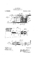
- FIG. 1 is a side elevational view. of a cutter embodying my present improvements
- Fig. 2 is a plan view thereof
- Fig. 3 is a sectional under-plan view taken on the line 33 of Fig. 1.
- Fig. 1 of the drawing it will be observed that I have here illustrated an embodiment of my improved cutter in the portable form designed for use by garment makers in the cutting of single thicknesses of cloth, though I obviously my present improvements are susceptible of a wide range of usefulness by a suitable modification in the sizes of the various parts.
- a base 10 which is preferably made of insulating material highly polished and shaped to slide easily on the cutting table, mounting upon said base a frame including members 12 within which are disposed a pair of magnet coils 14, 14, joined together in se- Specification of Letters Patent.
- the coils 1414 areprovided with the usual contact points 16, 16, against which the armature 17 is adapted to bear, such armature 17 being flexibly hinged to the frame member 12 by the strap of flexible spring metal indicated at 18, which strap acts as an interrupter and is continued to form a contact at 19 with the contact member employed in connection with the binding post 20.
- the hinge connection just referred to is, as will be seen on inspection of the drawings, transverse to the cutting edges of the knives shortly to be described.
- a stationary knife 21 having an inclined and chamfered cutting edge as indicated at 22 and disposed opposite to said lmife 21 is a knife 23 having an oppositely inclined and chamfered cutting edge 24.
- the knife 23 is preferably disposed in a guide slot indicated at 25 (Fig. 3) in a lateral extension 26 of a supporting member 27 which is attached to the frame 12 as indicated at 28, the shank'29 of said knife 23 being pivoted at 30 to an extension 31 of the armature 17.
- a handle 32 is employed for moving the device about, and at 33 is indicated a contact button having an insulated covering.
- the contact button 33 is carried on a spring strip 34 which is connected by a conductor 38 from one of the coils 14, the conductor 39 of the other coil 14 being fed from a suit able source of electric current supply (not shown), and the opposite pole of said source of supply being connected by a conductor 40 to a contact point 43 on the strip 18, a conductor 44 being used to connect the binding post 20 and the contact post 41 (Fig. 2) opposite said contact 33 and insulated therefrom.
- the handle 32 is grasped and the cutter moved to the desired position relatively to the sheet of material to be cut, indicated diagrammatically at 42, and the button 33 pressed into contact with the point 41, thereby completing the circuit between the conductors 39 and 40 and exciting the magnet coils 14, 14, which in turn vibrate the armature 17, carrying the extension 31 to which the knife shank 29 is pivoted, thus causing rapid reciprocation of the blade 23 relatively to the blade 21.
- a cutter device of the character described comprising, in combination, a base, a cutter member on said base adjacent one side of said base, means for operating said cutter adjacent the other side of said base,
- a cutter device of the character described comprising, in combination, a base, a pair of oppositely disposed cutter mem bers in operative relation, mounted on said base, adjacent one end thereof, means for producing reciprocatory movement of one of said cutters, relatively to the other adjacent the other end of said base, and a handle of greater length than Width or height, mounted on said base, substantially parallel thereto, With its mid-point substantially vertically over the point of engagement of said cutters With the other.
Landscapes
- Life Sciences & Earth Sciences (AREA)
- Forests & Forestry (AREA)
- Engineering & Computer Science (AREA)
- Mechanical Engineering (AREA)
- Knives (AREA)
Description
E. G. JOHANSON.
ELECTRICALLY OPERATED CUTTER. APPLICATION FILED OCT. 25. 1913.
1 1 98, 92 3 Patented Sept. 19, 1916.
5% J8 4 3 52 J9 2% 745 J j 30 26 J EMIL GOTTFRIED J OHANSON, OF ROCKFORD, ILLINOIS.
ELECTRICALLY-OPERATED CUTTER.
Application filed October 25,
T 0 all whom it may concern Be it known that I, EMIL GOTTFRIED J o- HANSON; a citizen of the United States, and resident of Rockford, in the county of VVlnnebago and State of Illinois, have invented certain new and useful Improvement-s 1n Electrically-Operated Cutters, of which the following is a specification.
My present invention relates 1n general to cutter devices, and more partlcularly mechanically operated devices for cutting sheets, and has special reference to the provision of an improved cutter of the reciprocating type.
The principal objects of my present invention are the provision of an improved cutter of the class referred to, characterized by the employment of a simple form of electromagnetic operating means for imparting the reciprocatory motion to the cutter; the provision of an improved form of electrically operated cutter employing a simple form of controlling switch for the electro-magnetic operating means; the provision of an 1mproved form of cutting mechanism for outters; and generally to improve and cheapen the cost of cutters of the nature referred to, together with such other objects as may hereinafter appear.
In attaining the foregoing objects I have provided a construction, a preferred embodiment of which is illustrated in the accompanying drawing, wherein Figure 1 is a side elevational view. of a cutter embodying my present improvements; Fig. 2 is a plan view thereof; and Fig. 3 is a sectional under-plan view taken on the line 33 of Fig. 1.
Referring now more particularly to Fig. 1 of the drawing, it will be observed that I have here illustrated an embodiment of my improved cutter in the portable form designed for use by garment makers in the cutting of single thicknesses of cloth, though I obviously my present improvements are susceptible of a wide range of usefulness by a suitable modification in the sizes of the various parts.
In the construction shown in the drawing I employ a base 10 which is preferably made of insulating material highly polished and shaped to slide easily on the cutting table, mounting upon said base a frame including members 12 within which are disposed a pair of magnet coils 14, 14, joined together in se- Specification of Letters Patent.
Patented Sept. 19, 1916.
1913. Serial No. 797,245.
rice in the customary manner as indicated at 15. The coils 1414 areprovided with the usual contact points 16, 16, against which the armature 17 is adapted to bear, such armature 17 being flexibly hinged to the frame member 12 by the strap of flexible spring metal indicated at 18, which strap acts as an interrupter and is continued to form a contact at 19 with the contact member employed in connection with the binding post 20. The hinge connection just referred to is, as will be seen on inspection of the drawings, transverse to the cutting edges of the knives shortly to be described.
On the base 10 I mounta stationary knife 21 having an inclined and chamfered cutting edge as indicated at 22 and disposed opposite to said lmife 21 is a knife 23 having an oppositely inclined and chamfered cutting edge 24. The knife 23 is preferably disposed in a guide slot indicated at 25 (Fig. 3) in a lateral extension 26 of a supporting member 27 which is attached to the frame 12 as indicated at 28, the shank'29 of said knife 23 being pivoted at 30 to an extension 31 of the armature 17.
A handle 32 is employed for moving the device about, and at 33 is indicated a contact button having an insulated covering. The contact button 33 is carried on a spring strip 34 which is connected by a conductor 38 from one of the coils 14, the conductor 39 of the other coil 14 being fed from a suit able source of electric current supply (not shown), and the opposite pole of said source of supply being connected by a conductor 40 to a contact point 43 on the strip 18, a conductor 44 being used to connect the binding post 20 and the contact post 41 (Fig. 2) opposite said contact 33 and insulated therefrom.
In the operation of cutters embodying my present improvements, the handle 32 is grasped and the cutter moved to the desired position relatively to the sheet of material to be cut, indicated diagrammatically at 42, and the button 33 pressed into contact with the point 41, thereby completing the circuit between the conductors 39 and 40 and exciting the magnet coils 14, 14, which in turn vibrate the armature 17, carrying the extension 31 to which the knife shank 29 is pivoted, thus causing rapid reciprocation of the blade 23 relatively to the blade 21.
When the button 33 is depressed, the electric circuit is completed as follows, viz. conductor 40, point 43, interrupter spring 18, contact, 19, conductor, 4 1, spring 34, contact, 41, conductor, 38, through coils, 14.--14:, (which are connected by conductor, 15,) and conductor, 39, to a source of power, (not shoWn,) thus energizing the coils, 14 14:, and causing the armature, 17, to be attracted thereto, thereby opening the circuit at 19, and thus deenergizing said coils, 14-14=, Which permits the raising of the armature, 17 by means of the spring, 18, thereby restoring the circuit just described, When the operation is repeated.
Having thus described my invention and illustrated its use, What I claim as new and desire to secure by Letters Patent is:
1. A cutter device of the character described comprising, in combination, a base, a cutter member on said base adjacent one side of said base, means for operating said cutter adjacent the other side of said base,
and a handle substantially vertically over said cutter.
2. A cutter device of the character described, comprising, in combination, a base, a pair of oppositely disposed cutter mem bers in operative relation, mounted on said base, adjacent one end thereof, means for producing reciprocatory movement of one of said cutters, relatively to the other adjacent the other end of said base, and a handle of greater length than Width or height, mounted on said base, substantially parallel thereto, With its mid-point substantially vertically over the point of engagement of said cutters With the other.
In testimony whereof I have hereunto signed my name in the presence of the two subscribed Witnesses.
EMIL GOTTFRIED J OHANSON.
Witnesses MARTHA WESTMAN, PAUL CARPENTER.
Priority Applications (1)
| Application Number | Priority Date | Filing Date | Title |
|---|---|---|---|
| US79724513A US1198923A (en) | 1913-10-25 | 1913-10-25 | Electrically-operated cutter. |
Applications Claiming Priority (1)
| Application Number | Priority Date | Filing Date | Title |
|---|---|---|---|
| US79724513A US1198923A (en) | 1913-10-25 | 1913-10-25 | Electrically-operated cutter. |
Publications (1)
| Publication Number | Publication Date |
|---|---|
| US1198923A true US1198923A (en) | 1916-09-19 |
Family
ID=3266867
Family Applications (1)
| Application Number | Title | Priority Date | Filing Date |
|---|---|---|---|
| US79724513A Expired - Lifetime US1198923A (en) | 1913-10-25 | 1913-10-25 | Electrically-operated cutter. |
Country Status (1)
| Country | Link |
|---|---|
| US (1) | US1198923A (en) |
-
1913
- 1913-10-25 US US79724513A patent/US1198923A/en not_active Expired - Lifetime
Similar Documents
| Publication | Publication Date | Title |
|---|---|---|
| US6651538B2 (en) | Microtome | |
| US1421350A (en) | Hair-cutting machine | |
| US1198923A (en) | Electrically-operated cutter. | |
| US3745286A (en) | Trigger operated tool handle switch | |
| US3478426A (en) | Electric scissors | |
| US2320784A (en) | Seam ripper | |
| US2283551A (en) | Vibratory electric motor apparatus | |
| US2304525A (en) | Hair clipper | |
| US1680627A (en) | Electrically-operated scissors | |
| US2810030A (en) | Electric switches | |
| US2225580A (en) | Electric scissors | |
| US2283403A (en) | Electric scissors | |
| US2273536A (en) | Electrical shears | |
| US2502036A (en) | Electric shaver | |
| US1922824A (en) | Electric motor | |
| US2652563A (en) | Stapling device | |
| US1861043A (en) | Hair clipper | |
| US3601894A (en) | Portable electric shearing devices | |
| US1471536A (en) | Clipper | |
| US2085462A (en) | Scrollwork cutter | |
| US2337791A (en) | Electrical switch | |
| US432433A (en) | Animal-clipper | |
| GB675234A (en) | Improvements in or relating to dry shaving appliances | |
| US1122523A (en) | Electric paper-cutter. | |
| US2083405A (en) | Electric motor |