US11972619B2 - Information processing device, information processing system, information processing method and computer-readable recording medium - Google Patents
Information processing device, information processing system, information processing method and computer-readable recording medium Download PDFInfo
- Publication number
- US11972619B2 US11972619B2 US17/395,666 US202117395666A US11972619B2 US 11972619 B2 US11972619 B2 US 11972619B2 US 202117395666 A US202117395666 A US 202117395666A US 11972619 B2 US11972619 B2 US 11972619B2
- Authority
- US
- United States
- Prior art keywords
- display
- region
- image
- count value
- interest
- Prior art date
- Legal status (The legal status is an assumption and is not a legal conclusion. Google has not performed a legal analysis and makes no representation as to the accuracy of the status listed.)
- Active, expires
Links
Images


Classifications
-
- G—PHYSICS
- G06—COMPUTING OR CALCULATING; COUNTING
- G06V—IMAGE OR VIDEO RECOGNITION OR UNDERSTANDING
- G06V20/00—Scenes; Scene-specific elements
- G06V20/60—Type of objects
- G06V20/69—Microscopic objects, e.g. biological cells or cellular parts
-
- G—PHYSICS
- G02—OPTICS
- G02B—OPTICAL ELEMENTS, SYSTEMS OR APPARATUS
- G02B21/00—Microscopes
- G02B21/36—Microscopes arranged for photographic purposes or projection purposes or digital imaging or video purposes including associated control and data processing arrangements
- G02B21/365—Control or image processing arrangements for digital or video microscopes
- G02B21/367—Control or image processing arrangements for digital or video microscopes providing an output produced by processing a plurality of individual source images, e.g. image tiling, montage, composite images, depth sectioning, image comparison
-
- G—PHYSICS
- G02—OPTICS
- G02B—OPTICAL ELEMENTS, SYSTEMS OR APPARATUS
- G02B21/00—Microscopes
- G02B21/36—Microscopes arranged for photographic purposes or projection purposes or digital imaging or video purposes including associated control and data processing arrangements
- G02B21/368—Microscopes arranged for photographic purposes or projection purposes or digital imaging or video purposes including associated control and data processing arrangements details of associated display arrangements, e.g. mounting of LCD monitor
-
- G—PHYSICS
- G06—COMPUTING OR CALCULATING; COUNTING
- G06T—IMAGE DATA PROCESSING OR GENERATION, IN GENERAL
- G06T7/00—Image analysis
- G06T7/70—Determining position or orientation of objects or cameras
- G06T7/73—Determining position or orientation of objects or cameras using feature-based methods
-
- G—PHYSICS
- G06—COMPUTING OR CALCULATING; COUNTING
- G06V—IMAGE OR VIDEO RECOGNITION OR UNDERSTANDING
- G06V10/00—Arrangements for image or video recognition or understanding
- G06V10/20—Image preprocessing
- G06V10/25—Determination of region of interest [ROI] or a volume of interest [VOI]
-
- H—ELECTRICITY
- H04—ELECTRIC COMMUNICATION TECHNIQUE
- H04N—PICTORIAL COMMUNICATION, e.g. TELEVISION
- H04N7/00—Television systems
- H04N7/18—Closed-circuit television [CCTV] systems, i.e. systems in which the video signal is not broadcast
-
- G—PHYSICS
- G06—COMPUTING OR CALCULATING; COUNTING
- G06T—IMAGE DATA PROCESSING OR GENERATION, IN GENERAL
- G06T2207/00—Indexing scheme for image analysis or image enhancement
- G06T2207/10—Image acquisition modality
- G06T2207/10056—Microscopic image
-
- G—PHYSICS
- G06—COMPUTING OR CALCULATING; COUNTING
- G06T—IMAGE DATA PROCESSING OR GENERATION, IN GENERAL
- G06T2207/00—Indexing scheme for image analysis or image enhancement
- G06T2207/20—Special algorithmic details
- G06T2207/20212—Image combination
- G06T2207/20221—Image fusion; Image merging
-
- G—PHYSICS
- G06—COMPUTING OR CALCULATING; COUNTING
- G06T—IMAGE DATA PROCESSING OR GENERATION, IN GENERAL
- G06T2207/00—Indexing scheme for image analysis or image enhancement
- G06T2207/30—Subject of image; Context of image processing
- G06T2207/30242—Counting objects in image
Definitions
- the disclosure relates to an information processing device, an information processing system, an information processing method, and a computer-readable recording medium.
- a technique of enlarging part of a specimen image that is digitized by virtual slide and thus displaying the specimen image is known (For example, Japanese National Publication of International Patent Application No. 2015-504529).
- a digital specimen image larger than a field of view of a microscope can be displayed by combining and stitching multiple images and the user moves a positon of display of the specimen image to up, down, right and left and changes a display magnification by operating a zoom, thereby performing observation while searching the specimen image for a region of interest that is important in diagnosis.
- an information processing device includes: a storage configured to store display region information and a count value, the display region information indicating a position of a predetermined display region in the first image corresponding to the image data that is input from an external device, the count value indicating frequency of display of each predetermined region in the first image; and a processor including hardware, the processor being configured to, based on the image data and an instruction signal that is input from an external device to select the display region, generate a display image corresponding to the display region that is selected by the instruction signal, using the first image, determine whether the display region information meets a first condition, add a predetermined value to the count value of the region on which it is determined that the first condition is met, and set, for a region of interest, a region that draws an interest in the first image, based on the count value.
- an information processing system includes an observation device configured to observe a subject, a storage configured to store a position in which the subject is selected by the observation device, a field-of-view information indicating at least a size of a field of view of the observation device, and a count value indicating frequency of display of each predetermined region; and a processor comprising hardware, the processor being configured to determine whether the field-of-view information meets a predetermined condition, add a predetermined value to the count value of the region on which it is determined that the predetermined condition is met, and set, for a region of interest, a region that draws an interest in a coordinate system corresponding to the subject based on the count value.
- an information processing method that is executed by an information processing device. The method includes: based on the image data that is input from an external device and an instruction signal that is input from an external device to select a predetermined display region in an image corresponding to the image data, generating a display image corresponding to the display region that is selected by the instruction signal, using a first image corresponding to the image data; acquiring display region information from a storage configured to store the display region information indicating a position of the display region in the first image and a count value indicating frequency of display of each predetermined region in the first image; determining whether the display region information meets a predetermined condition; incrementally increasing the count value of the region on which it is determined that the predetermined condition is met; and setting, for a region of interest, a region that draws an interest in the first image based on the count value.
- a non-transitory computer-readable recording medium with an executable program stored thereon.
- the program causes an information processing device to: based on the image data that is input from an external device and an instruction signal that is input from an external device to select a predetermined display region in an image corresponding to the image data, generate a display image corresponding to the display region that is selected by the instruction signal, using a first image corresponding to the image data; acquire display region information from a storage configured to store the display region information indicating a position of the display region in the first image and a count value indicating frequency of display of each predetermined region in the first image; determine whether the display region information meets a predetermined condition; incrementally increase the count value of the region on which it is determined that the predetermined condition is met; and set, for a region of interest, a region that draws an interest in the first image based on the count value.
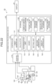
- FIG. 1 is a block diagram illustrating a functional configuration of an information processing system according to a first embodiment
- FIG. 2 is a flowchart illustrating an overview of a process that is executed by an information processing device
- FIG. 3 is a flowchart illustrating an overview of an addition process in FIG. 2 ;
- FIG. 4 is a diagram illustrating an example of a superimposed image that a display controller causes a display unit to display according to the first embodiment
- FIG. 5 is a flowchart illustrating an overview of an addition process according to Modification 2 of the first embodiment
- FIG. 6 is a diagram illustrating an example of a superimposed image that the display controller causes the display unit to display according to Modification 2 of the first embodiment
- FIG. 7 is a flowchart illustrating an overview of an addition process according to Modification 3 of the first embodiment
- FIG. 8 is a diagram illustrating an example of a superimposed image that the display controller causes the display unit to display according to Modification 3 of the first embodiment
- FIG. 9 is a flowchart illustrating an overview of an addition process according to Modification 4 of the first embodiment
- FIG. 10 is a diagram illustrating an example of a superimposed image that the display controller causes the display unit to display according to Modification 4 of the first embodiment
- FIG. 11 is a block diagram illustrating a functional configuration of an information processing system according to a second embodiment
- FIG. 12 is a diagram schematically illustrating an example of a first image that is acquired by an acquisition unit according to the second modification
- FIG. 13 is a diagram schematically illustrating an example of the first image on which segmentation has been performed
- FIG. 14 is a diagram schematically illustrating an example of a superimposed image
- FIG. 15 is a diagram schematically illustrating an example of a similar region
- FIG. 16 is a block diagram illustrating a functional configuration of an information processing system according to a third embodiment
- FIG. 17 is a schematic diagram illustrating a functional configuration of an information processing system according to a fourth embodiment.
- FIG. 18 is a diagram schematically illustrating a stage according to the forth embodiment
- FIG. 19 is a diagram schematically illustrating registers corresponding to the stage according to the forth embodiment.
- FIG. 20 is a diagram schematically illustrating an example of a superimposed image according to the fourth embodiment.
- FIG. 21 is a diagram schematically illustrating a position of a cover glass on a slide glass according to the fourth embodiment
- FIG. 22 is a schematic diagram illustrating a functional configuration of an information processing system according to Modification 1 of the fourth embodiment
- FIG. 23 is a schematic diagram illustrating a functional configuration of an information processing system according to Modification 2 of the fourth embodiment
- FIG. 24 is a schematic diagram illustrating a functional configuration of an information processing system according to Modification 3 of the fourth embodiment.
- FIG. 25 is a block diagram illustrating a functional configuration of an information processing system according to a fifth embodiment
- FIG. 26 is a diagram schematically illustrating an example of a CT image according to the fifth embodiment.
- FIG. 27 is a diagram schematically illustrating an addition method of adding a count value of frequency of display of each cross-sectional image according to the fifth embodiment.
- FIG. 28 is a diagram schematically illustrating that a region of interest is displayed in a superimposed manner stereoscopically on a CT image according to the fifth embodiment.
- FIG. 1 is a block diagram illustrating a functional configuration of an information processing system according to a first embodiment.
- the information processing system 1 illustrated in FIG. 1 includes an information processing device 10 , an image database 20 (“image DB 20 ” below), an operation unit 30 , and a display unit 40 .
- the information processing device 10 acquires desired image data from multiple sets of image data that are recorded in the image DB 20 according to an operation of the user on the operation unit 30 and outputs, to the display unit 40 , a display image that is based on the image data and that corresponds to a display region (observation field of view) corresponding to an instruction signal corresponding to an instruction on the operation unit 30 .
- the image data is two-dimensional plane data obtained by capturing an image of a specimen or a sample by a microscope, or the like. The detailed configuration of the information processing device 10 will be described below.
- the image DB 20 stores the sets of two-dimensional image data generated by capturing images of a specimen or a sample by a microscope, or the like.
- the image DB 20 consists of a server system connected via a network or a local hard disk drive (HDD) and a solid state drive (SSD), or the like.
- HDD hard disk drive
- SSD solid state drive
- the operation unit 30 receives an operation of the user and outputs an instruction signal corresponding to the received operation to the information processing device 10 .
- the operation unit 30 consists of a keyboard, a mouse, a touch panel, etc.
- the display unit 40 displays the image corresponding to the image data that is input from the information processing device 10 .
- the display unit 40 consists of a liquid crystal or organic electro luminescence (EL) display panel, or the like.
- the information processing device 10 includes an acquisition unit 11 , a storage 12 and a controller 13 .
- the acquisition unit 11 acquires image data that is selected according to an instruction signal that is input from the operation unit 30 from multiple sets of two-dimensional planes that are stored in the image DB 20 .
- the acquisition unit 11 consists of, for example, a predetermined I/F circuit.
- the acquisition unit 11 acquires image data from the image DB 20 in a wired or wireless manner.
- the storage 12 includes a display information storage 121 that stores display region information indicating the position of a predetermined display region in the image that is displayed on the display unit 40 and that is in a first image (subject image) corresponding to the image data that is acquired by the acquisition unit 11 ; a count value storage 122 that stores a count value (“count value” below) indicating frequency of display of each predetermined region in the display region in the subject image that is displayed on the display unit 40 ; and a program storage 123 that stores various programs to be executed by the information processing system 1 .
- the storage 12 consists of a volatile memory, a non-volatile memory, a HDD, a SSD, a memory card, etc.
- the controller 13 controls each of the units of which the information processing system 1 consists.
- the controller 13 consists of hardware including a memory and processors, such as a central processing unit (CPU), a field programmable gate array (FPGA) and an application specific integrated circuit (ASIC).
- the controller 13 includes a first generator 131 , a calculator 132 , a first determination unit 133 , an adder 134 , a setting unit 136 , a second generator 137 , and a display controller 138 .
- the first generator 131 Based on the image data that is acquired by the acquisition unit 11 and an instruction signal that is input from the operation unit 30 and by which the predetermined display region in the subject image is selected, the first generator 131 generates the display image corresponding to the display region that is selected by the instruction signal, using the subject image. Specifically, using the subject image, the first generator 131 generates a trimming image by performing a trimming process of cutting out the display region that is selected by the instruction signal and generates the display image by performing a resizing process of performing a process of enlarging or reducing the trimming image to the display region of the display unit 40 or of performing an interpolation process.
- the calculator 132 calculates display region information indicating the position and size of the display image in the subject image that is acquired by the acquisition unit 11 and stores the result of the calculation in the display information storage 121 . Specifically, when a predetermined position in the subject image is set for an origin, for example, when the pixel of the top left end of the subject image is set for an origin (0,0), a pixel address indicating the position of the display region in the subject image is calculated as the display region information.
- the pixel address of the bottom right end of the display region in the subject image or of each of the apexes of a rectangle serves as the pixel address indicating the position of the display region in the subject image.
- the first determination unit 133 determines whether a predetermined condition is met on each predetermined region in the subject image.
- the predetermined condition is a display time during which the subject image is displayed on the display unit 40 .
- the determination unit 133 determines the conditions meet determination condition as described below.
- the adder 134 incrementally increases the count value of the region on which the first determination unit 133 determines that the predetermined condition is met. Specifically, the adder 134 incrementally increases the count value of the region on which the first determination unit 133 determines that the predetermined condition is met, for example, by “1”, thereby making an addition to the count value.
- the determination condition determines whether the display time is longer than a predetermined time on each predetermined region in the subject image.
- the setting unit 136 Based on the count value that is stored in the count value storage 122 , the setting unit 136 sets, for a region of interest, a region that draws an interest in the target image corresponding to the image data that is acquired by the acquisition unit 11 . Specifically, the setting unit 136 sets, for the region of interest that draws more interest, a region having larger count value that is stored in the count value storage 122 . Furthermore, the setting unit 136 sets, for a region of interest, a region of which count value stored in the count value storage 122 is larger than a predetermined value.
- the second generator 137 generates a superimposed image in which region-of-interest information on the region of interest that is set by the setting unit 136 is superimposed onto the subject image corresponding to the image data that is acquired by the acquisition unit 11 .
- the second generator 137 based on the count value of the region of interest that is set by the setting unit 136 , the second generator 137 generates a superimposed image in which a frame corresponding to the region of interest is superimposed as region-of-interest information such that the region of interest is identifiable.
- the second generator 137 may generate a superimposed image in which, based on the count value of the region of interest that is set by the setting unit 136 , the chrome, tone and contrast of the region of interest are enhanced and thus they are superimposed as region-of-interest information such that the region of interest is identifiable.
- the display controller 138 causes the display unit 40 to display the display image that is generated by the first generator 131 and the superimposed image that is generated by the second generator 137 .
- the display controller 138 causes the display unit 40 to display various types of information on the information processing system 1 .
- FIG. 2 is a flowchart illustrating an overview of the process that is executed by the information processing device 10 .
- the acquisition unit 11 acquires image data corresponding to an instruction signal that is input from the operation unit 30 from the image DB 20 (step S 1 ).
- the first generator 131 generates a display image corresponding to the display region that is selected by the instruction signal (step S 2 ).
- the calculator 132 calculates display region information containing relative coordinates (world coordinates) based on a predetermined position in a display range (whole display region) in the coordinates of the subject image and the size of the display region (step S 3 ). Specifically, the calculator 132 calculates display region information containing relative coordinates (xk,yk) of a display image where the top left end of the display range in the coordinate system based on the subject image (the first image) serves as a reference (0,0) and a size (wk,hk) of a display range of the display image. In this case, the calculator 132 stores the display region information in the display information storage 121 .
- the determination unit 133 determines whether the predetermined condition is met on each predetermined region in the subject image (step S 4 ).
- the predetermined condition is based on the display time during which the display unit 40 makes a display.
- step width any one of wt and ht may be stored.
- the information processing device 10 moves to step S 5 .
- the information processing device 10 moves to step S 6 described below.
- the adder executes an addition process of making an addition to the count value of frequency of display of each predetermined region in the subject image that is displayed on the display unit 40 .
- FIG. 2 illustrates the example in which generation of the display information at predetermined time intervals, determination on the predetermined condition, and the addition process are carried out in the order.
- display information (xk,yk and wk and hk) may be generated at predetermined time intervals, the generated display information may be temporarily stored in the storage 12 , the stored display information may be then read again, and the read display information may be evaluated.
- the display information before and after the time t may be used for determination on the above-described condition of not having varied for the predetermined time.
- FIG. 3 is a flowchart illustrating an overview of the addition process at step S 5 in FIG. 2 described above.
- the adder 134 sets a start point (xk,yk), a width (wk) and a height (hk) of the display region information (step S 101 ).
- the width and height of the subject image that is acquired from the image DB 20 is referred to as W and H below, respectively.
- the subject image is divided by a region of m ⁇ m pixels, and p ⁇ q addition registers are prepared.
- the relationship between W, H, m, p and q are expressed by Equations (1) and (2) below.
- W m ⁇ p (1)
- H m ⁇ q (2)
- the adder 134 then calculates addresses of the addition registers corresponding to the display image (step S 102 ).
- ps floor( xk/m )
- qe floor(( yk+hk )/ m ) where 0 ⁇ pi ⁇ p and 0 ⁇ qs ⁇ q are satisfied.
- the adder 134 sets an address (for pi in range (ps,pe)) of each region in the display image in the vertical direction (step S 103 ) and sets an address (for qi in range (qs,qe)) of each region in the display image in the horizontal direction (step S 104 ).
- step S 5 description after step S 5 will be continued.
- step S 6 when the display unit 40 is not caused to display a display image, that is, when the next image is not generated, the information processing device 10 makes an end determination (YES at step S 6 ) and moves to step S 7 described below. On the other hand, when the display unit 40 is not caused to end displaying the display image (NO at step S 6 ), the information processing device 10 moves to step S 2 and thus generates a display image.
- the information processing device 10 may return to step S 4 described above and make the determination process.
- the setting unit 136 sets regions of interest based on the count values of the respective predetermined regions in the subject image that are stored in the count value storage 122 .
- the second generator 137 then generates sets of region-of-interest information on the regions of interest that are generated by the setting unit 136 (step S 8 ) and generates a superimposed image in which the sets of region-of-interest information are superimposed onto the subject image (step S 9 ).
- FIG. 4 is a diagram illustrating an example of the superimposed image that the display controller 138 causes the display unit 40 to display.
- the display controller 138 causes the display unit 40 to display a superimposed image P 1 in which sets of region-of-interest information F 1 to F 6 that are generated by the second generator 137 are superimposed onto the regions of interest that are set in the subject image by the setting unit 136 . This allows the user to instinctively know the regions of interest in the subject image.
- the information processing device 10 ends the process.
- the setting unit 136 is able to present regions that draw much interest in the subject image based on the count values indicating the frequency of display of the respective predetermined regions that are stored in the count value storage 122 (for example, FIG. 4 ).
- the setting unit 136 sets, for the region of interest having more interest, a region having larger count value, and thus the user is able to know importance of each region of interest.
- the setting unit 136 sets, for a region of interest, a region of which count value is larger than the predetermined value, it is possible to exclude regions with a small number of times of display from regions of interest.
- the adder 134 makes an addition to the count value of a region on which the first determination unit 133 determines that the display time is longer than the predetermined time, it is possible to prevent a region that is displayed incorrectly from being set for a region of interest.
- Modification 1 of the first embodiment will be described. Modification 1 of the first embodiment differs in the addition process that is executed by the adder 134 . In the first embodiment described above, display logs are stored and thus the process is performed repeatedly for N times. In Modification 1 of the first embodiment, an addition is made to the frequency of display at predetermined time intervals.
- Modification 2 of the first embodiment will be described. Modification 2 of the first embodiment differs in the addition process that is executed by the adder 134 . Specifically, in Modification 2 of the first embodiment, the frequency of display is weighted according to the magnification of a display region of a display image with respect to a specimen image and an addition is made. Thus, the addition process that is executed by the adder 134 according to Modification 2 of the first embodiment will be described below.
- FIG. 5 is a flowchart illustrating an overview of an addition process according to Modification 2 of the first embodiment.
- steps S 301 to S 304 correspond to steps S 101 to S 104 , respectively, and only step S 305 differs. Thus, only step S 305 will be described below.
- the adder 134 weights the count value according to each display magnification of the display image as represented by an exponent ( ⁇ ) and incrementally increases the count value.
- the adder 134 may determine that the user is not gazing the region but observing the whole image and inhibit the frequency of display from being incrementally increased.
- the display controller 138 causes the display unit 40 to display a superimposed image P 2 in which sets of region-of-interest information F 10 to F 15 that are generated by the second generator 137 are superimposed onto a region of interest that is set in the subject image by the setting unit 136 .
- Modification 2 of the first embodiment described above has the same effect as that of the above-described first embodiment and makes it possible to set a more detailed condition on setting of a degree of attention according to the magnification.
- Modification 2 of the first embodiment because an addition is made to the count value of a region on which the first determination unit 133 determines that the display region at a subject time is smaller than the display region before and after the subject time, it is possible to set a region of interest in the region that the user gazes.
- Modification 3 of the first embodiment differs in criteria for determination contained in the addition process that is executed by the adder 134 . Specifically, in Modification 3 of the first embodiment, a display region of a display image that the display unit 40 currently displays and the display region of the display image that is displayed a predetermined time before the display of the currently-displayed display image or that is displayed a predetermined time after the display of the currently-displayed display are compared to each other and it is determined whether the display magnification is large, thereby making an addition to the count value of frequency of display.
- the premise of Modification 3 of the first embodiment is that the determination is made after the display region information (xt,yt and wt and ht) on the display image is stored.
- step S 402 it is possible to acquire data before and after the time k on which a determination is made.
- FIG. 7 is a flowchart illustrating an overview of an addition process according to Modification 3 of the first embodiment.
- steps S 403 to S 405 correspond to steps S 102 to S 104 , respectively.
- steps S 401 , S 402 and S 406 will be described below.
- the adder 134 sets a start point (xk,yk), a width (wk) and a height (hk) of display region information at a subject time (k), a width (wk ⁇ u) u times before the subject time, and a width (wk+v) v times after the subject time.
- the information processing device 10 moves to step S 403 .
- the information processing device 10 ends the addition process and returns to the main routine in FIG. 2 .
- the determination unit 133 determines that the user performs an operation of changing the magnification on the display region with respect to the specimen image at 4 ⁇ magnification, 10 ⁇ magnification and 20 ⁇ magnification sequentially, the situation in which the user is assumed to have interest is at 20 ⁇ magnification observation.
- the adder 134 ends the addition process without making an addition to the count value and returns to the main routine.
- Modification 3 of the first embodiment described above has the same effect as that of the above-described first embodiment and makes it possible to set a more detailed condition on estimation of a region of attention based on a process of changing the magnification.
- the adder 134 weights the value to be added to the count value according to the size of the display region and adds the value, it is possible to make an addition to the count value according to the degree of attention of the user.
- Modification 4 of the first embodiment will be described. Modification 4 of the first embodiment differs in the addition process that is executed by the adder 134 . Specifically, in Modification 4 of the first embodiment, an addition is made to the count value of frequency of display according to deviations of n sets of data in the past. Thus, the addition process executed by the adder 134 according to Modification 4 of the first embodiment will be described below.
- FIG. 9 is a flowchart illustrating an overview of the addition process according to Modification 4 of the first embodiment.
- steps S 503 to S 506 correspond to steps S 403 to S 406 described above, respectively, and only steps S 501 and S 502 are different. Steps S 501 and S 502 will be described below.
- the adder 134 sets start points (xk,yk), (xk ⁇ 1,yk ⁇ 1), . . . , (xk ⁇ n,yk ⁇ n), widths (wk), (wk ⁇ 1), . . . , (wk ⁇ n) and heights (hk), (hk ⁇ 1), . . . , (hk ⁇ n) of display region information at a subject time (step S 501 ).
- the determination unit 133 determines whether the sum of deviations of n sets of data in the past is equal to or smaller than a predetermined value (Thr 1 , Thr 2 ) (step S 502 ).
- a predetermined value Thr 1 , Thr 2
- the information processing device 10 moves to step S 503 .
- the determination unit 133 determines that the sum of deviations of n sets of data in the past is not equal to or smaller than a predetermined value (NO at step S 502 )
- the information processing device 10 returns to the above-described main routine in FIG. 2 .
- the display controller 138 causes the display unit 40 to display superimposed information P 4 in which region-of-interest information F 30 is superimposed onto a region of interest that is set in a subject image by the setting unit 136 .
- Modification 4 of the first embodiment described above has the same configuration as that of the above-described first embodiment and makes it possible to set a detailed condition on estimating a region of attention in consideration of the deviations of the display region.
- the adder 134 makes an addition to the count value of the region on which the determination unit 133 determines that the sum of the deviations is equal to or smaller than the predetermined value, it is possible to assuredly makes an addition to the count value with respect to the region that is gazed by the user.
- a second embodiment will be described.
- a region of interest is set based on the count value of frequency of display and thus the region of interest is displayed in a superimposed manner on a subject image.
- image segmentation is performed based on the features and a similarity region similar to the region of interest is extracted.
- FIG. 11 is a block diagram illustrating a functional configuration of the information processing system according to the second embodiment.
- An information processing system 1 A illustrated in FIG. 11 includes an information processing device 10 A instead of the information processing device 10 according to the above-described first embodiment.
- the information processing device 10 A includes a controller 13 A instead of the controller 13 according to the above-described first embodiment. Furthermore, the controller 13 A further includes an image analyzer 141 , a feature analyzer 142 , and an extractor 143 in addition to the components of the controller 13 according to the above-described first embodiment.
- the image analyzer 141 performs a known analysis process of analyzing features on a specimen image that is acquired by the acquisition unit 11 and performs segmentation on the specimen image according to each feature.
- the feature analyzer 142 analyzes each of features of a plurality of regions of interest that region set by the setting unit 136 .
- the extractor 143 compares the segmentation according to each feature that is analyzed by the image analyzer 141 and each of the features of the regions of interest that are analyzed by the feature analyzer 142 and extracts a similar region that is similar to the region of interest.
- the acquisition unit 11 outputs image data corresponding to an operation on the operation unit 30 from the image DB 20 . Specifically, as illustrated in FIG. 12 , the acquisition unit 11 acquires a subject image P 10 corresponding to the image data.
- the image analyzer 141 performs a known analysis process of analyzing features on the subject image that is acquired by the acquisition unit 11 and performs segmentation on the subject image according to each feature. Specifically, as illustrated in FIG. 13 , the image analyzer 141 performs the known analysis process of analyzing the features on the subject image P 10 that is acquired by the acquisition unit 11 and generates an image P 11 obtained by performing segmentation on the subject image P 10 according to each feature.
- the feature analyzer 142 then analyzes each of the features of the regions of interest that are set by the setting unit 136 . Specifically, as illustrated in FIG. 14 , the feature analyzer 142 analyzes each of the features of the regions of interest F 30 to F 32 in the subject image P 10 that are set by the setting unit 136 .
- FIG. 14 schematically presents the regions of interest with rectangular frames but embodiments are not limited thereto. For example, the higher the count value of frequency of display is, the darker the region of interest may be displayed.
- the extractor 143 compares the segmentation according to each feature that is analyzed by the image analyzer 141 and each of the features of the regions of interest that are analyzed by the feature analyzer 142 and extracts a similar region that is similar to the region of interest. Specifically, as illustrated in FIG. 15 , the extractor 143 extracts similar regions Z 11 to Z 15 that are similar to a region of interest Z 1 from the subject image P 10 .
- the display controller 138 may display the similar regions Z 11 to Z 15 that are extracted by the extractor 143 on a subject image P 13 in a superimposed manner and thus causes the display unit 40 to display the similar regions Z 11 to Z 15 .
- the display controller 138 may cause the display unit 40 to display each of the similar regions Z 11 to Z 15 , which are extracted by the extractor 143 , sequentially in full screen at predetermined time intervals.
- the extractor 143 compares the segmentation according to each feature that is analyzed by the image analyzer 141 and each of the features of the regions of interest that are analyzed by the feature analyzer 142 and extracts a similar region that is similar to the region of interest, it is possible to prevent a region on which observation on the subject image is performed from being missed and, because similar regions are observed preferentially, it is possible to effectively perform observation on the subject image.
- a third embodiment will be described next.
- features of a region of interest are analyzed and an image database is searched, using the result of the analysis as a query.
- a configuration of the information processing system according to the third embodiment will be described below.
- the same components as those of the information processing systems 1 and 1 A according to the first and second embodiments described above are denoted with the same reference numbers and detailed description thereof will be omitted.
- FIG. 16 is a block diagram illustrating a functional configuration of the information processing system according to the third embodiment.
- An information processing system 1 B illustrated in FIG. 16 includes an information processing device 10 B instead of the information processing device 10 of the information processing system 1 according to the above-described first embodiment.
- the information processing system 1 B further includes a feature-analyzed image database 50 that stores multiple sets of image data of which features have been analyzed (“feature-analyzed image DB 50 ”).
- the information processing device 10 B includes a query generator 150 and a search unit 151 instead of the image analyzer 141 and the extractor 143 of the controller 13 A according to the second embodiment described above and has the same components as those of the controller 13 A excluding the query generator 150 and the search unit 151 .
- the query generator 150 generates a query for searching the sets of image data for similar image data based on the region-of-interest features that are analyzed by the feature analyzer 142 . Specifically, the query generator 150 generates a query with respect to each of the region-of-interest features that are analyzed by the feature analyzer 142 .
- the search unit 151 searches the feature-analyzed image DB 50 for multiple sets of similar image data and acquires the sets of similar image data.
- the search unit 151 searches the feature-analyzed image DB 50 for multiple sets of similar image data based on the query that is generated by the query generator 150 , thereby acquiring the sets of similar image data similar in features to the region of interest.
- the display controller 138 then causes the display unit 40 to display similar images corresponding to the sets of similar image data that are acquired by the search unit 151 .
- the third embodiment described above has the same effect as that of the first embodiment described above and makes it possible to present a region of interest of an image by simple operations.
- the search unit 151 searches the feature-analyzed image DB 50 for multiple sets of similar image data based on a query that is granted by the query generator 150 and thus acquires the sets of similar image data similar in features to a region of interest, it is possible to have an observation while making a compression with the similar images corresponding to the sets of similar image data.
- a fourth embodiment will be described next.
- a region of interest is set based on frequency of display in the display region in an image corresponding to image data that is captured by a microscope.
- a configuration of an information processing system according to the fourth embodiment will be described.
- the same components as those of the information processing system 1 according to the first embodiment are denoted with the same reference numbers and detailed description thereof will be omitted.
- FIG. 17 is a schematic diagram illustrating a functional configuration of the information processing system according to the fourth embodiment.
- An information processing system 1 C illustrated in FIG. 17 includes an information processing device 10 C, the display unit 40 , and a microscope 100 .
- the information processing device 10 C acquires image data from the microscope 100 and causes the display unit 40 to display an image corresponding to the acquired image data. A detailed configuration of the information processing device 10 C will be described below.
- the microscope 100 includes a casing 101 having an approximately C shape; a stage 102 that is attached to the casing 101 movably in three-dimensional directions; and a plurality of objective lenses 103 having observation magnifications different from one another; a revolver 104 that arranges a desired objective lens 103 according to an operation of the user; an imaging unit 105 consisting of a charge coupled device (CCD), a complementary metal oxide semiconductor (CMOS), or the like, that captures an image of a specimen that is placed on the stage 102 via the objective lens 103 ; an eyepiece 106 for observing an observation image of the specimen via the objective lens 103 ; an operation unit 107 that causes the stage 102 to move in the three-dimensional directions according to an operation of the user; a position detector 108 that detects the position of the stage 102 with respect to a reference position and that consists of an encoder, or the like; and a magnification detector 109 that detects magnification information indicating an observation magnification at which the microscope 100 observes the
- the information processing device 10 C includes an acquisition unit 11 C, a storage 12 C and a controller 13 C instead of the acquisition unit 11 , the storage 12 and the controller 13 according to the first embodiment described above.
- the acquisition unit 11 C acquires image data from the imaging unit 105 of the microscope 100 .
- the acquisition unit 11 C further acquires, as an instruction signal, position information on the position of the stage 102 from the position detector 108 and magnification information from the magnification detector 109 .—
- the storage 12 C further includes a field-of-view information storage 124 in addition to the components of the storage 12 according to the above-described first embodiment.
- the field-of-view information storage 124 stores a position in which an object is selected by the microscope 100 and field-of-view information indicating at least the size of the field of view of the microscope 100 .
- the field-of-view information storage 124 stores the field-of-view information in which coordinate information indicating the positon of the field of view in a coordinate system based on a field is contained.
- the controller 13 C includes a calculator 132 C and a second generator 137 C instead of the calculator 132 and the second generator 137 of the controller 13 according to the above-described first embodiment.
- the calculator 132 C calculates a display region (region of field of view) of an image corresponding to the image data that is generated by the imaging unit 105 and stores the result of the calculation in the display information storage 121 .
- the second generator 137 C generates a superimposed image in which a region of interest that is set by the setting unit 136 is superimposed onto a live view image that is generated by the first generator 131 based on the result of the calculation by the calculator 132 .
- FIG. 18 is a diagram schematically illustrating the stage 102 .
- FIG. 19 is a diagram schematically illustrating registers corresponding to the stage 102 .
- FIG. 20 is a diagram schematically illustrating the position of a cover glass 102 B on a slide glass 102 A.
- the display region is set with a margin such that the cover glass 102 B on the slide glass 102 A is contained.
- the calculator 132 C calculates a position on the object surface (subject) corresponding to an optical center axis based on the positional relationship between the stage 102 and the imaging unit 105 as the display region information or the position in which the subject is selected and thus specifies the position. Furthermore, based on the magnification information that is detected by the magnification detector 109 , the calculator 132 C calculates, as the display region information, the selection position on the object surface corresponding to a viewing angle (display region) with respect to the optical center position in the coordinate system based on the field and thus specifies the position.
- the adder 134 based on the display region information (observation field-of-view information) on the subject surface that is acquired by the calculator 132 C, the adder 134 performs an addition process of making an addition to a count value of frequency of display by performing the addition process of any one the first embodiment and Modifications 1 to 4 according to the first embodiment that are described above.
- the setting unit 136 Based on the count value to which the adder 134 has made an addition, the setting unit 136 sets a region of interest indicating which position is with high frequency of display in the whole specimen and draws interest. Specifically, based on the count value that is added by the adder 134 , the setting unit 136 sets a region of interest indicating which position has high frequency of display and draws much interest in the coordinate system corresponding to the whole specimen.
- the second generator 137 C generates a superimposed image P 100 in which regions of interest F 101 to F 106 are superimposed onto a subject image that is obtained by capturing an image of the whole specimen.
- the second generator 137 C generates the superimposed image P 100 such that the higher the count value of a region of interest is, the darker the region of interest is displayed relative to other pixels. Accordingly, the user and other observers are able to instinctively know the regions of interest that draw interest of the user.
- Modification 1 of the fourth embodiment will be described.
- the display unit 40 is caused to display a region of interest in a superimposed manner on a live view image corresponding to image data that is generated by the imaging unit 105 .
- the same components as those of the information processing system 1 C according to the fourth embodiment described above are denoted with the same reference numbers and detailed description thereof will be omitted.
- FIG. 22 is a schematic diagram illustrating a functional configuration of an information processing system according to Modification 1 of the fourth embodiment.
- An information processing system 1 D illustrated in FIG. 22 includes an information processing device 10 D instead of the information processing device 10 C of the information processing system 1 C according to the above-described fourth embodiment.
- the information processing device 10 D includes a storage 12 D instead of the storage 12 C of the information processing device 10 C according to the above-described fourth embodiment.
- the storage 12 D includes, in addition to the components of the storage 12 C according to the fourth embodiment, a whole image storage 125 that stores a specimen image, position information on the stage, and count values of frequency of display in association with each other.
- the subject surface is not based on the position of the specimen but based on the position of the stage 102 , even when a positional shift occurs in the case where the slide glass 101 A containing the specimen is detached from the stage 102 and then is placed on the stage 102 again, it is possible to display a region of interest in a superimposed manner on the live view image on the display unit 40 when the same specimen is observed again because the whole image storage 125 stores the subject image (specimen image), the position information on the stage, and the count value of frequency of display in association with one another.
- Modification 2 of the fourth embodiment will be described.
- the display unit 40 is caused to display a region of interest in a superimposed manner on a live view image by performing alignment using a whole specimen image.
- the same components as those of the information processing system 1 D according to the fourth embodiment described above are denoted with the same reference numbers and detailed description thereof will be omitted.
- FIG. 23 is a schematic diagram illustrating a functional configuration of an information processing system according to Modification 2 of the fourth embodiment.
- An information processing system 1 E illustrated in FIG. 23 includes an information processing device 10 E instead of the information processing device 10 D of the information processing system 1 D according to Modification 1 of the above-described fourth embodiment.
- the information processing device 10 E includes a controller 13 E instead of the controller 13 C of the information processing device 10 D according to Modification 1 of the above-described fourth embodiment.
- the controller 13 E further includes an alignment processor 160 in addition to the components of the controller 13 C according to Modification 1 of the above-described fourth embodiment.
- the alignment processor 160 performs an alignment process of making an alignment between the image corresponding to the image data that is acquired by the acquisition unit 11 C from the microscope 100 and a specimen image corresponding to the whole image data obtained in the previous observation that is stored in the whole image storage 125 .
- the information processing system 1 E configured as described above is able to, when the user observes a specimen again, display a region of interest in a superimposed manner on a live view image at the re-observation by acquiring a display region at the re-observation because the position of an object surface at the re-observation is associated with the position of display of the live view image based on the count values of frequency of display in the display region that are stored in the count value storage 122 .
- Modification 3 of the fourth embodiment will be described.
- a region of interest is superimposed onto an observation image.
- the same components as those of the information processing system 1 C according to the fourth embodiment described above are denoted with the same reference numbers and detailed description thereof will be omitted.
- FIG. 24 is a schematic diagram illustrating a functional configuration of an information processing system according to Modification 3 of the fourth embodiment.
- An information processing system 1 F illustrated in FIG. 24 includes a microscope 100 F instead of the microscope 100 according to the above-described fourth embodiment.
- the microscope 100 F includes, in addition to the components of the microscope 100 according to the above-described fourth embodiment, an intermediate lens-barrel 110 , a half mirror 111 that transmits an observation image that is formed by the objective lens 103 to the imaging unit 105 and the eyepiece 106 and reflects an image that is emitted from a display unit 60 to be described below to the imaging unit 105 and the eyepiece 106 , and the display unit 60 that emits an image to the half mirror 111 under the control of the controller 13 C.
- the information processing system 1 F configured as described above has correspondence in the count value of frequency of display in a display region on a subject surface and thus acquiring the display region (observation field of view) and magnification information when a specimen is observed again makes it possible to display a region of interest in a superimposed manner directly on the observation image that is observed via the eyepiece 106 .
- a fifth embodiment will be described next.
- a region of interest in a plane image such as a two-dimensional specimen image
- a region of interest in a stereoscopic image such as a CT image, a MRI image, or a three-dimensional specimen image
- the same components as those of the information processing system 1 according to the first embodiment are denoted with the same reference numbers and detailed description thereof will be omitted.
- FIG. 25 is a block diagram illustrating a functional configuration of an information processing system according to the fifth embodiment.
- An information processing system 1 G illustrated in FIG. 25 includes an image DB 20 G that stores multiple sets of stereoscopic image data, such as CT images, MRI images, or three-dimensional specimen images, and an information processing device 10 G instead of the image DB 20 and the information processing device 10 of the information processing system 1 according to the first embodiment described above.
- the information processing device 10 G includes a controller 13 G instead of the controller 13 of the information processing device 10 according to the above-described first embodiment.
- the controller 13 G includes an adder 134 G instead of the adder 134 according to the above-described first embodiment.
- the adder 134 G makes an addition by incrementally increases the count value of frequency of display of a three-dimensional image.
- the adder 134 G performs the same process as those of the first to fourth embodiments described above on the three-dimensional image.
- the adder 134 G makes an addition to the count value of frequency of display with respect to each cross-sectional image F 300 (see FIG. 27 ).
- the display controller 138 displays a region of interest Q 100 in a superimposed manner on the CT image stereoscopically.
- unit”, “-er” and “-or” described herein may be read as “means”, “circuitry”, or the like.
- the controller may be read as a control means or a control circuitry.
- the programs that the information processing devices according to the first to fifth embodiments are caused to execute region recorded as installable or executable file data in a computer-readable recording medium, such as a CD-ROM, a flexible disk (FD), a CD-R, a digital versatile disk (DVD), a USB medium, or a flash memory, and are provided.
- a computer-readable recording medium such as a CD-ROM, a flexible disk (FD), a CD-R, a digital versatile disk (DVD), a USB medium, or a flash memory
- the programs that the information processing devices according to the first to fifth embodiments are caused to execute may be stored in a computer that is connected to a network, such as the Internet, and may be configured to be downloaded via the network and thus be provided. Furthermore, the programs that the information processing devices according to the first to fifth embodiments are caused to execute may be provided or distributed via a network, such as the Internet.
- signals are transmitted from various devices via transmission cables.
- it need not be wired transmission and it may be wireless transmission.
- signals may be transmitted from each device according to predetermined wireless communication standards (for example, Wi-Fi (trademark) or Bluetooth (trademark)). Needless to say, wireless communication may be performed according to other wireless communication standards.
Landscapes
- Engineering & Computer Science (AREA)
- Physics & Mathematics (AREA)
- Multimedia (AREA)
- General Physics & Mathematics (AREA)
- Theoretical Computer Science (AREA)
- Computer Vision & Pattern Recognition (AREA)
- Chemical & Material Sciences (AREA)
- Analytical Chemistry (AREA)
- Optics & Photonics (AREA)
- Biomedical Technology (AREA)
- Life Sciences & Earth Sciences (AREA)
- General Health & Medical Sciences (AREA)
- Molecular Biology (AREA)
- Health & Medical Sciences (AREA)
- Signal Processing (AREA)
- Microscoopes, Condenser (AREA)
- Closed-Circuit Television Systems (AREA)
- Measuring And Recording Apparatus For Diagnosis (AREA)
- Controls And Circuits For Display Device (AREA)
- User Interface Of Digital Computer (AREA)
Abstract
Description
xt−Δ<xk<xt+Δ and yt−Δ<yk<yt+Δ
(k=t, t+Δt, . . . nΔt, Δt: step width).
Note that, when it is assumable that the aspect ratio of the display region is constant, any one of wt and ht may be stored. When the
W=m×p (1)
H=m×q (2)
ps=floor(xk/m)
qs=floor(yk/m)
pe=floor((xk+wk)/m)
qe=floor((yk+hk)/m)
where 0<pi≤p and 0<qs≤q are satisfied.
(F′(pi,qi))=F′(pi,qi)+1)
Claims (7)
Applications Claiming Priority (1)
| Application Number | Priority Date | Filing Date | Title |
|---|---|---|---|
| PCT/JP2019/006369 WO2020170369A1 (en) | 2019-02-20 | 2019-02-20 | Information processing device, information processing system, information processing method and program |
Related Parent Applications (1)
| Application Number | Title | Priority Date | Filing Date |
|---|---|---|---|
| PCT/JP2019/006369 Continuation WO2020170369A1 (en) | 2019-02-20 | 2019-02-20 | Information processing device, information processing system, information processing method and program |
Publications (2)
| Publication Number | Publication Date |
|---|---|
| US20210364776A1 US20210364776A1 (en) | 2021-11-25 |
| US11972619B2 true US11972619B2 (en) | 2024-04-30 |
Family
ID=72144543
Family Applications (1)
| Application Number | Title | Priority Date | Filing Date |
|---|---|---|---|
| US17/395,666 Active 2039-11-02 US11972619B2 (en) | 2019-02-20 | 2021-08-06 | Information processing device, information processing system, information processing method and computer-readable recording medium |
Country Status (3)
| Country | Link |
|---|---|
| US (1) | US11972619B2 (en) |
| JP (1) | JP7219804B2 (en) |
| WO (1) | WO2020170369A1 (en) |
Citations (18)
| Publication number | Priority date | Publication date | Assignee | Title |
|---|---|---|---|---|
| JP2005202173A (en) | 2004-01-16 | 2005-07-28 | Canon Inc | Image display method |
| US20080187241A1 (en) * | 2007-02-05 | 2008-08-07 | Albany Medical College | Methods and apparatuses for analyzing digital images to automatically select regions of interest thereof |
| US7593602B2 (en) | 2002-12-19 | 2009-09-22 | British Telecommunications Plc | Searching images |
| WO2011074198A1 (en) | 2009-12-14 | 2011-06-23 | パナソニック株式会社 | User interface apparatus and input method |
| JP2011215660A (en) | 2010-03-31 | 2011-10-27 | Hitachi Ltd | Attention image viewing and display method |
| WO2013064697A1 (en) | 2011-11-04 | 2013-05-10 | Universite Pierre Et Marie Curie (Paris 6) | Device for viewing a digital image |
| US20130187954A1 (en) * | 2012-01-25 | 2013-07-25 | Canon Kabushiki Kaisha | Image data generation apparatus and image data generation method |
| JP2015114798A (en) | 2013-12-11 | 2015-06-22 | キヤノン株式会社 | Information processing apparatus, information processing method, and program |
| US20150213631A1 (en) * | 2014-01-27 | 2015-07-30 | Splunk Inc. | Time-based visualization of the number of events having various values for a field |
| US20160217263A1 (en) | 2015-01-23 | 2016-07-28 | Panasonic Intellectual Property Management Co., Ltd. | Image processing apparatus, image processing method, image display system, and storage medium |
| JP2016139397A (en) | 2015-01-23 | 2016-08-04 | パナソニックIpマネジメント株式会社 | Image processing device, image processing method, image display apparatus, and computer program |
| US20160292828A1 (en) * | 2014-04-11 | 2016-10-06 | Hoya Corporation | Image processing device |
| JP2017046340A (en) | 2015-08-28 | 2017-03-02 | パナソニックIpマネジメント株式会社 | Image output device, image transmission device, image reception device, image output method, and recording medium |
| US20170059844A1 (en) | 2015-08-28 | 2017-03-02 | Panasonic Intellectual Property Management Co., Ltd. | Image output device, image transmission device, image ireception device, image output method, and non-transitory recording medium |
| US20180011588A1 (en) * | 2015-04-15 | 2018-01-11 | Boe Technology Group Co., Ltd. | Driving method and device and display device |
| US20180137119A1 (en) | 2016-11-16 | 2018-05-17 | Samsung Electronics Co., Ltd. | Image management method and apparatus thereof |
| US20180302601A1 (en) * | 2017-04-16 | 2018-10-18 | Facebook, Inc. | Systems and methods for presenting content |
| US20180302602A1 (en) * | 2017-04-16 | 2018-10-18 | Facebook, Inc. | Systems and methods for presenting content |
-
2019
- 2019-02-20 WO PCT/JP2019/006369 patent/WO2020170369A1/en not_active Ceased
- 2019-02-20 JP JP2021501210A patent/JP7219804B2/en active Active
-
2021
- 2021-08-06 US US17/395,666 patent/US11972619B2/en active Active
Patent Citations (20)
| Publication number | Priority date | Publication date | Assignee | Title |
|---|---|---|---|---|
| US7593602B2 (en) | 2002-12-19 | 2009-09-22 | British Telecommunications Plc | Searching images |
| JP2005202173A (en) | 2004-01-16 | 2005-07-28 | Canon Inc | Image display method |
| US20080187241A1 (en) * | 2007-02-05 | 2008-08-07 | Albany Medical College | Methods and apparatuses for analyzing digital images to automatically select regions of interest thereof |
| WO2011074198A1 (en) | 2009-12-14 | 2011-06-23 | パナソニック株式会社 | User interface apparatus and input method |
| US20110298702A1 (en) | 2009-12-14 | 2011-12-08 | Kotaro Sakata | User interface device and input method |
| JP2011215660A (en) | 2010-03-31 | 2011-10-27 | Hitachi Ltd | Attention image viewing and display method |
| WO2013064697A1 (en) | 2011-11-04 | 2013-05-10 | Universite Pierre Et Marie Curie (Paris 6) | Device for viewing a digital image |
| JP2015504529A (en) | 2011-11-04 | 2015-02-12 | ユニベルシテ ピエール エ マリーキュリー(パリ シズエム) | Digital image visualization device |
| US20130187954A1 (en) * | 2012-01-25 | 2013-07-25 | Canon Kabushiki Kaisha | Image data generation apparatus and image data generation method |
| JP2015114798A (en) | 2013-12-11 | 2015-06-22 | キヤノン株式会社 | Information processing apparatus, information processing method, and program |
| US20150213631A1 (en) * | 2014-01-27 | 2015-07-30 | Splunk Inc. | Time-based visualization of the number of events having various values for a field |
| US20160292828A1 (en) * | 2014-04-11 | 2016-10-06 | Hoya Corporation | Image processing device |
| US20160217263A1 (en) | 2015-01-23 | 2016-07-28 | Panasonic Intellectual Property Management Co., Ltd. | Image processing apparatus, image processing method, image display system, and storage medium |
| JP2016139397A (en) | 2015-01-23 | 2016-08-04 | パナソニックIpマネジメント株式会社 | Image processing device, image processing method, image display apparatus, and computer program |
| US20180011588A1 (en) * | 2015-04-15 | 2018-01-11 | Boe Technology Group Co., Ltd. | Driving method and device and display device |
| JP2017046340A (en) | 2015-08-28 | 2017-03-02 | パナソニックIpマネジメント株式会社 | Image output device, image transmission device, image reception device, image output method, and recording medium |
| US20170059844A1 (en) | 2015-08-28 | 2017-03-02 | Panasonic Intellectual Property Management Co., Ltd. | Image output device, image transmission device, image ireception device, image output method, and non-transitory recording medium |
| US20180137119A1 (en) | 2016-11-16 | 2018-05-17 | Samsung Electronics Co., Ltd. | Image management method and apparatus thereof |
| US20180302601A1 (en) * | 2017-04-16 | 2018-10-18 | Facebook, Inc. | Systems and methods for presenting content |
| US20180302602A1 (en) * | 2017-04-16 | 2018-10-18 | Facebook, Inc. | Systems and methods for presenting content |
Non-Patent Citations (1)
| Title |
|---|
| International Search Report dated May 7, 2019 received in PCT/JP2019/006369. |
Also Published As
| Publication number | Publication date |
|---|---|
| WO2020170369A1 (en) | 2020-08-27 |
| JPWO2020170369A1 (en) | 2021-12-16 |
| JP7219804B2 (en) | 2023-02-08 |
| US20210364776A1 (en) | 2021-11-25 |
Similar Documents
| Publication | Publication Date | Title |
|---|---|---|
| JP4462959B2 (en) | Microscope image photographing system and method | |
| US10261681B2 (en) | Method for displaying a medical image and a plurality of similar medical images obtained from a case search system | |
| CN113362441B (en) | Three-dimensional reconstruction method, device, computer equipment and storage medium | |
| US20150070469A1 (en) | Image processing apparatus and image processing method | |
| US9836130B2 (en) | Operation input device, operation input method, and program | |
| US11055865B2 (en) | Image acquisition device and method of operating image acquisition device | |
| US11082634B2 (en) | Image processing system, image processing method, and program | |
| WO2013157354A1 (en) | Image processing device, program, and image processing method | |
| JP2013045069A (en) | Information processing system and information processing method | |
| JP4575829B2 (en) | Display screen position analysis device and display screen position analysis program | |
| CN103262530B (en) | Video monitoring devices | |
| JP2005309746A (en) | Moving object tracking method, moving object tracking program and recording medium thereof, and moving object tracking apparatus | |
| US20180352186A1 (en) | Method for estimating a timestamp in a video stream and method of augmenting a video stream with information | |
| JP2016046642A (en) | Information processing system, information processing method, and program | |
| JP2019159593A (en) | Image retrieval system, image retrieval device, image retrieval method and program | |
| JP2008194334A (en) | Endoscopic image display method, apparatus, and program | |
| CN110782975B (en) | Method and device for presenting pathological section image under microscope | |
| JP6702360B2 (en) | Information processing method, information processing system, and information processing apparatus | |
| US11972619B2 (en) | Information processing device, information processing system, information processing method and computer-readable recording medium | |
| JP5259348B2 (en) | Height information acquisition device, height information acquisition method, and program | |
| JP2008217330A (en) | Speed estimation method and speed estimation program | |
| US20220351428A1 (en) | Information processing apparatus, information processing method, and computer readable recording medium | |
| RU2647645C1 (en) | Method of eliminating seams when creating panoramic images from video stream of frames in real-time | |
| JP2013004014A (en) | Image processing apparatus, its program, and image processing method | |
| JP2019125058A (en) | Image processing apparatus, imaging apparatus, image processing method and program |
Legal Events
| Date | Code | Title | Description |
|---|---|---|---|
| AS | Assignment |
Owner name: OLYMPUS CORPORATION, JAPAN Free format text: ASSIGNMENT OF ASSIGNORS INTEREST;ASSIGNORS:WATANABE, NOBUYUKI;NISHIMURA, HIDETOSHI;HORIUCHI, KAZUHITO;REEL/FRAME:057101/0435 Effective date: 20210623 |
|
| FEPP | Fee payment procedure |
Free format text: ENTITY STATUS SET TO UNDISCOUNTED (ORIGINAL EVENT CODE: BIG.); ENTITY STATUS OF PATENT OWNER: LARGE ENTITY |
|
| STPP | Information on status: patent application and granting procedure in general |
Free format text: DOCKETED NEW CASE - READY FOR EXAMINATION |
|
| AS | Assignment |
Owner name: EVIDENT CORPORATION, JAPAN Free format text: ASSIGNMENT OF ASSIGNORS INTEREST;ASSIGNOR:OLYMPUS CORPORATION;REEL/FRAME:061317/0747 Effective date: 20221003 |
|
| STPP | Information on status: patent application and granting procedure in general |
Free format text: NON FINAL ACTION MAILED |
|
| STPP | Information on status: patent application and granting procedure in general |
Free format text: RESPONSE TO NON-FINAL OFFICE ACTION ENTERED AND FORWARDED TO EXAMINER |
|
| STPP | Information on status: patent application and granting procedure in general |
Free format text: NOTICE OF ALLOWANCE MAILED -- APPLICATION RECEIVED IN OFFICE OF PUBLICATIONS |
|
| ZAAB | Notice of allowance mailed |
Free format text: ORIGINAL CODE: MN/=. |
|
| STPP | Information on status: patent application and granting procedure in general |
Free format text: AWAITING TC RESP., ISSUE FEE NOT PAID |
|
| STPP | Information on status: patent application and granting procedure in general |
Free format text: NOTICE OF ALLOWANCE MAILED -- APPLICATION RECEIVED IN OFFICE OF PUBLICATIONS |
|
| STPP | Information on status: patent application and granting procedure in general |
Free format text: PUBLICATIONS -- ISSUE FEE PAYMENT RECEIVED |
|
| STPP | Information on status: patent application and granting procedure in general |
Free format text: PUBLICATIONS -- ISSUE FEE PAYMENT VERIFIED |
|
| STCF | Information on status: patent grant |
Free format text: PATENTED CASE |