US11969128B2 - System and method for detecting unintentional button activation and implementing an automatic response - Google Patents
System and method for detecting unintentional button activation and implementing an automatic response Download PDFInfo
- Publication number
- US11969128B2 US11969128B2 US17/675,201 US202217675201A US11969128B2 US 11969128 B2 US11969128 B2 US 11969128B2 US 202217675201 A US202217675201 A US 202217675201A US 11969128 B2 US11969128 B2 US 11969128B2
- Authority
- US
- United States
- Prior art keywords
- user interface
- interface panel
- button interaction
- user
- abnormal
- Prior art date
- Legal status (The legal status is an assumption and is not a legal conclusion. Google has not performed a legal analysis and makes no representation as to the accuracy of the status listed.)
- Active
Links
- 230000004044 response Effects 0.000 title claims abstract description 24
- 238000000034 method Methods 0.000 title claims description 33
- 230000004913 activation Effects 0.000 title description 4
- 230000003993 interaction Effects 0.000 claims abstract description 108
- 230000002159 abnormal effect Effects 0.000 claims abstract description 78
- 238000004891 communication Methods 0.000 claims abstract description 29
- 230000008859 change Effects 0.000 claims abstract description 20
- 230000009471 action Effects 0.000 claims abstract description 19
- 238000012790 confirmation Methods 0.000 claims abstract description 10
- 238000003825 pressing Methods 0.000 claims description 3
- 239000007921 spray Substances 0.000 description 34
- 239000012530 fluid Substances 0.000 description 27
- 238000000429 assembly Methods 0.000 description 23
- 230000000712 assembly Effects 0.000 description 22
- XLYOFNOQVPJJNP-UHFFFAOYSA-N water Substances O XLYOFNOQVPJJNP-UHFFFAOYSA-N 0.000 description 6
- 239000000463 material Substances 0.000 description 5
- 238000004140 cleaning Methods 0.000 description 4
- 230000007246 mechanism Effects 0.000 description 4
- 238000001994 activation Methods 0.000 description 3
- 238000012986 modification Methods 0.000 description 3
- 230000004048 modification Effects 0.000 description 3
- 230000008569 process Effects 0.000 description 3
- 230000008901 benefit Effects 0.000 description 2
- 239000003086 colorant Substances 0.000 description 2
- 238000010586 diagram Methods 0.000 description 2
- 238000004851 dishwashing Methods 0.000 description 2
- 238000005286 illumination Methods 0.000 description 2
- 238000009413 insulation Methods 0.000 description 2
- 239000004033 plastic Substances 0.000 description 2
- 229920003023 plastic Polymers 0.000 description 2
- 238000009428 plumbing Methods 0.000 description 2
- 239000002689 soil Substances 0.000 description 2
- 238000005507 spraying Methods 0.000 description 2
- 238000012546 transfer Methods 0.000 description 2
- 238000005406 washing Methods 0.000 description 2
- 239000004743 Polypropylene Substances 0.000 description 1
- 238000013459 approach Methods 0.000 description 1
- 230000009286 beneficial effect Effects 0.000 description 1
- 230000001680 brushing effect Effects 0.000 description 1
- 230000001413 cellular effect Effects 0.000 description 1
- 239000004020 conductor Substances 0.000 description 1
- 238000010276 construction Methods 0.000 description 1
- 239000003599 detergent Substances 0.000 description 1
- 239000003989 dielectric material Substances 0.000 description 1
- 238000009826 distribution Methods 0.000 description 1
- 238000001035 drying Methods 0.000 description 1
- 230000000694 effects Effects 0.000 description 1
- 238000005516 engineering process Methods 0.000 description 1
- 239000000835 fiber Substances 0.000 description 1
- 239000011152 fibreglass Substances 0.000 description 1
- 239000006260 foam Substances 0.000 description 1
- 230000006870 function Effects 0.000 description 1
- 239000011521 glass Substances 0.000 description 1
- 229910052736 halogen Inorganic materials 0.000 description 1
- 150000002367 halogens Chemical class 0.000 description 1
- 239000011810 insulating material Substances 0.000 description 1
- 230000002452 interceptive effect Effects 0.000 description 1
- 239000007788 liquid Substances 0.000 description 1
- 230000000873 masking effect Effects 0.000 description 1
- 229910052751 metal Inorganic materials 0.000 description 1
- 239000002184 metal Substances 0.000 description 1
- 150000002739 metals Chemical class 0.000 description 1
- 229920000515 polycarbonate Polymers 0.000 description 1
- 239000004417 polycarbonate Substances 0.000 description 1
- -1 polypropylene Polymers 0.000 description 1
- 229920001155 polypropylene Polymers 0.000 description 1
- 238000012552 review Methods 0.000 description 1
- 238000011012 sanitization Methods 0.000 description 1
- 238000009991 scouring Methods 0.000 description 1
- 238000007789 sealing Methods 0.000 description 1
- 229910001220 stainless steel Inorganic materials 0.000 description 1
- 239000010935 stainless steel Substances 0.000 description 1
- 230000001960 triggered effect Effects 0.000 description 1
- 238000003466 welding Methods 0.000 description 1
Images


Classifications
-
- A—HUMAN NECESSITIES
- A47—FURNITURE; DOMESTIC ARTICLES OR APPLIANCES; COFFEE MILLS; SPICE MILLS; SUCTION CLEANERS IN GENERAL
- A47L—DOMESTIC WASHING OR CLEANING; SUCTION CLEANERS IN GENERAL
- A47L15/00—Washing or rinsing machines for crockery or tableware
- A47L15/0018—Controlling processes, i.e. processes to control the operation of the machine characterised by the purpose or target of the control
- A47L15/0049—Detection or prevention of malfunction, including accident prevention
-
- A—HUMAN NECESSITIES
- A47—FURNITURE; DOMESTIC ARTICLES OR APPLIANCES; COFFEE MILLS; SPICE MILLS; SUCTION CLEANERS IN GENERAL
- A47L—DOMESTIC WASHING OR CLEANING; SUCTION CLEANERS IN GENERAL
- A47L15/00—Washing or rinsing machines for crockery or tableware
- A47L15/0018—Controlling processes, i.e. processes to control the operation of the machine characterised by the purpose or target of the control
- A47L15/0063—Controlling processes, i.e. processes to control the operation of the machine characterised by the purpose or target of the control using remote monitoring or controlling of the dishwasher operation, e.g. networking systems
-
- A—HUMAN NECESSITIES
- A47—FURNITURE; DOMESTIC ARTICLES OR APPLIANCES; COFFEE MILLS; SPICE MILLS; SUCTION CLEANERS IN GENERAL
- A47L—DOMESTIC WASHING OR CLEANING; SUCTION CLEANERS IN GENERAL
- A47L15/00—Washing or rinsing machines for crockery or tableware
- A47L15/42—Details
- A47L15/4293—Arrangements for programme selection, e.g. control panels; Indication of the selected programme, programme progress or other parameters of the programme, e.g. by using display panels
-
- A—HUMAN NECESSITIES
- A47—FURNITURE; DOMESTIC ARTICLES OR APPLIANCES; COFFEE MILLS; SPICE MILLS; SUCTION CLEANERS IN GENERAL
- A47L—DOMESTIC WASHING OR CLEANING; SUCTION CLEANERS IN GENERAL
- A47L2301/00—Manual input in controlling methods of washing or rinsing machines for crockery or tableware, i.e. information entered by a user
- A47L2301/04—Operation mode, e.g. delicate washing, economy washing, reduced time, sterilizing, water softener regenerating, odor eliminating or service
-
- A—HUMAN NECESSITIES
- A47—FURNITURE; DOMESTIC ARTICLES OR APPLIANCES; COFFEE MILLS; SPICE MILLS; SUCTION CLEANERS IN GENERAL
- A47L—DOMESTIC WASHING OR CLEANING; SUCTION CLEANERS IN GENERAL
- A47L2401/00—Automatic detection in controlling methods of washing or rinsing machines for crockery or tableware, e.g. information provided by sensors entered into controlling devices
- A47L2401/03—Operation mode, e.g. delicate washing, economy washing, reduced time, sterilizing, water softener regenerating, odor eliminating or service
-
- A—HUMAN NECESSITIES
- A47—FURNITURE; DOMESTIC ARTICLES OR APPLIANCES; COFFEE MILLS; SPICE MILLS; SUCTION CLEANERS IN GENERAL
- A47L—DOMESTIC WASHING OR CLEANING; SUCTION CLEANERS IN GENERAL
- A47L2501/00—Output in controlling method of washing or rinsing machines for crockery or tableware, i.e. quantities or components controlled, or actions performed by the controlling device executing the controlling method
- A47L2501/26—Indication or alarm to the controlling device or to the user
-
- A—HUMAN NECESSITIES
- A47—FURNITURE; DOMESTIC ARTICLES OR APPLIANCES; COFFEE MILLS; SPICE MILLS; SUCTION CLEANERS IN GENERAL
- A47L—DOMESTIC WASHING OR CLEANING; SUCTION CLEANERS IN GENERAL
- A47L2501/00—Output in controlling method of washing or rinsing machines for crockery or tableware, i.e. quantities or components controlled, or actions performed by the controlling device executing the controlling method
- A47L2501/30—Regulation of machine operational steps within the washing process, e.g. performing an additional rinsing phase, shortening or stopping of the drying phase, washing at decreased noise operation conditions
Definitions
- the present subject matter relates generally to dishwasher appliances, and more particularly, to systems and methods for addressing appliance operation after unintentional interactions with the user interface panel.
- Dishwasher appliances commonly have doors that pivot between an open and closed position to provide selective access to an internal wash chamber.
- these appliances commonly have user interface or control panels mounted to the door for convenient user interaction. These user interface panels may be positioned on a top edge of the door, on a front surface of the door, on the handle, etc.
- inadvertent adjustment of operating cycle parameters may have a significant effect on the performance of the dishwasher and the user's satisfaction with the appliance.
- cycles and cycle options that are designed for low soil (e.g., light cycle, upper rack wash, etc.) which can have significant performance issues and create consumer dissatisfaction if unintentionally run while loading dishes with a normal/high soil load.
- cycles and cycle options that are designed for longer cycle time, water usage, and energy usage (e.g., sanitization option, heavy cycle, etc.) which can have consumer dissatisfaction if unintentionally activated. If the consumer unintentionally de-activates a dry option, then there is high likelihood that there will be dissatisfaction with respect to drying performance.
- a dishwasher appliance that is capable of detecting and correcting for inadvertent interactions with the user interface panel would be useful. More specifically, a method for intelligently setting cycle options and parameters based on intentional versus unintentional button user inputs would be particularly beneficial.
- a dishwasher appliance defining a vertical direction, a lateral direction, and a transverse direction.
- the dishwasher appliance includes a wash tub positioned within a cabinet and defining a wash chamber, a door pivotally mounted to the cabinet to provide selective access to the wash chamber, a user interface panel mounted to the door, and a controller in operative communication with the user interface panel.
- the controller is configured to detect an abnormal button interaction with the user interface panel, determine that at least one operating parameter has changed in response to the abnormal button interaction, and implement a responsive action in response to determining that the at least one operating parameter has changed in response to the abnormal button interaction.
- a method of operating a dishwasher appliance includes a user interface panel mounted to a door.
- the method includes detecting an abnormal button interaction with the user interface panel, determining that at least one operating parameter has changed in response to the abnormal button interaction, and implementing a responsive action in response to determining that the at least one operating parameter has changed in response to the abnormal button interaction.
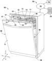
- FIG. 1 provides a perspective view of a dishwasher appliance, including a dishwasher door according to exemplary embodiments of the present disclosure.
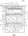
- FIG. 2 provides a cross-sectional side view of the exemplary dishwashing appliance of FIG. 1 .
- FIG. 3 illustrates a method for responding to abnormal button interactions with a user interface panel of a dishwasher appliance in accordance with one embodiment of the present disclosure.
- FIG. 4 provides a flow diagram illustrating an exemplary process for responding to abnormal button interactions according to an exemplary embodiment of the present subject matter.
- the terms “first,” “second,” and “third” may be used interchangeably to distinguish one component from another and are not intended to signify location or importance of the individual components.
- the term “or” is generally intended to be inclusive (i.e., “A or B” is intended to mean “A or B or both”).
- terms of approximation such as “approximately,” “substantially,” or “about,” refer to being within a ten percent margin of error.
- FIGS. 1 and 2 depict an exemplary domestic dishwashing appliance or dishwasher 100 that may be configured in accordance with aspects of the present disclosure.
- the dishwasher 100 includes a cabinet 102 having a tub 104 therein that defines a wash chamber 106 .
- tub 104 extends between a top 107 and a bottom 108 along a vertical direction V, between a pair of side walls 110 along a lateral direction L, and between a front side 111 and a rear side 112 along a transverse direction T.
- Each of the vertical direction V, lateral direction L, and transverse direction T are mutually orthogonal to one another.
- the tub 104 includes a front opening 114 and a door 116 hinged at its bottom for movement between a normally closed vertical position (shown in FIG. 2 ), wherein the wash chamber 106 is sealed shut for washing operation, and a horizontal open position for loading and unloading of articles from the dishwasher 100 .
- dishwasher 100 further includes a door closure mechanism or assembly 118 that is used to lock and unlock door 116 for accessing and sealing wash chamber 106 .
- tub side walls 110 may accommodate a plurality of rack assemblies. More specifically, guide rails 120 may be mounted to side walls 110 for supporting a lower rack assembly 122 , a middle rack assembly 124 , and an upper rack assembly 126 . As illustrated, upper rack assembly 126 is positioned at a top portion of wash chamber 106 above middle rack assembly 124 , which is positioned above lower rack assembly 122 along the vertical direction V. Each rack assembly 122 , 124 , 126 is adapted for movement between an extended loading position (not shown) in which the rack is substantially positioned outside the wash chamber 106 , and a retracted position (shown in FIGS. 1 and 2 ) in which the rack is located inside the wash chamber 106 .
- rollers 128 mounted onto rack assemblies 122 , 124 , 126 , respectively.
- a guide rails 120 and rollers 128 are illustrated herein as facilitating movement of the respective rack assemblies 122 , 124 , 126 , it should be appreciated that any suitable sliding mechanism or member may be used according to alternative embodiments.
- rack assemblies 122 , 124 , 126 are fabricated into lattice structures including a plurality of wires or elongated members 130 (for clarity of illustration, not all elongated members making up rack assemblies 122 , 124 , 126 are shown in FIG. 2 ).
- rack assemblies 122 , 124 , 126 are generally configured for supporting articles within wash chamber 106 while allowing a flow of wash fluid to reach and impinge on those articles (e.g., during a cleaning or rinsing cycle).
- a silverware basket (not shown) may be removably attached to a rack assembly (e.g., lower rack assembly 122 ) for placement of silverware, utensils, and the like, that are otherwise too small to be accommodated by rack 122 .
- rack assembly e.g., lower rack assembly 122
- Dishwasher 100 further includes a plurality of spray assemblies for urging a flow of water or wash fluid onto the articles placed within wash chamber 106 . More specifically, as illustrated in FIG. 2 , dishwasher 100 includes a lower spray arm assembly 134 disposed in a lower region 136 of wash chamber 106 and above a sump 138 so as to rotate in relatively close proximity to lower rack assembly 122 . Similarly, a mid-level spray arm assembly 140 is located in an upper region of wash chamber 106 and may be located below and in close proximity to middle rack assembly 124 . In this regard, mid-level spray arm assembly 140 may generally be configured for urging a flow of wash fluid up through middle rack assembly 124 and upper rack assembly 126 .
- an upper spray assembly 142 may be located above upper rack assembly 126 along the vertical direction V. In this manner, upper spray assembly 142 may be configured for urging or cascading a flow of wash fluid downward over rack assemblies 122 , 124 , and 126 . As further illustrated in FIG. 2 , upper rack assembly 126 may further define an integral spray manifold 144 , which is generally configured for urging a flow of wash fluid substantially upward along the vertical direction V through upper rack assembly 126 .
- fluid circulation assembly 150 for circulating water and wash fluid in the tub 104 .
- fluid circulation assembly 150 includes a pump 152 for circulating water or wash fluid (e.g., detergent, water, or rinse aid) in the tub 104 .
- Pump 152 may be located within sump 138 or within a machinery compartment located below sump 138 of tub 104 , as generally recognized in the art.
- Fluid circulation assembly 150 may include one or more fluid conduits or circulation piping for directing water or wash fluid from pump 152 to the various spray assemblies and manifolds.
- a primary supply conduit 154 may extend from pump 152 , along rear 112 of tub 104 along the vertical direction V to supply wash fluid throughout wash chamber 106 .
- primary supply conduit 154 is used to supply wash fluid to one or more spray assemblies (e.g., to mid-level spray arm assembly 140 and upper spray assembly 142 ).
- any other suitable plumbing configuration may be used to supply wash fluid throughout the various spray manifolds and assemblies described herein.
- primary supply conduit 154 could be used to provide wash fluid to mid-level spray arm assembly 140 and a dedicated secondary supply conduit (not shown) could be utilized to provide wash fluid to upper spray assembly 142 .
- Other plumbing configurations may be used for providing wash fluid to the various spray devices and manifolds at any location within dishwasher appliance 100 .
- Each spray arm assembly 134 , 140 , 142 , integral spray manifold 144 , or other spray device may include an arrangement of discharge ports or orifices for directing wash fluid received from pump 152 onto dishes or other articles located in wash chamber 106 .
- the arrangement of the discharge ports also referred to as jets, apertures, or orifices, may provide a rotational force by virtue of wash fluid flowing through the discharge ports.
- spray arm assemblies 134 , 140 , 142 may be motor-driven, or may operate using any other suitable drive mechanism.
- Spray manifolds and assemblies may also be stationary. The resultant movement of the spray arm assemblies 134 , 140 , 142 and the spray from fixed manifolds provides coverage of dishes and other dishwasher contents with a washing spray.
- dishwasher 100 may have additional spray assemblies for cleaning silverware, for scouring casserole dishes, for spraying pots and pans, for cleaning bottles, etc.
- additional spray assemblies for cleaning silverware, for scouring casserole dishes, for spraying pots and pans, for cleaning bottles, etc.
- diverter assembly 156 may include a diverter disk (not shown) disposed within a diverter chamber 158 for selectively distributing the wash fluid to the spray arm assemblies 134 , 140 , 142 or other spray manifolds or devices.
- the diverter disk may have a plurality of apertures that are configured to align with one or more outlet ports (not shown) at the top of diverter chamber 158 . In this manner, the diverter disk may be selectively rotated to provide wash fluid to the desired spray device.
- diverter assembly 156 is configured for selectively distributing the flow of wash fluid from pump 152 to various fluid supply conduits, only some of which are illustrated in FIG. 2 for clarity. More specifically, diverter assembly 156 may include four outlet ports (not shown) for supplying wash fluid to a first conduit for rotating lower spray arm assembly 134 in the clockwise direction, a second conduit for rotating lower spray arm assembly 134 in the counter-clockwise direction, a third conduit for spraying an auxiliary rack such as the silverware rack, and a fourth conduit for supply mid-level or upper spray assemblies 140 , 142 (e.g., such as primary supply conduit 154 ).
- the dishwasher 100 is further equipped with a controller 160 to regulate operation of the dishwasher 100 .
- the controller 160 may include one or more memory devices and one or more microprocessors, such as general or special purpose microprocessors operable to execute programming instructions or micro-control code associated with a cleaning cycle.
- the memory may represent random access memory such as DRAM, or read only memory such as ROM or FLASH.
- the processor executes programming instructions stored in memory.
- the memory may be a separate component from the processor or may be included onboard within the processor.
- controller 160 may be constructed without using a microprocessor (e.g., using a combination of discrete analog or digital logic circuitry, such as switches, amplifiers, integrators, comparators, flip-flops, AND gates, and the like) to perform control functionality instead of relying upon software.
- a microprocessor e.g., using a combination of discrete analog or digital logic circuitry, such as switches, amplifiers, integrators, comparators, flip-flops, AND gates, and the like
- the controller 160 may be positioned in a variety of locations throughout dishwasher 100 .
- the controller 160 may be located within a control panel area 162 of door 116 , as shown in FIGS. 1 and 2 .
- input/output (“I/O”) signals may be routed between the control system and various operational components of dishwasher 100 along wiring harnesses that may be routed through the bottom of door 116 .
- the controller 160 may be in operative communication with a user interface panel 164 through which a user may select various operational features and modes and monitor progress of the dishwasher 100 .
- the user interface 164 may represent a general purpose I/O (“GPIO”) device or functional block.
- GPIO general purpose I/O
- the user interface 164 includes input components 166 , such as one or more of a variety of electrical, mechanical or electro-mechanical input devices including capacitive touch screens/buttons, rotary dials, push buttons, and touch pads.
- the user interface 164 may further include one or more display components 168 , such as a digital display device or one or more indicator light assemblies designed to provide operational feedback to a user.
- the user interface 164 may be in communication with the controller 160 via one or more signal lines or shared communication busses.
- FIGS. 1 and 2 The exemplary embodiment depicted in FIGS. 1 and 2 is for illustrative purposes only. For example, different locations may be provided for user interface 164 , different configurations may be provided for rack assemblies 122 , 124 , 126 , different spray arm assemblies 134 , 140 , 142 and spray manifold configurations may be used, and other differences may be applied while remaining within the scope of the present subject matter. Moreover, aspects of the present subject matter may be applied to other appliances as well, such as refrigerators, ovens, microwaves, etc.
- door 116 will be described according to exemplary embodiments of the present subject matter.
- door 116 is described herein as being used with dishwasher 100 , it should be appreciated that door 116 or variations thereof may be used on any other suitable residential or commercial appliance.
- door 116 may share a coordinate system with dishwasher 100 , e.g., when door 116 is in the closed position (e.g., as shown in FIG. 2 ).
- door 116 may define a vertical direction V, a lateral direction L, and a transverse direction T. Therefore, these directions may be used herein to refer to features of door 116 and its various components and sub-assemblies.
- door 116 extends from a top end or top edge 180 to a bottom end or bottom edge 182 along the vertical direction V; from a front end 184 to a rear end 186 along the transverse direction T; and between two lateral ends 188 along the lateral direction L.
- door 116 may be formed from one or more exterior panels that define an interior chamber of door 116 .
- the exterior panels of door 116 may be panels that are stamped from stainless steel or may be formed from any other suitably rigid material, such as thermoformed plastic, other metals, etc.
- the exterior panels of door 116 may be assembled in any suitable manner, e.g., may be secured together using any suitable mechanical fastener, welding, snap-fit mechanisms, etc.
- an insulating material (not shown), such as fiberglass or foam insulation, may be positioned within door 116 to provide thermal and/or sound insulation to dishwasher 100 .
- user interface panel 164 is positioned proximate top edge 180 of door 116 along the vertical direction V. In this manner, user interface panel 164 may be partially hidden below a countertop when dishwasher appliance 100 is installed below the countertop and door 116 is closed. Accordingly, dishwasher appliance 100 may be referred to as a “top control dishwasher appliance.” However, it should be appreciated that aspects of the present subject matter may be used with dishwasher appliances having other configurations or any other suitable appliance. For example, user interface panel 164 may be alternately positioned on front face or front end 184 of door 116 .
- User interface panel 164 is positioned on door 116 such that a user can engage or interact with user interface panel 164 , e.g., to select operating cycles and parameters, activate/deactivate operating cycles, or adjust other operating parameters of dishwasher appliance 100 .
- User interface panel 164 may include a printed circuit board (not shown) that is positioned within door 116 . According to exemplary embodiments, printed circuit board may include or be operatively coupled to controller 160 and/or user interface panel 164 .
- user interface panel 164 may include or be operably coupled to one or more user inputs or touch buttons (e.g., identified generally herein as user inputs 166 ) for receiving user input, providing user notifications, or illuminating to indicate cycle or operating status.
- user inputs 166 include a plurality of capacitive sensors that are mounted to user interface panel 164 and are operable to detect user inputs.
- these capacitive sensors may be configured for triggering when a user touches a top edge 180 of user interface panel 164 in a region associated with a particular user input 166 .
- these capacitive sensors can detect when a finger or another conductive material with a dielectric different than air contacts or approaches user interface panel 164 , along with the precise location, pressure, etc. of the finger interaction.
- the associated capacitive sensors may be triggered and may communicate a corresponding signal to controller 160 .
- operations of dishwasher appliance 100 can be initiated and controlled.
- the capacitive sensors may be distributed laterally on user interface panel 164 . It will be understood that other any suitable number, type, and position of capacitive sensors may be used while remaining within the scope of the present subject matter. Indeed, any suitable number, type, and configuration of user inputs 166 may be used while remaining within the scope of the present subject matter.
- User interface panel 164 may define a plurality of surfaces that are intended to be illuminated for various purposes.
- user inputs 166 may be illuminated by light sources to inform the user of the location of the button or to provide some other status indication. Notably, this illumination is typically achieved by directing a light beam along the vertical direction V onto top edge 180 of user interface panel 164 .
- Door 116 may further include a plurality of light sources or lighting devices that are configured for illuminating one or more surfaces of user interface panel 164 . It should be appreciated that these light sources may include any suitable number, type, configuration, and orientation of light sources mounted at any suitable location to illuminate status indicators or buttons in any suitable colors, sizes, patterns, etc.
- the light sources may be provided as any suitable number, type, position, and configuration of electrical light source(s), using any suitable light technology and illuminating in any suitable color.
- the light sources may include one or more light emitting diodes (LEDs), which may each illuminate in a single color (e.g., white LEDs), or which may each illuminate in multiple colors (e.g., multi-color or RGB LEDs) depending on the control signal from controller 160 .
- LEDs light emitting diodes
- the light sources may include any other suitable traditional light bulbs or sources, such as halogen bulbs, fluorescent bulbs, incandescent bulbs, glow bars, a fiber light source, etc.
- the light sources may be operably coupled (e.g., electrically coupled) to controller 160 or another suitable control board to facilitate activation or illumination of the light sources (e.g., to indicate a user input, state of the dishwasher appliance, state of the wash cycle, or any other relevant information to a user).
- user interface panel 164 may be any suitable transparent or semitransparent feature for diffusing, directing, or otherwise transmitting light from a light source.
- user interface panel 164 may be formed from a suitable transparent or translucent material configured to direct light energy, such as a dielectric material, such as glass or plastic, polycarbonate, polypropylene, polyacrylic, or any other suitable material.
- user interface panel 164 may be a dead fronted panel.
- the term “dead front” and the like is generally intended to refer to portions of a control panel which may be used as indicators, buttons, interactive control surfaces, or other user-interaction features without exposing the user to the operating side of the equipment or live parts and connections, i.e., lights, electrical connections, etc.
- user interface panel 164 may include a transparent or translucent body and an opaque masking material that is selectively printed on top edge 180 of the translucent body to define capacitive touch buttons or user inputs 166 .
- the opaque material may be deposited on the translucent body to define any suitable number, size, and configuration of illuminated features. These illuminated features may be shapes or include other forms such as symbols, words, etc. that are visible on user interface panel 164 . More specifically, when light sources are energized, capacitive touch buttons or user inputs 166 on top edge 180 may be illuminated. Thus, the dead fronted top edge 180 may be the surface that is contacted for controlling dishwasher appliance 100 or which may be illuminated for purposes of indicating operating status or other conditions to the user of the dishwasher appliance 100 .
- external communication system 190 is configured for permitting interaction, data transfer, and other communications between dishwasher appliance 100 and one or more external devices.
- this communication may be used to provide and receive operating parameters, user instructions or notifications, performance characteristics, user preferences, or any other suitable information for improved performance of dishwasher appliance 100 .
- external communication system 190 may be used to transfer data or other information to improve performance of one or more external devices or appliances and/or improve user interaction with such devices.
- external communication system 190 permits controller 160 of dishwasher appliance 100 to communicate with a separate device external to dishwasher appliance 100 , referred to generally herein as an external device 192 . As described in more detail below, these communications may be facilitated using a wired or wireless connection, such as via a network 194 .
- external device 192 may be any suitable device separate from dishwasher appliance 100 that is configured to provide and/or receive communications, information, data, or commands from a user.
- external device 192 may be, for example, a personal phone, a smartphone, a tablet, a laptop or personal computer, a wearable device, a smart home system, or another mobile or remote device.
- a remote server 196 may be in communication with dishwasher appliance 100 and/or external device 192 through network 194 .
- remote server 196 may be a cloud-based server 196 , and is thus located at a distant location, such as in a separate state, country, etc.
- external device 192 may communicate with a remote server 196 over network 194 , such as the Internet, to transmit/receive data or information, provide user inputs, receive user notifications or instructions, interact with or control dishwasher appliance 100 , etc.
- external device 192 and remote server 196 may communicate with dishwasher appliance 100 to communicate similar information.
- communication between dishwasher appliance 100 , external device 192 , remote server 196 , and/or other user devices or appliances may be carried using any type of wired or wireless connection and using any suitable type of communication network, non-limiting examples of which are provided below.
- external device 192 may be in direct or indirect communication with dishwasher appliance 100 through any suitable wired or wireless communication connections or interfaces, such as network 194 .
- network 194 may include one or more of a local area network (LAN), a wide area network (WAN), a personal area network (PAN), the Internet, a cellular network, any other suitable short- or long-range wireless networks, etc.
- communications may be transmitted using any suitable communications devices or protocols, such as via Wi-Fi®, Bluetooth®, Zigbee®, wireless radio, laser, infrared, Ethernet type devices and interfaces, etc.
- communications may use a variety of communication protocols (e.g., TCP/IP, HTTP, SMTP, FTP), encodings or formats (e.g., HTML, XML), and/or protection schemes (e.g., VPN, secure HTTP, SSL).
- External communication system 190 is described herein according to an exemplary embodiment of the present subject matter. However, it should be appreciated that the exemplary functions and configurations of external communication system 190 provided herein are used only as examples to facilitate description of aspects of the present subject matter. System configurations may vary, other communication devices may be used to communicate directly or indirectly with one or more associated appliances, other communication protocols and steps may be implemented, etc. These variations and modifications are contemplated as within the scope of the present subject matter.
- dishwasher appliance 100 and user interface panel 164 an exemplary method 200 of operating a dishwasher appliance will be described.
- the discussion below refers to the exemplary method 200 of operating dishwasher appliance 100
- the exemplary method 200 is applicable to the operation of a variety of other dishwasher appliances, such as front control dishwashers.
- aspects of the present subject matter may be applicable to the operation of any user interface panel on any suitable appliance.
- the various method steps as disclosed herein may be performed by controller 160 or a separate, dedicated controller.
- method 200 includes, at step 210 , detecting an abnormal button interaction with a user interface panel of a dishwasher appliance.
- interactions with the user interface panel 164 may be continuously monitored by controller 160 of dishwasher appliance 100 .
- a user may press one or more user inputs 166 on user interface panel 164 to select operating cycles, adjust operating parameters, initiate operation, etc.
- certain interactions with user interface panel 164 may be considered abnormal, unusual, or potentially unintentional. Accordingly, aspects of the present subject matter are directed to methods for dealing with such abnormal button interactions.
- detecting the abnormal button interaction may include measuring a button interaction time and determining that the button interaction time falls outside of a predetermined time range.
- controller 160 may monitor or may be programmed with button interaction times associated with normal appliance operation. For example, a user may typically press a button for a specific duration, and controller 160 may associate that duration or a specific range around that duration as the predetermined time range.
- the predetermined time range may be between about 10 milliseconds and 2 seconds, between about 50 milliseconds and 1.5 seconds, between about 100 milliseconds and 1 second, between about 200 milliseconds and 800 milliseconds, between about 400 milliseconds and 600 milliseconds, or any other suitable time range. If the button interaction time falls outside of the predetermined time range, controller 160 may determine that the button interaction was abnormal. Other suitable button interaction time ranges are possible and within the scope of the present subject matter.
- controller 160 may trigger the abnormal button interaction, e.g., as this may be indicative of an unintentional tap of a finger, brushing a hand, or brief contact with another object.
- controller 160 may again determine this interaction is an abnormal button interaction.
- detecting the abnormal button interaction may include determining that the abnormal button interaction comprises simultaneously pressing multiple buttons on the user interface panel.
- a typical user input would include a single finger touching a single button for a specific time and with a specific pressure. Variations on the interaction time and pressure may be indicative of an abnormal button interaction.
- the controller may consider this an abnormal button interaction. For example, if two adjacent user inputs 166 are simultaneously touched or activated, this may indicate that the user was wishing to push only one of those buttons or that a user was leaning against the user interface panel 164 .
- detecting the abnormal button interaction may include determining that the abnormal button interaction includes predetermined sequence of button presses on the user interface panel. For example, if controller 160 senses that a series of user inputs 166 have been activated in a sequential manner going from left to right on user interface panel 164 , this may indicate that a user unintentionally swiped their hand or finger across user interface panel 164 . Alternatively, this interaction may be indicative of liquid splashing along the user interface panel 164 or another object interacting with user interface panel 164 . In these situations, controller 160 may consider the interaction abnormal and may raise the abnormal button interaction flag. Although exemplary abnormal button interactions are described herein, it should be appreciated that additional abnormal button interactions may be used while remaining within scope the present subject matter.
- step 220 may include determining that at least one operating parameter has changed in response to the abnormal button interaction.
- operating parameter and the like are generally intended to refer to any cycle setting, operating time, component setting, input parameter, cycle selection, control actions, or other operating characteristic that may affect the performance of dishwasher appliance 100 . Other operating parameter adjustments are possible and within the scope of the present subject matter.
- Step 220 may include controller 160 determining that any such operating parameter has changed as a result of the abnormal button interaction.
- Step 230 may generally include implementing a responsive action in response to determining that the at least one operating parameter has changed in response to the abnormal button interaction.
- step 230 may include automatically responding to such a change.
- step 230 may include reverting back to the prior operating parameter settings, i.e., before the abnormal button interaction resulted in a change in such operating parameters.
- implementing the responsive action may include providing a user notification that the at least one operating parameter has changed in response to the abnormal button interaction.
- controller 160 may make the user of dishwasher appliance 100 aware of the situation such that they may take corrective action.
- controller 160 may communicate with the user of dishwasher appliance 100 in any suitable manner.
- controller 160 may be in operative communication with a remote device through an external network (e.g., such as remote device 192 ).
- the user notification may be provided through the remote device which may include a mobile phone, a smart speaker, a tablet, or any other suitable device.
- implementing the responsive action may include seeking a user confirmation or approval as to the detected abnormal button interaction.
- method 200 may include receiving a user confirmation that the abnormal button interaction was intentional and implementing an operating cycle in accordance with the change in the at least one operating parameter.
- controller 160 may notify the user (e.g., via display 168 or remote device 192 ) as to the button selection and that it was flagged as abnormal. The user may review the button selection and may confirm that it was intended and should be implemented. In response, controller 160 may implement the abnormal button interaction.
- implementing the responsive action may include receiving a user confirmation that the abnormal button interaction was unintentional and adjusting the at least one operating parameter to a prior parameter setting in response.
- controller 160 may revert any changed parameter settings back to their prior setting, or may reverse or correct any other action taken in response to the abnormal button interaction.
- method 300 may be similar to or interchangeable with method 200 and may be implemented by controller 160 of dishwasher appliance 100 .
- process for responding to abnormal button interactions 300 may be used within any other suitable appliance.
- controller 160 may determine whether there has been an abnormal button interaction with user interface panel 164 . If the button interaction is considered normal, step 304 may include continuing the cycle as designed, e.g., in accordance with the user input. By contrast, if the button interaction is deemed abnormal, step 306 may include determining whether there was a change in the cycle, options, or cycle parameters from the prior operating cycle. If there was no change in operating parameters, step 308 may include continuing the cycle as designed. In this regard, if the abnormal button interaction results in no change in operating parameters and thus no difference in the appliance operation, controller 160 may perform the operating cycle without interacting with the user.
- step 310 may include providing a user notification or otherwise alerting the consumer to seek confirmation and inform them of the change in operating parameters.
- Step 312 may include seeking user confirmation regarding the intentionality of the abnormal button interaction. If the user indicates that the abnormal button interaction was in fact intentional, step 314 may include implementing the abnormal button interaction and continuing the cycle as designed. By contrast, if the user indicates that the abnormal button interaction was unintentional, step 316 may include automatically returning the cycle and option settings to the settings used prior to the abnormal button interaction.
- FIGS. 3 and 4 depict steps performed in a particular order for purposes of illustration and discussion. Those of ordinary skill in the art, using the disclosures provided herein, will understand that the steps of any of the methods discussed herein can be adapted, rearranged, expanded, omitted, or modified in various ways without deviating from the scope of the present disclosure. Moreover, although aspects of method 200 and method 300 are explained using dishwasher appliance 100 as an example, it should be appreciated that this method may be applied to the operation of any suitable consumer or commercial appliance.
- aspects of the present subject matter are generally directed to methods for detecting unintentional interactions with a user interface panel of a dishwasher appliance and correcting appliance operation accordingly.
- the methods may include maintaining the same cycle and option settings for a dishwasher operating cycle whenever an unintentional change in the appliance settings is detected.
- dishwasher appliances may include capacitance touch controls that may be inadvertently pressed or activated, e.g., due to interaction with hands, shins, pets, etc. These interactions may unintentionally change cycle and option settings.
- aspects of the present subject matter are directed to detecting such unintentional interactions and implementing a desired response.
- Inadvertent or unintentional interactions may be detected in any suitable manner. For example, the amount of time that a button is actuated can be significantly different for these unintentional activations as compared to normal button selection.
- the dishwasher may not take the directed action and may instead generate a fault code or user notification. If an abnormal consumer interaction with a capacitive touch button is detected, the appliance may check to see if the cycle and option selections were changed during this abnormal button interaction. If there was an abnormal button interaction and a change in cycle/option selection resulted from such abnormal button interaction, then the user may be alerted and asked if the change was intentional. If the user confirms the change was intentional, the new settings may be updated, whereas the dishwasher may automatically return to the prior settings if the user confirms the interaction was unintentional.
Landscapes
- Washing And Drying Of Tableware (AREA)
Abstract
Description
Claims (18)
Priority Applications (1)
| Application Number | Priority Date | Filing Date | Title |
|---|---|---|---|
| US17/675,201 US11969128B2 (en) | 2022-02-18 | 2022-02-18 | System and method for detecting unintentional button activation and implementing an automatic response |
Applications Claiming Priority (1)
| Application Number | Priority Date | Filing Date | Title |
|---|---|---|---|
| US17/675,201 US11969128B2 (en) | 2022-02-18 | 2022-02-18 | System and method for detecting unintentional button activation and implementing an automatic response |
Publications (2)
| Publication Number | Publication Date |
|---|---|
| US20230263360A1 US20230263360A1 (en) | 2023-08-24 |
| US11969128B2 true US11969128B2 (en) | 2024-04-30 |
Family
ID=87573246
Family Applications (1)
| Application Number | Title | Priority Date | Filing Date |
|---|---|---|---|
| US17/675,201 Active US11969128B2 (en) | 2022-02-18 | 2022-02-18 | System and method for detecting unintentional button activation and implementing an automatic response |
Country Status (1)
| Country | Link |
|---|---|
| US (1) | US11969128B2 (en) |
Citations (5)
| Publication number | Priority date | Publication date | Assignee | Title |
|---|---|---|---|---|
| US20110181516A1 (en) | 2010-01-22 | 2011-07-28 | General Electric Company | Touch-screen control panel for a dishwasher |
| US8902172B2 (en) | 2006-12-07 | 2014-12-02 | Cypress Semiconductor Corporation | Preventing unintentional activation of a touch-sensor button caused by a presence of conductive liquid on the touch-sensor button |
| US20160077664A1 (en) | 2014-09-15 | 2016-03-17 | Qeexo, Co. | Method and apparatus for resolving touch screen ambiguities |
| US11009989B2 (en) | 2018-08-21 | 2021-05-18 | Qeexo, Co. | Recognizing and rejecting unintentional touch events associated with a touch sensitive device |
| US20210157408A1 (en) * | 2019-11-27 | 2021-05-27 | Immersion Corporation | Systems and methods for multi-directional haptic effects |
-
2022
- 2022-02-18 US US17/675,201 patent/US11969128B2/en active Active
Patent Citations (6)
| Publication number | Priority date | Publication date | Assignee | Title |
|---|---|---|---|---|
| US8902172B2 (en) | 2006-12-07 | 2014-12-02 | Cypress Semiconductor Corporation | Preventing unintentional activation of a touch-sensor button caused by a presence of conductive liquid on the touch-sensor button |
| US20110181516A1 (en) | 2010-01-22 | 2011-07-28 | General Electric Company | Touch-screen control panel for a dishwasher |
| US20160077664A1 (en) | 2014-09-15 | 2016-03-17 | Qeexo, Co. | Method and apparatus for resolving touch screen ambiguities |
| EP3195095B1 (en) | 2014-09-15 | 2021-04-28 | Qeexo, Co. | Method and apparatus for resolving touch screen ambiguities |
| US11009989B2 (en) | 2018-08-21 | 2021-05-18 | Qeexo, Co. | Recognizing and rejecting unintentional touch events associated with a touch sensitive device |
| US20210157408A1 (en) * | 2019-11-27 | 2021-05-27 | Immersion Corporation | Systems and methods for multi-directional haptic effects |
Also Published As
| Publication number | Publication date |
|---|---|
| US20230263360A1 (en) | 2023-08-24 |
Similar Documents
| Publication | Publication Date | Title |
|---|---|---|
| US10905304B2 (en) | User interface for appliance cycle optimization | |
| RU2406177C2 (en) | Domestic device and methods of its control | |
| US10307035B2 (en) | Dish treating appliance with leak detection | |
| US10478040B1 (en) | Handle assembly for an appliance door | |
| US10945582B1 (en) | Consumer appliances and methods of operation | |
| US10731918B1 (en) | Single-layer appliance indicator light with side-fire LED | |
| US11969128B2 (en) | System and method for detecting unintentional button activation and implementing an automatic response | |
| US20060164397A1 (en) | Appliance with membrane overlay | |
| US11006812B2 (en) | Status indicator and lighting assembly for an appliance door | |
| US11185212B2 (en) | Status indicator and lighting assembly for an appliance door | |
| US11278179B2 (en) | Status indicator and lighting assembly for an appliance door | |
| US20220151457A1 (en) | User interface console for an appliance providing clearance for an edge connector | |
| US10753597B1 (en) | Light blocking features for indicator lights in an appliance | |
| US20130174872A1 (en) | Prolonged operation heater protection in an appliance | |
| US11324382B2 (en) | Diverter assembly for a dishwasher appliance and a method of operating the same | |
| US10934654B1 (en) | Relay monitor circuit and secondary relay control for an appliance | |
| US20240423440A1 (en) | Dishwashing appliance and methods of operation for future cycle protection | |
| US11484182B2 (en) | Front indicator lighting assembly for an appliance door | |
| US10687686B2 (en) | Dishwasher appliance doors and light assemblies | |
| US20220337448A1 (en) | Connected household appliances with distributed cycle parameters | |
| US11984838B2 (en) | Direct current load identification system | |
| EP2591711A1 (en) | Virtual buttons | |
| US20230320558A1 (en) | Dishwashing appliances and sensor assemblies for detecting a position of an appliance door | |
| US11134826B2 (en) | Status indicator and lighting assembly for an appliance door | |
| US20240398202A1 (en) | Methods for suggesting operation of a dishwasher appliance |
Legal Events
| Date | Code | Title | Description |
|---|---|---|---|
| AS | Assignment |
Owner name: HAIER US APPLIANCE SOLUTIONS, INC., DELAWARE Free format text: ASSIGNMENT OF ASSIGNORS INTEREST;ASSIGNOR:HOFMANN, ADAM CHRISTOPHER;REEL/FRAME:059046/0919 Effective date: 20220215 |
|
| FEPP | Fee payment procedure |
Free format text: ENTITY STATUS SET TO UNDISCOUNTED (ORIGINAL EVENT CODE: BIG.); ENTITY STATUS OF PATENT OWNER: LARGE ENTITY |
|
| STPP | Information on status: patent application and granting procedure in general |
Free format text: RESPONSE TO NON-FINAL OFFICE ACTION ENTERED AND FORWARDED TO EXAMINER |
|
| STPP | Information on status: patent application and granting procedure in general |
Free format text: FINAL REJECTION MAILED |
|
| STPP | Information on status: patent application and granting procedure in general |
Free format text: RESPONSE AFTER FINAL ACTION FORWARDED TO EXAMINER |
|
| STPP | Information on status: patent application and granting procedure in general |
Free format text: NOTICE OF ALLOWANCE MAILED -- APPLICATION RECEIVED IN OFFICE OF PUBLICATIONS |
|
| ZAAB | Notice of allowance mailed |
Free format text: ORIGINAL CODE: MN/=. |
|
| STPP | Information on status: patent application and granting procedure in general |
Free format text: PUBLICATIONS -- ISSUE FEE PAYMENT VERIFIED |
|
| STCF | Information on status: patent grant |
Free format text: PATENTED CASE |