US11920929B2 - Detecting and guiding optical connection(s) for one or more imaging modalities, such as in optical coherence tomography - Google Patents
Detecting and guiding optical connection(s) for one or more imaging modalities, such as in optical coherence tomography Download PDFInfo
- Publication number
- US11920929B2 US11920929B2 US17/354,241 US202117354241A US11920929B2 US 11920929 B2 US11920929 B2 US 11920929B2 US 202117354241 A US202117354241 A US 202117354241A US 11920929 B2 US11920929 B2 US 11920929B2
- Authority
- US
- United States
- Prior art keywords
- engagement
- peak
- disengagement
- catheter
- probe
- Prior art date
- Legal status (The legal status is an assumption and is not a legal conclusion. Google has not performed a legal analysis and makes no representation as to the accuracy of the status listed.)
- Active, expires
Links
Images


Classifications
-
- G—PHYSICS
- G01—MEASURING; TESTING
- G01B—MEASURING LENGTH, THICKNESS OR SIMILAR LINEAR DIMENSIONS; MEASURING ANGLES; MEASURING AREAS; MEASURING IRREGULARITIES OF SURFACES OR CONTOURS
- G01B9/00—Measuring instruments characterised by the use of optical techniques
- G01B9/02—Interferometers
- G01B9/0209—Low-coherence interferometers
- G01B9/02091—Tomographic interferometers, e.g. based on optical coherence
-
- A—HUMAN NECESSITIES
- A61—MEDICAL OR VETERINARY SCIENCE; HYGIENE
- A61B—DIAGNOSIS; SURGERY; IDENTIFICATION
- A61B1/00—Instruments for performing medical examinations of the interior of cavities or tubes of the body by visual or photographical inspection, e.g. endoscopes; Illuminating arrangements therefor
- A61B1/00131—Accessories for endoscopes
-
- A—HUMAN NECESSITIES
- A61—MEDICAL OR VETERINARY SCIENCE; HYGIENE
- A61B—DIAGNOSIS; SURGERY; IDENTIFICATION
- A61B1/00—Instruments for performing medical examinations of the interior of cavities or tubes of the body by visual or photographical inspection, e.g. endoscopes; Illuminating arrangements therefor
- A61B1/00147—Holding or positioning arrangements
- A61B1/00154—Holding or positioning arrangements using guiding arrangements for insertion
-
- A—HUMAN NECESSITIES
- A61—MEDICAL OR VETERINARY SCIENCE; HYGIENE
- A61B—DIAGNOSIS; SURGERY; IDENTIFICATION
- A61B1/00—Instruments for performing medical examinations of the interior of cavities or tubes of the body by visual or photographical inspection, e.g. endoscopes; Illuminating arrangements therefor
- A61B1/00163—Optical arrangements
-
- G—PHYSICS
- G01—MEASURING; TESTING
- G01B—MEASURING LENGTH, THICKNESS OR SIMILAR LINEAR DIMENSIONS; MEASURING ANGLES; MEASURING AREAS; MEASURING IRREGULARITIES OF SURFACES OR CONTOURS
- G01B9/00—Measuring instruments characterised by the use of optical techniques
- G01B9/02—Interferometers
- G01B9/02015—Interferometers characterised by the beam path configuration
- G01B9/02027—Two or more interferometric channels or interferometers
- G01B9/02028—Two or more reference or object arms in one interferometer
-
- G—PHYSICS
- G01—MEASURING; TESTING
- G01B—MEASURING LENGTH, THICKNESS OR SIMILAR LINEAR DIMENSIONS; MEASURING ANGLES; MEASURING AREAS; MEASURING IRREGULARITIES OF SURFACES OR CONTOURS
- G01B9/00—Measuring instruments characterised by the use of optical techniques
- G01B9/02—Interferometers
- G01B9/02049—Interferometers characterised by particular mechanical design details
-
- G—PHYSICS
- G06—COMPUTING OR CALCULATING; COUNTING
- G06T—IMAGE DATA PROCESSING OR GENERATION, IN GENERAL
- G06T7/00—Image analysis
- G06T7/30—Determination of transform parameters for the alignment of images, i.e. image registration
- G06T7/33—Determination of transform parameters for the alignment of images, i.e. image registration using feature-based methods
-
- G—PHYSICS
- G06—COMPUTING OR CALCULATING; COUNTING
- G06T—IMAGE DATA PROCESSING OR GENERATION, IN GENERAL
- G06T2207/00—Indexing scheme for image analysis or image enhancement
- G06T2207/10—Image acquisition modality
- G06T2207/10072—Tomographic images
- G06T2207/10101—Optical tomography; Optical coherence tomography [OCT]
Definitions
- the present disclosure relates generally to the field of imaging and more particularly to one or more optical apparatuses, systems, methods (for using and/or manufacturing) and storage mediums, such as, but not limited to, fiber optic catheters, endoscopes and/or optical coherence tomography (OCT) and/or fluorescence apparatuses and systems, and methods and storage mediums, for use with same, to detect, monitor, and/or guide mating of a probe/catheter to such apparatuses, systems, and/or storage mediums, etc. when obtaining image(s) for one or more imaging modalities, such as OCT or other (e.g., intravascular ultrasound (IVUS), other lumen image(s), etc.).
- OCT optical coherence tomography
- fluorescence apparatuses and systems and methods and storage mediums, for use with same, to detect, monitor, and/or guide mating of a probe/catheter to such apparatuses, systems, and/or storage mediums, etc.
- Examples of such applications include imaging, evaluating and diagnosing biological objects, such as, but not limited to, gastro-intestinal, pulmonary, cardio, ophthalmic, and/or intravascular applications, and being obtained via one or more optical instruments, such as, but not limited to, one or more optical probes, one or more catheters, one or more endoscopes, one or more phase shift units (e.g., galvanometer scanner), one or more tethered capsules, one or more needles (e.g., a biopsy needle), and one or more bench top systems.
- optical instruments such as, but not limited to, one or more optical probes, one or more catheters, one or more endoscopes, one or more phase shift units (e.g., galvanometer scanner), one or more tethered capsules, one or more needles (e.g., a biopsy needle), and one or more bench top systems.
- Fiber optic catheters and endoscopes have been developed to access to internal organs.
- OCT has been developed to see depth resolved images of vessels with a catheter.
- the catheter which may include a sheath, a coil and an optical probe, may be navigated to a coronary artery.
- Optical coherence tomography is a technique for obtaining high-resolution cross-sectional images of tissues or materials, and enables real time visualization.
- the aim of the OCT techniques is to measure the time delay of light by using an interference optical system or interferometry, such as via Fourier Transform or Michelson interferometers.
- a light from a light source delivers and splits into a reference arm and a sample (or measurement) arm with a splitter (e.g., a beamsplitter).
- a reference beam is reflected from a reference mirror (partially reflecting or other reflecting element) in the reference arm while a sample beam is reflected or scattered from a sample in the sample arm.
- Both beams combine (or are recombined) at the splitter and generate interference patterns.
- the output of the interferometer is detected with one or more detectors, such as, but not limited to, photodiodes or multi-array cameras, in one or more devices, such as, but not limited to, a spectrometer (e.g., a Fourier Transform infrared spectrometer).
- the interference patterns are generated when the path length of the sample arm matches that of the reference arm to within the coherence length of the light source.
- a spectrum of an input radiation may be derived as a function of frequency.
- the frequency of the interference patterns corresponds to the distance between the sample arm and the reference arm. The higher frequencies are, the more the path length differences are.
- Single mode fibers may be used for OCT optical probes, and double clad fibers may be used for fluorescence and/or spectroscopy.
- IVI intravascular imaging
- IVUS intravascular ultrasound
- OCT optical coherence tomography
- IVI modalities provide cross-sectional imaging of coronary arteries with precise lesion information (e.g., lumen size, plaque morphology, implanted devices, etc.). That said, only about 20% of interventional cardiologists in the United States use IVI imaging in conjunction with coronary angiography during PCI procedures. Additionally, IVI imaging uses the mating of disposable single use sterile catheters or probes to non-disposable imaging systems.
- the mating process involves mechanically connecting the catheter/probe to a system to get an adequate electrical, optical, and/or radio frequency (RF) connection (e.g., in addition to or alternatively to a mechanical connection) depending on the type of catheter/probe.
- RF radio frequency
- a signal is very small, it may be hard to measure. Additionally, where a signal is not location specific (e.g., a signal may be from all reflections making it back to a system), it may be unclear if the signal is from a fully mated probe/catheter, a partially mated probe/catheter, or reflection(s) from an endface of a probe connector of the probe/catheter.
- a sensor may be used to determine if the probe/catheter is mechanically mated with a system
- drawbacks are that the use of the sensor uses an additional means or component(s) to interface with the sensor for each probe/catheter, and such a method is an indirect method of determining the mechanical connection and only determines if there is a mechanical connection.
- Interferometry methods such as OFDR (Optical Frequency Domain Reflectometer) and OTDR (Optical Time Domain Reflectometer) may be used in telecom networks to measure insertion loss and return loss from fiber optic interfaces including connectors.
- OFDR Optical Frequency Domain Reflectometer
- OTDR Optical Time Domain Reflectometer
- the drawback of this method is that it requires a specialized complex hardware to measure insertion loss and/or return loss signals from the interfaces. Additionally, these methods are not used to determine or guide a mating process since they are slow. Such methods also require a completely different instrument.
- Performing a pullback when a probe is not properly mated may yield useless or less useful data, and may cause a physician a lot of wasted time.
- the user unaware, may attempt to remove the probe/catheter from the system just to be left, for example, with the core connected to a patient interface unit (PIU) of the system, potentially rendering the system unusable and/or causing damage to the PIU.
- PIU patient interface unit
- detecting, monitoring, and guiding the mating step e.g., engagement, disengagement, etc.
- detecting, monitoring, and guiding the mating step would be desirable to increase likelihood of catheter/probe mating success (e.g., to reduce mating failure(s), to minimize mating failure(s), to avoid mating failure(s), etc.), to confirm mating status, and to reduce case delays and user frustration.
- imaging e.g., OCT, NIRAF, etc.
- systems, methods and storage mediums for using and/or controlling one or more imaging modalities and/or to detect, monitor, and/or guide a mating step or process of a probe/catheter with one or more imaging apparatuses, systems, storage mediums, etc.
- an interferometer e.g., spectral-domain OCT (SD-OCT), swept-source OCT (SS-OCT), multimodal OCT (MM-OCT), Intravascular Ultrasound (IVUS), Near-Infrared Autofluorescence (NIRAF), Near-Infrared Spectroscopy (NIRS), Near-Infrared Fluorescence (NIRF), therapy modality using light, sound, or other source of
- probe engagement status may be used to communicate status to a user and to allow specific apparatus and/or system functionality and/or to inhibit other apparatus and/or system functionality.
- One or more embodiments may obtain a direct analysis of a probe/catheter connection and/or mating process using at least one reliable optical interference signal.
- One or more embodiments may operate with or without prior knowledge of reflection strength(s) from probe/catheter distal reflections, and preferably do not require such knowledge of the reflection strength(s).
- One or more embodiments of the present disclosure may use an OCT signal at a PIU output connector to determine engagement/disengagement status, and/or may use an OCT signal about or for the PIU output connector and a catheter connector to guide an engagement/disengagement process (also referred to herein as an “engagement process” or a “mating step or process”).
- One or more features of the present disclosure may be employed or exercised using any OCT apparatus and/or system, and may be done so using only minor modifications to the reference arm where an apparatus and/or system uses a single reference arm path, one or more embodiments of a method or technique of the present disclosure may use two reference arm paths or the ability to sufficiently adjust reference arm delay so as to adjust the imaging FOV to be at either the main sample imaging location or at about the system distal-most point (mating location).
- One or more embodiments of a system for increasing imaging depth range may include: an OCT system; a reference reflection adjusted so that a reflection from a system mating connector is visible in an imaging field of view; and one or more processors that operate to determine if a catheter/probe is mated to the system mating connector.
- determining engagement status may include one or more of the following: (i) at a start of an engage process, an apparatus or system may switch from a main reference arm to an auxiliary reference arm; (ii) the apparatus or system may move a linear stage and a rotary motor to pre-engage positions; (iii) the apparatus or system may measure or use previously stored PIU output connector signal-to-noise ratio (SNR) pre-engagement; (iv) the apparatus or system may move the linear stage to an engage position; (v) the apparatus or system may measure PIU output connector SNR post-engagement; (vi) the apparatus or system may determine that the engagement is successful or acceptable if a Post-Engage SNR is different from the Pre-Engage SNR, and/or (vii) the apparatus or system confirms only one peak is present at or about the PIU output connector.
- SNR PIU output connector signal-to-noise ratio
- One or more embodiments may measure a peak instead.
- Crosstalk noise may be used as a metric.
- One or more embodiments may use data from measured peak and noise levels of a single or several A-lines.
- mechanical mating of a sacrificial interface to a catheter connector may be attempted.
- determining disengagement status may include one or more of the following: (i) at a start of a disengage process, an apparatus or system may switch from a main reference arm to an auxiliary reference arm; (ii) the apparatus or system may move a linear stage and a rotary motor to pre-disengage positions; (iii) the apparatus or system may measure or use previously stored PIU output connector signal-to-noise ratio pre-disengage (SNR); (iv) the apparatus or system may move the linear stage to a disengage position; (v) the apparatus or system may measure PIU output connector SNR post-disengagement; (vi) the apparatus or system may determine that the disengagement is successful or acceptable if a Post-Disengage SNR is different from the Pre-Disengage SNR, and/or (vii) the apparatus or system confirms a second peak is present at a distance from the PIU output connector about equal to the distance between pre-disengage and engage positions.
- One or more embodiments may measure a peak instead.
- Crosstalk noise may be used as a metric.
- One or more embodiments may use data from measured peak and noise levels of a single or several A-lines.
- mechanical disengaging of a sacrificial interface from a catheter connector may be attempted.
- guiding engagement may include one or more of the following: (i) at a start of an engage process, an apparatus or system may switch from a main reference arm to an auxiliary reference arm; (ii) the apparatus or system may move a linear stage and a rotary motor to pre-engage positions; (iii) the apparatus or system may slowly move the linear stage to an engage position while measuring distance between a PIU connector reflection and a catheter connector reflection; (iv) the apparatus or system may use distance between the two reflections (e.g., the PIU connector reflection and the catheter connector reflection) to guide and determine when the Engage position is reached; (v) the apparatus or system may pull back (e.g., slowly, at a predetermined speed, etc.) the linear stage to release mechanical connection tension and to determine connection status; and/or (vi) the apparatus or system may determine that the engagement is successful or acceptable (or is likely successful/acceptable) in a case where only one peak is present (e.g., at or about the PIU output connector); otherwise, the
- guiding disengagement may include one or more of the following: (i) at a start of a disengage process, an apparatus or system may switch from a main reference arm to an auxiliary reference arm; (ii) the apparatus or system may move a linear stage and a rotary motor to pre-disengage positions; (iii) the apparatus or system may move (e.g.
- the apparatus or system may pull off (e.g., slowly, at a predetermined speed, etc.) the linear stage from the Disengage position;
- the apparatus or system may confirm a second peak is present at a distance from a PIU output connector commensurate with the distance expected from pulling off the linear stage; and/or (vi) the apparatus or system may perform a second pull of the linear stage, and, in the event that two peaks are present and represent expected separation, then the disengage is likely successful or acceptable; otherwise, disengage is deemed unsuccessful, and the apparatus or system may repeat the steps from step (iii).
- One or more embodiments of the present disclosure may include one or more of the following: (i) an imaging system with an optical probe (e.g., where the imaging system may be configurable or may operate to switch between more than one reference arm); (ii) an auxiliary reference arm may be used to image using an OCT PIU Output Connector reflection; (iii) the auxiliary reference arm may be used to look at the PIU Output Connector to diagnose if/whether an Output Connector interface may benefit from replacement or maintenance (e.g., the interface may be dirty, damaged, etc.); and/or (iv) the auxiliary reference arm may be used to look at a PIU sacrificial connector to diagnose and/or aid catheter/probe engagement and/or disengagement.
- an imaging system with an optical probe e.g., where the imaging system may be configurable or may operate to switch between more than one reference arm
- an auxiliary reference arm may be used to image using an OCT PIU Output Connector reflection
- the auxiliary reference arm may be used to look at the
- One or more embodiments may include one or more of the following: (i) determining whether the sacrificial interface needs to be cleaned, maintained, or replaced (e.g., the interface may be dirty, damaged, etc.); (ii) using crosstalk noise as a metric for engagement and/or disengagement status; (iii) operating to work with lens-based connections in addition to or alternatively to connector-based connections; and/or (iv) using one or more features of different auxiliary arm embodiments discussed herein.
- using an imaging system with an optical probe may improve or provide an advantage of detection of a fiber probe connection.
- using interference light may permit detection of depth-resolved peaks.
- guiding connection and/or disconnection of a probe/catheter may improve or optimize the process and may increase or maximize a respective success rate(s) (e.g., for connection, for disconnection, for both, etc.).
- One or more embodiments may include or may also include checking for probe connector quality as the connector approaches.
- the auxiliary reference arm may be used to do one or more of the following: (i) look at a rotation or Rotary Junction (RJ) connector interface as well as sacrificial interface and RJ Optical interfaces; and/or (ii) determine optical health of the PIU and determine system optical performance in a predictable manner.
- RJ Rotary Junction
- One or more embodiments of the present disclosure detect, monitor, and/or guide a mating step (e.g., engagement, disengagement, etc.) or process of a probe/catheter.
- a mating step e.g., engagement, disengagement, etc.
- catheter/probe mating success is increased or maximized, mating success may be confirmed, and/or case delays and user frustration are reduced or minimized.
- intraluminal imaging may be used to acquire high-resolution cross-sectional images of tissues or materials, and to enable real time visualization.
- Intraluminal imaging may employ automatic connection and disconnection of an optical probe/catheter to an imaging system.
- knowing a status of the probe/catheter connection improves or maximizes system performance/functionality.
- One or more embodiments properly mate and/or confirm proper mating of the probe/catheter connection to yield useful data, and to improve or maximize time of a physician.
- One or more embodiments of the present disclosure of at least one procedure may be described using at least one or more flow diagram.
- the present disclosure describes one or more features of one or more embodiments of methods in detail, including, but not limited to, about how to detect a lumen edge pixel in an A-line, how to detect an initial lumen edge pixel candidate corresponding peak(s) in an A-line (e.g., using neighborhood connectivity to join peaks into one or more objects), how to identify the edge pixels caused by image artifacts in an OCT image, and how to form the final lumen edge of the imaged vessel.
- optical apparatuses, systems, methods (for using and/or manufacturing) and storage mediums such as, but not limited to, fiber optic catheters, endoscopes and/or optical coherence tomography (OCT) apparatuses and systems, and methods and storage mediums, for use with same, to achieve consistent, reliable detection and/or guidance results (e.g., determining engagement status, determining disengagement status, guiding engagement, guiding disengagement, etc.), including at a high efficiency, and at a reasonable cost of manufacture and maintenance.
- OCT optical coherence tomography
- One or more additional objects of the present disclosure are to one or more of: (i) avoid using global threshold(s) in a two-dimensional (2D) image in one or more embodiments; and/or (ii) combine pixel intensity values and the separated gradient along A-line values and gradient across the A-lines values together for edge detection to improve lumen edge detection accuracy in one or more embodiments and/or to improve detection of a reflection from one or more of the catheter, PIU, or an interface created by the catheter and PIU when connected or made to come together in one or more embodiments.
- 2D image processing may be decoupled into separated 1D signal processing, and an adaptive threshold may be used for each one dimensional (1D) signal (i.e., A-line) of the image in polar coordinate(s) for lumen edge detection.
- 1D one dimensional
- a one-dimensional A-line signal may reveal more information about the underlying signal. Lumen edge pixel and artifact pixels may be easily identified using the A-line signal.
- each one-dimensional data (A-line) has its own optimal threshold for lumen edge detection. Such feature(s) remove(s) the need of finding global optimal threshold(s) in a 2D image, and reduces the computation complexity.
- One or more of the subject features also reduce(s) the algorithm sensitivity to regional image intensity variation, and/or provides immunity to intensity variation due to the imaging angle and distance changes.
- an optical coherence tomography system for determining engagement and/or disengagement status and/or for guiding engagement and/or disengagement may include: a light source that operates to produce a light; an interference optical system that operates to: (i) receive and divide the light from the light source into a first light with which an object or sample is to be irradiated and a second reference light, (ii) send the second reference light for reflection off of a reference mirror of the interference optical system, and (iii) generate interference light by causing reflected or scattered light of the first light with which the object or sample has been irradiated and the reflected second reference light to combine or recombine, and/or to interfere, with each other, the interference light generating one or more interference patterns; and one or more detectors that operate to continuously acquire the interference light and/or the one or more interference patterns.
- a computer-readable storage medium may store at least one program that operates to cause one or more processors to execute a method for determining engagement and/or disengagement status and/or for guiding engagement and/or disengagement, where the method may include one or more steps discussed herein.
- apparatuses and systems, and methods and storage mediums for determining engagement and/or disengagement status and/or for guiding engagement and/or disengagement may further operate to characterize biological objects, such as, but not limited to, blood, mucus, tissue, etc.
- one or more embodiments of the method(s) for determining engagement and/or disengagement status and/or for guiding engagement and/or disengagement, and/or other methods, of the present disclosure may be used in other imaging systems, apparatuses or devices, where images are formed from signal reflection and scattering within tissue sample(s) using a scanning probe.
- IVI modalities such as IVUS
- IVI or IVUS images may be processed in addition to or instead of OCT images.
- One or more embodiments of the present disclosure may be used in clinical application(s), such as, but not limited to, intervascular imaging, atherosclerotic plaque assessment, cardiac stent evaluation, balloon sinuplasty, sinus stenting, arthroscopy, ophthalmology, ear research, veterinary use and research, etc.
- one or more technique(s) discussed herein may be employed to reduce the cost of at least one of manufacture and maintenance of the one or more apparatuses, devices, systems and storage mediums by reducing or minimizing a number of optical components and by virtue of the efficient techniques to cut down cost of use/manufacture of such apparatuses, devices, systems and storage mediums.
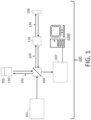
- FIG. 1 is a diagram showing an embodiment of a system which can utilize one or more engagement and/or disengagement status determination and/or engagement and/or disengagement guidance techniques in accordance with one or more aspects of the present disclosure
- FIG. 2 is a diagram of an embodiment of a catheter that may be used with at least one embodiment of an apparatus or system for performing engagement and/or disengagement status determination and/or engagement and/or disengagement guidance techniques in accordance with one or more aspects of the present disclosure
- FIGS. 3 A- 3 J are diagrams of respective apparatus/system embodiments for performing engagement and/or disengagement status determination and/or engagement and/or disengagement guidance techniques in accordance with one or more aspects of the present disclosure
- FIG. 4 is a graph showing average A-line as a function of depth in accordance with one or more aspects of the present disclosure
- FIG. 5 is a graph showing average A-line as a function of depth in accordance with one or more aspects of the present disclosure
- FIG. 6 is a graph showing average A-line as a function of depth in accordance with one or more aspects of the present disclosure
- FIG. 7 is a flow diagram illustrating at least one method embodiment of performing an engagement guiding and/or status determination feature, function or technique in accordance with one or more aspects of the present disclosure
- FIG. 8 is a flow diagram illustrating at least one method embodiment of performing an engagement guiding and/or status determination feature, function or technique in accordance with one or more aspects of the present disclosure
- FIG. 9 is a flow diagram illustrating at least one method embodiment of performing a disengagement guiding and/or status determination feature, function or technique in accordance with one or more aspects of the present disclosure
- FIG. 10 is a flow diagram illustrating at least one method embodiment of performing a disengagement guiding and/or status determination feature, function or technique in accordance with one or more aspects of the present disclosure
- FIG. 11 is a diagram showing an embodiment of at least another system which can utilize one or more engagement and/or disengagement status determination and/or engagement and/or disengagement guidance techniques in accordance with one or more aspects of the present disclosure
- FIG. 12 is a diagram showing an embodiment of at least a further system which can utilize one or more engagement and/or disengagement status determination and/or engagement and/or disengagement guidance techniques in accordance with one or more aspects of the present disclosure
- FIG. 13 is a diagram showing an embodiment of at least yet a further system which can utilize one or more engagement and/or disengagement status determination and/or engagement and/or disengagement guidance techniques in accordance with one or more aspects of the present disclosure
- FIG. 14 is a flow diagram illustrating at least one method embodiment of performing an imaging feature, function or technique that may be used with one or more engagement and/or disengagement status determination and/or engagement and/or disengagement guidance techniques in accordance with one or more aspects of the present disclosure
- FIG. 15 shows a schematic diagram of an embodiment of a computer that may be used with one or more embodiments of at least one apparatus, system, method, and/or storage medium, including, but not limited to, for performing one or more engagement and/or disengagement status determination and/or engagement and/or disengagement guidance techniques, in accordance with one or more aspects of the present disclosure
- FIG. 16 shows a schematic diagram of another embodiment of a computer that may be used with one or more embodiments of at least one apparatus, system, method, and/or storage medium, including, but not limited to, for performing one or more engagement and/or disengagement status determination and/or engagement and/or disengagement guidance techniques, in accordance with one or more aspects of the present disclosure.
- One or more devices/apparatuses, optical systems, methods, and storage mediums for performing engagement and/or disengagement status determination and/or engagement and/or disengagement guidance techniques are disclosed herein.
- FIG. 1 shows an OCT system 100 (as referred to herein as “system 100 ” or “the system 100 ”) which operates to utilize an OCT technique, including, but not limited to, one or more embodiments of engagement and/or disengagement status determination and/or engagement and/or disengagement guidance techniques discussed herein, with optical probe applications in accordance with one or more aspects of the present disclosure.
- the system 100 comprises a light source 101 , a reference arm 102 , a sample arm 103 , a splitter 104 (also referred to herein as a “beam splitter”), a reference mirror (also referred to herein as a “reference reflection”) 105 , and one or more detectors 107 .
- a splitter 104 also referred to herein as a “beam splitter”
- reference mirror also referred to herein as a “reference reflection”
- the system 100 may include a phase shift device or unit 130 , and, in one or more embodiments, the phase shift device or unit may be omitted.
- the system 100 may include a patient interface device or unit (“PIU”) 110 and a catheter 120 (as diagrammatically shown in FIGS. 1 - 2 ), and the system 100 may interact with a sample or target 106 (e.g., via the catheter/probe 120 and/or the PIU 110 ).
- PIU patient interface device or unit
- the system 100 includes an interferometer, or an interferometer is defined by one or more components of the system 100 , such as, but not limited to, at least the light source 101 , the reference arm 102 , the sample arm 103 , the splitter 104 , and the reference mirror 105 .
- the light source 101 operates to produce a light to the splitter 104 , which splits the light from the light source 101 into a reference beam passing into the reference arm 102 and a sample beam passing into the sample arm 103 .
- the beam splitter 104 is positioned or disposed at an angle to the reference mirror 105 , the one or more detectors 107 and to the sample or target 106 .
- the reference beam goes through the phase shift unit 130 (when included in a system, as shown in the system 100 ), and the reference beam is reflected from the reference mirror 105 in the reference arm 102 while the sample beam is reflected or scattered from a sample 106 through the PIU (patient interface unit; also referred to herein as a patient interface component (PIC)) 110 and the catheter 120 in the sample arm 103 .
- PIU patient interface unit
- Both of the reference and sample beams combine (or recombine) at the splitter 104 and generate interference patterns.
- the output of the system 100 and/or the interferometer thereof is continuously acquired with the one or more detectors 107 , e.g., such as, but not limited to, photodiodes or multi-array cameras.
- the one or more detectors 107 measure the interference or interference patterns between the two radiation or light beams that are combined or recombined.
- the reference and sample beams have traveled different optical path lengths such that a fringe effect is created and is measurable by the one or more detectors 107 .
- Electrical analog signals obtained from the output of the system 100 and/or the interferometer thereof are converted to digital signals to be analyzed with a computer, such as, but not limited to, the computer 1200 , 1200 ′ (shown in FIG. 15 or FIG. 16 , respectively, discussed further below).
- the light source 101 may be a radiation source or a broadband light source that radiates in a broad band of wavelengths.
- a Fourier analyzer including software and electronics may be used to convert the electrical analog signals into an optical spectrum.
- the light source 101 may include a plurality of light sources or may be a single light source.
- the light source 101 generates broadband laser lights in one or more embodiments.
- the light source 101 may include one or more of a laser, an organic Light-Emitting Diode (OLED), a Light-Emitting Diode (LED), a halogen lamp, an incandescent lamp, supercontinuum light source pumped by a laser, and/or a fluorescent lamp.
- the light source 101 may be any light source that provides light which can then be split up into at least three bands in which each band is further dispersed to provide light which is then used to for spectral encoding of spatial information.
- the light source 101 may be fiber coupled or may be free space coupled to the other components of the system or systems discussed herein, such as, but not limited to, the system 100 , the system 100 ′, the system 100 ′′, the system 100 ′′′, etc.
- a feature of OCT systems is implemented using fiber optics.
- one application of an OCT technique of the present disclosure is to use OCT with a catheter 120 as schematically shown in FIGS. 1 - 2 .
- FIG. 2 shows an embodiment of the catheter 120 including a sheath 121 , a coil 122 , a protector 123 and an optical probe 124 .
- the catheter 120 preferably is connected to the PIU 110 to spin the coil 122 with pullback (e.g., at least one embodiment of the PIU 110 operates to spin the coil 122 with pullback).
- the coil 122 delivers torque from a proximal end to a distal end thereof (e.g., via or by a rotational motor in the PIU 110 ).
- the coil 122 is fixed with/to the optical probe 124 so that a distal tip of the optical probe 124 also spins to see an omnidirectional view of a biological organ, sample or material being evaluated, such as, but not limited to, hollow organs such as vessels, a heart, etc.
- a biological organ sample or material being evaluated
- fiber optic catheters and endoscopes may reside in the sample arm (such as the sample arm 103 as shown in FIG. 1 ) of an OCT interferometer in order to provide access to internal organs, such as intravascular images, gastro-intestinal tract or any other narrow area, that are difficult to access.
- the optical probe 124 As the beam of light through the optical probe 124 inside of the catheter 120 or endoscope is rotated across the surface of interest, cross-sectional images of one or more samples are obtained.
- the optical probe 124 is simultaneously translated longitudinally during the rotational spin resulting in a helical scanning pattern. This translation may be performed by pulling the tip of the probe 124 back towards the proximal end and therefore referred to as a pullback.
- the patient user interface 110 may comprise or include a connection component (or interface module), such as a rotary junction, to connect one or more components, such as one or more components of a probe (e.g., a catheter 120 (see e.g., FIGS.
- a needle e.g., a capsule, a patient interface unit or component (e.g., the patient interface unit or component 110 ), etc., to one or more other components, such as, an optical component, a light source (e.g., the light source 101 ), a deflection section (e.g., such as the deflection or deflected section, which is a component that operates to deflect the light from the light source to the interference optical system, and then send light received from the interference optical system towards the at least one detector; a deflection or deflected section that includes at least one of: one or more interferometers, a circulator, a beam splitter, an isolator, a coupler, a fusion fiber coupler, a partially severed mirror with holes therein, and a partially severed mirror with a tap; etc.), the sample arm 102 , a motor that operates to power the connection component and/or the patient user interface 110 , etc.
- a deflection section e.
- connection member or interface module is a rotary junction
- the rotary junction when the connection member or interface module is a rotary junction, preferably the rotary junction operates as discussed below).
- the rotary junction may be at least one of: a contact rotary junction, a lenseless rotary junction, a lens-based rotary junction, or other rotary junction known to those skilled in the art.
- the PIU 110 may include a Fiber Optic Rotary Junction (FORJ), a rotational motor and translation motorized stage (e.g., a portion of the PIU 110 ), and a catheter connector (e.g., a portion of the PIU 110 ).
- the FORJ allows uninterrupted transmission of an optical signal while rotating a fiber along the fiber axis.
- the FORJ may have a free space optical beam combiner including a rotor and stator.
- the console 1200 , 1200 ′ operates to control motions of a motor and translation motorized stage (hereinafter referred to as “motor” or “motor and stage”), acquires intensity data from the at least one detector(s) 107 , and displays the scanned image (e.g., on a monitor or screen such as a display, screen or monitor 1209 as shown in the console 1200 of FIG. 15 and/or the console 1200 ′ of FIG. 16 as further discussed below).
- the console 1200 , 1200 ′ operates to change a speed of the motor and/or to stop the motor.
- the motor may be a stepping or a DC servo motor to control the speed and increase position accuracy.
- the console or computer 1200 , 1200 ′ operates to control the system 100 (and other systems, such as, but not limited to, the system 100 ′, the system 100 ′′, the system 100 ′′′, etc. as discussed further below), the catheter 120 and/or one or more other above-described components of the system 100 .
- the console or computer 1200 , 1200 ′ operates to acquire intensity data from the at least one detector 107 of the OCT system/device/apparatus, and displays the image(s) (e.g., on a monitor or screen such as a display, screen or monitor 1209 as shown in the console 1200 of FIG. 15 and/or the console 1200 ′ of FIG. 16 as further discussed below).
- the output of the one or more components of the system 100 is acquired with the at least one detector 107 of the OCT system/device/apparatus, e.g., such as, but not limited to, photodiodes, Photomultiplier tube(s) (PMTs), line scan camera(s), or multi-array camera(s). Electrical analog signals obtained from the output of the system 100 (and/or other systems, such as, but not limited to, the system 100 ′, the system 100 ′′, the system 100 ′′′, etc.
- the at least one detector 107 of the OCT system/device/apparatus e.g., such as, but not limited to, photodiodes, Photomultiplier tube(s) (PMTs), line scan camera(s), or multi-array camera(s).
- Electrical analog signals obtained from the output of the system 100 and/or other systems, such as, but not limited to, the system 100 ′, the system 100 ′′, the system 100 ′′′, etc.
- the light source 101 may be a radiation source or a broadband light source that radiates in a broad band of wavelengths.
- a Fourier analyzer including software and electronics may be used to convert the electrical analog signals into an optical spectrum.
- the at least one detector 107 comprises three detectors configured to detect three different bands of light.
- one or more imaging techniques may be used, such as, but not limited to, various OCT imaging techniques, lumen edge detection, stent strut detection, and/or artifact detection techniques, and other techniques as discussed in at least U.S. Pat. App. No. 62/901,472, which is incorporated by reference herein in its entirety, and as discussed in U.S. patent application Ser. No. 16/990,800, filed on Aug. 11, 2020, which is incorporated by reference herein in its entirety.
- an OCT image is formed in a polar coordinate system from A-lines.
- Each A-line includes much information about the imaged object, such as, but not limited to: clear indications of artifacts from metal objects (e.g., stents, stent struts, guide wires, PIU reflection, catheter/probe reflection, noise artifacts, etc.) like narrow signal width and/or sharp rising and falling edges; significant difference in signal intensity and shape for unobstructed soft tissue compared to the sheath reflection and other artifacts like wide signal width and a gentle falling edge.
- Each A-line may represent a cross-sectional 1D sampling of a target, sample, object, etc., such as, but not limited to, a vessel, along a certain view angle.
- the corresponding A-lines form the complete two-dimensional (2D) cross-section of the target, sample, object, etc. (e.g., the vessel) in polar coordinates, which is then converted into Cartesian coordinates to form the tomographical-view (tomo-view) image of the cross-section of the target, sample, object, etc. (e.g., the vessel).
- 2D two-dimensional
- one or more additional methods for lumen, stent, and/or artifacts detection of OCT images are provided herein and are discussed in U.S. patent application Ser. No. 16/414,222, filed on May 16, 2019, the entire disclosure of which is incorporated by reference herein in its entirety, and in U.S. Pat. Pub. No. 2019/0374109, which was published on Dec. 12, 2019, the disclosure of which is incorporated by reference herein in its entirety.
- a predetermined or determined threshold may be used to detect the most significant pulse that may be corresponding to the lumen edge (in one or more embodiments, the most significant pulse denotes the maximum peak and its associated front edge also named as “major peak/edge”; such data may contain or include artifact edge pixels) in a specific A-line in one or more embodiments.
- Any pulse above the threshold is an edge pulse of an object candidate. The largest pulse among all the candidates in terms of area under the pulse is considered to be the maximum peak (also referred to herein as the “most significant pulse”, or the “major peak/edge”, etc.).
- One or more embodiments of the present disclosure may minimize, reduce, and/or avoid engagement and disengagement failures and may have a robust means of determining status of probe/catheter engagement to an apparatus or system (e.g., an imaging apparatus, an imaging system, etc.). Knowledge of probe engagement status may be used to communicate status to a user and to allow specific apparatus and/or system functionality and/or to inhibit other apparatus and/or system functionality.
- an apparatus or system e.g., an imaging apparatus, an imaging system, etc.
- Knowledge of probe engagement status may be used to communicate status to a user and to allow specific apparatus and/or system functionality and/or to inhibit other apparatus and/or system functionality.
- One or more embodiments may obtain a direct analysis and indication of a probe/catheter connection and/or mating process using at least one reliable optical interference signal.
- One or more embodiments may operate with or without prior knowledge of reflection strength(s) from probe/catheter distal reflections, and preferably do not require such knowledge of the reflection strength(s).
- One or more embodiments of the present disclosure may use an OCT signal at a PIU output connector to determine engagement/disengagement status, and/or may use an OCT signal about or for the PIU output connector and a catheter connector to guide an engagement/disengagement process (also referred to herein as an “engagement process” or a “mating step or process”).
- One or more processors discussed herein may operate in one or more modes (e.g., an engagement mode, a disengagement mode, an engagement and disengagement mode, combinations thereof, etc.).
- one or more processors may operate in multiple modes (or one of a plurality modes), where, in one or more embodiments, a first mode is an engagement mode and a second mode is a disengagement mode.
- One or more features of the present disclosure may be employed or exercised using any OCT apparatus and/or system, and may be done so using only minor modifications to the reference arm where an apparatus and/or system uses a single reference arm path, one or more embodiments of a method or technique of the present disclosure may use two reference arm paths or the ability to sufficiently adjust reference arm delay so as to adjust the imaging FOV to be at either the main sample imaging location or at about the system distal-most point (mating location).
- One or more embodiments of a system for increasing imaging depth range may include: an OCT system; a reference reflection adjusted so that a reflection from a system mating connector is visible in an imaging field of view; and one or more processors that operate to determine if a catheter/probe is mated to the system mating connector.
- FIGS. 3 A- 3 J diagrams of respective apparatus/system embodiments are shown for performing engagement and/or disengagement status determination and/or engagement and/or disengagement guidance techniques in accordance with one or more aspects of the present disclosure.
- FIGS. 3 A- 3 J depict several different embodiments of OCT interferometer apparatuses/systems with retro-reflection paths for main OCT imaging and for auxiliary OCT imaging in accordance with one or more aspects of the present disclosure.
- one or more of the subject apparatuses or systems may have the same or similar components (or one or more of the same or similar components) as other apparatuses or systems discussed herein.
- one or more apparatuses may have a light source 101 , a splitter 104 or deflecting section 108 , one or more circulators 901 , a reference arm 102 , a sample arm 103 , a PIU 110 , a catheter or probe 120 , a reference reflector 105 , a detector (e.g., a photo-receiver, a photo diode, etc.) 107 , a computer, processor or other type of data acquisition unit (DAQ) (e.g., computer or processor 1200 , computer or processor 1200 ′, etc.), etc.
- DAQ data acquisition unit
- FIGS. 3 A- 3 J detail(s) of one or more embodiments of one or more of such components will not be repeated with reference to FIGS. 3 A- 3 J .
- the discussions of FIGS. 3 A- 3 J will focus primarily (but not solely) on structural modification(s), difference(s), or other variation(s) that may be used for one or more detection and guidance of optical connection(s) techniques discussed herein.
- FIG. 3 A depicts a reference arm 102 that makes use of an optical delay line (e.g., a long optical delay line).
- the optical delay line has sufficient adjustment to cover at least the length of the probe or catheter 120 .
- the reference path or arm 102 may match the length of the sample path or arm 103 with the probe or catheter 120 included and may permit regular OCT system imaging.
- the reference path or arm 102 may match the length of the sample path or arm 103 without the probe or catheter 120 and may permit OCT imaging of the system to a catheter connection region.
- FIG. 3 B depicts an optical power-efficient reference arm 102 that makes use of a 1 ⁇ 2 optical switch.
- the optical switch main output port is part of the main reference path or arm 102 and the secondary port constitutes, or is, part of the auxiliary reference path or arm (see split in the reference arm 102 of FIG. 3 B ).
- the main reference path or arm 102 may match the length of the sample path or arm 103 with the probe or catheter 120 included and may permit regular OCT system imaging.
- the auxiliary reference path may match the length of the sample path or arm 103 without the probe or catheter 120 and may permit OCT imaging of the system to the catheter connection region.
- FIG. 3 C depicts a similar apparatus/system to the one from FIG. 3 B , where the main reflector is replaced with an optical delay line.
- the optical delay line allows adjustment of the main reference arm 102 to account for catheters/probes (e.g., the catheter or probe 120 ) with varying optical lengths.
- FIG. 3 D depicts a similar system to the one from FIG. 3 B , where the reference arm makes use of a 4-port circulator (see e.g., the top circulator 901 in the embodiment of FIG. 3 D ) instead of a 3-port circulator.
- the extra port allows for the use of an optical delay line.
- the optical delay line allows in this case for adjustment of both the main and the auxiliary reference arms to account for catheters/probes (e.g., the catheter or probe 120 in FIG. 3 D ) with varying optical lengths and to address manufacturing tolerances of the system/apparatus interferometer including replacement of PIUs (e.g., PIU 110 of FIG. 3 D ) with different lengths.
- FIG. 3 E depicts a similar apparatus/system to the one from FIG. 3 B , where the main and auxiliary reference arms of the reference arm 102 are delineated by the use of two 1 ⁇ 2 optical switches in series.
- the reference reflector e.g., the reference reflector 105
- the reference reflector 105 in this case may be a fixed reflector or an optical delay line.
- FIG. 3 F depicts a similar apparatus/system to the one from FIG. 3 B , where the optical delay line is inserted in the reference arm 102 before the optical switch.
- the optical delay line allows, in this embodiment, for adjustment of both the main and the auxiliary reference arms of the reference arm 102 to account for catheters/probes (e.g., the catheter or probe 120 ) with varying optical lengths and to address manufacturing tolerances of the apparatus/system interferometer including replacement of PIUs (e.g., the PIU 110 ) with different lengths.
- FIG. 3 G depicts a similar apparatus/system to the one from FIG. 3 B , where the optical delay line is used to adjust the optical length to match either the main reflector or the auxiliary reflector of the reference reflection 105 .
- light may be reflected from both reflectors of the reference reflection 105 at the same time so light efficiency may be reduced.
- FIG. 3 H depicts a similar apparatus/system to the one from FIG. 3 B , where the apparatus/system of FIG. 3 H additionally or alternatively may have two overlapping reflections.
- the apparatus or system may employ a rotary junction RJ and an optical coupler or combiner (e.g., the combiner 903 ) as shown.
- FIG. 3 I depicts a similar apparatus/system to the one from FIG. 3 D , where the apparatus/system of FIG. 3 I also may use a four-port circulator (e.g., the top circulator 901 of FIG. 3 I ).
- the apparatus or system may employ a rotary junction RJ and an optical coupler or combiner (e.g., the combiner 903 ) as shown.
- FIG. 3 J depicts a similar apparatus/system to the one from FIG. 3 F , where the apparatus/system of FIG. 3 J is another embodiment that employs a transmission type delay line.
- FIG. 4 shows average A-line as a function of depth depicting the reflection from the PIU Output Connector and reflections from the catheter connector separated by 1.6 mm as the mating has not happened yet.
- Point 41 shows a location on the A-line of a catheter reflection (see FIG. 4 ).
- point 42 shows a location on the A-line of a PIU reflection, and noise artifacts are shown in area 43 of the A-line.
- FIG. 5 shows average A-line as a function of depth depicting the reflection from the PIU Output Connector and reflections from the Catheter Connector separated by 0.4 mm as the mating is getting closer to occurring.
- point 51 shows a location on the A-line of a PIU reflection
- point 52 shows a location on the A-line of a catheter reflection.
- the main reflection from the end face of the Catheter Connector may be better demarcated since the separation between the two connectors is small.
- FIG. 6 shows average A-line as a function of depth depicting the reflection from the mated PIU Output Connector and Catheter Connector merged into one since the mating has occurred (point 61 shows a location on the A-line of a reflection of the mated catheter/PIU connectors).
- the A-line signal may switch from the A-line shown in FIG. 4 to the A-line shown in FIG. 6 when the engagement is successful between the PIU and catheter (e.g., at the PIU output connector).
- the A-line signal may switch from the A-line in FIG. 6 to the A-line in FIG. 4 .
- the A-line signal may switch from the A-line of FIG. 4 to the A-line of FIG. 5 , and then from the A-line of FIG. 5 to the A-line of FIG. 6 .
- the A-line signal may switch from the A-line in FIG. 6 to the A-line of FIG. 5 , and then from the A-line of FIG. 5 to the A-line of FIG. 4 .
- At least one engagement determination method embodiment of the present disclosure describes steps (e.g., as shown in FIG. 7 ) that may be used to determine engagement status where, at a start of the process/method, an apparatus/system switches from the main reference arm path to the auxiliary reference arm path.
- determining engagement status may include one or more of the following: (i) at a start of an engage process, an apparatus or system may switch from a main reference arm to an auxiliary reference arm (see e.g., step S 100 in FIG. 7 ); (ii) the apparatus or system may move a linear stage and a rotary motor to pre-engage positions (see e.g., step S 101 in FIG.
- the apparatus or system may measure or use previously stored PIU output connector signal-to-noise ratio (SNR) pre-engagement (“pre-engage SNR”) (see e.g., step S 102 in FIG. 7 ); (iv) the apparatus or system may move the linear stage to an engage position (see e.g., step S 103 in FIG. 7 ); (v) the apparatus or system may measure PIU output connector SNR post-engagement (“post-engage SNR”) (see e.g., step S 104 in FIG. 7 ); (vi) the apparatus or system may determine that the engagement is successful or acceptable if a post-engage SNR is different from the pre-engage SNR (see e.g., step S 105 in FIG.
- SNR PIU output connector signal-to-noise ratio
- the apparatus or system confirms only one peak is present at or about the PIU output connector (see e.g., step S 106 in FIG. 7 ).
- One or more embodiments may measure a peak instead. Crosstalk noise may be used as a metric.
- One or more embodiments may use data from measured peak and noise levels of a single or several A-lines.
- the apparatus/system may move the linear stage and rotary motor to pre-engage positions and may measure or use a previously stored, unmated PIU output connector signal to noise ratio or pre-engage SNR.
- the apparatus/system then may move the linear stage to an engage position, and may measure the PIU Output Connector post-engage SNR. Engagement may be deemed successful, in one or more embodiments, in a case where the post-engage SNR is different from the pre-engage SNR and/or in a case where the apparatus/system confirms that only one peak is present at or about where the PIU Output Connector peak is expected.
- FIG. 4 shows average A-line as a function of depth depicting the reflection from the PIU output connector and reflections from the catheter connector at about 5.4 mm imaging depth.
- FIG. 6 shows average A-line as a function of depth depicting the reflection from the mated PIU Output Connector and Catheter Connector at about 5.4 mm imaging depth.
- the reflection peak SNR has changed substantially from about 46 dB to about 20 dB (see e.g., FIG. 6 ).
- At least one engagement determination method embodiment of the present disclosure describes steps (e.g., as shown in FIG. 8 ) that may be used to determine engagement status where, at a start of the process/method, an apparatus/system switches from the main reference arm path to the auxiliary reference arm path.
- the subject embodiment may use the same or similar devices/apparatuses, systems, and/or other hardware as that of any of the aforementioned embodiments.
- determining engagement status may include one or more of the following: (i) at a start of an engage process, an apparatus or system may switch from a main reference arm to an auxiliary reference arm (see e.g., step S 1000 in FIG.
- an apparatus or system may move the linear stage and rotary motor to Pre-Engage positions (see e.g., step S 1001 in FIG. 8 ); (iii) the apparatus or system may then move the linear stage to an Engage position while measuring distance between PIU Output Connector and Catheter Connector Reflections (see e.g., step S 1002 in FIG. 8 ); (iv) the apparatus or system may use the distance information to guide and determine when the Engage position is reached (see e.g., step S 1003 in FIG.
- the apparatus or system may pull back (e.g., slowly, at a predetermined speed, etc.) the linear stage to release mechanical connection tension and determine connection status (see e.g., step S 1004 in FIG. 8 ); and/or (vi) the apparatus or system may determine that the engagement is successful or acceptable (or is likely successful/acceptable) in a case where only one peak is present (e.g., at or about the PIU output connector) (see e.g., step S 1005 in FIG. 8 ); otherwise, the engagement is deemed unsuccessful, and the apparatus or system may repeat the steps from any of the aforementioned steps (e.g., from step (i), from step (ii), from step (iii), etc.).
- At least one disengagement determination method embodiment of the present disclosure describes steps (e.g., as shown in FIG. 9 ) that may be used to determine disengagement status where, at a start of the process/method, an apparatus/system switches from the main reference arm path to the auxiliary reference arm path.
- the subject embodiment may use the same or similar devices/apparatuses, systems, and/or other hardware as that of any of the aforementioned embodiments.
- determining disengagement status may include one or more of the following: (i) an apparatus or system may switch from a main reference arm to an auxiliary reference arm (see e.g., step S 2000 in FIG.
- the apparatus or system may move the linear stage and rotary motor to Pre-Disengage positions (see e.g., step S 2001 in FIG. 9 ), and (iii) may measure or use a previously stored mated connector signal to noise ratio “Pre-Disengage SNR” (see e.g., step S 2002 in FIG. 9 ); and (iv) the apparatus or system may move the linear stage to a Post-Disengage position (see e.g., step S 2003 in FIG. 9 ), and (v) may measure a PIU Output Connector Post-Disengage SNR “Post-Disengage SNR” (see e.g., step S 2004 in FIG. 9 ).
- disengagement may be deemed successful in a case where Post-Disengage SNR is different from Pre-Disengage SNR (see e.g., step S 2005 in FIG. 9 ) and/or in a case where the apparatus or system confirms that a second peak is present at a distance from the PIU Output Connector about equal to the distance between Pre-Disengage and Post-Disengage positions or about where the Catheter Connector peak is expected (see e.g., step S 2006 in FIG. 9 ).
- FIG. 4 shows average A-line as a function of depth depicting the reflection from the mated PIU Output Connector and catheter connector at about 5.4 mm imaging depth.
- the reflection peak SNR may change substantially from about 20 dB to about 46 dB.
- At least one disengagement determination method embodiment of the present disclosure describes steps (e.g., as shown in FIG. 10 ) that may be used to determine disengagement status where, at a start of the process/method, an apparatus/system switches from the main reference arm path to the auxiliary reference arm path (see e.g., step S 3000 in FIG. 10 ).
- the subject embodiment may use the same or similar devices/apparatuses, systems, and/or other hardware as that of any of the aforementioned embodiments.
- determining disengagement status may include one or more of the following: (i) the apparatus or system may move the linear stage and rotary motor to Pre-Disengage positions (see e.g., step S 3001 in FIG.
- the apparatus or system may then move to the Post-Disengage location (see e.g., step S 3002 in FIG. 10 ), and may use distance information as the apparatus or system returns to a Post-Disengage position (see e.g., step S 3003 in FIG. 10 ), ensuring that the prominent peaks are diverging consistent with the distance expected given the position of the PIU linear stage.
- disengagement may be deemed successful in the event that there is more than one peak separated by a distance consistent with the mechanical distance traveled by the linear stage within a margin of error (see e.g., step S 3004 in FIG. 1 ).
- FIG. 6 shows average A-line as a function of depth depicting the reflection from the mated PIU Output Connector and Catheter Connector merged into one as apparatus or system, or portion thereof, would be at the Pre-Disengage positions. Once the apparatus or system, or portion thereof, reaches the Disengage position, the apparatus or system (or portion thereof) moves away from the Disengage position, checking that the average A-line changes to resemble FIG. 5 as the two end faces begin to disengage shown at a distance of 0.4 mm separation.
- Peak value may be used instead of SNR for all embodiments. Also, a single A-line, or two or more averaged A-lines, may be used to determine a peak (or peaks) and/or SNR in one or more embodiments.
- the PIU linear stage actuation causes no change in optical length in one or more of the embodiment designs discussed herein, and this also may apply to apparatuses or systems where the total length of the signal path changes as the linear stage of the PIU moves.
- an optical delay line may be used in an application similar to the embodiments and applications shown in FIGS. 3 A, 3 D, and 3 F , and the optical delay line may move proportional to the linear stage of the PIU keeping the imaging depth consistently at the end face of the PIU-Catheter interface.
- the Optical Delay line as depicted in FIGS. 3 D and 3 F may be used to maintain imaging depth as the PIU linear stage moves, changing the optical length from the module to the PIU-Catheter interface.
- determining disengagement status may include one or more of the following: (i) at a start of a disengage process, an apparatus or system may switch from a main reference arm to an auxiliary reference arm; (ii) the apparatus or system may move a linear stage and a rotary motor to pre-disengage positions; (iii) the apparatus or system may measure or use previously stored PIU output connector signal-to-noise ratio pre-disengage (SNR); (iv) the apparatus or system may move the linear stage to a disengage position; (v) the apparatus or system may measure PIU output connector SNR post-disengagement; (vi) the apparatus or system may determine that the disengagement is successful or acceptable if a Post-Disengage SNR is different from the Pre-Disengage SNR, and/or (vii) the apparatus or system confirms a second peak is present at a distance from the PIU output connector about equal to the distance between pre-disengage and engage positions.
- One or more embodiments may measure a peak instead.
- Crosstalk noise may be used as a metric.
- One or more embodiments may use data from measured peak and noise levels of a single or several A-lines.
- mechanical disengaging of a sacrificial interface from a catheter connector may be attempted.
- guiding engagement may include one or more of the following: (i) at a start of an engage process, an apparatus or system may switch from a main reference arm to an auxiliary reference arm; (ii) the apparatus or system may move a linear stage and a rotary motor to pre-engage positions; (iii) the apparatus or system may slowly move the linear stage to an engage position while measuring distance between a PIU connector reflection and a catheter connector reflection; (iv) the apparatus or system may use distance between the two reflections (e.g., the PIU connector reflection and the catheter connector reflection) to guide and determine when the Engage position is reached; (v) the apparatus or system may pull back (e.g., slowly, at a predetermined speed, etc.) the linear stage to release mechanical connection tension and to determine connection status; and/or (vi) the apparatus or system may determine that the engagement is successful or acceptable (or is likely successful/acceptable) in a case where only one peak is present (e.g., at or about the PIU output connector); otherwise, the
- guiding disengagement may include one or more of the following: (i) at a start of a disengage process, an apparatus or system may switch from a main reference arm to an auxiliary reference arm; (ii) the apparatus or system may move a linear stage and a rotary motor to pre-disengage positions; (iii) the apparatus or system may move (e.g.
- the apparatus or system may pull off (e.g., slowly, at a predetermined speed, etc.) the linear stage from the Disengage position;
- the apparatus or system may confirm a second peak is present at a distance from a PIU output connector commensurate with the distance expected from pulling off the linear stage; and/or (vi) the apparatus or system may perform a second pull of the linear stage, and, in the event that two peaks are present and represent expected separation, then the disengage is likely successful or acceptable; otherwise, disengage is deemed unsuccessful, and the apparatus or system may repeat the steps from step (iii).
- One or more embodiments of the present disclosure may include one or more of the following: (i) an imaging system with an optical probe (e.g., where the imaging system may be configurable or may operate to switch between more than one reference arm); (ii) an auxiliary reference arm may be used to image using an OCT PIU Output Connector reflection; (iii) the auxiliary reference arm may be used to look at the PIU Output Connector to diagnose if/whether an Output Connector interface may benefit from replacement or maintenance (e.g., the interface may be dirty, damaged, etc.); and/or (iv) the auxiliary reference arm may be used to look at a PIU sacrificial connector to diagnose and/or aid catheter/probe engagement and/or disengagement.
- an imaging system with an optical probe e.g., where the imaging system may be configurable or may operate to switch between more than one reference arm
- an auxiliary reference arm may be used to image using an OCT PIU Output Connector reflection
- the auxiliary reference arm may be used to look at the
- One or more embodiments may include one or more of the following: (i) determining whether the sacrificial interface needs to be cleaned, maintained, or replaced (e.g., the interface may be dirty, damaged, etc.); (ii) using crosstalk noise as a metric for engagement and/or disengagement status; (iii) operating to work with lens-based connections in addition to or alternatively to connector-based connections; and/or (iv) using one or more features of different auxiliary arm embodiments discussed herein.
- using an imaging system with an optical probe may improve or provide an advantage of detection of a fiber probe connection.
- using interference light may permit detection of depth-resolved peaks.
- guiding connection and/or disconnection of a probe/catheter may improve or optimize the process and may increase or maximize a respective success rate(s) (e.g., for connection, for disconnection, for both, etc.).
- One or more embodiments may include or may also include checking for probe connector quality as the connector approaches.
- the auxiliary reference arm may be used to do one or more of the following: (i) look at a rotation or Rotary Junction (RJ) connector interface as well as sacrificial interface and RJ Optical interfaces; and/or (ii) determine optical health of the PIU and determine system optical performance in a predictable manner.
- RJ Rotary Junction
- One or more embodiments of the present disclosure detect, monitor, and/or guide a mating step (e.g., engagement, disengagement, etc.) or process of a probe/catheter.
- a mating step e.g., engagement, disengagement, etc.
- catheter/probe mating success is increased or maximized, mating success may be confirmed, and/or case delays and user frustration are reduced or minimized.
- intraluminal imaging may be used to acquire high-resolution cross-sectional images of tissues or materials, and to enable real time visualization.
- Intraluminal imaging may employ automatic connection and disconnection of an optical probe/catheter to an imaging system.
- knowing a status of the probe/catheter connection improves or maximizes system performance/functionality.
- One or more embodiments properly mate and/or confirm proper mating of the probe/catheter connection to yield useful data, and to improve or maximize time of a physician.
- One or more embodiments of the present disclosure of at least one procedure may be described using at least one or more flow diagram.
- the present disclosure describes one or more features of one or more embodiments of methods in detail, including, but not limited to, about how to detect a lumen edge pixel in an A-line, how to detect an initial lumen edge pixel candidate corresponding peak(s) in an A-line (e.g., using neighborhood connectivity to join peaks into one or more objects), how to identify the edge pixels caused by image artifacts in an OCT image, and how to form the final lumen edge of the imaged vessel.
- optical apparatuses, systems, methods (for using and/or manufacturing) and storage mediums such as, but not limited to, fiber optic catheters, endoscopes and/or optical coherence tomography (OCT) apparatuses and systems, and methods and storage mediums, for use with same, to achieve consistent, reliable detection and/or guidance results (e.g., determining engagement status, determining disengagement status, guiding engagement, guiding disengagement, etc.), including at a high efficiency, and at a reasonable cost of manufacture and maintenance.
- OCT optical coherence tomography
- FIGS. 4 - 6 show at least one embodiment of an Average A-line as a function of depth.
- the A-line signal (e.g., as shown in each of FIGS. 4 - 6 ) may be processed in one or more ways, such as those ways, methods, techniques, etc. discussed in U.S. Pat. App. No. 62/944,064, filed on Dec. 5, 2019, the disclosure of which is incorporated by reference herein in its entirety, and discussed in U.S. patent application Ser. No. 17/098,042, filed on Nov. 13, 2020, the disclosure of which is incorporated by reference herein in its entirety.
- one or more of the A-line signals may be smoothed by a 2D Gaussian filter for more reliable and accurate peak detection.
- special care or step(s) may be taken to avoid any phase delay introduced by any filtering so that the pulse location is not shifted. After such filtering, a much smoother A-line signal may be obtained.
- additional filtering e.g., 1D filtering
- the pulse in the one-dimensional signal may correspond to a vessel wall.
- the rising edge of the pulse may be where the edge pixel of the A-line lies.
- the two-dimensional edge detection issue may be converted into a simpler one-dimensional pulse detection issue.
- one or more embodiments of the present disclosure may simplify at least one lumen edge, stent, and/or artifacts detection approach and provide a solution at the same time.
- an additional step of finding and calculating the peaks and width parameters for lumen edge, stent(s) and/or artifact(s) may be performed, for example, as discussed in U.S. Pat. App. No. 62/944,064, filed on Dec. 5, 2019, the disclosure of which is incorporated by reference herein in its entirety, and as discussed in U.S. patent application Ser. No. 17/098,042, filed on Nov. 13, 2020, the disclosure of which is incorporated by reference herein in its entirety.
- the peak or threshold (or other measurements/calculations) information may be applied to detecting and guiding one or more optical connections.
- the highest peak may be detected within the proper FOV range.
- the first may be a half-max width that may be detected using an adaptive threshold based on mean and maximum values of the smoothed A-line.
- This threshold may be used to detect the most significant pulse corresponding to the lumen edge in a specific A-line. Any pulse above the threshold may be an edge pulse candidate in one or more embodiments.
- the largest pulse among all the candidates in terms of area under the pulse may be considered to be the maximum peak (or the “most significant pulse”).
- the second width of the highest peak may be defined as the one dimensional gradient signal along the A-line in the vicinity of the maximum peak, and may be used to identify the exact location of the lumen edge point in the smoothed A-line.
- the third width of the same peak may be defined along the A-line similar to the second width. However, for the third width, the gradient value will drop from its peak value to zero, which indicates the point that the value change stops and begins reversing its direction.
- Threshold (min+peak)/2.
- Threshold (peak) ⁇ 2 ⁇ 3.
- the location of the highest peak of the one dimensional gradient signal along the A-line in the vicinity of the maximum peak may be used to identify the exact location of the lumen edge point in the smoothed A-line.
- the lumen edge data may contain or include artifact edge pixels.
- a guide wire artifact may be determined/detected and removed as discussed in U.S. Pat. App. No. 62/944,064, filed on Dec. 5, 2019, the disclosure of which is incorporated by reference herein in its entirety, and as discussed in U.S. patent application Ser. No. 17/098,042, filed on Nov. 13, 2020, the disclosure of which is incorporated by reference herein in its entirety.
- a guide wire region may have a strong reflection, which corresponds to higher peak values.
- a guide wire region also may cover a larger range in terms of A-lines and often may have a strong reflection at the center A-lines.
- some stents struts may overlap with the guide wire, and the shadow regions may be extended by the stent(s). For those kind of conditions, identifying the guide wire correctly helps the further process to extract other stents.
- One or more embodiments of the guide wire search process may be defined as or may include, as discussed in U.S. Pat. App. No. 62/944,064, filed on Dec. 5, 2019, the disclosure of which is incorporated by reference herein in its entirety, and as discussed in U.S. patent application Ser. No. 17/098,042, filed on Nov.
- the edge points may not be considered (and are, in one or more embodiments, preferably not considered) as the lumen edge and may be removed for stent detection step(s) that follow.
- stent detection may be performed as discussed in U.S. Pat. App. No. 62/944,064, filed on Dec. 5, 2019, the disclosure of which is incorporated by reference herein in its entirety, and as discussed in U.S. patent application Ser. No. 17/098,042, filed on Nov. 13, 2020, the disclosure of which is incorporated by reference herein in its entirety.
- stents may be detected by identifying stent strut candidates using one or more techniques, such as, but not limited to, edge jump stent detection, narrow peak width stent detection, etc.
- stent strut candidates may be identified using location and peak width jumps.
- the major peak and edge profile for the whole lumen may be obtained with the guide wire removed.
- the edge position jumps may indicate the possible stent candidates.
- the stents and/or stent candidates may be identified by looking into the profile of the peak widths. The stent strut peaks tend to have small and equal peak widths compared to neighbor lumen peaks and corresponding edges.
- stent detection may be performed by merging and extending a stent region as discussed in U.S. Pat. App. No. 62/944,064, filed on Dec. 5, 2019, the disclosure of which is incorporated by reference herein in its entirety, and as discussed in U.S. patent application Ser. No. 17/098,042, filed on Nov. 13, 2020, the disclosure of which is incorporated by reference herein in its entirety.
- the search process may be conducted locally on each candidate to find the neighbor lumen edges on both sides of the stent strut.
- the neighbor lumen edges are further extended until the connected peak and edge may no longer be confirmed to be a valid lumen edge.
- the covered region may be marked as confirmed edges.
- the candidates coming from different detection methods may have duplicates such that sets of candidates overlap. As such, the overlapping condition and the duplicates may be checked before proceeding on to the next step. Once all candidates are processed, the whole lumen edge circle may be marked as confirmed edges. Broken segments may be identified, and reasons for doing so are explained to at least confirm that the candidates and broken segments are all valid results.
- a shadow profile of the stent strut candidates may be calculated and/or a shadow pattern may be confirmed for an identified or found stent center location as discussed in U.S. Pat. App. No. 62/944,064, filed on Dec. 5, 2019, the disclosure of which is incorporated by reference herein in its entirety, and as discussed in U.S. patent application Ser. No. 17/098,042, filed on Nov. 13, 2020, the disclosure of which is incorporated by reference herein in its entirety.
- the interpolated lumen edge may exist between lumen edges on each of the sides, which is behind the detected peak and edge of the stent, in one or more embodiments. Based on the interpolated lumen peak position, the shadow accumulation profile may be calculated.
- a normal shape of the shadow accumulation profile or shadow profile may be a single valley with a nadir (e.g., foot, base, lowest point, etc.) at, substantially at, or near the center of the valley.
- the minimum value location may be identified as the stent center, which corresponds to a middle of the stent strut that casted the shadow.
- There may exist some second reflection behind the stent shadow which may distort the true shadow profile, in one or more embodiments.
- An additional process may be employed to remove the effects of such second reflections behind the stent shadow by identifying the narrow width peaks behind the interpolated lumen edge within the shadow and subtracting them from the original image.
- a lumen edge near the border may be extracted as discussed in U.S. Pat. App. No. 62/944,064, filed on Dec. 5, 2019, the disclosure of which is incorporated by reference herein in its entirety, and as discussed in U.S. patent application Ser. No. 17/098,042, filed on Nov. 13, 2020, the disclosure of which is incorporated by reference herein in its entirety.
- the extraction of such a lumen edge may be based on the connectivity of the current lumen edge by searching a secondary peak outside of the major peak on the neighborhood A-line that already has been identified or that is identified as the non-lumen peak.
- the process may search on both sides of the stent neighborhood A-lines until no further peak is found in one or more embodiments.
- any missing portion of the lumen edge may be interpolated to fill in missing data as discussed in U.S. Pat. App. No. 62/944,064, filed on Dec. 5, 2019, the disclosure of which is incorporated by reference herein in its entirety, and as discussed in U.S. patent application Ser. No. 17/098,042, filed on Nov. 13, 2020, the disclosure of which is incorporated by reference herein in its entirety.
- any gap between or in the lumen edge may be filled using linear interpolation. Both lumen peak and edge information are kept and interpolated in one or more embodiments. After the process, the whole lumen circle may be processed and may form a closed circle-like curve for the lumen edge.
- the peak curve may be similar and may be used to calculate a shadow accumulation profile or a shadow profile for the whole image.
- finding an embedded stent and/or stent strut center may be based on the lumen peak curve or may be based on any other method or technique as discussed in U.S. Pat. App. No. 62/944,064, filed on Dec.
- a stent peak and/or edge behind the lumen edge may be found, a peak width and/or thickness may be calculated, the stent region may be merged and extended, an embedded stent(s) may be confirmed and extracted, and struts location information may be determined/identified, etc.
- struts location information may be determined/identified, etc.
- the lumen edge may be output and/or the stent strut center location (and/or other stent strut location information) may be output as discussed, for example, in U.S. Pat. App. No. 62/944,064, filed on Dec. 5, 2019, the disclosure of which is incorporated by reference herein in its entirety, and in U.S. patent application Ser. No. 17/098,042, filed on Nov. 13, 2020, the disclosure of which is incorporated by reference herein in its entirety.
- a 1D smoothing filter may be applied to or used on the lumen edge results.
- the lumen edge and/or stent strut center location information (and/or other stent strut location information) may be output to a desired format, may be stored in a memory, may be printed, may be displayed on a display, etc.
- One or more embodiments may detect the peaks and edges with three types of peak widths in each one-dimensional data (A-line) as discussed in U.S. Pat. App. No. 62/944,064, filed on Dec. 5, 2019, the disclosure of which is incorporated by reference herein in its entirety, and as discussed in U.S. patent application Ser. No. 17/098,042, filed on Nov. 13, 2020, the disclosure of which is incorporated by reference herein in its entirety.
- the maximum peak in each of the A-lines may be detected.
- the most significant pulse denotes the maximum peak and its associated front edge also named as “major peak/edge” in each of the A-lines in one or more embodiments.
- a gradient of one-dimensional data may be used to determine the edge location associated with each peak.
- each peak may associate with three types of width: (1) a half-max width, (2) max gradient width, and (3) minimal value width, which defines the peak range on the A-line.
- the half-max width which is the first width, may be used to test connectivity between neighbor peaks.
- the max gradient width which is the second width, may be used to indicate a thickness of the object.
- the minimal value width which is the third width, may be used to define the peak range.
- other peaks may exist outside of a current peak range.
- One or more embodiments may group connected peaks on different neighbor A-lines together to form geometrically separate objects in 2D space.
- One or more embodiments may distinguish the lumen edge peak from the guide wire and stent struts.
- disconnected major peaks in neighbor A-lines may indicate separate objects, such as a lumen edge peak and a guide wire or stent strut(s).
- the peak location connectivity may exist in a case where the stent strut peak edge is very close to the lumen edge in neighbor A-lines. In such cases, the lumen and stent may be separated by the jump of the peak widths.
- peak widths of stent strut(s) are small and near constant, including the first, second, and third widths, because of a shadow behind the stent strut(s). Therefore, both peak location and the peak widths' values are used to separate the objects, such as a lumen edge peak and a guide wire or stent strut(s).
- One or more embodiments of the present disclosure may grow major peaks into neighbor A-lines around the boundary region between the lumen and the stent strut(s) or guide wire. Multiple peaks may exist when peaks from a neighbor A-line grow by searching a local peak which is outside the major peak on the current A-line. Both a lumen edge region and stent strut objects may be grown into more complete objects that leads to an improved, optimal, and/or correct decision of the boundary between the lumen and the stent strut(s) or guide wire (which may be useful in one or more situations, including, but not limited to, some challenging cases).
- One or more embodiments of the present disclosure may calculate the shadow accumulation profile (or shadow profile) locally based on the interpolation of lumen peaks on both sides of the guide wire and/or stent strut(s).
- the interpolation may happen on both sides of the guidewire and the stent struts.
- Interpolation of lumen edge peaks may be used to calculate the shadow profile because starting points for the accumulation calculation may be critical and/or may substantially improve the accuracy in one or more embodiments.
- a shape of the shadow profile may be used to confirm or ensure that the area includes or contains a valid shadow. As aforementioned, a single valley shadow may be used to find a center location for a stent strut(s).
- One or more embodiments may process stent candidates iteratively to complete the lumen profile for the whole image.
- a guide wire region may be processed first, and then each stent candidate may be processed locally for better accuracy. Both lumen peak and lumen edge curves may be generated to confirm the results.
- One or more embodiments of the present disclosure may use a global lumen peak curve to calculate the shadow profile and to detect embedded stent(s).
- An interpolated peak curve may be used to calculate the global shadow profile in one or more embodiments, and/or the global shadow profile may be used to identify the embedded stent strut(s).
- embedded stent strut(s) may be extracted using a secondary peak width pattern.
- a principal component analysis method and/or a regional covariance descriptor(s) may be used to detect objects, such as stents.
- Cross-correlation among neighboring images may be used to improve lumen edge detection result(s).
- One or more embodiments may employ segmentation based image processing and/or gradient based edge detection to improve detection result(s).
- the OCT image in polar coordinates may be displayed vertically (rather than, or in addition to, horizontally), and/or may be displayed with a corresponding OCT image in Cartesian Coordinates using at least one apparatus or system for performing lumen, stent, and/or artifacts detection techniques in accordance with one or more aspects of the present disclosure.
- one or more additional methods for lumen, stent, and/or artifacts detection of OCT images are provided herein, or may be used with one or more of the features or aspects of the present disclosure, and are discussed in U.S. patent application Ser. No. 16/414,222, filed on May 16, 2019, the entire disclosure of which is incorporated by reference herein in its entirety, and in U.S. Pat. Pub. No. 2019/0374109, which was published on Dec. 12, 2019, the disclosure of which is incorporated by reference herein in its entirety.
- the lumen edge data may contain or include artifact edge pixels for the vessel as a function of maximum peak locations vs. A-line indices.
- edge points corresponding to large the falling and rising gradient ratio (FRGR) and small sized pulses may be removed as discussed in U.S. patent application Ser. No. 16/414,222, filed on May 16, 2019, the entire disclosure of which is incorporated by reference herein in its entirety, and in U.S. Pat. Pub. No. 2019/0374109, which was published on Dec. 12, 2019, the disclosure of which is incorporated by reference herein in its entirety.
- the falling and rising gradient ratio may be used as an indicator of the stent strut and guidewire presence if the detected lumen edge and its corresponding falling rising gradient ratio are plotted together as discussed in U.S. patent application Ser. No.
- these identified edge points are not considered as the lumen edge and are not used for lumen parameter calculation.
- One advantage of using one dimensional A-line signal processing for lumen edge detection is that there may be a multi-peak pattern of these boundary regions from the A-line signal because both stents and lumen edge peaks exist in the A-line signal.
- the boundary region may produce clustered multi-peak pulses in the A-line signal.
- Multi-peak pulses may be detected using the same threshold used in the maximum peak detection step as discussed above, and is not repeated herein as a result. If a falling edge of a peak rises again before the falling edge falls below the threshold, a multi-peak pulse is considered to be identified in at least one embodiment. Preferably, if a pulse is detected as a multi-peak pulse, the lumen edge data from that A-line may be considered as the boundary region of the stent struts and guidewire and removed from lumen edge detection. In one or more embodiments, multi-peaks not in the boundary region may be retained, and are preferably retained in one or more embodiments.
- the correct identification of the lumen edge may then rely on the major peak detection and the size of the front peak in at least one embodiment. If the front peak is identified as the artifacts, such as, but not limited to, a stent or guidewire, the second peak may be the lumen edge. There may be small vessel branch presented in the tissue underneath the vessel wall, which may end up manifesting as two separate peaks in a single A-line in a similar manner in one or more embodiments. In such a case, the front peak without the narrow width may be the lumen edge.
- At least one way to distinguish multi-peak pulses between the valid lumen edge versus an influence of one or more artifacts is determining whether they are located within the boundary regions. Therefore, the multi-peak cases may be further classified into the non-boundary region and boundary region cases, and they may be removed from the detected lumen edge only in the boundary regions.
- horizontal gradients may be used to identify and remove the lumen edge data corresponding to the boundary region between the soft tissue and narrow artifacts.
- a gradient across the A-lines may display a pattern of many shadows (which may include one or more artifact shadows) caused by the light blocking artifacts.
- the average values of across the A-lines gradient below the edge point may be computed as discussed in U.S. patent application Ser. No. 16/414,222, filed on May 16, 2019, the entire disclosure of which is incorporated by reference herein in its entirety, and as discussed in U.S. Pat. Pub. No. 2019/0374109, which was published on Dec. 12, 2019, the disclosure of which is incorporated by reference herein in its entirety.
- These average values reflect the locations of the shadows caused by the light blocking artifacts. Given the directional property of the gradient across the A-lines, the bright to dark edge produces a rising peak while the dark to bright edge produces a falling peak. For each dark shadow produced by the stent strut, the shadow is bordered by a rising peak at one side and by a falling edge at the other side.
- edge points corresponding to multi-pulse A-lines may be removed as discussed in U.S. patent application Ser. No. 16/414,222, filed on May 16, 2019, the entire disclosure of which is incorporated by reference herein in its entirety, and in U.S. Pat. Pub. No. 2019/0374109, which was published on Dec. 12, 2019, the disclosure of which is incorporated by reference herein in its entirety.
- lumen edge data corresponding to a ghost signal or ghost signals produced e.g., from reflection(s) of stent(s), any signal(s) other than the targeted signal, a luminance signal, etc.
- this ghost signal manifests itself as an additional pulse signal in the A-line signal as discussed in U.S. patent application Ser. No. 16/414,222, filed on May 16, 2019, the entire disclosure of which is incorporated by reference herein in its entirety, and in U.S. Pat. Pub. No. 2019/0374109, which was published on Dec. 12, 2019, the disclosure of which is incorporated by reference herein in its entirety.
- an A-line plot may show two peaks in which the right peak corresponds to the ghost signal and the left peak corresponds to a stent strut as discussed in U.S. patent application Ser. No. 16/414,222, filed on May 16, 2019, the entire disclosure of which is incorporated by reference herein in its entirety, and in U.S. Pat. Pub. No. 2019/0374109, which was published on Dec. 12, 2019, the disclosure of which is incorporated by reference herein in its entirety. Peaks of all significant pulses in the A-line signal may be determined.
- the detected lumen edge points corresponding to the A-lines with a ghost signal (or signals) are preferably excluded from the parameter calculation for the lumen.
- a lumen edge may be formed as discussed in U.S. patent application Ser. No. 16/414,222, filed on May 16, 2019, the entire disclosure of which is incorporated by reference herein in its entirety, and in U.S. Pat. Pub. No. 2019/0374109, which was published on Dec. 12, 2019, the disclosure of which is incorporated by reference herein in its entirety.
- the gaps in the lumen edge may be filled using simple interpolation (e.g., linear interpolation) using the neighboring edge points.
- simple interpolation e.g., linear interpolation
- a lumen edge may be smoothed as discussed in U.S. patent application Ser. No. 16/414,222, filed on May 16, 2019, the entire disclosure of which is incorporated by reference herein in its entirety, and in U.S. Pat. Pub. No. 2019/0374109, which was published on Dec. 12, 2019, the disclosure of which is incorporated by reference herein in its entirety.
- the lumen edge may undergo low pass filtering.
- some simple median filtering and low pass filtering may be applied to lumen edge (edge locations vs. A-line pixels) to smooth and polish the final lumen edge.
- a lumen edge may be converted into Cartesian coordinates as discussed in U.S. patent application Ser. No. 16/414,222, filed on May 16, 2019, the entire disclosure of which is incorporated by reference herein in its entirety, and in U.S. Pat. Pub. No. 2019/0374109, which was published on Dec. 12, 2019, the disclosure of which is incorporated by reference herein in its entirety.
- At least one embodiment of a method for detecting lumen edges and artifacts may be summarized as follows:
- the OCT image in polar coordinates may be filtered using a two dimensional Gaussian filter to reduce the noise in the image.
- the separate gradient in vertical and horizontal directions may be computed using the Sobel filters from the filtered image.
- For each A-line one-dimensional filtering is applied to further smooth the A-line signal and remove the signal offset.
- the gradient along the A-line direction may be further smoothed using a low pass filter.
- all the significant pulses in the A-line signal may be found, and the most significant pulse and its position may be determined as the lumen data, based on the detection threshold and the pulse size using either pulse width or area under the pulse.
- the falling rising gradient ratio for the most significant pulse (lumen data) in each A-line may be computed.
- the lumen data may be removed, and a gap may be identified if the falling rising gradient ration is larger than the threshold value.
- the lumen data may be removed, and a gap may be identified if the pulse size is smaller than the threshold pulse size.
- the lumen data may be removed, and a gap may be identified if the detected pulses are multi-peak pulse(s) or where an artifact region detected from the previous step is bordered by the rising and falling peaks of the gradient across A-lines.
- the lumen data may be removed, and a gap may be identified if there is more than one comparable pulse in the A-line signal. Thereafter, the gaps are filled in the lumen edge using linear interpolation. Median filtering and/or low pass filtering may be applied to the lumen edge.
- the lumen edge may be converted into Cartesian coordinates for display.
- One or more embodiments of a method(s) for detecting lumen and artifacts may be performed with or without the filtering of the lumen edge.
- median filtering and/or low pass filtering the lumen edge is optional in one or more embodiments.
- alternative methods for smoothing the lumen edge may be used in place of the median filtering and/or low pass filtering of the lumen edge.
- One or more alternative embodiments of a method(s) for detecting lumen and artifacts may be performed by detecting a signal edge pixel from each one-dimensional data (A-line). A-lines with a significant pulse peak may be selected. Each one-dimensional data (A-line) may have its own detection threshold for pulse detection, and the respective threshold may change among different A-lines in an image. A gradient of one-dimensional data (A-line) may be used to further determine the lumen edge pixel location.
- One or more alternative embodiments of a method(s) for detecting lumen and artifacts may be performed by introducing an FRGR to distinguish the edges of the target or object (e.g., soft tissue), guide wire(s), stent(s) and/or any other component being used in the procedure.
- the pulse size of the one dimension data is introduced to distinguish the target or object (e.g., soft tissue), guide wire(s), stent(s), and/or any other component or artifact(s) related to the procedure(s).
- One or more alternative embodiments of a method(s) for detecting lumen and artifacts may be performed by identifying the boundary region between the target or object (e.g., soft tissue) and the stent strut(s), guide wire(s), or other artifacts.
- Multiple peaks in an A-line may represent a blurred boundary between the target or object (e.g., soft tissue) and the stent strut(s), guide wire(s), or other artifacts.
- the multi-peaks may be used as a signature to identify the boundary.
- One or more alternative embodiments of a method(s) for detecting lumen and artifacts may be performed by identifying the boundary region between the target or object (e.g., soft tissue) and narrow stent strut(s). Variation of the gradient along the horizontal direction (across the A-lines) in the region behind the detected lumen edge may be utilized to improve the determination of the location of the artifact region.
- the target or object e.g., soft tissue
- Variation of the gradient along the horizontal direction (across the A-lines) in the region behind the detected lumen edge may be utilized to improve the determination of the location of the artifact region.
- One or more alternative embodiments of a method(s) for detecting lumen and artifacts may be performed by identifying ghost signal(s) produced from reflection of stent(s).
- a ghost signal may cause multiple peaks in an A-line signal.
- One way to handle this is to remove the area where the multiple pulses/peaks are detected.
- interpolation may be used to sample the data that is removed, and to form the lumen edge.
- the final edge may be smoothed or polished using filters as aforementioned.
- a computer such as the console or computer 1200 , 1200 ′, may perform any of the steps, processes, and/or techniques discussed herein for any apparatus and/or system being manufactured or used, including, but not limited to, apparatus or system 100 , apparatus or system 100 ′, apparatus or system 100 ′′, apparatus or system 100 ′′′, any of the embodiments shown in FIGS. 3 A- 3 J , any other apparatus or system discussed herein, etc.
- FIG. 11 shows an example of a system that can utilize the detecting and guiding techniques for a bench-top such as for ophthalmic applications.
- a light from a light source 101 delivers and splits into a reference arm 102 and a sample arm 103 with a deflecting (or deflection) section 108 .
- a reference beam goes through a length adjustment section 904 (which is optional in one or more embodiments) and is reflected from a reference mirror (such as reference mirror or reference reflection 105 shown in FIG.
- both beams combine at the deflecting/deflection section 108 and generate interference patterns.
- the beams go to the combiner 903 , and the combiner 903 combines both beams via the circulator 901 and the deflecting section 108 .
- the combined beams preferably are delivered to one or more detectors (such as the one or more detectors 107 ).
- the output of the beam splitter (see e.g., beam splitter 104 in FIG.
- the deflecting section 1 o 8 is continuously acquired with one or more detectors, such as the one or more detectors 107 .
- the electrical analog signals are converted to the digital signals to analyze them with a computer, such as, but not limited to, the computer 1200 (see FIG. 1 ; also shown in FIGS. 11 - 13 and 15 discussed further below), the computer 1200 ′ (see e.g., FIG. 16 discussed further below), etc.
- the sample arm 103 may include a phase shift unit 103 for a bench top system(s) as shown in system 100 ′′ in FIG. 12 .
- the sample 106 may be located at the place of the mirror 105 used with the phase shift unit 130 (e.g., as shown in FIG. 1 ).
- a light from a light source 101 delivers and splits into a reference arm 102 and a sample arm 103 with a splitter 104 .
- a reference beam goes through a length adjustment section 904 and is reflected from a reference mirror (such as reference mirror 105 shown in FIGS.
- both beams combine at the splitter 104 and generate interference patterns.
- the beams go to the combiner 903 , and the combiner 903 combines both beams via the circulator 901 and the splitter 104 , and the combined beams are delivered to one or more detectors (such as the one or more detectors 107 ).
- the output of the beam splitter 104 and/or an interferometer is continuously acquired with one or more detectors, such as the one or more detectors 107 .
- the electrical analog signals are converted to the digital signals to analyze them with a computer.
- a computer such as the console or computer 1200 , 1200 ′, may be dedicated to control and/or use OCT devices, systems, methods and/or storage mediums for use therewith described herein.
- FIG. 13 shows an example of a system 100 ′′′ that may utilize the detecting and guiding techniques such as for ophthalmic applications.
- a light from a light source 101 delivers and splits into a reference arm 102 and a sample arm 103 with a deflecting section 108 (e.g., a beam splitter or other deflecting or deflected section discussed herein) located inside of an OCT imaging engine 150 , which may also include an OCT interferometer 151 (which may house or include the deflecting section 108 ) and a swept source engine 152 in one or more embodiments.
- a deflecting section 108 e.g., a beam splitter or other deflecting or deflected section discussed herein
- a reference beam may pass through a length adjustment section 904 , which may operate to change the distance of a reference mirror (such as reference mirror or reference reflection 105 ; also shown in FIG. 1 ) and is reflected from the reference reflection 105 in the reference arm 102 while a sample beam is reflected or scattered from a sample, target or object 106 in the sample arm 103 .
- both beams combine at the deflecting section 108 and generate interference patterns.
- the combined beams are delivered to one or more detectors.
- the output of the interferometer 151 is continuously acquired with one or more detectors, such as the one or more detectors 107 .
- the sample arm 103 includes the PIU 110 and the catheter 120 so that the sample beam is reflected or scattered from the sample, target or object 106 as discussed herein.
- the PIU 110 may include one or more motors to control the pullback operation of the catheter 120 (or one or more components thereof) and/or to control the rotation or spin of the catheter 120 (or one or more components thereof).
- the PIU 110 may include a pullback motor (PM) and a spin motor (SM), and/or may include a motion control unit 112 that operates to perform the pullback and/or rotation features using the pullback motor PM and/or the spin motor SM.
- the PIU 110 may include a rotary junction (e.g., rotary junction RJ as shown in FIGS. 11 and 13 ).
- the rotary junction RJ may be connected to the spin motor SM so that the catheter 120 may obtain one or more views or images of the sample 106 .
- the computer 1200 (or the computer 1200 ′) may be used to control one or more of the pullback motor PM, the spin motor SM and/or the motion control unit 112 .
- An OCT system may include one or more of the OCT engine 150 , a computer (e.g., the computer 1200 , the computer 1200 ′, etc.), the PIU 110 , the catheter 120 , a monitor, etc.
- a computer e.g., the computer 1200 , the computer 1200 ′, etc.
- the PIU 110 the catheter 120
- a monitor e.g., a monitor
- One or more embodiments of an OCT system may interact with one or more external systems, such as, but not limited to, an angio system, external displays, one or more hospital networks, external storage media, a power supply, a bedside controller (e.g., which may be connected to the OCT system using Bluetooth technology or other methods known for wireless communication), etc.
- like numerals indicate like elements.
- the systems/apparatuses such as, but not limited to, the system 100 , the system 100 ′, the system 100 ′′, the system 100 ′′′, the systems/apparatuses of FIGS. 3 A- 3 J , etc.
- one or more features thereof may be the same or similar to each other, such as, but not limited to, the light source 101 , the deflecting section 108 or other component(s) thereof (e.g., the console 1200 , the console 1200 ′, etc.).
- the light source 101 , the at least one detector 107 and/or one or more other elements of the system 100 may operate in the same or similar fashion to those like-numbered elements of one or more other systems, such as, but not limited to, the system 100 ′, the system 100 ′′, the system 100 ′′′, etc. as discussed herein.
- console or computer 1200 may be used in one or more systems (e.g., the system 100 , the system 100 ′, the system 100 ′′, the system 100 ′′′, the systems/apparatuses of FIGS. 3 A- 3 J , etc.), one or more other consoles or computers, such as the console or computer 1200 ′, may be used additionally or alternatively.
- FIG. 14 illustrates a flow chart of at least one embodiment of a method for performing imaging.
- the method(s) may include one or more of the following: (i) splitting or dividing light into a first light and a second reference light (see step S 4000 in FIG. 14 ); (ii) receiving reflected or scattered light of the first light after the first light travels along a sample arm and irradiates an object or a sample (see step S 4001 in FIG.
- One or more methods may further include using low frequency monitors to update or control high frequency content to improve image quality. For example, one or more embodiments may use balanced detection, polarization diversity, automated polarization control, etc. to achieve improved image quality.
- an imaging probe may be connected to one or more systems (e.g., the system 100 , the system 100 ′, the system 100 ′′, the devices, apparatuses or systems of FIGS. 3 A- 3 J , any other system or apparatus discussed herein, etc.) with a connection member or interface module.
- a connection member or interface module is a rotary junction for an imaging probe
- the rotary junction may be at least one of: a contact rotary junction, a lenseless rotary junction, a lens-based rotary junction, or other rotary junction known to those skilled in the art.
- the rotary junction may be a one channel rotary junction or a two channel rotary junction.
- the illumination portion of the imaging probe may be separate from the detection portion of the imaging probe.
- a probe may refer to the illumination assembly, which includes an illumination fiber (e.g., single mode fiber, a GRIN lens, a spacer and the grating on the polished surface of the spacer, etc.).
- a scope may refer to the illumination portion which, for example, may be enclosed and protected by a drive cable, a sheath, and detection fibers (e.g., multimode fibers (MMFs)) around the sheath. Grating coverage is optional on the detection fibers (e.g., MMFs) for one or more applications.
- MMFs multimode fibers
- the illumination portion may be connected to a rotary joint and may be rotating continuously at video rate.
- the detection portion may include one or more of: a detection fiber, a detector (e.g., the one or more detectors 107 , a spectrometer, etc.), the computer 1200 , the computer 1200 ′, etc.
- the detection fibers may surround the illumination fiber, and the detection fibers may or may not be covered by a grating, a spacer, a lens, an end of a probe or catheter, etc.
- a computer such as the console or computer 1200 , 1200 ′, may be dedicated to the control and the monitoring of the OCT devices, systems, methods and/or storage mediums described herein.
- the electric signals used for imaging may be sent to one or more processors, such as, but not limited to, a computer 1200 (see e.g., FIGS. 1 , 11 - 13 , and 15 ), a computer 1200 ′ (see e.g., FIG. 16 ), etc. as discussed further below, via cable(s) or wire(s), such as, but not limited to, the cable(s) or wire(s) 113 (see FIG. 15 ).
- a computer 1200 see e.g., FIGS. 1 , 11 - 13 , and 15
- a computer 1200 ′ see e.g., FIG. 16
- cable(s) or wire(s) such as, but not limited to, the cable(s) or wire(s) 113 (see FIG. 15 ).
- a computer system 1200 may include a central processing unit (“CPU”) 1201 , a ROM 1202 , a RAM 1203 , a communication interface 1205 , a hard disk (and/or other storage device) 1204 , a screen (or monitor interface) 1209 , a keyboard (or input interface; may also include a mouse or other input device in addition to the keyboard) 1210 and a BUS or other connection lines (e.g., connection line 1213 ) between one or more of the aforementioned components (e.g., as shown in FIG. 15 ).
- CPU central processing unit
- a computer system 1200 may comprise one or more of the aforementioned components.
- a computer system 1200 may include a CPU 1201 , a RAM 1203 , an input/output (I/O) interface (such as the communication interface 1205 ) and a bus (which may include one or more lines 1213 as a communication system between components of the computer system 1200 ; in one or more embodiments, the computer system 1200 and at least the CPU 1201 thereof may communicate with the one or more aforementioned components of a FORJ or a device or system using same, such as, but not limited to, the system 100 , the system 100 ′, the system 100 ′′, the system 100 ′′′, and/or the systems/apparatuses of FIGS.
- the CPU 1201 is configured to read and perform computer-executable instructions stored in a storage medium.
- the computer-executable instructions may include those for the performance of the methods and/or calculations described herein.
- the computer system 1200 may include one or more additional processors in addition to CPU 1201 , and such processors, including the CPU 1201 , may be used for controlling and/or manufacturing a device, system or storage medium for use with same or for use with any lumen detection, stent(s) detection, artifact(s) detection, and/or detecting and/or guiding optical connections technique(s) discussed herein.
- the system 1200 may further include one or more processors connected via a network connection (e.g., via network 1206 ).
- the CPU 1201 and any additional processor being used by the system 1200 may be located in the same telecom network or in different telecom networks (e.g., performing, manufacturing, controlling and/or using technique(s) may be controlled remotely).
- the I/O or communication interface 1205 provides communication interfaces to input and output devices, which may include the light source 101 , a RJ, a PM, an SM, unit 150 , unit 112 , a microphone, a communication cable and a network (either wired or wireless), a keyboard 1210 , a mouse (see e.g., the mouse 1211 as shown in FIG. 16 ), a touch screen or screen 1209 , a light pen and so on.
- the Monitor interface or screen 1209 provides communication interfaces thereto.
- Any methods and/or data of the present disclosure may be stored on a computer-readable storage medium.
- a computer-readable and/or writable storage medium used commonly such as, but not limited to, one or more of a hard disk (e.g., the hard disk 1204 , a magnetic disk, etc.), a flash memory, a CD, an optical disc (e.g., a compact disc (“CD”) a digital versatile disc (“DVD”), a Blu-RayTM disc, etc.), a magneto-optical disk, a random-access memory (“RAM”) (such as the RAM 1203 ), a DRAM, a read only memory (“ROM”), a storage of distributed computing systems, a memory card, or the like (e.g., other semiconductor memory, such as, but not limited to, a non-volatile memory card, a solid state drive (SSD) (see SSD 1207 in FIG.
- SSD solid state drive
- the computer-readable storage medium may be a non-transitory computer-readable medium, and/or the computer-readable medium may comprise all computer-readable media, with the sole exception being a transitory, propagating signal.
- the computer-readable storage medium may include media that store information for predetermined, limited, or short period(s) of time and/or only in the presence of power, such as, but not limited to Random Access Memory (RAM), register memory, processor cache(s), etc.
- Embodiment(s) of the present disclosure may also be realized by a computer of a system or apparatus that reads out and executes computer executable instructions (e.g., one or more programs) recorded on a storage medium (which may also be referred to more fully as a “non-transitory computer-readable storage medium”) to perform the functions of one or more of the above-described embodiment(s) and/or that includes one or more circuits (e.g., application specific integrated circuit (ASIC)) for performing the functions of one or more of the above-described embodiment(s), and by a method performed by the computer of the system or apparatus by, for example, reading out and executing the computer executable instructions from the storage medium to perform the functions of one or more of the above-described embodiment(s) and/or controlling the one or more circuits to perform the functions of one or more of the above-described embodiment(s).
- ASIC application specific integrated circuit
- the methods, devices, systems, and computer-readable storage mediums related to the processors may be achieved utilizing suitable hardware, such as that illustrated in the figures.
- suitable hardware such as that illustrated in the figures.
- Functionality of one or more aspects of the present disclosure may be achieved utilizing suitable hardware, such as that illustrated in FIG. 15 .
- Such hardware may be implemented utilizing any of the known technologies, such as standard digital circuitry, any of the known processors that are operable to execute software and/or firmware programs, one or more programmable digital devices or systems, such as programmable read only memories (PROMs), programmable array logic devices (PALs), etc.
- PROMs programmable read only memories
- PALs programmable array logic devices
- the CPU 1201 may also include and/or be made of one or more microprocessors, nanoprocessors, one or more graphics processing units (“GPUs”; also called a visual processing unit (“VPU”)), one or more Field Programmable Gate Arrays (“FPGAs”), or other types of processing components (e.g., application specific integrated circuit(s) (ASIC)). Still further, the various aspects of the present disclosure may be implemented by way of software and/or firmware program(s) that may be stored on suitable storage medium (e.g., computer-readable storage medium, hard drive, etc.) or media (such as floppy disk(s), memory chip(s), etc.) for transportability and/or distribution.
- the computer may include a network of separate computers or separate processors to read out and execute the computer executable instructions.
- the computer executable instructions may be provided to the computer, for example, from a network or the storage medium.
- the computer 1200 ′ includes a central processing unit (CPU) 1201 , a graphical processing unit (GPU) 1215 , a random access memory (RAM) 1203 , a network interface device 1212 , an operation interface 1214 such as a universal serial bus (USB) and a memory such as a hard disk drive or a solid-state drive (SSD) 1207 .
- the computer or console 1200 ′ includes a display 1209 .
- the computer 1200 ′ may connect with a rotary junction (e.g., RJ of FIG. 11 , RJ of FIG.
- a computer such as the computer 1200 , 1200 ′, may include the RJ, PM and/or the SM in one or more embodiments.
- the operation interface 1214 is connected with an operation unit such as a mouse device 1211 , a keyboard 1210 or a touch panel device.
- the computer 1200 ′ may include two or more of each component.
- the CPU 1201 or the GPU 1215 may be replaced by the field-programmable gate array (FPGA), the application-specific integrated circuit (ASIC) or other processing unit depending on the design of a computer, such as the computer 1200 , the computer 1200 ′, etc.
- FPGA field-programmable gate array
- ASIC application-specific integrated circuit
- a computer program is stored in the SSD 1207 , and the CPU 1201 loads the program onto the RAM 1203 , and executes the instructions in the program to perform one or more processes described herein, as well as the basic input, output, calculation, memory writing and memory reading processes.
- the computer such as the computer 1200 , 1200 ′, communicates with the PIU 110 , the rotary junction (e.g., the RJ, etc.), the motor PM, the motor SM, the catheter 120 and/or one or more other components of a system, such as the system 100 , 100 ′, 100 ′′, 100 ′′′, etc., to perform imaging, and reconstructs an image from the acquired intensity data.
- the monitor or display 1209 displays the reconstructed image, and may display other information about the imaging condition or about an object to be imaged.
- the monitor 1209 also provides a graphical user interface for a user to operate a system (e.g., the system 100 , the system 100 ′, the system 100 ′′, the system 100 ′′′, etc.), for example when performing OCT or other imaging technique, including, but not limited to, detection of lumen edge(s) and/or artifact(s), and/or detecting and guiding optical connections.
- a system e.g., the system 100 , the system 100 ′, the system 100 ′′, the system 100 ′′′, etc.
- An operation signal is input from the operation unit (e.g., such as, but not limited to, a mouse device 1211 , a keyboard 1210 , a touch panel device, etc.) into the operation interface 1214 in the computer 1200 ′, and corresponding to the operation signal the computer 1200 ′ instructs the system (e.g., the system 100 , the system 100 ′, the system 100 ′′, the system 100 ′′′, the systems/apparatuses of FIGS. 3 A- 3 J , etc.) to set or change the imaging condition, and to start or end the imaging, and/or to start or end the lumen detection, stent(s) detection, artifact(s) detection, and/or detection and guidance of optical connection(s).
- the laser source 101 of an OCT system as aforementioned may have interfaces to communicate with the computers 1200 , 1200 ′ to send and receive the status information and the control signals.
- the present disclosure and/or one or more components of devices, systems and storage mediums, and/or methods, thereof also may be used in conjunction with optical coherence tomography probes.
- optical coherence tomography probes include, but are not limited to, the OCT imaging systems disclosed in U.S. Pat. Nos. 7,872,759; 8,289,522; and 8,928,889 to Tearney et al. and arrangements and methods of facilitating photoluminescence imaging, such as those disclosed in U.S. Pat. No. 7,889,348 to Tearney et al., as well as the disclosures directed to multimodality imaging disclosed in U.S. Pat. No. 9,332,942 and U.S. Patent Publication Nos.
- any feature or aspect of the present disclosure may be used with OCT imaging systems, apparatuses, methods, storage mediums or other aspects or features as discussed in U.S. patent application Ser. No. 16/414,222, filed on May 16, 2019, the entire disclosure of which is incorporated by reference herein in its entirety, as discussed in U.S. Pat. Pub. No. 2019/0374109, which was published on Dec. 12, 2019, the disclosure of which is incorporated by reference herein in its entirety, as discussed in U.S. Pat. App. No.
Landscapes
- Health & Medical Sciences (AREA)
- Life Sciences & Earth Sciences (AREA)
- Physics & Mathematics (AREA)
- Surgery (AREA)
- Engineering & Computer Science (AREA)
- Nuclear Medicine, Radiotherapy & Molecular Imaging (AREA)
- General Health & Medical Sciences (AREA)
- Radiology & Medical Imaging (AREA)
- General Physics & Mathematics (AREA)
- Optics & Photonics (AREA)
- Public Health (AREA)
- Heart & Thoracic Surgery (AREA)
- Medical Informatics (AREA)
- Molecular Biology (AREA)
- Animal Behavior & Ethology (AREA)
- Pathology (AREA)
- Biomedical Technology (AREA)
- Veterinary Medicine (AREA)
- Biophysics (AREA)
- Computer Vision & Pattern Recognition (AREA)
- Theoretical Computer Science (AREA)
- Endoscopes (AREA)
- Investigating Or Analysing Materials By Optical Means (AREA)
Abstract
Description
Threshold=(mean+peak)/2,
where “mean” is the average of the smoothed A-line and “peak” is the maximum value of the smoothed A-line. This threshold may be used to detect the most significant pulse corresponding to the lumen edge in a specific A-line. Any pulse above the threshold may be an edge pulse candidate in one or more embodiments. The largest pulse among all the candidates in terms of area under the pulse may be considered to be the maximum peak (or the “most significant pulse”). The second width of the highest peak may be defined as the one dimensional gradient signal along the A-line in the vicinity of the maximum peak, and may be used to identify the exact location of the lumen edge point in the smoothed A-line. The third width of the same peak may be defined along the A-line similar to the second width. However, for the third width, the gradient value will drop from its peak value to zero, which indicates the point that the value change stops and begins reversing its direction. By placing together all the lumen edge points thus detected from all the A-lines in one or more embodiments, the lumen edge for the vessel may be formed as a function of maximum peak locations vs. A-line indices.
Threshold=(min+peak)/2.
Threshold=(peak)×⅔.
PulseSizeThreshold=mean−sigma×k1
Or
FRGRThreshold=mean+sigma×k2,
where “mean” and “sigma” are the mean and standard deviation of the corresponding signal, and k1, k2 are empirical parameters preferably chosen, but not limited to, between 1 to 2.
PulseSizeThreshold=mean+(peak−mean)/3
Or
FRGRThreshold=mean+(peak−mean)/3
PulseSizeThreshold=peak−(peak−mean)/2
Or
FRGRThreshold=peak−(peak−mean)/2
Preferably, in one or more embodiments, these identified edge points are not considered as the lumen edge and are not used for lumen parameter calculation.
Claims (16)
Priority Applications (1)
| Application Number | Priority Date | Filing Date | Title |
|---|---|---|---|
| US17/354,241 US11920929B2 (en) | 2020-08-06 | 2021-06-22 | Detecting and guiding optical connection(s) for one or more imaging modalities, such as in optical coherence tomography |
Applications Claiming Priority (2)
| Application Number | Priority Date | Filing Date | Title |
|---|---|---|---|
| US202063062099P | 2020-08-06 | 2020-08-06 | |
| US17/354,241 US11920929B2 (en) | 2020-08-06 | 2021-06-22 | Detecting and guiding optical connection(s) for one or more imaging modalities, such as in optical coherence tomography |
Publications (2)
| Publication Number | Publication Date |
|---|---|
| US20220042783A1 US20220042783A1 (en) | 2022-02-10 |
| US11920929B2 true US11920929B2 (en) | 2024-03-05 |
Family
ID=80114868
Family Applications (1)
| Application Number | Title | Priority Date | Filing Date |
|---|---|---|---|
| US17/354,241 Active 2041-11-13 US11920929B2 (en) | 2020-08-06 | 2021-06-22 | Detecting and guiding optical connection(s) for one or more imaging modalities, such as in optical coherence tomography |
Country Status (1)
| Country | Link |
|---|---|
| US (1) | US11920929B2 (en) |
Families Citing this family (2)
| Publication number | Priority date | Publication date | Assignee | Title |
|---|---|---|---|---|
| US12277731B2 (en) * | 2022-07-21 | 2025-04-15 | Canon U.S.A., Inc. | Methods and systems for system self-diagnosis |
| CN117168337B (en) * | 2023-07-04 | 2024-06-04 | 哈尔滨工业大学 | OFDR strain edge optimization method and measurement method |
Citations (16)
| Publication number | Priority date | Publication date | Assignee | Title |
|---|---|---|---|---|
| US7132645B2 (en) | 2003-03-07 | 2006-11-07 | Infraredx, Inc. | System and method for assessing catheter connection using return loss |
| US20090073455A1 (en) * | 2007-09-10 | 2009-03-19 | Terumo Kabushiki Kaisha | Image Diagnostic Apparatus and Method |
| US20100092389A1 (en) | 2008-10-10 | 2010-04-15 | The General Hospital Corporation | Detection of atherosclerosis using indocyanine green |
| US7872759B2 (en) | 2005-09-29 | 2011-01-18 | The General Hospital Corporation | Arrangements and methods for providing multimodality microscopic imaging of one or more biological structures |
| US7889348B2 (en) | 2005-10-14 | 2011-02-15 | The General Hospital Corporation | Arrangements and methods for facilitating photoluminescence imaging |
| US20120101374A1 (en) | 2010-05-25 | 2012-04-26 | The General Hospital Corporation | Systems, devices, methods, apparatus and computer-accessible media for providing optical imaging of structures and compositions |
| US9332942B2 (en) | 2008-01-28 | 2016-05-10 | The General Hospital Corporation | Systems, processes and computer-accessible medium for providing hybrid flourescence and optical coherence tomography imaging |
| US20160228097A1 (en) | 2008-01-28 | 2016-08-11 | The General Hospital Corporation | Hybrid systems and methods for multi-modal acquisition of intravascular imaging data and counteracting the effects of signal absorption in blood |
| US9414812B2 (en) | 2013-05-14 | 2016-08-16 | Acist Medical Systems, Inc. | System and method for monitoring device engagement |
| US20180003481A1 (en) | 2016-06-08 | 2018-01-04 | Canon U.S.A. Inc. | Devices, systems, methods and storage mediums using full range optical coherence tomography |
| US20180045501A1 (en) | 2016-08-12 | 2018-02-15 | Canon U.S.A. Inc. | Coherence range imaging using common path interference |
| US20180271477A1 (en) * | 2017-03-21 | 2018-09-27 | Terumo Kabushiki Kaisha | Image diagnostic apparatus and method and program |
| US20190374109A1 (en) | 2018-06-08 | 2019-12-12 | Canon U.S.A., Inc. | Apparatuses, methods, and storage mediums for lumen and artifacts detection in one or more images, such as in optical coherence tomography images |
| US20200085285A1 (en) * | 2018-09-14 | 2020-03-19 | Canon U.S.A., Inc. | System and method for detecting optical probe connection |
| US20210077037A1 (en) | 2019-09-17 | 2021-03-18 | Canon U.S.A., Inc. | Constructing or reconstructing 3d structure(s) |
| US20210174125A1 (en) | 2019-12-05 | 2021-06-10 | Canon U.S.A., Inc. | Lumen, stent, and/or artifact detection in one or more images, such as in optical coherence tomography images |
-
2021
- 2021-06-22 US US17/354,241 patent/US11920929B2/en active Active
Patent Citations (18)
| Publication number | Priority date | Publication date | Assignee | Title |
|---|---|---|---|---|
| US7132645B2 (en) | 2003-03-07 | 2006-11-07 | Infraredx, Inc. | System and method for assessing catheter connection using return loss |
| US8289522B2 (en) | 2005-09-29 | 2012-10-16 | The General Hospital Corporation | Arrangements and methods for providing multimodality microscopic imaging of one or more biological structures |
| US7872759B2 (en) | 2005-09-29 | 2011-01-18 | The General Hospital Corporation | Arrangements and methods for providing multimodality microscopic imaging of one or more biological structures |
| US8928889B2 (en) | 2005-09-29 | 2015-01-06 | The General Hospital Corporation | Arrangements and methods for providing multimodality microscopic imaging of one or more biological structures |
| US7889348B2 (en) | 2005-10-14 | 2011-02-15 | The General Hospital Corporation | Arrangements and methods for facilitating photoluminescence imaging |
| US20090073455A1 (en) * | 2007-09-10 | 2009-03-19 | Terumo Kabushiki Kaisha | Image Diagnostic Apparatus and Method |
| US9332942B2 (en) | 2008-01-28 | 2016-05-10 | The General Hospital Corporation | Systems, processes and computer-accessible medium for providing hybrid flourescence and optical coherence tomography imaging |
| US20160228097A1 (en) | 2008-01-28 | 2016-08-11 | The General Hospital Corporation | Hybrid systems and methods for multi-modal acquisition of intravascular imaging data and counteracting the effects of signal absorption in blood |
| US20100092389A1 (en) | 2008-10-10 | 2010-04-15 | The General Hospital Corporation | Detection of atherosclerosis using indocyanine green |
| US20120101374A1 (en) | 2010-05-25 | 2012-04-26 | The General Hospital Corporation | Systems, devices, methods, apparatus and computer-accessible media for providing optical imaging of structures and compositions |
| US9414812B2 (en) | 2013-05-14 | 2016-08-16 | Acist Medical Systems, Inc. | System and method for monitoring device engagement |
| US20180003481A1 (en) | 2016-06-08 | 2018-01-04 | Canon U.S.A. Inc. | Devices, systems, methods and storage mediums using full range optical coherence tomography |
| US20180045501A1 (en) | 2016-08-12 | 2018-02-15 | Canon U.S.A. Inc. | Coherence range imaging using common path interference |
| US20180271477A1 (en) * | 2017-03-21 | 2018-09-27 | Terumo Kabushiki Kaisha | Image diagnostic apparatus and method and program |
| US20190374109A1 (en) | 2018-06-08 | 2019-12-12 | Canon U.S.A., Inc. | Apparatuses, methods, and storage mediums for lumen and artifacts detection in one or more images, such as in optical coherence tomography images |
| US20200085285A1 (en) * | 2018-09-14 | 2020-03-19 | Canon U.S.A., Inc. | System and method for detecting optical probe connection |
| US20210077037A1 (en) | 2019-09-17 | 2021-03-18 | Canon U.S.A., Inc. | Constructing or reconstructing 3d structure(s) |
| US20210174125A1 (en) | 2019-12-05 | 2021-06-10 | Canon U.S.A., Inc. | Lumen, stent, and/or artifact detection in one or more images, such as in optical coherence tomography images |
Also Published As
| Publication number | Publication date |
|---|---|
| US20220042783A1 (en) | 2022-02-10 |
Similar Documents
| Publication | Publication Date | Title |
|---|---|---|
| US11963740B2 (en) | Lumen, stent, and/or artifact detection in one or more images, such as in optical coherence tomography images | |
| JP6874055B2 (en) | Devices, methods and storage media for the detection of lumens and artifacts in one or more images, such as optical coherence tomography images. | |
| US12112488B2 (en) | Methods and systems for image synchronization | |
| US12076177B2 (en) | Apparatuses, systems, methods and storage mediums for performance of co-registration | |
| US9301687B2 (en) | System and method for OCT depth calibration | |
| US11972561B2 (en) | Auto-pullback triggering method for intracoronary imaging apparatuses or systems using blood clearing | |
| US9858668B2 (en) | Guidewire artifact removal in images | |
| US11944778B2 (en) | Methods and systems for automatic pullback trigger | |
| JP7679550B2 (en) | Apparatus, system and method for detecting the external elastic lamina (EEL) from intravascular OCT images | |
| US11922633B2 (en) | Real-time lumen distance calculation based on three-dimensional (3D) A-line signal data | |
| WO2018236464A1 (en) | ELIMINATION OR MITIGATION OF CROSSTALK IN OPTICAL COHERENCE TOMOGRAPHY | |
| US11920929B2 (en) | Detecting and guiding optical connection(s) for one or more imaging modalities, such as in optical coherence tomography | |
| US12277731B2 (en) | Methods and systems for system self-diagnosis | |
| JP7470761B2 (en) | Fluorescence calibration based on manual lumen detection | |
| US20240108224A1 (en) | Angiography image/video synchronization with pullback and angio delay measurement | |
| JP7125930B2 (en) | Image processing device, processor operating method, and storage medium | |
| US20260011131A1 (en) | Automatic calibration of intravascular imaging catheter | |
| JP2026021582A (en) | Angiography image/video synchronization using pullback and angio delay measurement |
Legal Events
| Date | Code | Title | Description |
|---|---|---|---|
| AS | Assignment |
Owner name: CANON U.S.A., INC., NEW YORK Free format text: ASSIGNMENT OF ASSIGNORS INTEREST;ASSIGNOR:ELMAANAOUI, BADR;REEL/FRAME:056620/0082 Effective date: 20210617 |
|
| FEPP | Fee payment procedure |
Free format text: ENTITY STATUS SET TO UNDISCOUNTED (ORIGINAL EVENT CODE: BIG.); ENTITY STATUS OF PATENT OWNER: LARGE ENTITY |
|
| STPP | Information on status: patent application and granting procedure in general |
Free format text: DOCKETED NEW CASE - READY FOR EXAMINATION |
|
| STPP | Information on status: patent application and granting procedure in general |
Free format text: NON FINAL ACTION MAILED |
|
| STPP | Information on status: patent application and granting procedure in general |
Free format text: RESPONSE TO NON-FINAL OFFICE ACTION ENTERED AND FORWARDED TO EXAMINER |
|
| STPP | Information on status: patent application and granting procedure in general |
Free format text: NOTICE OF ALLOWANCE MAILED -- APPLICATION RECEIVED IN OFFICE OF PUBLICATIONS |
|
| STPP | Information on status: patent application and granting procedure in general |
Free format text: PUBLICATIONS -- ISSUE FEE PAYMENT VERIFIED |
|
| STCF | Information on status: patent grant |
Free format text: PATENTED CASE |