US11905804B2 - Stimulating hydrocarbon reservoirs - Google Patents
Stimulating hydrocarbon reservoirs Download PDFInfo
- Publication number
- US11905804B2 US11905804B2 US17/829,972 US202217829972A US11905804B2 US 11905804 B2 US11905804 B2 US 11905804B2 US 202217829972 A US202217829972 A US 202217829972A US 11905804 B2 US11905804 B2 US 11905804B2
- Authority
- US
- United States
- Prior art keywords
- acid
- composition
- hydrocarbon reservoir
- delivering
- supercritical
- Prior art date
- Legal status (The legal status is an assumption and is not a legal conclusion. Google has not performed a legal analysis and makes no representation as to the accuracy of the status listed.)
- Active
Links
Images


Classifications
-
- E—FIXED CONSTRUCTIONS
- E21—EARTH OR ROCK DRILLING; MINING
- E21B—EARTH OR ROCK DRILLING; OBTAINING OIL, GAS, WATER, SOLUBLE OR MELTABLE MATERIALS OR A SLURRY OF MINERALS FROM WELLS
- E21B43/00—Methods or apparatus for obtaining oil, gas, water, soluble or meltable materials or a slurry of minerals from wells
- E21B43/25—Methods for stimulating production
- E21B43/26—Methods for stimulating production by forming crevices or fractures
- E21B43/27—Methods for stimulating production by forming crevices or fractures by use of eroding chemicals, e.g. acids
-
- E—FIXED CONSTRUCTIONS
- E21—EARTH OR ROCK DRILLING; MINING
- E21B—EARTH OR ROCK DRILLING; OBTAINING OIL, GAS, WATER, SOLUBLE OR MELTABLE MATERIALS OR A SLURRY OF MINERALS FROM WELLS
- E21B43/00—Methods or apparatus for obtaining oil, gas, water, soluble or meltable materials or a slurry of minerals from wells
- E21B43/16—Enhanced recovery methods for obtaining hydrocarbons
- E21B43/164—Injecting CO2 or carbonated water
-
- C—CHEMISTRY; METALLURGY
- C09—DYES; PAINTS; POLISHES; NATURAL RESINS; ADHESIVES; COMPOSITIONS NOT OTHERWISE PROVIDED FOR; APPLICATIONS OF MATERIALS NOT OTHERWISE PROVIDED FOR
- C09K—MATERIALS FOR MISCELLANEOUS APPLICATIONS, NOT PROVIDED FOR ELSEWHERE
- C09K8/00—Compositions for drilling of boreholes or wells; Compositions for treating boreholes or wells, e.g. for completion or for remedial operations
- C09K8/58—Compositions for enhanced recovery methods for obtaining hydrocarbons, i.e. for improving the mobility of the oil, e.g. displacing fluids
- C09K8/594—Compositions used in combination with injected gas, e.g. CO2 orcarbonated gas
-
- C—CHEMISTRY; METALLURGY
- C09—DYES; PAINTS; POLISHES; NATURAL RESINS; ADHESIVES; COMPOSITIONS NOT OTHERWISE PROVIDED FOR; APPLICATIONS OF MATERIALS NOT OTHERWISE PROVIDED FOR
- C09K—MATERIALS FOR MISCELLANEOUS APPLICATIONS, NOT PROVIDED FOR ELSEWHERE
- C09K8/00—Compositions for drilling of boreholes or wells; Compositions for treating boreholes or wells, e.g. for completion or for remedial operations
- C09K8/60—Compositions for stimulating production by acting on the underground formation
- C09K8/62—Compositions for forming crevices or fractures
- C09K8/72—Eroding chemicals, e.g. acids
- C09K8/74—Eroding chemicals, e.g. acids combined with additives added for specific purposes
-
- E—FIXED CONSTRUCTIONS
- E21—EARTH OR ROCK DRILLING; MINING
- E21B—EARTH OR ROCK DRILLING; OBTAINING OIL, GAS, WATER, SOLUBLE OR MELTABLE MATERIALS OR A SLURRY OF MINERALS FROM WELLS
- E21B43/00—Methods or apparatus for obtaining oil, gas, water, soluble or meltable materials or a slurry of minerals from wells
- E21B43/25—Methods for stimulating production
Definitions
- This document relates to methods and compositions used in stimulating hydrocarbon reservoirs for enhancing hydrocarbon fluid recovery.
- Hydrocarbon reservoirs composed of carbonates such as calcite, dolomite and combinations thereof are typically stimulated with acids to create improved flow paths (wormholes) for oil or gas recovery. Acids are also used to stimulate carbonate, sandstone or other rock formations by mitigating damage in a near well-bore region caused naturally or induced by drilling or completion processes.
- This disclosure describes methods and compositions used in stimulating hydrocarbon reservoirs for enhancing hydrocarbon fluid recovery.
- a method for treating a hydrocarbon reservoir includes delivering a composition to the hydrocarbon reservoir.
- the composition includes at least one acid, and liquid or supercritical carbon dioxide (CO 2 ).
- the method further includes exposing the delivered composition to water to activate the composition; and treating a rock formation of the hydrocarbon reservoir with the activated composition.
- the at least one acid is directly dissolved in the liquid or supercritical CO 2 .
- the at least one acid is selected from the group consisting of acetic acid, formic acid, trifluoroacetic acid, propionic acid, 2-hydroxypropanoic acid, and 2-hydroxyhexanoic acid.
- the at least one acid is dissolved in the liquid or supercritical CO 2 with a cosolvent or surfactant.
- the at least one acid is stearic acid
- the cosolvent or surfactant is selected from the group consisting of acetic acid, acetic acid and acetonitrile, ethanol, ethanol and acetonitrile, and methyl acetate.
- the at least one acid is p-methylbenzene sulfonic acid
- the cosolvent or surfactant is selected from the group consisting of ethyl acetate, ethyl acetate and ethanol, ethanol, and acetone.
- the at least one acid is benzoic acid
- the cosolvent or surfactant is selected from the group consisting of ethanol, ethanol and ethyl acetate, and ethyl acetate.
- the at least one acid is hydroxybenzoic acid
- the cosolvent or surfactant is ethanol
- the at least one acid is hydrofluoric acid
- the cosolvent or surfactant is pyridine
- the at least one acid is methanesulfonic acid
- the cosolvent or surfactant is selected from the group consisting of ethanol, acetone, and ethyl acetate.
- the composition includes the at least one acid and the liquid or supercritical CO 2 in an acid-CO 2 emulsion with an outer continuous phase that includes the liquid or supercritical CO 2 and an internal phase that includes the at least one acid and a surfactant.
- the composition includes the at least one acid and less than 30% water by volume.
- the composition includes the at least one acid and greater than 70% liquid or supercritical CO 2 by volume.
- the at least one acid includes a first acid and a second acid.
- the first acid is selected from the group consisting of hydrochloric acid (HCl), a strong mineral acid, hydrofluoric acid (HF), a sulfonic acid, ethanesulfonic acid, p-toluene sulfonic acid, formic acid, lactic acid, acetic acid, propanoic acid, 2-hydroxypropanoic acid, and 2-hydroxyhexanoic acid.
- HCl hydrochloric acid
- HF hydrofluoric acid
- a sulfonic acid ethanesulfonic acid
- p-toluene sulfonic acid formic acid, lactic acid, acetic acid, propanoic acid, 2-hydroxypropanoic acid, and 2-hydroxyhexanoic acid.
- the second acid is selected from the group consisting of acetic acid, trifluoroacetic acid, propanoic acid, formic acid, 2-hydroxypropanoic acid, and 2-hydroxyhexanoic acid.
- the at least one acid is selected from the group consisting of hydrochloric acid (HCl), a strong mineral acid, hydrofluoric acid (HF), a sulfonic acid, ethanesulfonic acid, p-toluene sulfonic acid, formic acid, lactic acid, acetic acid, propanoic acid, 2-hydroxypropanoic acid, and 2-hydroxyhexanoic acid.
- HCl hydrochloric acid
- HF hydrofluoric acid
- a sulfonic acid ethanesulfonic acid
- p-toluene sulfonic acid formic acid, lactic acid, acetic acid, propanoic acid, 2-hydroxypropanoic acid, and 2-hydroxyhexanoic acid.
- the surfactant is cationic, anionic, nonionic, or zwitterionic.
- the surfactant includes a fluorinated surfactant that is selected from the group consisting of ammonium carboxylic acid perfluoroether; C 7 F 15 CH(OSO 3 Na + )C 7 H 15 ; bis(1H,1H,5H-octafluoro-n-pentyl) sodium sulfosuccinate (di-HCF4); sodium 1-oxo-1-[4-(perfluorohexyl)phenyl]hexane-2-sulfonate, FC6-HC4; 1-oxo-1-[4-(perfluorohexyl)phenyl]hexane (Nohead FC6HC4); sodium 1,5bis[(1H,1H,2H,2H-perfluorobutyl)oxy]-1,5-dioxopentane-2-sulfonate (2FG(EO) 2 ); sodium 1,5-bis[(1H,1H,2H
- the surfactant includes a nonfluorinated surfactant that is a poly(ethylene glycol) 2,6,8-trimethyl-4-nonyl ether.
- the acid-CO 2 emulsion further includes an emulsion stabilizer that includes a plurality of solid particles.
- the plurality of solid particles include insoluble solid material.
- the insoluble solid material is selected from the group consisting of clays, surface-modified clay-based materials, zeolites, nanoparticles, and hybrid organic-inorganic materials.
- the composition includes the at least one acid and the liquid or supercritical CO 2 in an acid-CO 2 foam with an outer continuous phase that includes water and an internal phase that includes the at least one acid and the liquid or supercritical CO 2 .
- the composition includes the at least one acid and greater than 50% liquid or supercritical CO 2 by volume.
- the composition includes less than 50% water by volume.
- the at least one acid includes a first acid in the internal phase and a second acid in the outer continuous phase.
- the first acid is selected from the group consisting of acetic acid, trifluoroacetic acid, propanoic acid, formic acid, 2-hydroxypropanoic acid, and 2-hydroxyhexanoic acid.
- the second acid is selected from the group consisting of HCl, a strong mineral acid, HF, a sulfonic acid, ethanesulfonic acid, p-toluene sulfonic acid, formic acid, lactic acid, acetic acid, propanoic acid, 2-hydroxypropanoic acid, and 2-hydroxyhexanoic acid.
- exposing the delivered composition to water includes at least one of exposing the delivered composition to subterranean water in the hydrocarbon reservoir; or delivering the water to the hydrocarbon reservoir separately from the delivered composition to expose the delivered composition to the water.
- delivering the composition includes delivering the composition in a first fluid slug.
- Another aspect combinable with any of the previous aspects further includes delivering, in a second fluid slug subsequent to the first fluid slug, another acid to the hydrocarbon reservoir that is independent of the liquid or supercritical CO 2 .
- Another aspect combinable with any of the previous aspects further includes delivering a spacer to the hydrocarbon reservoir between the first and second fluid slugs.
- Another aspect combinable with any of the previous aspects further includes delivering a pre-flush to the hydrocarbon reservoir prior to delivering the composition to the hydrocarbon reservoir; and delivering a post-flush to the hydrocarbon reservoir subsequent to delivering the composition to the hydrocarbon reservoir.
- Another aspect combinable with any of the previous aspects further includes diverting the delivered composition to a particular location in the hydrocarbon reservoir.
- Implementations according to the present disclosure may include one, some, or all of the following features.
- implementations according to the present disclosure can attenuate a reaction rate between an acid and a rock matrix by dispersing or dissolving the acid in a CO 2 phase.
- Implementations according to the present disclosure can also reduce an acid activity of a CO 2 -acid system that combines with water in the rock formation or from a pumped fluid.
- Example implementations of the present disclosure can also facilitate ease of pumping of a composition to a desired location in a rock formation with minimal pressure loss due to friction.
- implementations according to the present disclosure can utilize CO 2 that has a high diffusivity and can penetrate deep into the rock formation to extend a depth of stimulation in an acid job.
- FIG. 1 shows an example of an acid treatment for a well.
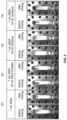
- FIG. 2 shows several digital representations of miscibility experiments performed for methanesulfonic acid in the presence of liquid carbon dioxide (CO 2 ) and a cosolvent.
- FIGS. 3 A- 3 B are schematic diagrams of a composition of an acid-in-CO 2 emulsion for an acid treatment according to the present disclosure.
- FIG. 4 shows example structures for a surfactant for a water-in-CO 2 foam or emulsion for an acid treatment according to the present disclosure.
- FIGS. 5 A- 5 B are schematic diagrams of a composition of a CO 2 -in-acid foam according to the present disclosure.
- This disclosure describes methods and compositions used in stimulating hydrocarbon reservoirs for enhancing hydrocarbon fluid recovery. More specifically, the present disclosure discusses example techniques (e.g., compositions and methods of delivery thereof) for attenuating a reaction rate between an acid and a rock matrix by dispersing or dissolving the acid in a CO 2 phase. In some aspects, by segregating the acid from water, an acid activity is reduced or eliminated until the CO 2 -acid system combines with water in the rock formation or from a pumped fluid.
- example techniques e.g., compositions and methods of delivery thereof
- Example implementations of the present disclosure include the provision of alternative low-viscosity acid systems, which can facilitate ease of pumping of a composition to a desired location in a rock formation with minimal pressure loss due to friction (as opposed to, for example, dispersing acid in diesel to form an emulsion, which has a high viscosity and hence friction when pumping).
- CO 2 can have a high diffusivity and can penetrate deep into the rock formation to extend the depth of stimulation in an acid job.
- hydrochloric acid is the most common acid used to stimulate carbonate formations. This selection is primarily driven by its cost-effectiveness and proven success and efficiency towards dissolving calcium and magnesium-based carbonates. Additionally, the reaction products are readily soluble in water which is advantageous for formation damage prevention.
- HCl hydrochloric acid
- HCl rapidly reacts with the rock matrix, particularly at elevated temperatures, and as a result, large volumes of acid are required to stimulate the pay zone, and deep penetration of the acid is difficult to achieve.
- HOMs methanesulfonic acid
- emulsion form i.e. acid-in-diesel
- quality control concerns as noted.
- Example compositions according to the present disclosure include acid-in-CO 2 compositions formed from a variety of example techniques.
- An example technique can include dissolving an acid in CO 2 directly or assisted by cosolvent(s), surfactant(s), or both.
- Another example technique can include preparing single or double emulsions that include microemulsions, in which case surfactant(s), particles, or both are used to form an acid-in-CO 2 emulsion (e.g., droplets of HCl/water dispersed in a continuous phase of CO 2 that also contains an acid).
- Another example technique can include preparing an acid-based CO 2 foam system, where water is a continuous phase and suitable surfactants are selected to enable stability of the as-prepared foam under reservoir conditions.
- the example techniques can take advantage of the insight that certain compositions are useful for controlled preparation of an acid capable of stimulating carbonate formations at a desirable time and/or location, thus favoring deeper penetration of an acid and/or use of less acid than previous methods.
- the use of CO 2 can take advantage of recent and future developments in direct air capture (DAC) of CO 2 , which may continue to increase over the coming decades, and large quantities of CO 2 will be available for utilization. Injection of supercritical CO 2 into subterranean formations can ultimately lead to some CO 2 trapping and sequestration which is also of benefit.
- DAC direct air capture
- the example techniques also take advantage of the insight that there are a limited number of acids that can be dissolved directly in CO 2 .
- Strong mineral acids are typically highly polar or ionic and dissolve well in water but not in CO 2 such as hydrochloric acid.
- an acid can be dissolved in supercritical CO 2 and used for subterranean rock stimulation.
- the range of acids that could be directly dissolved in CO 2 are expanded by the example techniques of the present disclosure by adding a polar cosolvent.
- the example techniques also rely on innovative methods for delivering these types of CO 2 -acid systems to the formation as described in the present disclosure. Some of these methods include delivering acid segregated from water using surfactants in order to form foams, dispersions. or emulsions.
- FIG. 1 illustrates an example of an acid treatment 10 for a well 12 .
- the well 12 can be associated with a reservoir or formation 14 , for example, an unconventional reservoir in which recovery operations in addition to conventional recovery operations are practiced to recover trapped hydrocarbons.
- unconventional reservoirs include rock formations that include tight carbonates such as calcite, dolomite, and combinations thereof.
- the formation 14 includes an underground formation containing hydrocarbons (for example, oil, gas, or both).
- the well 12 can intersect other suitable types of formations 14 , including reservoirs that are naturally fractured or not naturally fractured in any significant amount.
- the well 12 can include a wellbore 20 , casing 22 and well head 24 .
- the wellbore can be a vertical or deviated bore.
- the casing 22 can be cemented or otherwise suitably secured in the wellbore 12 .
- Perforations 26 can be formed in the casing 22 at the level of the formation 14 to allow oil, gas, and by-products to flow into the well 12 and be produced to the surface 25 .
- Perforations 26 can be formed using shape charges, a perforating gun or otherwise.
- a work string 30 can be disposed in the wellbore 20 .
- the work string 30 can be coiled tubing, sectioned pipe or other suitable tubing.
- a delivery tool 32 can be coupled to an end of the work string 30 .
- Packers 36 can seal an annulus 38 of the wellbore 20 above and below the formation 14 .
- Packers 36 can be mechanical, fluid inflatable or other suitable packers.
- One or more pumps 40 can be coupled to the work string 30 at the surface 25 .
- the pumps 40 pump an acid composition 58 down the work string 30 to perform the acid treatment 10 and generate openings 60 (e.g., a wormhole or multiple wormholes).
- the pumps 40 can include mobile vehicles, equipment such as skids or other suitable structures.
- the instruments 44 can also be provided at the surface 25 .
- the instruments 44 can include an acid control system 46 and an acid treatment simulator 47 .
- the acid control system 46 monitors and controls the acid treatment 10 .
- the acid control system 46 can control the pumps 40 and fluid valves to stop and start the acid treatment 10 as well as to fluidly mix (with valves) multiple fluids that are part of the acid treatment 10 .
- the acid control system 46 communicates with surface and subsurface instruments to monitor and control the acid treatment 10 .
- the surface and subsurface instruments may include surface sensors 48 , down-hole sensors 50 and pump controls 52 .
- the acid treatment 58 generally is comprised of an acid-in-CO 2 composition as previously described.
- the present disclosure contemplates three example acid-in-CO 2 compositions that can be used for the acid treatment 58 for matrix stimulation as well as acid fracturing techniques in formations that contain carbonates such as calcite, dolomite, siderite, or a mix, as well as reservoirs that contain predominantly silicates such as sandstone or clays or may be a mixture of carbonates and silicates.
- the example acid-in-CO 2 compositions can be used for matrix acidizing and acid fracturing well formation to improve injectivity in water injectors or disposal wells and not only with oil and gas production wells to improve the well productivity.
- a first example composition can include dissolving an acid in CO 2 directly or assisted by cosolvent(s), surfactant(s), or both.
- this example composition can be formed by direct dissolution of an acid in CO 2 (e.g., liquid or supercritical phase).
- this example composition can be formed by dissolution of the acid in a cosolvent-modified CO 2 (e.g., liquid or supercritical phase).
- one or more acids can be dissolved directly in liquid or supercritical CO 2 .
- the dissolution mechanism can include hydrogen bonding between acid molecules, as well as Lewis acid-base interactions with the CO 2 .
- Example acids that can be used in this composition example can include acetic acid, which has elevated solubility in supercritical CO 2 (and can also serve as a cosolvent to dissolve other materials in CO 2 ).
- formic acid, trifluoroacetic acid, and propionic acid dissolve directly in supercritical CO 2 .
- 2-hydroxypropanoic acid (lactic acid) and 2-hydroxyhexanoic acid dissolve in supercritical CO 2 .
- some organic acids can be dissolved in CO 2 with the aid of a polar cosolvent.
- stearic acid can dissolve in supercritical CO 2 with the following single or dual cosolvent systems: acetic acid, acetic acid and acetonitrile, ethanol, ethanol and acetonitrile, or methyl acetate.
- p-methylbenzene sulfonic acid can dissolve in supercritical CO 2 directly, but its solubility is enhanced through inclusion of ethyl acetate, ethyl acetate and ethanol, ethanol, or acetone.
- benzoic acid dissolves in supercritical CO 2 with ethanol, ethanol and ethyl acetate, or ethyl acetate as cosolvents.
- hydroxybenzoic acid dissolves in supercritical CO 2 with ethanol as a cosolvent.
- hydrofluoric acid dissolves in supercritical CO 2 with pyridine as a cosolvent.
- methanesulfonic acid (HOMs) dissolves in supercritical CO 2 with various cosolvents.
- FIG. 2 shows images of compositions that consist of HOMs and cosolvent before and after mixing in examples (a)-(d).
- FIG. 2 shows digital representation for each of the miscibility experiments performed for HOMs in the presence of liquid CO 2 (LCO 2 ) and cosolvent(s).
- the image to the left of each example, (a)-(d), represents the appearance upon immediate contact with LCO 2 , while the image to the right is after stirring for a duration of 15 minutes.
- Another example technique can include preparing single or double emulsions (both referred to as an “emulsion”) that include microemulsions, in which case surfactant(s), particles, or both are used to form an acid-in-CO 2 emulsion (e.g., droplets of HCl/water dispersed in a continuous phase of CO 2 that also contains an acid).
- an acid-in-CO 2 emulsion e.g., droplets of HCl/water dispersed in a continuous phase of CO 2 that also contains an acid.
- CO 2 forms an outer continuous phase (optionally containing a CO 2 -soluble acid), while water/acid form an internal phase.
- the composition can be, e.g.
- Other additives such as a scale inhibitor, a corrosion inhibitor, an iron control agent, an antisludging agent, or a fluid loss agent can be included.
- the water can also contain a viscosifier such as polysaccharide (e.g., guar) or a friction reducer.
- FIG. 3 A shows a schematic of an emulsion design, which demonstrates an internal aqueous phase containing acid, an external CO 2 carrier phase, and interfacial surfactant according to an example acid-in-CO 2 composition within a wellbore according to this technique.
- FIG. 3 A shows a composition that is volumetrically >70% CO 2 with an acid #1.
- the acid #1 can be selected from a group containing: HCl, strong mineral acids, HF, sulfonic acids such as methanesulfonic acid, ethanesulfonic acid, p-toluene sulfonic acid, formic acid, lactic acid, acetic acid, propanoic acid, 2-hydroxypropanoic acid (lactic acid), and 2-hydroxyhexanoic acid.
- FIG. 3 B shows a schematic of another emulsion design.
- FIG. 3 B shows a composition that is volumetrically >70% CO 2 with an acid #1 and an acid #2.
- the acid #1 can be selected from a group containing: HCl, strong mineral acids, HF, sulfonic acids such as methanesulfonic acid, ethanesulfonic acid, p-toluene sulfonic acid, formic acid, lactic acid, acetic acid, propanoic acid, 2-hydroxypropanoic acid (lactic acid), and 2-hydroxyhexanoic acid.
- the acid #2 can be selected from a group containing: acetic acid, trifluoroacetic acid, propanoic acid, formic acid, 2-hydroxypropanoic acid (lactic acid), and 2-hydroxyhexanoic acid.
- a surfactant is used, which results in an emulsion with CO 2 as the continuous phase.
- the surfactant can be cationic, anionic, nonionic, or zwitterionic.
- the surfactant to make the water-in-CO 2 emulsion can be fluorinated as in the following examples: ammonium carboxylic acid perfluoroether; C 7 F 15 CH(OSO 3 Na + )C 7 H 15 ; bis(1H,1H,5H-octafluoro-n-pentyl) sodium sulfosuccinate (di-HCF4); sodium 1-oxo-1-[4-(perfluorohexyl)phenyl]hexane-2-sulfonate, FC6-HC4; 1-oxo-1-[4-(perfluorohexyl)phenyl]hexane (Nohead FC6HC4); sodium 1,5bis[(1H,1H,2H,2H-perfluorobutyl)oxy]-1,5-dioxopentane-2-sulfonate (2FG(EO) 2 ); sodium 1,5-bis[(1H, 1H,2H,2H-per
- the surfactant to make the water-in-CO 2 emulsion can be fluorinated by [C 6 F 13 mim][(CF 3 ) 3 S], [C 6 F 13 mim]-[C 6 F 13 S], and [C 5 F 11 mim][C 5 F 11 S], which are shown in FIG. 4 .
- FIG. 4 shows example structures for this surfactant.
- the surfactant to make the water-in-CO 2 foam or emulsion can also be nonfluorinated as in the case of poly(ethylene glycol) 2,6,8-trimethyl-4-nonyl ethers such as octa(ethylene glycol) 2,6,8-trimethyl-4-nonyl ether (5b-C 12 E 8 ).
- the amphiphilic block-copolymer can be fluorinated or non-fluorinated as in the case of F(CF 2 CF 2 ) 3-8 CH 2 CH 2 O(CH 2 CH 2 O) 10-15 H and Poly(ethylene oxide)-b-poly(butylene oxide), respectively.
- solid particles can be used to create the emulsion, whether solely or utilized in conjunction with surfactants.
- the solid particles can include the addition of suitable functional materials such as any insoluble solid material or dispersion capable of stabilizing the acid emulsions.
- the functional frameworks can serve as emulsion stabilizers by preferentially adsorbing at the oil-water interface, which reduces the interfacial tension of the droplets and offers enhanced stability.
- Functional frameworks suitable for use in the present example composition can be less than 20 microns.
- functional frameworks suitable for can be nano-sized, for example less than 1000 nm.
- the functional framework can include clays, surface-modified clay-based materials, zeolites, nanoparticles, and hybrid organic-inorganic materials, or combinations thereof.
- Another example technique can include preparing an acid-based CO 2 foam system, where water is a continuous phase and suitable surfactants are selected to enable stability of the as-prepared foam under reservoir conditions.
- water forms an outer continuous phase (optionally containing an acid), and the acid-in-CO 2 forms an internal phase.
- the composition of the foam can be nominally: volumetrically >50% CO 2 containing an acid #1; volumetrically ⁇ 50% water either with no acid or an acid #2; or volumetrically ⁇ 0.05-5% surfactant and/or amphiphilic block co-polymer.
- Other additives such as scale inhibitor, corrosion inhibitor, iron control agent, antisludging agent, fluid loss agent, and otherwise can be included in the emulsion.
- water can also contain a viscosifier such as polysaccharide (e.g., guar) or a friction reducer.
- a viscosifier such as polysaccharide (e.g., guar) or a friction reducer.
- a crosslinked aqueous fluid can also be used, e.g., guar crosslinked with borate, zirconium, titanium, and other ions.
- FIG. 5 A shows a schematic of a foam design, which demonstrates the internal gas phase, external aqueous phase, and interfacial surfactant according to an example acid-in-CO 2 composition within a wellbore according to this technique.
- FIG. 5 A shows a composition that is volumetrically ⁇ 50% water with no acid.
- the acid #1 (of the internal phase) can be selected from a group containing: acetic acid, trifluoroacetic acid, propanoic acid, formic acid, 2-hydroxypropanoic acid (lactic acid), and 2-hydroxyhexanoic acid.
- FIG. 5 B shows a schematic of another foam design.
- FIG. 5 B shows a composition that is volumetrically ⁇ 50% water with an acid #2.
- the acid #2 can be selected from a group containing: HCl, strong mineral acids, HF, sulfonic acids such as methanesulfonic acid, ethanesulfonic acid, p-toluene sulfonic acid, formic acid, lactic acid, acetic acid, propanoic acid, 2-hydroxypropanoic acid (lactic acid), and 2-hydroxyhexanoic acid.
- the surfactant can be a cationic, anionic, nonionic, or zwitterionic compound.
- the compound can have the following properties, resulting in a foam with an aqueous continuous phase: betaines, sulfated or sulfonated alkoxylates, alkyl quarternary amines, alkoxylated linear alcohols, alkyl sulfonates, alkyl aryl sulfonates, C10-C20 alkyldiphenyl ether sulfonates, and other similar compounds.
- Suitable surfactants include, for example.
- the surfactants can be added in concentrations which range typically from about to about 2 percent of the liquid component by weight (from about 0.5 to about 20 gallons per 1000 gallons of liquid).
- the compositions described in Examples #1-3 can be introduced into a subterranean formation as the acid composition 58 in acid treatment 10 for the well 12 to treat the reservoir or formation 14 in example delivery methods.
- the acid treatment 10 (including acid composition 58 ) can be formed and delivered by the acid control system 46 (with the pumps 40 , work string 30 , and delivery tool 32 , among other components, collectively, the “acid delivery system”).
- the acid treatment 10 can be delivered to the formation 14 so as to delay acid formation for deeper stimulation of oil and gas wells drilled in carbonate and sandstone reservoirs based on the formulation of the acid composition 58 according to Examples #1-3.
- the acid in the acid composition 58 is delivered in a CO 2 -phase, where its activity is reduced or eliminated until it mixes with water in the formation 14 .
- Such delay features can be accomplished with the acid treatment 10 according to the following example delivery techniques.
- a composition of at least one acid and liquid or supercritical carbon dioxide (CO 2 ) can be delivered (e.g., circulated, pumped) to a hydrocarbon reservoir, such as the formation 14 , through the work string 30 .
- the delivered composition can be exposed to water to activate the composition (e.g., bring the water into contact with at least one acid).
- the activated composition can treat a rock formation of the hydrocarbon reservoir.
- the pumps 40 can be controlled to circulate two fluids separately into the work string 30 and allow mixing on a pore scale in the formation 14 .
- a first fluid includes CO 2 (liquid or supercritical) that has been premixed with an acid.
- the second fluid includes (or is) water.
- each system can be pumped separately in the form of separate stages into the work string 30 separated by a spacer (e.g., a neutral fluid, such as water, that prevents mixing of the first and second fluids during pumping).
- a spacer e.g., a neutral fluid, such as water, that prevents mixing of the first and second fluids during pumping.
- the two fluids do not mix in the work string 30 (or wellbore), but the mixing process will happen in the pore spaces of the rock formation 14 .
- Suitable acids for this example delivery technique can include acetic acid, trifluoroacetic acid, propanoic acid, formic acid, 2-hydroxypropanoic acid (lactic acid), and 2-hydroxyhexanoic acid.
- the CO 2 phase with acid also contains a cosolvent.
- Acids suitable for combining with a cosolvent include citric acid, stearic acid, benzoic acid, HF, sulfonic acids such as methanesulfonic acid, ethanesulfonic acid, and p-toluene sulfonic acid.
- Cosolvents suitable for aiding in the dissolution of the acid include alcohols (methanol, ethanol, propanol), esters (ethyl acetate, ethyl lactate), pyridine, acetic acid, acetonitrile, and acetone.
- the water phase also contains HCl or organic acid for better and deeper penetration, including deeper wormholes for matrix acidizing and better surface etching for acid fracturing applications.
- the pumps 40 can be controlled to alternately circulate a CO 2 /acid fluid or a CO 2 /acid/cosolvent fluid.
- a first fluid slug can include CO 2 and an acid which are mixed at the surface (e.g., at the wellbore just prior to delivery) and then pumped into the work string 30 .
- This first fluid slug is followed by a second fluid slug of a conventional acid treatment (i.e., not an acid-in-CO 2 composition) from one of the following: HCl, organic acid, emulsified HCl, emulsified organic acid, chelating agent, gelled acid or crosslinked gelled acid.
- the first stage of pumping the CO 2 with acid is to deliver acid (in an acid-in-CO 2 composition) deep into the formation before it reacts to optimally stimulate the reservoir.
- a preflush can be implemented to reduce the oil concentration around the wellbore 20 and to prepare the formation 14 to receive the acid.
- the preflush can be used to remove organic precipitate, adjust the water salinity, mitigate asphaltene and hydrogen sulfide generation, inhibit iron sulfide precipitation, or a combination thereof.
- the preflush can be composed of CO 2 or CO 2 and solvent.
- the CO 2 , acid, and cosolvent may be sufficient to reduce the oil concentration around the wellbore 20 and clean the precipitates.
- a post-flush can be used to push the treatment deeper into the reservoir, allow acid to spend, and then control the pH of the flowback fluid.
- the CO 2 can be mixed with acid directly and pumped to penetrate deeper into the reservoir and improve the outcome of the stimulation treatment.
- the acid composition 58 can be bullheaded directly through the tubing to the formation through the preformation system. Further, in examples where the work string 30 is coiled tubing, the coiled tubing can be used to place and directly spot the acid composition 58 into the formation.
- diverters can be used.
- mechanical diverters such as ball sealers, packers, plugs, nozzles, or combinations thereof can be used to spot the acid composition 58 in a particular part of formation 14 .
- Chemical diverters such as crosslinked acid systems, gelled acid system, use of solid acids like polylactic acid, or combinations thereof can also be used to place the acid composition 58 in a particular part of formation 14 .
- precursors of the acid composition 58 can be mixed with solid acids to achieve, e.g., deeper acid penetration.
- the precursors can be mixed with degradable balls for acid diversion in heterogeneous formations.
- substantially refers to a majority of, or mostly, as in at least about 50%, 60%, 70%, 80%, 90%, 95%, 96%, 97%, 98%, 99%, 99.5%, 99.9%, 99.99%, or at least about 99.999% or more.
- solvent refers to a substance that is added to a mixture of two or more separate substances that are typically immiscible, in order to make them mixable.
- downhole refers to under the surface of the earth, such as a location within or fluidly connected to a wellbore.
- fluid refers to liquids and gels, unless otherwise indicated.
- subterranean material or “subterranean zone” or (hydrocarbon reservoir” refers to any material under the surface of the earth, including under the surface of the bottom of the ocean.
- a subterranean zone or material can be any section of a wellbore and any section of a subterranean petroleum- or water-producing formation or region in fluid contact with the wellbore. Placing a material in a subterranean zone can include contacting the material with any section of a wellbore or with any subterranean region in fluid contact with the material.
- Subterranean materials can include any materials placed into the wellbore such as cement, drill shafts, liners, tubing, casing, or screens; placing a material in a subterranean zone can include contacting with such subterranean materials.
- a subterranean zone or material can be any downhole region that can produce liquid or gaseous petroleum materials, water, or any downhole section in fluid contact with liquid or gaseous petroleum materials, or water.
- a subterranean zone or material can be at least one of an area desired to be fractured, a fracture or an area surrounding a fracture, and a flow pathway or an area surrounding a flow pathway, in which a fracture or a flow pathway can be optionally fluidly connected to a subterranean petroleum- or water-producing region, directly or through one or more fractures or flow pathways.
- treatment of a subterranean zone can include any activity directed to extraction of water or petroleum materials from a subterranean petroleum- or water-producing formation or region, for example, including drilling, stimulation, hydraulic fracturing, clean-up, acidizing, completion, cementing, remedial treatment, abandonment, aquifer remediation, identifying oil rich regions via imaging techniques, and the like.
Landscapes
- Life Sciences & Earth Sciences (AREA)
- Engineering & Computer Science (AREA)
- Mining & Mineral Resources (AREA)
- Geology (AREA)
- Chemical & Material Sciences (AREA)
- General Life Sciences & Earth Sciences (AREA)
- Geochemistry & Mineralogy (AREA)
- Fluid Mechanics (AREA)
- Physics & Mathematics (AREA)
- Environmental & Geological Engineering (AREA)
- Chemical Kinetics & Catalysis (AREA)
- Materials Engineering (AREA)
- Organic Chemistry (AREA)
- General Chemical & Material Sciences (AREA)
- Oil, Petroleum & Natural Gas (AREA)
- Organic Low-Molecular-Weight Compounds And Preparation Thereof (AREA)
Abstract
Description
| Unit of Measure | Full form | ||
| cm | centimeter | ||
| mL | milliliter | ||
| mmol | millimole | ||
| psi | pounds per square inch | ||
| ° C. | degrees Celsius | ||
Claims (21)
Priority Applications (2)
| Application Number | Priority Date | Filing Date | Title |
|---|---|---|---|
| US17/829,972 US11905804B2 (en) | 2022-06-01 | 2022-06-01 | Stimulating hydrocarbon reservoirs |
| US18/416,517 US12276185B2 (en) | 2022-06-01 | 2024-01-18 | Stimulating hydrocarbon reservoirs |
Applications Claiming Priority (1)
| Application Number | Priority Date | Filing Date | Title |
|---|---|---|---|
| US17/829,972 US11905804B2 (en) | 2022-06-01 | 2022-06-01 | Stimulating hydrocarbon reservoirs |
Related Child Applications (1)
| Application Number | Title | Priority Date | Filing Date |
|---|---|---|---|
| US18/416,517 Division US12276185B2 (en) | 2022-06-01 | 2024-01-18 | Stimulating hydrocarbon reservoirs |
Publications (2)
| Publication Number | Publication Date |
|---|---|
| US20230392484A1 US20230392484A1 (en) | 2023-12-07 |
| US11905804B2 true US11905804B2 (en) | 2024-02-20 |
Family
ID=88977288
Family Applications (2)
| Application Number | Title | Priority Date | Filing Date |
|---|---|---|---|
| US17/829,972 Active US11905804B2 (en) | 2022-06-01 | 2022-06-01 | Stimulating hydrocarbon reservoirs |
| US18/416,517 Active US12276185B2 (en) | 2022-06-01 | 2024-01-18 | Stimulating hydrocarbon reservoirs |
Family Applications After (1)
| Application Number | Title | Priority Date | Filing Date |
|---|---|---|---|
| US18/416,517 Active US12276185B2 (en) | 2022-06-01 | 2024-01-18 | Stimulating hydrocarbon reservoirs |
Country Status (1)
| Country | Link |
|---|---|
| US (2) | US11905804B2 (en) |
Cited By (1)
| Publication number | Priority date | Publication date | Assignee | Title |
|---|---|---|---|---|
| US20240200430A1 (en) * | 2022-06-01 | 2024-06-20 | Saudi Arabian Oil Company | Stimulating hydrocarbon reservoirs |
Citations (119)
| Publication number | Priority date | Publication date | Assignee | Title |
|---|---|---|---|---|
| US701154A (en) | 1902-03-13 | 1902-05-27 | Arthur Cole | Necktie-frame. |
| US3456183A (en) | 1957-07-30 | 1969-07-15 | Schlumberger Technology Corp | Detection of oil by nuclear magnetic resonance |
| US3616855A (en) | 1970-07-23 | 1971-11-02 | New Mexico Tech Res Found | Method of bulking or caving a volume of subsurface material |
| US3912330A (en) | 1974-03-04 | 1975-10-14 | Us Interior | Chemical mining of copper porphyry ores |
| US4043599A (en) | 1975-10-17 | 1977-08-23 | Kennecott Copper Corporation | Acid preinjection to decrease instantaneous acid consumption in in-situ mining |
| US4108965A (en) | 1976-10-15 | 1978-08-22 | Rockwell International Corporation | (NF4)2 NiF6 High energy solid propellant oxidizer and method of producing the same |
| EP0247669A2 (en) | 1986-05-29 | 1987-12-02 | Shell Internationale Researchmaatschappij B.V. | Method for analyzing thinly bedded sand/shale formations |
| US5031700A (en) | 1990-06-15 | 1991-07-16 | Exxon Chemical Patents Inc. | Method of improving formation permeability using chlorine dioxide |
| US5199490A (en) | 1991-11-18 | 1993-04-06 | Texaco Inc. | Formation treating |
| WO1997028098A1 (en) | 1996-02-02 | 1997-08-07 | Portlandzementwerk Dotternhausen Rudolf Rohrbach Kommanditgesellschaft | Binding agent mixture for the preparation of mineral slag-sand free material for retention wall and a process for preparation of this binding agent mixture |
| US5944104A (en) | 1996-01-31 | 1999-08-31 | Vastar Resources, Inc. | Chemically induced stimulation of subterranean carbonaceous formations with gaseous oxidants |
| US5967233A (en) | 1996-01-31 | 1999-10-19 | Vastar Resources, Inc. | Chemically induced stimulation of subterranean carbonaceous formations with aqueous oxidizing solutions |
| US6076046A (en) | 1998-07-24 | 2000-06-13 | Schlumberger Technology Corporation | Post-closure analysis in hydraulic fracturing |
| WO2000060379A1 (en) | 1999-04-02 | 2000-10-12 | Conoco, Inc. | A method for gravity and magnetic data inversion using vector and tensor data with seismic imaging and geopressure prediction for oil, gas and mineral exploration and production |
| US6131661A (en) | 1998-08-03 | 2000-10-17 | Tetra Technologies Inc. | Method for removing filtercake |
| WO2001094749A1 (en) | 2000-06-06 | 2001-12-13 | Halliburton Energy Services, Inc. | Real-time method for maintaining formation stability |
| US20020003115A1 (en) | 1997-02-27 | 2002-01-10 | Conaway Lawrence M. | Method and apparatus for separating hydrocarbons from mineral substrates |
| WO2002064702A1 (en) | 2001-02-09 | 2002-08-22 | Stierli + Ruggli | Binder and method for the production of a soil stabilizing binder and soils, walls or parting layers stabilized using said binder or method |
| WO2004005435A1 (en) | 2002-07-08 | 2004-01-15 | Conocophillips Company | Improved hydrocarbon desulfurization with pre-oxidation of organosulfur compounds |
| US6705398B2 (en) | 2001-08-03 | 2004-03-16 | Schlumberger Technology Corporation | Fracture closure pressure determination |
| US6715553B2 (en) | 2002-05-31 | 2004-04-06 | Halliburton Energy Services, Inc. | Methods of generating gas in well fluids |
| US20040101457A1 (en) | 2002-06-11 | 2004-05-27 | Pahlman John E. | Disassociation processing of metal oxides |
| US20050039919A1 (en) | 2003-08-19 | 2005-02-24 | Harris Phillip C. | Methods of fracturing high temperature subterranean zones and foamed fracturing fluids therefor |
| US20050059558A1 (en) | 2003-06-27 | 2005-03-17 | Blauch Matthew E. | Methods for improving proppant pack permeability and fracture conductivity in a subterranean well |
| CN1621803A (en) | 2004-12-23 | 2005-06-01 | 喻勇 | Method for testing tensile strength of fragile material |
| US7007752B2 (en) | 2003-03-21 | 2006-03-07 | Halliburton Energy Services, Inc. | Well treatment fluid and methods with oxidized polysaccharide-based polymers |
| US7011154B2 (en) | 2000-04-24 | 2006-03-14 | Shell Oil Company | In situ recovery from a kerogen and liquid hydrocarbon containing formation |
| US7077199B2 (en) | 2001-10-24 | 2006-07-18 | Shell Oil Company | In situ thermal processing of an oil reservoir formation |
| US7148184B2 (en) | 2003-07-22 | 2006-12-12 | Schlumberger Technology Corporation | Self-diverting foamed system |
| US20070137858A1 (en) | 2005-12-20 | 2007-06-21 | Considine Brian C | Method for extraction of hydrocarbon fuels or contaminants using electrical energy and critical fluids |
| US20070235181A1 (en) | 2003-09-16 | 2007-10-11 | Commonwealth Scientific And Industrial Reseach Organisation | Hydraulic Fracturing |
| US7291651B2 (en) | 2003-12-05 | 2007-11-06 | Schlumberger Technology Corporation | Carbon dioxide foamed fluids |
| WO2008001218A2 (en) | 2006-06-28 | 2008-01-03 | Osat, Llc | Method for releasing organics from shale and like materials to produce a liquid shale fuel |
| US20080006410A1 (en) | 2006-02-16 | 2008-01-10 | Looney Mark D | Kerogen Extraction From Subterranean Oil Shale Resources |
| US20080217012A1 (en) | 2007-03-08 | 2008-09-11 | Bj Services Company | Gelled emulsions and methods of using the same |
| CA2635868A1 (en) | 2007-06-28 | 2008-12-28 | Schlumberger Canada Limited | Oxidative internal breaker system with breaking activators for viscoelastic surfactant fluids |
| US20090032252A1 (en) | 2007-07-30 | 2009-02-05 | Boney Curtis L | Degradable cement compositions containing degrading materials and methods of cementing in wellbores |
| US20090044945A1 (en) | 2006-01-27 | 2009-02-19 | Schlumberger Technology Corporation | Method for hydraulic fracturing of subterranean formation |
| US7513306B2 (en) | 2003-07-22 | 2009-04-07 | Precision Combustion, Inc. | Method for natural gas production |
| US20090145607A1 (en) | 2007-12-07 | 2009-06-11 | Leiming Li | High Temperature Fracturing Fluids and Method of Use |
| US20090203557A1 (en) | 2008-02-07 | 2009-08-13 | Barnes Julian Richard | Method and composition for enhanced hydrocarbons recovery |
| US7642223B2 (en) | 2004-10-18 | 2010-01-05 | Halliburton Energy Services, Inc. | Methods of generating a gas in a plugging composition to improve its sealing ability in a downhole permeable zone |
| US20100044049A1 (en) | 2008-07-25 | 2010-02-25 | Century Oilfield Services Inc. | Green coal bed methane fracturing fluid compositions, methods of preparation and methods of use |
| US20100126936A1 (en) | 2008-11-24 | 2010-05-27 | Arkansas Reclamation Co., Llc | Process and facility for treating waste drilling mud |
| CN101819111A (en) | 2010-03-30 | 2010-09-01 | 中南大学 | Method for testing tensile modulus of brittle material |
| US20100243248A1 (en) | 2006-12-01 | 2010-09-30 | Golomb Dan S | Particle Stabilized Emulsions for Enhanced Hydrocarbon Recovery |
| WO2010138914A1 (en) | 2009-05-29 | 2010-12-02 | Oxonica Materials Inc. | Sers-active particles or substances and uses thereof |
| US20100323933A1 (en) | 2009-06-23 | 2010-12-23 | Fuller Michael J | Hydrocarbon-Based Filtercake Dissolution Fluid |
| US20110005969A1 (en) | 2009-07-09 | 2011-01-13 | Giffin Wade J | Compositions and processes for fracturing subterranean formations |
| US7878248B2 (en) | 2008-12-29 | 2011-02-01 | Schlumberger Technology Corporation | System, method, and apparatus for post-fracture treatment |
| WO2011035294A2 (en) | 2009-09-21 | 2011-03-24 | University Of Georgia Research Foundation, Inc. | Near infrared doped phosphors having an alkaline gallate matrix |
| WO2011035292A2 (en) | 2009-09-21 | 2011-03-24 | University Of Georgia Research Foundation, Inc. | Near infrared doped phosphors having a zinc, germanium, gallate matrix |
| CN102183410A (en) | 2011-01-27 | 2011-09-14 | 中国科学院武汉岩土力学研究所 | Brazilian split method for measuring elastic parameter of rock under extension condition |
| US8146416B2 (en) | 2009-02-13 | 2012-04-03 | Schlumberger Technology Corporation | Methods and apparatus to perform stress testing of geological formations |
| WO2012051647A1 (en) | 2010-10-18 | 2012-04-26 | Curtin University Of Technology | An apparatus for and a method of characterising mechanical properties of a sample |
| WO2012057910A2 (en) | 2010-10-27 | 2012-05-03 | Exxonmobil Upstream Research Company | Methods of using nano-particles in wellbore operations |
| WO2012087887A2 (en) | 2010-12-22 | 2012-06-28 | Schlumberger Canada Limited | Sulfate molecule removal through inorganic or divalent ion nuclei seeding |
| WO2012088476A2 (en) | 2010-12-22 | 2012-06-28 | Chevron U.S.A. Inc. | In-situ kerogen conversion and recovery |
| WO2012087898A2 (en) | 2010-12-21 | 2012-06-28 | Schlumberger Canada Limited | Wettability analysis of disaggregated material |
| WO2012104582A1 (en) | 2011-01-31 | 2012-08-09 | Halliburton Energy Services Inc. | Increasing fracture complexity in ultra-low permeable subterranean formation using degradable particulate |
| WO2012122505A2 (en) | 2011-03-09 | 2012-09-13 | Schlumberger Canada Limited | Cross-linkers for hydraulic fracturing fluid |
| WO2012171857A1 (en) | 2011-06-13 | 2012-12-20 | Akzo Nobel Chemicals International B.V. | Treatment of shale formations using a chelating agent |
| WO2013052359A1 (en) | 2011-10-03 | 2013-04-11 | The Board Of Regents Of The University Of Oklahoma | Method and foam composition for recovering hydrocarbons from a subterranean reservoir |
| US20130161008A1 (en) | 2011-12-22 | 2013-06-27 | Argonne National Laboratory | Preparation and use of nano-catalysts for in-situ reaction with kerogen |
| WO2013112114A1 (en) | 2011-10-03 | 2013-08-01 | Landmark Graphics Corporation | Enhanced 1-d method for prediction of mud weight window for subsalt well sections |
| WO2013149122A1 (en) | 2012-03-29 | 2013-10-03 | Schlumberger Canada Limited | Additive for subterranean treatment |
| WO2013155061A1 (en) | 2012-04-09 | 2013-10-17 | M-I L.L.C. | Triggered heating of wellbore fluids by carbon nanomaterials |
| CN103387827A (en) | 2012-05-09 | 2013-11-13 | 中国石油化工股份有限公司 | Nano-material associated clean fracturing fluid system and application thereof in oil and gas fields |
| US20130306321A1 (en) | 2012-05-17 | 2013-11-21 | Camille LANCTOT-DOWNS | Liquefied industrial gas based solution in hydraulic fracturing |
| US20130341028A1 (en) | 2010-06-28 | 2013-12-26 | Baker Hughes Incorporated | Controllably tuning properties of a fluid using modified nanoparticles |
| US8616294B2 (en) | 2007-05-20 | 2013-12-31 | Pioneer Energy, Inc. | Systems and methods for generating in-situ carbon dioxide driver gas for use in enhanced oil recovery |
| WO2014008598A1 (en) | 2012-07-13 | 2014-01-16 | Nfluids Inc. | Drilling fluids with nano and granular particles and their use for wellbore strengthening |
| WO2014123672A1 (en) | 2013-02-05 | 2014-08-14 | Board Of Regents, The University Of Texas System | Hydrophobic paramagnetic nanoparticles as intelligent crude oil tracers |
| US8899331B2 (en) | 2008-10-02 | 2014-12-02 | American Shale Oil, Llc | Carbon sequestration in depleted oil shale deposits |
| US20150041136A1 (en) | 2013-08-10 | 2015-02-12 | Truox, Inc. | Method for the in-situ generation chlorine dioxide |
| US20150068749A1 (en) | 2012-10-09 | 2015-03-12 | Eric John Wernimont | Method, Apparatus and Composition for Increased Recovery of Hydrocarbons by Paraffin and Asphaltene Control from Reaction of Fuels and Selective Oxidizers in the Subterranean Environment |
| US20150083405A1 (en) | 2013-09-25 | 2015-03-26 | Shell Oil Company | Method of conducting diagnostics on a subterranean formation |
| US20150083420A1 (en) | 2013-09-26 | 2015-03-26 | Baker Hughes Incorporated | Method for optimizing conductivity in a hydraulic fracturing operation |
| WO2015041664A1 (en) | 2013-09-20 | 2015-03-26 | Halliburton Energy Services, Inc. | Adjusting surfactant concentrations during hydraulic fracturing |
| US9033033B2 (en) | 2010-12-21 | 2015-05-19 | Chevron U.S.A. Inc. | Electrokinetic enhanced hydrocarbon recovery from oil shale |
| WO2015097116A1 (en) | 2013-12-23 | 2015-07-02 | Institutt For Energiteknikk | Particulate tracer materials |
| WO2015126082A1 (en) | 2014-02-24 | 2015-08-27 | 삼성정밀화학 주식회사 | Electrolyte for lithium secondary battery and lithium secondary battery comprising same |
| US20150300140A1 (en) | 2013-08-27 | 2015-10-22 | Halliburton Energy Services, Inc. | Acid diversion treatments in injection wells using permeability modifiers |
| WO2015163858A1 (en) | 2014-04-22 | 2015-10-29 | Landmark Graphics Corporation | Integrated 3d method for prediction of mud weight window for complex well sections |
| WO2015181028A1 (en) | 2014-05-27 | 2015-12-03 | Statoil Gulf Services LLC | Applications of ultra-low viscosity fluids to stimulate ultra-tight hydrocarbon-bearing formations |
| WO2015200060A2 (en) | 2014-06-23 | 2015-12-30 | The Charles Stark Draper Laboratory, Inc. | Injection well identification using tracer particles |
| US20160017202A1 (en) | 2014-07-21 | 2016-01-21 | Baker Hughes Incorporated | Electrically conductive oil-based fluids |
| US20160024370A1 (en) * | 2014-07-22 | 2016-01-28 | King Fahd University Of Petroleum And Minerals | Zero-invasion acidic drilling fluid |
| US20160061017A1 (en) | 2013-09-20 | 2016-03-03 | Hakkiburton Energy Services, Inc. | Methods for Enhancing and Maintaining Fracture Conductivity after Fracturing Shale Formations without Proppant Placement |
| CN105445440A (en) | 2015-11-19 | 2016-03-30 | 西南石油大学 | Method for evaluating fracturing property of shale based on rock debris microscopic characteristics |
| CN105567213A (en) | 2016-03-04 | 2016-05-11 | 成都佰椿石油科技有限公司 | High temperature-resisting cleaning CO2 foam fracturing liquid suitable for unconventional oil and gas reservoir development |
| WO2016094153A2 (en) | 2014-12-10 | 2016-06-16 | Bp Corporation North America Inc. | Estimation of conductivity for nanoporous materials |
| US20160177674A1 (en) | 2013-08-27 | 2016-06-23 | Halliburton Energy Services, Inc. | Simulating Fluid Leak-Off and Flow-Back in a Fractured Subterranean Region |
| US20170051599A1 (en) * | 2013-06-26 | 2017-02-23 | Baker Hughes Incorporated | Method of Enhancing Fracture Complexity Using Far-Field Divert Systems |
| US20170051598A1 (en) | 2015-08-20 | 2017-02-23 | FracGeo, LLC | System For Hydraulic Fracturing Design And Optimization In Naturally Fractured Reservoirs |
| WO2017035371A1 (en) | 2015-08-25 | 2017-03-02 | Conocophillips Company | Method for estimating stress magnitude |
| WO2017040824A1 (en) | 2015-09-03 | 2017-03-09 | Saudi Arabian Oil Company | Treatment of kerogen in subterranean formations |
| WO2017040834A1 (en) | 2015-09-03 | 2017-03-09 | Saudi Arabian Oil Company | Nano-level evaluation of kerogen-rich reservoir rock |
| US9644137B2 (en) | 2014-02-04 | 2017-05-09 | Conocophillips Company | Method of cryogenic acid fracking |
| US20170145793A1 (en) | 2015-08-20 | 2017-05-25 | FracGeo, LLC | Method For Modeling Stimulated Reservoir Properties Resulting From Hydraulic Fracturing In Naturally Fractured Reservoirs |
| WO2017086975A1 (en) | 2015-11-19 | 2017-05-26 | Halliburton Energy Services, Inc. | Stimulated fracture network partitioning from microseismicity analysis |
| WO2017136641A1 (en) | 2016-02-05 | 2017-08-10 | Gtrack Technologies, Inc. | Mesoporous silica nanoparticles as fluorescent tracers for reservoir characterization |
| US20170247997A1 (en) | 2014-08-20 | 2017-08-31 | Schlumberger Technology Corporation | A method of treating a subterranean formation |
| US20170328179A1 (en) | 2014-12-31 | 2017-11-16 | Halliburton Energy Services, Inc. | Hydraulic Fracturing Apparatus, Methods, and Systems |
| WO2018025010A1 (en) | 2016-08-05 | 2018-02-08 | Independence Oilfield Chemicals Llc | Formulations comprising recovered water and a viscosifier, and associated methods |
| WO2018045290A1 (en) | 2016-09-01 | 2018-03-08 | Hull Katherine Leigh | Treatment of sulfide scales |
| US20180305208A1 (en) | 2011-03-22 | 2018-10-25 | Sabre Intellectual Property Holdings Llc | Chlorine dioxide precursor and methods of using same |
| US20180327658A1 (en) * | 2015-04-14 | 2018-11-15 | Saudi Arabian Oil Company | Supercritical Carbon Dioxide Emulsified Acid |
| US20180355707A1 (en) | 2015-09-03 | 2018-12-13 | Schlumberger Technology Corporation | Method of integrating fracture, production, and reservoir operations into geomechanical operations of a wellsite |
| US20190010795A1 (en) | 2017-07-10 | 2019-01-10 | Mauro Lo Cascio | Methods for Deep Reservoir Stimulation Using Acid-Forming Fluids |
| US20190078424A1 (en) | 2015-11-19 | 2019-03-14 | Halliburton Energy Services, Inc. | Fracture network fluid flow simulation with systematic fracture orientation |
| WO2019140058A1 (en) | 2018-01-10 | 2019-07-18 | Saudi Arabian Oil Company | Treatment of kerogen in subterranean zones |
| US20190292436A1 (en) | 2015-12-18 | 2019-09-26 | Sabre Intellectual Property Holdings Llc | Chlorine Dioxide Containing Mixtures And Chlorine Dioxide Bulk Treatments For Enhancing Oil And Gas Recovery |
| US10472555B2 (en) | 2016-04-08 | 2019-11-12 | Schlumberger Technology Corporation | Polymer gel for water control applications |
| US20210024814A1 (en) | 2019-07-24 | 2021-01-28 | Saudi Arabian Oil Company | Oxidizers for carbon dioxide-based fracturing fluids |
| US20210024808A1 (en) | 2019-07-24 | 2021-01-28 | Saudi Arabian Oil Company | Oxidizing gasses for carbon dioxide-based fracturing fluids |
| US20210198559A1 (en) | 2019-12-31 | 2021-07-01 | Saudi Arabian Oil Company | Viscoelastic-Surfactant Fracturing Fluids Having Oxidizer |
| US20210198558A1 (en) | 2019-12-31 | 2021-07-01 | Saudi Arabian Oil Company | Reactive Hydraulic Fracturing Fluid |
| US20210246363A1 (en) * | 2020-02-07 | 2021-08-12 | King Fahd University Of Petroleum And Minerals | Method of improving rock hardness in carbonate formations |
Family Cites Families (2)
| Publication number | Priority date | Publication date | Assignee | Title |
|---|---|---|---|---|
| CN102224186B (en) * | 2008-10-15 | 2013-05-15 | 陶氏环球技术有限责任公司 | Compositions for oil recovery and methods of their use |
| US11905804B2 (en) | 2022-06-01 | 2024-02-20 | Saudi Arabian Oil Company | Stimulating hydrocarbon reservoirs |
-
2022
- 2022-06-01 US US17/829,972 patent/US11905804B2/en active Active
-
2024
- 2024-01-18 US US18/416,517 patent/US12276185B2/en active Active
Patent Citations (129)
| Publication number | Priority date | Publication date | Assignee | Title |
|---|---|---|---|---|
| US701154A (en) | 1902-03-13 | 1902-05-27 | Arthur Cole | Necktie-frame. |
| US3456183A (en) | 1957-07-30 | 1969-07-15 | Schlumberger Technology Corp | Detection of oil by nuclear magnetic resonance |
| US3616855A (en) | 1970-07-23 | 1971-11-02 | New Mexico Tech Res Found | Method of bulking or caving a volume of subsurface material |
| US3912330A (en) | 1974-03-04 | 1975-10-14 | Us Interior | Chemical mining of copper porphyry ores |
| US4043599A (en) | 1975-10-17 | 1977-08-23 | Kennecott Copper Corporation | Acid preinjection to decrease instantaneous acid consumption in in-situ mining |
| US4108965A (en) | 1976-10-15 | 1978-08-22 | Rockwell International Corporation | (NF4)2 NiF6 High energy solid propellant oxidizer and method of producing the same |
| EP0247669A2 (en) | 1986-05-29 | 1987-12-02 | Shell Internationale Researchmaatschappij B.V. | Method for analyzing thinly bedded sand/shale formations |
| US5031700A (en) | 1990-06-15 | 1991-07-16 | Exxon Chemical Patents Inc. | Method of improving formation permeability using chlorine dioxide |
| US5199490A (en) | 1991-11-18 | 1993-04-06 | Texaco Inc. | Formation treating |
| US5944104A (en) | 1996-01-31 | 1999-08-31 | Vastar Resources, Inc. | Chemically induced stimulation of subterranean carbonaceous formations with gaseous oxidants |
| US5967233A (en) | 1996-01-31 | 1999-10-19 | Vastar Resources, Inc. | Chemically induced stimulation of subterranean carbonaceous formations with aqueous oxidizing solutions |
| WO1997028098A1 (en) | 1996-02-02 | 1997-08-07 | Portlandzementwerk Dotternhausen Rudolf Rohrbach Kommanditgesellschaft | Binding agent mixture for the preparation of mineral slag-sand free material for retention wall and a process for preparation of this binding agent mixture |
| US20020003115A1 (en) | 1997-02-27 | 2002-01-10 | Conaway Lawrence M. | Method and apparatus for separating hydrocarbons from mineral substrates |
| US6076046A (en) | 1998-07-24 | 2000-06-13 | Schlumberger Technology Corporation | Post-closure analysis in hydraulic fracturing |
| US6131661A (en) | 1998-08-03 | 2000-10-17 | Tetra Technologies Inc. | Method for removing filtercake |
| US6143698A (en) | 1998-08-03 | 2000-11-07 | Tetra Technologies, Inc. | Method for removing filtercake |
| WO2000060379A1 (en) | 1999-04-02 | 2000-10-12 | Conoco, Inc. | A method for gravity and magnetic data inversion using vector and tensor data with seismic imaging and geopressure prediction for oil, gas and mineral exploration and production |
| US7011154B2 (en) | 2000-04-24 | 2006-03-14 | Shell Oil Company | In situ recovery from a kerogen and liquid hydrocarbon containing formation |
| WO2001094749A1 (en) | 2000-06-06 | 2001-12-13 | Halliburton Energy Services, Inc. | Real-time method for maintaining formation stability |
| WO2002064702A1 (en) | 2001-02-09 | 2002-08-22 | Stierli + Ruggli | Binder and method for the production of a soil stabilizing binder and soils, walls or parting layers stabilized using said binder or method |
| US6705398B2 (en) | 2001-08-03 | 2004-03-16 | Schlumberger Technology Corporation | Fracture closure pressure determination |
| US7077199B2 (en) | 2001-10-24 | 2006-07-18 | Shell Oil Company | In situ thermal processing of an oil reservoir formation |
| US6715553B2 (en) | 2002-05-31 | 2004-04-06 | Halliburton Energy Services, Inc. | Methods of generating gas in well fluids |
| US20040101457A1 (en) | 2002-06-11 | 2004-05-27 | Pahlman John E. | Disassociation processing of metal oxides |
| WO2004005435A1 (en) | 2002-07-08 | 2004-01-15 | Conocophillips Company | Improved hydrocarbon desulfurization with pre-oxidation of organosulfur compounds |
| US7007752B2 (en) | 2003-03-21 | 2006-03-07 | Halliburton Energy Services, Inc. | Well treatment fluid and methods with oxidized polysaccharide-based polymers |
| US20050059558A1 (en) | 2003-06-27 | 2005-03-17 | Blauch Matthew E. | Methods for improving proppant pack permeability and fracture conductivity in a subterranean well |
| US7148184B2 (en) | 2003-07-22 | 2006-12-12 | Schlumberger Technology Corporation | Self-diverting foamed system |
| US7513306B2 (en) | 2003-07-22 | 2009-04-07 | Precision Combustion, Inc. | Method for natural gas production |
| US20050039919A1 (en) | 2003-08-19 | 2005-02-24 | Harris Phillip C. | Methods of fracturing high temperature subterranean zones and foamed fracturing fluids therefor |
| US20070235181A1 (en) | 2003-09-16 | 2007-10-11 | Commonwealth Scientific And Industrial Reseach Organisation | Hydraulic Fracturing |
| US7291651B2 (en) | 2003-12-05 | 2007-11-06 | Schlumberger Technology Corporation | Carbon dioxide foamed fluids |
| US7642223B2 (en) | 2004-10-18 | 2010-01-05 | Halliburton Energy Services, Inc. | Methods of generating a gas in a plugging composition to improve its sealing ability in a downhole permeable zone |
| CN1621803A (en) | 2004-12-23 | 2005-06-01 | 喻勇 | Method for testing tensile strength of fragile material |
| US20070137858A1 (en) | 2005-12-20 | 2007-06-21 | Considine Brian C | Method for extraction of hydrocarbon fuels or contaminants using electrical energy and critical fluids |
| US20090044945A1 (en) | 2006-01-27 | 2009-02-19 | Schlumberger Technology Corporation | Method for hydraulic fracturing of subterranean formation |
| US20080006410A1 (en) | 2006-02-16 | 2008-01-10 | Looney Mark D | Kerogen Extraction From Subterranean Oil Shale Resources |
| WO2008001218A2 (en) | 2006-06-28 | 2008-01-03 | Osat, Llc | Method for releasing organics from shale and like materials to produce a liquid shale fuel |
| US20100243248A1 (en) | 2006-12-01 | 2010-09-30 | Golomb Dan S | Particle Stabilized Emulsions for Enhanced Hydrocarbon Recovery |
| US20080217012A1 (en) | 2007-03-08 | 2008-09-11 | Bj Services Company | Gelled emulsions and methods of using the same |
| US8616294B2 (en) | 2007-05-20 | 2013-12-31 | Pioneer Energy, Inc. | Systems and methods for generating in-situ carbon dioxide driver gas for use in enhanced oil recovery |
| CA2635868A1 (en) | 2007-06-28 | 2008-12-28 | Schlumberger Canada Limited | Oxidative internal breaker system with breaking activators for viscoelastic surfactant fluids |
| US20090032252A1 (en) | 2007-07-30 | 2009-02-05 | Boney Curtis L | Degradable cement compositions containing degrading materials and methods of cementing in wellbores |
| US20090145607A1 (en) | 2007-12-07 | 2009-06-11 | Leiming Li | High Temperature Fracturing Fluids and Method of Use |
| US20090203557A1 (en) | 2008-02-07 | 2009-08-13 | Barnes Julian Richard | Method and composition for enhanced hydrocarbons recovery |
| US20100044049A1 (en) | 2008-07-25 | 2010-02-25 | Century Oilfield Services Inc. | Green coal bed methane fracturing fluid compositions, methods of preparation and methods of use |
| US8899331B2 (en) | 2008-10-02 | 2014-12-02 | American Shale Oil, Llc | Carbon sequestration in depleted oil shale deposits |
| US20100126936A1 (en) | 2008-11-24 | 2010-05-27 | Arkansas Reclamation Co., Llc | Process and facility for treating waste drilling mud |
| US7878248B2 (en) | 2008-12-29 | 2011-02-01 | Schlumberger Technology Corporation | System, method, and apparatus for post-fracture treatment |
| US8146416B2 (en) | 2009-02-13 | 2012-04-03 | Schlumberger Technology Corporation | Methods and apparatus to perform stress testing of geological formations |
| WO2010138914A1 (en) | 2009-05-29 | 2010-12-02 | Oxonica Materials Inc. | Sers-active particles or substances and uses thereof |
| US20100323933A1 (en) | 2009-06-23 | 2010-12-23 | Fuller Michael J | Hydrocarbon-Based Filtercake Dissolution Fluid |
| US20110005969A1 (en) | 2009-07-09 | 2011-01-13 | Giffin Wade J | Compositions and processes for fracturing subterranean formations |
| WO2011035292A2 (en) | 2009-09-21 | 2011-03-24 | University Of Georgia Research Foundation, Inc. | Near infrared doped phosphors having a zinc, germanium, gallate matrix |
| WO2011035294A2 (en) | 2009-09-21 | 2011-03-24 | University Of Georgia Research Foundation, Inc. | Near infrared doped phosphors having an alkaline gallate matrix |
| EP2480626A2 (en) | 2009-09-21 | 2012-08-01 | The University Of Georgia Research Foundation, Inc | Near infrared doped phosphors having an alkaline gallate matrix |
| EP2480625A2 (en) | 2009-09-21 | 2012-08-01 | The University Of Georgia Research Foundation, Inc | Near infrared doped phosphors having a zinc, germanium, gallate matrix |
| CN101819111A (en) | 2010-03-30 | 2010-09-01 | 中南大学 | Method for testing tensile modulus of brittle material |
| US20130341028A1 (en) | 2010-06-28 | 2013-12-26 | Baker Hughes Incorporated | Controllably tuning properties of a fluid using modified nanoparticles |
| WO2012051647A1 (en) | 2010-10-18 | 2012-04-26 | Curtin University Of Technology | An apparatus for and a method of characterising mechanical properties of a sample |
| WO2012057910A2 (en) | 2010-10-27 | 2012-05-03 | Exxonmobil Upstream Research Company | Methods of using nano-particles in wellbore operations |
| WO2012087898A2 (en) | 2010-12-21 | 2012-06-28 | Schlumberger Canada Limited | Wettability analysis of disaggregated material |
| US9033033B2 (en) | 2010-12-21 | 2015-05-19 | Chevron U.S.A. Inc. | Electrokinetic enhanced hydrocarbon recovery from oil shale |
| WO2012088476A2 (en) | 2010-12-22 | 2012-06-28 | Chevron U.S.A. Inc. | In-situ kerogen conversion and recovery |
| US20120160486A1 (en) | 2010-12-22 | 2012-06-28 | Chevron U.S.A. Inc. | In-situ kerogen conversion and recovery |
| WO2012087887A2 (en) | 2010-12-22 | 2012-06-28 | Schlumberger Canada Limited | Sulfate molecule removal through inorganic or divalent ion nuclei seeding |
| CN102183410A (en) | 2011-01-27 | 2011-09-14 | 中国科学院武汉岩土力学研究所 | Brazilian split method for measuring elastic parameter of rock under extension condition |
| WO2012104582A1 (en) | 2011-01-31 | 2012-08-09 | Halliburton Energy Services Inc. | Increasing fracture complexity in ultra-low permeable subterranean formation using degradable particulate |
| WO2012122505A2 (en) | 2011-03-09 | 2012-09-13 | Schlumberger Canada Limited | Cross-linkers for hydraulic fracturing fluid |
| US20180305208A1 (en) | 2011-03-22 | 2018-10-25 | Sabre Intellectual Property Holdings Llc | Chlorine dioxide precursor and methods of using same |
| WO2012171857A1 (en) | 2011-06-13 | 2012-12-20 | Akzo Nobel Chemicals International B.V. | Treatment of shale formations using a chelating agent |
| WO2013112114A1 (en) | 2011-10-03 | 2013-08-01 | Landmark Graphics Corporation | Enhanced 1-d method for prediction of mud weight window for subsalt well sections |
| WO2013052359A1 (en) | 2011-10-03 | 2013-04-11 | The Board Of Regents Of The University Of Oklahoma | Method and foam composition for recovering hydrocarbons from a subterranean reservoir |
| US20130161008A1 (en) | 2011-12-22 | 2013-06-27 | Argonne National Laboratory | Preparation and use of nano-catalysts for in-situ reaction with kerogen |
| WO2013149122A1 (en) | 2012-03-29 | 2013-10-03 | Schlumberger Canada Limited | Additive for subterranean treatment |
| WO2013155061A1 (en) | 2012-04-09 | 2013-10-17 | M-I L.L.C. | Triggered heating of wellbore fluids by carbon nanomaterials |
| CN103387827A (en) | 2012-05-09 | 2013-11-13 | 中国石油化工股份有限公司 | Nano-material associated clean fracturing fluid system and application thereof in oil and gas fields |
| US20130306321A1 (en) | 2012-05-17 | 2013-11-21 | Camille LANCTOT-DOWNS | Liquefied industrial gas based solution in hydraulic fracturing |
| WO2014008598A1 (en) | 2012-07-13 | 2014-01-16 | Nfluids Inc. | Drilling fluids with nano and granular particles and their use for wellbore strengthening |
| US20150068749A1 (en) | 2012-10-09 | 2015-03-12 | Eric John Wernimont | Method, Apparatus and Composition for Increased Recovery of Hydrocarbons by Paraffin and Asphaltene Control from Reaction of Fuels and Selective Oxidizers in the Subterranean Environment |
| WO2014123672A1 (en) | 2013-02-05 | 2014-08-14 | Board Of Regents, The University Of Texas System | Hydrophobic paramagnetic nanoparticles as intelligent crude oil tracers |
| US20170051599A1 (en) * | 2013-06-26 | 2017-02-23 | Baker Hughes Incorporated | Method of Enhancing Fracture Complexity Using Far-Field Divert Systems |
| US20150041136A1 (en) | 2013-08-10 | 2015-02-12 | Truox, Inc. | Method for the in-situ generation chlorine dioxide |
| US20150300140A1 (en) | 2013-08-27 | 2015-10-22 | Halliburton Energy Services, Inc. | Acid diversion treatments in injection wells using permeability modifiers |
| US20160177674A1 (en) | 2013-08-27 | 2016-06-23 | Halliburton Energy Services, Inc. | Simulating Fluid Leak-Off and Flow-Back in a Fractured Subterranean Region |
| WO2015041664A1 (en) | 2013-09-20 | 2015-03-26 | Halliburton Energy Services, Inc. | Adjusting surfactant concentrations during hydraulic fracturing |
| US20160061017A1 (en) | 2013-09-20 | 2016-03-03 | Hakkiburton Energy Services, Inc. | Methods for Enhancing and Maintaining Fracture Conductivity after Fracturing Shale Formations without Proppant Placement |
| US20150083405A1 (en) | 2013-09-25 | 2015-03-26 | Shell Oil Company | Method of conducting diagnostics on a subterranean formation |
| US20150083420A1 (en) | 2013-09-26 | 2015-03-26 | Baker Hughes Incorporated | Method for optimizing conductivity in a hydraulic fracturing operation |
| WO2015097116A1 (en) | 2013-12-23 | 2015-07-02 | Institutt For Energiteknikk | Particulate tracer materials |
| US9644137B2 (en) | 2014-02-04 | 2017-05-09 | Conocophillips Company | Method of cryogenic acid fracking |
| WO2015126082A1 (en) | 2014-02-24 | 2015-08-27 | 삼성정밀화학 주식회사 | Electrolyte for lithium secondary battery and lithium secondary battery comprising same |
| WO2015163858A1 (en) | 2014-04-22 | 2015-10-29 | Landmark Graphics Corporation | Integrated 3d method for prediction of mud weight window for complex well sections |
| WO2015181028A1 (en) | 2014-05-27 | 2015-12-03 | Statoil Gulf Services LLC | Applications of ultra-low viscosity fluids to stimulate ultra-tight hydrocarbon-bearing formations |
| WO2015200060A2 (en) | 2014-06-23 | 2015-12-30 | The Charles Stark Draper Laboratory, Inc. | Injection well identification using tracer particles |
| US20160017202A1 (en) | 2014-07-21 | 2016-01-21 | Baker Hughes Incorporated | Electrically conductive oil-based fluids |
| US20160024370A1 (en) * | 2014-07-22 | 2016-01-28 | King Fahd University Of Petroleum And Minerals | Zero-invasion acidic drilling fluid |
| US20170247997A1 (en) | 2014-08-20 | 2017-08-31 | Schlumberger Technology Corporation | A method of treating a subterranean formation |
| WO2016094153A2 (en) | 2014-12-10 | 2016-06-16 | Bp Corporation North America Inc. | Estimation of conductivity for nanoporous materials |
| US20170328179A1 (en) | 2014-12-31 | 2017-11-16 | Halliburton Energy Services, Inc. | Hydraulic Fracturing Apparatus, Methods, and Systems |
| US20180327658A1 (en) * | 2015-04-14 | 2018-11-15 | Saudi Arabian Oil Company | Supercritical Carbon Dioxide Emulsified Acid |
| US20170051598A1 (en) | 2015-08-20 | 2017-02-23 | FracGeo, LLC | System For Hydraulic Fracturing Design And Optimization In Naturally Fractured Reservoirs |
| US20170145793A1 (en) | 2015-08-20 | 2017-05-25 | FracGeo, LLC | Method For Modeling Stimulated Reservoir Properties Resulting From Hydraulic Fracturing In Naturally Fractured Reservoirs |
| WO2017035371A1 (en) | 2015-08-25 | 2017-03-02 | Conocophillips Company | Method for estimating stress magnitude |
| WO2017040834A1 (en) | 2015-09-03 | 2017-03-09 | Saudi Arabian Oil Company | Nano-level evaluation of kerogen-rich reservoir rock |
| US20180355707A1 (en) | 2015-09-03 | 2018-12-13 | Schlumberger Technology Corporation | Method of integrating fracture, production, and reservoir operations into geomechanical operations of a wellsite |
| US20200048531A1 (en) | 2015-09-03 | 2020-02-13 | Saudi Arabian Oil Company | Kerogen and Organic Matter Degrading Additive for Hydraulic Fracturing Fluids |
| US20170066959A1 (en) | 2015-09-03 | 2017-03-09 | Saudi Arabian Oil Company | Treatment of kerogen in subterranean formations |
| WO2017040824A1 (en) | 2015-09-03 | 2017-03-09 | Saudi Arabian Oil Company | Treatment of kerogen in subterranean formations |
| US10479927B2 (en) | 2015-09-03 | 2019-11-19 | Saudi Arabian Oil Company | Treatment of kerogen in subterranean formations |
| US20190078424A1 (en) | 2015-11-19 | 2019-03-14 | Halliburton Energy Services, Inc. | Fracture network fluid flow simulation with systematic fracture orientation |
| CN105445440A (en) | 2015-11-19 | 2016-03-30 | 西南石油大学 | Method for evaluating fracturing property of shale based on rock debris microscopic characteristics |
| WO2017086975A1 (en) | 2015-11-19 | 2017-05-26 | Halliburton Energy Services, Inc. | Stimulated fracture network partitioning from microseismicity analysis |
| US20190292436A1 (en) | 2015-12-18 | 2019-09-26 | Sabre Intellectual Property Holdings Llc | Chlorine Dioxide Containing Mixtures And Chlorine Dioxide Bulk Treatments For Enhancing Oil And Gas Recovery |
| WO2017136641A1 (en) | 2016-02-05 | 2017-08-10 | Gtrack Technologies, Inc. | Mesoporous silica nanoparticles as fluorescent tracers for reservoir characterization |
| CN105567213A (en) | 2016-03-04 | 2016-05-11 | 成都佰椿石油科技有限公司 | High temperature-resisting cleaning CO2 foam fracturing liquid suitable for unconventional oil and gas reservoir development |
| US10472555B2 (en) | 2016-04-08 | 2019-11-12 | Schlumberger Technology Corporation | Polymer gel for water control applications |
| WO2018025010A1 (en) | 2016-08-05 | 2018-02-08 | Independence Oilfield Chemicals Llc | Formulations comprising recovered water and a viscosifier, and associated methods |
| WO2018045290A1 (en) | 2016-09-01 | 2018-03-08 | Hull Katherine Leigh | Treatment of sulfide scales |
| US11131177B2 (en) | 2017-07-10 | 2021-09-28 | Exxonmobil Upstream Research Company | Methods for deep reservoir stimulation using acid-forming fluids |
| US20190010795A1 (en) | 2017-07-10 | 2019-01-10 | Mauro Lo Cascio | Methods for Deep Reservoir Stimulation Using Acid-Forming Fluids |
| WO2019140058A1 (en) | 2018-01-10 | 2019-07-18 | Saudi Arabian Oil Company | Treatment of kerogen in subterranean zones |
| US20210024808A1 (en) | 2019-07-24 | 2021-01-28 | Saudi Arabian Oil Company | Oxidizing gasses for carbon dioxide-based fracturing fluids |
| US20210024814A1 (en) | 2019-07-24 | 2021-01-28 | Saudi Arabian Oil Company | Oxidizers for carbon dioxide-based fracturing fluids |
| US11319478B2 (en) | 2019-07-24 | 2022-05-03 | Saudi Arabian Oil Company | Oxidizing gasses for carbon dioxide-based fracturing fluids |
| US20220213376A1 (en) | 2019-07-24 | 2022-07-07 | Saudi Arabian Oil Company | Oxidizing gasses for carbon dioxide-based fracturing fluids |
| US20210198559A1 (en) | 2019-12-31 | 2021-07-01 | Saudi Arabian Oil Company | Viscoelastic-Surfactant Fracturing Fluids Having Oxidizer |
| US20210198558A1 (en) | 2019-12-31 | 2021-07-01 | Saudi Arabian Oil Company | Reactive Hydraulic Fracturing Fluid |
| US20210246363A1 (en) * | 2020-02-07 | 2021-08-12 | King Fahd University Of Petroleum And Minerals | Method of improving rock hardness in carbonate formations |
Non-Patent Citations (41)
| Title |
|---|
| Abousleiman and Nguyen, "Poromechanics Response of Inclined Wellbore Geometry in Fractured Porous Media," Journal of Engineering Mechanics, ASCE, Nov. 2005, 131:11, 14 pages. |
| Abousleiman et al., "Geomechanics Field and Laboratory Characterization of Woodford Shale: The Next Gas Play," SPE 110120, Society of Petroleum Engineers (SPE), presented at the 2007 SPE Annual Technical Conference and Exhibition on Nov. 11-14, 2007, 14 pages. |
| Agilent Technologies, "Field-Deployable Solution for Nanoporosity Measurements in Mud Logging Operations and a Novel Method for Fracability Analysis Using Mud Cuttings," Gulf Coast Conference, Agilent Restricted, Oct. 2013, 44 pages. |
| AlDuailej et al., "CO 2 Emulsified Fracturing Fluid for Unconventional Applications," SPE-177405, Society of Petroleum Engineers, Abu Dhabi International Petroleum Exhibition and Conference held in Abu Dhabi, UAE, Nov. 9-12, 2015, 12 pages. |
| Bazant et al., "Strain-Softening Bar and Beam: Exact Non-Local Solution," Int. J. Solids Structures, 1988, 24:7 (659-673), 15 pages. |
| Bell et al., "Strong Lewis Acid—Lewis Base Interactions between Supercritical Carbon Dioxide and Carboxylic Acids: Effects on Self-Association," Industrial & Engineering Chemistry Research, Sep. 2003, 42(25):6280-6289, 10 pages. |
| Bristow et al, "Solubility Analysis of Drug Compounds in Supercritical Carbon Dioxide Using Static and Dynamic Extraction Systems," Industrial & Engineering Chemistry Research, Mar. 2001, 40(7):1732-1739, 8 pages. |
| Bunzil et al., "Taking Advantage of Luminescent Lanthanide Ions," Chemical Society Reviews (CSR), Critical Review, 34: 1048-1077, Dec. 2005, 30 pages. |
| Custelcean et al., "Aqueous Sulfate Separation by Crystallization of Sulfate-Water Clusters," Angewandte Chemie, International Edition, 2015, 54: 10525-10529, 5 pages. |
| Da Rocha et al., "Concentrated CO2-in-Water Emujlsions with Nonionic Polymeric Surfactants," Journal of Colloid and Interface Science, Jul. 2001, 239(1):241-253, 13 pages. |
| Eastoe et al., "Water-in-CO2 Microemulsions Studied by Small-Angle Neutron Scattering," Langmuir, Dec. 1997, 13(26):6980-6984, 5 pages. |
| Fekete.com [online], "Dual Porosity," retrieved from URL <www.fekete.com/SAN/WebHelp/FeketeHarmony/Harmony_WebHelp/Content/HTML_Files/Reference_Material/General_Concepts/Dual_Porosity.htm>, available on or before 2014, retrieved on Nov. 11, 2019, 6 pages. |
| Fjaer et al., "Stresses around Boreholes. Borehole Failure Criteria," in Petroleum Related Rock Mechanics, 2nd Edition, 2008, 156, 1 page. |
| Ganjdanesh et al. "Treatment of Condensate and Water Blocks in Hydraulic-Fractured Shale-Gas/Condensate Reservoirs," SPE-175145, Society of Petroleum Engineers (SPE), presented at the SPE Annual Technical Conference and Exhibition, Sep. 28-30, 2015, SPE Journal, Apr. 2016, 10 pages. |
| Gregorowicz et al., "Solubilities of Lactic Acid and 2-Hydroxyhexanoic Acid in Supercritical CO2," Fluid Phase Equilibria, Dec. 1999, 166(1):39-46, 8 pages. |
| Guan et al., "Effect of Acetic Acid+acetonitrile and Ethanol+acetonitrile Mixed Cosolvents on the Solubility of Stearic Acid in Supercritical CO2," Fluid Phase Equilibria, Aug. 1998, 149(1-2):277-286, 10 pages. |
| Harrison et al., "Water-in-Carbon Dioxide Microemulsions with a Fluorocarbon-Hyderocarbon Hybrid Surfactant," Langmuir, Oct. 1994, 10(10):3536-3541, 6 pages. |
| Jia et al., "Highly Efficient Extraction of Sulfate Ions with a Tripodal Hexaurea Receptor," Angew. Chem. Int. Ed., 2011, 50: 486-490, 5 pages. |
| Jin et al., "Solubilities of Benzoic Acid in Supercritical CO2 with Mixed Cosolvent," Fluid Phase Equilibria, Dec. 2004, 226:9-13, 5 pages. |
| Johnston et al., "Water-in-Carbon Dioxide Microemulsions: An Enviornment for Hydrophiles Including Proteins," Science, Feb. 1996, 271(5249):624-626, 3 pages. |
| Jones et al., "HF Etchant Solutions in Supercritical Carbon Dioxide for "Dry" Etch Processing of Microelectronic Devices," Chemistry of Materials, Jun. 2003, 15(15):2867-2869, 3 pages. |
| Kang et al., "An experimental study on oxidizer treatment used to improve the seepage capacity of coal reservoirs," Natural Gas Industry B, 6: 129-137, Sep. 25, 2018, 9 pages. |
| Liu et al., "Poroelastic Dual-Porosity/Dual-Permeability After-Closure Pressure-Curves Analysis in Hydraulic Fracturing," SPE 181748, Society of Petroleum Engineers (SPE), SPE Journal 2016, 21 pages. |
| Middleton et al, "Shale gas and non-aqueous fracturing fluids: Opportunities and challenges for supercritical CO 2," Applied Energy, 147: 500-509, 2015, 10 pages. |
| Ottesen, "Wellbore Stability in Fractured Rock," IADC/SPE 128728, International Association of Drilling Contractors (IADC), Society of Petroleum Engineers (SPE), presented at the 2010 IADC/SPE Drilling Conference and Exhibition, Louisiana, Feb. 2-4, 2010, 8 pages. |
| petrowiki.org [online], "Fluid flow in naturally fractured reservoirs," retrieved from URL <https://petrowiki.org/Fluid_flow_in_naturally_fractured_reservoirs>, available on or before Jul. 16, 2015, retrieved on Nov. 11, 2019, 12 pages. |
| Rajbanshi et al., "Sulfate Separation from Aqueous Alkaline Solutions by Selective Crystallization of Alkali Metal Coordination Capsules," American Chemical Society Publications (ACS), Crystal Growth and Design, 2011, 11: 2702-2706, 5 pages. |
| Ryoo et al., "Water-in-Carbon Dioxide Microemulsions with Methylated Branched Hydrocarbon Surfactants," Industrial & Engineering Chemistry Research, Jul. 2003, 42(25):6348-6358, 11 pages. |
| Sagisaka et al., "Effect of Fluorocarbon and Hydrocarbon Chain Lengths in Hybrid Surfactants for Supercritical CO2," Langmuir, Jun. 2015, 31(27):7479-7487, 36 pages. |
| Sagisaka et al., "Nanostructures in Water-in-CO2 Microemulsions Stabilized by Double-Chain Fluorocarbon Solubilizers," Langmuir, May 2013, 29(25):7618-7628, 11 pages. |
| Sagisaka et al., "New Class of Amphiphiles Designed for Use in Water-in-Supercritical CO2 Microemulsions," Langmuir, Jul. 2016, 32(47):12413-12422, 44 pages. |
| Sagisaka et al., "Water-in-CO2 Microemulsions Stabilized by Fluorinated Cation-Anion Surfactant Pairs," Langmuir, Feb. 2019, 35(9):3445-3454, 10 pages. |
| Sepulveda et al., "Oil-Based Foam and Proper Underbalanced-Drilling Practices Improve Drilling Efficiency in a Deep Gulf Coast Well," SPE 115536, Society of Petroleum Engineers (SPE), presented at the 2008 SPE Annual Technical Conference and Exhibition in Denver, Colorado, Sep. 21-24, 2008, 8 pages. |
| Serra, "No Pressure Transient Analysis Methods for Naturally Fractured Reservoirs," (includes assosciated papers 12940 and 13014), Journal of Petroleum Technology, Dec. 1983, 35:12, Society of Petroleum Engineers, 18 pages. |
| Uleberg and Kleppe, "Dual Porosity, Dual Permeability Formulation for Fractured Reservoir Simulation," TPG4150, Reservoir Recovery Techniques, Combined Gas/Water Injection Subprogram, 1996, 12 pages. |
| Ulm et al., "The Nanogranular Nature of Shale," Acta Geotechnica, Springer, Jun. 15, 2006, 1:2, 12 pages. |
| Wang et al., "The Flattened Brazilian Disc Specimen Used for Testing Elastic Modulus, Tensile Strength and Fracture Toughness of Brittle Rocks: Analytical and Numerical Results," International Journal of Rock Mechanics and Mining Sciences, 2004, 41:2 (245-253), 9 pages. |
| Wu et al., "Extraction of kerogen from oil shale with supercritical carbon dioxide: Molecular dynamics simulations," the Journal of Supercritical Fluids, 107: 499-506, Jan. 2016, 8 pages. |
| Zhang et al., "Solubility of P-Methylbenzene Sulfonic Acid in Pure and Modified Supercritical Carbon Dioxide," Journal of Chemical & Engineering Data, Jan. 2008, 53(2):600-602, 3 pages. |
| Zhong et al., "Solubility of Stearic Acid in Supercritical CO2 with Cosolvents," The Journal of Supercritical Fluids, Jun. 1997, 10(2):113-118, 6 pages. |
| Zielinski et al., "A Small-Angle Neutron Scattering Study of Water in Carbon Dioxide Microemulsions," Langmuir, Jul. 1997, 13(15):3934-3937, 4 pages. |
Cited By (2)
| Publication number | Priority date | Publication date | Assignee | Title |
|---|---|---|---|---|
| US20240200430A1 (en) * | 2022-06-01 | 2024-06-20 | Saudi Arabian Oil Company | Stimulating hydrocarbon reservoirs |
| US12276185B2 (en) * | 2022-06-01 | 2025-04-15 | Saudi Arabian Oil Company | Stimulating hydrocarbon reservoirs |
Also Published As
| Publication number | Publication date |
|---|---|
| US20230392484A1 (en) | 2023-12-07 |
| US20240200430A1 (en) | 2024-06-20 |
| US12276185B2 (en) | 2025-04-15 |
Similar Documents
| Publication | Publication Date | Title |
|---|---|---|
| US9828815B2 (en) | Foamed fluid compositions having high salinity using anionic surfactants and methods therefor | |
| CN102434140B (en) | Method for treating stratum penetrated by well bore by the first acid | |
| US11499090B2 (en) | Oxidizers for carbon dioxide-based fracturing fluids | |
| US9410405B2 (en) | Compositions and methods for enhanced hydrocarbon recovery | |
| US7666821B2 (en) | Self-diverting pre-flush acid for sandstone | |
| US20130000900A1 (en) | Down-hole placement of water-swellable polymers | |
| US11156070B2 (en) | Methods for delivering in-situ generated acids for stimulation of downhole structures | |
| US9745506B2 (en) | Treatment fluids for use in removing acid-soluble materials in subterranean formations | |
| US11692128B2 (en) | Diversion acid containing a water-soluble retarding agent and methods of making and using | |
| US10442977B2 (en) | Compositions and methods for enhanced fracture cleanup using redox treatment | |
| WO2009136364A1 (en) | Composition and method for fluid recovery from well | |
| US10640698B2 (en) | Ethoxylated amines for use in subterranean formations | |
| US12276185B2 (en) | Stimulating hydrocarbon reservoirs | |
| CN1836090A (en) | Self-steering foam system | |
| US20250314165A1 (en) | Acid stimulation of carbonate formation with carbon dioxide-responsive diverting agent | |
| US10995262B2 (en) | Ethoxylated amines for use in subterranean formations | |
| WO2025212096A1 (en) | Additive compatibility in acidizing fluids using nanobubbles | |
| WO2023196956A9 (en) | Foam stabilization using nanoparticles | |
| WO2006018778A1 (en) | Matrix acidizing high permeability contrast formations | |
| US20150060074A1 (en) | Methods and Fluid Compositions for Creating a Wellbore |
Legal Events
| Date | Code | Title | Description |
|---|---|---|---|
| FEPP | Fee payment procedure |
Free format text: ENTITY STATUS SET TO UNDISCOUNTED (ORIGINAL EVENT CODE: BIG.); ENTITY STATUS OF PATENT OWNER: LARGE ENTITY |
|
| AS | Assignment |
Owner name: ARAMCO SERVICES COMPANY, TEXAS Free format text: ASSIGNMENT OF ASSIGNORS INTEREST;ASSIGNORS:HULL, KATHERINE LEIGH;CAIRNS, AMY J.;SAINI, RAJESH KUMAR;REEL/FRAME:060097/0008 Effective date: 20220525 |
|
| AS | Assignment |
Owner name: SAUDI ARABIAN OIL COMPANY, SAUDI ARABIA Free format text: ASSIGNMENT OF ASSIGNORS INTEREST;ASSIGNOR:SAUDI ARAMCO UPSTREAM TECHNOLOGY COMPANY;REEL/FRAME:060366/0290 Effective date: 20220630 Owner name: SAUDI ARAMCO UPSTREAM TECHNOLOGY COMPANY, SAUDI ARABIA Free format text: ASSIGNMENT OF ASSIGNORS INTEREST;ASSIGNOR:ARAMCO SERVICES COMPANY;REEL/FRAME:060366/0208 Effective date: 20220628 Owner name: SAUDI ARAMCO UPSTREAM TECHNOLOGY COMPANY, SAUDI ARABIA Free format text: ASSIGNMENT OF ASSIGNOR'S INTEREST;ASSIGNOR:ARAMCO SERVICES COMPANY;REEL/FRAME:060366/0208 Effective date: 20220628 Owner name: SAUDI ARABIAN OIL COMPANY, SAUDI ARABIA Free format text: ASSIGNMENT OF ASSIGNOR'S INTEREST;ASSIGNOR:SAUDI ARAMCO UPSTREAM TECHNOLOGY COMPANY;REEL/FRAME:060366/0290 Effective date: 20220630 |
|
| STPP | Information on status: patent application and granting procedure in general |
Free format text: NOTICE OF ALLOWANCE MAILED -- APPLICATION RECEIVED IN OFFICE OF PUBLICATIONS |
|
| STPP | Information on status: patent application and granting procedure in general |
Free format text: PUBLICATIONS -- ISSUE FEE PAYMENT RECEIVED |
|
| STPP | Information on status: patent application and granting procedure in general |
Free format text: PUBLICATIONS -- ISSUE FEE PAYMENT VERIFIED |
|
| STCF | Information on status: patent grant |
Free format text: PATENTED CASE |