US11808364B2 - Valve body - Google Patents
Valve body Download PDFInfo
- Publication number
- US11808364B2 US11808364B2 US17/984,406 US202217984406A US11808364B2 US 11808364 B2 US11808364 B2 US 11808364B2 US 202217984406 A US202217984406 A US 202217984406A US 11808364 B2 US11808364 B2 US 11808364B2
- Authority
- US
- United States
- Prior art keywords
- valve
- seal
- valve seat
- section
- tapered sealing
- Prior art date
- Legal status (The legal status is an assumption and is not a legal conclusion. Google has not performed a legal analysis and makes no representation as to the accuracy of the status listed.)
- Active
Links
Images
Classifications
-
- F—MECHANICAL ENGINEERING; LIGHTING; HEATING; WEAPONS; BLASTING
- F16—ENGINEERING ELEMENTS AND UNITS; GENERAL MEASURES FOR PRODUCING AND MAINTAINING EFFECTIVE FUNCTIONING OF MACHINES OR INSTALLATIONS; THERMAL INSULATION IN GENERAL
- F16K—VALVES; TAPS; COCKS; ACTUATING-FLOATS; DEVICES FOR VENTING OR AERATING
- F16K15/00—Check valves
- F16K15/02—Check valves with guided rigid valve members
- F16K15/025—Check valves with guided rigid valve members the valve being loaded by a spring
- F16K15/026—Check valves with guided rigid valve members the valve being loaded by a spring the valve member being a movable body around which the medium flows when the valve is open
-
- F—MECHANICAL ENGINEERING; LIGHTING; HEATING; WEAPONS; BLASTING
- F16—ENGINEERING ELEMENTS AND UNITS; GENERAL MEASURES FOR PRODUCING AND MAINTAINING EFFECTIVE FUNCTIONING OF MACHINES OR INSTALLATIONS; THERMAL INSULATION IN GENERAL
- F16K—VALVES; TAPS; COCKS; ACTUATING-FLOATS; DEVICES FOR VENTING OR AERATING
- F16K1/00—Lift valves or globe valves, i.e. cut-off apparatus with closure members having at least a component of their opening and closing motion perpendicular to the closing faces
- F16K1/32—Details
- F16K1/34—Cutting-off parts, e.g. valve members, seats
- F16K1/46—Attachment of sealing rings
-
- F—MECHANICAL ENGINEERING; LIGHTING; HEATING; WEAPONS; BLASTING
- F16—ENGINEERING ELEMENTS AND UNITS; GENERAL MEASURES FOR PRODUCING AND MAINTAINING EFFECTIVE FUNCTIONING OF MACHINES OR INSTALLATIONS; THERMAL INSULATION IN GENERAL
- F16K—VALVES; TAPS; COCKS; ACTUATING-FLOATS; DEVICES FOR VENTING OR AERATING
- F16K1/00—Lift valves or globe valves, i.e. cut-off apparatus with closure members having at least a component of their opening and closing motion perpendicular to the closing faces
- F16K1/32—Details
- F16K1/34—Cutting-off parts, e.g. valve members, seats
- F16K1/36—Valve members
- F16K1/38—Valve members of conical shape
- F16K1/385—Valve members of conical shape contacting in the closed position, over a substantial axial length, a seat surface having the same inclination
Definitions
- the present invention is directed to a valve configured to seal against a valve seat.
- the valve comprises a tapered sealing surface joined to an outer side surface by a recessed surface.
- the recessed surface forms a recess within the valve and comprises a plurality of straight-line segments: L 1 , L 2 , L 3 , and L 4 , and a plurality of radius segments: R 1 , R 2 , R 3 , and R 4 .
- L 1 is positioned intermediate the tapered sealing surface and R 1 .
- L 2 is positioned intermediate R 1 and R 2
- L 3 is positioned intermediate R 2 and R 3
- L 4 is positioned intermediate R 3 and R 4 .
- R 4 is positioned intermediate L 4 and the side surface.
- the valve further comprises a seal installed within the recess and engaging the plurality of straight-line segments and the plurality of radius segments. At least a portion of the tapered sealing surface and at least a portion of the seal are configured to seal against the valve seat.
- the present invention is directed to a valve configured to seal against a valve seat.
- the valve comprises a tapered sealing surface joined to an outer side surface by a recessed surface.
- the recessed surface forms a recess within the valve and comprises a plurality of straight-line segments: L 1 , L 2 , and L 3 , and a plurality of radius segments: R 1 and R 2 .
- L 1 is positioned intermediate the tapered sealing surface and R 1 .
- L 2 is positioned intermediate R 1 and R 2
- L 3 is positioned intermediate R 2 and the side surface.
- the valve further comprises a seal installed within the recess and engaging the plurality of straight-line segments and the plurality of radius segments. At least a portion of the tapered sealing surface and at least a portion of the seal are configured to seal against the valve seat.
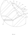
- FIG. 1 is a perspective view of one embodiment of a fluid end attached to one embodiment of a power end.
- FIG. 2 is a cross-sectional view of the fluid end shown in FIG. 1 , taken along line A-A.
- FIG. 3 is the cross-sectional view shown in FIG. 2 , but another embodiment of an intake and a discharge valve are installed therein.
- FIG. 4 is a perspective view of another embodiment of a fluid end attached to another embodiment of a power end.
- FIG. 5 is a cross-sectional view of the fluid end shown in FIG. 4 , taken along line B-B.
- FIG. 6 is a top perspective view of the intake valve and valve seat shown installed within the fluid end in FIG. 2 .
- the valve is shown in a closed position.
- FIG. 7 is a side elevational view of the valve and valve seat shown in FIG. 6 .
- FIG. 8 is the top perspective view of the intake valve and valve seat shown in FIG. 6 , but the valve is shown in an open position.
- FIG. 9 is a side elevational view of the valve and valve seat shown in FIG. 8 .
- FIG. 10 is a cross-sectional view of the valve and valve seat shown in FIG. 7 , taken along line C-C, but the valve is not in a fully closed position.
- FIG. 11 is an enlarged view of area D shown in FIG. 10 , but the valve is shown in a fully closed position.
- FIG. 12 is an enlarged view of area E shown in FIG. 10 .
- FIG. 13 is an enlarged view of area G shown in FIG. 12 .
- FIG. 14 is an enlarged view of area J shown in FIG. 15 .
- FIG. 15 is an enlarged view of area D shown in FIG. 10 .
- FIG. 16 is a top perspective view of the intake valve and valve seat shown installed within the fluid end in FIG. 3 .
- the valve is shown in a closed position.
- FIG. 17 is a side elevational view of the valve and valve seat shown in FIG. 16 .
- FIG. 18 is a cross-sectional view of the valve and valve seat shown in FIG. 17 , taken along line K-K.
- FIG. 19 is the cross-sectional view of the valve and valve seat shown in FIG. 18 , but the valve is shown in an open position.
- FIG. 20 is an enlarged view of area M shown in FIG. 22 .
- FIG. 21 is an enlarged view of area N shown in FIG. 20 .
- FIG. 22 is an enlarged view of area O shown in FIG. 18 .
- FIG. 23 is a top perspective view of another embodiment of a valve and the valve seat. The valve is shown in a closed position.
- FIG. 24 is a side elevational view of the valve and valve seat shown in FIG. 23 .
- FIG. 25 is a cross-sectional view of the valve and valve seat shown in FIG. 24 , taken along line Q-Q.
- FIG. 26 is an enlarged view of area T shown in FIG. 25 .
- FIG. 27 is an enlarged view of area U shown in FIG. 26 .
- FIG. 28 is an enlarged view of area V shown in FIG. 27 .
- FIG. 29 is a cross-sectional view of another embodiment of a valve and the valve seat. The valve is shown in an almost closed position.
- FIG. 30 in an enlarged view of area X shown in FIG. 29 .
- FIG. 31 is a top perspective view of another embodiment of a valve and the valve seat. The valve is shown in a closed position.
- FIG. 32 is a side elevational view of the valve and valve seat shown in FIG. 31 .
- FIG. 33 is a cross-sectional view of the valve and valve seat shown in FIG. 32 , taken along line Y-Y. The valve is shown in an almost closed position.
- FIG. 34 is an exploded view of the valve and valve seat shown in FIG. 31 .
- FIG. 35 is an enlarged view of area Z shown in FIG. 33 .
- FIG. 37 is an enlarged view of area AA shown in FIG. 36 .
- FIG. 38 is a cross-sectional view of another embodiment of a valve and the valve seat. The valve is shown in an almost closed position.
- FIG. 40 is a cross-sectional view of another embodiment of a valve and the valve seat. The valve is shown in an almost closed position.
- FIG. 41 is an enlarged view of area AC shown in FIG. 40 .
- Fluid used in high pressure hydraulic fracturing operations is typically pumped through a fluid end at a minimum of 8,000 psi; however, fluid will normally be pumped through a fluid end at pressures around 10,000-15,000 psi during such operations, with spikes up to 22,500 psi.
- the fluid end 10 comprises a housing 16 having a horizontal bore 18 and a vertical bore 20 extending therethrough.
- the horizontal bore 18 opens on opposed front and rear surfaces 22 and 24 of the housing 16
- the vertical bore 20 opens on opposed upper and lower surfaces 26 and 28 of the housing 16 .
- the bores 18 and 20 intersect to form an internal chamber 30 .
- the plunger 14 is installed within the horizontal bore 18 through the opening on the rear surface 24 . As the plunger 14 reciprocates, it pressurizes fluid contained within the internal chamber 30 .
- a plurality of horizontal and vertical bore pairs 18 and 20 may be formed within a single fluid end housing 16 .
- fluid is routed throughout the housing 16 using an intake valve 34 and a discharge valve 36 .
- the valves 34 and 36 are identical and configured to seal against a valve seat 38 .
- the intake valve 34 and corresponding valve seat 38 are positioned below the internal chamber 30
- the discharge valve 36 and corresponding valve seat 38 are positioned above the internal chamber 30 .
- the valves 34 and 36 move between open and closed positions. In the open position, the valve 34 or 36 is spaced from the valve seat 38 , allowing fluid to flow around the valve 34 or 36 .
- the intake valve 34 is shown in the open position in FIG. 2 . In the closed position, the valve 34 or 36 seals against the valve seat 38 , blocking fluid from passing around the valve 34 or 36 .
- the discharge valve 36 is shown in the closed position in FIG. 2 .
- the valves 34 and 36 are biased in a closed position by a spring 40 and moved to an open position by fluid pressure.
- valves 34 and 36 each comprise a seal 42 .
- the seal 42 is compressed against the valve seat 38 , forming a tight seal.
- Seals used with valves are typically made of urethane and molded to the valve body.
- the high fluid pressure within the fluid end has been known to wear and erode the area of the seal contacting the valve seat. Such erosion will cause the valve to fail to seal properly, allowing fluid to leak around the valve.
- the seal is also known to shear or separate from the valve body, allowing fluid to leak around the valve. This leakage reduces the maximum pressure and flow capabilities of the fluid end. Once the valve fails, it will need to be replaced to ensure proper function of the fluid end. The operation of a fluid end must be stopped in order to replace a valve, costing valuable production time and money.
- valves 34 and 36 shown in FIG. 2 The present disclosure describes a plurality of different embodiments of valves, including the valves 34 and 36 shown in FIG. 2 .
- the various embodiments of valves described herein are each designed to reduce wear and erosion to the valve over time, as well as prevent the seal from shearing or separating from the valve body. Such advantages extend the life of the valves disclosed herein as compared to traditional valves. Extending the life of a valve extends production time between valve replacements, saving valuable time and money.
- the fluid end 50 is shown attached to another embodiment of a power end 52 .
- the fluid end 50 comprises a plurality of fluid end sections 54 positioned in a side-by-side relationship.
- Each fluid end section 54 has a single horizontal bore 56 formed therein, as shown in FIG. 5 .
- Fluid is routed throughout the horizontal bore 56 using a fluid routing plug 58 . Fluid enters the horizontal bore 56 through one or more intake or suction conduits 60 and discharges from the horizontal bore 56 through one or more discharge conduits 62 , as shown in FIG. 5 .
- valve 34 is shown in more detail. Because the valves 34 and 36 are identical, only the valve 34 will be described in detail herein.
- the valve 34 is shown in the closed position, engaging the valve seat 38 in FIGS. 6 and 7 , and is shown in the open position, spaced from the valve seat 38 in FIGS. 8 and 9 .
- the valve 34 comprises a valve body 70 having a tapered sealing surface 72 joined to a side surface 74 by a recessed surface 76 .
- the side surface 74 is further joined to an upper surface 78 of the valve body 70 .
- a nose 80 projects from the upper surface 78 and is configured to engage the spring 40 , as shown in FIG. 2 .
- the tapered sealing surface 72 is further joined to a lower surface 82 of the valve body 70 .
- a plurality of legs 84 extend from the lower surface 82 in a downward direction. The plurality of legs 84 are configured to center the valve 34 within a flow passage 86 formed in the valve seat 38 . The legs 84 ensure the valve 34 is properly aligned with the valve seat 38 during operation.
- the recessed surface 76 forms a recess 88 within the valve body 70 .
- the seal 42 is installed within the recess 88 and engages the recessed surface 76 .
- the seal 42 is made of urethane and molded to the valve body 70 to form the valve 34 .
- the tapered sealing surface 72 and a portion of the seal 42 engage a tapered strike face 90 formed at the top of the valve seat 38 , as shown in FIG. 11 .
- R 4 transitions into the side surface 74 .
- L 1 is positioned intermediate the tapered sealing surface 72 and R 1
- L 2 is positioned intermediate R 1 and R 2
- L 3 is positioned intermediate R 2 and R 3
- L 4 is positioned intermediate R 3 and R 4
- R 4 is positioned intermediate L 4 and the side surface 74 .
- the side surface 74 comprises a straight-line segment, L 5 and a radius segment, R 5 .
- L 5 is generally vertical and is positioned intermediate R 4 and R 5 .
- R 5 transitions into the upper surface 78 .
- L 5 is preferably less than L 3 , but greater than L 1 .
- R 5 is generally equal in size to R 4 .
- the seal 42 is installed within the recess 88 such that the seal 42 engages L 1 , L 2 , L 3 , L 4 , L 5 , R 1 , R 2 , R 3 , R 4 , and R 5 . When installed therein, the seal 42 covers the side surface 74 and an edge 92 of the seal 42 meets the upper surface 78 of the valve body 70 .
- the flange 94 also forces the seal 42 in a specific direction rather than allowing the pressure imposed on the seal 42 by the valve seat 38 to dictate the seal's movement when compressed. Forcing the seal 42 in a specific direction helps prevent the seal 42 from wrapping around an edge 96 of the valve seat 38 during operation. Such action is known to cause damage to traditional seals.
- the seal 42 comprises a strike face 98 joined to an outer face 100 .
- the strike face 98 engages the valve seat 38 in addition to the tapered sealing surface 72 during operation, as shown in FIG. 11 .
- the strike face 98 comprises a first section 102 joined to a second section 104 , as shown in FIG. 14 .
- the first section 102 contacts the tapered sealing surface 72 while the second section 104 transitions into the outer face 100 .
- a profile of the area of contact between the strike face 98 of the seal 42 and the tapered strike face 90 of the valve seat 38 has a length, F.
- F starts at F 1 , which is a point that aligns with the point of contact between the tapered sealing surface 72 and the first section 102 of the strike face 98 .
- F ends at F 2 , which is a point that aligns with the end of the second section 104 of the strike face 98 or the point where the second section 104 transitions into the outer face 100 of the seal 42 .
- Point, P may be positioned anywhere between 60-80% of the total length of F, measured from F 1 .
- point, P is located at 74% of the total length of F.
- F is 0.430 inches
- point, P will be located anywhere between 0.258-0.344 inches or 0.6F-0.8F, along F.
- the distance is 0.218 inches, or 0.74F.
- the inflection point, I may be located anywhere between 30-50% of the total length of F, measured from F 1 .
- F is 0.430 inches
- the inflection point, I is located anywhere between 0.129-0.215 inches or 0.3F-0.5F.
- the strike face 98 and the outer face 100 of the seal 42 are formed as one continuous curve. There are no straight sections. This gradual curve provides a smoother, less turbulent fluid flow around the seal 42 with lower velocities.
- the continuous curve of the outer face 100 also prevents the seal 42 from wrapping around the edge 96 of the valve seat 38 during operation.
- the one continuous curve may be a splined curve. In alternative embodiments, the one continuous curve may be other types of curves known in the art as long as there are no straight sections in the curve. Because the outer face 100 is shaped from one continuous curve, the outer face 100 does not include any bulbous protrusions or channels, like those shown in U.S. Pat. No. 9,631,739, issued to Belshan, and U.S. Pat. No. 10,221,848 and 11,111,915, both issued to Bayyouk.
- the height, H of the seal 42 is measured perpendicular from the strike face 98 to the maximum diametric extension of radius segment, R 5 .
- the width, W of the seal 42 is measured from straight-line segment, L 2 to the same maximum diametric extension of radius segment, R 5 .
- the ratio of the height, H of the seal 42 to the width, W of the seal 42 , H:W may range from 4.5:6 to 5.5:6. Preferably, the ratio is 5:6. Such ratio has been found to optimally reduce stress and strain on the seal 42 during operation.
- the upper surface 120 of the valve 41 comprises an outer rim 117 joined to a base 115 .
- a spring 119 used with the valve 41 engages the valve 41 on the outer rim 117 , as shown in FIG. 3 .
- the spring 119 has a conical shape in order to extend between the outer rim 117 and the valve retainer 128 or discharge plug 129 .
- the stem 124 projects from the base 115 of the upper surface 120 .
- the outer rim 117 and the base 115 are shaped such that an annular void 121 surrounds a portion of the stem 124 .
- the annular void 121 reduces the weight of the valve 41 and helps orient the valve's center of gravity during operation.
- the recessed surface 118 forms a recess 130 within the valve body 112 for receiving a seal 132 .
- the seal 132 comprises a strike face 134 joined to an outer face 136 .
- the strike face 134 and the outer face 136 are identical to the strike face 98 and the outer face 100 of the seal 42 .
- the recessed surface 118 the seal 132 engages is different from the recessed surface 76 formed in the valve body 70 .
- the side surface 116 of the valve body 112 comprises a radius segment, R 3 .
- R 3 transitions into the upper surface 120 of the valve body 112 .
- R 3 is positioned intermediate L 3 and the upper surface 120 .
- the shape of L 3 and R 3 forms a flange 138 at a top end of the valve 41 .
- the flange 138 provides the same advantages as the flange 94 formed on the valve 34 .
- straight-line segment, L 1 extends at a 0-10-degree angle counterclockwise from vertical, preferably 5-degrees, as shown in FIG. 21 .
- Straight-line segment, L 2 may be at a 25-35-degree angle counter-clockwise from vertical, preferably 30-degrees.
- Straight-line segment, L 3 may be at a 10-20-degree angle counterclockwise from horizontal, preferably 15-degrees. While the specific values of L 1 , L 2 , and L 3 may vary depending on the size of the valve 41 , the relationship between the plurality of line segments are preferably: L 3 >L 2 >L 1 .
- FIGS. 23 - 28 another embodiment of a valve 150 is shown.
- the valve 150 may be used as a discharge or an intake valve.
- the valve 150 comprises a valve body 152 having a tapered sealing surface 154 joined to an upper surface 156 by an intermediate surface 158 , as shown in FIGS. 25 and 26 .
- the tapered sealing surface 154 further joins a lower surface 159 .
- a plurality of legs 161 project from the lower surface 159 , making the valve 150 a leg-guided valve.
- a profile of the intermediate surface 158 of the valve body 152 comprises a plurality of straight-line segments: L 1 and L 2 , and a plurality of radius segments: R 1 and R 2 .
- L 1 joins the tapered sealing surface 154 and transitions into R 1 , as shown in FIG. 28 .
- R 1 transitions into L 2
- L 2 transitions into R 2
- R 2 joins the upper surface 156 of the valve body 152 , as shown in FIG. 27 .
- L 1 is positioned intermediate the tapered sealing surface 154 and R 1
- L 2 is positioned intermediate R 1 and R 2
- R 2 is positioned intermediate L 2 and the upper surface 156 .
- the outer face 166 has an even more gradual curve than the outer faces 100 and 136 such that it has a less rounded shape. Instead, an upper portion of the outer face 166 has a more sloped shape, such that the edge 162 of the seal is positioned farther away from an outer edge 96 of the valve seat 38 than the seals 42 and 132 .
- Such construction of the seal 160 helps prevent the seal 160 from wrapping around the edge 96 of the valve seat 38 during operation because no portion of the seal extends past the outermost diameter of the tapered strike face 90 .
- the outer face 166 does not include any bulbous protrusions or channels.
- the shape of the intermediate surface 158 and the shape of the attached seal 160 exposes the entire outer face 166 of the seal 160 to the fluid pressure within the fluid end.
- the pressure applies a force perpendicular to the surface of the outer face 166 of the seal 160 at every point along the outer face 166 .
- the resultant force presses the seal 160 into the valve body 152 , thereby reducing the shearing effect of the fluid flow as it exits the valve 150 .
- valve 150 is shown with another embodiment of a valve spring 168 .
- the spring 168 is identical to the spring 40 , but a bottom end 170 of the spring 168 is squared and ground to provide a more even force application to the upper surface 156 of the valve body 152 , as shown in FIG. 26 .
- a top end 172 of the spring 168 is ground so as to better engage a valve retainer, as shown in FIGS. 23 and 24 .
- Such modifications or like modifications may be made to any of the springs used with the various embodiments of valves disclosed herein so as to provide a more even force application to the corresponding surfaces.
- FIGS. 29 and 30 another embodiment of a valve 180 is shown.
- the valve 180 may be used as a discharge or an intake valve.
- the valve 180 comprises the valve body 152 used with the valve 150 , but the valve 180 uses a different embodiment of a seal 182 .
- the seal 182 comprises a strike face 184 joined to an outer face 186 , as shown in FIG. 30 .
- the strike face 184 is identical to the strike face 164 of the seal 160 , but the seal 182 has another embodiment of an outer face 186 .
- the outer face 186 of the seal 182 is not a splined curve. Instead, the outer face 186 comprises two straight-line segments: L 3 and L 4 , and a radius segment: R 3 .
- L 3 joins a transition section 190 to the outer face 186 .
- the transition section 190 joins the strike face 184 to the outer face 186 .
- L 3 transitions into L 4
- L 4 transitions into R 3 .
- R 3 is joined to the upper surface 156 of the valve body 152 .
- L 3 is positioned intermediate the strike face 184 and L 4 . More specifically, L 3 is positioned intermediate the transition section 190 and L 4 .
- L 4 is positioned intermediate L 3 and R 3
- R 3 is positioned intermediate L 4 and the upper surface 156 .
- L 3 extends perpendicular to the tapered strike face 90 of the valve seat 38 and is parallel to L 2 of the intermediate surface 158 of the valve body 152 .
- L 3 preferably extends at an angle that is 30-degrees counterclockwise from vertical. The angle may have a range of plus or minus 5-degrees, with the intent that L 3 maintains the desired perpendicular and parallel relationships with the valve seat 38 and valve body 152 .
- L 4 extends at angle between L 3 and R 3 . While the angle shown in FIG. 30 is approximately 45-degrees counterclockwise from vertical, it may be any value greater than the angle of L 3 .
- Such construction of the seal 182 provides a tapering of the outer face 186 towards the upper surface 156 of the valve body 152 .
- the flat surface provided by L 4 directs the resultant force applied by fluid pressure directly into the valve body 152 , thereby reducing the tensile force attempting to tear the seal 182 away from the valve body 152 during operation.
- the flat surface of the seal 182 created by L 4 directs the resultant force in two directions.
- the first direction is into the valve body 152
- the second direction is perpendicular to the strike face 184 .
- the direction of such forces counteracts the upward force applied by fluid as it exits the valve 180 and the upward force applied by the closing of the valve 180 , thereby reducing the shear between the seal 182 and the intermediate surface 158 of the valve body 152 .
- the valve 200 may be used as a discharge or an intake valve.
- the valve 200 comprises the valve 180 and a conical sleeve 202 .
- the conical sleeve 202 is shaped to fit over the outer face 186 of the seal 182 and acts as a retaining mechanism for the seal 182 during operation.
- the conical sleeve 202 also protects the outer face 186 of the seal 182 from erosion during operation.
- the use of the conical sleeve 202 also requires the valve 200 to use another embodiment of a spring 204 , which will be described in more detail herein.
- the conical sleeve 202 comprises a body 206 having an inner face 208 and an outer face 210 .
- the body 206 further comprises a lip 212 formed around the outer face 210 and at a bottom end of the body 206 .
- the lip 212 is sized to receive a bottom end 216 of the spring 204 .
- the inner face 208 of the sleeve 202 is congruent to straight-line segment, L 4 of the outer face 186 of the seal 182 , as shown in FIG. 35 .
- the conical sleeve 202 is installed on the valve 180 such that the outer face 186 of the seal 182 engages the inner face 208 of the sleeve 202 .
- the sleeve 202 is held against the seal 182 by tension applied by the spring 204 . Thus, the sleeve 202 is easily separated from the seal 182 , if needed. The sleeve 202 only contacts the seal 182 and the spring 204 . The sleeve 202 does not contact any portion of the valve body 152 , the valve seat 38 , or the fluid end.
- the spring 204 in order to rest within the lip 212 of the sleeve 202 , the spring 204 has a conical shape, similar to the spring 119 shown in FIG. 3 .
- the bottom end 216 of the spring 204 has a greater diameter than the springs 40 and 168 , while a top end 218 of the spring 204 has the same diameter as the springs 40 and 168 .
- the increased diameter at the bottom end 216 of the spring 204 provides stability and leverage to keep the seal 182 contained within the sleeve 202 .
- the actual diameters of the springs 40 , 119 , 168 , and 204 may vary depending upon the size of the valve used.
- the spring 204 may be squared and/or ground at its ends like the spring 168 , if desired.
- the spring 204 and the sleeve 202 may be separate pieces that are held together by compression during operation. Alternatively, the spring 204 may be welded to the sleeve 202 or attached by other methods known in the art.
- valve 250 may be used as a discharge or an intake valve.
- the valve 250 comprises a valve body 252 .
- the valve body 252 is identical to the valve body 152 , but the valve body 252 comprises another embodiment of an intermediate surface 254 .
- the intermediate surface 254 is identical to the intermediate surface 158 but comprises a groove 256 formed within straight-line segment, L 2 .
- a bottom surface 258 of the groove 256 has a negative slope, as viewed from the center of the valve body 252 toward the outer diameter of the valve body 252 .
- the valve 250 further comprises another embodiment of a seal 260 .
- the seal 260 is identical to the seal 182 , but an inner surface 262 of the seal 260 comprises a protrusion 264 sized to correspond with the shape of the groove 256 .
- the protrusion 264 and the groove 256 together act as a locking mechanism 266 between the valve body 252 and the seal 260 , as shown in FIG. 37 .
- the locking mechanism 266 provides more surface area for the seal 260 and the intermediate surface 254 to interface, thereby reducing the force per unit area applied to such interface.
- the locking mechanism 266 also provides varying angles at the interface between the seal 260 and the intermediate surface 254 . The varying angles interrupt the application of the shear force along such interface, thereby increasing the life of the bond between the seal 260 and the valve body 252 .
- valve 250 also used the conical sleeve 202 and spring 204 used with the valve 200 .
- valve 250 may not use the conical sleeve 202 and instead be used with the spring 40 or 168 , shown in FIGS. 2 and 23 .
- FIGS. 38 and 39 another embodiment of a valve 280 is shown.
- the valve 280 is identical to the valve 250 , but the valve 280 comprises another embodiment of a locking mechanism 282 .
- the intermediate surface 284 of the valve 280 comprises a plurality of grooves 286 formed along its length.
- a bottom surface 288 of each groove 286 has a negative slope.
- the valve 280 further uses another embodiment of a seal 290 .
- the seal 290 is identical to the seal 260 but comprises a plurality of protrusions 292 .
- Each protrusion 292 is sized to mate with a corresponding one of the grooves 286 .
- the mating protrusions 292 and grooves 286 together form the locking mechanism 282 .
- the locking mechanism 282 provides even more surface area for the seal 290 to interface with the intermediate surface 284 .
- the locking mechanism 282 also provides more interruption points in case the seal 290 begins to separate from the intermediate surface 284 .
- FIGS. 40 and 41 another embodiment of a valve 300 is shown.
- the valve 300 is identical to the valve 280 , but the valve 300 comprises another embodiment of a locking mechanism 302 .
- the locking mechanism 302 is identical to the locking mechanism 282 , but a bottom surface 304 of each groove 306 has a positive slope instead of a negative slope.
- a seal 308 used with the valve 300 comprises a plurality of protrusions 310 .
- the protrusions 310 are identical to the protrusions 292 , but the protrusions 310 are shaped to mate with the positively sloped bottom surface 304 of the grooves 306 . Forming the grooves 306 with a positively sloped bottom surface 304 provides a more sharply angled bottom surface 304 .
- the corresponding shape of the protrusions 310 is harder to tear during operation.
- the grooves 306 also have a smoother transition between adjacent grooves 306 . The smoother transition creates more surface area for the seal 308 to compress
- the valve 300 also uses the conical sleeve 202 and spring 204 used with the valve 200 .
- the valve 300 may not use the conical sleeve 202 and instead be used with the spring 40 or 168 , shown in FIGS. 2 and 23 .
- kits may be useful with the various embodiments of valves disclosed herein.
- One embodiment of a kit may comprise a valve, a conical sleeve, and/or a spring.
- Another embodiment of a kit may further comprise a valve seat.
Landscapes
- Engineering & Computer Science (AREA)
- General Engineering & Computer Science (AREA)
- Mechanical Engineering (AREA)
- Lift Valve (AREA)
Abstract
Description
Claims (15)
Priority Applications (2)
Application Number | Priority Date | Filing Date | Title |
---|---|---|---|
US17/984,406 US11808364B2 (en) | 2021-11-11 | 2022-11-10 | Valve body |
US18/494,074 US12297915B2 (en) | 2021-11-11 | 2023-10-25 | Valve body |
Applications Claiming Priority (4)
Application Number | Priority Date | Filing Date | Title |
---|---|---|---|
US202163278479P | 2021-11-11 | 2021-11-11 | |
US202163281774P | 2021-11-22 | 2021-11-22 | |
US202163289727P | 2021-12-15 | 2021-12-15 | |
US17/984,406 US11808364B2 (en) | 2021-11-11 | 2022-11-10 | Valve body |
Related Child Applications (1)
Application Number | Title | Priority Date | Filing Date |
---|---|---|---|
US18/494,074 Continuation US12297915B2 (en) | 2021-11-11 | 2023-10-25 | Valve body |
Publications (2)
Publication Number | Publication Date |
---|---|
US20230141854A1 US20230141854A1 (en) | 2023-05-11 |
US11808364B2 true US11808364B2 (en) | 2023-11-07 |
Family
ID=86230304
Family Applications (2)
Application Number | Title | Priority Date | Filing Date |
---|---|---|---|
US17/984,406 Active US11808364B2 (en) | 2021-11-11 | 2022-11-10 | Valve body |
US18/494,074 Active US12297915B2 (en) | 2021-11-11 | 2023-10-25 | Valve body |
Family Applications After (1)
Application Number | Title | Priority Date | Filing Date |
---|---|---|---|
US18/494,074 Active US12297915B2 (en) | 2021-11-11 | 2023-10-25 | Valve body |
Country Status (1)
Country | Link |
---|---|
US (2) | US11808364B2 (en) |
Citations (204)
Publication number | Priority date | Publication date | Assignee | Title |
---|---|---|---|---|
US677137A (en) | 1898-10-19 | 1901-06-25 | Bliss E W Co | Pump. |
US1316539A (en) | 1919-09-16 | Thomas btrrtom | ||
US1662725A (en) | 1927-01-27 | 1928-03-13 | Jr Charles Barfield Toney | Piston |
US1822682A (en) | 1928-06-12 | 1931-09-08 | Mallory & Co Inc P R | Valve seat |
US1836498A (en) | 1928-04-24 | 1931-12-15 | Maschf Augsburg Nuernberg Ag | Multicylinder combustion engine |
US2495880A (en) | 1944-01-22 | 1950-01-31 | Alexander S Volpin | Slush pump valve |
US2713522A (en) | 1951-07-18 | 1955-07-19 | Petch Charles Lorenz | Cartridge type packing gland |
US2756960A (en) | 1953-11-03 | 1956-07-31 | Carroll E Church | Valve |
US2771846A (en) | 1954-05-17 | 1956-11-27 | John Blue Company Inc | Variable-capacity metering pump |
US2783810A (en) | 1955-01-03 | 1957-03-05 | Robert A Wrigley | Nut with wedging lock washer and resilient backing washer assembly |
US2828696A (en) | 1955-10-26 | 1958-04-01 | Worthington Corp | Packing for a reciprocating pump |
US2856857A (en) | 1953-06-05 | 1958-10-21 | Milton Roy Co | Pump |
US2957422A (en) | 1956-01-09 | 1960-10-25 | Dempster Mill Mfg Co | Pumps |
US3005412A (en) | 1960-10-10 | 1961-10-24 | George F Camp | Automatic pressure compensator for reciprocating pumps |
US3053500A (en) | 1957-12-05 | 1962-09-11 | Ute Ind Inc | Valve apparatus |
US3146724A (en) | 1961-11-20 | 1964-09-01 | Armco Steel Corp | Pumps with pulsation damper |
US3152787A (en) | 1963-10-25 | 1964-10-13 | Timmons Albert S Nelson | Floor jack |
US3173648A (en) | 1961-08-14 | 1965-03-16 | Halliburton Co | Flow control devices |
US3179121A (en) | 1961-10-25 | 1965-04-20 | Crane Co | Removable head and seat unit ball valve construction |
US3244424A (en) | 1963-07-19 | 1966-04-05 | Cope Thomas Claude | Stuffing box |
US3257952A (en) | 1964-06-29 | 1966-06-28 | Alan G Mccormick | Bellows pump |
US3301197A (en) | 1964-06-22 | 1967-01-31 | Loughborne Inc | Pump |
US3309013A (en) | 1964-08-03 | 1967-03-14 | Burckhardt Ag Maschf | Arrangements including coaxial suction and delivery valves |
US3373695A (en) | 1966-04-28 | 1968-03-19 | Union Pump Co | Reciprocating piston pump |
US3427988A (en) | 1967-03-21 | 1969-02-18 | United States Steel Corp | Fluid end construction for plunger pumps |
US3463527A (en) | 1968-04-18 | 1969-08-26 | Us Army | Failsafe expandable bolt assembly |
US3474808A (en) | 1967-04-05 | 1969-10-28 | Fwi Inc | High pressure valve for reciprocating pumps |
US3508849A (en) | 1968-01-30 | 1970-04-28 | Du Pont | Compressor valve |
US3589387A (en) | 1969-08-22 | 1971-06-29 | Int Basic Economy Corp | Integrated manifold circuits and method of assembly |
US3679332A (en) | 1970-04-10 | 1972-07-25 | Union Pump Co | Reciprocating piston pump |
US3702624A (en) | 1968-09-17 | 1972-11-14 | Pumpenfabrik Urach | Piston pump |
US3746483A (en) | 1971-04-13 | 1973-07-17 | Pumpenfabrik Urach | Reciprocating piston pump |
US3756229A (en) | 1970-12-14 | 1973-09-04 | Veriflo Corp | Ventilator |
US3887305A (en) | 1972-03-27 | 1975-06-03 | Kazuichi Ito | Reciprocating pump |
US4047850A (en) | 1972-06-02 | 1977-09-13 | Commissariat A L'energie Atomique | Proportioning pump with pneumatic distributor |
US4170214A (en) | 1978-01-23 | 1979-10-09 | Double A Products Company | Hydraulic valve module |
US4174194A (en) | 1976-07-12 | 1979-11-13 | Paul Hammelmann | Reciprocating pump |
US4363463A (en) | 1977-06-08 | 1982-12-14 | Robertshaw Controls Company | Plunger seal assembly and method of making the same |
US4388050A (en) | 1981-03-27 | 1983-06-14 | Geosource, Inc. | Manifold unit and assembly and fluid end assembly |
US4467703A (en) | 1982-08-26 | 1984-08-28 | United States Steel Corporation | Reciprocable pump |
US4470771A (en) | 1982-08-20 | 1984-09-11 | Towler Hydraulics, Inc. | Quadraplex fluid pump |
US4494415A (en) | 1982-03-25 | 1985-01-22 | Hydra-Rig, Incorporated | Liquid nitrogen pump |
US4518329A (en) | 1984-03-30 | 1985-05-21 | Weaver Joe T | Wear resistant pump valve |
US4520837A (en) | 1984-01-31 | 1985-06-04 | Halliburton Company | Cover retainer |
US4616983A (en) | 1984-02-09 | 1986-10-14 | Uraca Pumpenfabrik Gmbh & Co. Kg | Piston or plunger pump |
US4768933A (en) | 1987-10-19 | 1988-09-06 | Stachowiak J Edward | High pressure reciprocating pump and valve assembly therefor |
US4771801A (en) | 1987-02-02 | 1988-09-20 | Halliburton Services | Protective cover assembly with reverse buckling disc |
US4773833A (en) | 1987-04-13 | 1988-09-27 | Apv Gaulin, Inc. | High pressure homogenizer pump |
US4778347A (en) | 1986-09-15 | 1988-10-18 | Mize Robert L | High production pump for viscous materials and method |
US4861241A (en) | 1988-02-08 | 1989-08-29 | Parker Technology, Inc. | Valve guide bracket |
US4878815A (en) | 1988-05-18 | 1989-11-07 | Stachowiak J Edward | High pressure reciprocating pump apparatus |
US4891241A (en) | 1987-04-28 | 1990-01-02 | Dainippon Ink & Chemicals, Inc. | Method of increasing the dynamical strength of glass container |
US4948349A (en) | 1987-09-22 | 1990-08-14 | Yoshinobu Koiwa | Pump and valve apparatus |
US4984970A (en) | 1986-10-22 | 1991-01-15 | Karl Eickmann | Arrangements on coned rings which are applicable in high pressure pumps and related devices |
US5059101A (en) | 1989-01-23 | 1991-10-22 | Valavaara Viljo K | Fluid end |
US5061159A (en) | 1990-08-27 | 1991-10-29 | Pryor Dale H | Fluid end for reciprocating pump |
US5073096A (en) | 1990-10-10 | 1991-12-17 | Halliburton Company | Front-discharge fluid end for reciprocating pump |
US5088521A (en) | 1990-10-29 | 1992-02-18 | Harrisburg, Inc. | Mud pump valve |
US5127807A (en) | 1990-07-26 | 1992-07-07 | Halliburton Company | Ultra high pressure field end for a reciprocating pump |
US5145340A (en) | 1990-06-25 | 1992-09-08 | Dowell Schlumberger Incorporated | Packing for piston and valve machine |
US5207242A (en) | 1992-07-09 | 1993-05-04 | A. Y. Mcdonald Mgf. Co. | Angle dual check valve |
US5226445A (en) | 1992-05-05 | 1993-07-13 | Halliburton Company | Valve having convex sealing surface and concave seating surface |
US5230363A (en) | 1991-04-10 | 1993-07-27 | Dowell Schlumberger Incorporated | Suction valve for high pressure slurry pump |
US5253987A (en) | 1992-04-03 | 1993-10-19 | Harrison Curtis W | Fluid end for high-pressure fluid pumps |
US5299921A (en) | 1992-09-10 | 1994-04-05 | Halliburton Company | Manifold for a front-discharge fluid end reciprocating pump |
US5302087A (en) | 1993-04-29 | 1994-04-12 | Butterworth Jetting Systems, Inc. | High pressure pump with loaded compression rods and method |
US5362215A (en) | 1993-05-10 | 1994-11-08 | Halliburton Company | Modular pump cylinder-head having integral over-pressure protection |
US5370148A (en) | 1994-04-25 | 1994-12-06 | Shafer; Terry C. | Butterfly valve assembly and method of manufacture |
US5507219A (en) | 1994-02-08 | 1996-04-16 | Stogner; Huey | Fail-safe linkage for a reciprocating pump |
US5524902A (en) | 1995-03-14 | 1996-06-11 | Cornette; Kevin R. | Method and cartridge seal for packaging a valve |
US5605449A (en) | 1996-01-25 | 1997-02-25 | Wendy Buskop | Suction and discharge valve arrangement for a high pressure piston pump |
US5636975A (en) | 1994-04-04 | 1997-06-10 | Reynolds Metals Company | Inlet and discharge valve arrangement for a high pressure pump |
USD383053S (en) | 1994-02-09 | 1997-09-02 | Wfi International, Inc. | Tapered socket welded coupling |
US5848880A (en) | 1996-02-06 | 1998-12-15 | Paul Hammelmann Maschinenfabrik Gmbh | Axial valve arrangement for a high pressure plunger pump |
US6164318A (en) | 1999-12-03 | 2000-12-26 | Dixon; Kenneth | Valve locking system |
US6167959B1 (en) | 1998-11-09 | 2001-01-02 | Auto Pax Products, L.L.C. | Adjustable stuffing boxes for pump rods |
US6231323B1 (en) | 1999-01-15 | 2001-05-15 | Jetstream Of Houston, Inc. | High pressure reciprocating pump |
US6257626B1 (en) | 1999-04-27 | 2001-07-10 | Flow-Rite Controls, Ltd. | Connector for fluid handling system |
US6382940B1 (en) | 2000-07-18 | 2002-05-07 | George H. Blume | High pressure plunger pump housing and packing |
US6419459B1 (en) | 2000-10-02 | 2002-07-16 | Gardner Denver, Inc. | Pump fluid cylinder mounting assembly |
US20020166588A1 (en) | 2001-05-10 | 2002-11-14 | Dean Robert H. | Pressure relief valve with field-replaceable high corrosion-resistant components |
US6544012B1 (en) | 2000-07-18 | 2003-04-08 | George H. Blume | High pressure plunger pump housing and packing |
US6641112B2 (en) | 2001-03-23 | 2003-11-04 | Hector Alberto Antoff | Seat support and threaded seat for valve with quadruple seat |
US20040170507A1 (en) | 2002-06-19 | 2004-09-02 | Vicars Berton L. | Fluid end |
US20040234404A1 (en) | 2003-05-20 | 2004-11-25 | Vicars Berton L. | Fluid end assembly |
US6910871B1 (en) | 2002-11-06 | 2005-06-28 | George H. Blume | Valve guide and spring retainer assemblies |
US20060002806A1 (en) | 2004-07-01 | 2006-01-05 | Dixie Iron Works, Ltd. | Fluid end for a plunger pump |
US20060027779A1 (en) | 2004-08-06 | 2006-02-09 | Mcguire Bob | High-pressure plug valve with replaceable inserts and method of refurbishing same |
US7140211B2 (en) | 2003-10-29 | 2006-11-28 | Tremcar Inc. | Tamper detection security for a tank trailer |
US7168440B1 (en) | 2002-06-25 | 2007-01-30 | Blume George H | Valve body and seal assembly |
US7290560B2 (en) | 2004-04-13 | 2007-11-06 | Helmerich & Payne, Inc. | Valve cover locking system |
US7296591B2 (en) | 2002-03-21 | 2007-11-20 | National Oilwell Norway A/S | Valve arrangement for reciprocating machinery such as a pump and an compressor |
US20080006089A1 (en) | 2006-07-07 | 2008-01-10 | Sarmad Adnan | Pump integrity monitoring |
US20080008605A1 (en) | 2006-07-07 | 2008-01-10 | Siemens Automotive Hydraulics Sa | Transfer pump with several pistons |
US20080093361A1 (en) | 2004-05-04 | 2008-04-24 | Spicket Valves And Pumps Limited | Valve Cap |
US20080181798A1 (en) | 2007-01-29 | 2008-07-31 | Victory Rig Equipment Corporation | Fluid pump drive |
US20080279705A1 (en) | 2007-05-11 | 2008-11-13 | Toshimichi Wago | Externally Assisted Valve for a Positive Displacement Pump |
US7506574B2 (en) | 2004-03-11 | 2009-03-24 | Gardner Denver, Inc. | Self-tightening cover for pump |
US7513759B1 (en) | 2003-07-03 | 2009-04-07 | Blume George H | Valve guide and spring retainer assemblies |
US7513483B1 (en) | 2002-06-25 | 2009-04-07 | Blume George H | Valve body and seal assembly |
US20090194717A1 (en) | 2008-02-01 | 2009-08-06 | Hammelmann Maschinenfabrik Gmbh | High-pressure valve assembly |
US7591450B1 (en) | 2001-04-16 | 2009-09-22 | Blume George H | Valve body and seal assembly |
US20100129249A1 (en) | 2007-05-17 | 2010-05-27 | Dresser Italia S.R.L. | Frame for fluid machines |
USD616966S1 (en) | 2009-02-11 | 2010-06-01 | Kmt Waterjet Systems Inc. | Outer follower element for a high pressure seal |
US7789133B2 (en) | 2008-03-20 | 2010-09-07 | Stinger Wellhead Protection, Inc. | Erosion resistant frac head |
US20100243255A1 (en) | 2009-03-31 | 2010-09-30 | Rajesh Luharuka | Apparatus and Method for Oilfield Material Delivery |
US7828053B2 (en) | 2007-04-17 | 2010-11-09 | Stinger Wellhead Protection, Inc. | Multipart frac head with replaceable components |
US7845413B2 (en) | 2006-06-02 | 2010-12-07 | Schlumberger Technology Corporation | Method of pumping an oilfield fluid and split stream oilfield pumping systems |
US7866346B1 (en) | 2008-01-07 | 2011-01-11 | Walters Jimmy A | Mud pump receiving flange and plug retainer |
USD631142S1 (en) | 2009-02-11 | 2011-01-18 | Kmt Waterjet Systems Inc. | Inner packing element for a high pressure seal |
US20110079302A1 (en) | 2009-10-07 | 2011-04-07 | Weir Spm, Inc. | Pump Valve with Full Elastomeric Contact on Seat |
US7963502B2 (en) | 2006-08-25 | 2011-06-21 | Fisher Controls International Llc | Low friction live-loaded packing |
US20110173814A1 (en) | 2009-11-16 | 2011-07-21 | Weir Spm, Inc. | Valve Seat Installation and Retrieval Tool |
US20110189040A1 (en) | 2010-01-29 | 2011-08-04 | Vicars Berton L | Fluid end |
US20110206547A1 (en) | 2010-02-24 | 2011-08-25 | Korea Institute Of Geoscience And Mineral Resources | Sludge suction apparatus for offshore structure |
US20110206546A1 (en) | 2010-02-24 | 2011-08-25 | Vicars Berton L | Fluid end assembly |
US20110236238A1 (en) | 2008-12-08 | 2011-09-29 | Bentec Gmbh Drilling & Oilfield Systems | Clamping device for cylinder sleeves and use thereof, and mud pump having a clamping |
US8083504B2 (en) | 2007-10-05 | 2011-12-27 | Weatherford/Lamb, Inc. | Quintuplex mud pump |
US8100407B2 (en) | 2004-03-11 | 2012-01-24 | Stanton Eddie N | Packing cartridges and pressure-dampening elements for plunger-type pumps |
US20120063936A1 (en) | 2010-09-10 | 2012-03-15 | Phoinix Global LLC | Modular fluid end for a multiplex plunger pump |
US8141849B1 (en) | 2001-04-16 | 2012-03-27 | Blume George H | Valve body and seal assembly |
US20120141308A1 (en) | 2010-12-07 | 2012-06-07 | Saini Rajesh K | Polymeric Pump Parts |
US20120187321A1 (en) | 2011-01-21 | 2012-07-26 | Frac Tech Services, Llc | Easily Replaceable Valve Assembly for a High Pressure Pump |
US20120272764A1 (en) | 2011-04-28 | 2012-11-01 | Gary Pendleton | Modular pump design |
US20130020521A1 (en) | 2011-04-14 | 2013-01-24 | S.P.M. Flow Control, Inc. | Preconfigured seal for valve assemblies |
US8360094B2 (en) | 2003-03-20 | 2013-01-29 | Nord-Lock Switzerland Gmbh | Apparatus to mechanically load a compression member |
US8365754B2 (en) | 2008-08-27 | 2013-02-05 | National Oilwell Varco, L.P. | Valve cover assembly and method of using the same |
US20130045123A1 (en) | 2010-04-30 | 2013-02-21 | Timothy S. Roman | Internal bellows pump fluid path |
US20130105175A1 (en) | 2011-11-01 | 2013-05-02 | Baker Hughes Incorporated | Frangible pressure control plug, actuatable tool including the plug, and method thereof |
US20130112074A1 (en) | 2011-11-03 | 2013-05-09 | FTS International, LLC | Support Mechanism for the Fluid End of a High Pressure Pump |
US20130202458A1 (en) | 2012-02-03 | 2013-08-08 | S.P.M. Flow Control, Inc. | Pump fluid cylinder including load transfer shoulder and valve seat for same |
US8528462B2 (en) | 2009-12-15 | 2013-09-10 | Gardner Denver Water Jetting Systems, Inc. | Coupling arrangement providing an axial space between a plunger and plunger adaptor of a high pressure fluid pump |
US20130319220A1 (en) | 2010-10-19 | 2013-12-05 | Schlumberger Technology Corporation | Fluid End Reinforced With Abrasive Resistant Insert, Coating Or Lining |
US8701546B2 (en) | 2009-12-15 | 2014-04-22 | Gardner Denver Water Jetting Systems, Inc. | Coupling arrangement providing an axial space between a plunger and plunger adaptor of a high pressure fluid pump |
US20140127062A1 (en) | 2012-11-02 | 2014-05-08 | Caterpillar Inc. | Variable capacity plunger pump |
US20140196883A1 (en) | 2013-01-15 | 2014-07-17 | Oil States Energy Services, Llc | Modular ball drop |
US20140196570A1 (en) | 2013-01-14 | 2014-07-17 | Fts International | Lightened Rotating Member and Method of Producing Same |
WO2014144113A2 (en) | 2013-03-15 | 2014-09-18 | Acme Industries, Inc. | Fluid end with protected flow passages and kit for same |
US20140348677A1 (en) | 2011-09-16 | 2014-11-27 | Manuel Moeller | Positive Displacement Pump and Suction Valve Module Therefor |
US20150071803A1 (en) | 2013-09-09 | 2015-03-12 | Federal Signal Corporation | High Power Reciprocating Pump Manifold and Valve Cartridges |
US20150084335A1 (en) | 2013-09-23 | 2015-03-26 | Brian Farrell | Pipe Coupling System and Methods of Use Thereof |
US9010412B2 (en) | 2011-12-20 | 2015-04-21 | Oil States Energy Services, L.L.C. | Ball drop wellhead control apparatus |
US20150132152A1 (en) | 2007-07-30 | 2015-05-14 | Gerard S. Lazzara | Reinforced Smart Mud Pump |
US20150132157A1 (en) | 2013-11-11 | 2015-05-14 | National Oilwell Varco, L.P. | Plunger Pump, Plunger, and Method of Manufacturing Plunger Pump |
US20150147194A1 (en) | 2012-10-17 | 2015-05-28 | Global Energy Services, Inc. | Segmented fluid end |
US20150144826A1 (en) | 2013-11-26 | 2015-05-28 | S.P.M. Flow Control, Inc. | Valve seats for use in fracturing pumps |
WO2015077001A1 (en) | 2013-11-21 | 2015-05-28 | General Electric Company | Valve for hydraulic fracturing pumps with synthetic diamond inserts |
USD731035S1 (en) | 2014-03-07 | 2015-06-02 | Charles Lo Cicero | Delta ring seal for ball valve seat |
US20150159647A1 (en) | 2013-12-10 | 2015-06-11 | S.P.M. Flow Control, Inc. | Stay rod assembly |
US20150211641A1 (en) | 2014-01-24 | 2015-07-30 | Gardner Denver Water Jetting Systems, Inc. | Valve cartridge assembly with a suction valve in line with a discharge valve and a suction valve seat circumscribing an inlet which the suction valve covers |
US20150219096A1 (en) | 2013-07-23 | 2015-08-06 | Halliburton Energy Services, Inc. | Erosion, Corrosion, and Fatigue Prevention for High-Pressure Pumps |
USD737497S1 (en) | 2014-02-24 | 2015-08-25 | Paul Burgess | Quick change lens gasket |
US20150300332A1 (en) | 2014-04-07 | 2015-10-22 | S.P.M. Flow Control, Inc. | Manifold including mounting plate for fluid end block of reciprocating pump assembly |
US9188121B1 (en) | 2014-12-12 | 2015-11-17 | Forum Us, Inc. | Fluid cylinder block having a stress distributing joint |
USD748228S1 (en) | 2013-01-31 | 2016-01-26 | S.P.M. Flow Control, Inc. | Valve seat |
US20160025082A1 (en) | 2014-07-25 | 2016-01-28 | S.P.M. Flow Control, Inc. | System and method for reinforcing reciprocating pump |
US9291274B1 (en) | 2001-04-16 | 2016-03-22 | Novatech Holdings Corp. | Valve body and seal assembly |
US9328745B2 (en) | 2012-11-05 | 2016-05-03 | Magna Steyr Fahrzeugtechnik Ag & Co Kg | Pressure storage system and method to operate pressure storage system |
US20160123313A1 (en) | 2014-11-05 | 2016-05-05 | Simmons Development, Llc | Pneumatically-operated fluid pump with amplified fluid pressure, and related methods |
US20160160848A1 (en) | 2014-12-03 | 2016-06-09 | Trican Well Service Ltd. | Pumps and methods of pumping fluids into a well bore |
US9371919B2 (en) | 2013-10-10 | 2016-06-21 | PSI Pressure Systems Corp. | High pressure fluid system |
US9416887B2 (en) | 2000-07-18 | 2016-08-16 | George H Blume | Low turbulence valve |
US9435454B2 (en) | 2009-02-23 | 2016-09-06 | George H Blume | Fluid end with carbide valve seat and adhesive dampening interface |
US20160281699A1 (en) | 2012-02-22 | 2016-09-29 | King Nutronics Corporation | Multi-fluid precision calibration pressure source |
US9470226B2 (en) | 2013-03-14 | 2016-10-18 | ValveWorks, LLC | Multi-part valve assembly |
US20160369792A1 (en) | 2015-06-18 | 2016-12-22 | S.P.M. Flow Control, Inc. | Connecting rod and crosshead assembly for enhancing the performance of a reciprocating pump |
US9534473B2 (en) | 2014-12-19 | 2017-01-03 | Evolution Well Services, Llc | Mobile electric power generation for hydraulic fracturing of subsurface geological formations |
US20170002947A1 (en) | 2015-07-02 | 2017-01-05 | S.P.M. Flow Control, Inc. | Valve for Reciprocating Pump Assembly |
US20170089473A1 (en) | 2015-09-29 | 2017-03-30 | Kerr Machine Co. | Sealing high pressure flow devices |
US9631739B2 (en) | 2015-01-27 | 2017-04-25 | Black Horse Llc | Valve and seat assembly for a high pressure pump |
EP2494140B1 (en) | 2009-12-02 | 2017-05-03 | Kevin R. Williams | Permanent magnet direct drive mud pump |
WO2017096488A1 (en) | 2015-12-10 | 2017-06-15 | A.H.M.S., Inc. | Fluid end assembly of a reciprocating pump |
US20170204852A1 (en) | 2016-01-15 | 2017-07-20 | W.H. Barnett, JR. | Segmented fluid end |
US20170211565A1 (en) | 2014-07-31 | 2017-07-27 | Fmc Technologies, Inc. | Pump fluid end assembly mounting system |
US20170218951A1 (en) | 2016-02-01 | 2017-08-03 | Caterpillar Inc. | Fluid End Block for Well Stimulation Pump and Method of Remanufacturing the Same |
US9732746B2 (en) | 2012-09-24 | 2017-08-15 | Gardner Denver, Inc. | Fluid end of a high pressure plunger pump |
WO2017139348A1 (en) | 2016-02-11 | 2017-08-17 | S.P.M. Flow Control, Inc. | Transmission for pump such as hydraulic fracturing pump |
USD806241S1 (en) | 2016-07-07 | 2017-12-26 | Becton, Dickinson And Company | Septum seal |
US20180017173A1 (en) | 2015-09-29 | 2018-01-18 | Kerr Machine Co. | Sealing High Pressure Flow Devices |
US20180045187A1 (en) | 2015-02-25 | 2018-02-15 | A.H.M.S., Inc. | Drive mechanism module for a reciprocating pump |
US20180058447A1 (en) | 2016-08-25 | 2018-03-01 | Kerr Machine Co. | Modular Gland Arrangements For A Fluid End Assembly |
CN207974953U (en) | 2018-03-27 | 2018-10-16 | 宁波合力机泵股份有限公司 | A kind of fluid end of letter body, the pump housing, fuselage consecutive formula composite structure |
WO2018197458A1 (en) | 2017-04-27 | 2018-11-01 | Brose Fahrzeugteile GmbH & Co. Kommanditgesellschaft, Würzburg | Compressor |
US20190011051A1 (en) | 2017-07-10 | 2019-01-10 | Bj Services, Llc | Fluid End for Frac Pump |
US20190017503A1 (en) | 2017-07-14 | 2019-01-17 | Kerr Machine Co. | Fluid End Assembly |
US20190032685A1 (en) | 2017-07-26 | 2019-01-31 | Kerr Machine Co. | Bellows System For Fluid End |
US20190049052A1 (en) | 2015-06-22 | 2019-02-14 | S.P.M. Flow Control, Inc. | Fluid liner wear indicator for suction manifold of reciprocating pump assembly |
US20190063427A1 (en) | 2017-08-24 | 2019-02-28 | Kerr Machine Co. | Tapered Valve Seat |
US10221847B2 (en) | 2013-03-21 | 2019-03-05 | Firstex Industries, Inc. | Fluid end assembly with modified suction block |
US10240597B2 (en) | 2012-02-03 | 2019-03-26 | S.P.M. Flow Control, Inc. | Pump assembly including fluid cylinder and tapered valve seats |
US20190120389A1 (en) | 2017-10-24 | 2019-04-25 | Kerr Machine Co. | Fluid End Valve With Dual Inserts |
US20190128104A1 (en) | 2017-11-02 | 2019-05-02 | Caterpillar Inc. | Method of remanufacturing fluid end block |
US20190136842A1 (en) | 2015-09-29 | 2019-05-09 | Kerr Machine Co. | Multi-Piece Fluid End |
US20190145391A1 (en) | 2016-05-26 | 2019-05-16 | Oldenamp B.V. | Double acting positive displacement fluid pump |
US10352321B2 (en) | 2014-12-22 | 2019-07-16 | S.P.M. Flow Control, Inc. | Reciprocating pump with dual circuit power end lubrication system |
US20190368619A1 (en) | 2017-10-24 | 2019-12-05 | Kerr Machine Co. | Valve With Hardened Insert |
US10677380B1 (en) | 2019-07-26 | 2020-06-09 | Halliburton Energy Services, Inc. | Fail safe suction hose for significantly moving suction port |
US20200182240A1 (en) | 2018-12-10 | 2020-06-11 | Kerr Machine Co. | Fluid End |
US10711778B2 (en) | 2017-04-18 | 2020-07-14 | St9 Gas And Oil, Llc | Frac pump valve assembly |
US20200232455A1 (en) | 2017-11-13 | 2020-07-23 | George H. Blume | Pump With Segmented Fluid End Housing and In-Line Suction Valve |
US10767773B2 (en) | 2017-10-20 | 2020-09-08 | Mando Corporation | Check valve |
US10871227B1 (en) | 2020-01-31 | 2020-12-22 | Black Horse, Llc | Power end of a pump |
US11162479B2 (en) | 2019-11-18 | 2021-11-02 | Kerr Machine Co. | Fluid end |
US11261863B2 (en) | 2019-05-14 | 2022-03-01 | Halliburton Energy Services, Inc. | Flexible manifold for reciprocating pump |
Family Cites Families (5)
Publication number | Priority date | Publication date | Assignee | Title |
---|---|---|---|---|
US3062198A (en) | 1961-11-17 | 1962-11-06 | Nickles Machine Corp | Gas engine fuel injection |
US20140367602A1 (en) * | 2013-06-12 | 2014-12-18 | Smith International, Inc. | Valve member with composite seal |
US10670153B2 (en) | 2014-05-19 | 2020-06-02 | Smith International, Inc. | Pressure pumping valves and methods of making such valves |
US9927036B2 (en) * | 2015-04-27 | 2018-03-27 | Forum Us, Inc. | Valve assembly |
US10718441B2 (en) | 2017-08-07 | 2020-07-21 | S.P.M. Flow Control, Inc. | Valve seat with a hardened sleeve interior and a metal exterior |
-
2022
- 2022-11-10 US US17/984,406 patent/US11808364B2/en active Active
-
2023
- 2023-10-25 US US18/494,074 patent/US12297915B2/en active Active
Patent Citations (223)
Publication number | Priority date | Publication date | Assignee | Title |
---|---|---|---|---|
US1316539A (en) | 1919-09-16 | Thomas btrrtom | ||
US677137A (en) | 1898-10-19 | 1901-06-25 | Bliss E W Co | Pump. |
US1662725A (en) | 1927-01-27 | 1928-03-13 | Jr Charles Barfield Toney | Piston |
US1836498A (en) | 1928-04-24 | 1931-12-15 | Maschf Augsburg Nuernberg Ag | Multicylinder combustion engine |
US1822682A (en) | 1928-06-12 | 1931-09-08 | Mallory & Co Inc P R | Valve seat |
US2495880A (en) | 1944-01-22 | 1950-01-31 | Alexander S Volpin | Slush pump valve |
US2713522A (en) | 1951-07-18 | 1955-07-19 | Petch Charles Lorenz | Cartridge type packing gland |
US2856857A (en) | 1953-06-05 | 1958-10-21 | Milton Roy Co | Pump |
US2756960A (en) | 1953-11-03 | 1956-07-31 | Carroll E Church | Valve |
US2771846A (en) | 1954-05-17 | 1956-11-27 | John Blue Company Inc | Variable-capacity metering pump |
US2783810A (en) | 1955-01-03 | 1957-03-05 | Robert A Wrigley | Nut with wedging lock washer and resilient backing washer assembly |
US2828696A (en) | 1955-10-26 | 1958-04-01 | Worthington Corp | Packing for a reciprocating pump |
US2957422A (en) | 1956-01-09 | 1960-10-25 | Dempster Mill Mfg Co | Pumps |
US3053500A (en) | 1957-12-05 | 1962-09-11 | Ute Ind Inc | Valve apparatus |
US3005412A (en) | 1960-10-10 | 1961-10-24 | George F Camp | Automatic pressure compensator for reciprocating pumps |
US3173648A (en) | 1961-08-14 | 1965-03-16 | Halliburton Co | Flow control devices |
US3179121A (en) | 1961-10-25 | 1965-04-20 | Crane Co | Removable head and seat unit ball valve construction |
US3146724A (en) | 1961-11-20 | 1964-09-01 | Armco Steel Corp | Pumps with pulsation damper |
US3244424A (en) | 1963-07-19 | 1966-04-05 | Cope Thomas Claude | Stuffing box |
US3152787A (en) | 1963-10-25 | 1964-10-13 | Timmons Albert S Nelson | Floor jack |
US3301197A (en) | 1964-06-22 | 1967-01-31 | Loughborne Inc | Pump |
US3257952A (en) | 1964-06-29 | 1966-06-28 | Alan G Mccormick | Bellows pump |
US3309013A (en) | 1964-08-03 | 1967-03-14 | Burckhardt Ag Maschf | Arrangements including coaxial suction and delivery valves |
US3373695A (en) | 1966-04-28 | 1968-03-19 | Union Pump Co | Reciprocating piston pump |
US3427988A (en) | 1967-03-21 | 1969-02-18 | United States Steel Corp | Fluid end construction for plunger pumps |
US3474808A (en) | 1967-04-05 | 1969-10-28 | Fwi Inc | High pressure valve for reciprocating pumps |
US3508849A (en) | 1968-01-30 | 1970-04-28 | Du Pont | Compressor valve |
US3463527A (en) | 1968-04-18 | 1969-08-26 | Us Army | Failsafe expandable bolt assembly |
US3702624A (en) | 1968-09-17 | 1972-11-14 | Pumpenfabrik Urach | Piston pump |
US3589387A (en) | 1969-08-22 | 1971-06-29 | Int Basic Economy Corp | Integrated manifold circuits and method of assembly |
US3679332A (en) | 1970-04-10 | 1972-07-25 | Union Pump Co | Reciprocating piston pump |
US3756229A (en) | 1970-12-14 | 1973-09-04 | Veriflo Corp | Ventilator |
US3746483A (en) | 1971-04-13 | 1973-07-17 | Pumpenfabrik Urach | Reciprocating piston pump |
US3887305A (en) | 1972-03-27 | 1975-06-03 | Kazuichi Ito | Reciprocating pump |
US4047850A (en) | 1972-06-02 | 1977-09-13 | Commissariat A L'energie Atomique | Proportioning pump with pneumatic distributor |
US4174194A (en) | 1976-07-12 | 1979-11-13 | Paul Hammelmann | Reciprocating pump |
US4363463A (en) | 1977-06-08 | 1982-12-14 | Robertshaw Controls Company | Plunger seal assembly and method of making the same |
US4170214A (en) | 1978-01-23 | 1979-10-09 | Double A Products Company | Hydraulic valve module |
US4388050A (en) | 1981-03-27 | 1983-06-14 | Geosource, Inc. | Manifold unit and assembly and fluid end assembly |
US4494415A (en) | 1982-03-25 | 1985-01-22 | Hydra-Rig, Incorporated | Liquid nitrogen pump |
US4470771A (en) | 1982-08-20 | 1984-09-11 | Towler Hydraulics, Inc. | Quadraplex fluid pump |
US4467703A (en) | 1982-08-26 | 1984-08-28 | United States Steel Corporation | Reciprocable pump |
US4520837A (en) | 1984-01-31 | 1985-06-04 | Halliburton Company | Cover retainer |
US4616983A (en) | 1984-02-09 | 1986-10-14 | Uraca Pumpenfabrik Gmbh & Co. Kg | Piston or plunger pump |
US4518329A (en) | 1984-03-30 | 1985-05-21 | Weaver Joe T | Wear resistant pump valve |
US4778347A (en) | 1986-09-15 | 1988-10-18 | Mize Robert L | High production pump for viscous materials and method |
US4984970A (en) | 1986-10-22 | 1991-01-15 | Karl Eickmann | Arrangements on coned rings which are applicable in high pressure pumps and related devices |
US4771801A (en) | 1987-02-02 | 1988-09-20 | Halliburton Services | Protective cover assembly with reverse buckling disc |
US4773833A (en) | 1987-04-13 | 1988-09-27 | Apv Gaulin, Inc. | High pressure homogenizer pump |
US4891241A (en) | 1987-04-28 | 1990-01-02 | Dainippon Ink & Chemicals, Inc. | Method of increasing the dynamical strength of glass container |
US4948349A (en) | 1987-09-22 | 1990-08-14 | Yoshinobu Koiwa | Pump and valve apparatus |
US4768933A (en) | 1987-10-19 | 1988-09-06 | Stachowiak J Edward | High pressure reciprocating pump and valve assembly therefor |
US4861241A (en) | 1988-02-08 | 1989-08-29 | Parker Technology, Inc. | Valve guide bracket |
US4878815A (en) | 1988-05-18 | 1989-11-07 | Stachowiak J Edward | High pressure reciprocating pump apparatus |
US5059101A (en) | 1989-01-23 | 1991-10-22 | Valavaara Viljo K | Fluid end |
US5145340A (en) | 1990-06-25 | 1992-09-08 | Dowell Schlumberger Incorporated | Packing for piston and valve machine |
US5127807A (en) | 1990-07-26 | 1992-07-07 | Halliburton Company | Ultra high pressure field end for a reciprocating pump |
US5061159A (en) | 1990-08-27 | 1991-10-29 | Pryor Dale H | Fluid end for reciprocating pump |
US5073096A (en) | 1990-10-10 | 1991-12-17 | Halliburton Company | Front-discharge fluid end for reciprocating pump |
US5088521A (en) | 1990-10-29 | 1992-02-18 | Harrisburg, Inc. | Mud pump valve |
US5230363A (en) | 1991-04-10 | 1993-07-27 | Dowell Schlumberger Incorporated | Suction valve for high pressure slurry pump |
US5253987A (en) | 1992-04-03 | 1993-10-19 | Harrison Curtis W | Fluid end for high-pressure fluid pumps |
US5226445A (en) | 1992-05-05 | 1993-07-13 | Halliburton Company | Valve having convex sealing surface and concave seating surface |
US5207242A (en) | 1992-07-09 | 1993-05-04 | A. Y. Mcdonald Mgf. Co. | Angle dual check valve |
US5299921A (en) | 1992-09-10 | 1994-04-05 | Halliburton Company | Manifold for a front-discharge fluid end reciprocating pump |
US5302087A (en) | 1993-04-29 | 1994-04-12 | Butterworth Jetting Systems, Inc. | High pressure pump with loaded compression rods and method |
US5362215A (en) | 1993-05-10 | 1994-11-08 | Halliburton Company | Modular pump cylinder-head having integral over-pressure protection |
US5507219A (en) | 1994-02-08 | 1996-04-16 | Stogner; Huey | Fail-safe linkage for a reciprocating pump |
USD383053S (en) | 1994-02-09 | 1997-09-02 | Wfi International, Inc. | Tapered socket welded coupling |
US5636975A (en) | 1994-04-04 | 1997-06-10 | Reynolds Metals Company | Inlet and discharge valve arrangement for a high pressure pump |
US5370148A (en) | 1994-04-25 | 1994-12-06 | Shafer; Terry C. | Butterfly valve assembly and method of manufacture |
US5524902A (en) | 1995-03-14 | 1996-06-11 | Cornette; Kevin R. | Method and cartridge seal for packaging a valve |
US5605449A (en) | 1996-01-25 | 1997-02-25 | Wendy Buskop | Suction and discharge valve arrangement for a high pressure piston pump |
US5848880A (en) | 1996-02-06 | 1998-12-15 | Paul Hammelmann Maschinenfabrik Gmbh | Axial valve arrangement for a high pressure plunger pump |
US6167959B1 (en) | 1998-11-09 | 2001-01-02 | Auto Pax Products, L.L.C. | Adjustable stuffing boxes for pump rods |
US6231323B1 (en) | 1999-01-15 | 2001-05-15 | Jetstream Of Houston, Inc. | High pressure reciprocating pump |
US6257626B1 (en) | 1999-04-27 | 2001-07-10 | Flow-Rite Controls, Ltd. | Connector for fluid handling system |
US6164318A (en) | 1999-12-03 | 2000-12-26 | Dixon; Kenneth | Valve locking system |
US6382940B1 (en) | 2000-07-18 | 2002-05-07 | George H. Blume | High pressure plunger pump housing and packing |
US9416887B2 (en) | 2000-07-18 | 2016-08-16 | George H Blume | Low turbulence valve |
US6544012B1 (en) | 2000-07-18 | 2003-04-08 | George H. Blume | High pressure plunger pump housing and packing |
US6419459B1 (en) | 2000-10-02 | 2002-07-16 | Gardner Denver, Inc. | Pump fluid cylinder mounting assembly |
US6641112B2 (en) | 2001-03-23 | 2003-11-04 | Hector Alberto Antoff | Seat support and threaded seat for valve with quadruple seat |
US8141849B1 (en) | 2001-04-16 | 2012-03-27 | Blume George H | Valve body and seal assembly |
US7591450B1 (en) | 2001-04-16 | 2009-09-22 | Blume George H | Valve body and seal assembly |
US9291274B1 (en) | 2001-04-16 | 2016-03-22 | Novatech Holdings Corp. | Valve body and seal assembly |
US20020166588A1 (en) | 2001-05-10 | 2002-11-14 | Dean Robert H. | Pressure relief valve with field-replaceable high corrosion-resistant components |
US7296591B2 (en) | 2002-03-21 | 2007-11-20 | National Oilwell Norway A/S | Valve arrangement for reciprocating machinery such as a pump and an compressor |
US7335002B2 (en) | 2002-06-19 | 2008-02-26 | Gardner Denver, Inc. | Fluid end |
US20040170507A1 (en) | 2002-06-19 | 2004-09-02 | Vicars Berton L. | Fluid end |
US7168440B1 (en) | 2002-06-25 | 2007-01-30 | Blume George H | Valve body and seal assembly |
US7513483B1 (en) | 2002-06-25 | 2009-04-07 | Blume George H | Valve body and seal assembly |
US7186097B1 (en) | 2002-11-06 | 2007-03-06 | Blume George H | Plunger pump housing and access bore plug |
US6910871B1 (en) | 2002-11-06 | 2005-06-28 | George H. Blume | Valve guide and spring retainer assemblies |
US8360094B2 (en) | 2003-03-20 | 2013-01-29 | Nord-Lock Switzerland Gmbh | Apparatus to mechanically load a compression member |
US20040234404A1 (en) | 2003-05-20 | 2004-11-25 | Vicars Berton L. | Fluid end assembly |
US7513759B1 (en) | 2003-07-03 | 2009-04-07 | Blume George H | Valve guide and spring retainer assemblies |
US7140211B2 (en) | 2003-10-29 | 2006-11-28 | Tremcar Inc. | Tamper detection security for a tank trailer |
US7506574B2 (en) | 2004-03-11 | 2009-03-24 | Gardner Denver, Inc. | Self-tightening cover for pump |
US8100407B2 (en) | 2004-03-11 | 2012-01-24 | Stanton Eddie N | Packing cartridges and pressure-dampening elements for plunger-type pumps |
US7290560B2 (en) | 2004-04-13 | 2007-11-06 | Helmerich & Payne, Inc. | Valve cover locking system |
US20080093361A1 (en) | 2004-05-04 | 2008-04-24 | Spicket Valves And Pumps Limited | Valve Cap |
US20060002806A1 (en) | 2004-07-01 | 2006-01-05 | Dixie Iron Works, Ltd. | Fluid end for a plunger pump |
US20060027779A1 (en) | 2004-08-06 | 2006-02-09 | Mcguire Bob | High-pressure plug valve with replaceable inserts and method of refurbishing same |
US7845413B2 (en) | 2006-06-02 | 2010-12-07 | Schlumberger Technology Corporation | Method of pumping an oilfield fluid and split stream oilfield pumping systems |
US20080008605A1 (en) | 2006-07-07 | 2008-01-10 | Siemens Automotive Hydraulics Sa | Transfer pump with several pistons |
US20080006089A1 (en) | 2006-07-07 | 2008-01-10 | Sarmad Adnan | Pump integrity monitoring |
US7963502B2 (en) | 2006-08-25 | 2011-06-21 | Fisher Controls International Llc | Low friction live-loaded packing |
US20080181798A1 (en) | 2007-01-29 | 2008-07-31 | Victory Rig Equipment Corporation | Fluid pump drive |
US7828053B2 (en) | 2007-04-17 | 2010-11-09 | Stinger Wellhead Protection, Inc. | Multipart frac head with replaceable components |
US8317498B2 (en) | 2007-05-11 | 2012-11-27 | Schlumberger Technology Corporation | Valve-seat interface architecture |
US20080279706A1 (en) | 2007-05-11 | 2008-11-13 | Philippe Gambier | Valve-Seat Interface Architecture |
US20080279705A1 (en) | 2007-05-11 | 2008-11-13 | Toshimichi Wago | Externally Assisted Valve for a Positive Displacement Pump |
US20100129249A1 (en) | 2007-05-17 | 2010-05-27 | Dresser Italia S.R.L. | Frame for fluid machines |
US20150132152A1 (en) | 2007-07-30 | 2015-05-14 | Gerard S. Lazzara | Reinforced Smart Mud Pump |
US8083504B2 (en) | 2007-10-05 | 2011-12-27 | Weatherford/Lamb, Inc. | Quintuplex mud pump |
US7866346B1 (en) | 2008-01-07 | 2011-01-11 | Walters Jimmy A | Mud pump receiving flange and plug retainer |
US20090194717A1 (en) | 2008-02-01 | 2009-08-06 | Hammelmann Maschinenfabrik Gmbh | High-pressure valve assembly |
US8240634B2 (en) | 2008-02-01 | 2012-08-14 | Hammelmann Maschinenfabrik Gmbh | High-pressure valve assembly |
US7789133B2 (en) | 2008-03-20 | 2010-09-07 | Stinger Wellhead Protection, Inc. | Erosion resistant frac head |
US8365754B2 (en) | 2008-08-27 | 2013-02-05 | National Oilwell Varco, L.P. | Valve cover assembly and method of using the same |
US20110236238A1 (en) | 2008-12-08 | 2011-09-29 | Bentec Gmbh Drilling & Oilfield Systems | Clamping device for cylinder sleeves and use thereof, and mud pump having a clamping |
USD616966S1 (en) | 2009-02-11 | 2010-06-01 | Kmt Waterjet Systems Inc. | Outer follower element for a high pressure seal |
USD631142S1 (en) | 2009-02-11 | 2011-01-18 | Kmt Waterjet Systems Inc. | Inner packing element for a high pressure seal |
US9435454B2 (en) | 2009-02-23 | 2016-09-06 | George H Blume | Fluid end with carbide valve seat and adhesive dampening interface |
US20100243255A1 (en) | 2009-03-31 | 2010-09-30 | Rajesh Luharuka | Apparatus and Method for Oilfield Material Delivery |
US20110079302A1 (en) | 2009-10-07 | 2011-04-07 | Weir Spm, Inc. | Pump Valve with Full Elastomeric Contact on Seat |
US20110173814A1 (en) | 2009-11-16 | 2011-07-21 | Weir Spm, Inc. | Valve Seat Installation and Retrieval Tool |
EP2494140B1 (en) | 2009-12-02 | 2017-05-03 | Kevin R. Williams | Permanent magnet direct drive mud pump |
US8701546B2 (en) | 2009-12-15 | 2014-04-22 | Gardner Denver Water Jetting Systems, Inc. | Coupling arrangement providing an axial space between a plunger and plunger adaptor of a high pressure fluid pump |
US8528462B2 (en) | 2009-12-15 | 2013-09-10 | Gardner Denver Water Jetting Systems, Inc. | Coupling arrangement providing an axial space between a plunger and plunger adaptor of a high pressure fluid pump |
US20110189040A1 (en) | 2010-01-29 | 2011-08-04 | Vicars Berton L | Fluid end |
US20110206546A1 (en) | 2010-02-24 | 2011-08-25 | Vicars Berton L | Fluid end assembly |
US20110206547A1 (en) | 2010-02-24 | 2011-08-25 | Korea Institute Of Geoscience And Mineral Resources | Sludge suction apparatus for offshore structure |
US20130045123A1 (en) | 2010-04-30 | 2013-02-21 | Timothy S. Roman | Internal bellows pump fluid path |
US9791082B2 (en) | 2010-09-10 | 2017-10-17 | Forum Us, Inc. | Modular fluid end for a multiplex plunger pump |
US20130263932A1 (en) | 2010-09-10 | 2013-10-10 | Forum Us, Inc. | Modular fluid end for a multiplex plunger pump |
US20120063936A1 (en) | 2010-09-10 | 2012-03-15 | Phoinix Global LLC | Modular fluid end for a multiplex plunger pump |
US20130319220A1 (en) | 2010-10-19 | 2013-12-05 | Schlumberger Technology Corporation | Fluid End Reinforced With Abrasive Resistant Insert, Coating Or Lining |
US20120141308A1 (en) | 2010-12-07 | 2012-06-07 | Saini Rajesh K | Polymeric Pump Parts |
US20120187321A1 (en) | 2011-01-21 | 2012-07-26 | Frac Tech Services, Llc | Easily Replaceable Valve Assembly for a High Pressure Pump |
US20130020521A1 (en) | 2011-04-14 | 2013-01-24 | S.P.M. Flow Control, Inc. | Preconfigured seal for valve assemblies |
US20120272764A1 (en) | 2011-04-28 | 2012-11-01 | Gary Pendleton | Modular pump design |
US20140348677A1 (en) | 2011-09-16 | 2014-11-27 | Manuel Moeller | Positive Displacement Pump and Suction Valve Module Therefor |
US20130105175A1 (en) | 2011-11-01 | 2013-05-02 | Baker Hughes Incorporated | Frangible pressure control plug, actuatable tool including the plug, and method thereof |
US20130112074A1 (en) | 2011-11-03 | 2013-05-09 | FTS International, LLC | Support Mechanism for the Fluid End of a High Pressure Pump |
US9010412B2 (en) | 2011-12-20 | 2015-04-21 | Oil States Energy Services, L.L.C. | Ball drop wellhead control apparatus |
US10240597B2 (en) | 2012-02-03 | 2019-03-26 | S.P.M. Flow Control, Inc. | Pump assembly including fluid cylinder and tapered valve seats |
US20130202458A1 (en) | 2012-02-03 | 2013-08-08 | S.P.M. Flow Control, Inc. | Pump fluid cylinder including load transfer shoulder and valve seat for same |
US20160281699A1 (en) | 2012-02-22 | 2016-09-29 | King Nutronics Corporation | Multi-fluid precision calibration pressure source |
US9732746B2 (en) | 2012-09-24 | 2017-08-15 | Gardner Denver, Inc. | Fluid end of a high pressure plunger pump |
US20150147194A1 (en) | 2012-10-17 | 2015-05-28 | Global Energy Services, Inc. | Segmented fluid end |
US20140127062A1 (en) | 2012-11-02 | 2014-05-08 | Caterpillar Inc. | Variable capacity plunger pump |
US9328745B2 (en) | 2012-11-05 | 2016-05-03 | Magna Steyr Fahrzeugtechnik Ag & Co Kg | Pressure storage system and method to operate pressure storage system |
US20140196570A1 (en) | 2013-01-14 | 2014-07-17 | Fts International | Lightened Rotating Member and Method of Producing Same |
US9260933B2 (en) | 2013-01-15 | 2016-02-16 | Oil States Energy Services, L.L.C. | Modular ball drop |
US20140196883A1 (en) | 2013-01-15 | 2014-07-17 | Oil States Energy Services, Llc | Modular ball drop |
USD748228S1 (en) | 2013-01-31 | 2016-01-26 | S.P.M. Flow Control, Inc. | Valve seat |
USD787029S1 (en) | 2013-01-31 | 2017-05-16 | S.P.M. Flow Control, Inc. | Valve seat |
US9470226B2 (en) | 2013-03-14 | 2016-10-18 | ValveWorks, LLC | Multi-part valve assembly |
WO2014144113A2 (en) | 2013-03-15 | 2014-09-18 | Acme Industries, Inc. | Fluid end with protected flow passages and kit for same |
US10221847B2 (en) | 2013-03-21 | 2019-03-05 | Firstex Industries, Inc. | Fluid end assembly with modified suction block |
US20150219096A1 (en) | 2013-07-23 | 2015-08-06 | Halliburton Energy Services, Inc. | Erosion, Corrosion, and Fatigue Prevention for High-Pressure Pumps |
US20150071803A1 (en) | 2013-09-09 | 2015-03-12 | Federal Signal Corporation | High Power Reciprocating Pump Manifold and Valve Cartridges |
US20150084335A1 (en) | 2013-09-23 | 2015-03-26 | Brian Farrell | Pipe Coupling System and Methods of Use Thereof |
US9371919B2 (en) | 2013-10-10 | 2016-06-21 | PSI Pressure Systems Corp. | High pressure fluid system |
US20150132157A1 (en) | 2013-11-11 | 2015-05-14 | National Oilwell Varco, L.P. | Plunger Pump, Plunger, and Method of Manufacturing Plunger Pump |
WO2015077001A1 (en) | 2013-11-21 | 2015-05-28 | General Electric Company | Valve for hydraulic fracturing pumps with synthetic diamond inserts |
US20150144826A1 (en) | 2013-11-26 | 2015-05-28 | S.P.M. Flow Control, Inc. | Valve seats for use in fracturing pumps |
US20180313456A1 (en) | 2013-11-26 | 2018-11-01 | S.P.M. Flow Control, Inc. | Valve seats for use in fracturing pumps |
US9822894B2 (en) | 2013-11-26 | 2017-11-21 | S.P.M. Flow Control, Inc. | Valve seats for use in fracturing pumps |
US20150159647A1 (en) | 2013-12-10 | 2015-06-11 | S.P.M. Flow Control, Inc. | Stay rod assembly |
US20150211641A1 (en) | 2014-01-24 | 2015-07-30 | Gardner Denver Water Jetting Systems, Inc. | Valve cartridge assembly with a suction valve in line with a discharge valve and a suction valve seat circumscribing an inlet which the suction valve covers |
US9670922B2 (en) | 2014-01-24 | 2017-06-06 | Gardner Denver Water Jetting Systems, Inc. | Pump system including valve cartridge assembly with a suction valve in line with a discharge valve |
USD737497S1 (en) | 2014-02-24 | 2015-08-25 | Paul Burgess | Quick change lens gasket |
USD731035S1 (en) | 2014-03-07 | 2015-06-02 | Charles Lo Cicero | Delta ring seal for ball valve seat |
US20150300332A1 (en) | 2014-04-07 | 2015-10-22 | S.P.M. Flow Control, Inc. | Manifold including mounting plate for fluid end block of reciprocating pump assembly |
US20160025082A1 (en) | 2014-07-25 | 2016-01-28 | S.P.M. Flow Control, Inc. | System and method for reinforcing reciprocating pump |
US20190277341A1 (en) | 2014-07-25 | 2019-09-12 | S.P.M. Flow Control, Inc. | Power end frame assembly for reciprocating pump |
US20170211565A1 (en) | 2014-07-31 | 2017-07-27 | Fmc Technologies, Inc. | Pump fluid end assembly mounting system |
US20160123313A1 (en) | 2014-11-05 | 2016-05-05 | Simmons Development, Llc | Pneumatically-operated fluid pump with amplified fluid pressure, and related methods |
US20160160848A1 (en) | 2014-12-03 | 2016-06-09 | Trican Well Service Ltd. | Pumps and methods of pumping fluids into a well bore |
US9188121B1 (en) | 2014-12-12 | 2015-11-17 | Forum Us, Inc. | Fluid cylinder block having a stress distributing joint |
US9534473B2 (en) | 2014-12-19 | 2017-01-03 | Evolution Well Services, Llc | Mobile electric power generation for hydraulic fracturing of subsurface geological formations |
US10352321B2 (en) | 2014-12-22 | 2019-07-16 | S.P.M. Flow Control, Inc. | Reciprocating pump with dual circuit power end lubrication system |
US20190277279A1 (en) | 2014-12-22 | 2019-09-12 | S.P.M. Flow Control, Inc. | Reciprocating pump with dual circuit power end lubrication system |
US9631739B2 (en) | 2015-01-27 | 2017-04-25 | Black Horse Llc | Valve and seat assembly for a high pressure pump |
US20180045187A1 (en) | 2015-02-25 | 2018-02-15 | A.H.M.S., Inc. | Drive mechanism module for a reciprocating pump |
US20160369792A1 (en) | 2015-06-18 | 2016-12-22 | S.P.M. Flow Control, Inc. | Connecting rod and crosshead assembly for enhancing the performance of a reciprocating pump |
US10393113B2 (en) | 2015-06-18 | 2019-08-27 | S.P.M. Flow Control, Inc. | Connecting rod and crosshead assembly for enhancing the performance of a reciprocating pump |
US20190049052A1 (en) | 2015-06-22 | 2019-02-14 | S.P.M. Flow Control, Inc. | Fluid liner wear indicator for suction manifold of reciprocating pump assembly |
US20170002947A1 (en) | 2015-07-02 | 2017-01-05 | S.P.M. Flow Control, Inc. | Valve for Reciprocating Pump Assembly |
US11111915B2 (en) | 2015-07-02 | 2021-09-07 | SPM Oil & Gas PC LLC | Valve for reciprocating pump assembly |
US20170089473A1 (en) | 2015-09-29 | 2017-03-30 | Kerr Machine Co. | Sealing high pressure flow devices |
US20180017173A1 (en) | 2015-09-29 | 2018-01-18 | Kerr Machine Co. | Sealing High Pressure Flow Devices |
US20190136842A1 (en) | 2015-09-29 | 2019-05-09 | Kerr Machine Co. | Multi-Piece Fluid End |
US10760567B2 (en) | 2015-12-10 | 2020-09-01 | A.H.M.S., Inc. | Fluid end assembly of a reciprocating pump |
WO2017096488A1 (en) | 2015-12-10 | 2017-06-15 | A.H.M.S., Inc. | Fluid end assembly of a reciprocating pump |
US20170204852A1 (en) | 2016-01-15 | 2017-07-20 | W.H. Barnett, JR. | Segmented fluid end |
US10184470B2 (en) | 2016-01-15 | 2019-01-22 | W. H. Barnett, JR. | Segmented fluid end |
US20170218951A1 (en) | 2016-02-01 | 2017-08-03 | Caterpillar Inc. | Fluid End Block for Well Stimulation Pump and Method of Remanufacturing the Same |
WO2017139348A1 (en) | 2016-02-11 | 2017-08-17 | S.P.M. Flow Control, Inc. | Transmission for pump such as hydraulic fracturing pump |
US20190145391A1 (en) | 2016-05-26 | 2019-05-16 | Oldenamp B.V. | Double acting positive displacement fluid pump |
USD806241S1 (en) | 2016-07-07 | 2017-12-26 | Becton, Dickinson And Company | Septum seal |
US20180058447A1 (en) | 2016-08-25 | 2018-03-01 | Kerr Machine Co. | Modular Gland Arrangements For A Fluid End Assembly |
US10711778B2 (en) | 2017-04-18 | 2020-07-14 | St9 Gas And Oil, Llc | Frac pump valve assembly |
WO2018197458A1 (en) | 2017-04-27 | 2018-11-01 | Brose Fahrzeugteile GmbH & Co. Kommanditgesellschaft, Würzburg | Compressor |
US20200191146A1 (en) | 2017-04-27 | 2020-06-18 | Brose Fahrzeugteile GmbH & Co. Kommanditgesellschaft, Würzburg | Compressor |
US20190011051A1 (en) | 2017-07-10 | 2019-01-10 | Bj Services, Llc | Fluid End for Frac Pump |
US20190017503A1 (en) | 2017-07-14 | 2019-01-17 | Kerr Machine Co. | Fluid End Assembly |
US20190032685A1 (en) | 2017-07-26 | 2019-01-31 | Kerr Machine Co. | Bellows System For Fluid End |
US20190063427A1 (en) | 2017-08-24 | 2019-02-28 | Kerr Machine Co. | Tapered Valve Seat |
US10767773B2 (en) | 2017-10-20 | 2020-09-08 | Mando Corporation | Check valve |
US20190368619A1 (en) | 2017-10-24 | 2019-12-05 | Kerr Machine Co. | Valve With Hardened Insert |
US20190120389A1 (en) | 2017-10-24 | 2019-04-25 | Kerr Machine Co. | Fluid End Valve With Dual Inserts |
US20190128104A1 (en) | 2017-11-02 | 2019-05-02 | Caterpillar Inc. | Method of remanufacturing fluid end block |
US20200232455A1 (en) | 2017-11-13 | 2020-07-23 | George H. Blume | Pump With Segmented Fluid End Housing and In-Line Suction Valve |
CN207974953U (en) | 2018-03-27 | 2018-10-16 | 宁波合力机泵股份有限公司 | A kind of fluid end of letter body, the pump housing, fuselage consecutive formula composite structure |
US20200182240A1 (en) | 2018-12-10 | 2020-06-11 | Kerr Machine Co. | Fluid End |
US11261863B2 (en) | 2019-05-14 | 2022-03-01 | Halliburton Energy Services, Inc. | Flexible manifold for reciprocating pump |
US10677380B1 (en) | 2019-07-26 | 2020-06-09 | Halliburton Energy Services, Inc. | Fail safe suction hose for significantly moving suction port |
US11162479B2 (en) | 2019-11-18 | 2021-11-02 | Kerr Machine Co. | Fluid end |
US10871227B1 (en) | 2020-01-31 | 2020-12-22 | Black Horse, Llc | Power end of a pump |
Also Published As
Publication number | Publication date |
---|---|
US12297915B2 (en) | 2025-05-13 |
US20230141854A1 (en) | 2023-05-11 |
US20240068575A1 (en) | 2024-02-29 |
Similar Documents
Publication | Publication Date | Title |
---|---|---|
US11078903B2 (en) | Tapered valve seat | |
US20190120389A1 (en) | Fluid End Valve With Dual Inserts | |
US20190368619A1 (en) | Valve With Hardened Insert | |
US20190072089A1 (en) | Fluid end with curved internal cavity profile | |
CA2922682C (en) | A valve assembly | |
US9562418B2 (en) | Valve with shuttle | |
CN108350874B (en) | Ball cage with directional flow path for ball pump | |
US4796858A (en) | Dual seal valve | |
US20210341079A1 (en) | Fluid End Valve Having Dual Inserts | |
US4531710A (en) | Expanding gate valve | |
US5127661A (en) | Fluid seal | |
CN103370543A (en) | Plunger packing with wedge seal having extrusion recess | |
US11946465B2 (en) | Packing seal assembly | |
KR102718914B1 (en) | Pinch valve | |
US20240288076A1 (en) | Wear-resistant hydraulic fracturing pump valves | |
US11384856B2 (en) | Spherical pump valve | |
US11808364B2 (en) | Valve body | |
CN108240195A (en) | Polished rod sealer | |
US2085360A (en) | Pump valve construction | |
TW202045842A (en) | Spool type switching valve | |
CN115076092B (en) | Plunger and fracturing pump | |
US20230313890A1 (en) | Fluid end valve | |
CN120332499A (en) | Valve core assembly and gate valve | |
GB2488588A (en) | A sealing arrangement for forming a seal between two surfaces in a hydraulic system | |
US20020130289A1 (en) | Low discharge slurry valve seal |
Legal Events
Date | Code | Title | Description |
---|---|---|---|
FEPP | Fee payment procedure |
Free format text: ENTITY STATUS SET TO UNDISCOUNTED (ORIGINAL EVENT CODE: BIG.); ENTITY STATUS OF PATENT OWNER: SMALL ENTITY |
|
AS | Assignment |
Owner name: KERR MACHINE CO., OKLAHOMA Free format text: ASSIGNMENT OF ASSIGNORS INTEREST;ASSIGNORS:THOMAS, MICHEAL COLE;BARNETT, CHRISTOPHER TODD;SON, NICHOLAS;AND OTHERS;REEL/FRAME:061934/0330 Effective date: 20221114 |
|
FEPP | Fee payment procedure |
Free format text: ENTITY STATUS SET TO SMALL (ORIGINAL EVENT CODE: SMAL); ENTITY STATUS OF PATENT OWNER: SMALL ENTITY |
|
STPP | Information on status: patent application and granting procedure in general |
Free format text: RESPONSE TO NON-FINAL OFFICE ACTION ENTERED AND FORWARDED TO EXAMINER |
|
STPP | Information on status: patent application and granting procedure in general |
Free format text: NOTICE OF ALLOWANCE MAILED -- APPLICATION RECEIVED IN OFFICE OF PUBLICATIONS |
|
STPP | Information on status: patent application and granting procedure in general |
Free format text: PUBLICATIONS -- ISSUE FEE PAYMENT VERIFIED |
|
STCF | Information on status: patent grant |
Free format text: PATENTED CASE |
|
CC | Certificate of correction |