US11792151B2 - Detection of threats based on responses to name resolution requests - Google Patents
Detection of threats based on responses to name resolution requests Download PDFInfo
- Publication number
- US11792151B2 US11792151B2 US17/507,548 US202117507548A US11792151B2 US 11792151 B2 US11792151 B2 US 11792151B2 US 202117507548 A US202117507548 A US 202117507548A US 11792151 B2 US11792151 B2 US 11792151B2
- Authority
- US
- United States
- Prior art keywords
- dcn
- name resolution
- responses
- time period
- sent
- Prior art date
- Legal status (The legal status is an assumption and is not a legal conclusion. Google has not performed a legal analysis and makes no representation as to the accuracy of the status listed.)
- Active, expires
Links
Images


Classifications
-
- H—ELECTRICITY
- H04—ELECTRIC COMMUNICATION TECHNIQUE
- H04L—TRANSMISSION OF DIGITAL INFORMATION, e.g. TELEGRAPHIC COMMUNICATION
- H04L61/00—Network arrangements, protocols or services for addressing or naming
- H04L61/45—Network directories; Name-to-address mapping
- H04L61/4505—Network directories; Name-to-address mapping using standardised directories; using standardised directory access protocols
- H04L61/4511—Network directories; Name-to-address mapping using standardised directories; using standardised directory access protocols using domain name system [DNS]
-
- H—ELECTRICITY
- H04—ELECTRIC COMMUNICATION TECHNIQUE
- H04L—TRANSMISSION OF DIGITAL INFORMATION, e.g. TELEGRAPHIC COMMUNICATION
- H04L61/00—Network arrangements, protocols or services for addressing or naming
- H04L61/09—Mapping addresses
- H04L61/10—Mapping addresses of different types
-
- H—ELECTRICITY
- H04—ELECTRIC COMMUNICATION TECHNIQUE
- H04L—TRANSMISSION OF DIGITAL INFORMATION, e.g. TELEGRAPHIC COMMUNICATION
- H04L61/00—Network arrangements, protocols or services for addressing or naming
- H04L61/09—Mapping addresses
- H04L61/25—Mapping addresses of the same type
- H04L61/2503—Translation of Internet protocol [IP] addresses
- H04L61/2521—Translation architectures other than single NAT servers
-
- H04L61/2571—
-
- H—ELECTRICITY
- H04—ELECTRIC COMMUNICATION TECHNIQUE
- H04L—TRANSMISSION OF DIGITAL INFORMATION, e.g. TELEGRAPHIC COMMUNICATION
- H04L61/00—Network arrangements, protocols or services for addressing or naming
- H04L61/09—Mapping addresses
- H04L61/25—Mapping addresses of the same type
- H04L61/2503—Translation of Internet protocol [IP] addresses
- H04L61/2591—Identification of devices behind NAT devices
-
- H—ELECTRICITY
- H04—ELECTRIC COMMUNICATION TECHNIQUE
- H04L—TRANSMISSION OF DIGITAL INFORMATION, e.g. TELEGRAPHIC COMMUNICATION
- H04L61/00—Network arrangements, protocols or services for addressing or naming
- H04L61/50—Address allocation
- H04L61/5053—Lease time; Renewal aspects
Definitions
- name resolution protocols such as Link-Local Multicast Name Resolution (LLMNR) and NetBIOS Name Service (NBT-NS) serve as alternate protocols for host identification (e.g., when domain name system (DNS) server is unable to resolve a host name.
- DNS domain name system
- these protocols can be exploited within a datacenter network.
- a first VM needs to send a name resolution request to its local network neighbors, the first VM sends this as a multicast message to these neighbors. If one of the neighboring VMs is compromised, that VM can respond with an incorrect address for the requested name (e.g., the IP address of the compromised VM), thereby causing the first VM to provide authentication information to the compromised VM.
- techniques to automatically detect these compromised VMs are important.
- Some embodiments provide an analysis appliance that automatically detects security threats (e.g., compromised data compute nodes (DCNs)) in a datacenter based on analysis of name resolution responses in the datacenter.
- the analysis appliance of some embodiments receives flow attribute sets from host computers in the datacenter (on which the DCNs execute) and identifies flow attribute sets that correspond to DCNs responding to name resolution requests. For each DCN of at least of a set of DCNs in the datacenter, the analysis appliance analyzes the name resolution responses sent by the DCN to determine a likelihood that the DCN has been compromised and is maliciously responding to these name resolution requests in order to gain authentication information of other DCNs in the datacenter.
- the analysis appliance can initiate remediation actions (e.g., quarantine, etc.) of the compromised DCN.
- some embodiments leverage a data flow collection system for the datacenter that collects and reports attributes of data flows associated with the DCNs executing in the datacenter (e.g., virtual machines (VMs), containers, bare metal computing devices, etc.).
- Agents on host computers collect and export data flow information for the data compute nodes (DCNs) to the analysis appliance (which may operate, e.g., as a single server or cluster of servers).
- Agents on the host computers e.g., different agents than those that export the data flow information
- the analysis appliance includes multiple detectors that analyze the flow and/or context information to identify anomalous events.
- One such detector examines flows to identify name resolution requests and corresponding responses and then uses these responses to determine which DCNs might be compromised.
- Each of the flow attribute sets received by the analysis appliance indicates a source of the flow as well as network address, transport layer port, and transport layer protocol information that can be used to identify name resolution requests and responses. For instance, LLMNR and NBT-NS traffic use specific destination network addresses (e.g., multicast addresses) and user datagram protocol (UDP) port numbers for the name resolution requests, and responses can be correlated with these requests using similar flow attributes.
- LLMNR and NBT-NS traffic use specific destination network addresses (e.g., multicast addresses) and user datagram protocol (UDP) port numbers for the name resolution requests, and responses can be correlated with these requests using similar flow attributes.
- UDP user datagram protocol
- the detector uses various different techniques to identify compromised DCNs. For instance, in some embodiments the detector analyzes each of the DCNs in the datacenter (or a subset of these DCNs) at a predetermined interval (e.g., every 10 minutes, every 30 minutes, every 2 hours, etc.). The analysis for a particular DCN, in some embodiments, compares the name resolution responses sent by the particular DCN during a recent time period (e.g., the current day up to that point) to a historical baseline (e.g., the last 30 days) for the particular DCN to determine whether the particular DCN is responding to name resolution requests in a manner that deviates from the historical baseline. This deviation can be measured with one or more different metrics, and if the deviation is indicative of the particular DCN likely being compromised, then remediation actions may be initiated by the analysis appliance.
- a predetermined interval e.g., every 10 minutes, every 30 minutes, every 2 hours, etc.
- the analysis for a particular DCN compares the name resolution responses sent by the particular D
- the detector computes historical baseline metrics each day, each hour, etc., depending on the time periods used for the baseline metrics. For instance, a 30-day average can be computed once per day.
- the different metrics include one or more of (i) the number of name resolution responses sent per time period (e.g., per day), (ii) the ratio of name resolution responses sent to name resolution requests received, (iii) the number of unique DCNs to which a particular DCN sends name resolution responses per time period, (iv) whether a particular DCN sends name resolution responses to requesting DCNs that are not on a list of DCNs to which the particular DCN sent name resolution responses during the baseline time period, and (v) whether a particular DCN sends name resolution responses for new names that are not on a list of names for which the particular DCN sent names during the baseline period.
- the detector may also incorporate additional information about a particular DCN to analyze whether that particular DCN is likely compromised (e.g., whether the particular DCN is likely compromised (e.g., whether
- the detector assigns a score to each DCN that is analyzed (e.g., based on one or more of the above criteria), with DCNs that score above a threshold value being identified as likely being compromised. Some embodiments then initiate remediation actions against these compromised DCNs, with higher scores resulting in more aggressive actions. For instance, for a first tier of potential threats, the analysis appliance generates (or instructs a network management and control system to generate) a firewall rule that prevents the DCNs from receiving name resolution requests. For a higher-scoring second tier of such threats, the analysis appliance more fully quarantines the DCNs by, e.g., preventing the DCNs from sending and/or receiving any network traffic or setting up any network connections.
- FIG. 1 conceptually illustrates an analysis appliance of some embodiments.
- FIG. 2 conceptually illustrates a host computer of some embodiments.
- FIG. 3 conceptually illustrates details of the name resolution response analysis engine of some embodiments.
- FIG. 4 conceptually illustrates a process of some embodiments for identifying flow attribute sets corresponding to name resolution response flows.
- FIG. 5 conceptually illustrates an example of an LLMNR request flow and two corresponding LLMNR response sent by different responders.
- FIG. 6 conceptually illustrates an example of an NBT-NS request flow and a corresponding NBT-NS response flow.
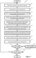
- FIG. 7 conceptually illustrates a process of some embodiments for performing analysis to identify compromised DCNs.
- FIG. 8 conceptually illustrates a table with different metrics for two different VMs giving rise to different scores.
- FIG. 9 conceptually illustrates an electronic system with which some embodiments of the invention are implemented.
- Some embodiments provide an analysis appliance that automatically detects security threats (e.g., compromised data compute nodes (DCNs)) in a datacenter based on analysis of name resolution responses in the datacenter.
- the analysis appliance of some embodiments receives flow attribute sets from host computers in the datacenter (on which the DCNs execute) and identifies flow attribute sets that correspond to DCNs responding to name resolution requests. For each DCN of at least of a set of DCNs in the datacenter, the analysis appliance analyzes the name resolution responses sent by the DCN to determine a likelihood that the DCN has been compromised and is maliciously responding to these name resolution requests in order to gain authentication information of other DCNs in the datacenter.
- the analysis appliance can initiate remediation actions (e.g., quarantine, etc.) of the compromised DCN.
- some embodiments leverage a data flow collection system for the datacenter that collects and reports attributes of data flows associated with the DCNs executing in the datacenter (e.g., virtual machines (VMs), containers, bare metal computing devices, etc.).
- Agents on host computers collect and export data flow information for the data compute nodes (DCNs) to the analysis appliance (which may operate, e.g., as a single server or cluster of servers).
- Agents on the host computers e.g., different agents than those that export the data flow information
- FIG. 1 conceptually illustrates the analysis appliance 100 of some embodiments, as well as the network managers 107 and host computers 105 .
- the analysis appliance 100 includes a processing pipeline 110 for flow data (e.g., flow attribute sets received from host computers), a set of data storages 120 for storing received data, a set of real-time anomaly detectors 150 for performing regular anomaly detection on incoming flow data from the processing pipeline 110 , and a set of data processing engines 130 (e.g., a visualization engine 131 , a name resolution response analysis engine 132 , and other engines 133 ).
- flow data e.g., flow attribute sets received from host computers
- data storages 120 for storing received data
- a set of real-time anomaly detectors 150 for performing regular anomaly detection on incoming flow data from the processing pipeline 110
- a set of data processing engines 130 e.g., a visualization engine 131 , a name resolution response analysis engine 132 , and other engines 133 .
- the host computers 105 will be described in greater detail below by reference to FIG. 2 . As shown, these host computers execute one or more DCNs 155 (e.g., virtual machines (VMs), containers, etc.) that can run services, applications, etc. These DCNs 155 send and receive data traffic, which are organized as data message flows. Each host computer 105 also executes (e.g., within virtualization software) a context exporter 160 and a flow exporter 165 , which are associated with the analysis appliance 100 .
- the context exporter 160 collects context data regarding the DCNs 155 and provides this data to the analysis appliance 100 .
- the flow exporter 165 collects information about data flows to and from the DCNs 155 and provides this data to the analysis appliance 100 .
- the network managers 107 provide configuration data to the analysis appliance 100 , including management plane configuration data and policy configuration data.
- the analysis appliance 100 communicates control messages (e.g., updates to service rule policies, updated keys, updated group memberships validated by a user, etc.) through the network managers 107 .
- control messages e.g., updates to service rule policies, updated keys, updated group memberships validated by a user, etc.
- a user e.g., an administrator, not shown
- can interact with the analysis appliance 100 directly e.g., to provide commands to the visualization engine 131 ).
- the processing pipeline 110 processes flow data (e.g., flow attribute sets, also referred to as flow group records) received from the host computers in the system for analysis by other elements of the appliance (e.g., the anomaly detector 150 ).
- flow data e.g., flow attribute sets, also referred to as flow group records
- the processing pipeline 110 deduplicates these flow attribute sets (i.e., into a single flow attribute set). This deduplication process matches these flows (e.g., based on flow keys) and, in some embodiments, generates a new flow attribute set for the data flow that includes all unique attributes from both the source and destination host computer flow attribute sets.
- the processing pipeline 110 stores these flow attribute sets in the data storages 120 (e.g., the flow group records 121 ). In some embodiments, in addition to deduplication, the processing pipeline 110 also identifies and groups corresponding flow attribute sets (e.g., for reverse direction flows, or otherwise-related flows). These flow attribute sets are also combined and stored in, e.g., the flow group records 121 .
- the processing pipeline 110 of some embodiments also fills in missing information for flow attribute sets, if needed (e.g., DCN identifiers for remote DCNs, etc.) using other flow attribute sets or other information (e.g., by matching DCN identifiers to network addresses already present in the flow attribute sets). Correlation of flow attribute sets can again be performed after this missing information is filled in. Additional description of the processing pipeline 110 is found in U.S. patent application Ser. No. 16/520,220, now issued as U.S. Pat. No. 11,398,897, which is incorporated herein by reference.
- the data storages 120 include, in some embodiments, a data storage for each different type of data received (e.g., a correlated flow group record data storage 121 , a contextual attribute data storage 122 , a configuration data storage 123 , and a time series data storage 124 ).
- the contextual attribute data storage 122 stores received contextual attribute data from multiple host computers and uses that data for populating the time series data storage 124 with contextual attribute data (e.g., in a contextual attribute topic).
- the contextual attribute data storage 122 is used in correlating contextual attributes with flow group records for display.
- the time series data storage 124 is used additionally, or alternatively, in other embodiments, for correlating contextual attribute data to flow group record data.
- the contextual attribute data storage 122 receives contextual attribute data sets including any, or all, of: data regarding guest metadata, guest events, and guest DCN metrics.
- the guest metadata includes any or all of DCN details (a universally unique identifier [uuid], a bios uuid and a vmxpath), operating system details (type of OS and version information), and process details (e.g., process ID, creation time, hash, name, command line, security ID [sid], user ID [uid], loaded library or module information, process metrics [e.g., memory usage and CPU usage], process version, parent process ID, etc.).
- DCN details a universally unique identifier [uuid], a bios uuid and a vmxpath
- operating system details type of OS and version information
- process details e.g., process ID, creation time, hash, name, command line, security ID [sid], user ID [uid], loaded library or module information, process metrics [e.
- Guest events include DCN events (e.g., power on and power off), user login events (e.g., login, logoff, connect, and disconnect events, a session ID, a timestamp, a DCN IP, and a connected client IP), and service process events (e.g., event type [e.g., listen start, listen stop], timestamp, destination DCN IP, destination port number, and process details).
- Guest DCN metrics include memory usage and CPU usage. It should be understood that many additional pieces of information may be provided to a contextual attribute data storage and that the partial list above serves only as an example.
- the set of data storages 120 includes a flow group record data storage 121 .
- this data storage 121 stores flow attribute sets after aggregation and correlation with configuration data stored in the configuration data storage 123 .
- the flow group record data storage 121 also stores learned pairings of IP addresses and DCN identifiers. In some embodiments, the learning is based on previously processed flow record groups.
- the correlated flow group record data storage 121 in some embodiments, provides processed (e.g., aggregated and correlated) flow group records to the time series data storage.
- the configuration data storage 123 receives configuration data (e.g., management plane configuration and/or policy configuration) from a network manager controller.
- the management plane configuration data includes information relating to group membership (in terms of DCN), and the policy configuration data sets include information about service rules (e.g., firewall rules), in some embodiments.
- the service rules in some embodiments, are expressed in terms of any of IP addresses, ports, protocols, groups, etc., in any combination.
- an initial set of configuration data is sent at startup or reboot of either the network manager computer or the analysis appliance, while subsequent configuration data sets include only changes to the last configuration data set.
- a time series data storage 124 stores flow group records, configuration data, and context data.
- the time series data storage 124 is organized by topic with each different type of data stored in a different topic. Additionally, in some embodiments, each topic is organized in a time series fashion by use of an index that is appended to each set of data and is coordinated among all the producers of data for the topic.
- the time series data storage 124 is organized at multiple levels of temporal granularity, in some embodiments. In some embodiments, the different levels of granularity include some combination of hourly, daily, weekly, and monthly.
- the different levels of temporal granularity are used, in some embodiments, for data collected for a previous 24 hours (e.g., organized on an hourly basis), data for a previous 6 days (e.g., organized on a daily basis), data for a previous 30 days (e.g., organized on a daily or weekly basis), and data received more than 30 days earlier (e.g., organized on a monthly basis).
- the data organized based on the various levels of temporal granularity are, in some embodiments, periodically (e.g., daily, hourly, etc.) rolled up into the next level of granularity.
- Real-time (or near-real-time) anomaly detectors 150 analyze the correlated flow attribute sets as this flow information is received and correlated by the processing pipeline 110 (as opposed to retrieving data from the storages 120 ).
- the processing pipeline 110 provides the flow information (possibly also correlated to contextual attribute information) to the real-time anomaly detectors 150 as batches of flow attribute sets are correlated and processed.
- These anomaly detectors 150 detect various types of anomalies (e.g., port sweeps, suspicious network connections, etc.) and store records of each detected anomalous event in an anomaly storage (e.g., a database, not shown in the figure).
- each record of an anomalous event indicates at least a start and end time for the event, one or more associated DCNs, and a description of the event.
- the anomaly detectors 150 also provide at least a subset of the anomalous event records (e.g., records for particular types of anomalous events) directly to the data processing engines 150 .
- the data processing engines 130 include a name resolution response analysis engine 131 and a set of other engines 133 .
- these various data processing engines 130 analyze the time series data 124 at regular intervals (e.g., every 10 minutes, every 30 minutes, every hour, etc.) to perform various types of analysis for the datacenter (e.g., to detect various types of anomalous events in the datacenter network). For instance, anomaly detectors might look for anomalous amounts of dropped traffic, the presence of malicious files on a DCN, vertical port scans, password and/or hash collection taking place on a DCN, etc.
- the name resolution response analysis engine 131 is one example of such an anomaly detector in some embodiments.
- the name resolution response analysis engine 131 identifies flow attribute sets representing name resolution response flows within the datacenter and analyzes these flows to determine whether any DCNs appear to be compromised (and are therefore using the response flows to attempt to gain authentication information from benign DCNs in the datacenter.
- the other engines 133 perform various other tasks, including generation of a graphical user interface through which an administrator can interact with and control the analysis appliance 100 and additional processing of anomalous events.
- the graphical user interface of some embodiments provides information about DCNs, flows, contextual attributes, anomalous events, etc.
- the name resolution response analysis engine 131 as well as some of the other engines 133 can also initiate communication with the network managers 107 in some embodiments (e.g., to specify firewall rules that should be configured in the datacenter network). Additional information about the analysis appliance 100 can be found in U.S. Patent Publication 2021/0029050, which is incorporated by reference herein.
- FIG. 2 conceptually illustrates a host computer 200 (e.g., one of the host computers 105 ) of some embodiments in more detail, specifically focusing on the context exporter 240 and flow exporter 270 that collect, aggregate, and publish aggregated data to the analysis appliance.
- the host computer 200 also executes several data compute nodes (DCNs) 205 , a set of service engines 215 , a threat detector/deep packet inspection (DPI) module 232 , a set of third-party processes 233 , a MUX (multiplexer) 227 , an anomaly detector 222 , a machine learning (ML) engine 224 , and a software forwarding element 212 .
- DCNs data compute nodes
- DPI threat detector/deep packet inspection
- MUX multiplexer
- an anomaly detector 222 e.g., a machine learning (ML) engine 224
- ML machine learning
- Guest introspection agents 250 execute on the DCNs 205 and extract context data from the DCNs 205 .
- a guest introspection agent 250 detects that a new data flow has been initiated (e.g., by sending a SYN packet in a data flow using TCP) and collects introspection data (e.g., a set of attributes of the data flow and DCN).
- the introspection data includes any, or all, of data regarding (i) guest metadata, (ii) guest events, and (iii) guest DCN metrics.
- the guest metadata includes any, or all, of data regarding DCN 205 (a universally unique identifier [uuid], a bios uuid, and a vmxpath), operating system data (type of OS and version information), and process data (e.g., process ID, creation time, hash, name, command line, security ID [sid], user ID [uid], loaded library or module information, process metrics [e.g., memory usage and CPU usage], process version, parent process ID, etc.).
- DCN 205 a universally unique identifier [uuid], a bios uuid, and a vmxpath
- operating system data type of OS and version information
- process data e.g., process ID, creation time, hash, name, command line, security ID [sid], user ID [uid], loaded library or module information, process metrics [e.g., memory usage and CPU usage], process version, parent process ID, etc.
- Guest events include DCN events (e.g., power on and power off), user login events (e.g., login, logoff, connect, and disconnect events, a session ID, a timestamp, a DCN IP, and a connected client IP), and service process events (e.g., event type [e.g., listen start, listen stop], timestamp, destination DCN IP, destination port number, and process details).
- Guest DCN metrics include memory usage and CPU usage. It should be understood that much of the context data, in some embodiments, is not included in L 2 -L 7 headers of a flow and that many additional pieces of information may be collected by guest introspection agent 250 . The partial list above serves only as an example of the types of information that can be gathered by guest introspection agent 250 .
- the guest introspection agents 250 send the collected context information to the context exporter 240 (specifically to the context engine 210 ) through a multiplexer 227 .
- the context exporter 240 includes the context engine 210 , a contextual attribute storage 245 , a context publisher timer 246 , and a context publisher 247 .
- the context exporter 240 processes context data (e.g., contextual attribute data sets) at the host computer 200 and publishes the context data to the analysis appliance.
- the context engine 210 also provides the received context information to other elements operating in the host computer 200 and correlates this context data with context data received from other sources.
- the other sources include the set of service engines 215 , the threat detector/DPI module 232 , third-party software (processes) 233 , the anomaly detector 222 , and the ML engine 224 .
- the context engine 210 correlates the context data from the multiple sources for providing the correlated context data (e.g., sets of correlated contextual attributes) to the context publisher 247 (e.g., through context attribute storage 245 ).
- each DCN 205 also includes a virtual network interface controller (VNIC) 255 in some embodiments.
- VNIC virtual network interface controller
- Each VNIC is responsible for exchanging messages between its respective DCN and the SFE 212 (which may be, e.g., a virtual switch or a set of virtual switches).
- Each VNIC 255 connects to a particular port 260 - 265 of the SFE 212 .
- the SFE 212 also connects to a physical network interface controller (PNIC) (not shown) of the host.
- PNIC physical network interface controller
- the VNICs are software abstractions of one or more physical NICs (PNICs) of the host created by the virtualization software of the host (within which the software forwarding element 212 executes).
- the SFE 212 maintains a single port 260 - 265 for each VNIC of each DCN.
- the SFE 212 connects to the host PNIC (through a NIC driver [not shown]) to send outgoing messages and to receive incoming messages.
- the SFE 212 is defined to include one or more ports that connect to the PNIC driver to send and receive messages to and from the PNIC.
- the SFE 212 performs message-processing operations to forward messages that it receives on one of its ports to another one of its ports.
- the SFE 212 tries to use data in the message (e.g., data in the message header) to match a message to flow-based rules, and upon finding a match, to perform the action specified by the matching rule (e.g., to hand the message to one of its ports, which directs the message to be supplied to a destination DCN or to the PNIC).
- data in the message e.g., data in the message header
- flow-based rules e.g., a message to flow-based rules
- the action specified by the matching rule e.g., to hand the message to one of its ports, which directs the message to be supplied to a destination DCN or to the PNIC.
- the SFE 212 is a software switch (e.g., a virtual switch), while in other embodiments it is a software router or a combined software switch/router, and may represent multiple SFEs (e.g., a combination of virtual switches and virtual routers).
- the SFE 212 implements one or more logical forwarding elements (e.g., logical switches or logical routers) with SFEs 212 executing on other hosts in a multi-host environment.
- a logical forwarding element in some embodiments, can span multiple hosts to connect DCNs that execute on different hosts but belong to one logical network.
- Different logical forwarding elements can be defined to specify different logical networks for different users, and each logical forwarding element can be defined by multiple software forwarding elements on multiple hosts. Each logical forwarding element isolates the traffic of the DCNs of one logical network from the DCNs of another logical network that is serviced by another logical forwarding element.
- a logical forwarding element can connect DCNs executing on the same host and/or different hosts, both within a datacenter and across datacenters.
- the SFE 212 extracts from a data message a logical network identifier (e.g., a VNI) and a MAC address. The SFE 212 , in such embodiments, uses the extracted VNI to identify a logical port group or logical switch, and then uses the MAC address to identify a port within the port group or logical switch.
- a logical network identifier e.g., a VNI
- the ports of the SFE 212 include one or more function calls to one or more modules that implement special input/output (I/O) operations on incoming and outgoing messages that are received at the ports 260 - 265 .
- I/O operations that are implemented by the ports 260 - 265 include ARP broadcast suppression operations and DHCP broadcast suppression operations, as described in U.S. Pat. No. 9,548,965.
- Other I/O operations (such as firewall operations, load-balancing operations, network address translation operations, etc.) can be so implemented in some embodiments of the invention.
- the ports 260 - 265 can implement a chain of I/O operations on incoming and/or outgoing messages in some embodiments.
- other modules in the data path implement the I/O function call operations instead of, or in conjunction with, the ports 260 - 265 .
- one or more of the function calls made by the SFE ports 260 - 265 can be to service engines 215 , which query the context engine 210 for context information that the service engines 215 use (e.g., to generate context headers that include context used in providing a service and to identify service rules applied to provide the service).
- the generated context headers are then provided through the port 260 - 265 of SFE 212 to flow exporter 270 (e.g., flow identifier and statistics collector 271 ).
- the service engines 215 can include a distributed firewall engine of some embodiments that implements distributed firewall rules configured for the datacenter network. These distributed firewall rules are, in some embodiments, defined in terms of rule identifiers, and specify whether to drop or allow traffic from one group of DCNs to another group of DCNs.
- the firewall rules can be specified in terms of source and destination network addresses (e.g., IP and/or MAC addresses) and/or security groups (which are converted to network addresses). For instance, a firewall rule might be defined at the network manager level as allowing any traffic from a set of web server VMs running the Linux operating system (a first security group) to a set of database server VMs running the Windows operating system (a second security group). This firewall rule is then translated into a set of more specific rules based on the membership of the DCNs in the first and second security groups using the IP and/or MAC addresses of these DCNs.
- the flow exporter 270 monitors flows, collects flow data and statistics, aggregates flow data into flow group records, and publishes flow attribute sets (also referred to as flow group records) for consumption by the analysis appliance.
- the flow exporter 270 generally aggregates statistics for individual flows identified during multiple time periods, and for each time period identifies multiple groups of flows with each group including one or more individual flows.
- the flow exporter 270 identifies a set of attributes by aggregating one or more subsets of attributes of one or more individual flows in the group as described below in greater detail.
- the subset of attributes of each individual flow in each group is the aggregated statistics of the individual flow.
- flow exporter 270 provides the set of attributes for each group identified in the multiple time periods to the analysis appliance for further analysis of the identified flows.
- the flow exporter 270 includes a flow identifier/statistics collector 271 , a flow identifier and statistics storage 272 , a flow collector timer 273 , a flow collector 274 , a first-in first-out (FIFO) storage 275 , a configuration data storage 276 , a flow aggregator 277 , a flow group record storage 278 , a flow publisher timer 279 , and a flow group record publisher 280 .
- These modules collectively collect and process flow data to produce and publish flow attribute sets.
- the flow exporter 270 receives flow information, including flow identifiers and statistics, at the flow identifier/statistics collector 271 .
- the received flow information is derived from individual data messages that make up the flow and includes context data used in making service decisions at service engines 215 .
- the flow information also specifies which firewall rules are applied to each flow (e.g., using firewall rule identifiers).
- the flow exporter 270 stores the received information associated with particular flows in the flow identifier and statistics storage 272 .
- the statistics in some embodiments, are summarized (accumulated) over the life of the particular flow (e.g., bytes exchanged, number of packets, start time, and duration of the flow).
- the flow collector 274 monitors the flows to determine which flows have terminated (e.g., timeouts, FIN packets, RST packets, etc.) and collects the flow identifiers and statistics and pushes the collected data to FIFO storage 275 .
- the flow collector 274 collects additional configuration data from configuration data storage 276 and includes this additional configuration data with the data collected from flow identifier and statistics storage 272 before sending the data to FIFO storage 275 .
- the flow collector 274 collects data for long-lived active flows (e.g., flows lasting longer than half a publishing period) from the flow identifier and statistics storage 272 before the end of a publishing period provided by flow publisher timer 279 .
- the data collected for a long-lived active flow is different from the data collected for terminated flows. For example, active flows are reported using a start time but without a duration in some embodiments. Some embodiments also include flows that are initiated but dropped/blocked based on firewall rules.
- Only flows meeting certain criteria are collected by the flow collector 274 in some embodiments. For example, only information for flows using a pre-specified set of transport layer protocols (e.g., TCP, UDP, ESP, GRE, SCTP) are collected, while others are dropped or ignored.
- the FIFO storage 275 is a circular or ring buffer such that only a certain number of sets of flow identifiers and flow statistics can be stored before old sets are overwritten.
- the flow aggregator 277 pulls data stored in FIFO storage 275 based on a flow collection timer 273 and aggregates the pulled data into aggregated flow group records.
- Some embodiments pull data from the FIFO storage 275 based on a configurable periodicity (e.g., every 10 seconds), while other embodiments, alternatively or in addition to the periodic collection, dynamically determine when to collect data from FIFO storage 275 based on a detected number of data flows (e.g., terminated data flows, a total number of active data flows, etc.) and the size of FIFO storage 275 .
- a detected number of data flows e.g., terminated data flows, a total number of active data flows, etc.
- Each set of flow data pulled from FIFO storage 275 for a particular flow in some embodiments, represents a unidirectional flow from a first endpoint (e.g., machine or DCN) to a second endpoint.
- a same unidirectional flow is captured at different ports 260 - 265 of the software forwarding element 212 .
- the flow identifier 271 uses a sequence number or other unique identifier to determine if the data message has been accounted for in the statistics collected for the flow.
- the flow aggregator 277 additionally combines sets of flow data received for the separate unidirectional flows into a single set of flow data in some embodiments. This deduplication (deduping) of flow data occurs before further aggregation in some embodiments and, in other embodiments, occurs after an aggregation operation.
- the flow aggregator 277 receives a set of keys from the analysis appliance through the network manager computer that specify how the flow data sets are aggregated. After aggregating the flows, the flow aggregator 277 performs a deduplication process to combine aggregated flow group records for two unidirectional flows between two DCNs 205 executing on host machine 200 into a single aggregated flow group record and stores the aggregated records in flow group record storage 278 . From flow group record storage 278 , flow group record publisher 280 publishes the aggregated flow group records to an analysis appliance according to a configurable timing provided by flow publisher timer 279 . After publishing the aggregated flow group records (and, in some embodiments, receiving confirmation that the records were received), the records stored for the previous publishing time period are deleted and a new set of aggregated flow group records are generated.
- one of the flow aggregator 277 and the context engine 210 performs another correlation operation to associate the sets of correlated contextual attributes stored in contextual attribute storage 245 with the aggregated flow group records stored in the flow group record storage 278 .
- the correlation includes generating new flow attribute sets with additional attribute data included in existing attribute fields or appended in new attribute fields.
- the sets of correlated contextual attributes and aggregated flow group records are tagged to identify related sets of aggregated flow group records and contextual attribute data.
- the generated new flow group records are published from one of the publishers (e.g., flow group record publisher 280 or context publisher 247 ).
- flow group record publisher 280 publishes the tagged aggregated flow group records and the context publisher 247 publishes the tagged sets of correlated contextual attributes.
- the anomaly detection engine 222 receives flow data (from any of flow identifier and statistics storage 272 , FIFO storage 275 , or flow group record storage 278 ) and context data from context engine 210 and detects, based on the received data, anomalous behavior associated with the flows. For example, based on context data identifying the application or process associated with a flow, anomaly detection engine 222 determines that the source port is not the expected source port and is flagged as anomalous.
- the detection in some embodiments, includes stateful detection, stateless detection, or a combination of both. Stateless detection does not rely on previously collected data at the host, while stateful detection, in some embodiments, maintains state data related to flows and uses the state data to detect anomalous behavior.
- a value for a mean round trip time (RTT) or other attribute of a flow and a standard deviation for that attribute may be maintained by anomaly detection engine 222 and compared to values received in a current set of flow data to determine that the value deviates from the mean value by a certain number of standard deviations that indicates an anomaly.
- anomaly detection engine 222 appends a field to the set of context data that is one of a flag bit that indicates that an anomaly was detected or an anomaly identifier field that indicates the type of anomaly detected (e.g., a change in the status of a flow from allowed to blocked [or vice versa], a sloppy or incomplete TCP header, an application/port mismatch, or an insecure version of an application).
- the additional context data is provided to context engine 210 separately to be correlated with the other context data received at context engine 210 .
- the anomaly detection process may use contextual attributes not in L 2 -L 4 headers such as data included in L 7 headers and additional context values not found in headers.
- the anomaly detection engine 222 takes an action or generates a suggestion based on detecting the anomaly. For example, anomaly detection engine 222 can block an anomalous flow pending user review or suggest that a new firewall rule be added to a firewall configuration. In some embodiments, the anomaly detection engines 222 on each host computer 200 can report these anomalies (e.g., via the context publisher 247 ) to the analysis appliance for further analysis by the anomaly processing engine.
- the machine learning engine 224 receives flow data (from any of the flow identifier and statistics storage 272 , the FIFO storage 275 , and the flow group record storage 278 ) and context data from the context engine 210 and performs analysis on the received data.
- the received data e.g., flow group records
- the analysis identifies possible groupings of DCNs 205 executing on the host computer 200 .
- the analysis is part of a distributed machine learning process, and the results are provided to the context engine 210 as an additional contextual attribute.
- FIG. 3 conceptually illustrates additional details of the name resolution response analysis engine 131 of the analysis appliance 100 of some embodiments.
- the name resolution response analysis engine 131 includes a baseline calculator 305 , a response flow identifier 310 , an analysis and scoring module 315 , and a remediation module 320 .
- the name resolution response analysis engine 131 stores baseline metrics 325 that are calculated by the baseline calculator 305 .
- the name resolution response analysis engine 131 receives batches of flow attribute sets. These can include flow attribute sets from the last 30 days (or a similar baseline time period) for use by the baseline calculator 305 as well as flow attribute sets from only the current day (or current hour, etc., depending on the time period used for performing the analysis).
- the response flow identifier 310 analyzes the flow attribute sets received by the name resolution response analysis engine 131 to identify flow attribute sets corresponding to name resolution responses. As described further below, in some embodiments this entails examining the flow attribute sets for flows having specific destination addresses and/or destination port numbers in order to find name resolution requests, and then searching for any name resolution responses sent in response to these requests. The response flow identifier 310 identifies these name resolution response flows both for the baseline time period as well as for the current time period (using similar methodologies on different groups of flow attribute sets at different time). The response flow identifier 310 provides the response flow information for the baseline time period to the baseline calculator 305 and for the current time period to the analysis and scoring module 315 .
- the baseline calculator 305 calculates baseline metrics 325 for each DCN of at least a set of DCNs operating in the datacenter and stores these baseline metrics for use in subsequent analysis. In some embodiments, these baseline metrics 325 are calculated over a baseline period (e.g., the previous 30 days) based on the response flow information identified by the response flow identifier 310 , and the set of DCNs for which baseline metrics are calculated includes only those DCNs that have been operating for the entire baseline period. In other embodiments, the baseline calculator 305 also calculates baseline metrics for DCNs that have been operating for less than the baseline time period (e.g., any DCN operating for at least 3 days).
- the baseline metrics 325 can include various metrics.
- the baseline calculator 305 of some embodiments calculates averages over the baseline period (e.g., a daily average over a 30-day baseline period) of the number of name resolution responses each DCN sent per time period (e.g., per day) and the number of unique DCNs to which each DCN sent name resolution responses per time period.
- the baseline calculator 305 of some embodiments also calculates, for each DCN, the ratio of name resolution responses sent to name resolution requests received during the baseline time period.
- the baseline calculator 305 generates lists, for each DCN of (i) all of the DCNs to which the DCN sent name resolution responses during the baseline time period and (ii) all of the names for which the DCN sent name resolution responses during the baseline time period.
- the analysis and scoring module 315 performs the analysis to compare name resolution response flow information for the current time period (e.g., the current day) to the previously-calculated baseline metrics in order to identify potentially compromised DCNs in the datacenter.
- the analysis and scoring module 315 compares (for each DCN) the number of name resolution responses sent during the current time period to the baseline average number of name resolution responses sent during such a time period within the baseline time period (e.g., the number of responses sent during the current day compared to the average number sent per day), the ratio of name resolution responses sent to name resolution requests received during the current time period to the equivalent ratio during the baseline time period, and the number of unique DCNs to which name resolution responses were sent during the current time period to the number of unique DCNs to which name resolution responses were sent during the baseline time period.
- the analysis and scoring module also, in some embodiments, identifies the number of new DCNs to which the DCN sent name resolution responses during the current time period and the number of new names for which the DCN sent name resolution responses during the current time period (i.e., DCNs and names that were not on the baseline lists for the DCN). Based on these various metrics, and possibly incorporating any other anomalous events received from the anomaly detectors 150 , the analysis and scoring module 315 generates a score for each DCN indicating the likelihood that the DCN is compromised. Scores above a threshold indicate that the DCN is likely compromised, and the remediation module 320 is informed of the DCNs and their scores.
- the remediation module 320 initiates remediation actions (e.g., by communicating with the network manager(s) 107 ).
- higher scores result in more aggressive remediation actions. For instance, for a first tier of potential threats (e.g., DCNs having scores above a first threshold), the remediation module generates and provides to the network managers 107 firewall rules that prevent the DCNs from receiving name resolution requests. For a second tier of such potential threats (e.g., DCNs having scores above a higher second threshold), the remediation module generates and provides to the network managers 107 firewall rules that more fully quarantine the DCNs by, e.g., preventing the DCNs from sending and/or receiving any network traffic or setting up any network connections.
- the name resolution response analysis engine of some embodiments identifies flow attribute sets corresponding to name resolution responses (i.e., responses to name resolution requests) sent by DCNs within the datacenter network, then uses these identified flow attribute sets to perform its analysis.
- FIG. 4 conceptually illustrates a process 400 of some embodiments for identifying flow attribute sets corresponding to name resolution response flows.
- the process 400 is performed by the response flow identifier 310 upon receiving a batch of flow attribute sets from the time series database (or processing pipeline) of the analysis appliance.
- the process 400 begins by receiving (at 405 ) a batch of processed and aggregated flow attribute sets.
- these flow attribute sets are retrieved from the time series database and may have been collected during a particular time period. If the name resolution response analysis engine is currently generating baseline metrics (e.g., at the beginning of a day, to calculate new metrics for the most recent 30-day period), then the flow attribute sets were collected during the baseline time period. If baseline metrics have already been calculated and the name resolution response analysis engine is currently calculating threat likelihood scores, then the flow attribute sets were collected during the current time period for analysis (e.g., the current day).
- Each flow attribute set indicates at least source and destination network addresses (e.g., IP addresses), a transport layer protocol, and source and destination transport layer port numbers, information which can be used to identify the name resolution request and response flows.
- source and destination network addresses e.g., IP addresses
- transport layer protocol e.g., IP addresses
- source and destination transport layer port numbers e.g., IP addresses
- information which can be used to identify the name resolution request and response flows e.g., IP addresses
- transport layer protocol e.g., IP addresses
- source and destination transport layer port numbers e.g., information which can be used to identify the name resolution request and response flows.
- LLMNR request flows are user datagram protocol (UDP) flows, (ii) are addressed to the same multicast IP address ( 224 . 0 . 0 . 252 ), and (iii) have the same destination transport layer port ( 5355 ).
- NBT-NS request flows (i) are also UDP flows, (ii) are addressed to a multicast IP address (e.g., 192.168.1.255), and (iii) have the same destination transport layer port ( 137 ).
- any flows that match either of these sets of criteria can be identified as name resolution request flows.
- the process 400 identifies any name resolution response flows. Because the name resolution requests are sent out as multicast messages (on a physical network or a logical network), the requesting DCN may receive name resolution responses from multiple responder DCNs. In general, the requesting DCN uses the first response received. LLMNR response flows typically are (i) UDP flows, (ii) are sent to a destination network address that matches the source network address of the identified request flow, and (iii) have a destination port number that matches the source port number of the identified request flow. In addition, of course, the response flow should have a timestamp from a short time after the request flow. FIG.
- the request flow 505 is a UDP flow with a source IP address of 192.168.1.8, a source port of 56947 , a destination IP address of 224.0.0.252, and a destination port of 5355 . Based on the protocol, destination IP address, and destination port, this can be identified as a name resolution request flow.
- Each of the response flows 510 and 515 are UDP flows with destination IP addresses of 192.168.1.8 and destination ports of 56947 , matching the source IP address and source port of the request flow, so they are each identified as name resolution response flows.
- the two response flows are sent from different source IP addresses and use different source ports (the source port on the responses can be ignored, in some embodiments).
- NBT-NS response flows typically are (i) UDP flows, (ii) are sent to a destination network address that matches the source network address of the identified request flow, and (iii) have the same destination port number ( 137 , the same port number used for request flows).
- FIG. 6 conceptually illustrates an example of an NBT-NS request flow 605 and a corresponding NBT-NS response flow 610 .
- the request flow 605 is a UDP flow with a source IP address of 192.168.1.8, a source port of 25, a destination IP address of 192.168.1.255, and a destination port of 137 . Based on the protocol, destination IP address, and destination port, this can be identified as a name resolution request flow.
- the response flow 610 is a UDP flow with a destination IP address of 192.168.1.8 (matching the source IP address of the request flow) and a destination port of 137 (the port used for all NBT-NS requests and responses), so this is identified as a name resolution response flow.
- the source port for both messages can be ignored for NBT-NS messages in some embodiments.
- the process 400 maps (at 420 ) each of the identified name resolution response flows to a responding DCN.
- the name resolution response analysis engine uses the source IP address of the response flow to identify the responder DCN.
- the analysis appliance performs this analysis as part of the flow attribute set aggregation and processing prior to storing the flow attribute sets in the time series database (which can be necessary when a datacenter includes many logical networks with overlapping network addresses spaces).
- the flow attribute set specifies a source DCN for the flow (e.g., using a unique (to the datacenter) identifier for the DCN.
- the name resolution response analysis engine just aggregates the response flows by responder DCN.
- the name resolution response analysis engine of some embodiments analyzes each DCN of at least a subset of DCNs in a datacenter on a regular basis to determine the likelihood that the DCN has been compromised and is attempting to capture authentication information by spoofing name resolution responses.
- FIG. 7 conceptually illustrates a process 700 of some embodiments for performing analysis to identify compromised DCNs.
- the name resolution response analysis engine performs the process 700 or a similar process on a regular basis (e.g., every 10 minutes). In datacenters where name resolution protocols are more widely used, this regular time can be decreased so that the threats are detected more quickly.
- the process 700 begins (at 705 ) by selecting a DCN to analyze as a name resolution responder.
- the DCNs are analyzed based on how often they respond to name resolution requests; how often the DCNs initiate such requests is not of concern because these requests are typically benign.
- the process 700 is a conceptual process that performs analysis on each DCN serially.
- the name resolution response analysis engine of some embodiments actually performs analysis on many DCNs in parallel (e.g., performing the operations of the process 700 in parallel for each of these DCNs).
- the process 700 identifies (at 710 ) baseline metrics for the selected DCN.
- the baseline metrics for each DCN to be analyzed are calculated at the beginning of a time period and stored until they need to be updated. For instance, if a 30-day baseline period is used and this changes each day, then the baseline metrics are recalculated at the beginning of each day and stored for the entire day. The same baseline metrics are then used each time the name resolution response analysis engine performs its analysis (e.g., every 10 minutes).
- the process 700 performs a number of comparisons of the current time period metrics to the baseline metrics. It should be understood that, while the process 700 shows a specific set of comparisons being performed in a particular order, other embodiments may perform the comparisons in a different order, may perform fewer, additional, or different comparisons, may perform the comparisons in parallel, etc. Each of the metrics has both upsides and downsides, and thus the combination of metrics is used to arrive at a score.
- the process 700 uses the current day as the current time period, but the current time period could be a different length of time period in other embodiments (e.g., the current week, current hour, etc.). In the case of a different time period length, the baseline averages would be averaged over equivalent time periods (e.g., for a current time period of the current hour, an hourly average from the past 24 or 48 hours might be used instead of a 30-day daily average).
- the process 700 compares (at 715 ) the number of name resolution responses sent during the current day to the baseline running average of responses sent per day for the DCN.
- an increase in the overall number of name resolution responses sent compared to the average can potentially be indicative of anomalous behavior.
- an increase in the number of responses sent by a DCN could just be due to an increase in the number of requests received by the DCN.
- the process 700 also compares (at 720 ) the ratio of name resolution responses sent to name resolution requests received during the current day to the equivalent ratio over the baseline time period. This will generally have fewer false positives than the first metric, because it does not depend on the number of name resolution requests any given DCN receives. However, the ratio could still vary based on which DCNs are sending the name resolution requests and for which names the requests are sent during the current time period.
- the process 700 also compares (at 725 ) the number of unique DCNs to which the selected DCN responded during the current day to the average number of unique DCNs to which the selected DCN responded during the baseline period.
- This comparison provides additional context in that a selected DCN might be responding to more of the received name resolution requests than usual because a particular DCN to which it usually responds has sent out a larger than usual number of requests. However, if the selected DCN receives requests from a larger than usual number of DCNs, then this comparison could be skewed to produce a false positive without additional context.
- the process 700 also determines (at 730 ) the number of unique DCNs to which the selected DCN sent a name resolution response during the current day that are not on the list of DCNs to which the selected DCN responded during the baseline period.
- Responding to new DCNs is a good sign that the selected DCN is compromised, as a compromised DCN will often try to respond to as many name resolution requests as possible in order to collect authentication information from those DCNs.
- a new DCN sends a name resolution request, that could create a false positive.
- the selected DCN regularly responds to all of the DCNs in its multicast group, this will not pick up the DCN being compromised.
- the process 700 of some embodiments determines (at 735 ) the number of new names for which the selected DCN has sent a name resolution response during the current day that are not on a list of names for which the selected DCN sent any responses during the baseline period. Using this metric helps avoid false positives due to large numbers of requests for a single name for which the selected DCN has commonly sent name resolution responses. However, if the naming scheme in the subnet to which the selected DCN belongs, this can still create false positives. Furthermore, using this metric requires additional processing either at the host computers or by the analysis appliance in order to identify this information from the name resolution request and/or response messages.
- the process 700 also identifies (at 740 ) any additional anomalies related to the selected DCN.
- other anomaly detectors within the analysis appliance perform real-time and/or batch processing to detect various different types of anomalies, some of which can be useful in detecting a name resolution response attack. For instance, some embodiments model an outgoing connection pattern for each DCN and use this to identify anomalous outgoing connections. While this does not on its own indicate a name resolution response attack, it can be used in combination with the other metrics to strengthen the case that the DCN is compromised.
- the process 700 computes (at 745 ) a threat likelihood score for the selected DCN.
- the threat likelihood score computation for a DCN is based on different combinations of the various metrics analyzed for the DCN. For instance, some embodiments use a weighted computation that assigns a normalized score for each metric and computes a weighted sum of the normalized scores. The metrics measuring deviation from an average might be scored in terms of number of standard deviations above the average, while the metrics measuring unique new DCNs to which the selected DCN responds or unique new names for which responses are sent might be scored based on an absolute number of new DCNs or names.
- the weighted sum allows for metrics to be assigned more importance than others (e.g., responding to a new unique name might be considered more important than the change in response to request ratio).
- specific combinations can be multiplicative in the score computation, so that one is more important when the other is also high. For instance, an increase in response to request ratio might not mean as much on its own, but in combination with an increase in the number of unique VMs to which the selected DCN responds the increase in the ratio is more indicative of a likely compromised DCN.
- FIG. 8 conceptually illustrates a table 800 with different metrics for two different VMs giving rise to different scores.
- a first VM slightly exceeds its 30-day average of number of name resolution responses sent during the current day (6 compared to the usual 5), significantly increases its response to request ratio (4% to 10%), responds to one more DCN than usual (3 compared to the average of 2), responds to a single new DCN, and does not send responses for any new names.
- the increases are mostly minor except for a significant increase in response to request ratio (e.g., because more requests might have been from a single DCN), the score is relatively low (15 on a 100-point scale).
- the second VM exceeds its 30-day average of number of name resolution responses sent during the current day (12 compared to the usual 9), also significantly increases its response to request ratio (5% to 12%), responds to two more DCNs than usual (5 compared to the average of 3), also responds to a single new DCN, and sends responses many new names (5). Especially given the number of new names to which this VM responds, the score for the VM is fairly high (65).
- the process 700 determines (at 750 ) whether the computed score for the selected DCN is greater than a threshold score.
- DCNs with scores below the threshold are considered unlikely to be compromised (or at least unlikely to be undertaking an attack using name resolution responses).
- DCNs with scores above the threshold are considered at least reasonably likely to be carrying out such an attack.
- this threshold score can be set by a user of the analysis appliance (e.g., a network or security administrator).
- the process initiates (at 755 ) a remediation action for the selected DCN.
- initiating remediation actions entails generating a firewall rule or set of firewall rules and providing these rules to the network managers and/or network controllers so that the network management and control system can automatically configure the network elements to implement the firewall rules.
- another entity e.g., the network managers themselves
- generate the firewall rules based on notification of the detected anomaly (that the selected DCN is likely compromised).
- the specific remediation actions taken depend on the score, with higher scores resulting in more aggressive remediation actions. For instance, for a first tier of potential threats (e.g., DCNs with scores above the threshold for remediation but below a second threshold), the name resolution response analysis module generates a firewall rule that prevents the DCNs from receiving name resolution requests, so that this specific type of attack can no longer be carried out. For a second tier of such threats (e.g., DCNs with scores above the second threshold, the analysis appliance more fully quarantines the DCNs. This might entail preventing the DCNs from sending and/or receiving any network traffic or setting up any network connections.
- a first tier of potential threats e.g., DCNs with scores above the threshold for remediation but below a second threshold
- the analysis appliance more fully quarantines the DCNs. This might entail preventing the DCNs from sending and/or receiving any network traffic or setting up any network connections.
- some embodiments generate an alert so that the issue is brought to the attention of an administrator, who can then determine whether or not the DCN is not actually compromised.
- the administrator determination generates feedback that affects the scoring computation (such that metrics leading to false positives are reduced in importance and metrics leading to accurate threat determinations are increased in importance).
- FIG. 9 conceptually illustrates an electronic system 900 with which some embodiments of the invention are implemented.
- the electronic system 900 may be a computer (e.g., a desktop computer, personal computer, tablet computer, server computer, mainframe, a blade computer etc.), phone, PDA, or any other sort of electronic device.
- Such an electronic system includes various types of computer readable media and interfaces for various other types of computer readable media.
- Electronic system 900 includes a bus 905 , processing unit(s) 910 , a system memory 925 , a read-only memory 930 , a permanent storage device 935 , input devices 940 , and output devices 945 .
- the bus 905 collectively represents all system, peripheral, and chipset buses that communicatively connect the numerous internal devices of the electronic system 900 .
- the bus 905 communicatively connects the processing unit(s) 910 with the read-only memory 930 , the system memory 925 , and the permanent storage device 935 .
- the processing unit(s) 910 retrieve instructions to execute and data to process in order to execute the processes of the invention.
- the processing unit(s) may be a single processor or a multi-core processor in different embodiments.
- the read-only-memory (ROM) 930 stores static data and instructions that are needed by the processing unit(s) 910 and other modules of the electronic system.
- the permanent storage device 935 is a read-and-write memory device. This device is a non-volatile memory unit that stores instructions and data even when the electronic system 900 is off. Some embodiments of the invention use a mass-storage device (such as a magnetic or optical disk and its corresponding disk drive) as the permanent storage device 935 .
- the system memory 925 is a read-and-write memory device. However, unlike storage device 935 , the system memory is a volatile read-and-write memory, such a random-access memory.
- the system memory stores some of the instructions and data that the processor needs at runtime.
- the invention's processes are stored in the system memory 925 , the permanent storage device 935 , and/or the read-only memory 930 . From these various memory units, the processing unit(s) 910 retrieve instructions to execute and data to process in order to execute the processes of some embodiments.
- the bus 905 also connects to the input and output devices 940 and 945 .
- the input devices enable the user to communicate information and select commands to the electronic system.
- the input devices 940 include alphanumeric keyboards and pointing devices (also called “cursor control devices”).
- the output devices 945 display images generated by the electronic system.
- the output devices include printers and display devices, such as cathode ray tubes (CRT) or liquid crystal displays (LCD). Some embodiments include devices such as a touchscreen that function as both input and output devices.
- bus 905 also couples electronic system 900 to a network 965 through a network adapter (not shown).
- the computer can be a part of a network of computers (such as a local area network (“LAN”), a wide area network (“WAN”), or an Intranet, or a network of networks, such as the Internet. Any or all components of electronic system 900 may be used in conjunction with the invention.
- Some embodiments include electronic components, such as microprocessors, storage and memory that store computer program instructions in a machine-readable or computer-readable medium (alternatively referred to as computer-readable storage media, machine-readable media, or machine-readable storage media).
- computer-readable media include RAM, ROM, read-only compact discs (CD-ROM), recordable compact discs (CD-R), rewritable compact discs (CD-RW), read-only digital versatile discs (e.g., DVD-ROM, dual-layer DVD-ROM), a variety of recordable/rewritable DVDs (e.g., DVD-RAM, DVD-RW, DVD+RW, etc.), flash memory (e.g., SD cards, mini-SD cards, micro-SD cards, etc.), magnetic and/or solid state hard drives, read-only and recordable Blu-Ray® discs, ultra-density optical discs, any other optical or magnetic media, and floppy disks.
- CD-ROM compact discs
- CD-R recordable compact
- the computer-readable media may store a computer program that is executable by at least one processing unit and includes sets of instructions for performing various operations.
- Examples of computer programs or computer code include machine code, such as is produced by a compiler, and files including higher-level code that are executed by a computer, an electronic component, or a microprocessor using an interpreter.
- ASICs application specific integrated circuits
- FPGAs field programmable gate arrays
- integrated circuits execute instructions that are stored on the circuit itself.
- the terms “computer”, “server”, “processor”, and “memory” all refer to electronic or other technological devices. These terms exclude people or groups of people.
- display or displaying means displaying on an electronic device.
- the terms “computer readable medium,” “computer readable media,” and “machine readable medium” are entirely restricted to tangible, physical objects that store information in a form that is readable by a computer. These terms exclude any wireless signals, wired download signals, and any other ephemeral signals.
- DCNs data compute nodes
- addressable nodes may include non-virtualized physical hosts, virtual machines, containers that run on top of a host operating system without the need for a hypervisor or separate operating system, and hypervisor kernel network interface modules.
- VMs in some embodiments, operate with their own guest operating systems on a host using resources of the host virtualized by virtualization software (e.g., a hypervisor, virtual machine monitor, etc.).
- the tenant i.e., the owner of the VM
- Some containers are constructs that run on top of a host operating system without the need for a hypervisor or separate guest operating system.
- the host operating system uses name spaces to isolate the containers from each other and therefore provides operating-system level segregation of the different groups of applications that operate within different containers.
- This segregation is akin to the VM segregation that is offered in hypervisor-virtualized environments that virtualize system hardware, and thus can be viewed as a form of virtualization that isolates different groups of applications that operate in different containers.
- Such containers are more lightweight than VMs.
- Hypervisor kernel network interface modules in some embodiments, is a non-VM DCN that includes a network stack with a hypervisor kernel network interface and receive/transmit threads.
- a hypervisor kernel network interface module is the vmknic module that is part of the ESXiTM hypervisor of VMware, Inc.
- VMs virtual machines
- examples given could be any type of DCNs, including physical hosts, VMs, non-VM containers, and hypervisor kernel network interface modules.
- the example networks could include combinations of different types of DCNs in some embodiments.
- FIGS. 4 and 7 conceptually illustrate processes. The specific operations of these processes may not be performed in the exact order shown and described. The specific operations may not be performed in one continuous series of operations, and different specific operations may be performed in different embodiments. Furthermore, the process could be implemented using several sub-processes, or as part of a larger macro process. Thus, one of ordinary skill in the art would understand that the invention is not to be limited by the foregoing illustrative details, but rather is to be defined by the appended claims.
Landscapes
- Engineering & Computer Science (AREA)
- Computer Networks & Wireless Communication (AREA)
- Signal Processing (AREA)
- Data Exchanges In Wide-Area Networks (AREA)
Abstract
Description
Claims (25)
Priority Applications (1)
| Application Number | Priority Date | Filing Date | Title |
|---|---|---|---|
| US17/507,548 US11792151B2 (en) | 2021-10-21 | 2021-10-21 | Detection of threats based on responses to name resolution requests |
Applications Claiming Priority (1)
| Application Number | Priority Date | Filing Date | Title |
|---|---|---|---|
| US17/507,548 US11792151B2 (en) | 2021-10-21 | 2021-10-21 | Detection of threats based on responses to name resolution requests |
Publications (2)
| Publication Number | Publication Date |
|---|---|
| US20230131894A1 US20230131894A1 (en) | 2023-04-27 |
| US11792151B2 true US11792151B2 (en) | 2023-10-17 |
Family
ID=86056060
Family Applications (1)
| Application Number | Title | Priority Date | Filing Date |
|---|---|---|---|
| US17/507,548 Active 2041-10-21 US11792151B2 (en) | 2021-10-21 | 2021-10-21 | Detection of threats based on responses to name resolution requests |
Country Status (1)
| Country | Link |
|---|---|
| US (1) | US11792151B2 (en) |
Families Citing this family (3)
| Publication number | Priority date | Publication date | Assignee | Title |
|---|---|---|---|---|
| US11743135B2 (en) | 2019-07-23 | 2023-08-29 | Vmware, Inc. | Presenting data regarding grouped flows |
| US11997120B2 (en) | 2021-07-09 | 2024-05-28 | VMware LLC | Detecting threats to datacenter based on analysis of anomalous events |
| US12015591B2 (en) | 2021-12-06 | 2024-06-18 | VMware LLC | Reuse of groups in security policy |
Citations (228)
| Publication number | Priority date | Publication date | Assignee | Title |
|---|---|---|---|---|
| US3005945A (en) | 1958-10-27 | 1961-10-24 | Chase Shawmut Co | Semiconductor diode protection |
| US5636128A (en) | 1993-09-24 | 1997-06-03 | Fujitsu Limited | Apparatus for detecting periodicity in time-series data |
| US20030120955A1 (en) | 1999-01-29 | 2003-06-26 | Lucent Technologies Inc. | Method and apparatus for managing a firewall |
| US20030236677A1 (en) | 2002-06-21 | 2003-12-25 | Fabio Casati | Investigating business processes |
| US20040190724A1 (en) | 2003-03-27 | 2004-09-30 | International Business Machines Corporation | Apparatus and method for generating keys in a network computing environment |
| US20050108444A1 (en) | 2003-11-19 | 2005-05-19 | Flauaus Gary R. | Method of detecting and monitoring fabric congestion |
| US20050262554A1 (en) | 2004-05-18 | 2005-11-24 | International Business Machines | Visualization of firewall rules in an auto provisioning environment |
| US20050289219A1 (en) | 2004-06-28 | 2005-12-29 | Nazzal Robert N | Rule based alerting in anomaly detection |
| US7027411B1 (en) | 2000-10-31 | 2006-04-11 | Hewlett-Packard Development Company, L.P. | Method and system for identifying and processing changes to a network topology |
| US20060085785A1 (en) | 2004-10-15 | 2006-04-20 | Emc Corporation | Method and apparatus for configuring, monitoring and/or managing resource groups including a virtual machine |
| US7065079B1 (en) | 2000-05-04 | 2006-06-20 | Cisco Technology, Inc. | VC sharing for multicast in a computer network |
| US20060168657A1 (en) | 2002-11-06 | 2006-07-27 | Michael Baentsch | Providing a user device with a set of a access codes |
| US20060174337A1 (en) | 2005-02-03 | 2006-08-03 | International Business Machines Corporation | System, method and program product to identify additional firewall rules that may be needed |
| WO2006091175A1 (en) | 2005-02-23 | 2006-08-31 | Infineon Technologies Ag | Method and apparatus for buffer management in shared memory packet processors |
| US20060239203A1 (en) | 2004-12-13 | 2006-10-26 | Talpade Rajesh R | Lightweight packet-drop detection for ad hoc networks |
| US20070011734A1 (en) | 2005-06-30 | 2007-01-11 | Santosh Balakrishnan | Stateful packet content matching mechanisms |
| US20070016666A1 (en) | 2001-03-18 | 2007-01-18 | Duffield Nicholas G | Optimal combination of sampled measurements |
| US20070058632A1 (en) | 2005-09-12 | 2007-03-15 | Jonathan Back | Packet flow bifurcation and analysis |
| US20080037423A1 (en) | 2006-08-08 | 2008-02-14 | Pradeep Singh | Mapping Off-Network Traffic to an Administered Network |
| US20080059596A1 (en) | 2006-09-06 | 2008-03-06 | Fujitsu Limited | Attack detecting system and attack detecting method |
| US20080196103A1 (en) | 2007-02-09 | 2008-08-14 | Chao-Yu Lin | Method for analyzing abnormal network behaviors and isolating computer virus attacks |
| US20080196102A1 (en) | 2006-10-06 | 2008-08-14 | Sourcefire, Inc. | Device, system and method for use of micro-policies in intrusion detection/prevention |
| US20080263661A1 (en) | 2007-04-23 | 2008-10-23 | Mitsubishi Electric Corporation | Detecting anomalies in signaling flows |
| US20080267186A1 (en) | 2004-12-01 | 2008-10-30 | Konstantinos Boukis | Method to Transfer Data Packets From First Portable Source Endpoint Belonging to Moving Network to Second Destination Endpoint Belonging to Second, Preferably Packet Oriented Network |
| US20080282335A1 (en) | 2007-05-09 | 2008-11-13 | Microsoft Corporation | Software firewall control |
| US20080281660A1 (en) | 2007-05-13 | 2008-11-13 | System Services, Inc. | System, Method and Apparatus for Outsourcing Management of One or More Technology Infrastructures |
| US20090077663A1 (en) | 2007-09-17 | 2009-03-19 | Alcatel Lucent | Score-based intrusion prevention system |
| US20090106228A1 (en) | 2007-10-23 | 2009-04-23 | Weinman Jr Joseph B | Method and apparatus for providing a user traffic weighted search |
| US7580356B1 (en) | 2005-06-24 | 2009-08-25 | Packeteer, Inc. | Method and system for dynamically capturing flow traffic data |
| US20090300341A1 (en) | 2008-05-29 | 2009-12-03 | Dieter Buehler | System and method for automatic configuration of portal composite applications |
| US20100049968A1 (en) | 2007-03-30 | 2010-02-25 | Theo Dimitrakos | Computer network |
| US20100107085A1 (en) | 2008-10-29 | 2010-04-29 | The Go Daddy Group, Inc. | Control panel for managing multiple online data management solutions |
| US20100106764A1 (en) | 2008-10-29 | 2010-04-29 | The Go Daddy Group, Inc. | Datacenter hosting multiple online data management solutions |
| US7739211B2 (en) | 2006-11-08 | 2010-06-15 | 21St Century Technologies, Inc. | Dynamic SNA-based anomaly detection using unsupervised learning |
| US20100153316A1 (en) | 2008-12-16 | 2010-06-17 | At&T Intellectual Property I, Lp | Systems and methods for rule-based anomaly detection on ip network flow |
| US20100211673A1 (en) | 2009-02-19 | 2010-08-19 | Fluke Corporation | Methods and Apparatus for Determining and Displaying WAN Optimization Attributes for Individual Transactions |
| US20100241480A1 (en) | 2008-12-31 | 2010-09-23 | Research In Motion Limited | System and Method for Dynamic Manipulation of Data Describing User Availability |
| US20100309812A1 (en) | 2006-10-16 | 2010-12-09 | Fundacio Privada Centre Technologic De Telecomunicacions De Catalunya | Method for logical deployment, undeployment and monitoring of a target ip network |
| US20100325199A1 (en) | 2009-06-22 | 2010-12-23 | Samsung Electronics Co., Ltd. | Client, brokerage server and method for providing cloud storage |
| US20100332262A1 (en) | 2009-06-26 | 2010-12-30 | Microsoft Corporation | Cloud computing resource broker |
| US7908655B1 (en) | 2005-08-16 | 2011-03-15 | Sprint Communications Company L.P. | Connectionless port scan detection on a network |
| US20110082962A1 (en) | 2009-10-01 | 2011-04-07 | Vmware, Inc. | Monitoring a data structure in a virtual machine |
| US20110162039A1 (en) * | 2008-08-08 | 2011-06-30 | Microsoft Corporation | Secure resource name resolution |
| US20110170413A1 (en) | 2008-09-30 | 2011-07-14 | The Chinese University Of Hong Kong | Systems and methods for determining top spreaders |
| US20120131591A1 (en) | 2010-08-24 | 2012-05-24 | Jay Moorthi | Method and apparatus for clearing cloud compute demand |
| US20120226808A1 (en) | 2011-03-01 | 2012-09-06 | Morgan Christopher Edwin | Systems and methods for metering cloud resource consumption using multiple hierarchical subscription periods |
| US20120266231A1 (en) | 2011-04-18 | 2012-10-18 | Bank Of America Corporation | Secure Network Cloud Architecture |
| US8359652B2 (en) | 2009-10-31 | 2013-01-22 | Microsoft Corporation | Detecting anomalies in access control lists |
| US20130041522A1 (en) | 2011-08-12 | 2013-02-14 | Kawasaki Jukogyo Kabushiki Kaisha | System for obtaining information in vehicle |
| US20130067090A1 (en) | 2011-09-12 | 2013-03-14 | Microsoft Corporation | Coordination engine for cloud selection |
| US20130085914A1 (en) * | 2011-10-03 | 2013-04-04 | Verisign, Inc. | Authenticated name resolution |
| US20130117567A1 (en) | 2011-11-04 | 2013-05-09 | International Business Machines Corporation | Managing security for computer services |
| US20130124753A1 (en) | 2011-11-15 | 2013-05-16 | New Jersey Institute Of Technology | Fair quantized congestion notification (fqcn) to mitigate transport control protocol (tcp) throughput collapse in data center networks |
| US20130185413A1 (en) | 2012-01-14 | 2013-07-18 | International Business Machines Corporation | Integrated Metering of Service Usage for Hybrid Clouds |
| US8495429B2 (en) | 2010-05-25 | 2013-07-23 | Microsoft Corporation | Log message anomaly detection |
| US8499348B1 (en) | 2010-12-28 | 2013-07-30 | Amazon Technologies, Inc. | Detection of and responses to network attacks |
| US20130198459A1 (en) | 2012-01-27 | 2013-08-01 | Fusion-Io, Inc. | Systems and methods for a de-duplication cache |
| US20130212255A1 (en) | 2012-02-14 | 2013-08-15 | Wilson Wai Hang Chao | Method and system for generating transaction data from network traffic data for an application system |
| US20130227687A1 (en) | 2012-02-29 | 2013-08-29 | Pantech Co., Ltd. | Mobile terminal to detect network attack and method thereof |
| US20130254766A1 (en) | 2012-03-21 | 2013-09-26 | Microsoft Corporation | Offloading packet processing for networking device virtualization |
| US20130297768A1 (en) | 2012-05-01 | 2013-11-07 | Cisco Technology, Inc. | Method and apparatus for providing tenant information for network flows |
| US8605655B1 (en) | 2010-11-16 | 2013-12-10 | Juniper Networks, Inc. | Policy and charging control rule precedence mapping in wireless connectivity access networks |
| US20140019964A1 (en) | 2012-07-13 | 2014-01-16 | Douglas M. Neuse | System and method for automated assignment of virtual machines and physical machines to hosts using interval analysis |
| US20140089506A1 (en) | 2012-09-26 | 2014-03-27 | Krishna P. Puttaswamy Naga | Securing software defined networks via flow deflection |
| US8762957B2 (en) | 2005-12-15 | 2014-06-24 | Ca, Inc. | Use of execution flow shape to allow aggregate data reporting with full context in an application manager |
| US20140207918A1 (en) | 2013-01-22 | 2014-07-24 | Amazon Technologies, Inc. | Instance host configuration |
| US20140230008A1 (en) | 2013-02-14 | 2014-08-14 | Vmware, Inc. | Method and apparatus for application awareness in a network |
| US20140245423A1 (en) | 2013-02-26 | 2014-08-28 | Zentera Systems, Inc. | Peripheral Firewall System for Application Protection in Cloud Computing Environments |
| US20140282591A1 (en) | 2013-03-13 | 2014-09-18 | Slater Stich | Adaptive autoscaling for virtualized applications |
| US20140310513A1 (en) | 2013-04-10 | 2014-10-16 | International Business Machines Corporation | Method and system for managing security in a computing environment |
| US20150113529A1 (en) | 2013-10-23 | 2015-04-23 | Huawei Technologies Co., Ltd. | Method, System and Apparatus for Creating Virtual Machine |
| US20150124608A1 (en) | 2013-11-05 | 2015-05-07 | International Business Machines Corporation | Adaptive Scheduling of Data Flows in Data Center Networks for Efficient Resource Utilization |
| US20150135003A1 (en) | 2013-11-12 | 2015-05-14 | Vmware, Inc. | Replication of a write-back cache using a placeholder virtual machine for resource management |
| US20150180892A1 (en) * | 2013-12-21 | 2015-06-25 | Akamai Technologies Inc. | Countering security threats with the domain name system |
| US20150181394A1 (en) | 2011-07-22 | 2015-06-25 | Interdigital Patent Holdings, Inc. | Managing Multicast Traffic |
| US20150281056A1 (en) | 2014-03-31 | 2015-10-01 | Metaswitch Networks Ltd | Data center networks |
| US20150281065A1 (en) | 2014-03-31 | 2015-10-01 | Metaswitch Networks Ltd | Data center networks |
| US20150286783A1 (en) | 2014-04-02 | 2015-10-08 | Palo Alto Research Center Incorporated | Peer group discovery for anomaly detection |
| US9166997B1 (en) | 2013-09-19 | 2015-10-20 | Symantec Corporation | Systems and methods for reducing false positives when using event-correlation graphs to detect attacks on computing systems |
| US20150304349A1 (en) | 2014-04-16 | 2015-10-22 | Cyber-Ark Software Ltd. | Anomaly detection in groups of network addresses |
| US20150358391A1 (en) | 2012-12-21 | 2015-12-10 | Bmc Software, Inc. | Application Monitoring for Cloud-Based Architectures |
| US9215213B2 (en) | 2014-02-20 | 2015-12-15 | Nicira, Inc. | Method and apparatus for distributing firewall rules |
| US9218527B2 (en) | 2011-09-29 | 2015-12-22 | Hewlett-Packard Development Company, L.P. | Anomaly detection in streaming data |
| US9223767B1 (en) | 2014-06-28 | 2015-12-29 | Vmware, Inc. | Unified graphical user interface for displaying a plan of operations in a datacenter |
| WO2016003262A1 (en) | 2014-07-02 | 2016-01-07 | Mimos Berhad | A system and method for detecting global positioning system anomalies |
| US20160050589A1 (en) | 2014-08-13 | 2016-02-18 | Samsung Electronics Co., Ltd. | Ambient network sensing and handoff for device optimization in heterogeneous networks |
| US20160080404A1 (en) | 2014-09-14 | 2016-03-17 | Cisco Technology, Inc. | Detection of malicious network connections |
| US20160087847A1 (en) | 2014-09-24 | 2016-03-24 | Intel Corporation | Mechanism for management controllers to learn the control plane hierarchy in a data center environment |
| US20160087859A1 (en) | 2014-09-23 | 2016-03-24 | Chia-Chee Kuan | Monitor a data center infrastructure |
| US20160156591A1 (en) | 2014-12-02 | 2016-06-02 | Nicira, Inc. | Context-aware distributed firewall |
| US20160191463A1 (en) | 2014-12-31 | 2016-06-30 | Symantec Corporation | Systems and methods for automatically applying firewall policies within data center applications |
| US20160191521A1 (en) | 2014-12-29 | 2016-06-30 | Nicira, Inc. | Introspection method and apparatus for network access filtering |
| US20160218951A1 (en) | 2015-01-23 | 2016-07-28 | Cisco Technology, Inc. | Information reporting for anomaly detection |
| US20160216994A1 (en) | 2013-10-03 | 2016-07-28 | Telefonaktiebolaget Lm Ericsson (Publ) | Method, system, computer program and computer program product for monitoring data packet flows between virtual machines, vms, within a data centre |
| US9438634B1 (en) | 2015-03-13 | 2016-09-06 | Varmour Networks, Inc. | Microsegmented networks that implement vulnerability scanning |
| US9454444B1 (en) | 2009-03-19 | 2016-09-27 | Veritas Technologies Llc | Using location tracking of cluster nodes to avoid single points of failure |
| US20160294987A1 (en) | 2015-03-31 | 2016-10-06 | Telefonaktiebolaget L M Ericsson (Publ) | Method of packet marking for flow analytics |
| US20160294800A1 (en) | 2015-04-03 | 2016-10-06 | Oracle International Corporation | Aggregated computing infrastructure analyzer |
| US9467476B1 (en) | 2015-03-13 | 2016-10-11 | Varmour Networks, Inc. | Context aware microsegmentation |
| US20160301603A1 (en) | 2015-04-10 | 2016-10-13 | Kulcloud | Integrated routing method based on software-defined network and system thereof |
| US20160308898A1 (en) | 2015-04-20 | 2016-10-20 | Phirelight Security Solutions Inc. | Systems and methods for tracking, analyzing and mitigating security threats in networks via a network traffic analysis platform |
| US20160350683A1 (en) | 2015-06-01 | 2016-12-01 | Cisco Technology, Inc. | Business process modeling based on network traffic |
| US20160352765A1 (en) | 2015-05-27 | 2016-12-01 | Cisco Technology, Inc. | Fingerprint merging and risk level evaluation for network anomaly detection |
| US20160359759A1 (en) | 2015-06-05 | 2016-12-08 | Cisco Technology, Inc. | Network flow de-duplication |
| US20160380812A1 (en) | 2015-06-26 | 2016-12-29 | Nicira, Inc. | Control plane integration with hardware switches |
| US20160380884A1 (en) | 2015-06-26 | 2016-12-29 | Futurewei Technologies, Inc. | Flow-Based Distribution in Hybrid Access Networks |
| US20170005986A1 (en) | 2015-06-30 | 2017-01-05 | Nicira, Inc. | Firewall Rule Management |
| US9578050B1 (en) | 2016-01-29 | 2017-02-21 | International Business Machines Corporation | Service delivery controller for learning network security services |
| US20170078168A1 (en) | 2015-09-15 | 2017-03-16 | Eunomic, Inc. | Micro-Segmenting Networked Device Controller |
| US20170126677A1 (en) | 2015-11-03 | 2017-05-04 | Nicira, Inc. | Extended context delivery for context-based authorization |
| US20170134247A1 (en) | 2015-11-10 | 2017-05-11 | Dynatrace Llc | System and method for measuring performance and availability of applications utilizing monitoring of distributed systems processes combined with analysis of the network communication between the processes |
| US9699049B2 (en) | 2014-09-23 | 2017-07-04 | Ebay Inc. | Predictive model for anomaly detection and feedback-based scheduling |
| US20170207968A1 (en) | 2016-01-15 | 2017-07-20 | RightScale Inc. | Systems and methods for cloud-deployments with imperatives |
| US20170212799A1 (en) | 2016-01-26 | 2017-07-27 | Lenovo Enterprise Solutions (Singapore) Pte. Ltd. | Adjusting failure response criteria based on external failure data |
| US20170214634A1 (en) | 2016-01-26 | 2017-07-27 | Futurewei Technologies, Inc. | Joint autoscaling of cloud applications |
| US20170223046A1 (en) | 2016-01-29 | 2017-08-03 | Acalvio Technologies, Inc. | Multiphase threat analysis and correlation engine |
| US9767197B1 (en) | 2014-08-20 | 2017-09-19 | Vmware, Inc. | Datacenter operations using search and analytics |
| US20170279687A1 (en) | 2016-03-28 | 2017-09-28 | Ca, Inc. | Context graph generation |
| US20170293994A1 (en) | 2016-04-08 | 2017-10-12 | International Business Machines Corporation | Dynamically provisioning and scaling graphic processing units for data analytic workloads in a hardware cloud |
| US9792447B2 (en) | 2014-06-30 | 2017-10-17 | Nicira, Inc. | Method and apparatus for differently encrypting different flows |
| US20170324632A1 (en) | 2016-05-05 | 2017-11-09 | Ixia | Network Packet Forwarding Systems And Methods To Push Packet Pre-Processing Tasks To Network Tap Devices |
| US20170359217A1 (en) | 2016-06-14 | 2017-12-14 | ShieldX Networks, Inc. | Dynamic, Load-Based, Auto-Scaling Network Security Microservices Architecture |
| US20170374102A1 (en) | 2016-06-24 | 2017-12-28 | Varmour Networks, Inc. | Data Network Microsegmentation |
| US20170374106A1 (en) | 2016-06-23 | 2017-12-28 | Vmware, Inc. | Micro-segmentation in virtualized computing environments |
| US20180007127A1 (en) | 2016-06-30 | 2018-01-04 | International Business Machines Corporation | Managing software licenses in a disaggregated environment |
| US20180027080A1 (en) | 2016-07-22 | 2018-01-25 | Cisco Technology, Inc. | Scaling service discovery in a micro-service environment |
| US9882713B1 (en) | 2013-01-30 | 2018-01-30 | vIPtela Inc. | Method and system for key generation, distribution and management |
| US20180032399A1 (en) | 2016-07-26 | 2018-02-01 | Microsoft Technology Licensing, Llc | Fault recovery management in a cloud computing environment |
| US20180034856A1 (en) | 2016-07-27 | 2018-02-01 | International Business Machines Corporation | Compliance configuration management |
| US20180041578A1 (en) | 2016-08-08 | 2018-02-08 | Futurewei Technologies, Inc. | Inter-Telecommunications Edge Cloud Protocols |
| US20180063164A1 (en) | 2016-08-30 | 2018-03-01 | International Business Machines Corporation | Securing services in a networked computing environment |
| US20180063178A1 (en) | 2016-09-01 | 2018-03-01 | Promithius Inc. | Method and systems for real-time internal network threat detection and enforcement |
| US20180077189A1 (en) | 2016-09-15 | 2018-03-15 | Arbor Networks, Inc. | Visualization of network threat monitoring |
| US20180077119A1 (en) | 2016-09-15 | 2018-03-15 | Arbor Networks, Inc. | Visualization of traffic flowing through a host |
| US20180077120A1 (en) * | 2016-09-12 | 2018-03-15 | International Business Machines Corporation | Verifying trustworthiness of redirection targets in a tiered web delivery network |
| US20180084034A1 (en) | 2016-09-20 | 2018-03-22 | International Business Machines Corporation | Dynamic shared server resource allocation |
| US20180088964A1 (en) | 2016-09-26 | 2018-03-29 | Amazon Technologies, Inc. | Resource configuration based on dynamic group membership |
| US20180101371A1 (en) | 2016-10-11 | 2018-04-12 | Microsoft Technology Licensing, Llc | Deployment manager |
| US20180123907A1 (en) | 2016-10-31 | 2018-05-03 | Nicira, Inc. | Managing resource consumption for distributed services |
| US20180145999A1 (en) | 2016-06-01 | 2018-05-24 | Natek Technologies Gmbh | Method and system for network intrusion detection based on geographical information |
| US9998339B1 (en) | 2017-02-06 | 2018-06-12 | Comtrade Software Inc. | Application awareness for virtual infrastructure environments |
| US20180167405A1 (en) | 2016-12-13 | 2018-06-14 | Forescout Technologies, Inc. | Name translation monitoring |
| US20180176252A1 (en) | 2016-12-16 | 2018-06-21 | Nicira, Inc. | Application template generation and deep packet inspection approach for creation of micro-segmentation policy for network applications |
| US20180176102A1 (en) | 2016-12-16 | 2018-06-21 | Nicira, Inc. | Application assessment and visibility for micro-segmentation of a network deployment |
| US20180176261A1 (en) | 2016-12-16 | 2018-06-21 | Nicira, Inc. | Providing application visibility for micro-segmentation of a network deployment |
| US20180181754A1 (en) | 2016-12-22 | 2018-06-28 | Nicira, Inc. | Performing context-rich attribute-based process control services on a host |
| US20180181423A1 (en) | 2016-12-22 | 2018-06-28 | Nicira, Inc. | Collecting and processing contextual attributes on a host |
| US20180183757A1 (en) | 2016-12-22 | 2018-06-28 | Nicira, Inc. | Micro-segmentation of virtual computing elements |
| US20180234333A1 (en) | 2017-02-10 | 2018-08-16 | Cisco Technology, Inc. | Machine learning-based mechanism for optimal interface selection in network environments employing network address translation |
| US20180270308A1 (en) | 2017-03-15 | 2018-09-20 | Hewlett Packard Enterprise Development Lp | Registration with a storage networking repository via a network interface device driver |
| US20180270189A1 (en) * | 2015-09-22 | 2018-09-20 | Airbus Defence And Space Sas | Equipment for offering domain-name resolution services |
| US20180288063A1 (en) | 2017-03-31 | 2018-10-04 | Oracle International Corporation | Mechanisms for anomaly detection and access management |
| US20180287876A1 (en) | 2017-03-30 | 2018-10-04 | Ca, Inc. | Discovering application topologies |
| US20180316704A1 (en) | 2017-04-29 | 2018-11-01 | Splunk Inc. | Lateral movement detection through graph-based candidate selection |
| US20180324199A1 (en) | 2017-05-05 | 2018-11-08 | Servicenow, Inc. | Systems and methods for anomaly detection |
| US10129162B1 (en) | 2014-10-09 | 2018-11-13 | Cavium, Llc | Systems and methods for defining storage |
| US20190007292A1 (en) | 2017-06-28 | 2019-01-03 | Cpacket Networks Inc. | Apparatus and method for monitoring network performance of virtualized resources |
| US20190065762A1 (en) | 2017-08-29 | 2019-02-28 | Entit Software Llc | Extracting features for authentication events |
| US20190065739A1 (en) | 2017-08-29 | 2019-02-28 | Entit Software Llc | Unauthorized authentication events |
| US20190075056A1 (en) | 2017-09-06 | 2019-03-07 | Nicira, Inc. | Internet protocol flow data including firewall rules |
| US10257227B1 (en) | 2014-08-14 | 2019-04-09 | Amazon Technologies, Inc. | Computer security threat correlation |
| US10298505B1 (en) | 2017-11-20 | 2019-05-21 | International Business Machines Corporation | Data congestion control in hierarchical sensor networks |
| US20190158520A1 (en) | 2017-11-17 | 2019-05-23 | Accenture Global Solutions Limited | Malicious Domain Scoping Recommendation System |
| US20190163900A1 (en) | 2018-11-16 | 2019-05-30 | Intel Corporation | Methods, systems, articles of manufacture and apparatus to detect process hijacking |
| US20190166008A1 (en) | 2017-11-29 | 2019-05-30 | Keysight Technologies, Inc. | Methods, systems, and computer readable media for network traffic statistics collection |
| US20190171474A1 (en) | 2017-12-01 | 2019-06-06 | At&T Intellectual Property I, L.P. | Flow management and flow modeling in network clouds |
| US20190180141A1 (en) | 2017-12-08 | 2019-06-13 | Nicira, Inc. | Unsupervised machine learning for clustering datacenter nodes on the basis of network traffic patterns |
| US20190182276A1 (en) | 2017-12-08 | 2019-06-13 | Nicira, Inc. | Tracking the dynamics of application-centric clusters in a virtualized datacenter |
| US20190182281A1 (en) | 2012-03-22 | 2019-06-13 | Triad National Security, Llc | Path scanning for the detection of anomalous subgraphs and use of dns requests and host agents for anomaly/change detection and network situational awareness |
| US20190199599A1 (en) | 2017-12-22 | 2019-06-27 | At&T Intellectual Property I, L.P. | Guided Network Management |
| US20190280949A1 (en) | 2018-03-08 | 2019-09-12 | Nicira, Inc. | Monitoring distributed applications |
| US10425437B1 (en) | 2017-11-27 | 2019-09-24 | Lacework Inc. | Extended user session tracking |
| US10432707B2 (en) | 2016-03-02 | 2019-10-01 | International Business Machines Corporation | Optimization of integration flows in cloud environments |
| US20190303562A1 (en) | 2018-03-28 | 2019-10-03 | Apple Inc. | Methods and apparatus for secure operation of user space communication stacks |
| US20190319863A1 (en) | 2018-04-12 | 2019-10-17 | Cisco Technology, Inc. | Anomaly detection and correction in wireless networks |
| US20190342335A1 (en) | 2018-04-10 | 2019-11-07 | Nutanix, Inc. | Creation of security policies using a visual approach |
| US20190373052A1 (en) | 2018-05-30 | 2019-12-05 | Tigera, Inc. | Aggregation of scalable network flow events |
| US20190373007A1 (en) | 2016-08-04 | 2019-12-05 | Oracle International Corporation | Unsupervised method for baselining and anomaly detection in time-series data for enterprise systems |
| US20190379612A1 (en) | 2018-06-06 | 2019-12-12 | Sap Se | Network multi-tenancy for cloud based enterprise resource planning solutions |
| US20190392329A1 (en) | 2018-06-25 | 2019-12-26 | Tata Consultancy Services Limited | Automated extraction of rules embedded in software application code using machine learning |
| US10521584B1 (en) | 2017-08-28 | 2019-12-31 | Amazon Technologies, Inc. | Computer threat analysis service |
| US20200028756A1 (en) | 2018-07-20 | 2020-01-23 | Sevone, Inc. | System, method, and apparatus for high throughput ingestion for streaming telemetry data for network performance management |
| US20200084087A1 (en) | 2018-09-07 | 2020-03-12 | Vmware, Inc. | Intelligent anomaly detection and root cause analysis in mobile networks |
| US20200100145A1 (en) | 2016-12-08 | 2020-03-26 | Comptel Oy | Adaptive traffic processing in communications network |
| US20200162407A1 (en) | 2018-11-20 | 2020-05-21 | Amazon Technologies, Inc. | Configurable detection of network traffic anomalies at scalable virtual traffic hubs |
| US20200167784A1 (en) | 2018-11-26 | 2020-05-28 | Bank Of America Corporation | Active malfeasance examination and detection based on dynamic graph network flow analysis |
| US20200183947A1 (en) | 2018-12-06 | 2020-06-11 | International Business Machines Corporation | Integration template generation |
| US20200210260A1 (en) | 2018-12-31 | 2020-07-02 | Paypal, Inc. | Flow based pattern intelligent monitoring system |
| US20200244676A1 (en) | 2019-01-30 | 2020-07-30 | Palo Alto Networks (Israel Analytics) Ltd. | Detecting outlier pairs of scanned ports |
| US10735282B1 (en) | 2018-06-29 | 2020-08-04 | Juniper Networks, Inc | Apparatus, system, and method for debugging network devices based on the contents of dropped packets |
| EP3716075A1 (en) | 2019-03-29 | 2020-09-30 | Accenture Global Solutions Limited | Utilizing machine learning models to process resource usage data and to determine anomalous usage of resources |
| US20200310884A1 (en) | 2019-03-28 | 2020-10-01 | Amazon Technologies, Inc. | Distributed Application Allocation and Communication |
| US20200396254A1 (en) | 2015-10-28 | 2020-12-17 | Qomplx, Inc. | System and method for cybersecurity reconnaissance, analysis, and score generation using distributed systems |
| US20200396075A1 (en) | 2019-06-12 | 2020-12-17 | International Business Machines Corporation | Hardware Security Modules for Executing Zero-Knowledge Proofs |
| US20210006642A1 (en) | 2019-07-01 | 2021-01-07 | EMC IP Holding Company LLC | Activation of performance monitoring component of network protocol based on network metrics |
| EP3767553A1 (en) | 2019-07-18 | 2021-01-20 | Thomson Licensing | Method and device for detecting anomalies, corresponding computer program product and non-transitory computer-readable carrier medium |
| US20210026870A1 (en) | 2019-07-23 | 2021-01-28 | Vmware, Inc. | Using keys to aggregate flow attributes at host |
| US20210029166A1 (en) | 2019-07-23 | 2021-01-28 | Vmware, Inc. | Security policy recommendation generation |
| US20210026830A1 (en) | 2019-07-23 | 2021-01-28 | Vmware, Inc. | Dynamically providing keys to host for flow aggregation |
| US20210029051A1 (en) | 2019-07-23 | 2021-01-28 | Vmware, Inc. | Analyzing flow group attributes using configuration tags |
| US20210028996A1 (en) | 2019-07-23 | 2021-01-28 | Vmware, Inc. | Presenting data regarding grouped flows |
| US20210029002A1 (en) | 2019-07-23 | 2021-01-28 | Vmware, Inc. | Anomaly detection on groups of flows |
| US20210029050A1 (en) | 2019-07-23 | 2021-01-28 | Vmware, Inc. | Host-based flow aggregation |
| US20210026863A1 (en) | 2019-07-23 | 2021-01-28 | Vmware, Inc. | Using keys to aggregate flows at appliance |
| US20210026677A1 (en) | 2019-07-23 | 2021-01-28 | Vmware, Inc. | Recommendation generation based on selection of selectable elements of visual representation |
| US20210026720A1 (en) | 2019-07-23 | 2021-01-28 | Vmware, Inc. | Offloading anomaly detection from server to host |
| US20210075789A1 (en) | 2019-09-11 | 2021-03-11 | Vmware, Inc. | Apparatus to automatically establish or modify mutual authentications amongst the components in a software defined networking (sdn) solution |
| US20210084074A1 (en) | 2019-09-12 | 2021-03-18 | Illumio, Inc. | Core services detection for a segmented network environment |
| US20210099473A1 (en) | 2019-09-26 | 2021-04-01 | Forescout Technologies, Inc. | Anomaly detection including property changes |
| US20210110407A1 (en) | 2019-10-14 | 2021-04-15 | Bank Of America Corporation | Multi-Source Anomaly Detection and Automated Dynamic Resolution System |
| US20210185073A1 (en) | 2019-12-13 | 2021-06-17 | Disney Enterprises, Inc. | Techniques for analyzing network vulnerabilities |
| US20210203684A1 (en) | 2019-12-31 | 2021-07-01 | Microsoft Technology Licensing, Llc. | Real-time detection of risky edge in lateral movement path |
| US11057414B1 (en) | 2019-08-05 | 2021-07-06 | Bridgery Technologies, LLC | Asynchronous hidden markov models for internet metadata analytics |
| US20210224179A1 (en) | 2020-01-16 | 2021-07-22 | Vmware, Inc. | Correlation key used to correlate flow and context data |
| US20210281591A1 (en) | 2020-03-05 | 2021-09-09 | Aetna Inc. | Systems and methods for identifying access anomalies using network graphs |
| US11150976B1 (en) | 2020-07-24 | 2021-10-19 | Micro Focus Llc | Anomaly detection based on higher-order anomaly score |
| US20210344689A1 (en) | 2020-05-01 | 2021-11-04 | Amazon Technologies, Inc. | Distributed threat sensor data aggregation and data export |
| US20220014560A1 (en) | 2015-10-28 | 2022-01-13 | Qomplx, Inc. | Correlating network event anomalies using active and passive external reconnaissance to identify attack information |
| US11343262B2 (en) | 2016-11-04 | 2022-05-24 | Nagravision S.A. | Port scanning |
| US11347896B1 (en) | 2015-06-12 | 2022-05-31 | Amazon Technologies, Inc. | Horizontal scan detection |
| US20220239683A1 (en) | 2021-01-22 | 2022-07-28 | Vmware, Inc. | Security threat detection based on network flow analysis |
| US20220239675A1 (en) | 2021-01-22 | 2022-07-28 | Vmware, Inc. | Security threat detection based on network flow analysis |
| US20220269577A1 (en) | 2021-02-23 | 2022-08-25 | Mellanox Technologies Tlv Ltd. | Data-Center Management using Machine Learning |
| US20220417096A1 (en) | 2021-06-23 | 2022-12-29 | Vmware, Inc. | Automatic identification of policy misconfiguration |
| US20230011043A1 (en) | 2021-07-09 | 2023-01-12 | Vmware, Inc. | Identification of time-ordered sets of connections to identify threats to a datacenter |
| US20230011397A1 (en) | 2021-07-09 | 2023-01-12 | Vmware, Inc. | Analysis system detecting threats to datacenter |
| US20230011957A1 (en) | 2021-07-09 | 2023-01-12 | Vmware, Inc. | Detecting threats to datacenter based on analysis of anomalous events |
| US11593639B1 (en) | 2019-09-03 | 2023-02-28 | Amazon Technologies, Inc. | Scoring events using noise-contrastive estimation for anomaly detection |
-
2021
- 2021-10-21 US US17/507,548 patent/US11792151B2/en active Active
Patent Citations (254)
| Publication number | Priority date | Publication date | Assignee | Title |
|---|---|---|---|---|
| US3005945A (en) | 1958-10-27 | 1961-10-24 | Chase Shawmut Co | Semiconductor diode protection |
| US5636128A (en) | 1993-09-24 | 1997-06-03 | Fujitsu Limited | Apparatus for detecting periodicity in time-series data |
| US20030120955A1 (en) | 1999-01-29 | 2003-06-26 | Lucent Technologies Inc. | Method and apparatus for managing a firewall |
| US7065079B1 (en) | 2000-05-04 | 2006-06-20 | Cisco Technology, Inc. | VC sharing for multicast in a computer network |
| US7027411B1 (en) | 2000-10-31 | 2006-04-11 | Hewlett-Packard Development Company, L.P. | Method and system for identifying and processing changes to a network topology |
| US20070016666A1 (en) | 2001-03-18 | 2007-01-18 | Duffield Nicholas G | Optimal combination of sampled measurements |
| US20030236677A1 (en) | 2002-06-21 | 2003-12-25 | Fabio Casati | Investigating business processes |
| US20060168657A1 (en) | 2002-11-06 | 2006-07-27 | Michael Baentsch | Providing a user device with a set of a access codes |
| US20040190724A1 (en) | 2003-03-27 | 2004-09-30 | International Business Machines Corporation | Apparatus and method for generating keys in a network computing environment |
| US20050108444A1 (en) | 2003-11-19 | 2005-05-19 | Flauaus Gary R. | Method of detecting and monitoring fabric congestion |
| US20050262554A1 (en) | 2004-05-18 | 2005-11-24 | International Business Machines | Visualization of firewall rules in an auto provisioning environment |
| US20050289219A1 (en) | 2004-06-28 | 2005-12-29 | Nazzal Robert N | Rule based alerting in anomaly detection |
| US20060085785A1 (en) | 2004-10-15 | 2006-04-20 | Emc Corporation | Method and apparatus for configuring, monitoring and/or managing resource groups including a virtual machine |
| US20080267186A1 (en) | 2004-12-01 | 2008-10-30 | Konstantinos Boukis | Method to Transfer Data Packets From First Portable Source Endpoint Belonging to Moving Network to Second Destination Endpoint Belonging to Second, Preferably Packet Oriented Network |
| US20060239203A1 (en) | 2004-12-13 | 2006-10-26 | Talpade Rajesh R | Lightweight packet-drop detection for ad hoc networks |
| US20060174337A1 (en) | 2005-02-03 | 2006-08-03 | International Business Machines Corporation | System, method and program product to identify additional firewall rules that may be needed |
| WO2006091175A1 (en) | 2005-02-23 | 2006-08-31 | Infineon Technologies Ag | Method and apparatus for buffer management in shared memory packet processors |
| US7580356B1 (en) | 2005-06-24 | 2009-08-25 | Packeteer, Inc. | Method and system for dynamically capturing flow traffic data |
| US20070011734A1 (en) | 2005-06-30 | 2007-01-11 | Santosh Balakrishnan | Stateful packet content matching mechanisms |
| US7908655B1 (en) | 2005-08-16 | 2011-03-15 | Sprint Communications Company L.P. | Connectionless port scan detection on a network |
| US20070058632A1 (en) | 2005-09-12 | 2007-03-15 | Jonathan Back | Packet flow bifurcation and analysis |
| US8762957B2 (en) | 2005-12-15 | 2014-06-24 | Ca, Inc. | Use of execution flow shape to allow aggregate data reporting with full context in an application manager |
| US20080037423A1 (en) | 2006-08-08 | 2008-02-14 | Pradeep Singh | Mapping Off-Network Traffic to an Administered Network |
| US20080059596A1 (en) | 2006-09-06 | 2008-03-06 | Fujitsu Limited | Attack detecting system and attack detecting method |
| US20080196102A1 (en) | 2006-10-06 | 2008-08-14 | Sourcefire, Inc. | Device, system and method for use of micro-policies in intrusion detection/prevention |
| US20100309812A1 (en) | 2006-10-16 | 2010-12-09 | Fundacio Privada Centre Technologic De Telecomunicacions De Catalunya | Method for logical deployment, undeployment and monitoring of a target ip network |
| US7739211B2 (en) | 2006-11-08 | 2010-06-15 | 21St Century Technologies, Inc. | Dynamic SNA-based anomaly detection using unsupervised learning |
| US20080196103A1 (en) | 2007-02-09 | 2008-08-14 | Chao-Yu Lin | Method for analyzing abnormal network behaviors and isolating computer virus attacks |
| US20100049968A1 (en) | 2007-03-30 | 2010-02-25 | Theo Dimitrakos | Computer network |
| US20080263661A1 (en) | 2007-04-23 | 2008-10-23 | Mitsubishi Electric Corporation | Detecting anomalies in signaling flows |
| US20080282335A1 (en) | 2007-05-09 | 2008-11-13 | Microsoft Corporation | Software firewall control |
| US20080281660A1 (en) | 2007-05-13 | 2008-11-13 | System Services, Inc. | System, Method and Apparatus for Outsourcing Management of One or More Technology Infrastructures |
| US20090077663A1 (en) | 2007-09-17 | 2009-03-19 | Alcatel Lucent | Score-based intrusion prevention system |
| US20090106228A1 (en) | 2007-10-23 | 2009-04-23 | Weinman Jr Joseph B | Method and apparatus for providing a user traffic weighted search |
| US20090300341A1 (en) | 2008-05-29 | 2009-12-03 | Dieter Buehler | System and method for automatic configuration of portal composite applications |
| US20110162039A1 (en) * | 2008-08-08 | 2011-06-30 | Microsoft Corporation | Secure resource name resolution |
| US20110170413A1 (en) | 2008-09-30 | 2011-07-14 | The Chinese University Of Hong Kong | Systems and methods for determining top spreaders |
| US20100107085A1 (en) | 2008-10-29 | 2010-04-29 | The Go Daddy Group, Inc. | Control panel for managing multiple online data management solutions |
| US20100106764A1 (en) | 2008-10-29 | 2010-04-29 | The Go Daddy Group, Inc. | Datacenter hosting multiple online data management solutions |
| US9680877B2 (en) | 2008-12-16 | 2017-06-13 | At&T Intellectual Property I, L.P. | Systems and methods for rule-based anomaly detection on IP network flow |
| US20100153316A1 (en) | 2008-12-16 | 2010-06-17 | At&T Intellectual Property I, Lp | Systems and methods for rule-based anomaly detection on ip network flow |
| US20100241480A1 (en) | 2008-12-31 | 2010-09-23 | Research In Motion Limited | System and Method for Dynamic Manipulation of Data Describing User Availability |
| US20100211673A1 (en) | 2009-02-19 | 2010-08-19 | Fluke Corporation | Methods and Apparatus for Determining and Displaying WAN Optimization Attributes for Individual Transactions |
| US9454444B1 (en) | 2009-03-19 | 2016-09-27 | Veritas Technologies Llc | Using location tracking of cluster nodes to avoid single points of failure |
| US20100325199A1 (en) | 2009-06-22 | 2010-12-23 | Samsung Electronics Co., Ltd. | Client, brokerage server and method for providing cloud storage |
| US20100332262A1 (en) | 2009-06-26 | 2010-12-30 | Microsoft Corporation | Cloud computing resource broker |
| US20110082962A1 (en) | 2009-10-01 | 2011-04-07 | Vmware, Inc. | Monitoring a data structure in a virtual machine |
| US8359652B2 (en) | 2009-10-31 | 2013-01-22 | Microsoft Corporation | Detecting anomalies in access control lists |
| US8495429B2 (en) | 2010-05-25 | 2013-07-23 | Microsoft Corporation | Log message anomaly detection |
| US20120131591A1 (en) | 2010-08-24 | 2012-05-24 | Jay Moorthi | Method and apparatus for clearing cloud compute demand |
| US8605655B1 (en) | 2010-11-16 | 2013-12-10 | Juniper Networks, Inc. | Policy and charging control rule precedence mapping in wireless connectivity access networks |
| US8499348B1 (en) | 2010-12-28 | 2013-07-30 | Amazon Technologies, Inc. | Detection of and responses to network attacks |
| US20120226808A1 (en) | 2011-03-01 | 2012-09-06 | Morgan Christopher Edwin | Systems and methods for metering cloud resource consumption using multiple hierarchical subscription periods |
| US20120266231A1 (en) | 2011-04-18 | 2012-10-18 | Bank Of America Corporation | Secure Network Cloud Architecture |
| US20150181394A1 (en) | 2011-07-22 | 2015-06-25 | Interdigital Patent Holdings, Inc. | Managing Multicast Traffic |
| US20130041522A1 (en) | 2011-08-12 | 2013-02-14 | Kawasaki Jukogyo Kabushiki Kaisha | System for obtaining information in vehicle |
| US20130067090A1 (en) | 2011-09-12 | 2013-03-14 | Microsoft Corporation | Coordination engine for cloud selection |
| US9218527B2 (en) | 2011-09-29 | 2015-12-22 | Hewlett-Packard Development Company, L.P. | Anomaly detection in streaming data |
| US20130085914A1 (en) * | 2011-10-03 | 2013-04-04 | Verisign, Inc. | Authenticated name resolution |
| US20130117567A1 (en) | 2011-11-04 | 2013-05-09 | International Business Machines Corporation | Managing security for computer services |
| US20130124753A1 (en) | 2011-11-15 | 2013-05-16 | New Jersey Institute Of Technology | Fair quantized congestion notification (fqcn) to mitigate transport control protocol (tcp) throughput collapse in data center networks |
| US20130185413A1 (en) | 2012-01-14 | 2013-07-18 | International Business Machines Corporation | Integrated Metering of Service Usage for Hybrid Clouds |
| US20130198459A1 (en) | 2012-01-27 | 2013-08-01 | Fusion-Io, Inc. | Systems and methods for a de-duplication cache |
| US20130212255A1 (en) | 2012-02-14 | 2013-08-15 | Wilson Wai Hang Chao | Method and system for generating transaction data from network traffic data for an application system |
| US20130227687A1 (en) | 2012-02-29 | 2013-08-29 | Pantech Co., Ltd. | Mobile terminal to detect network attack and method thereof |
| US20130254766A1 (en) | 2012-03-21 | 2013-09-26 | Microsoft Corporation | Offloading packet processing for networking device virtualization |
| US20190182281A1 (en) | 2012-03-22 | 2019-06-13 | Triad National Security, Llc | Path scanning for the detection of anomalous subgraphs and use of dns requests and host agents for anomaly/change detection and network situational awareness |
| US20130297768A1 (en) | 2012-05-01 | 2013-11-07 | Cisco Technology, Inc. | Method and apparatus for providing tenant information for network flows |
| US20140019964A1 (en) | 2012-07-13 | 2014-01-16 | Douglas M. Neuse | System and method for automated assignment of virtual machines and physical machines to hosts using interval analysis |
| US20140089506A1 (en) | 2012-09-26 | 2014-03-27 | Krishna P. Puttaswamy Naga | Securing software defined networks via flow deflection |
| US20150358391A1 (en) | 2012-12-21 | 2015-12-10 | Bmc Software, Inc. | Application Monitoring for Cloud-Based Architectures |
| US20140207918A1 (en) | 2013-01-22 | 2014-07-24 | Amazon Technologies, Inc. | Instance host configuration |
| US9882713B1 (en) | 2013-01-30 | 2018-01-30 | vIPtela Inc. | Method and system for key generation, distribution and management |
| US20140230008A1 (en) | 2013-02-14 | 2014-08-14 | Vmware, Inc. | Method and apparatus for application awareness in a network |
| US20140245423A1 (en) | 2013-02-26 | 2014-08-28 | Zentera Systems, Inc. | Peripheral Firewall System for Application Protection in Cloud Computing Environments |
| US20140282591A1 (en) | 2013-03-13 | 2014-09-18 | Slater Stich | Adaptive autoscaling for virtualized applications |
| US20140310513A1 (en) | 2013-04-10 | 2014-10-16 | International Business Machines Corporation | Method and system for managing security in a computing environment |
| US9166997B1 (en) | 2013-09-19 | 2015-10-20 | Symantec Corporation | Systems and methods for reducing false positives when using event-correlation graphs to detect attacks on computing systems |
| US20160216994A1 (en) | 2013-10-03 | 2016-07-28 | Telefonaktiebolaget Lm Ericsson (Publ) | Method, system, computer program and computer program product for monitoring data packet flows between virtual machines, vms, within a data centre |
| US20150113529A1 (en) | 2013-10-23 | 2015-04-23 | Huawei Technologies Co., Ltd. | Method, System and Apparatus for Creating Virtual Machine |
| US20150124608A1 (en) | 2013-11-05 | 2015-05-07 | International Business Machines Corporation | Adaptive Scheduling of Data Flows in Data Center Networks for Efficient Resource Utilization |
| US20150135003A1 (en) | 2013-11-12 | 2015-05-14 | Vmware, Inc. | Replication of a write-back cache using a placeholder virtual machine for resource management |
| US20150180892A1 (en) * | 2013-12-21 | 2015-06-25 | Akamai Technologies Inc. | Countering security threats with the domain name system |
| US9215213B2 (en) | 2014-02-20 | 2015-12-15 | Nicira, Inc. | Method and apparatus for distributing firewall rules |
| US20150281065A1 (en) | 2014-03-31 | 2015-10-01 | Metaswitch Networks Ltd | Data center networks |
| US20150281056A1 (en) | 2014-03-31 | 2015-10-01 | Metaswitch Networks Ltd | Data center networks |
| US20150286783A1 (en) | 2014-04-02 | 2015-10-08 | Palo Alto Research Center Incorporated | Peer group discovery for anomaly detection |
| US20150304349A1 (en) | 2014-04-16 | 2015-10-22 | Cyber-Ark Software Ltd. | Anomaly detection in groups of network addresses |
| US9497206B2 (en) | 2014-04-16 | 2016-11-15 | Cyber-Ark Software Ltd. | Anomaly detection in groups of network addresses |
| US9223767B1 (en) | 2014-06-28 | 2015-12-29 | Vmware, Inc. | Unified graphical user interface for displaying a plan of operations in a datacenter |
| US9792447B2 (en) | 2014-06-30 | 2017-10-17 | Nicira, Inc. | Method and apparatus for differently encrypting different flows |
| WO2016003262A1 (en) | 2014-07-02 | 2016-01-07 | Mimos Berhad | A system and method for detecting global positioning system anomalies |
| US20160050589A1 (en) | 2014-08-13 | 2016-02-18 | Samsung Electronics Co., Ltd. | Ambient network sensing and handoff for device optimization in heterogeneous networks |
| US10257227B1 (en) | 2014-08-14 | 2019-04-09 | Amazon Technologies, Inc. | Computer security threat correlation |
| US9767197B1 (en) | 2014-08-20 | 2017-09-19 | Vmware, Inc. | Datacenter operations using search and analytics |
| US20160080404A1 (en) | 2014-09-14 | 2016-03-17 | Cisco Technology, Inc. | Detection of malicious network connections |
| US20160087859A1 (en) | 2014-09-23 | 2016-03-24 | Chia-Chee Kuan | Monitor a data center infrastructure |
| US9699049B2 (en) | 2014-09-23 | 2017-07-04 | Ebay Inc. | Predictive model for anomaly detection and feedback-based scheduling |
| US20160087847A1 (en) | 2014-09-24 | 2016-03-24 | Intel Corporation | Mechanism for management controllers to learn the control plane hierarchy in a data center environment |
| US10129162B1 (en) | 2014-10-09 | 2018-11-13 | Cavium, Llc | Systems and methods for defining storage |
| US20160156591A1 (en) | 2014-12-02 | 2016-06-02 | Nicira, Inc. | Context-aware distributed firewall |
| US9891940B2 (en) | 2014-12-29 | 2018-02-13 | Nicira, Inc. | Introspection method and apparatus for network access filtering |
| US20160191413A1 (en) | 2014-12-29 | 2016-06-30 | Nicira, Inc. | Introspection method and apparatus for network access filtering |
| US20160191521A1 (en) | 2014-12-29 | 2016-06-30 | Nicira, Inc. | Introspection method and apparatus for network access filtering |
| US9438560B2 (en) | 2014-12-31 | 2016-09-06 | Symantec Corporation | Systems and methods for automatically applying firewall policies within data center applications |
| US20160191463A1 (en) | 2014-12-31 | 2016-06-30 | Symantec Corporation | Systems and methods for automatically applying firewall policies within data center applications |
| US20160218951A1 (en) | 2015-01-23 | 2016-07-28 | Cisco Technology, Inc. | Information reporting for anomaly detection |
| US9467476B1 (en) | 2015-03-13 | 2016-10-11 | Varmour Networks, Inc. | Context aware microsegmentation |
| US9438634B1 (en) | 2015-03-13 | 2016-09-06 | Varmour Networks, Inc. | Microsegmented networks that implement vulnerability scanning |
| US20160294987A1 (en) | 2015-03-31 | 2016-10-06 | Telefonaktiebolaget L M Ericsson (Publ) | Method of packet marking for flow analytics |
| US20160294800A1 (en) | 2015-04-03 | 2016-10-06 | Oracle International Corporation | Aggregated computing infrastructure analyzer |
| US20160301603A1 (en) | 2015-04-10 | 2016-10-13 | Kulcloud | Integrated routing method based on software-defined network and system thereof |
| US20160308898A1 (en) | 2015-04-20 | 2016-10-20 | Phirelight Security Solutions Inc. | Systems and methods for tracking, analyzing and mitigating security threats in networks via a network traffic analysis platform |
| US20160352765A1 (en) | 2015-05-27 | 2016-12-01 | Cisco Technology, Inc. | Fingerprint merging and risk level evaluation for network anomaly detection |
| US20160350683A1 (en) | 2015-06-01 | 2016-12-01 | Cisco Technology, Inc. | Business process modeling based on network traffic |
| US20160359759A1 (en) | 2015-06-05 | 2016-12-08 | Cisco Technology, Inc. | Network flow de-duplication |
| US11347896B1 (en) | 2015-06-12 | 2022-05-31 | Amazon Technologies, Inc. | Horizontal scan detection |
| US20160380884A1 (en) | 2015-06-26 | 2016-12-29 | Futurewei Technologies, Inc. | Flow-Based Distribution in Hybrid Access Networks |
| US20160380812A1 (en) | 2015-06-26 | 2016-12-29 | Nicira, Inc. | Control plane integration with hardware switches |
| US9787641B2 (en) | 2015-06-30 | 2017-10-10 | Nicira, Inc. | Firewall rule management |
| US20170005986A1 (en) | 2015-06-30 | 2017-01-05 | Nicira, Inc. | Firewall Rule Management |
| US20180048623A1 (en) | 2015-06-30 | 2018-02-15 | Nicira, Inc. | Firewall rule management |
| US20170078168A1 (en) | 2015-09-15 | 2017-03-16 | Eunomic, Inc. | Micro-Segmenting Networked Device Controller |
| US20180270189A1 (en) * | 2015-09-22 | 2018-09-20 | Airbus Defence And Space Sas | Equipment for offering domain-name resolution services |
| US20200396254A1 (en) | 2015-10-28 | 2020-12-17 | Qomplx, Inc. | System and method for cybersecurity reconnaissance, analysis, and score generation using distributed systems |
| US20220014560A1 (en) | 2015-10-28 | 2022-01-13 | Qomplx, Inc. | Correlating network event anomalies using active and passive external reconnaissance to identify attack information |
| US20190266004A1 (en) | 2015-11-03 | 2019-08-29 | Nicira, Inc. | Extended context delivery for context-based authorization |
| US10324746B2 (en) | 2015-11-03 | 2019-06-18 | Nicira, Inc. | Extended context delivery for context-based authorization |
| US20170126677A1 (en) | 2015-11-03 | 2017-05-04 | Nicira, Inc. | Extended context delivery for context-based authorization |
| US20170134247A1 (en) | 2015-11-10 | 2017-05-11 | Dynatrace Llc | System and method for measuring performance and availability of applications utilizing monitoring of distributed systems processes combined with analysis of the network communication between the processes |
| US20170207968A1 (en) | 2016-01-15 | 2017-07-20 | RightScale Inc. | Systems and methods for cloud-deployments with imperatives |
| US20170214634A1 (en) | 2016-01-26 | 2017-07-27 | Futurewei Technologies, Inc. | Joint autoscaling of cloud applications |
| US20170212799A1 (en) | 2016-01-26 | 2017-07-27 | Lenovo Enterprise Solutions (Singapore) Pte. Ltd. | Adjusting failure response criteria based on external failure data |
| US20170223046A1 (en) | 2016-01-29 | 2017-08-03 | Acalvio Technologies, Inc. | Multiphase threat analysis and correlation engine |
| US9578050B1 (en) | 2016-01-29 | 2017-02-21 | International Business Machines Corporation | Service delivery controller for learning network security services |
| US10432707B2 (en) | 2016-03-02 | 2019-10-01 | International Business Machines Corporation | Optimization of integration flows in cloud environments |
| US20170279687A1 (en) | 2016-03-28 | 2017-09-28 | Ca, Inc. | Context graph generation |
| US20170293994A1 (en) | 2016-04-08 | 2017-10-12 | International Business Machines Corporation | Dynamically provisioning and scaling graphic processing units for data analytic workloads in a hardware cloud |
| US20170324632A1 (en) | 2016-05-05 | 2017-11-09 | Ixia | Network Packet Forwarding Systems And Methods To Push Packet Pre-Processing Tasks To Network Tap Devices |
| US20180145999A1 (en) | 2016-06-01 | 2018-05-24 | Natek Technologies Gmbh | Method and system for network intrusion detection based on geographical information |
| US20170359217A1 (en) | 2016-06-14 | 2017-12-14 | ShieldX Networks, Inc. | Dynamic, Load-Based, Auto-Scaling Network Security Microservices Architecture |
| US20170374106A1 (en) | 2016-06-23 | 2017-12-28 | Vmware, Inc. | Micro-segmentation in virtualized computing environments |
| US20170374102A1 (en) | 2016-06-24 | 2017-12-28 | Varmour Networks, Inc. | Data Network Microsegmentation |
| US20180007127A1 (en) | 2016-06-30 | 2018-01-04 | International Business Machines Corporation | Managing software licenses in a disaggregated environment |
| US20180027080A1 (en) | 2016-07-22 | 2018-01-25 | Cisco Technology, Inc. | Scaling service discovery in a micro-service environment |
| US20180032399A1 (en) | 2016-07-26 | 2018-02-01 | Microsoft Technology Licensing, Llc | Fault recovery management in a cloud computing environment |
| US20180034856A1 (en) | 2016-07-27 | 2018-02-01 | International Business Machines Corporation | Compliance configuration management |
| US20190373007A1 (en) | 2016-08-04 | 2019-12-05 | Oracle International Corporation | Unsupervised method for baselining and anomaly detection in time-series data for enterprise systems |
| US20180041578A1 (en) | 2016-08-08 | 2018-02-08 | Futurewei Technologies, Inc. | Inter-Telecommunications Edge Cloud Protocols |
| US20180063164A1 (en) | 2016-08-30 | 2018-03-01 | International Business Machines Corporation | Securing services in a networked computing environment |
| US20180063178A1 (en) | 2016-09-01 | 2018-03-01 | Promithius Inc. | Method and systems for real-time internal network threat detection and enforcement |
| US20180077120A1 (en) * | 2016-09-12 | 2018-03-15 | International Business Machines Corporation | Verifying trustworthiness of redirection targets in a tiered web delivery network |
| US20180077189A1 (en) | 2016-09-15 | 2018-03-15 | Arbor Networks, Inc. | Visualization of network threat monitoring |
| US20180077119A1 (en) | 2016-09-15 | 2018-03-15 | Arbor Networks, Inc. | Visualization of traffic flowing through a host |
| US20180084034A1 (en) | 2016-09-20 | 2018-03-22 | International Business Machines Corporation | Dynamic shared server resource allocation |
| US20180088964A1 (en) | 2016-09-26 | 2018-03-29 | Amazon Technologies, Inc. | Resource configuration based on dynamic group membership |
| US20180101371A1 (en) | 2016-10-11 | 2018-04-12 | Microsoft Technology Licensing, Llc | Deployment manager |
| US10419321B2 (en) | 2016-10-31 | 2019-09-17 | Nicira, Inc. | Managing resource consumption for distributed services |
| US20180123907A1 (en) | 2016-10-31 | 2018-05-03 | Nicira, Inc. | Managing resource consumption for distributed services |
| US20180123939A1 (en) | 2016-10-31 | 2018-05-03 | Nicira, Inc. | Monitoring resource consumption for distributed services |
| US11343262B2 (en) | 2016-11-04 | 2022-05-24 | Nagravision S.A. | Port scanning |
| US20200100145A1 (en) | 2016-12-08 | 2020-03-26 | Comptel Oy | Adaptive traffic processing in communications network |
| US20180167405A1 (en) | 2016-12-13 | 2018-06-14 | Forescout Technologies, Inc. | Name translation monitoring |
| US10298619B2 (en) | 2016-12-16 | 2019-05-21 | Nicira, Inc. | Application template generation and deep packet inspection approach for creation of micro-segmentation policy for network applications |
| US20180176261A1 (en) | 2016-12-16 | 2018-06-21 | Nicira, Inc. | Providing application visibility for micro-segmentation of a network deployment |
| US20180176102A1 (en) | 2016-12-16 | 2018-06-21 | Nicira, Inc. | Application assessment and visibility for micro-segmentation of a network deployment |
| US20180176252A1 (en) | 2016-12-16 | 2018-06-21 | Nicira, Inc. | Application template generation and deep packet inspection approach for creation of micro-segmentation policy for network applications |
| US20180183757A1 (en) | 2016-12-22 | 2018-06-28 | Nicira, Inc. | Micro-segmentation of virtual computing elements |
| US20180181423A1 (en) | 2016-12-22 | 2018-06-28 | Nicira, Inc. | Collecting and processing contextual attributes on a host |
| US20180181754A1 (en) | 2016-12-22 | 2018-06-28 | Nicira, Inc. | Performing context-rich attribute-based process control services on a host |
| US9998339B1 (en) | 2017-02-06 | 2018-06-12 | Comtrade Software Inc. | Application awareness for virtual infrastructure environments |
| US20180234333A1 (en) | 2017-02-10 | 2018-08-16 | Cisco Technology, Inc. | Machine learning-based mechanism for optimal interface selection in network environments employing network address translation |
| US20180270308A1 (en) | 2017-03-15 | 2018-09-20 | Hewlett Packard Enterprise Development Lp | Registration with a storage networking repository via a network interface device driver |
| US20180287876A1 (en) | 2017-03-30 | 2018-10-04 | Ca, Inc. | Discovering application topologies |
| US20180288063A1 (en) | 2017-03-31 | 2018-10-04 | Oracle International Corporation | Mechanisms for anomaly detection and access management |
| US20180316704A1 (en) | 2017-04-29 | 2018-11-01 | Splunk Inc. | Lateral movement detection through graph-based candidate selection |
| US20180324199A1 (en) | 2017-05-05 | 2018-11-08 | Servicenow, Inc. | Systems and methods for anomaly detection |
| US20190007292A1 (en) | 2017-06-28 | 2019-01-03 | Cpacket Networks Inc. | Apparatus and method for monitoring network performance of virtualized resources |
| US10521584B1 (en) | 2017-08-28 | 2019-12-31 | Amazon Technologies, Inc. | Computer threat analysis service |
| US20190065739A1 (en) | 2017-08-29 | 2019-02-28 | Entit Software Llc | Unauthorized authentication events |
| US20190065762A1 (en) | 2017-08-29 | 2019-02-28 | Entit Software Llc | Extracting features for authentication events |
| US20190075056A1 (en) | 2017-09-06 | 2019-03-07 | Nicira, Inc. | Internet protocol flow data including firewall rules |
| US20190158520A1 (en) | 2017-11-17 | 2019-05-23 | Accenture Global Solutions Limited | Malicious Domain Scoping Recommendation System |
| US10298505B1 (en) | 2017-11-20 | 2019-05-21 | International Business Machines Corporation | Data congestion control in hierarchical sensor networks |
| US10425437B1 (en) | 2017-11-27 | 2019-09-24 | Lacework Inc. | Extended user session tracking |
| US20190166008A1 (en) | 2017-11-29 | 2019-05-30 | Keysight Technologies, Inc. | Methods, systems, and computer readable media for network traffic statistics collection |
| US20190171474A1 (en) | 2017-12-01 | 2019-06-06 | At&T Intellectual Property I, L.P. | Flow management and flow modeling in network clouds |
| US20190180141A1 (en) | 2017-12-08 | 2019-06-13 | Nicira, Inc. | Unsupervised machine learning for clustering datacenter nodes on the basis of network traffic patterns |
| US20190182276A1 (en) | 2017-12-08 | 2019-06-13 | Nicira, Inc. | Tracking the dynamics of application-centric clusters in a virtualized datacenter |
| US20190199599A1 (en) | 2017-12-22 | 2019-06-27 | At&T Intellectual Property I, L.P. | Guided Network Management |
| US20190280949A1 (en) | 2018-03-08 | 2019-09-12 | Nicira, Inc. | Monitoring distributed applications |
| US11296960B2 (en) | 2018-03-08 | 2022-04-05 | Nicira, Inc. | Monitoring distributed applications |
| US20190303562A1 (en) | 2018-03-28 | 2019-10-03 | Apple Inc. | Methods and apparatus for secure operation of user space communication stacks |
| US20190342335A1 (en) | 2018-04-10 | 2019-11-07 | Nutanix, Inc. | Creation of security policies using a visual approach |
| US20190319863A1 (en) | 2018-04-12 | 2019-10-17 | Cisco Technology, Inc. | Anomaly detection and correction in wireless networks |
| US20190373052A1 (en) | 2018-05-30 | 2019-12-05 | Tigera, Inc. | Aggregation of scalable network flow events |
| US20190379612A1 (en) | 2018-06-06 | 2019-12-12 | Sap Se | Network multi-tenancy for cloud based enterprise resource planning solutions |
| US10812409B2 (en) | 2018-06-06 | 2020-10-20 | Sap Se | Network multi-tenancy for cloud based enterprise resource planning solutions |
| US20190392329A1 (en) | 2018-06-25 | 2019-12-26 | Tata Consultancy Services Limited | Automated extraction of rules embedded in software application code using machine learning |
| US10735282B1 (en) | 2018-06-29 | 2020-08-04 | Juniper Networks, Inc | Apparatus, system, and method for debugging network devices based on the contents of dropped packets |
| US20200028756A1 (en) | 2018-07-20 | 2020-01-23 | Sevone, Inc. | System, method, and apparatus for high throughput ingestion for streaming telemetry data for network performance management |
| US20200084087A1 (en) | 2018-09-07 | 2020-03-12 | Vmware, Inc. | Intelligent anomaly detection and root cause analysis in mobile networks |
| US20190163900A1 (en) | 2018-11-16 | 2019-05-30 | Intel Corporation | Methods, systems, articles of manufacture and apparatus to detect process hijacking |
| US20200162407A1 (en) | 2018-11-20 | 2020-05-21 | Amazon Technologies, Inc. | Configurable detection of network traffic anomalies at scalable virtual traffic hubs |
| US20200167784A1 (en) | 2018-11-26 | 2020-05-28 | Bank Of America Corporation | Active malfeasance examination and detection based on dynamic graph network flow analysis |
| US20200183947A1 (en) | 2018-12-06 | 2020-06-11 | International Business Machines Corporation | Integration template generation |
| US20200210260A1 (en) | 2018-12-31 | 2020-07-02 | Paypal, Inc. | Flow based pattern intelligent monitoring system |
| US20200244676A1 (en) | 2019-01-30 | 2020-07-30 | Palo Alto Networks (Israel Analytics) Ltd. | Detecting outlier pairs of scanned ports |
| US20200310884A1 (en) | 2019-03-28 | 2020-10-01 | Amazon Technologies, Inc. | Distributed Application Allocation and Communication |
| EP3716075A1 (en) | 2019-03-29 | 2020-09-30 | Accenture Global Solutions Limited | Utilizing machine learning models to process resource usage data and to determine anomalous usage of resources |
| US20200396075A1 (en) | 2019-06-12 | 2020-12-17 | International Business Machines Corporation | Hardware Security Modules for Executing Zero-Knowledge Proofs |
| US20210006642A1 (en) | 2019-07-01 | 2021-01-07 | EMC IP Holding Company LLC | Activation of performance monitoring component of network protocol based on network metrics |
| EP3767553A1 (en) | 2019-07-18 | 2021-01-20 | Thomson Licensing | Method and device for detecting anomalies, corresponding computer program product and non-transitory computer-readable carrier medium |
| US11140090B2 (en) | 2019-07-23 | 2021-10-05 | Vmware, Inc. | Analyzing flow group attributes using configuration tags |
| US20210026830A1 (en) | 2019-07-23 | 2021-01-28 | Vmware, Inc. | Dynamically providing keys to host for flow aggregation |
| US20210029050A1 (en) | 2019-07-23 | 2021-01-28 | Vmware, Inc. | Host-based flow aggregation |
| US20210026863A1 (en) | 2019-07-23 | 2021-01-28 | Vmware, Inc. | Using keys to aggregate flows at appliance |
| US20210026677A1 (en) | 2019-07-23 | 2021-01-28 | Vmware, Inc. | Recommendation generation based on selection of selectable elements of visual representation |
| US20210026720A1 (en) | 2019-07-23 | 2021-01-28 | Vmware, Inc. | Offloading anomaly detection from server to host |
| US10911335B1 (en) | 2019-07-23 | 2021-02-02 | Vmware, Inc. | Anomaly detection on groups of flows |
| US11340931B2 (en) | 2019-07-23 | 2022-05-24 | Vmware, Inc. | Recommendation generation based on selection of selectable elements of visual representation |
| US20210026870A1 (en) | 2019-07-23 | 2021-01-28 | Vmware, Inc. | Using keys to aggregate flow attributes at host |
| US11188570B2 (en) | 2019-07-23 | 2021-11-30 | Vmware, Inc. | Using keys to aggregate flow attributes at host |
| US11288256B2 (en) | 2019-07-23 | 2022-03-29 | Vmware, Inc. | Dynamically providing keys to host for flow aggregation |
| US20210029002A1 (en) | 2019-07-23 | 2021-01-28 | Vmware, Inc. | Anomaly detection on groups of flows |
| US20210029051A1 (en) | 2019-07-23 | 2021-01-28 | Vmware, Inc. | Analyzing flow group attributes using configuration tags |
| US20210029166A1 (en) | 2019-07-23 | 2021-01-28 | Vmware, Inc. | Security policy recommendation generation |
| US20220365806A1 (en) | 2019-07-23 | 2022-11-17 | Vmware, Inc. | Recommendation generation based on selection of selectable elements of visual representation |
| US11436075B2 (en) | 2019-07-23 | 2022-09-06 | Vmware, Inc. | Offloading anomaly detection from server to host |
| US20210028996A1 (en) | 2019-07-23 | 2021-01-28 | Vmware, Inc. | Presenting data regarding grouped flows |
| US11398987B2 (en) | 2019-07-23 | 2022-07-26 | Vmware, Inc. | Host-based flow aggregation |
| US11349876B2 (en) | 2019-07-23 | 2022-05-31 | Vmware, Inc. | Security policy recommendation generation |
| US11176157B2 (en) | 2019-07-23 | 2021-11-16 | Vmware, Inc. | Using keys to aggregate flows at appliance |
| US11057414B1 (en) | 2019-08-05 | 2021-07-06 | Bridgery Technologies, LLC | Asynchronous hidden markov models for internet metadata analytics |
| US11593639B1 (en) | 2019-09-03 | 2023-02-28 | Amazon Technologies, Inc. | Scoring events using noise-contrastive estimation for anomaly detection |
| US20210075789A1 (en) | 2019-09-11 | 2021-03-11 | Vmware, Inc. | Apparatus to automatically establish or modify mutual authentications amongst the components in a software defined networking (sdn) solution |
| US20210084074A1 (en) | 2019-09-12 | 2021-03-18 | Illumio, Inc. | Core services detection for a segmented network environment |
| US20210099473A1 (en) | 2019-09-26 | 2021-04-01 | Forescout Technologies, Inc. | Anomaly detection including property changes |
| US20210110407A1 (en) | 2019-10-14 | 2021-04-15 | Bank Of America Corporation | Multi-Source Anomaly Detection and Automated Dynamic Resolution System |
| US20210185073A1 (en) | 2019-12-13 | 2021-06-17 | Disney Enterprises, Inc. | Techniques for analyzing network vulnerabilities |
| US20210203684A1 (en) | 2019-12-31 | 2021-07-01 | Microsoft Technology Licensing, Llc. | Real-time detection of risky edge in lateral movement path |
| US20220261330A1 (en) | 2020-01-16 | 2022-08-18 | Vmware, Inc. | Correlation key used to correlate flow and context data |
| US11321213B2 (en) | 2020-01-16 | 2022-05-03 | Vmware, Inc. | Correlation key used to correlate flow and con text data |
| US20210224179A1 (en) | 2020-01-16 | 2021-07-22 | Vmware, Inc. | Correlation key used to correlate flow and context data |
| US20210281591A1 (en) | 2020-03-05 | 2021-09-09 | Aetna Inc. | Systems and methods for identifying access anomalies using network graphs |
| US20210344689A1 (en) | 2020-05-01 | 2021-11-04 | Amazon Technologies, Inc. | Distributed threat sensor data aggregation and data export |
| US11150976B1 (en) | 2020-07-24 | 2021-10-19 | Micro Focus Llc | Anomaly detection based on higher-order anomaly score |
| US20220239683A1 (en) | 2021-01-22 | 2022-07-28 | Vmware, Inc. | Security threat detection based on network flow analysis |
| US20220239675A1 (en) | 2021-01-22 | 2022-07-28 | Vmware, Inc. | Security threat detection based on network flow analysis |
| US20220269577A1 (en) | 2021-02-23 | 2022-08-25 | Mellanox Technologies Tlv Ltd. | Data-Center Management using Machine Learning |
| US20220417096A1 (en) | 2021-06-23 | 2022-12-29 | Vmware, Inc. | Automatic identification of policy misconfiguration |
| US20230011043A1 (en) | 2021-07-09 | 2023-01-12 | Vmware, Inc. | Identification of time-ordered sets of connections to identify threats to a datacenter |
| US20230011397A1 (en) | 2021-07-09 | 2023-01-12 | Vmware, Inc. | Analysis system detecting threats to datacenter |
| US20230011957A1 (en) | 2021-07-09 | 2023-01-12 | Vmware, Inc. | Detecting threats to datacenter based on analysis of anomalous events |
Non-Patent Citations (13)
| Title |
|---|
| Abbes, Tarek, et al., "Detection of Firewall Configuration Errors with Updatable Tree," International Journal of Information Security, May 2015, 17 pages, vol. 15, No. 3, Springer Verlag. |
| Arbuthnot, Tom, "What are Thresholds for Good and Poor Network Packet Loss, Jitter and Round Trip Time for Unified Communications?", Tom Talks, May 17, 2018, 7 pages, retrieved from https://tomtalks.blog/what-are-thresholds-for-good-and-poor-network-packet-loss-jitter-and-round-trip-time-for-unified-communications/. |
| El-Atawy, Adel, et al., "Policy Segmentation for Intelligent Firewall Testing," 1st IEEE ICNP Workshop on Secure Network Protocols, Nov. 6, 2005, 6 pages, IEEE, Boston, MA, USA. |
| Mon-Published Commonly Owned U.S. Appl. No. 17/355,829, filed Jun. 23, 2021, 44 pages, VMware, Inc. |
| Non-Published Commonly Owned U.S. Appl. No. 17/220,550, filed Apr. 1, 2021, 54 pages, VMware, Inc. |
| Non-Published Commonly Owned U.S. Appl. No. 17/220,553, filed Apr. 1, 2021, 55 pages, VMware, Inc. |
| Non-Published Commonly Owned U.S. Appl. No. 17/372,264, filed Jul. 9, 2021, 52 pages, VMware, Inc. |
| Non-Published Commonly Owned U.S. Appl. No. 17/372,268, filed Jul. 9, 2021, 53 pages, VMware, Inc. |
| Non-Published Commonly Owned U.S. Appl. No. 17/372,271, filed Jul. 9, 2021, 53 pages, VMware, Inc. |
| Oliveira, Ricardo M., et al., "Automatic Detection of Firewall Misconfigurations Using Firewall and Network Routing Policies," Jan. 2009, 6 pages. |
| Ring, Markus, et al., "Detection of Slow Port Scans in Flow-Based Network Traffic," PLOS ONE, Sep. 25, 2018, 18 pages, retrieved from https://journals.plos.org/plosone/article?id=10.1371/journal.pone.0204507. |
| Turcotte, Melissa J. M., et al., "Unified Host and Network Data Set", Aug. 24, 2017, 16 pages, arXiv:1708.07518v1, arXiv.org, Cornell University, Ithaca, NY, USA. |
| Waye, Lucas, et al., "Cryptographically Secure Information Flow Control on Key-Value Stores," CCS '17 Proceedings of the 2017 ACM SIGSAC Conference on Computer and Communications Security, Oct. 30-Nov. 3, 2017, 15 pages, ACM, Dallas, TX, USA. |
Also Published As
| Publication number | Publication date |
|---|---|
| US20230131894A1 (en) | 2023-04-27 |
Similar Documents
| Publication | Publication Date | Title |
|---|---|---|
| US11997120B2 (en) | Detecting threats to datacenter based on analysis of anomalous events | |
| US11831667B2 (en) | Identification of time-ordered sets of connections to identify threats to a datacenter | |
| US11991187B2 (en) | Security threat detection based on network flow analysis | |
| US11785032B2 (en) | Security threat detection based on network flow analysis | |
| US20230011397A1 (en) | Analysis system detecting threats to datacenter | |
| US11921610B2 (en) | Correlation key used to correlate flow and context data | |
| US20240031246A1 (en) | Presenting data regarding grouped flows | |
| US11693688B2 (en) | Recommendation generation based on selection of selectable elements of visual representation | |
| US20220417096A1 (en) | Automatic identification of policy misconfiguration | |
| US11436075B2 (en) | Offloading anomaly detection from server to host | |
| US11398987B2 (en) | Host-based flow aggregation | |
| US11176157B2 (en) | Using keys to aggregate flows at appliance | |
| US11288256B2 (en) | Dynamically providing keys to host for flow aggregation | |
| US11349876B2 (en) | Security policy recommendation generation | |
| US10911335B1 (en) | Anomaly detection on groups of flows | |
| US11140090B2 (en) | Analyzing flow group attributes using configuration tags | |
| US11188570B2 (en) | Using keys to aggregate flow attributes at host | |
| US8214490B1 (en) | Compact input compensating reputation data tracking mechanism | |
| US11792151B2 (en) | Detection of threats based on responses to name resolution requests | |
| US20230179572A1 (en) | Automated security policy modification | |
| US12069077B2 (en) | Methods for detecting a cyberattack on an electronic device, method for obtaining a supervised random forest model for detecting a DDoS attack or a brute force attack, and electronic device configured to detect a cyberattack on itself | |
| US20230156018A1 (en) | Data criticality-based network policy creation and consumption | |
| CN116527389A (en) | port scan detection | |
| US12015591B2 (en) | Reuse of groups in security policy | |
| US20230350736A1 (en) | Distributed flow correlation |
Legal Events
| Date | Code | Title | Description |
|---|---|---|---|
| FEPP | Fee payment procedure |
Free format text: ENTITY STATUS SET TO UNDISCOUNTED (ORIGINAL EVENT CODE: BIG.); ENTITY STATUS OF PATENT OWNER: LARGE ENTITY |
|
| AS | Assignment |
Owner name: VMWARE, INC., CALIFORNIA Free format text: ASSIGNMENT OF ASSIGNORS INTEREST;ASSIGNORS:PANSE, TEJAS SANJEEV;VUTUKURI, ADITI;POON, ARNOLD KOON-CHEE;AND OTHERS;SIGNING DATES FROM 20220314 TO 20220317;REEL/FRAME:059656/0291 |
|
| STPP | Information on status: patent application and granting procedure in general |
Free format text: NOTICE OF ALLOWANCE MAILED -- APPLICATION RECEIVED IN OFFICE OF PUBLICATIONS |
|
| STPP | Information on status: patent application and granting procedure in general |
Free format text: AWAITING TC RESP, ISSUE FEE PAYMENT RECEIVED |
|
| STPP | Information on status: patent application and granting procedure in general |
Free format text: PUBLICATIONS -- ISSUE FEE PAYMENT VERIFIED |
|
| STCF | Information on status: patent grant |
Free format text: PATENTED CASE |
|
| AS | Assignment |
Owner name: VMWARE LLC, CALIFORNIA Free format text: CHANGE OF NAME;ASSIGNOR:VMWARE, INC.;REEL/FRAME:066692/0103 Effective date: 20231121 |
|
| AS | Assignment |
Owner name: VMWARE LLC, CALIFORNIA Free format text: CHANGE OF NAME;ASSIGNOR:VMWARE, INC.;REEL/FRAME:067102/0395 Effective date: 20231121 |