US11612377B2 - Image guided surgical methodology and system employing patient movement detection and correction - Google Patents
Image guided surgical methodology and system employing patient movement detection and correction Download PDFInfo
- Publication number
- US11612377B2 US11612377B2 US12/970,060 US97006010A US11612377B2 US 11612377 B2 US11612377 B2 US 11612377B2 US 97006010 A US97006010 A US 97006010A US 11612377 B2 US11612377 B2 US 11612377B2
- Authority
- US
- United States
- Prior art keywords
- target tissue
- image
- patient
- prostate
- probe
- Prior art date
- Legal status (The legal status is an assumption and is not a legal conclusion. Google has not performed a legal analysis and makes no representation as to the accuracy of the status listed.)
- Active
Links
Images


Classifications
-
- A—HUMAN NECESSITIES
- A61—MEDICAL OR VETERINARY SCIENCE; HYGIENE
- A61B—DIAGNOSIS; SURGERY; IDENTIFICATION
- A61B8/00—Diagnosis using ultrasonic, sonic or infrasonic waves
- A61B8/12—Diagnosis using ultrasonic, sonic or infrasonic waves in body cavities or body tracts, e.g. by using catheters
-
- A—HUMAN NECESSITIES
- A61—MEDICAL OR VETERINARY SCIENCE; HYGIENE
- A61B—DIAGNOSIS; SURGERY; IDENTIFICATION
- A61B10/00—Instruments for taking body samples for diagnostic purposes; Other methods or instruments for diagnosis, e.g. for vaccination diagnosis, sex determination or ovulation-period determination; Throat striking implements
- A61B10/02—Instruments for taking cell samples or for biopsy
- A61B10/0233—Pointed or sharp biopsy instruments
- A61B10/0241—Pointed or sharp biopsy instruments for prostate
-
- A—HUMAN NECESSITIES
- A61—MEDICAL OR VETERINARY SCIENCE; HYGIENE
- A61B—DIAGNOSIS; SURGERY; IDENTIFICATION
- A61B34/00—Computer-aided surgery; Manipulators or robots specially adapted for use in surgery
- A61B34/25—User interfaces for surgical systems
-
- A—HUMAN NECESSITIES
- A61—MEDICAL OR VETERINARY SCIENCE; HYGIENE
- A61B—DIAGNOSIS; SURGERY; IDENTIFICATION
- A61B8/00—Diagnosis using ultrasonic, sonic or infrasonic waves
- A61B8/42—Details of probe positioning or probe attachment to the patient
- A61B8/4245—Details of probe positioning or probe attachment to the patient involving determining the position of the probe, e.g. with respect to an external reference frame or to the patient
- A61B8/4254—Details of probe positioning or probe attachment to the patient involving determining the position of the probe, e.g. with respect to an external reference frame or to the patient using sensors mounted on the probe
-
- A—HUMAN NECESSITIES
- A61—MEDICAL OR VETERINARY SCIENCE; HYGIENE
- A61B—DIAGNOSIS; SURGERY; IDENTIFICATION
- A61B8/00—Diagnosis using ultrasonic, sonic or infrasonic waves
- A61B8/44—Constructional features of the ultrasonic, sonic or infrasonic diagnostic device
- A61B8/4444—Constructional features of the ultrasonic, sonic or infrasonic diagnostic device related to the probe
- A61B8/445—Details of catheter construction
-
- A—HUMAN NECESSITIES
- A61—MEDICAL OR VETERINARY SCIENCE; HYGIENE
- A61B—DIAGNOSIS; SURGERY; IDENTIFICATION
- A61B8/00—Diagnosis using ultrasonic, sonic or infrasonic waves
- A61B8/46—Ultrasonic, sonic or infrasonic diagnostic devices with special arrangements for interfacing with the operator or the patient
- A61B8/461—Displaying means of special interest
- A61B8/463—Displaying means of special interest characterised by displaying multiple images or images and diagnostic data on one display
-
- A—HUMAN NECESSITIES
- A61—MEDICAL OR VETERINARY SCIENCE; HYGIENE
- A61B—DIAGNOSIS; SURGERY; IDENTIFICATION
- A61B8/00—Diagnosis using ultrasonic, sonic or infrasonic waves
- A61B8/52—Devices using data or image processing specially adapted for diagnosis using ultrasonic, sonic or infrasonic waves
- A61B8/5215—Devices using data or image processing specially adapted for diagnosis using ultrasonic, sonic or infrasonic waves involving processing of medical diagnostic data
- A61B8/5223—Devices using data or image processing specially adapted for diagnosis using ultrasonic, sonic or infrasonic waves involving processing of medical diagnostic data for extracting a diagnostic or physiological parameter from medical diagnostic data
-
- A—HUMAN NECESSITIES
- A61—MEDICAL OR VETERINARY SCIENCE; HYGIENE
- A61B—DIAGNOSIS; SURGERY; IDENTIFICATION
- A61B90/00—Instruments, implements or accessories specially adapted for surgery or diagnosis and not covered by any of the groups A61B1/00 - A61B50/00, e.g. for luxation treatment or for protecting wound edges
- A61B90/10—Instruments, implements or accessories specially adapted for surgery or diagnosis and not covered by any of the groups A61B1/00 - A61B50/00, e.g. for luxation treatment or for protecting wound edges for stereotaxic surgery, e.g. frame-based stereotaxis
- A61B90/11—Instruments, implements or accessories specially adapted for surgery or diagnosis and not covered by any of the groups A61B1/00 - A61B50/00, e.g. for luxation treatment or for protecting wound edges for stereotaxic surgery, e.g. frame-based stereotaxis with guides for needles or instruments, e.g. arcuate slides or ball joints
-
- A—HUMAN NECESSITIES
- A61—MEDICAL OR VETERINARY SCIENCE; HYGIENE
- A61B—DIAGNOSIS; SURGERY; IDENTIFICATION
- A61B90/00—Instruments, implements or accessories specially adapted for surgery or diagnosis and not covered by any of the groups A61B1/00 - A61B50/00, e.g. for luxation treatment or for protecting wound edges
- A61B90/36—Image-producing devices or illumination devices not otherwise provided for
- A61B90/37—Surgical systems with images on a monitor during operation
-
- G—PHYSICS
- G06—COMPUTING OR CALCULATING; COUNTING
- G06T—IMAGE DATA PROCESSING OR GENERATION, IN GENERAL
- G06T7/00—Image analysis
- G06T7/0002—Inspection of images, e.g. flaw detection
- G06T7/0012—Biomedical image inspection
- G06T7/0014—Biomedical image inspection using an image reference approach
- G06T7/0016—Biomedical image inspection using an image reference approach involving temporal comparison
-
- G—PHYSICS
- G06—COMPUTING OR CALCULATING; COUNTING
- G06T—IMAGE DATA PROCESSING OR GENERATION, IN GENERAL
- G06T7/00—Image analysis
- G06T7/20—Analysis of motion
- G06T7/246—Analysis of motion using feature-based methods, e.g. the tracking of corners or segments
- G06T7/248—Analysis of motion using feature-based methods, e.g. the tracking of corners or segments involving reference images or patches
-
- G—PHYSICS
- G16—INFORMATION AND COMMUNICATION TECHNOLOGY [ICT] SPECIALLY ADAPTED FOR SPECIFIC APPLICATION FIELDS
- G16H—HEALTHCARE INFORMATICS, i.e. INFORMATION AND COMMUNICATION TECHNOLOGY [ICT] SPECIALLY ADAPTED FOR THE HANDLING OR PROCESSING OF MEDICAL OR HEALTHCARE DATA
- G16H50/00—ICT specially adapted for medical diagnosis, medical simulation or medical data mining; ICT specially adapted for detecting, monitoring or modelling epidemics or pandemics
- G16H50/30—ICT specially adapted for medical diagnosis, medical simulation or medical data mining; ICT specially adapted for detecting, monitoring or modelling epidemics or pandemics for calculating health indices; for individual health risk assessment
-
- A—HUMAN NECESSITIES
- A61—MEDICAL OR VETERINARY SCIENCE; HYGIENE
- A61B—DIAGNOSIS; SURGERY; IDENTIFICATION
- A61B10/00—Instruments for taking body samples for diagnostic purposes; Other methods or instruments for diagnosis, e.g. for vaccination diagnosis, sex determination or ovulation-period determination; Throat striking implements
- A61B10/02—Instruments for taking cell samples or for biopsy
- A61B2010/0225—Instruments for taking cell samples or for biopsy for taking multiple samples
-
- A—HUMAN NECESSITIES
- A61—MEDICAL OR VETERINARY SCIENCE; HYGIENE
- A61B—DIAGNOSIS; SURGERY; IDENTIFICATION
- A61B17/00—Surgical instruments, devices or methods
- A61B17/34—Trocars; Puncturing needles
- A61B17/3403—Needle locating or guiding means
- A61B2017/3405—Needle locating or guiding means using mechanical guide means
- A61B2017/3411—Needle locating or guiding means using mechanical guide means with a plurality of holes, e.g. holes in matrix arrangement
-
- A—HUMAN NECESSITIES
- A61—MEDICAL OR VETERINARY SCIENCE; HYGIENE
- A61B—DIAGNOSIS; SURGERY; IDENTIFICATION
- A61B18/00—Surgical instruments, devices or methods for transferring non-mechanical forms of energy to or from the body
- A61B2018/00315—Surgical instruments, devices or methods for transferring non-mechanical forms of energy to or from the body for treatment of particular body parts
- A61B2018/00547—Prostate
-
- A—HUMAN NECESSITIES
- A61—MEDICAL OR VETERINARY SCIENCE; HYGIENE
- A61B—DIAGNOSIS; SURGERY; IDENTIFICATION
- A61B18/00—Surgical instruments, devices or methods for transferring non-mechanical forms of energy to or from the body
- A61B18/02—Surgical instruments, devices or methods for transferring non-mechanical forms of energy to or from the body by cooling, e.g. cryogenic techniques
- A61B2018/0293—Surgical instruments, devices or methods for transferring non-mechanical forms of energy to or from the body by cooling, e.g. cryogenic techniques using an instrument interstitially inserted into the body, e.g. needle
-
- A—HUMAN NECESSITIES
- A61—MEDICAL OR VETERINARY SCIENCE; HYGIENE
- A61B—DIAGNOSIS; SURGERY; IDENTIFICATION
- A61B18/00—Surgical instruments, devices or methods for transferring non-mechanical forms of energy to or from the body
- A61B18/18—Surgical instruments, devices or methods for transferring non-mechanical forms of energy to or from the body by applying electromagnetic radiation, e.g. microwaves
- A61B18/20—Surgical instruments, devices or methods for transferring non-mechanical forms of energy to or from the body by applying electromagnetic radiation, e.g. microwaves using laser
- A61B2018/2005—Surgical instruments, devices or methods for transferring non-mechanical forms of energy to or from the body by applying electromagnetic radiation, e.g. microwaves using laser with beam delivery through an interstitially insertable device, e.g. needle
-
- A—HUMAN NECESSITIES
- A61—MEDICAL OR VETERINARY SCIENCE; HYGIENE
- A61B—DIAGNOSIS; SURGERY; IDENTIFICATION
- A61B90/00—Instruments, implements or accessories specially adapted for surgery or diagnosis and not covered by any of the groups A61B1/00 - A61B50/00, e.g. for luxation treatment or for protecting wound edges
- A61B90/36—Image-producing devices or illumination devices not otherwise provided for
- A61B90/37—Surgical systems with images on a monitor during operation
- A61B2090/378—Surgical systems with images on a monitor during operation using ultrasound
-
- A—HUMAN NECESSITIES
- A61—MEDICAL OR VETERINARY SCIENCE; HYGIENE
- A61B—DIAGNOSIS; SURGERY; IDENTIFICATION
- A61B8/00—Diagnosis using ultrasonic, sonic or infrasonic waves
- A61B8/46—Ultrasonic, sonic or infrasonic diagnostic devices with special arrangements for interfacing with the operator or the patient
- A61B8/467—Ultrasonic, sonic or infrasonic diagnostic devices with special arrangements for interfacing with the operator or the patient characterised by special input means
-
- G—PHYSICS
- G06—COMPUTING OR CALCULATING; COUNTING
- G06T—IMAGE DATA PROCESSING OR GENERATION, IN GENERAL
- G06T2207/00—Indexing scheme for image analysis or image enhancement
- G06T2207/10—Image acquisition modality
- G06T2207/10132—Ultrasound image
-
- G—PHYSICS
- G06—COMPUTING OR CALCULATING; COUNTING
- G06T—IMAGE DATA PROCESSING OR GENERATION, IN GENERAL
- G06T2207/00—Indexing scheme for image analysis or image enhancement
- G06T2207/20—Special algorithmic details
- G06T2207/20092—Interactive image processing based on input by user
- G06T2207/20104—Interactive definition of region of interest [ROI]
-
- G—PHYSICS
- G06—COMPUTING OR CALCULATING; COUNTING
- G06T—IMAGE DATA PROCESSING OR GENERATION, IN GENERAL
- G06T2207/00—Indexing scheme for image analysis or image enhancement
- G06T2207/30—Subject of image; Context of image processing
- G06T2207/30004—Biomedical image processing
- G06T2207/30081—Prostate
Definitions
- This invention relates broadly to medical imaging systems. More particularly, this invention relates to ultrasonic imaging probes and most particularly to those used in combination with flexible surgical instruments for image guided biopsy and treatment of tissue.
- the adult prostate is a chestnut-shaped organ enveloped in a fibrous capsule.
- the base of the prostate is attached to the bladder neck, and the apex is fixed to the urogenital diaphragm.
- the prostate is located superiorly and posteriorly to the seminal vesicles.
- Anteriorly, the fibrous capsule thickens at the level of the apex to form puboprostatic ligaments which attach the prostate to the back of the symphysis pubis.
- Posteriorly the two layers of Denonvilliers fascia separate the prostate from the rectum.
- the rectourethralis muscle attaches the rectum to the prostatic apex.
- the mid-portion of the prostate is the widest portion of the gland.
- the peripheral zone forms most of the gland's volume. Echoes are described as isoechoic and closely packed.
- the central part of the gland is hypoechoic and known as the transition zone.
- the junction of the peripheral zone and the transition zone is distinct posteriorly and characterized by a hyperechoic region which results from prostatic calculi or corpora amylacea.
- the transition zone is often filled with cystic spaces in patients with benign prostatic hyperplasia (BPH).
- BPH benign prostatic hyperplasia
- the portion of the prostate distal to the verumontanum is composed mainly of the peripheral zone.
- the fibrous capsule of the prostate is a hyperechoic structure that can be identified all around the prostate gland.
- several hypoechoic rounded structures called the prostatic venous plexi can be identified around the prostate gland.
- the position of the neurovascular bundles can often be identified by the vascular structures. Imaging in the sagittal plane allows for visualization of the urethra.
- the median lobes of the prostate are also often visualized.
- the ultrasonic probe includes one or more ultrasonic transducers which generate a narrow pulse of sound.
- the pulse of sound propagates through surrounding tissue and is reflected back to and captured by the transducer.
- the density of the tissue and its distance from the transducer affects the properties of the return signal or backscatter received by the transducer. In this manner, the properties of the return signal or backscatter can be used to construct an image of the secondary tissue.
- the solid state probe instead of pivoting or rotating a single transducer, sequentially pulses a column of the aligned transducers to create a cross sectional image of the tissue of interest. In this manner, the solid-state probe generates dual axis, bi-plane images.
- An example of such a probe is described in U.S. Patent Publ. No. 2007/0038112 to Taylor et al., commonly assigned to the assignee of the present application and herein incorporated by reference in its entirety.
- the invention is directed to a methodology (and system based thereon) that utilizes a biopsy needle guide assembly mounted on an ultrasonic scanning probe for image-guided biopsy sampling of target tissue such as a prostate.
- the methodology and corresponding system can be utilized with a biopsy needle guide assembly and ultrasonic scanning probe as described in U.S. Patent Publ. No. 2007/0038112 and U.S. Patent Publ. No. 2005/0159676, which are incorporated by reference above in their entireties.
- the methodology and corresponding system can also be utilized with a biopsy needle guide assembly and ultrasonic scanning probe as described in U.S. patent application Ser. No. 12/834,357, entitled “Biopsy Needle Assembly” and U.S. patent application Ser. No. 12/834,384, entitled “Scanning Probe”, which are commonly assigned to the assignee of the present application and herein incorporated by reference in their entireties.
- the biopsy needle guide assembly is moveably mounted on the exterior of the probe's housing and provides at least one guide channel that extends between an inlet and an outlet.
- the inlet receives the distal end of a biopsy needle assembly.
- the guide channel functions to bend and guide the needle assembly as the needle assembly is advanced therethrough such that the distal end of the needle assembly exits the outlet of the guide channel at a predetermined orientation and direction.
- the needle guide assembly can be moved relative to the probe through various rotational angles and translational distances relative to the probe to position the guide assembly at various locations and orientations relative to the target tissue. In this manner, the needle assembly is directed by the guide assembly in a predetermined controlled direction to facilitate placement of the needle assembly into the desired tissue to be sampled.
- the probe is operably coupled to a data processing system (e.g., a PC computer with standard display software) which displays images of the target tissue scanned by the probe for image-guided biopsy sampling of target tissue.
- a data processing system e.g., a PC computer with standard display software
- the probe is inserted into the rectum of the patient adjacent the prostate and held by a cradle in a fixed stationary position.
- the rotational orientation and longitudinal position of the needle guide assembly relative to the probe can be adjusted as desired.
- the probe is operated to capture two dimensional images of the prostate.
- the images are displayed by the data processing system to provide visual guidance in planning the biopsy procedure, and preferably to provide visual feedback as to the positioning and depth of the guide assembly in carrying out the planned biopsy procedure while monitoring and adjusting for patient movement.
- the guide channel dictates the direction and orientation of the needle assembly as it exits the guide channel.
- the biopsy gun is then operated by a sequence of two firings to advance the needle assembly into the prostate of the patient for sampling the tissue of the prostate. During a first firing, the biopsy gun rapidly moves the sampling portion of the needle out of the cannula and into the desired sample section of the prostate. During a second firing, the biopsy gun moves the outer cannula over the exposed sampling section of the needle, which traps sample tissue within sampling section of the needle between the cannula and the needle sampling section. The needle assembly is then withdrawn from the patient with the tissue sample trapped within the cannula. The guide assembly is then adjusted to a new position and/or orientation on the probe as desired, and the process is repeated as needed.
- the data processing system of the present invention employs software logic that facilitates image-guided biopsies of target tissue while monitoring for patient movement during the biopsy procedure.
- the software logic interacts with an operator (e.g., a physician) to create/define a biopsy plan which includes a specified number of sample needle paths.
- the needle paths are the paths (e.g., a direction and a distance) through which the needle assemblies will be advanced to procure the desired biopsy samples of the prostate.
- the needle paths are preferably derived by the data processing system according to pre-defined templates. Such pre-defined templates can target areas of the prostate where cancer is most likely to be found.
- the system calculates the biopsy plan based on the size of the prostate and the particular biopsy pattern selected (e.g., number of samples and desired distribution of the samples).
- the system is also optionally configurable to allow the operator to create, add and/or remove needle paths to/from a selected biopsy plan. These decisions may be based on knowledge gleaned from prior scans and procedures and/or from current images of the prostate.
- the system interacts with the operator to input (e.g., mark) spatial attributes of various features of the prostate in predetermined image planes (e.g., the center sagittal image plane and the transverse imaging plane where the profile of the prostate is the “widest”) displayed on a display device.
- predetermined image planes e.g., the center sagittal image plane and the transverse imaging plane where the profile of the prostate is the “widest”
- the ‘center sagittal image plane’ used herein refers to the sagittal image plane which passes through the approximate center of the prostate and thus divides the prostate into two halves.
- the operator-inputted spatial attribute(s) can be input by touch screen input, a pointing device such as a mouse or trackball, or other suitable input device. This interactive process is referred to herein as operator-assisted feature localization.
- the features of the prostate (along with the operator-inputted spatial attribute(s) of the features of the prostate) preferably correspond to the boundary of the prostate.
- the features of the prostate can be selected from a group including the base, the apex, the anterior edge, the posterior edge, the right angular boundary, the left angular boundary, and a contour line that surrounds the prostate.
- the operator-inputted spatial attribute(s) of the features of the prostate are used by the system to automatically derive the volume of the prostate and/or perform a full three dimensional scan of the prostate.
- the full three dimensional scan of the prostate is carried out over a series of scan planes that are distributed over the three-dimensional volume of the prostate.
- the scan planes can include sagittal scan planes sampled at a regular angular spacing and/or transverse scan planes sampled at a regular depth spacing. If only one of these two sets of data is taken or available, then one may be interpolated from the other.
- the system's software logic maintains an image buffer for storing the two dimensional image data derived from sagittal and/or transverse scan planes of the prostate.
- the system Upon completion of the full three dimensional scan of the prostate, the system interacts with the operator to select one of a number of predefined biopsy patterns.
- the patterns vary in terms of total number of samples (e.g., between nine and eighteen) and the distribution of the samples through the prostate.
- the system automatically derives a set of needle paths (i.e., a direction and distance) that correspond to the sample locations of the operator-selected biopsy pattern, as well as the coordinates at which the guide assembly will need to be positioned for each needle path.
- the system can display one or more three dimensional images of the prostate together with graphical representations of the needle paths for visualization of the biopsy plan.
- the system can also be configured to interact with the operator to accept, add, remove and/or customize the needle paths of the biopsy plan.
- the system interacts with the operator to initiate the procurement of biopsy samples of the prostate in accordance with the biopsy plan.
- the sequence in which the biopsy samples are taken is generally from the base of the prostate to the apex of the prostate.
- the system interacts with the operator to facilitate guided placement and positioning of the needle guide assembly (via manual or automated adjustment) in a longitudinal position and rotational orientation which will direct a needle assembly along the given needle path.
- the system can output specific mechanical adjustment settings (e.g., a longitudinal coordinate and a rotational coordinate) for positioning the needle guide assembly in the longitudinal position and rotational orientation corresponding to the given needle path.
- the operator After moving the guide assembly into position for a given needle path, the operator operates the biopsy gun to carry out a sequence of two firings which advance the needle assembly through the guide assembly and along the given needle path to procure a first biopsy sample from the prostate. Additional ultrasound image(s) may be taken and saved on the hard disk or other data storage device to create a permanent record of the biopsy tissue location.
- the operator removes the needle assembly containing the captured tissue sample, removes the captured tissue sample from the needle assembly, and places it into a tissue specimen dish. This procedure is repeated for each needle path of the biopsy plan.
- the data processing system enables the operator to visually detect patient movement during the procurement of biopsy samples of the prostate in accordance with the biopsy plan. More specifically, prior to acquiring a particular sample, the system controls the probe to rescan a predetermined image plane (preferably the center sagittal image plane) which was previously scanned and displayed by the system in conjunction with the prior operator-assisted feature localization.
- a predetermined image plane preferably the center sagittal image plane
- the system displays the refreshed image data of the predetermined image plane (as captured by the rescanning of the probe) in a predefined display window, and superimposes onto the image displayed in the display window a graphical representation (e.g., a vertical or horizontal line, an icon or other display element) for one or more features (e.g., the base and apex of the prostate) identified in the prior operator-assisted feature localization process.
- the graphical representation for a given feature is displayed at a display window location corresponding to the operator-inputted marked spatial attribute(s) of the given feature as defined in the prior operator-assisted feature localization process.
- the predefined display window allows the operator to visually compare the current spatial attribute(s) of one or more features of the prostate with the operator-inputted spatial attribute(s) of the one or more features as defined in the prior operator-assisted feature localization process. If the operator visually observes misalignment between the image data displayed in the predefined window and the graphical representation(s) overlaid thereon (e.g., a shift in the spatial attributes of one or more features), then such results indicate that the patient has moved relative to the probe and needle guide assembly. The probe and needle guide assembly may then be re-positioned in order to correct for such patient movement.
- the operator can then continue with the procedure to acquire the particular sample.
- the visual interaction with the operator that allows for operator-assisted detection of patient movement is preferably carried out prior to positioning the needle guide assembly for acquisition if the particular sample. It can also be carried out after positioning the needle guide assembly or at some other time prior to acquisition of the sample in accordance with the biopsy plan.
- the methodology and system of the invention can utilize ultrasonic imaging to provide guidance during the procedure.
- the methodology and system of the invention can utilize other suitable medical imaging techniques to provide guidance during the procedure.
- the methodology and system of the present invention may also be used to visually detect patient movement during image-guided transrectal treatment procedures including brachytherapy, cryotherapy or other transrectal procedures in which a flexible instrument is guided by the guide assembly of the system to apply treatment to or otherwise act on a localized target site of the prostate.
- the methodology and system of the invention may also be used to visually detect patient movement during image-guided transperineal treatment procedures including brachytherapy, cryotherapy or other transperineal saturation biopsies in which the needle assembly is inserted through a grid through the perineum and transrectal images from the probe are used for guidance.
- the methodology and system of the invention may also be used to visually detect patient movement during image-guided laparoscopic and non-laparoscopic surgeries involving other cavities and tissues such as the abdominal cavity (e.g., surgeries involving the small intestine, large intestine, stomach, spleen, liver, pancreas, kidneys, and adrenal glands), the thoracic cavity, and the pelvic cavity.
- abdominal cavity e.g., surgeries involving the small intestine, large intestine, stomach, spleen, liver, pancreas, kidneys, and adrenal glands
- the thoracic cavity e.g., thoracic cavity, and the pelvic cavity.
- FIG. 1 is a partially exploded view of the preferred embodiment of the probe and needle assembly delivery system used in conjunction with the data processing system and method of the invention.
- FIG. 2 is a perspective view of the probe of FIG. 1 .
- FIG. 3 is a perspective view of the probe of FIG. 1 with a first elongate portion of the housing shown transparent.
- FIG. 4 is a perspective view of the probe of FIG. 1 with a second elongate portion of the housing shown transparent.
- FIG. 5 is an enlarged view of the connectors, sled, and transducer of FIGS. 3 and 4 .
- FIG. 6 A is an enlarged view of the platform assembly, movable member, connectors, transducer, and sled of FIGS. 3 and 4 without the guide section of the second connector.
- FIG. 6 B is an enlarged alternate view of the platform assembly, movable member, connectors, transducer, and sled of FIG. 6 A .
- FIG. 7 is a perspective view of the probe of FIG. 1 with a third elongate portion of the housing shown transparent.
- FIG. 9 is a broken side view of the biopsy needle.
- FIG. 11 is a side view of the cannula.
- FIG. 14 A is a perspective view of an ultrasonic probe known in the art.
- FIG. 14 B is a side partially sliced view of a drive assembly known in the art.
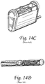
- FIG. 14 C is a perspective view of a platform assembly and movable member known in the art.
- FIG. 15 is a schematic block diagram of a preferred embodiment of the data processing system of the invention.
- FIG. 18 A is a graphical user interface displayed on the display device of the system of FIG. 15 that provides for operator input in marking a spatial attribute of the base of the prostate.
- FIG. 18 E is a graphical user interface displayed on the display device of the system of FIG. 15 that provides for operator input in selecting a particular biopsy pattern.
- FIG. 18 F is a graphical user interface displayed on the display device of FIG. 15 that provides for operator visualization of the locations of needle paths of a given biopsy plan carried out by the system of FIG. 15 .
- FIG. 18 G is a graphical user interface displayed on the display device of FIG. 15 that provides for operator-assisted detection of patient movement during the procurement of biopsy samples of a given biopsy plan.
- FIG. 19 A is a graphical user interface for repositioning of the probe and needle guide assembly (or an operator-inputted spatial attribute of a feature of the prostate) in order to correct for longitudinal movement of the patient relative to the probe.
- FIG. 19 B is a graphical user interface for repositioning the rotational position of the probe and the needle guide assembly (or an operator-inputted spatial attribute of a feature of the prostate) in order to correct for rotational movement of the patient relative to the probe.
- an improved transrectal ultrasonic probe 10 is shown in conjunction with a biopsy needle 110 , a cannula 112 for receiving and supporting the biopsy needle 110 , and a delivery system which includes a guide assembly 111 for guiding the biopsy needle 110 .
- the needle 110 and cannula 112 are preferably at least partially disposed within and coupled to a biopsy gun 107 .
- the biopsy needle 110 , cannula 112 , guide assembly 111 , and biopsy gun 107 are further discussed below with respect to the operation of these devices in conjunction with the improved probe 10 to capture biopsy tissue samples in a patient.
- the probe 10 has a housing 11 which includes a first elongate portion 12 , a second elongate portion 14 proximal of the first elongate portion, and a third elongate portion 16 proximal of the second elongate portion 14 .
- the first elongate portion 12 is substantially narrower (e.g., has a substantially smaller cross sectional area) than the second elongate portion 14 , and preferably has a circular cross section with an outside diameter of approximately 0.745 inches, preferably between 0.740 inches and 0.750 inches.
- the second elongate portion 14 preferably has a circular cross section with an outside diameter of approximately 1.06 inches, preferably between 0.75 inches and 1.4 inches.
- the third elongate portion 16 preferably has an outer body width of approximately 1.62 inches, preferably between 1.4 inches and 2.0 inches.
- the probe 10 also includes a distal end 13 which is preferably spherically shaped with a decreasing cross sectional area in the distal direction to assist with insertion of the probe 10 into a patient.
- the first elongate portion 12 is inserted into the rectum of the patient with the larger second elongate portion 14 remaining outside of the rectum of the patient.
- the first elongate portion 12 of the housing 11 houses an ultrasonic transducer 18 which is capable of emitting acoustic energy through the first elongate portion 12 and surrounding body cavity and tissue, and detecting acoustic backscatter signals.
- the transducer 18 is preferably mounted on a sled 20 which is rigidly coupled to a first connector 22 and slidably coupled to a guide portion 32 of a second connector 24 via a slot 26 defined by the bottom portion of the sled 20 .
- the transducer 18 is longitudinally translatable through the first elongate portion 12 , preferably parallel to a central axis 30 extending through the first elongate portion 12 .
- the first connector 22 translates longitudinally through the first elongate portion 12 , and functions to push and pull the transducer 18 distally and proximally along the guide portion 32 of the second connector 24 .
- a coiled coax 21 which carries transducer signal data is preferably wrapped around the first connector 22 as shown.
- the second connector 24 includes both the guide portion 32 and a support brace 34 .
- the guide portion 32 is preferably made from metal or steel and is rigidly attached to the distal end 13 of the probe 10 .
- the guide portion 32 preferably extends parallel to the central axis 30 .
- the support brace 34 defines a slot 36 ( FIGS. 5 , 6 ) for receiving a proximal section of the guide portion 32 and functions to support the guide portion 32 .
- the support brace 34 is made of a plastic material that allows it to deflect to prevent binding thereof when the first elongate portion 12 of the probe 10 is bent.
- the second connector 24 thus provides a guided pathway for directing longitudinal translation of the sled 20 as well as the transducer 18 .
- the second connector 24 minimizes unwanted movement of the sled 20 and transducer 18 .
- the second connector 24 rigidly maintains the radial position of the sled 20 and transducer 18 relative to the first elongate portion 12 of the housing 11 and provides support to the sled 20 and transducer 18 .
- the first and second connectors 22 , 24 extend between the first and second elongate portions 12 , 14 of the housing 11 , and respectively attach to a movable member and a platform assembly within the second elongate portion 14 as further discussed below with respect to FIGS. 4 and 6 .
- the second elongate portion 14 of the housing 11 houses a platform assembly 42 which is rotatable within and relative to the second elongate portion 14 and longitudinally fixed relative thereto.
- the platform assembly 42 supports a movable member 44 which translates relative to a frame 48 of the platform assembly 42 .
- the movable member 44 is both rotatable within and relative to the second elongate portion 14 , and translatable therethrough.
- the platform assembly 42 in addition to the frame 48 , includes a transmission system 46 .
- the transmission system 46 functions to drive reciprocating proximal and distal translation of the movable member 44 through the second elongate portion 14 , and preferably converts rotation of a proximally situated drive shaft (further discussed below) into the translation of the movable member.
- the transmission system 46 includes a vertical bevel gear 50 , a horizontal bevel gear 52 , a belt pulley 54 , a belt 56 , and an integral belt pin (not shown).
- the horizontal bevel gear 52 engages with the vertical bevel gear 50
- the belt 56 and belt pulley 54 rotate with the horizontal bevel gear 52 .
- the integral belt pin is fixed to the belt 56 , and is positioned in and slidable through a slot (not shown) on a bottom side of the movable member 44 . As the belt pulley 54 rotates, the pin moves with the belt 56 and pulls the movable member 44 along with it.
- the pin When the pin reaches and traverses one of the proximal (hidden) and distal 55 arced ends of the belt pulley 54 , it slides through the slot in the bottom of the movable member 44 and then pulls the movable member 44 in the opposite direction as it circles back with the belt 56 toward the other of the proximal and distal 55 arced ends of the belt pulley 54 .
- the frame 48 of the transmission system 46 (best seen in FIG. 6 A ) includes at least one track 58 which supports the movable member 44 and preferably extends parallel to a linear axis 60 through the second elongate portion 14 .
- the at least one track 58 may include, for example, two parallel beams or rails 59 .
- the movable member 44 is preferably a sled which is slidably coupled to the track 58 of the frame 48 as shown.
- the frame 48 includes a neck 61 that interfaces to a bearing 62 .
- the bearing 62 includes an outer race which is longitudinally and rotatably fixed relative to the second elongate portion 14 of the housing 11 , and an inner race 67 which is rotatable relative to the outer race and second elongate portion 14 .
- the neck 61 includes a plate portion 53 which is preferably situated in an interference fit with the inner race 67 of the bearing 62 .
- the plate portion 53 defines a first hole 64 for slidably receiving the first connector 22 , and a second hole 66 for rigidly receiving the second connector 24 .
- the bearing 62 functions to provide support to the frame 48 and first and second connectors 22 , 24 , and to prevent radial movement thereof relative to the housing 11 .
- the plate portion 53 includes additional holes 63 , 65 for allowing the ultrasonic fluid to freely flow between the first and second elongate portions 12 , 14 .
- the proximal end of the second elongate portion 14 is sealed so that no fluid flows into the third elongate portion 16 .
- the first connector 22 extends through the hole 64 , preferably parallel to the linear axis 60 between the parallel rails 58 of the frame 48 , and is rigidly coupled the movable member 44 at a proximal end 45 .
- the second connector 24 extends through the hole 66 , preferably parallel to the linear axis 60 , and is rigidly coupled to the neck 61 of the frame 48 .
- first connector 22 rigidly couples the transducer 18 in the first elongate portion 12 of the housing 11 to the movable member 44 in the second elongate portion 14 of the housing 11 , and thus that reciprocating proximal and distal longitudinal translation of the movable member 44 along the characteristic length L caused by the transmission system 46 causes reciprocating proximal and distal longitudinal translation of the transducer 18 within the first elongate portion 12 of the housing 11 along a length equivalent to the length L.
- the first connector 22 thus has a length which preferably exceeds the characteristic length L, and also which preferably exceeds the longitudinal length of the second elongate portion 14 such that when the movable member 44 is disposed in the proximal-most position in the frame 48 (e.g., FIGS. 4 & 6 B ), the first connector 22 still extends through the entire second elongate portion 14 and into the first elongate portion.
- the second connector 24 also preferably has a length which exceeds the characteristic length L as well as the longitudinal length of the second elongate portion. The second connector 24 slidably couples the transducer 18 to the platform assembly 42 .
- rotation of the entire platform assembly 42 about the central axis thereof 60 in either a clockwise or counterclockwise direction relative to the second elongate portion 14 of the housing 11 drives rotation of the movable member 44 and first and second elongate members 22 , 24 , which causes the transducer 18 to rotate in the same direction within the first elongate portion 12 about the central axis 60 .
- first and second elongate portions 12 , 14 of the housing 11 are fluidly coupled with each other and filled with an ultrasonic coupling medium (e.g., ultrasonic transmission oil) which flows freely between the first and second elongate portions 12 , 14 .
- an ultrasonic coupling medium e.g., ultrasonic transmission oil
- the third elongate portion 16 of the housing 11 can function as a handle for manual operation of the probe 10 , or can be grasped by a stand for automated operation thereof.
- the third elongate portion 16 houses a motor, clutch, brake, and control circuitry for driving the rotation of two coaxial drive shafts coupled to the frame 48 and the transmission system 46 of the platform assembly 42 in order to selectively rotate and translate the transducer 18 as further discussed below.
- the third elongate portion 16 preferably houses a single motor 68 which rotatably drives an inner drive shaft 70 .
- the inner drive shaft 70 extends from the motor 68 through the third elongate portion 16 of the housing 11 to the proximal end of the second elongate portion 14 where it is rotatably coupled to the vertical bevel gear 50 of the transmission system 46 ( FIGS. 6 A, 6 B ).
- the inner shaft 70 thus linearly and reciprocally drives the movable member 44 .
- An electrically controlled clutch 72 is mounted about the inner shaft 70 within the third elongate portion 16 , and an outer shaft 74 extends from the clutch 72 .
- the outer shaft 74 is hollow and surrounds the inner shaft 70 , which extends through it.
- the outer shaft 74 extends from the clutch 72 through the third elongate portion 16 of the housing 11 to the proximal end of the second elongate portion 14 where it is rotatably fixed to the frame 48 of the platform assembly 42 .
- An electrically controlled brake 76 is mounted about the outer shaft 74 within the third elongate portion 16 forward of the clutch 72 , and is operable to prevent rotation of the outer shaft 74 .
- the clutch 72 and brake 76 operate under control of electrical signals supplied by a motor control processor unit (MCPU).
- the MCPU can issue a signal which engages or disengages the clutch 72 and brake 76 .
- the clutch 72 When the clutch 72 is engaged, it locks (rotatably fixes) the inner and outer shafts 70 , 74 to each other such that the outer shaft 74 is rotated by the rotation of the inner shaft 70 .
- the outer shaft 74 is rotatably fixed to the frame 48 of the platform assembly 42
- rotation of the inner shaft 70 by the motor 68 drives rotation of the outer shaft 74 and the entire platform assembly 42 about its central axis 30 without operating the transmission system 46 .
- the clutch 72 When the clutch 72 is unengaged and the brake is engaged, rotation of the inner shaft 70 by the motor 68 operates the transmission system 46 as the inner shaft 70 rotates relative to the outer shaft 74 .
- the probe 10 preferably includes an outer shaft encoder (not shown) and an inner shaft encoder 71 for monitoring the longitudinal and rotational position of the transducer 18 .
- the encoders each include a wheel which rotates with a respective shaft, and a sensor which monitors the rotational position of the wheel as known in the art.
- the encoders send signals to the MCPU 73 indicative of the longitudinally and rotational position of the transducer 18 . Such rotational and positional feedback allows for accurate positioning and rotation of the transducer 18 within the probe 10 .
- the clutch 72 and brake 76 are controlled by a motion control processing unit (MCPU) 73 .
- the MCPU 73 is operatively connected to a control box or PC.
- the MCPU 73 engages and disengages the clutch 72 and brake 76 to allow for rotational and reciprocal motion of the transducer 18 in the first elongate portion 12 .
- the clutch 72 is released and the brake 76 is applied.
- the clutch 72 is engaged and the brake 76 is released.
- the MCPU 73 will signal the clutch 72 and brake 76 to engage or disengage depending on the commands initiated by the physician.
- the circuitry and electronics of the probe 10 preferably include a controller 83 , a pulser/receiver 85 , a digitizer 87 , and a high speed data interface 89 .
- the controller 83 receives commands from an external data processing system (e.g., a PC computer) 91 having a touch screen display 93 or other control dials and buttons via the data interface 89 . These commands are used to configure both the pulser/receiver 85 and the probe 10 .
- An acoustic pulse is generated in the pulser/receiver 85 and sent to the scanning probe 10 over a coaxial cable.
- Backscattered ultrasound data from the probe transducer 18 is processed by the receiver 85 .
- the data is then digitized by the digitizer 87 and sent to a memory buffer in the controller 83 .
- the data is then sent to the PC 91 for image formation on the touch screen display 93 via the data interface 89 .
- the controller 83 engages the clutch 72 and disengages the brake 76 to a low for rotational motion of the transducer 18 in the first elongate portion 12 while the transducer 18 remains longitudinally fixed relative thereto (the transmission system 46 is inoperable because the inner shaft 70 is rotatably fixed to the outer shaft 74 ).
- the controller 83 disengages the clutch 72 and engages the brake 76 to allow for reciprocating translation of the transducer 18 in the first elongate portion 12 while precluding rotation of it relative thereto (the inner shaft 70 is disengaged from the outer shaft 74 and drives the transmission system 46 , and the outer shaft 74 is prevented from rotating, which prevents rotation of the platform assembly 42 which is rotatably fixed to the outer shaft 74 , and hence the transducer 18 , which is rotatably fixed to the platform assembly 42 ).
- the controller 83 receives information on the position of the transducer 18 from a position tracker (not shown), which is connected to the probes rotational axis encoder 80 and linear axis encoder 78 .
- a position tracker not shown
- Various embodiments of the electronics driving operation of the probe 10 can be utilized, including all of those disclosed in U.S. patent application Ser. No. 11/475,674 which has been incorporated herein by reference.
- the improved probe 10 allows for controlled translational and rotational movement of the ultrasonic transducer 18 inside and across the substantially narrow distal scanning first elongate portion 12 of the probe's housing 11 .
- the narrow distal scanning first elongate portion 12 facilitates positioning and orienting of the probe 10 at different angles within the patient about the prostate, and imaging and biopsying the prostate as discussed below.
- a single connector may be utilized which rigidly couples the transducer 18 to the movable member 44 , provided that such single connector is sufficiently rigid to firmly maintain the radial position of the transducer 18 relative to the first elongate portion 12 of the housing 11 (e.g., provided the single connector does not bend). It is noted that a single connector should not be directly fixed to the frame 48 of the platform assembly 42 as it would need to translate with the movable member 44 relative to the frame 48 .
- the first connector 22 is sufficient to provide the aforementioned controlled movement to the transducer 18 without guide 32 and support 34 of the second connector 24 provided that the first connector 22 is fixed at both ends to the transducer 18 and movable member 44 , does not bend, and will not bend over repeated use of the probe 10 .
- the improved transrectal ultrasonic probe 10 may be used in conjunction with various biopsy needles and delivery systems known in the art, including, for example, those disclosed in U.S. patent application Ser. Nos. 11/895,228 and 11/475,674, which are herein incorporated by reference in their entireties, as well as the improved biopsy needle and delivery system of U.S. patent application Ser. No. 12/834,384, which is herein incorporated by reference in its entirety.
- the needle 110 includes a proximal end, a tissue piercing distal end 116 , a sampling section 118 proximal of the tissue piercing distal end 116 and having a flat top surface 124 , rounded bottom surface 126 , and ground down rounded edges 128 , 130 on opposite sides of the top surface 124 , a bending section 120 proximal of the sampling section 118 and preferably having a circular cross section, and a body portion 122 proximal of the bending section 120 .
- the sampling section 118 , bending section 120 , and body portion 122 of the needle 110 are all preferably solidly and integrally formed with varying degrees of flexibility.
- the bending section 120 is preferably the most flexible portion of the needle 110 .
- the improved probe 10 may be used in conjunction with the needle 110 , cannula 112 , and guide assembly 111 in accordance with the biopsy procedure described in U.S. patent application Ser. No. 12/834,357.
- various other methodologies, embodiments, and additional equipment may be utilized with the improved probe 10 to procure a biopsy sample, including, for example, the methodologies, embodiments, and additional equipment described in U.S. patent application Ser. No. 11/895,228.
- the improved ultrasonic probe 10 and needle assembly (e.g., needle 110 and cannula 112 ) are used with a delivery system which includes the guide assembly 111 and the biopsy gun 107 to procure a tissue sample from the prostate 184 of a patient.
- the needle 110 and cannula 112 preferably at least partially disposed within and coupled to the biopsy gun 107 .
- the narrow elongate distal scanning first elongate portion 12 of the improved probe 10 is inserted into the rectum of the patient adjacent the prostate 184 as shown n FIG. 13 .
- the substantially small scanning first elongate portion 12 of the housing 11 facilitates insertion into the rectum, and positioning and orienting the probe 10 therein.
- the probe 10 is preferably held by a cradle in a fixed stationary position.
- Transrectal probes commonly used in the art can cause significant discomfort to the patient, and the inventors have found that the transrectal probe of U.S. application Ser. Nos. 11/895,228 and 11/475,674 also can cause discomfort to patients.
- the substantially narrow distal scanning first elongate portion 12 of the new improved probe 10 reduces this discomfort.
- the guide assembly 111 is preferably attached to a guide/index collar 189 ( FIG. 1 ) of the probe 10 .
- the guide/index collar 189 controls radial and axial movement of the guide assembly 111 on the probe 10 , and preferably orients the guide assembly 111 such that it straddles the probe 10 adjacent an imaging window 123 in the probe 10 , and is sloped slightly downward at a ten degree angle.
- the guide assembly 111 may be fixed to the probe 10 and/or oriented horizontally relative thereto. Ultrasonic images of the prostate 184 are received through the imaging window 123 , unobstructed by the guide assembly 111 .
- the respective distal ends 116 , 156 of the needle 110 and cannula 112 are advanced together through the inlet of the guide assembly 111 and are guided to a fixed orientation and direction at the outlet 181 ( FIG. 12 B ) of the guide assembly 111 to place the needle 110 and cannula 112 in a bent configuration within the patient adjacent the prostate 184 .
- the biopsy gun 107 is fired to advance the needle 110 from the bent configuration into the prostate 184 of the patient.
- the sampling portion 118 of the needle 110 rapidly advances out of the cannula 112 into the prostate over a stroke length which is preferably approximately equal to the length of the sampling section 118 .
- a second firing of the biopsy gun 107 causes the cannula 112 to fire and advance over the exposed sampling section 118 of the needle 110 in the prostate 184 , capturing sample tissue therein between the cannula 112 and the needle 110 .
- the needle 110 and cannula 112 are then withdrawn from the patient with the tissue sample captured within the cannula 12 , and the process is repeated as needed with the improved probe 10 remaining in the patient. It will be appreciated that the narrower distal elongate portion 12 of the housing 11 of the new probe 10 allows for easier manipulation inside of the patient to different positions and orientations.
- an exemplary data processing apparatus such as the data processing system 200 , includes a memory controller and graphics interface 210 that interface between a memory system 230 and one or more CPU(s) 220 .
- Interface 210 also interfaces to a display adapter 240 that generates and outputs display windows for display on a display device 260 connected thereto.
- An input/output controller 250 provides an interface (USB interface) to an imaging device, such as the probe 10 , and to an input device, such as a touch screen input device 280 that overlays the display screen of the display device 260 .
- the touch screen input device 280 can be a separate unit that is attached and secured to the display device 260 (or can be integrally formed as part of the display device 260 ).
- the input/output controller 250 also provides an interface (e.g. SATA) to a data storage medium, such as a hard disk 265 , for data storage.
- a data storage medium such as a hard disk 265
- the hard disk 265 stores software logic loaded into the memory system 230 for execution by the CPU(s) 220 .
- the software logic preferably maintains an linage buffer for storing two dimensional image data derived from sagittal and transverse scan planes of the target tissue (e.g., prostate).
- the display device 260 of the data processing system 200 displays biopsy information and various on-screen controls for touch input by an operator via the touch-screen input device 280 as further discussed below.
- the data processing system 200 interacts with the operator to identify spatial attributes of various features of the prostate (referred to herein as operator-assisted feature localization), scan the prostate, define a biopsy plan, and procure biopsy samples of the prostate in accordance with the biopsy plan while monitoring and adjusting for patient movement.
- operator-assisted feature localization referred to herein as operator-assisted feature localization
- the probe 10 is positioned in the patient's rectum while the system 200 displays live sagittal and transverse images of the prostate 184 .
- Sagittal images are displayed in a sagittal display window 268 ( FIGS. 17 and 18 A ) of the display device 260 and transverse images are displayed in a transverse display window 269 .
- a visual representation of the live imaging plane is superimposed on a three-dimensional graphical representation of a typical prostate gland in a viewport display window 270 ( FIGS. 17 and 18 A ) of the display device 260 as taught in U.S. Patent Appl. Publ. No. 2008/0146933, commonly assigned to assignee of the present invention and herein incorporated by reference in its entirety.
- the operator can control the imaging probe 10 and display to move to another live sagittal image plane or another live transverse image plane by touch input or other suitable user input controls.
- the operator can move to a live sagittal image plane by touching the transverse display window 269 at a user-selected point.
- the imaging probe 10 automatically scans the sagittal image plane that passes through the user-selected point dictated by the touch input, the sagittal display window 268 is updated to display the image data of the scanned sagittal imaging plane as captured by the probe, and the viewport display window 270 is updated to show a visual representation of the new live sagittal plane superimposed on the three-dimensional graphical representation of a typical prostate gland.
- the operator can move to a live transverse image plane by touching the sagittal display window 268 at a user-selected point.
- the imaging probe 10 automatically scans the transverse image plane that passes through the user-selected point dictated by the touch input, the transverse display window 269 is updated to display the image data of the scanned transverse imaging plane as captured by the probe, and the viewport display window is updated to show a visual representation of the new live transverse imaging plane superimposed on the three-dimensional graphical representation of a typical prostate gland.
- the operator utilizes the live sagittal and transverse images of the prostate to center the probe 10 .
- the operator adjusts the probe 10 until the live images of the prostate show the prostate 184 centered in a center sagittal image plane displayed in the sagittal display window 268 , and possibly also centered in one or more live transverse images displayed in the transverse display window 269 .
- center sagittal image plane is used herein to refer to the sagittal image plane which passes through the approximate center of the prostate 184 and thus divides the prostate into two halves.
- the probe 10 is preferably held by a cradle in a fixed stationary position.
- the operator touches a button on the display device 260 .
- the system 200 then scans, captures, stores, and displays an image of the center sagittal image plane in the sagittal display window 268 and interacts with the operator to identify various spatial attributes of one or more operator-identified features of the prostate which appear in the sagittal image displayed in the display window 268 .
- the system 200 interacts with the operator to identify a spatial attribute of the base 362 of the prostate by displaying a vertical line 364 (labeled “B” in FIG. 18 A ) overlaid upon the sagittal image of the center sagittal image plane in the sagittal display window 268 .
- the operator can adjust the horizontal position of the vertical line 364 by touch input (or by manipulation of fine adjustment buttons (not shown) or other suitable user input controls) such that it intersects the base 362 of the prostate as displayed in the sagittal display window 268 .
- the system 200 identifies and stores the ‘x’ pixel coordinate of the operator-positioned vertical line 364 after it has been located at the base 362 . In this manner, the ‘x’ pixel coordinate of the operator-positioned vertical line 364 represents data corresponding to the operator-inputted spatial attribute of the base of the prostate.
- Similar operations can be performed to identify a spatial attribute of the apex 366 of the prostate by displaying a vertical line 368 (labeled “A” in FIG. 18 B ) overlaid upon the sagittal image of the center sagittal image plane in the sagittal display window 268 .
- the operator can adjust the horizontal position of the vertical line 368 by touch input (or by manipulation of fine adjustment buttons (not shown) or other suitable user input controls) such that it intersects the apex 366 of the prostate as displayed in the sagittal display window 268 .
- the system 200 identities and stores the ‘x’ pixel coordinate of the operator-positioned vertical line 368 after it has been located at the apex 366 . In this manner, the ‘x’ pixel coordinate of the operator-positioned vertical line 368 represents data corresponding to the operator-inputted spatial attribute of the apex of the prostate.
- the vertical line used to define the spatial attribute of a given feature of the prostate can be substituted with (or complimented by) other suitable visual position indicators, such as an ‘X’, a bull's eye, or other visual mark or icon overlaid on the display window 268 .
- suitable visual position indicators such as an ‘X’, a bull's eye, or other visual mark or icon overlaid on the display window 268 .
- the operator may interact with the system 200 by touch input or alternatively by use of a mouse, tracking ball, keyboard entries, etc., to properly position the vertical line, on-screen cursor, or other indicator.
- the system 200 can also interact with the operator to input spatial attributes representing the length of the prostate (which extends from the bladder neck to the apex of the prostate), and to derive data representing the length of the prostate from the operator-inputted spatial attributes.
- the system 200 also preferably interacts with the operator to input the spatial attributes of the anterior and posterior edges of the prostate in the sagittal display window 268 , to store data corresponding to these marked spatial attributes, and to calculate the height of the prostate from this stored data.
- the system 200 scans, captures, stores, and displays a single transverse image of the center transverse image plane in the transverse display window 269 and interacts with the operator to identify various spatial attributes of one or more operator-identified features of the prostate which appear in the transverse image displayed in the transverse display window 269 .
- the system 200 may interact with the operator to select the “widest” transverse imaging plane where the cross sectional profile of the prostate is the widest. The operator may toggle through various live transverse images of different transverse planes through the prostate and select the widest one.
- the system 200 then interacts with the operator to mark the prostate's leftmost and rightmost peripheral projections in this “widest” transverse imaging plane displayed in the transverse display window 269 using a vertical line, an indicator, etc. as discussed above.
- the system 200 stores data corresponding to the operator inputted and marked spatial attributes of the prostate's leftmost and rightmost peripheral projections in the “widest” transverse imaging plane of the prostate and calculates the width of the prostate from the stored data.
- the system 200 can interact with the operator to input angular scanning limits of the probe 10 (e.g., the right and left angles relative to the centerline of the probe which represent the angular limits through which the probe 10 must scan in order to scan the prostate in its entirety).
- the operator can designate the right scanning angle by displaying a line 370 overlaid upon the transverse image of the transverse image plane displayed in the transverse display window 269 as shown in FIG. 18 C .
- the operator can adjust the rotational orientation of the line 370 by touch input (or by manipulation of fine adjustment buttons (not shown) or other suitable user input controls) such that it intersects the right angular boundary of the prostate as displayed in the transverse display window 269 .
- the system 200 identifies and stores the rotational angle of the operator-positioned line 370 after it has been located at the right angular boundary of the prostate. Similar operations can be performed for the left scanning angle. In this manner, the rotational angles of the operator-positioned lines represents data corresponding to the angular limits through which the probe 10 must scan in order to scan the prostate in its entirety. It will be appreciated that transverse image data in multiple transverse planes (in additional to the ‘widest’ transverse plane) may need to be viewed in the transverse display window 269 in order to ensure that the true angular limits of the prostate have been captured.
- the system 200 may also interact with the operator to input a contour around the prostate in various transverse images 269 A, 269 B, 269 C of the prostate displayed on the display device 260 as shown in FIG. 18 D .
- Such contours may be drawn around the outer border of prostate appearing in the images by touch input of the operator, or by other input as discussed above.
- the system 200 stores these spatial attributes of the prostate as well.
- the system 200 can derive the length, width, and height of the prostate as discussed above with respect to blocks 303 and 305 by maintaining various coordinate systems (e.g., a display coordinate system, probe coordinate system (see Xc, Yc, Zc of FIG. 2 ), guide assembly coordinate system, etc.) as well as transformations therebetween.
- the system 200 can calculate the length of the prostate in the probe coordinate system of FIG. 2 by transforming the ‘x’ pixel coordinate values of the operator adjusted vertical lines depicting the relative locations of the bladder neck and apex to corresponding positions in the probe coordinate system utilizing a transformation between the display coordinate system of the display device 260 and the probe coordinate system, and then subtracting the resultant coordinates.
- data corresponding to operator-inputted spatial attribute(s) of a feature can be defined and stored in one or more of these coordinate systems.
- the system 200 can calculate the volume of the prostate, preferably using these values in conjunction with a suitable empirical model.
- the features marked by the operator at blocks 303 and 305 are preferably common, easily identifiable features and discriminative of prostate position over a wide range of patients. It is also contemplated that in addition to the modes of operator input described above, the operator may provide touch input to the data processing system 200 via a virtual keypad displayed on one of the display windows 268 , 269 of the touch-screen display 260 . Other suitable user interface mechanisms can also be utilized.
- the operator-inputted spatial attributes of each feature are stored by the software and memory controller 210 , preferably on the hard disk 265 or in other suitable data storage medium.
- the system 200 defines a set of image planes that are distributed over the three-dimensional volume of the prostate as dictated by the spatial attributes of the operator-identified features of the prostate at blocks 303 and 305 .
- the scan planes can include sagittal scan planes sampled at a regular angular spacing and/or transverse scan planes sampled at a regular depth spacing.
- the three dimensional scan volume of the prostate resembles a truncated cylinder which is bounded by oppositely facing transverse planes (passing through the bladder neck and apex of the prostate) and by sagittal planes passing through the left and right angular limits inputted by the operator at block 305 .
- the system 200 conducts a full three dimensional scan of the prostate using the scan planes defined in block 307 .
- the full three-dimensional scan uses a series of sagittal scan planes sampled at a regular angular spacing and/or transverse scan planes sampled at regular depth spacing. If only one of such two sets of data is taken or available, then one may be interpolated from the other.
- the software logic maintains an image buffer for storing the two dimensional image data derived from the sagittal and/or transverse scan planes of the prostate.
- the data processing system 200 derives a plurality of biopsy patterns 372 ( FIG. 18 E ).
- the patterns vary in terms of the total number of samples (e.g., between twelve and thirty-two as shown in FIG. 18 E ) and the distribution of the samples through the prostate.
- the biopsy patterns 372 can target areas of the prostate where cancer is most likely to be found and are preferably based on accepted biopsy practice.
- the system 200 interacts with the operator to select one of the biopsy patterns. For example, as shown in FIG. 18 E , the system 200 can display the plurality of biopsy patterns 372 at the lower left portion of the display 260 and provide operator controls for selecting one of them.
- the system 200 automatically derives a biopsy plan corresponding to the selected biopsy pattern.
- the biopsy plan includes needle paths (i.e., a direction and distance) through which the needle assemblies will be advanced to procure the desired biopsy samples of the prostate, as well as longitudinal and rotational coordinates for positioning the needle guide assembly such that it directs the needle assembly along the respective needle paths as further discussed below.
- the needle paths are preferably derived by the data processing system 200 according to the operator-selected biopsy pattern.
- the system 200 derives the needle paths of the biopsy plan based on the size of the prostate and the particular biopsy pattern selected in block 311 (e.g., number of samples and desired distribution of the samples).
- the system 200 is also optionally configurable to allow the operator to create, add and/or remove needle paths to/from the biopsy plan. These decisions may be based on knowledge gleaned from prior scans and procedures and/or from current images of the prostate.
- the operator interacts with the system 200 to visualize and review the needle paths of the biopsy plan defined in block 313 , and provide an indication that the needle path is complete or finalized.
- the system 200 is configured with user input controls such that the operator can sequence through the samples/needle paths of the plan to visualize the location of the samples/needle paths of the plan and make adjustments to the needle paths of the plan and/or delete or add needle paths to the plan as desired.
- FIG. 18 F shows touch input control 380 a that enables the operator to sequence through the needle paths/samples of the plan and touch input control 380 b that enables the operator to add or delete needle paths/samples from the plan.
- Touch input controls 382 a , 382 b allow the operator to adjust the angle of the current needle path
- touch input controls 384 a , 384 b allow the operator to adjust the depth of the current needle path.
- the viewport display window 270 may also be adapted to display lines representing the needle paths of the plan superimposed on the 3D representation of the typical prostate as shown in FIG. 18 F .
- each respective needle path onto the sagittal image plane displayed in the sagittal display window 268 can be shown as a line 374 a superimposed on the sagittal image displayed in the sagittal display window 268 and/or a circle 374 b (or other suitable indicia) that indicates the location where the respective needle path intersects the sagittal image plane displayed in the sagittal display window 268 as shown in FIG. 18 F .
- each respective needle path corresponds to a vector in the probe coordinate system ( FIG. 2 ).
- line 374 a is displayed for the respective needle path by projecting the needle path vector onto the sagittal image plan and displaying the resultant projected line.
- the operator can select a given needle path of the plan and the display device 260 may indicate the selected needle path by, for example, changing the color of the appropriate line and circle for the selected needle path.
- the operator may add a specific needle path to the biopsy plan, such as by selecting an on-screen button. Each time a needle path is selected, the displays windows 268 , 269 and 270 are updated accordingly. The operator may also remove a specific needle path from the biopsy plan as described above. Once the operator has finished adding or removing needle paths from the selected biopsy plan, the operator indicates that the plan is complete and the plan data is persistently stored on the hard disk 265 .
- the data processing system 200 interacts with the operator at block 317 to begin procuring biopsy samples in accordance with the biopsy plan finalized in block 315 .
- the system 200 may also be adapted to allow the operator to modify the biopsy plan at any time in the process, either by adding or canceling needle paths.
- the operations perform a loop (blocks 317 to block 333 ) over the number of samples in the biopsy plan.
- the system 200 controls the probe 10 to rescan at least one of the predetermined image planes (e.g., the center sagittal image plane and/or the transverse image plane where the prostate is the “widest”) previously scanned and “marked” by the operator as part of the operator-assisted feature localization process of blocks 303 and/or 305 .
- the predetermined image planes e.g., the center sagittal image plane and/or the transverse image plane where the prostate is the “widest
- the system 200 displays the refreshed (new) image data of the predetermined image plane(s) as captured by the rescanning of the probe 10 in a predefined display window of the display device 260 , and superimposes a graphical representation (e.g., a vertical line, an icon, or other display element) of one or more of the operator-inputted spatial attributes of a feature (inputted at blocks 303 , 305 , or during realignment of the probe 10 as further discussed below) on the predefined display window at a corresponding display window location.
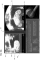
- FIG. 18 G shows a predefined display window 271 that displays the refreshed image data of the center sagittal image plane.
- a vertical line 273 is superimposed on the image displayed in the display window 271 at window coordinates corresponding to the operator-marked spatial attribute of the apex derived in block 303 as described above ( FIG. 18 B ).
- a vertical line 275 is superimposed on the image displayed in the display window 271 at window coordinates corresponding to the operator-marked spatial attribute of the base derived in block 303 as described above ( FIG. 18 A ).
- the operator visually compares the current spatial attributes of the operator-marked feature(s) to the previously inputted operator-marked spatial attributes(s) of the feature(s) in the predefined display window. For example, turning to FIG. 18 G , the position of the apex and base of the prostate 184 can be visually evaluated in the display window 271 by determining whether either one (or both) of the vertical lines 273 , 275 have shifted relative to the apex and base of the prostate appearing in the center sagittal image displayed in display window 271 . If so, then such misalignment indicates that the patient has moved longitudinally relative to the probe 10 (depth-wise) since the last scan of the predetermined image plane (e.g. the center sagittal plane).
- the predetermined image plane e.g. the center sagittal plane
- Suitable visualizations can be used to detect patient movement as part of block 323 .
- the operator can evaluate whether the patient has rotated relative to the probe 10 since the last scan of the center transverse plane by evaluating whether the contour of the prostate in a refreshed image of a predetermined transverse imaging plane (e.g., the center transverse image) aligns with the location of the prostate contour inputted by the operator either at block 305 (or possible input by the operator during realignment of the probe in block 325 ).
- a predetermined transverse imaging plane e.g., the center transverse image
- one method of realignment is to mechanically adjust the longitudinal and/or rotational position of the probe. If the patient has moved in the longitudinal direction of the probe (i.e., depthwise within the rectum), then the probe 10 may be moved in a longitudinal direction opposite the direction that the patient has moved. In order to aid the operator in realigning the probe, the probe can be controlled to scan the center sagittal scan plane, and the refreshed center sagittal image can be displayed in the sagittal display window 268 along with the previously inputted operator-marked spatial attributes(s) of the feature(s) of the prostate (e.g., vertical lines for the base and apex of the prostate) as shown in FIG. 19 A .
- the previously inputted operator-marked spatial attributes(s) of the feature(s) of the prostate e.g., vertical lines for the base and apex of the prostate
- Such scan/center sagittal image refresh operations can be triggered by operator control, for example, by touch screen input. These operations can be repeated until the operator sees alignment between the current spatial attribute(s) of the features in the refreshed image and the previously inputted spatial attributes.
- the operator can readjust the spatial attributes of the features on-screen, for example by user-input controls that shift the vertical lines for the base and apex of the prostate.
- the operator can adjust the rotational alignment of the probe 10 until the outer edges of the prostate in the transverse image fall within the contour 371 as shown in FIG. 19 B .
- the operator can readjust the spatial attributes of the features on-screen, for example by user-input controls that rotate the contour of the prostate.
- the operator positions the needle guide assembly 111 at longitudinal and rotational coordinates which correspond to the current needle path of the loop (blocks 317 - 333 ).
- the system 200 calculates the longitudinal and rotational coordinates of the needle guide assembly based on the particular geometry and position of the current needle path. As discussed above, the system 200 derives the needle paths from the specific biopsy pattern selected at block 311 and the spatial attributes entered by the operator at blocks 303 and 305 , and uses this data in conjunction with various reference coordinate systems and transformations therebetween to derive the longitudinal and rotational coordinates of the needle guide assembly 111 .
- the system 200 evaluates whether or not all of the samples of the biopsy plan have been procured. If so, then loop of blocks 317 to 333 ends. Otherwise, the operations return to block 317 to procure the next sample of the biopsy plan.
- system and methodology of the present invention allows for all of the biopsy samples of the biopsy plan to be taken from the prostate while visually monitoring real time spatial attributes of feature(s) of the prostate relative to previously inputted operator-marked spatial attribute(s) of the feature(s). In this manner, the operator can adjust for patient movement between samples and better adhere to the desired biopsy plan of sampling the prostate in specifically targeted areas.
- the system of the present invention can be used to detect patient movement during the delivery of treatment to localized areas (typically referred to as “target sites”) of the prostate.
- the guide assembly 111 of the system is rotatively and longitudinally positioned atop the probe such that it guides a flexible cannula (or other elongate flexible instrument) transrectally along a path leading to the respective target site.
- the distal tip of the flexible instrument is positioned at the respective target side for application of the localized treatment to the target site.
- the system and method of the present invention as described herein can be used to visually detect patient movement before treatment is applied to a respective target site.
- the treatment applied to the target site can take many forms, including but not limited to:
- Brachytherapy is a minimally invasive treatment that administers radioactive seeds (the size of a grain of rice) directly into the prostate, which allows the ability to use higher doses in the seeds without damaging any surrounding healthy tissue.
- the radioactive seeds are placed into thin needles and directed into the prostate through the perineum.
- the seeds release low dose radiation for several weeks or months, killing the cancer cells.
- Cryotherapy uses argon gas to freeze and helium gas to thaw, a process which destroys cancer cells in the prostate.
- a warming catheter is inserted through the urethra to protect it during the freezing process of the prostate. The cancer cells in the prostate are destroyed as they thaw.
- the improved ultrasonic probe may also be used to provide guidance during transperineal procedures, including brachytherapy, cryotherapy, or other transperineal saturation biopsies in which the needle is inserted through a grid through the perineum and transrectal images from the probe are used for guidance.
- the probe may also be used for guidance during laparoscopic and non-laparoscopic surgeries involving other cavities such as the abdominal cavity (e.g., surgeries involving the small intestine, large intestine, stomach, spleen, liver, pancreas, kidneys, and adrenal glands), the thoracic cavity, and the pelvic cavity, or during surgeries involving other tissue or joints in the body.
- the abdominal cavity e.g., surgeries involving the small intestine, large intestine, stomach, spleen, liver, pancreas, kidneys, and adrenal glands
- the thoracic cavity e.g., surgeries involving the small intestine, large intestine, stomach, spleen, liver, pancreas, kidneys, and adrenal glands
- the thoracic cavity e.g., thoracic cavity
- the pelvic cavity e.g., surgeries involving other tissue or joints in the body.
- the needle, cannula, and improved probe have been disclosed for biopsying the prostate of a patient, it will be recognized that the needle, cannula, and improved probe can be used for biopsying tissue of other organs or other parts of the body and that the improved probe may be inserted through other cavities in the body and utilized for guiding other procedures such as brachytherapy, cryotherapy and saturation biopsies. It will also be appreciated that while a method for procuring biopsy samples in the prostate and for detecting movement of the patient relative to a transrectal probe has been disclosed, the method may be used for other targeted tissue within or adjacent a body cavity of the patient.
Landscapes
- Health & Medical Sciences (AREA)
- Life Sciences & Earth Sciences (AREA)
- Engineering & Computer Science (AREA)
- Surgery (AREA)
- Medical Informatics (AREA)
- General Health & Medical Sciences (AREA)
- Public Health (AREA)
- Nuclear Medicine, Radiotherapy & Molecular Imaging (AREA)
- Biomedical Technology (AREA)
- Veterinary Medicine (AREA)
- Molecular Biology (AREA)
- Animal Behavior & Ethology (AREA)
- Heart & Thoracic Surgery (AREA)
- Pathology (AREA)
- Radiology & Medical Imaging (AREA)
- Physics & Mathematics (AREA)
- Biophysics (AREA)
- Computer Vision & Pattern Recognition (AREA)
- Oral & Maxillofacial Surgery (AREA)
- Theoretical Computer Science (AREA)
- General Physics & Mathematics (AREA)
- Physiology (AREA)
- Robotics (AREA)
- Human Computer Interaction (AREA)
- Gynecology & Obstetrics (AREA)
- Multimedia (AREA)
- Quality & Reliability (AREA)
- Primary Health Care (AREA)
- Epidemiology (AREA)
- Databases & Information Systems (AREA)
- Data Mining & Analysis (AREA)
- Ultra Sonic Daignosis Equipment (AREA)
Abstract
Description
-
- placement of gold or other forms of markers at the target site;
- placement of one or more cryotherapy probes at the target site;
- placement of one or more brachytherapy seeds at the target site;
- delivery of laser therapy (or other forms of radiation therapy) to the target site;
- delivery of drugs to the target site; and
- delivery of other forms of therapy including heat and vapors to the target site.
Claims (28)
Priority Applications (2)
| Application Number | Priority Date | Filing Date | Title |
|---|---|---|---|
| US12/970,060 US11612377B2 (en) | 2010-12-16 | 2010-12-16 | Image guided surgical methodology and system employing patient movement detection and correction |
| PCT/US2011/063226 WO2012082418A1 (en) | 2010-12-16 | 2011-12-05 | Image guided surgical methodology (and system) employing patient movement detection and correction |
Applications Claiming Priority (1)
| Application Number | Priority Date | Filing Date | Title |
|---|---|---|---|
| US12/970,060 US11612377B2 (en) | 2010-12-16 | 2010-12-16 | Image guided surgical methodology and system employing patient movement detection and correction |
Publications (2)
| Publication Number | Publication Date |
|---|---|
| US20120157841A1 US20120157841A1 (en) | 2012-06-21 |
| US11612377B2 true US11612377B2 (en) | 2023-03-28 |
Family
ID=46235283
Family Applications (1)
| Application Number | Title | Priority Date | Filing Date |
|---|---|---|---|
| US12/970,060 Active US11612377B2 (en) | 2010-12-16 | 2010-12-16 | Image guided surgical methodology and system employing patient movement detection and correction |
Country Status (2)
| Country | Link |
|---|---|
| US (1) | US11612377B2 (en) |
| WO (1) | WO2012082418A1 (en) |
Families Citing this family (33)
| Publication number | Priority date | Publication date | Assignee | Title |
|---|---|---|---|---|
| US8814921B2 (en) | 2008-03-06 | 2014-08-26 | Aquabeam Llc | Tissue ablation and cautery with optical energy carried in fluid stream |
| US9232959B2 (en) | 2007-01-02 | 2016-01-12 | Aquabeam, Llc | Multi fluid tissue resection methods and devices |
| US12290277B2 (en) | 2007-01-02 | 2025-05-06 | Aquabeam, Llc | Tissue resection with pressure sensing |
| US9848904B2 (en) | 2009-03-06 | 2017-12-26 | Procept Biorobotics Corporation | Tissue resection and treatment with shedding pulses |
| US10588609B2 (en) | 2010-02-04 | 2020-03-17 | Procept Biorobotics Corporation | Gene analysis and generation of stem cell methods and apparatus |
| WO2016004071A1 (en) | 2014-06-30 | 2016-01-07 | Procept Biorobotics Corporation | Fluid jet tissue resection and cold coagulation (aquablation) methods and apparatus |
| US20120095371A1 (en) * | 2010-10-18 | 2012-04-19 | CardioSonic Ltd. | Ultrasound transducer and cooling thereof |
| US11911117B2 (en) | 2011-06-27 | 2024-02-27 | Board Of Regents Of The University Of Nebraska | On-board tool tracking system and methods of computer assisted surgery |
| EP2723270B1 (en) | 2011-06-27 | 2019-01-23 | Board of Regents of the University of Nebraska | On-board tool tracking system of computer assisted surgery |
| US9498231B2 (en) | 2011-06-27 | 2016-11-22 | Board Of Regents Of The University Of Nebraska | On-board tool tracking system and methods of computer assisted surgery |
| CN108606773B (en) | 2012-02-29 | 2020-08-11 | 普罗赛普特生物机器人公司 | Automated image-guided tissue resection and processing |
| US9798856B2 (en) * | 2012-03-21 | 2017-10-24 | Koninklijke Philips N.V. | Clinical workstation integrating medical imaging and biopsy data and methods using same |
| WO2013155156A1 (en) * | 2012-04-10 | 2013-10-17 | The Johns Hopkins University | Cohesive robot-ultrasound probe for prostate biopsy |
| US10357304B2 (en) | 2012-04-18 | 2019-07-23 | CardioSonic Ltd. | Tissue treatment |
| EP2956070A4 (en) | 2013-02-14 | 2016-12-07 | Procept Biorobotics Corp | METHODS AND APPARATUS FOR AQUABEAM EYE SURGERY OF FLUID JET ABLATION |
| US10105149B2 (en) | 2013-03-15 | 2018-10-23 | Board Of Regents Of The University Of Nebraska | On-board tool tracking system and methods of computer assisted surgery |
| US10231701B2 (en) * | 2013-03-15 | 2019-03-19 | Provisio Medical, Inc. | Distance, diameter and area determining device |
| KR102136174B1 (en) * | 2013-08-13 | 2020-07-21 | 삼성메디슨 주식회사 | Ultrasonic diagnostic apparatus |
| CN105764436B (en) | 2013-09-06 | 2019-04-26 | 普罗赛普特生物机器人公司 | A device for ablating tissue using a deactivation pulse |
| US10743909B2 (en) * | 2014-04-03 | 2020-08-18 | Corbin Clinical Resources, Llc | Transperineal prostate biopsy device, systems, and methods of use |
| KR102288308B1 (en) | 2014-08-05 | 2021-08-10 | 삼성메디슨 주식회사 | Ultrasonic Diagnostic Apparatus |
| ES2842750T3 (en) | 2014-09-05 | 2021-07-14 | Procept Biorobotics Corp | Cell isolation apparatus |
| BR112017004431B1 (en) | 2014-09-05 | 2022-11-01 | Procept Biorobotics Corporation | APPLIANCE FOR TREATMENT OF A PATIENT |
| CN107920775A (en) * | 2015-06-25 | 2018-04-17 | 瑞文那医疗有限责任公司 | Guided relative to the probe sonication of anatomical features |
| EP3340919B1 (en) | 2015-08-27 | 2020-09-30 | Focal Healthcare Inc. | Moveable interface and stepper assembly |
| EP3510932A1 (en) * | 2018-01-11 | 2019-07-17 | Koninklijke Philips N.V. | Ultrasound device for in-situ ultrasound imaging |
| US11382601B2 (en) * | 2018-03-01 | 2022-07-12 | Fujifilm Sonosite, Inc. | Method and apparatus for annotating ultrasound examinations |
| JP6748139B2 (en) * | 2018-04-02 | 2020-08-26 | ファナック株式会社 | Visual guidance device, visual guidance system, and visual guidance method |
| WO2020142338A1 (en) * | 2018-12-31 | 2020-07-09 | Xact Medical, Inc. | Needle insertion into subcutaneous target |
| EP3943007B1 (en) | 2020-07-23 | 2025-03-19 | Siemens Healthineers AG | Method, device and system for providing a virtual medical procedure drill |
| WO2023027637A2 (en) * | 2021-08-23 | 2023-03-02 | Biobot Surgical Pte Ltd | Method and system for determining a trajectory of an elongated tool |
| CN114748165B (en) * | 2022-04-18 | 2023-07-14 | 山西医科大学 | Ultrasonic radar three-dimensional scanning device for resectoscope |
| US12539103B2 (en) * | 2024-07-04 | 2026-02-03 | GE Precision Healthcare LLC | System, method and/or computer readable medium for an improved instrument guidance approach in ultrasound imaging |
Citations (20)
| Publication number | Priority date | Publication date | Assignee | Title |
|---|---|---|---|---|
| US5592942A (en) | 1992-06-30 | 1997-01-14 | Cardiovascular Imaging Systems, Inc. | Automated longitudinal position translator for ultrasonic imaging probes, and methods of using same |
| US5954670A (en) | 1994-10-05 | 1999-09-21 | Baker; Gary H. | Mandrel-guided tandem multiple channel biopsy guide device and method of use |
| US6004271A (en) | 1998-05-07 | 1999-12-21 | Boston Scientific Corporation | Combined motor drive and automated longitudinal position translator for ultrasonic imaging system |
| US6200269B1 (en) | 1998-05-28 | 2001-03-13 | Diasonics, Ultrasound, Inc. | Forward-scanning ultrasound catheter probe |
| US20030112922A1 (en) * | 2001-11-05 | 2003-06-19 | Computerized Medical Systems, Inc. | Apparatus and method for registration, guidance and targeting of external beam radiation therapy |
| US20040034297A1 (en) * | 2002-08-13 | 2004-02-19 | General Electric Company | Medical device positioning system and method |
| US6709397B2 (en) | 2001-10-16 | 2004-03-23 | Envisioneering, L.L.C. | Scanning probe |
| US20050159676A1 (en) * | 2003-08-13 | 2005-07-21 | Taylor James D. | Targeted biopsy delivery system |
| US20070010805A1 (en) * | 2005-07-08 | 2007-01-11 | Fedewa Russell J | Method and apparatus for the treatment of tissue |
| US20070038112A1 (en) | 2001-10-16 | 2007-02-15 | Taylor James D | Scanning probe with integrated electronics |
| US20070043293A1 (en) * | 2003-02-20 | 2007-02-22 | Siemens Medical Solutions Usa, Inc. | Measuring transducer movement methods and systems for multi-dimensional ultrasound imaging |
| US20080146933A1 (en) | 2003-12-01 | 2008-06-19 | Stephen Lewis | Ultrasonic image and visualization aid |
| US20090182312A1 (en) | 2008-01-11 | 2009-07-16 | Oraya Therapeutics, Inc. | Device and assembly for positioning and stabilizing an eye |
| US20090318804A1 (en) | 2006-05-02 | 2009-12-24 | Galil Medical Ltd. | Cryotherapy Planning and Control System |
| US7835557B2 (en) | 2006-11-28 | 2010-11-16 | Medtronic Navigation, Inc. | System and method for detecting status of imaging device |
| US20110082363A1 (en) * | 2008-06-20 | 2011-04-07 | Koninklijke Philips Electronics N.V. | Method and system for performing biopsies |
| US20110081063A1 (en) * | 2007-09-18 | 2011-04-07 | Koelis | System and method for imaging and locating punctures under prostatic echography |
| US20120203095A1 (en) * | 2010-11-25 | 2012-08-09 | Hologic, Inc. | Systems and Methods for Trans-Orifice and Transperineal Intervention |
| US20130090554A1 (en) * | 2010-06-24 | 2013-04-11 | Uc-Care Ltd. | Focused prostate cancer treatment system and method |
| US8702579B2 (en) | 2009-08-31 | 2014-04-22 | Koelis | Control system and method for precisely guiding a percutaneous needle toward the prostate |
-
2010
- 2010-12-16 US US12/970,060 patent/US11612377B2/en active Active
-
2011
- 2011-12-05 WO PCT/US2011/063226 patent/WO2012082418A1/en not_active Ceased
Patent Citations (21)
| Publication number | Priority date | Publication date | Assignee | Title |
|---|---|---|---|---|
| US5592942A (en) | 1992-06-30 | 1997-01-14 | Cardiovascular Imaging Systems, Inc. | Automated longitudinal position translator for ultrasonic imaging probes, and methods of using same |
| US5954670A (en) | 1994-10-05 | 1999-09-21 | Baker; Gary H. | Mandrel-guided tandem multiple channel biopsy guide device and method of use |
| US6004271A (en) | 1998-05-07 | 1999-12-21 | Boston Scientific Corporation | Combined motor drive and automated longitudinal position translator for ultrasonic imaging system |
| US6200269B1 (en) | 1998-05-28 | 2001-03-13 | Diasonics, Ultrasound, Inc. | Forward-scanning ultrasound catheter probe |
| US20070038112A1 (en) | 2001-10-16 | 2007-02-15 | Taylor James D | Scanning probe with integrated electronics |
| US6709397B2 (en) | 2001-10-16 | 2004-03-23 | Envisioneering, L.L.C. | Scanning probe |
| US20030112922A1 (en) * | 2001-11-05 | 2003-06-19 | Computerized Medical Systems, Inc. | Apparatus and method for registration, guidance and targeting of external beam radiation therapy |
| US20040034297A1 (en) * | 2002-08-13 | 2004-02-19 | General Electric Company | Medical device positioning system and method |
| US20070043293A1 (en) * | 2003-02-20 | 2007-02-22 | Siemens Medical Solutions Usa, Inc. | Measuring transducer movement methods and systems for multi-dimensional ultrasound imaging |
| US20050159676A1 (en) * | 2003-08-13 | 2005-07-21 | Taylor James D. | Targeted biopsy delivery system |
| US20080146933A1 (en) | 2003-12-01 | 2008-06-19 | Stephen Lewis | Ultrasonic image and visualization aid |
| US20070010805A1 (en) * | 2005-07-08 | 2007-01-11 | Fedewa Russell J | Method and apparatus for the treatment of tissue |
| US20090318804A1 (en) | 2006-05-02 | 2009-12-24 | Galil Medical Ltd. | Cryotherapy Planning and Control System |
| US7835557B2 (en) | 2006-11-28 | 2010-11-16 | Medtronic Navigation, Inc. | System and method for detecting status of imaging device |
| US20110081063A1 (en) * | 2007-09-18 | 2011-04-07 | Koelis | System and method for imaging and locating punctures under prostatic echography |
| US8369592B2 (en) | 2007-09-18 | 2013-02-05 | Koelis | System and method for imaging and locating punctures under prostatic echography |
| US20090182312A1 (en) | 2008-01-11 | 2009-07-16 | Oraya Therapeutics, Inc. | Device and assembly for positioning and stabilizing an eye |
| US20110082363A1 (en) * | 2008-06-20 | 2011-04-07 | Koninklijke Philips Electronics N.V. | Method and system for performing biopsies |
| US8702579B2 (en) | 2009-08-31 | 2014-04-22 | Koelis | Control system and method for precisely guiding a percutaneous needle toward the prostate |
| US20130090554A1 (en) * | 2010-06-24 | 2013-04-11 | Uc-Care Ltd. | Focused prostate cancer treatment system and method |
| US20120203095A1 (en) * | 2010-11-25 | 2012-08-09 | Hologic, Inc. | Systems and Methods for Trans-Orifice and Transperineal Intervention |
Non-Patent Citations (7)
| Title |
|---|
| Bax et al., "3D Transrectal Ultrasound Prostate Biopsy using a Mechanical Imaging and Needle-Guidance System", Proc. of SPIE, vol. 6918, Medical Imaging 2008, 12 pages (Year: 2008). * |
| PCT/US2011/063226 International Search Report. |
| Transrectal Ultrasonography (TRUS) of the Prostate, Sugandh Shetty, MD., emedicine, May 2008. |
| U.S. Appl. No. 11/475,674, filed Jun. 26, 2006, James D. Taylor et al. |
| U.S. Appl. No. 11/895,228, filed Aug. 23, 2007, James D. Taylor et al. |
| U.S. Appl. No. 12/834,357, filed Jul. 12, 2010, Michael O'Laughlin. |
| U.S. Appl. No. 12/834,384, filed Jul. 12, 2010, Michael O'Laughlin et al. |
Also Published As
| Publication number | Publication date |
|---|---|
| WO2012082418A1 (en) | 2012-06-21 |
| US20120157841A1 (en) | 2012-06-21 |
Similar Documents
| Publication | Publication Date | Title |
|---|---|---|
| US11612377B2 (en) | Image guided surgical methodology and system employing patient movement detection and correction | |
| US6019724A (en) | Method for ultrasound guidance during clinical procedures | |
| US9655595B2 (en) | System, method and device for prostate diagnosis and intervention | |
| CN100381108C (en) | Ultrasonic diagnostic device | |
| US9392960B2 (en) | Focused prostate cancer treatment system and method | |
| JP3705816B2 (en) | Image-guided biopsy device and method with improved imaging | |
| CN110811835B (en) | Computed tomography enhanced fluoroscopy systems, devices, and methods of use thereof | |
| US6678546B2 (en) | Medical instrument guidance using stereo radiolocation | |
| US8105238B2 (en) | Method and apparatus for determining the position of a surgical tool relative to a target volume inside an animal body | |
| US20110009748A1 (en) | Transperineal prostate biopsy system and methods | |
| US8758256B2 (en) | Apparatus for brachytherapy that uses a scanning probe for treatment of malignant tissue | |
| WO1996025881A1 (en) | Method for ultrasound guidance during clinical procedures | |
| US20090118724A1 (en) | Method and Apparatus for Positioning a Medical Instrument | |
| US11096745B2 (en) | System and workflow for grid-less transperineal prostate interventions | |
| JP2008535560A (en) | 3D imaging for guided interventional medical devices in body volume | |
| CN105007815A (en) | Organ mapping system using an optical coherence tomography probe | |
| Sjølie et al. | 3D ultrasound-based navigation for radiofrequency thermal ablation in the treatment of liver malignancies | |
| CN105358066B (en) | For biopsy or the imaging device of brachytherapy | |
| WO2016135595A1 (en) | Indirect visualization-assisted apparatus and method for positioning medical instruments | |
| WO2017065173A1 (en) | Medical treatment system | |
| WO2016135596A1 (en) | Indirect visualization-assisted apparatus and method for positioning medical instruments | |
| US12245886B2 (en) | Guidance system for interventional devices with curved shape | |
| Bax et al. | Mechanically assisted 3D prostate ultrasound imaging and biopsy needle-guidance system |
Legal Events
| Date | Code | Title | Description |
|---|---|---|---|
| AS | Assignment |
Owner name: ENVISIONEERING MEDICAL TECHNOLOGIES, LLC, MISSOURI Free format text: ASSIGNMENT OF ASSIGNORS INTEREST;ASSIGNORS:GLAENZER, MARK D.;WHITMAN, ROBERT A.;OLSON, BRUCE A.;REEL/FRAME:025919/0589 Effective date: 20101207 |
|
| AS | Assignment |
Owner name: ENVISIONEERING, LLC, MISSOURI Free format text: AGREEMENT VOIDING PRIOR ASSIGNMENT;ASSIGNORS:GLAENZER, MARK D.;WHITMAN, ROBERT A.;OLSON, BRUCE A.;REEL/FRAME:027018/0015 Effective date: 20110915 |
|
| AS | Assignment |
Owner name: ENVISIONEERING, LLC, MISSOURI Free format text: CORRECTIVE ASSIGNMENT TO CORRECT THE TITLE ON THE ASSIGNMENT PREVIOUSLY RECORDED ON REEL 027018 FRAME 0015. ASSIGNOR(S) HEREBY CONFIRMS THE AGREEMENT VOIDING PRIOR ASSIGNMENT;ASSIGNORS:GLAENZER, MARK D.;WHITMAN, ROBERT A.;OLSON, BRUCE A.;REEL/FRAME:027022/0908 Effective date: 20110915 |
|
| AS | Assignment |
Owner name: BEST MEDICAL INTERNATIONAL, INC, VIRGINIA Free format text: ASSIGNMENT OF ASSIGNORS INTEREST;ASSIGNOR:ENVISIONEERING, LLC;REEL/FRAME:029716/0193 Effective date: 20121231 |
|
| AS | Assignment |
Owner name: BEST MEDICAL INTERNATIONAL, INC., VIRGINIA Free format text: ASSIGNMENT OF ASSIGNORS INTEREST;ASSIGNOR:ENVISIONEERING, LLC;REEL/FRAME:039369/0947 Effective date: 20121231 |
|
| FEPP | Fee payment procedure |
Free format text: PETITION RELATED TO MAINTENANCE FEES GRANTED (ORIGINAL EVENT CODE: PTGR); ENTITY STATUS OF PATENT OWNER: SMALL ENTITY |
|
| STPP | Information on status: patent application and granting procedure in general |
Free format text: NON FINAL ACTION MAILED |
|
| STPP | Information on status: patent application and granting procedure in general |
Free format text: RESPONSE TO NON-FINAL OFFICE ACTION ENTERED AND FORWARDED TO EXAMINER |
|
| STPP | Information on status: patent application and granting procedure in general |
Free format text: FINAL REJECTION MAILED |
|
| STPP | Information on status: patent application and granting procedure in general |
Free format text: DOCKETED NEW CASE - READY FOR EXAMINATION |
|
| STPP | Information on status: patent application and granting procedure in general |
Free format text: NON FINAL ACTION MAILED |
|
| STPP | Information on status: patent application and granting procedure in general |
Free format text: RESPONSE TO NON-FINAL OFFICE ACTION ENTERED AND FORWARDED TO EXAMINER |
|
| STPP | Information on status: patent application and granting procedure in general |
Free format text: FINAL REJECTION MAILED |
|
| STCV | Information on status: appeal procedure |
Free format text: NOTICE OF APPEAL FILED |
|
| STPP | Information on status: patent application and granting procedure in general |
Free format text: DOCKETED NEW CASE - READY FOR EXAMINATION |
|
| STPP | Information on status: patent application and granting procedure in general |
Free format text: NOTICE OF ALLOWANCE MAILED -- APPLICATION RECEIVED IN OFFICE OF PUBLICATIONS |
|
| STPP | Information on status: patent application and granting procedure in general |
Free format text: NOTICE OF ALLOWANCE MAILED -- APPLICATION RECEIVED IN OFFICE OF PUBLICATIONS |
|
| STCF | Information on status: patent grant |
Free format text: PATENTED CASE |