US11587779B2 - Multi-pass mass spectrometer with high duty cycle - Google Patents
Multi-pass mass spectrometer with high duty cycle Download PDFInfo
- Publication number
- US11587779B2 US11587779B2 US17/256,258 US201917256258A US11587779B2 US 11587779 B2 US11587779 B2 US 11587779B2 US 201917256258 A US201917256258 A US 201917256258A US 11587779 B2 US11587779 B2 US 11587779B2
- Authority
- US
- United States
- Prior art keywords
- ion
- ions
- electrodes
- orthogonal accelerator
- orthogonal
- Prior art date
- Legal status (The legal status is an assumption and is not a legal conclusion. Google has not performed a legal analysis and makes no representation as to the accuracy of the status listed.)
- Active, expires
Links
Images


Classifications
-
- H—ELECTRICITY
- H01—ELECTRIC ELEMENTS
- H01J—ELECTRIC DISCHARGE TUBES OR DISCHARGE LAMPS
- H01J49/00—Particle spectrometers or separator tubes
- H01J49/26—Mass spectrometers or separator tubes
- H01J49/34—Dynamic spectrometers
- H01J49/40—Time-of-flight spectrometers
- H01J49/401—Time-of-flight spectrometers characterised by orthogonal acceleration, e.g. focusing or selecting the ions, pusher electrode
-
- H—ELECTRICITY
- H01—ELECTRIC ELEMENTS
- H01J—ELECTRIC DISCHARGE TUBES OR DISCHARGE LAMPS
- H01J49/00—Particle spectrometers or separator tubes
- H01J49/02—Details
- H01J49/22—Electrostatic deflection
-
- H—ELECTRICITY
- H01—ELECTRIC ELEMENTS
- H01J—ELECTRIC DISCHARGE TUBES OR DISCHARGE LAMPS
- H01J49/00—Particle spectrometers or separator tubes
- H01J49/26—Mass spectrometers or separator tubes
- H01J49/34—Dynamic spectrometers
- H01J49/40—Time-of-flight spectrometers
- H01J49/405—Time-of-flight spectrometers characterised by the reflectron, e.g. curved field, electrode shapes
-
- H—ELECTRICITY
- H01—ELECTRIC ELEMENTS
- H01J—ELECTRIC DISCHARGE TUBES OR DISCHARGE LAMPS
- H01J49/00—Particle spectrometers or separator tubes
- H01J49/26—Mass spectrometers or separator tubes
- H01J49/34—Dynamic spectrometers
- H01J49/40—Time-of-flight spectrometers
- H01J49/406—Time-of-flight spectrometers with multiple reflections
-
- H—ELECTRICITY
- H01—ELECTRIC ELEMENTS
- H01J—ELECTRIC DISCHARGE TUBES OR DISCHARGE LAMPS
- H01J49/00—Particle spectrometers or separator tubes
- H01J49/26—Mass spectrometers or separator tubes
- H01J49/34—Dynamic spectrometers
- H01J49/40—Time-of-flight spectrometers
- H01J49/408—Time-of-flight spectrometers with multiple changes of direction, e.g. by using electric or magnetic sectors, closed-loop time-of-flight
Definitions
- the invention relates to the area of time of flight mass spectrometers, multi-reflecting and multi-turn mass spectrometers, and is particularly concerned with improved duty cycle of pulsed converters.
- Time-of-flight mass spectrometers are widely used in combination with continuous ion sources, like Electron Impact (EI) ion sources, Electrospray Ionisation (ESI) ion sources, Inductively Coupled Plasma (ICP) ion sources and gaseous Matrix Assisted Laser Desorption and Ionization (MALDI) ion sources.
- EI Electron Impact
- ESI Electrospray Ionisation
- ICP Inductively Coupled Plasma
- MALDI Matrix Assisted Laser Desorption and Ionization
- OA orthogonal accelerators
- RF radiofrequency
- RF radiofrequency
- the OA method has been introduced by Bendix corporation as described in G. J. O'Halloran et.al, Report ASD-TDR-62-644, The Bendix Corporation, Research Laboratory Division, Southfield, Mich., 1964.
- Dodonov et.al in SU1681340 and WO9103071 reintroduced and improved the OA injection method by using an ion mirror to compensate for multiple inherent OA aberrations.
- the beam propagates in the drift Z-direction through a storage gap between plate electrodes. Periodically, an electrical pulse is applied between plates. A portion of the continuous ion beam, located in the storage gap, is accelerated in an orthogonal X-direction, thus forming ribbon-shaped ion packets. Due to conservation of initial Z-velocity, the ion packets drift slowly in the Z-direction, thus traveling within the TOF MS along an inclined mean ion trajectory, get reflected by ion mirror, and finally reach a detector.
- Radial traps reach nearly 100% duty cycle of pulsed conversion, but they are strongly affected by space charge effects.
- the space charge capacity of RF traps is limited by the useful trap length, which in turn is limited by the geometrical arrangement within MPTOF analyzers (described below), necessary for the ion packet to bypass the trap after the ion mirror reflection.
- multi-pass TOFMS multi-pass TOFMS
- MTOF multi-pass TOFMS
- These instruments either have ion mirrors for multiple ion reflections(i.e. a multi-reflecting TOF (MRTOF)), such as described in SU1725289, U.S. Pat. Nos. 6,107,625, 6,570,152, GB2403063, and U.S.6,717,132, or have electrostatic sectors for multiple ion turns (i.e. a multi-turn TOF (MTTOF)) such as described in U.S. Pat. Nos. 7,504,620, 7,755,036, and M. Toyoda, et.al, J. Mass Spectrom.
- MTOF multi-pass TOFMS
- pass is a generalized term covering ion mirror reflections in an MRTOF and ion turns in an MTTOF.
- MP-TOF covers both MRTOF and MTTOF instruments.
- the resolving power of an MP-TOF instrument grows with increasing numbers of passes N.
- arranging a conventional OA in an MP-TOF instrument limits the efficiency of pulsed conversion of the OA, elsewhere called the duty cycle.
- WO2016174462 proposes increasing the OA length and duty cycle by displacing the OA from the central path of the MR-TOF analyser and arranging ion oscillations around the symmetry plane of isochronous trajectory.
- operation off the isochronous plane strongly affects the resolution and the spatial ion focusing of the MRTOF analyzer.
- Co-pending application WO2019/030475 proposes shifting the accelerator from the MPTOF symmetry plane and pulsed deflection of ion packets back onto the symmetry plane.
- the solution poses limits onto the admitted mass range.
- the present invention provides a time-of-flight mass analyser comprising: at least one ion mirror or electrostatic sector for reflecting or turning ions, respectively; an orthogonal accelerator having electrodes for receiving ions and orthogonally pulsing packets of the ions into the ion mirror or electrostatic sector such that the ions are reflected or turned, respectively, in a first dimension (x-direction) as they drift in a drift direction (z-direction); and an ion detector; wherein the electrodes of the orthogonal accelerator define slits or comprise meshes for allowing ions that have been reflected by the ion mirror, or turned by the electrostatic sector, to pass back into and through the orthogonal accelerator as they travel towards the detector.
- the mass analyser is configured such that after the ions have been reflected or turned they pass back into, through and out of the orthogonal accelerator (e.g. into a first side and out of a second, opposite side of the orthogonal accelerator), without the ions hitting the electrodes of the orthogonal accelerator.
- the orthogonal accelerator can be relatively long in the drift direction, so as to provide a relatively high duty cycle instrument, without the orthogonal accelerator blocking the path of the ions to the detector (or without having to cause the ions to advance a relatively long distance in the drift direction for each ion reflection or turn such that the ions do not impact on the orthogonal accelerator).
- the drift direction (z-direction) is perpendicular to the first dimension (x-direction).
- the slits described herein may be gridless slits, i.e. they do not include meshes therein.
- the mean trajectory of the reflected ions may be in a plane defined by the first dimension and the drift direction (z-direction).
- the orthogonal accelerator and the slits are arranged in this plane such that the ions pass through the slits.
- the mass analyser may be either: (i) a multi-reflecting time-of-flight mass analyser having the orthogonal accelerator arranged between two ion mirrors, and arranged and configured so that the ions are reflected multiple times between the ion mirrors and pass through the orthogonal accelerator, via the slits or meshes, multiple times as the ions travel from the orthogonal accelerator to the detector; or (ii) a multi-turn time-of-flight mass analyser having the orthogonal accelerator arranged between electrostatic sectors of a plurality of electrostatic sectors that turn the ions a plurality of times such that the ions pass through the orthogonal accelerator multiple times, via the slits or meshes, as they travel from the orthogonal accelerator to the detector.
- the ions may pass into a first side of the orthogonal accelerator and out of a second opposite side of the orthogonal accelerator for at least some of the times, or each and every time, that the ions pass from one mirror to another.
- the mass analyser is a multi-turn time-of-flight mass analyser
- the ions may pass into a first side of the orthogonal accelerator and out of a second opposite side of the orthogonal accelerator for at least some of the times, or each and every time, that the ions complete one complete turn (i.e. are turned 360 degrees by the sectors).
- the electrodes of the orthogonal accelerator and their slits or meshes may extend in the drift direction (z-direction) from an upstream end of the orthogonal accelerator to a point proximate or downstream of the detector.
- the electrodes of the orthogonal accelerator may define said slits; and at least one slit, or each slit, may be provided as an aperture through an electrode of the orthogonal accelerator that is elongated in the drift direction, such that electrode material completely surrounds the perimeter of the slit; and/or at least one slit, or each slit, may be defined between electrode portions that are elongated in the drift direction and spaced apart in a direction perpendicular to the first dimension and drift direction.
- the electrode portions may not be joined together at one or both of their longitudinal ends (in the z-direction).
- the electrode portions may be two spaced apart wires or rods.
- the downstream ends of the orthogonal accelerator electrodes may be spaced apart from the detector, in the drift direction (z-direction); and the electrodes of the orthogonal accelerator may define said slits; wherein each slit is defined between elongated electrode portions that are not joined together at their downstream ends.
- the downstream ends are downstream in the drift direction (z-direction).
- each slit may be defined by a c-shaped electrode that is open at one longitudinal end, or between two separate elongated electrode portions that are not joined together at both of their longitudinal ends (e.g. two spaced apart wires or rods).
- Ions may be reflected by a mirror or between ion mirrors, or turned by one or more of the electrostatic sectors, such that the ions pass through the gap one or more times as they pass from the downstream end (in the z-direction) of the orthogonal accelerator to the detector.
- the mass analyser may comprise: one or more voltage supply for applying one or more voltage pulse to the electrodes of the orthogonal accelerator for performing said step of orthogonally pulsing the packets of the ions; and control circuitry configured to control the one or more voltage supply so as to only apply said one or more voltage pulse to the electrodes for orthogonally pulsing a packet of ions out of the orthogonal accelerator when ions that have previously been pulsed out of the orthogonal accelerator are not passing back through the orthogonal accelerator.
- the orthogonal accelerator may comprise an ion guide portion having electrodes arranged to receive ions, and one or more voltage supply configured to apply potentials to these electrodes for confining ions in at least one dimension (X- or Y-dimension) orthogonal to the drift direction.
- the orthogonal accelerator may comprise: an ion guide portion having electrodes arranged to receive ions travelling along a first axis (Z-direction), including a plurality of DC electrodes spaced along the first axis; and DC voltage supplies configured to apply different DC potentials to different ones of said DC electrodes such that when ions travel through the ion guide portion along the first axis they experience an ion confining force, generated by the DC potentials, in at least one dimension (X- or Y-dimension) orthogonal to the first axis.
- the mass analyser may comprise focusing electrodes that are arranged and configured to control the motion of ions along the drift direction (z-direction) so as to spatially focus or compress each of the ion packets so that it is smaller, in the drift direction, at the detector than when pulsed out of the orthogonal accelerator.
- the focusing electrodes may be configured to impart ions located at different positions, in the drift direction, within the ion packet with different velocities in the drift direction so as to perform the spatial focusing or compression.
- the focusing electrodes may comprise a plurality of electrodes configured to generate an electric field region through which ions travel in use that has equipotential field lines that curve and/or diverge as a function of position along the drift direction so as to focus ions in the drift direction.
- the focusing electrodes may comprise a plurality of electrodes configured to control the velocities of the ions such that ions within the orthogonal accelerator when it is pulsed have velocities, in the drift direction, that decrease as a function of distance in the drift direction towards the detector.
- the plurality of electrodes may comprise an ion guide or ion trap upstream of the orthogonal accelerator and one or more electrodes configured to pulse ions out of the ion guide or ion trap such that the ions arrive at the orthogonal accelerator at different times and with velocities in the drift direction that increase as a function of the time at which they arrive at the orthogonal accelerator.
- the mass analyser may comprise circuitry that synchronises the pulsing of ions out of the ion guide or ion trap with the pulsing of ion packets out of the orthogonal accelerator, wherein the circuitry is configured to provide a time delay between the pulsing of ions out of the ion guide or ion trap and the pulsing of ion packets out of the orthogonal accelerator, wherein the time delay is set based on a predetermined range of mass to charge ratios of interest to be mass analysed.
- the plurality of electrodes may comprise electrodes arranged within the orthogonal accelerator to generate an axial potential distribution along the drift direction that slows ions by different amounts depending on their location, in the drift direction, within the orthogonal accelerator.
- the mass analyser may be configured such that the length of the orthogonal accelerator from which ions are pulsed (Lz) is longer, in the drift direction, than half of the distance (Az) that the ion packet advances for each mirror reflection or sector turn in the first dimension.
- the distance A Z may be determined along the axis that is half-way between the mirrors (i.e. half way in the x-direction). The distance A Z may be determined based on the positions of the centre (in the z-direction) of the ion packet before and after each reflection. The distance A Z may be the mean distance Az for all of the mirror reflections. Similarly, for an MTTOF mass analyser, the distance A Z may be determined along the axis that is half-way between opposing sectors (i.e. half way in the x-direction). The distance A Z may be determined based on the positions of the centre (in the z-direction) of the ion packet before and after each 180 degree turn. The distance A Z may be the mean distance Az for all of the mirror reflections.
- the ratio L Z /A Z may be selected from the group of: (i) 0.5 ⁇ L Z /A Z ⁇ 1; (ii) 1 ⁇ L Z /A Z ⁇ 2; (iii) 2 L Z /A Z ⁇ 5; (iv) 5 ⁇ L Z /A Z ⁇ 10; (v) 10 ⁇ L Z /A Z ⁇ 20; and (vi) 20 ⁇ L Z /A Z ⁇ 50; or the length of the region of the orthogonal accelerator from which ions are pulsed (Lz) may be longer, in the drift direction, than x % of the distance, in the drift direction, between the entrance to the orthogonal accelerator and the midpoint of the detector, wherein x is: ⁇ 10, ⁇ 15, ⁇ 20, ⁇ 25, ⁇ 30, ⁇ 35, ⁇ 40, ⁇ 45, or ⁇ 50.
- the present invention also provides a mass spectrometer comprising: an ion source; and a mass analyser as described herein.
- the present invention also provides a method of mass spectrometry comprising: providing a mass analyser as described herein; receiving ions in said orthogonal accelerator; pulsing ions from said orthogonal accelerator into said ion mirror or sector; reflecting or turning the ions with the ion mirror or electrostatic sector, respectively, so that the ions pass back into and through the orthogonal accelerator via the slits defined by the electrodes or the meshes in the orthogonal accelerator; and receiving ions at said detector.
- An improved orthogonal accelerator is proposed for multi-pass time-of-flight mass spectrometers (MPTOF).
- the orthogonal accelerator is elongated in the drift Z-direction and placed on the MPTOF surface of isochronous ion motion in the orthogonal Y-direction, being a symmetry plane in MRTOF.
- the electrodes of orthogonal accelerator are made transparent, for example using slits in all electrodes, including the push plate. As described elsewhere herein, each slit may be formed by a slot in an electrode, or between elongated electrode portions (such as between wire or rod electrode portions, or by between the electrodes on different PCBs.
- the electrodes of the orthogonal accelerator may be made transparent by using mesh electrodes through which the ions can pass.
- ions may pass through the switched off accelerator after at least one reflection or turn in the MPTOF analyzer.
- ion packets may be isochronously focused in the drift Z-direction onto detector, either by isochronous trans-axial or Fresnel lens and wedge, or by arranging spatial and temporal correlation within a continuous ion beam.
- the ion beam may be confined with an RF quadrupolar field or within a spatially alternated DC quadrupolar field.
- a long orthogonal accelerator may improve the duty cycle and space charge capacity of an MPTOF by an order of magnitude, without introducing additional analyzer aberrations and need not set limits onto the admitted mass range.
- RF traps are elongated for larger space charge capacity.
- the trap is placed on the plane of isochronous ion motion in the MPTOF and is made of electrodes with slits, so that ions may pass through the switched off trap after at least one turn or reflection.
- Ion packets may be spatially focused by isochronous lens to fit the detector size after multiple passes in MPTOF.
- a multi-pass MPTOF (multi-reflecting or multi-turn) time-of-flight mass spectrometer comprising:
- said means for ion beam spatial confinement may comprise at least one mean of the group: (i) side plates connected to radiofrequency (RF) signal; (ii) side plates connected to an attracting DC potential; (iii) segmented side plates connected to spatially alternated DC potentials; (iv) segmented DC dipoles connected to spatially alternated dipolar DC potentials.
- RF radiofrequency
- said isochronous means for ion packet focusing in the Z-direction may comprise at least one means of the group: (i) a set of trans-axial lens and wedges; (ii) a Freznel lens and wedge arranged in multi-segmented deflector; and (iii) means for spatial or temporal variations of ion beam energy for arranging negative correlation between energy and position in Z-direction.
- said spatial-temporal correlation may be arranged with at least one means of the group: (i) pulsed acceleration of continuous ion beam in the Z-direction either within electrostatic channel or within a radio frequency RF ion guide, located upstream of said orthogonal accelerator; (ii) a time-variable floated elevator within an electrostatic channel or an RF ion guide, located upstream of said pulsed converter; (iii) a Z-dependent deceleration of ion beam within said orthogonal accelerator.
- said drift space of said multi-pass analyzer may be set at ground and wherein electrodes of said orthogonal accelerator may be energized by pulsed voltages to extract said ion packets.
- said step of ion beam spatial confinement may comprise at least one step of the group: (i) radial ion confinement by radiofrequency (RF) quadrupolar field; (ii) ion confinement in the X-direction by quadrupolar DC field; (iii) radial ion confinement within periodic DC field of annular ion guide; and (iv) radial ion confinement within quadrupolar and spatially periodic DC field.
- RF radiofrequency
- said step of isochronous ion packet focusing in the Z-direction may comprise at least one step of the group: (i) ion focusing in electrostatic field of trans-axial lens and wedges; (ii) ion focusing by a Freznel lens and wedge arranged in multi-segmented deflector; and (iii) arranging negative correlation between ion energy and position in Z-direction within said ion storage gap.
- said spatial-temporal correlation may be arranged with at least one step of the group: (i) pulsed acceleration of continuous ion beam in the Z-direction either within electrostatic channel or within a radio frequency RF ion guide, located upstream of said orthogonal accelerator; (ii) a time-variable floating of an elevator within an electrostatic channel or an RF ion guide, located upstream of said pulsed converter; and (iii) a Z-dependent deceleration of ion beam at said step of ion beam spatial confinement.
- said drift space of said multi-pass analyzer may be set at ground and wherein electrodes of said orthogonal accelerator may be energized by pulsed voltages to extract said ion packets.
- the ratio L Z /A Z of said of ion packet length and of an ion advance per single pass (reflection or turn) may be one of the group: (i) 0.5 ⁇ L Z /A Z ⁇ 1; (ii) 1 ⁇ L Z /A Z ⁇ 2; (iii) 2 ⁇ L Z /A Z ⁇ 5; (iv) 5 ⁇ L Z /A Z ⁇ 10; (v) 10 ⁇ L Z /A Z ⁇ 20; and (vi) 20 ⁇ L Z /A Z ⁇ 50.
- a multi-pass MPTOF (multi-reflecting or multi-turn) time-of-flight mass spectrometer comprising:
- said pulsed converter may be tilted to the Z-axis for angle ⁇ /2 and said means for Z-spatial focusing comprise means for ion ray steering, so that steering of ion trajectories at inclination angle ⁇ within said analyzer may be arranged isochronously.
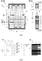
- FIG. 1 shows prior art U.S. Pat. No. 6,717,132 planar multi-reflecting TOF with gridless orthogonal pulsed accelerator OA, illustrating geometrical limits on the OA duty cycle;
- FIG. 2 shows prior art U.S. Pat. No. 7,504,620 planar multi-turn TOF with OA; both analyzer geometry and laminated sectors do limit the ion packet width and the OA duty cycle;
- FIG. 3 shows an OA-MRTOF embodiment of the present invention, improving the duty cycle of an elongated OA by ion beam confinement, spatial z-focusing of ion packets and by making the OA transparent to reflected ions;
- FIG. 4 shows a schematic of the electronic for pulsed ion acceleration and an example of a low capacitance OA built using ceramic printed circuit boards;
- FIG. 5 shows an OA-MTTOF embodiment of the present invention, improving the duty cycle of an orthogonal pulsed converter
- FIG. 6 illustrates various methods of ion beam spatial confinement within the storage gap of the elongated orthogonal accelerator
- FIG. 7 illustrates an embodiment of ion packet spatial focusing in the z-direction
- FIG. 8 shows an MRTOF embodiment of the present invention with an RF ion trap OA, improving space charge capacity of the trap by substantial trap elongation, followed by ion packets spatial focusing towards the detector.
- FIG. 1 shows a multi-reflecting TOF with an orthogonal accelerator (OA-MRTOF) 10 according to U.S. Pat. No. 6,717,132.
- the MRTOF 10 comprises: an ion source 11 with a lens system 12 to form a substantially parallel ion beam 13 ; an orthogonal accelerator (OA) 15 with a storage gap 14 to admit the ion beam 13 ; a pair of gridless ion mirrors 18 separated by a field-free drift region, and a detector 19 .
- OA-MRTOF orthogonal accelerator
- Both the OA 15 and mirrors 18 are formed with plate electrodes having slit openings, oriented in the Z-direction, thus forming a two dimensional electrostatic field, characterized by symmetry about the XZ-symmetry plane, denoted as s-XZ. All of the storage gap 14 , the plates of the OA 15 , the ion mirrors 18 and the detector 19 are aligned parallel to the drift axis Z.
- Gaseous ion sources (like ESI, APCI, APPI, gaseous MALDI or ICP) comprise gas-filled radio-frequency (RF) ion guides (not shown) for dampening of the ion beams, followed by a lens 12 to form a substantially parallel continuous ion beam 13 .
- RF radio-frequency
- Typical ion beam parameters are: lmm diameter, 1 degree angular divergence at a specific ion energy (energy per charge) U Z of from 10 to 50V at typical axial energy spread of 1 eV.
- the beam 13 propagates in the Z-direction through storage gap 14 , which is a field-free region between plate electrodes. Periodically, an electrical pulse is applied between the plates defining the storage gap 14 . A portion of the continuous ion beam 13 , in the storage gap 14 , is accelerated in the X-direction by a pulsed field and is accelerated to specific energy U X , thus forming a ribbon-shaped ion packet 16 travelling along the mean ion trajectory 17 .
- Ion packets 16 are reflected by ion mirrors 18 in the X-direction, and continue to slowly drift in the Z-direction, and arrive on detector 19 after multiple N ion mirror reflections during a jigsaw shaped ion trajectory 17 .
- the useful length of each ion packet L Z becomes limited to: L Z ⁇ D Z /N (eq. 2) where D Z is the distance in the Z-dimension from the most upstream point of the OA 15 that ions are ejected from to the mid-point of the detector 19 at which ions are detected.
- the ion packet length L Z is therefore under 30 mm.
- ⁇ * defines the heaviest specific mass in the beam 13 .
- the OA-MRTOF instrument has a low duty cycle.
- the duty cycle limit occurs due to the ion trajectory arrangement within the s-XZ symmetry plane of mirrors 18 and OA 15 .
- the alignment of the ion trajectory within the s-XZ XZ plane is forced to keep the isochronous properties of the ion mirrors and gridless OA, reaching up to third order full isochronicity as described in WO2014142897.
- the prior art MRTOF 10 has been designed with recognition of the symmetry requirements.
- the duty cycle is sacrificed in exchange for higher resolving power of OA-MRTOF.
- FIG. 2 shows a multi-turn TOF analyzer having an orthogonal accelerator (OA-MTTOF) 20 according to U.S. Pat. No. 7,504,620.
- the MTTOF 20 comprises: an ion source 11 with a lens system 12 to form a substantially parallel ion beam 13 ; an orthogonal accelerator (OA) 15 with a storage gap 14 to admit the beam 13 ; four laminated electrostatic sectors 28 , separated by field-free drift regions, and a TOF detector 19 .
- OA-MTTOF orthogonal accelerator
- the OA 15 in FIG. 2 admits a slow (say, 10 eV) ion beam 13 and periodically ejects ion packets 26 along the ion trajectory 27 .
- Electrostatic sectors 28 are arranged isochronously for a spiral ion trajectory 27 with a figure-of-eight shaped ion trajectory in the XY-plane and with a slow advancing in the drift Z-direction due to the fixed inclination angle ⁇ at which the sectors 28 are arranged.
- the energy of ion beam 13 and the OA acceleration voltage are arranged to match the inclination angle ⁇ of the laminated sectors.
- the laminated sectors 28 provide three dimensional electrostatic fields for ion packet confinement in the drift Z-direction along the mean spiral trajectory 27 .
- the fields of the four electrostatic sectors 28 also provide for isochronous ion oscillations along the figure-of-eight shaped central curved ion trajectory 27 in the XY-plane, also denoted as s.
- These sector analyzers are known to provide so-called triple focusing, i.e. first-order focusing with respect to energy spread around a mean ion energy and with respect to angular and spatial spread of ion packets around the mean ion trajectory.
- the sector MTTOF isochronicity has been recently improved with electrostatic sectors of non-equal radii, as described in WO2017042665.
- the ion trajectory in the MTTOF 20 is locked to the fixed spiral trajectory 27 ( s ), which forces the sequential arrangement of the OA 15 , sectors 28 and of the detector 19 , thus limiting the duty cycle of the OA to being under 1/N, where N is the number of full turns.
- the length L Z of ion packets 26 in the Z-dimension shall be at least twice as small as the width in the Z-dimension of each laminated channel in the sectors, and hence, the duty cycle of the MTTOF 20 is limited as described by eq.3 above.
- Embodiments of the present invention provide a method and apparatus for improving the duty cycle of orthogonal accelerators (OA) for multi-pass MPTOF analysers, i.e. for both multi-reflecting OA-MRTOF and multi-turn OA-MTTOF analysers.
- OA orthogonal accelerators
- FIG. 3 shows an embodiment of an OA-MRTOF instrument 40 according to the present invention, in both the XZ plane (40-XZ) and the XY plane (40-XY).
- the instrument 40 comprises: a continuous ion source 11 ; a lens system 12 to form a continuous and substantially parallel ion beam 13 ; an orthogonal accelerator 30 , composed of electrodes with elongated slits 31 (elongated in the Z-dimension) the OA 30 having means for ion beam spatial confinement 32 (detailed in FIG.
- the electrodes of the OA 30 and ion mirrors 41 and 42 are substantially elongated in the drift Z-direction to provide a two-dimensional electrostatic field in the X-Y plane, that is symmetric around the s-XZ symmetry plane of isochronous trajectory surface and which has a zero field component in the Z-direction.
- the electrodes 31 of the OA 30 are made transparent for the ions being reflected back from an ion mirror 41 , 42 .
- the accelerating field of the OA 30 is pulsed during ion extraction from the OA and is switched off afterwards, so that the ions reflected by the mirrors and returning through the OA are not defocussed.
- a continuous or quasi-continuous ion source 11 generates ions.
- a substantially parallel ion beam 13 passes through ion optics 12 and enters OA 30 substantially along the Z-direction.
- the beam may be spatially confined in at least the X-direction (optionally also the Y-direction) with confinement means 32 within the z-elongated storage gap of OA 30 .
- An L Z long portion of continuous beam 13 is converted into a pulsed ion packet 35 by an orthogonal pulsed acceleration field of OA 30 , energized by pulse generator 34 .
- Ejected ion packets 35 move at some inclination angle ⁇ to the X-direction, which is controlled by the U Z specific energy of the incoming ion beam 13 and acceleration voltage U X gained at pulsed acceleration in the OA (see eq.1 above).
- the embodiment 40 employs two-dimensional Z-extended MR-TOF mirrors and an OA oriented in the Z-direction. Distinctly from FIG. 1 , the duty cycle of the MRTOF 40 according to the embodiment shown is improved by the combination of the following features:
- the distance A Z in the z-direction may be determined along the axis that is half-way (in the x-direction) between the mirrors, and based on the positions of the centre (in the z-direction) of the ion packet.
- the L Z length may be comparable to a notable portion (say, 1 ⁇ 2) of the total drift length D Z (e.g.
- the ratio L Z /A Z may be one of the group: (i) 0.5 ⁇ L Z /A Z ⁇ 1; (ii) 1 ⁇ L Z /A Z ⁇ 2; (iii) 2 ⁇ L Z /A Z ⁇ 5; (iv) 5 ⁇ L Z /A Z ⁇ 10; (v) 10 ⁇ L Z /A Z ⁇ 20; and (vi) 20 ⁇ L Z /A Z ⁇ 50.
- Means 32 may be arranged for spatial confinement of the ion beam so as to prevent the natural expansion of ion beam 13 within the OA 30 and to allow substantial (potentially indefinite) elongation of the OA without ionic losses and without ion beam spread, as detailed below in FIG. 6 .
- the ion packets 35 may be spatially focused in the Z-direction by a trans-axial lens 33 that may be within the OA 30 (or immediately downstream of the OA), or by a Fresnel lens, or by spatial space-velocity correlation of the continuous ion beam 13 within the OA, e.g. as described in co-pending applicationWO2019/030475.
- the trans-axial lens 33 may comprise focusing electrodes configured to generate an electric field region through which ions travel in use that has equipotential field lines that curve and/or diverge as a function of position along the drift Z-direction so as to focus ions in the drift Z-direction.
- the inclination angle ⁇ of ion trajectories with respect to the x-direction become dependent on z-position, as illustrated by ion packet vectors 36 having inclination angles ⁇ 1 and ⁇ 2 .
- the spatial focusing (in the z-direction) leads to ion packet confinement towards the detector 44 .
- the Z-focusing may be arranged isochronous, i.e. with compensation of T
- the ion mirrors 41 , 42 return the long ion packets 35 towards the OA 30 , as shown by trajectories A′ and B′.
- OA electrodes 31 are made transparent to the reflected ions, say, with elongated slits.
- the mass analyser is configured such that the ions pass back through the OA 30 between exiting one mirror and entering the other ion mirror (for at least some of the passes between the ion mirrors), and without the ions hitting the electrodes 31 of the OA 30 .
- the ions may pass through the OA when travelling from the final mirror reflection to the detector 44 .
- the OA electrodes 31 may comprise slits through which the ions pass as they travel between the mirrors 41 , 42 .
- Each electrode 31 may comprise a single slit through which the ions pass, and that is elongated in the Z-direction.
- the slits (and therefore the OA electrodes) may each extend for the entire Z-width of the ion trajectories within the MRTOF analyzer.
- the slits may extend from the most upstream point of the OA 30 that ions are ejected from (or from further upstream) to a point in the z-direction that is proximate the position of the detector 44 (in the z-direction) such that ions do not hit the electrodes 31 when passing through the OA 30 .
- the slits may extend to a location in the z-direction that is adjacent the upstream or downstream edge of the detector 44 .
- the slits may be substantially coincident, in the Z-direction, with the windows of the ion mirrors 41 , 42 . Examples of the slits are well seen in both the XZ and XY views of FIG. 3 .
- each slit as being a slotted aperture within an electrode 31 (i.e. each slit is fully surrounded by the electrode), it is contemplated that each slit may be defined between two separate electrode sections that are elongated in the Z-direction (i.e. the slit may not be bounded at one or both ends in the Z-direction).
- the OA 30 referred to herein is the device that receives ions and pulses them orthogonally towards an ion mirror. The ion mirrors are not part of the OA 30 .
- high voltage (e.g. 3 to 10 kV) pulses are applied to the OA electrodes 31 , as shown in FIG. 3 , while drift space 43 between the ion mirrors is grounded.
- high voltage generators such as those built of Behlke switches
- the potentials of the OA 30 are returned to ground (optionally except for small potentials on optional ion guide 32 ) before the ions are reflected back through the OA 30 .
- the ion packets may therefore pass through the slits of the OA electrodes 31 without being defocused by the OA pulses.
- Each ion packet 35 may be allowed to reach the detector 44 before the next ion packet is pulsed.
- one or more further ion packets may be pulsed out of the OA before the ions in the preceding ion packet(s) have reached the detector 44 .
- each of these OA pulses may be times such that ions from the previous pulse(s) are not within the OA 30 at the time it is pulsed.
- the average inclination angle ⁇ is set to ⁇ ⁇ 30 mrad (by eq.1), i.e.
- the duty cycle for lighter ions can be further improved if using an ion guide (e.g. RF ion guide) of the ion source 11 (or between the source and OA 30 ) in a so-called “Pulsar” mode. Ions may be intermittently stored within the ion guide and released therefrom in a pulsed manner that is synchronized with the OA pulses, e.g.
- Using a long OA 30 substantially extends the mass range able to be mass analysed to match M/m (i.e. the ratio of the heaviest mass ion to the lightest mass ion) for ions simultaneously transmitted from the RF ion guide, i.e. the Pulsar mode does not limit the mass range.
- M/m i.e. the ratio of the heaviest mass ion to the lightest mass ion
- the Pulsar mode does not limit the mass range.
- the “Pulsar” gain is substantially higher for OA-MRTOF at substantially longer flight times and flight paths (say, tens and hundreds of meters).
- ions may be stored in the RF ion guide between rare OA pulses, while ion packets ejected from the ion guide may be admitted into the OA with nearly unity duty cycle and a wide mass range.
- an exemplary electronics pulse circuitry 34 is shown for energizing the multiple electrodes 31 and 32 of OA 30 .
- a positive U A accelerating voltage may be buffered by a large capacitor C A (e.g. tens of nF), and may be pulse connected to an RC dividing chain via high voltage switch 38 .
- a Behlke switch may be used, e.g. a HTS-61-05 model operating up to 6 kV, 50 A peak current and may connect a high voltage at a 40 ns rise time at capacitive loads up to a few nF.
- Capacitors C may be in the order of 10-100 pF to reduce the voltage sagging during the pulse.
- the resistors R may be in the 0.1-1MOhm range to reduce average current to well under 0.5 A, accounting for about 1% time duty cycle of pulses at a few us pulse duration and 100-300us pulse period.
- a clean pulse shape depends on stray capacitances and inductances.
- OA 39 may be made as a ceramic PCB board with conductive strips 31 , with a resistive coating in between strips, and with small and precise 10 pF size capacitors C constructed across the PCB.
- the combination of circuit 34 and PCB OA 39 is expected to provide clean fractions of pulse amplitude, here shown as 1, 0.75, 0.5 and 0.25 of pulse amplitude.
- electrodes of the OA ion guide may be pulsed from some small (say, ⁇ 10 to ⁇ 30V) negative offset.
- the offset pulses may be arranged with a separate RC dividing chain.
- FIG. 5 shows an OA-MTTOF embodiment 50 of the present invention. This is similar to the previously described embodiments, but has sectors for turning the ions rather than mirrors for reflecting the ions.
- FIG. 5 shows a view 50-XZ in the XZ plane and a view 50-XY in the XY plane.
- the analyser comprises: a (e.g.
- each of the sectors 51 and 52 may be substantially extended in the drift Z-direction (i.e. may not use lamination). This allows the ions to spiral around the device and through any given sector multiple times as the ions drift in the z-direction, as will be described below.
- Each sector may extend, in the z-direction, at least from the most upstream point of the OA 15 that ions are ejected from to the detector 54 .
- the beam 13 may initially be oriented along the Z-direction.
- orthogonal accelerator 30 receives (e.g. continuous) ion beam 13 within a Z-elongated storage gap, wherein means 32 may be provided to confine the ion beam at least in the X-direction (and optionally the y-direction), as detailed in FIG. 6 below.
- OA 30 accelerates a portion of ion beam 13 by electrical pulses from generator 34 in the X-direction, thus forming ion packets 35 (denoted 55 within the analyzer). Ion packets 35 move at some mean inclination angle ⁇ to the x-direction, controlled by the specific energy of the ion beam 13 .
- Trans-axial lens 33 in the OA 30 may be arranged for spatial focusing of ion packets 35 in the Z-direction as they travel towards the detector 54 , so that the inclination angle in the MTTOF analyzer becomes dependent on the initial z-position within ion packets. Due to the z-energy of the continuous ion beam 13 , the ion packets 55 follow the spiral ion trajectory shown by rays A-B as they pass around the sectors 51 , 52 and within the mean trajectory surface S to provide for at least first order full isochronicity, while slowly converging in the Z-direction towards detector 54 .
- sectors 51 and 52 have different radii, as described in WO2017042665 to provide for higher order isochronicity.
- the sectors of the MTTOF in embodiment 50 may not have any electrostatic field component in the Z-direction, which would otherwise affect the spiral motion.
- the stadium shaped ion trajectory s-surface is arranged between electrostatic sectors 51 and 52 , separated by grounded field-free regions 53 .
- the sectors XY-field and ion packet energy in the X-direction may be adjusted for isochronous ion packet motion within the trajectory surface S.
- the inclination angle ⁇ is controlled by the ion beam 13 energy and by Z-focusing means 32 only.
- the length L Z of the ion packets 35 may be made comparable (say 1 ⁇ 2) of the total drift length D Z .
- the ion packet length L Z appears much longer than the ion packet advance A Z per single turn.
- embodiment 50 of FIG. 5 employs similar ion optical methods for: the OA elongation, ion beam confinement within the OA, Z-focusing of ion packets, making long slits in the OA electrodes, and pulsed switching off the OA potentials for return ion packet passage through the OA.
- the ion beam emittance is still finite (about 1 mm*deg at 10 eV), and the ion beam would naturally diverge by several mm within 100 mm along OA. This would compromise the combination of time and energy spreads of ion packets, affecting MPTOF resolution.
- embodiments 61, 63, 65, and 67 present generalized means 32 for the spatial confinement of ion beam 13 within the gridless orthogonal accelerator OA 30 .
- slit electrodes 31 of the gridless OA 30 are energized by pulse generator 34 to convert the continuous ion beam 13 into pulsed ion packets 35 .
- the embodiments in FIG. 6 differ from each other by the applied electrical signals and by the shape of ion confining electrodes 62 , 64 , 66 , and 68 .
- Embodiment 61 employs a rectilinear RF ion guide similar to U.S. Pat. No. 5,763,878.
- RF signals are applied to electrodes 62 so as to generate a quadrupolar RF field, radially confining ion beam 13 as it travels in the z-direction along the OA 30 .
- Embodiment 61 has drawbacks: (i) RF confinement is mass dependent; (ii) the RF field must be turned off before the acceleration pulse within microseconds, where an RF signal decay is incomplete; (iii) pulses applied to electrodes are known to excite a resonant generator of the RF signal; and (iv) the initial ion position and initial velocity are mass and RF-phase dependent, which affect resolution, mass accuracy and angular losses in TOF analyzers.
- Embodiment 63 employs a rectilinear electrostatic quadrupolar lens, formed by applying negative DC potentials to electrodes 64 , as proposed in RU2013149761.
- a weak electrostatic quadrupolar field focuses and confines the ion beam in the critical TOF X-direction, while defocusing the ion beam in the non-critical transverse Y-direction.
- the method allows lossless ion beam transfer for up to L Z ⁇ 50 mm.
- Embodiment 65 employs the spatially alternated electrostatic DC quadrupolar field along the Z-axis by alternating the polarity on DC electrodes 66 , as in co-pending application WO2019/030475.
- the embodiment provides for indefinite ion beam confinement in both X and Y directions, although a variable central potential along the Z-axis may have a negative effect on ion beam packet focusing in the Z-direction.
- Embodiment 67 provides for ion beam spatial confinement by spatial alternation of electrostatic quadrupolar field, now achieved without spatial modulation of the center-line potential U(z).
- the field is formed by an array of alternating DC dipoles 68 , as described in co-pending application WO2019/030475.
- the average potential (DC1+DC2)/2 is slightly negative to form a combination of the alternated quadrupolar field with a weak static quadrupolar field, thus providing somewhat stronger compression of the ion beam 13 in the X-direction Vs Y-direction.
- the electrostatic confinement 67 provides multiple advantages: (i) it is mass independent; (ii) it does not require resonant RF circuits and can be readily switched off; (iii) the strength and shape of the transverse confining field can be readily varied along the guide length; (iv) it can provide axial gradient of the guide potential without constructing complex RF circuits.
- Ion packet Z-focusing may be provided as detailed in co-pending application WO2019/030475, such as by the following means:
- a trans-axial (TA) lens may be incorporated into the exit lens of a gridless OA (focusing in the Y-direction).
- the TA-lens may be compensated by a slight curvature of the accelerating field around the continuous ion beam.
- Such compensating curvature of the accelerating field may be achieved for example by TA curvature of the next extracting electrode or by an even yet slighter TA-curvature of the first push electrode.
- the TA-lens and the TA-compensator may be arranged for at least the Z-length of the extracted ion packet and they may be turned off by removing the pulsed OA voltages during the ion packet return passage through the OA.
- the TA-lens may be combined with a TA-wedge for compensating non-intended misalignments of the OA and of the analyzer;
- a Fresnel lens achieved with a multi-segmented deflector, which is energized with a gradient step voltage between thin deflecting plates may be provided.
- the Fresnel lens also allows arranging wedge fields with a constant bias applied to all deflecting segments, this way serving as a compensator for mechanical misalignments.
- the Fresnel lens may be arranged at least for the z-length of extracted ion packets and may be switched off together with the OA to allow a non-distorted return ion passage;
- (C) Z-focusing may be provided by spatial-temporal correlations within a continuous ion beam, which is described below.
- Ion packet auto-focusing may be obtained by controlling and correlating the axial velocity V Z of the continuous ion beam with its z-position within the OA. In this case the OA does not need means for spatial Z-focusing 33.
- the z-directional speed of the ions may be caused to be different as a function of their z-directional position within the OA.
- Ions arranged within the OA at locations progressively further away from the detector (in the z-direction) may be given progressively higher z-directional speeds towards the detector such that the ion packet is compressed in the z-direction by the time that it reaches the detector.
- the z-dependent specific energy per charge U(z) may be caused to be different as a function of their z-directional position within the instrument. Ions arranged at locations progressively further away from the detector (in the z-direction) may be given progressively higher specific energy per charge U(z) in a direction towards the detector such that the ion packet is compressed in the z-direction by the time that it reaches the detector.
- the embodiment 70 comprises the MRTOF 40 of FIG. 3 with an orthogonal accelerator 30 , but may not have the TA-lens 33 ; and may have at least one beam correlating feature of the group: (i) an ion source 73 with a time variable acceleration bias U Z (t); (ii) an RF ion guide 74 with a time variable DC acceleration bias and/or with an electrode structure for switching an axial field gradient within the RF ion guide to different values; (iii) an extraction electrode 75 , connected to a pulse supply 76 ; (iv) an extraction electrode 75 , connected to a time variable power supply 77 ; and (v) a supply 78 for arranging a DC gradient within the ion guide 60 of the OA 30 .
- Those beam correlating features are synchronized with pulse generator 34 of the OA 30 .
- substantially elongated ion beam 33 may be retained within long OA 30 by spatial confinement means 60 , e.g. as described in relation to FIG. 6 .
- spatial confinement means 60 e.g. as described in relation to FIG. 6 .
- Neither the OA nor MRTOF Z-focus the ions, and the orthogonal ion X-motion in the MRTOF (or MTTOF) does not affect the ion Z-motion, which is instead defined by the axial ion velocity within the OA, and hence by correlations V(z) or U(z) within continuous ion beam would control ion packet Z-auto-focusing.
- an acceleration pulse 76 is applied to RF ion guide 74 (for example, a segmented quadrupole, or quadrupole with auxiliary electrodes, or an ion tunnel ion guide), thus forming a pulsed axial Z-field.
- RF ion guide 74 for example, a segmented quadrupole, or quadrupole with auxiliary electrodes, or an ion tunnel ion guide
- a negative pulse 76 may be applied to gate 75 , to follow a Pulsar method such as that described herein above.
- the pulse 76 amplitude and the length of axial Z-field within the guide 74 are arranged for time-of-flight compression of ion packets in the z-direction by the time the ions reach the detector 44 plane, located at distance D Z .
- Ions located at the entrance of the axial acceleration Z-field when it is pulsed on will arrive at the OA 30 at a later time then ions located towards the exit of the axial acceleration Z-field when it is pulsed on.
- the ions that were initially located at the entrance of the axial acceleration Z-field will have a larger speed in the z-direction V Z by the time they enter the OA, as compared to ions that were initially located further from the entrance of the axial acceleration Z-field.
- the desired negative Z-V Z correlation occurs for a mass range only, where ⁇ range is controlled by the time delay between pulse 76 and OA pulse 79 . This embodiment is attractive for target analysis, where a narrow mass range is selected intentionally, while TOF data may be acquired at maximal OA frequency and dynamic range of the detector.
- the potential of a field-free elevator is controlled by the time variable floating U(t) 77 of either ion guide 74 , or of ion optics downstream of the guide 74 .
- the voltage at which the ion guide 74 or ion optics is floated may be varied with time so as to achieve the above described bunching effect (in the z-direction), though the elevator exit may be set closer to the OA entrance and allows a somewhat wider ⁇ range to be accelerated by the OA.
- the beam 33 is slowed down within the confinement means 60 by arranging a Z-dependent axial potential distribution U(z) 78 , e.g. by a resistive divider connected to electrodes of the confinement means 60 such that different potentials are applied at different z-locations in the confinement means 60 . Then the desired z-focusing of ion packets may be achieved for the entire ionic mass range, i.e. for ions of all ⁇ . This method is particularly attractive when using the RF ion guide in the Pulsar mode, i.e. accumulating and pulse releasing ion packets from the guide 74 in a manner that is synchronized with pulses 79 of the OA.
- the OA may be a pulsed converter based on a radiofrequency (RF) ion trap with radial pulsed ejection.
- RF radiofrequency
- FIG. 8 shows an OA-MRTOF embodiment 90 of the present invention that is similar to that of FIG. 3 except that the OA is a tilted ion trap 80 and the ions are introduced into the OA along a tilted axis.
- the embodiment 90 comprises: a continuous ion source 11 generating a continuous ion beam 13 ; a multi-reflecting TOF 40 , similar to one in FIG.
- a radially ejecting (substantially in the X-direction) ion trap 80 constructed of slit electrodes 81 , energized by pulsed voltages from a generator 34 , and incorporating an ion guide 82 that is energized with a radio-frequency (RF) field for radial ion confinement.
- the electrodes of ion mirrors 41 and 42 are substantially elongated in the drift Z-direction.
- Trap 80 is elongated in the z-direction and is tilted to the Z axis by a small angle ⁇ /2 (say 1-2 degrees).
- Trap 80 may comprise a trans-axial wedge and lens 83 and a trans-axial lens 84 for ion z-focusing and for adjusting the ion steering of the mean ion trajectory by an average angle of ⁇ /2.
- Trap 80 is made of electrodes with slits, so it is transparent for ions at their return passage, as described above with respect to the OA.
- an ion source 11 In operation, an ion source 11 generates continuous or quasi-continuous (e.g. time-modulated within RF ion guide of the interface) ion beam 13 .
- Beam 13 enters and get trapped within ion guide 82 by a radial confining RF field and by using electrostatic blocking potentials at one or both z-directional ends of the ion guide 82 , for example, produced by a DC or pulsed bias of a segment of the ion guide 82 .
- Ions may be trapped as a ribbon, optionally dampened with a pulsed gas admission.
- an ion ribbon is accelerated by pulsed application of voltages by the generator 34 and the ions are urged orthogonally to electrodes 81 so as to travel at an inclination angle ⁇ /2 relative to the X-axis.
- a wedge shaped field of TA-lens 84 steers ions forward for another ⁇ /2 angle, so that ion packets 85 are parallel to the Z-direction.
- the wedge 84 may also have a lens component for ion packet z-focusing, whose time aberrations may be compensated for by a weaker TA-wedge 83 .
- ion packets 85 are aligned parallel to the Z-axis and move at an inclination angle ⁇ to the z-direction.
- the ions pass through the slits of the switched off trap 80 .
- Spatially focused (in the z-direction by lens 84 ) ion packets eventually reach the detector 44 after multiple mirror reflections, thus, improving MRTOF (or MTTOF in embodiments using sectors rather than mirrors) resolution.
- trap 80 is capable of nearly 100% duty cycle within a wide mass range, but on the other hand may introduce several parasitic effects, such as RF phase and mass dependent parameters of ion packets, oscillations of trapping RF voltage induced by pulse pick up, and larger time and energy spreads of ion packets relative to the OA-MRT in FIG. 3 .
- Substantial elongation of the novel (transparent) trap converter notably improves space charge capacity of the trap and of the MPTOF analyzer.
- the mass analyser is an MRTOF or a MTTOF
- the mass analyser may instead only have a single ion mirror or sector that reflects or turns the ions, respectively, onto the detector.
- the OA electrodes in the specific embodiments have been described as being transparent to the ions by providing them with slits, it is contemplated that the electrodes may instead be provided as mesh electrodes or with mesh portions through which the ions pass.
- the OA electrodes and their slits extend in the drift direction (z-direction) from an upstream end of the orthogonal accelerator to a point proximate or downstream of the detector.
- the OA electrodes and their slits may not extend, in the drift direction (z-direction), all of the way to the detector. Rather, there may be a gap, in the drift direction (z-direction), between the downstream end of the OA electrodes and the detector.
- each slit is defined between separate elongated electrode portions (separated in the y-direction) rather than a slot in an electrode.
Landscapes
- Chemical & Material Sciences (AREA)
- Analytical Chemistry (AREA)
- Other Investigation Or Analysis Of Materials By Electrical Means (AREA)
- Electron Tubes For Measurement (AREA)
Abstract
Description
-
- (a) an ion source, generating an ion beam along a first drift Z-direction;
- (b) an orthogonal accelerator with spatial confinement means and with electrodes connected to pulsed supplies for admitting said ion beam into a storage gap, for retaining ion beam within said confinement means and for pulsed accelerating a portion of said ion beam in the second orthogonal X-direction, thus forming ion packets;
- (c) isochronous means for ion packet focusing in said Z-direction towards a detector, arranged either within or immediately after said orthogonal accelerator;
- (d) an electrostatic multi-pass (multi-reflecting or multi-turn) time-of-flight mass analyzer (MPTOF), built of parallel ion mirrors or electrostatic sectors, separated by a drift space and substantially elongated in the Z-direction to form an electrostatic field in an orthogonal XY-plane; said two-dimensional field provides for a field-free ion drift in the Z-direction towards a detector, and for an isochronous repetitive multi-pass ion motion within an isochronous mean ion trajectory s-surface—either symmetry s-XY plane of said ion mirrors or curved s-surface of electrostatic sectors; wherein said s-surface is aligned with the symmetry plane of said accelerator and of said z-focusing means; and
- (e) wherein electrodes of said orthogonal accelerator comprise slits, transparent for return ion passage after at least one reflection or turn.
-
- (a) generating an ion beam along a first drift Z-direction in an ion source;
- (b) admitting said ion beam into a storage gap of an orthogonal accelerator, spatially confining said ion beam within said storage gap, and pulsed accelerating a portion of said ion beam in the second orthogonal X-direction, thus forming ion packets;
- (c) ion packet focusing in said Z-direction towards a detector, arranged at or immediately after said orthogonal accelerator step;
- (d) in an orthogonal XY-plane, arranging two dimensional electrostatic fields of multi-pass (multi-reflecting or multi-turn) time-of-flight mass analyzer (MPTOF), substantially elongated in the Z-direction; said two-dimensional fields provide for a field-free ion drift in the Z-direction towards a detector, and for an isochronous repetitive multi-pass ion motion within an isochronous mean ion trajectory s-surface—either symmetry s-XY plane of said ion mirrors or curved s-surface of electrostatic sectors; wherein said s-surface is aligned with the symmetry plane of electric fields at said acceleration and said z-focusing steps; and
- (e) Wherein said fields of orthogonal accelerator are arranged with transparent electrodes for non destructing and non defocusing return ion passage after at least one reflection or turn.
-
- (a) an ion source, generating an ion beam;
- (b) a radio-frequency ion trap converter, substantially elongated in the first Z-direction and ejecting ion packets substantially along the second orthogonal X-direction;
- (c) means for steering and focusing of ion packets within or immediately past said trap converter;
- (d) an electrostatic multi-pass (multi-reflecting or multi-turn) time-of-flight mass analyzer (MPTOF), built of parallel ion mirrors or electrostatic sectors, separated by a drift space and substantially elongated in the Z-direction to form an electrostatic field in an orthogonal XY-plane; said two-dimensional field provides for a field-free ion drift in the Z-direction towards a detector, and for an isochronous repetitive multi-pass ion motion within an isochronous mean ion trajectory s-surface—either symmetry s-XY plane of said ion mirrors or curved s-surface of electrostatic sectors; wherein said s-surface is aligned with the symmetry plane of said pulsed converter and of said z-focusing means; and
- (e) wherein electrodes of said trap converter comprise slits, transparent for return ion passage after at least one reflection or turn.
- (a) an ion source, generating an ion beam;
a=(U Z /U X)0.5 (eq.1)
L Z <D Z /N (eq. 2)
where DZ is the distance in the Z-dimension from the most upstream point of the
DC=sqrt(μ/μ*)L Z /D Z, <sqrt(μ/μ*)/2N (eq.3)
| TABLE 1 | |||||||||
| DX | DZ | UX | UZ | α | AZ | L | LZ | DC | |
| mm | mm | V | V | mrad | mm | N refl | m | mm | % |
| 1000 | 300 | 10000 | 10 | 30 | 30 | 10 | 10 | 150 | 50 |
Claims (19)
Applications Claiming Priority (4)
| Application Number | Priority Date | Filing Date | Title |
|---|---|---|---|
| GBGB1810573.4A GB201810573D0 (en) | 2018-06-28 | 2018-06-28 | Multi-pass mass spectrometer with improved duty cycle |
| GB1810573 | 2018-06-28 | ||
| GB1810573.4 | 2018-06-28 | ||
| PCT/GB2019/051839 WO2020002940A1 (en) | 2018-06-28 | 2019-06-28 | Multi-pass mass spectrometer with high duty cycle |
Publications (2)
| Publication Number | Publication Date |
|---|---|
| US20210134581A1 US20210134581A1 (en) | 2021-05-06 |
| US11587779B2 true US11587779B2 (en) | 2023-02-21 |
Family
ID=63143515
Family Applications (1)
| Application Number | Title | Priority Date | Filing Date |
|---|---|---|---|
| US17/256,258 Active 2039-09-21 US11587779B2 (en) | 2018-06-28 | 2019-06-28 | Multi-pass mass spectrometer with high duty cycle |
Country Status (5)
| Country | Link |
|---|---|
| US (1) | US11587779B2 (en) |
| EP (1) | EP3815130A1 (en) |
| CN (1) | CN112514029B (en) |
| GB (1) | GB201810573D0 (en) |
| WO (1) | WO2020002940A1 (en) |
Cited By (1)
| Publication number | Priority date | Publication date | Assignee | Title |
|---|---|---|---|---|
| US20240230590A1 (en) * | 2021-05-14 | 2024-07-11 | Universitätsmedizin Der Johannes Gutenberg-Universität Mainz | Method and apparatus for combined ion mobility and mass spectrometry analysis |
Families Citing this family (19)
| Publication number | Priority date | Publication date | Assignee | Title |
|---|---|---|---|---|
| GB201613988D0 (en) | 2016-08-16 | 2016-09-28 | Micromass Uk Ltd And Leco Corp | Mass analyser having extended flight path |
| GB2567794B (en) | 2017-05-05 | 2023-03-08 | Micromass Ltd | Multi-reflecting time-of-flight mass spectrometers |
| GB2563571B (en) | 2017-05-26 | 2023-05-24 | Micromass Ltd | Time of flight mass analyser with spatial focussing |
| US11295944B2 (en) | 2017-08-06 | 2022-04-05 | Micromass Uk Limited | Printed circuit ion mirror with compensation |
| US11081332B2 (en) | 2017-08-06 | 2021-08-03 | Micromass Uk Limited | Ion guide within pulsed converters |
| US11239067B2 (en) | 2017-08-06 | 2022-02-01 | Micromass Uk Limited | Ion mirror for multi-reflecting mass spectrometers |
| US11049712B2 (en) | 2017-08-06 | 2021-06-29 | Micromass Uk Limited | Fields for multi-reflecting TOF MS |
| CN111164731B (en) | 2017-08-06 | 2022-11-18 | 英国质谱公司 | Ion implantation into a multichannel mass spectrometer |
| WO2019030477A1 (en) | 2017-08-06 | 2019-02-14 | Anatoly Verenchikov | Accelerator for multi-pass mass spectrometers |
| WO2019030475A1 (en) | 2017-08-06 | 2019-02-14 | Anatoly Verenchikov | Multi-pass mass spectrometer |
| GB201806507D0 (en) | 2018-04-20 | 2018-06-06 | Verenchikov Anatoly | Gridless ion mirrors with smooth fields |
| GB201807605D0 (en) | 2018-05-10 | 2018-06-27 | Micromass Ltd | Multi-reflecting time of flight mass analyser |
| GB201807626D0 (en) | 2018-05-10 | 2018-06-27 | Micromass Ltd | Multi-reflecting time of flight mass analyser |
| GB201808530D0 (en) | 2018-05-24 | 2018-07-11 | Verenchikov Anatoly | TOF MS detection system with improved dynamic range |
| GB201810573D0 (en) | 2018-06-28 | 2018-08-15 | Verenchikov Anatoly | Multi-pass mass spectrometer with improved duty cycle |
| GB201901411D0 (en) | 2019-02-01 | 2019-03-20 | Micromass Ltd | Electrode assembly for mass spectrometer |
| GB201903779D0 (en) | 2019-03-20 | 2019-05-01 | Micromass Ltd | Multiplexed time of flight mass spectrometer |
| CN115360078B (en) * | 2022-08-29 | 2024-03-29 | 东南大学 | A multi-channel mass selector for isomomentum and isokinetic energy acceleration |
| GB202301462D0 (en) * | 2023-02-01 | 2023-03-15 | Micromass Ltd | Multi-reflecting TOF mass spectrometry |
Citations (344)
| Publication number | Priority date | Publication date | Assignee | Title |
|---|---|---|---|---|
| SU198034A1 (en) | Б. А. Мамырин Физико технический институт Иоффе СССР | TIME-FLIGHT MASS SPECTROMETER | ||
| US3898452A (en) | 1974-08-15 | 1975-08-05 | Itt | Electron multiplier gain stabilization |
| GB2080021A (en) | 1980-07-08 | 1982-01-27 | Wollnik Hermann | Time-of-flight Mass Spectrometer |
| US4390784A (en) | 1979-10-01 | 1983-06-28 | The Bendix Corporation | One piece ion accelerator for ion mobility detector cells |
| JPS6229049A (en) | 1985-07-31 | 1987-02-07 | Hitachi Ltd | Mass spectrometer |
| US4691160A (en) | 1983-11-11 | 1987-09-01 | Anelva Corporation | Apparatus comprising a double-collector electron multiplier for counting the number of charged particles |
| EP0237259A2 (en) | 1986-03-07 | 1987-09-16 | Finnigan Corporation | Mass spectrometer |
| US4731532A (en) | 1985-07-10 | 1988-03-15 | Bruker Analytische Mestechnik Gmbh | Time of flight mass spectrometer using an ion reflector |
| US4855595A (en) | 1986-07-03 | 1989-08-08 | Allied-Signal Inc. | Electric field control in ion mobility spectrometry |
| GB2217907A (en) | 1988-04-28 | 1989-11-01 | Jeol Ltd | Direct imaging type sims instrument having tof mass spectrometer mode |
| WO1991003071A1 (en) | 1989-08-25 | 1991-03-07 | Institut Energeticheskikh Problem Khimicheskoi Fiziki Akademii Nauk Sssr | Method and device for continuous-wave ion beam time-of-flight mass-spectrometric analysis |
| US5017780A (en) | 1989-09-20 | 1991-05-21 | Roland Kutscher | Ion reflector |
| SU1681340A1 (en) | 1987-02-25 | 1991-09-30 | Филиал Института энергетических проблем химической физики АН СССР | Method of mass-spectrometric analysis for time-of-flight of uninterrupted beam of ions |
| SU1725289A1 (en) | 1989-07-20 | 1992-04-07 | Институт Ядерной Физики Ан Казсср | Time-of-flight mass spectrometer with multiple reflection |
| US5107109A (en) | 1986-03-07 | 1992-04-21 | Finnigan Corporation | Method of increasing the dynamic range and sensitivity of a quadrupole ion trap mass spectrometer |
| US5128543A (en) | 1989-10-23 | 1992-07-07 | Charles Evans & Associates | Particle analyzer apparatus and method |
| US5202563A (en) | 1991-05-16 | 1993-04-13 | The Johns Hopkins University | Tandem time-of-flight mass spectrometer |
| GB2274197A (en) | 1993-01-11 | 1994-07-13 | Kratos Analytical Ltd | Time-of-flight mass spectrometer |
| US5331158A (en) | 1992-12-07 | 1994-07-19 | Hewlett-Packard Company | Method and arrangement for time of flight spectrometry |
| DE4310106C1 (en) | 1993-03-27 | 1994-10-06 | Bruker Saxonia Analytik Gmbh | Manufacturing process for switching grids of an ion mobility spectrometer and switching grids manufactured according to the process |
| US5367162A (en) | 1993-06-23 | 1994-11-22 | Meridian Instruments, Inc. | Integrating transient recorder apparatus for time array detection in time-of-flight mass spectrometry |
| US5396065A (en) | 1993-12-21 | 1995-03-07 | Hewlett-Packard Company | Sequencing ion packets for ion time-of-flight mass spectrometry |
| US5435309A (en) | 1993-08-10 | 1995-07-25 | Thomas; Edward V. | Systematic wavelength selection for improved multivariate spectral analysis |
| US5464985A (en) | 1993-10-01 | 1995-11-07 | The Johns Hopkins University | Non-linear field reflectron |
| GB2300296A (en) | 1995-04-26 | 1996-10-30 | Bruker Franzen Analytik Gmbh | A method for measuring the mobility spectra of ions with ion mobility spectrometers(IMS) |
| US5619034A (en) | 1995-11-15 | 1997-04-08 | Reed; David A. | Differentiating mass spectrometer |
| US5652427A (en) | 1994-02-28 | 1997-07-29 | Analytica Of Branford | Multipole ion guide for mass spectrometry |
| US5654544A (en) | 1995-08-10 | 1997-08-05 | Analytica Of Branford | Mass resolution by angular alignment of the ion detector conversion surface in time-of-flight mass spectrometers with electrostatic steering deflectors |
| US5689111A (en) | 1995-08-10 | 1997-11-18 | Analytica Of Branford, Inc. | Ion storage time-of-flight mass spectrometer |
| US5696375A (en) | 1995-11-17 | 1997-12-09 | Bruker Analytical Instruments, Inc. | Multideflector |
| WO1998001218A1 (en) | 1996-07-08 | 1998-01-15 | The Johns-Hopkins University | End cap reflectron for time-of-flight mass spectrometer |
| WO1998008244A2 (en) | 1996-08-17 | 1998-02-26 | Millbrook Instruments Limited | Charged particle velocity analyser |
| US5763878A (en) | 1995-03-28 | 1998-06-09 | Bruker-Franzen Analytik Gmbh | Method and device for orthogonal ion injection into a time-of-flight mass spectrometer |
| US5777326A (en) | 1996-11-15 | 1998-07-07 | Sensor Corporation | Multi-anode time to digital converter |
| US5834771A (en) | 1994-07-08 | 1998-11-10 | Agency For Defence Development | Ion mobility spectrometer utilizing flexible printed circuit board and method for manufacturing thereof |
| US5847385A (en) | 1996-08-09 | 1998-12-08 | Analytica Of Branford, Inc. | Mass resolution by angular alignment of the ion detector conversion surface in time-of-flight mass spectrometers with electrostatic steering deflectors |
| US5869829A (en) | 1996-07-03 | 1999-02-09 | Analytica Of Branford, Inc. | Time-of-flight mass spectrometer with first and second order longitudinal focusing |
| US5955730A (en) | 1997-06-26 | 1999-09-21 | Comstock, Inc. | Reflection time-of-flight mass spectrometer |
| US5994695A (en) | 1998-05-29 | 1999-11-30 | Hewlett-Packard Company | Optical path devices for mass spectrometry |
| US6002122A (en) | 1998-01-23 | 1999-12-14 | Transient Dynamics | High-speed logarithmic photo-detector |
| US6013913A (en) | 1998-02-06 | 2000-01-11 | The University Of Northern Iowa | Multi-pass reflectron time-of-flight mass spectrometer |
| JP2000036285A (en) | 1998-07-17 | 2000-02-02 | Jeol Ltd | Spectrum processing method of time-of-flight mass spectrometer |
| JP2000048764A (en) | 1998-07-24 | 2000-02-18 | Jeol Ltd | Time-of-flight mass spectrometer |
| US6080985A (en) | 1997-09-30 | 2000-06-27 | The Perkin-Elmer Corporation | Ion source and accelerator for improved dynamic range and mass selection in a time of flight mass spectrometer |
| US6107625A (en) | 1997-05-30 | 2000-08-22 | Bruker Daltonics, Inc. | Coaxial multiple reflection time-of-flight mass spectrometer |
| US6160256A (en) | 1997-08-08 | 2000-12-12 | Jeol Ltd. | Time-of-flight mass spectrometer and mass spectrometric method sing same |
| WO2000077823A2 (en) | 1999-06-11 | 2000-12-21 | Perseptive Biosystems, Inc. | Tandem time-of-flight mass spectometer with damping in collision cell and method for use |
| US6198096B1 (en) | 1998-12-22 | 2001-03-06 | Agilent Technologies, Inc. | High duty cycle pseudo-noise modulated time-of-flight mass spectrometry |
| US6229142B1 (en) | 1998-01-23 | 2001-05-08 | Micromass Limited | Time of flight mass spectrometer and detector therefor |
| US6271917B1 (en) | 1998-06-26 | 2001-08-07 | Thomas W. Hagler | Method and apparatus for spectrum analysis and encoder |
| US20010011703A1 (en) | 2000-02-09 | 2001-08-09 | Jochen Franzen | Gridless time-of-flight mass spectrometer for orthogonal ion injection |
| EP1137044A2 (en) | 2000-03-03 | 2001-09-26 | Micromass Limited | Time of flight mass spectrometer with selectable drift lenght |
| US6300626B1 (en) | 1998-08-17 | 2001-10-09 | Board Of Trustees Of The Leland Stanford Junior University | Time-of-flight mass spectrometer and ion analysis |
| US20010030284A1 (en) | 1995-08-10 | 2001-10-18 | Thomas Dresch | Ion storage time-of-flight mass spectrometer |
| US6316768B1 (en) | 1997-03-14 | 2001-11-13 | Leco Corporation | Printed circuit boards as insulated components for a time of flight mass spectrometer |
| US6337482B1 (en) | 2000-03-31 | 2002-01-08 | Digray Ab | Spectrally resolved detection of ionizing radiation |
| US20020030159A1 (en) | 1999-05-21 | 2002-03-14 | Igor Chernushevich | MS/MS scan methods for a quadrupole/time of flight tandem mass spectrometer |
| US6384410B1 (en) | 1998-01-30 | 2002-05-07 | Shimadzu Research Laboratory (Europe) Ltd | Time-of-flight mass spectrometer |
| US6393367B1 (en) | 2000-02-19 | 2002-05-21 | Proteometrics, Llc | Method for evaluating the quality of comparisons between experimental and theoretical mass data |
| US20020107660A1 (en) | 2000-09-20 | 2002-08-08 | Mehrdad Nikoonahad | Methods and systems for determining a critical dimension and a thin film characteristic of a specimen |
| US6437325B1 (en) | 1999-05-18 | 2002-08-20 | Advanced Research And Technology Institute, Inc. | System and method for calibrating time-of-flight mass spectra |
| US6455845B1 (en) | 2000-04-20 | 2002-09-24 | Agilent Technologies, Inc. | Ion packet generation for mass spectrometer |
| DE10116536A1 (en) | 2001-04-03 | 2002-10-17 | Wollnik Hermann | Flight time mass spectrometer has significantly greater ion energy on substantially rotation symmetrical electrostatic accelerating lens axis near central electrodes than for rest of flight path |
| US6469295B1 (en) | 1997-05-30 | 2002-10-22 | Bruker Daltonics Inc. | Multiple reflection time-of-flight mass spectrometer |
| US6489610B1 (en) | 1998-09-25 | 2002-12-03 | The State Of Oregon Acting By And Through The State Board Of Higher Education On Behalf Of Oregon State University | Tandem time-of-flight mass spectrometer |
| US20020190199A1 (en) | 2001-06-13 | 2002-12-19 | Gangqiang Li | Grating pattern and arrangement for mass spectrometers |
| US6504150B1 (en) | 1999-06-11 | 2003-01-07 | Perseptive Biosystems, Inc. | Method and apparatus for determining molecular weight of labile molecules |
| US6504148B1 (en) | 1999-05-27 | 2003-01-07 | Mds Inc. | Quadrupole mass spectrometer with ION traps to enhance sensitivity |
| US20030010907A1 (en) | 2000-05-30 | 2003-01-16 | Hayek Carleton S. | Threat identification for mass spectrometer system |
| JP2003031178A (en) | 2001-07-17 | 2003-01-31 | Anelva Corp | Quadrupole mass spectrometer |
| US6545268B1 (en) | 2000-04-10 | 2003-04-08 | Perseptive Biosystems | Preparation of ion pulse for time-of-flight and for tandem time-of-flight mass analysis |
| US6580070B2 (en) | 2000-06-28 | 2003-06-17 | The Johns Hopkins University | Time-of-flight mass spectrometer array instrument |
| US20030111597A1 (en) | 2001-12-19 | 2003-06-19 | Ionwerks, Inc. | Multi-anode detector with increased dynamic range for time-of-flight mass spectrometers with counting data acquisition |
| US6591121B1 (en) | 1996-09-10 | 2003-07-08 | Xoetronics Llc | Measurement, data acquisition, and signal processing |
| US6614020B2 (en) | 2000-05-12 | 2003-09-02 | The Johns Hopkins University | Gridless, focusing ion extraction device for a time-of-flight mass spectrometer |
| US6627877B1 (en) | 1997-03-12 | 2003-09-30 | Gbc Scientific Equipment Pty Ltd. | Time of flight analysis device |
| US6646252B1 (en) | 1998-06-22 | 2003-11-11 | Marc Gonin | Multi-anode detector with increased dynamic range for time-of-flight mass spectrometers with counting data acquisition |
| US6647347B1 (en) | 2000-07-26 | 2003-11-11 | Agilent Technologies, Inc. | Phase-shifted data acquisition system and method |
| US6664545B2 (en) | 2001-08-29 | 2003-12-16 | The Board Of Trustees Of The Leland Stanford Junior University | Gate for modulating beam of charged particles and method for making same |
| US20030232445A1 (en) | 2002-01-18 | 2003-12-18 | Newton Laboratories, Inc. | Spectroscopic diagnostic methods and system |
| GB2390935A (en) | 2002-07-16 | 2004-01-21 | Anatoli Nicolai Verentchikov | Time-nested mass analysis using a TOF-TOF tandem mass spectrometer |
| US6683299B2 (en) | 2001-05-25 | 2004-01-27 | Ionwerks | Time-of-flight mass spectrometer for monitoring of fast processes |
| US20040026613A1 (en) | 2002-05-30 | 2004-02-12 | Bateman Robert Harold | Mass spectrometer |
| US6694284B1 (en) | 2000-09-20 | 2004-02-17 | Kla-Tencor Technologies Corp. | Methods and systems for determining at least four properties of a specimen |
| US20040084613A1 (en) | 2001-04-03 | 2004-05-06 | Bateman Robert Harold | Mass spectrometer and method of mass spectrometry |
| US6734968B1 (en) | 1999-02-09 | 2004-05-11 | Haiming Wang | System for analyzing surface characteristics with self-calibrating capability |
| US6737642B2 (en) | 2002-03-18 | 2004-05-18 | Syagen Technology | High dynamic range analog-to-digital converter |
| US6744042B2 (en) | 2001-06-18 | 2004-06-01 | Yeda Research And Development Co., Ltd. | Ion trapping |
| US6744040B2 (en) | 2001-06-13 | 2004-06-01 | Bruker Daltonics, Inc. | Means and method for a quadrupole surface induced dissociation quadrupole time-of-flight mass spectrometer |
| US20040108453A1 (en) | 2002-11-22 | 2004-06-10 | Jeol Ltd. | Orthogonal acceleration time-of-flight mass spectrometer |
| US20040119012A1 (en) | 2002-12-20 | 2004-06-24 | Vestal Marvin L. | Time-of-flight mass analyzer with multiple flight paths |
| GB2396742A (en) | 2002-10-19 | 2004-06-30 | Bruker Daltonik Gmbh | A TOF mass spectrometer with figure-of-eight flight path |
| US20040144918A1 (en) | 2002-10-11 | 2004-07-29 | Zare Richard N. | Gating device and driver for modulation of charged particle beams |
| US6770870B2 (en) | 1998-02-06 | 2004-08-03 | Perseptive Biosystems, Inc. | Tandem time-of-flight mass spectrometer with delayed extraction and method for use |
| US20040155187A1 (en) | 2001-05-04 | 2004-08-12 | Jan Axelsson | Fast variable gain detector system and method of controlling the same |
| US6782342B2 (en) | 2001-06-08 | 2004-08-24 | University Of Maine | Spectroscopy instrument using broadband modulation and statistical estimation techniques to account for component artifacts |
| US6787760B2 (en) | 2001-10-12 | 2004-09-07 | Battelle Memorial Institute | Method for increasing the dynamic range of mass spectrometers |
| US6794643B2 (en) | 2003-01-23 | 2004-09-21 | Agilent Technologies, Inc. | Multi-mode signal offset in time-of-flight mass spectrometry |
| US20040183007A1 (en) | 2003-03-21 | 2004-09-23 | Biospect, Inc. | Multiplexed orthogonal time-of-flight mass spectrometer |
| JP3571546B2 (en) | 1998-10-07 | 2004-09-29 | 日本電子株式会社 | Atmospheric pressure ionization mass spectrometer |
| US6804003B1 (en) | 1999-02-09 | 2004-10-12 | Kla-Tencor Corporation | System for analyzing surface characteristics with self-calibrating capability |
| US6815673B2 (en) | 2001-12-21 | 2004-11-09 | Mds Inc. | Use of notched broadband waveforms in a linear ion trap |
| US6833544B1 (en) | 1998-12-02 | 2004-12-21 | University Of British Columbia | Method and apparatus for multiple stages of mass spectrometry |
| GB2403063A (en) | 2003-06-21 | 2004-12-22 | Anatoli Nicolai Verentchikov | Time of flight mass spectrometer employing a plurality of lenses focussing an ion beam in shift direction |
| US6836742B2 (en) | 2001-10-25 | 2004-12-28 | Bruker Daltonik Gmbh | Method and apparatus for producing mass spectrometer spectra with reduced electronic noise |
| US6841936B2 (en) | 2003-05-19 | 2005-01-11 | Ciphergen Biosystems, Inc. | Fast recovery electron multiplier |
| US20050006577A1 (en) | 2002-11-27 | 2005-01-13 | Ionwerks | Fast time-of-flight mass spectrometer with improved data acquisition system |
| US20050040326A1 (en) | 2003-03-20 | 2005-02-24 | Science & Technology Corporation @ Unm | Distance of flight spectrometer for MS and simultaneous scanless MS/MS |
| US6861645B2 (en) | 2002-10-14 | 2005-03-01 | Bruker Daltonik, Gmbh | High resolution method for using time-of-flight mass spectrometers with orthogonal ion injection |
| US6864479B1 (en) | 1999-09-03 | 2005-03-08 | Thermo Finnigan, Llc | High dynamic range mass spectrometer |
| US6870156B2 (en) | 2002-02-14 | 2005-03-22 | Bruker Daltonik, Gmbh | High resolution detection for time-of-flight mass spectrometers |
| US6870157B1 (en) | 2002-05-23 | 2005-03-22 | The Board Of Trustees Of The Leland Stanford Junior University | Time-of-flight mass spectrometer system |
| US6872938B2 (en) | 2001-03-23 | 2005-03-29 | Thermo Finnigan Llc | Mass spectrometry method and apparatus |
| US6888130B1 (en) | 2002-05-30 | 2005-05-03 | Marc Gonin | Electrostatic ion trap mass spectrometers |
| WO2005043575A2 (en) | 2003-10-20 | 2005-05-12 | Ionwerks, Inc. | A time-of-flight mass spectrometer for monitoring of fast processes |
| US20050103992A1 (en) | 2003-11-14 | 2005-05-19 | Shimadzu Corporation | Mass spectrometer and method of determining mass-to-charge ratio of ion |
| US6906320B2 (en) | 2003-04-02 | 2005-06-14 | Merck & Co., Inc. | Mass spectrometry data analysis techniques |
| US20050133712A1 (en) | 2003-12-18 | 2005-06-23 | Predicant Biosciences, Inc. | Scan pipelining for sensitivity improvement of orthogonal time-of-flight mass spectrometers |
| US20050151075A1 (en) | 2003-11-17 | 2005-07-14 | Micromass Uk Limited | Mass spectrometer |
| EP1566828A2 (en) | 2004-02-18 | 2005-08-24 | Andrew Hoffman | Mass spectrometer |
| US6940066B2 (en) | 2001-05-29 | 2005-09-06 | Thermo Finnigan Llc | Time of flight mass spectrometer and multiple detector therefor |
| US20050194528A1 (en) | 2003-09-02 | 2005-09-08 | Shinichi Yamaguchi | Time of flight mass spectrometer |
| US6949736B2 (en) | 2003-09-03 | 2005-09-27 | Jeol Ltd. | Method of multi-turn time-of-flight mass analysis |
| US20050242279A1 (en) | 2002-07-16 | 2005-11-03 | Leco Corporation | Tandem time of flight mass spectrometer and method of use |
| US20050258364A1 (en) | 2004-05-21 | 2005-11-24 | Whitehouse Craig M | RF surfaces and RF ion guides |
| US20060024720A1 (en) | 2004-07-27 | 2006-02-02 | Mclean John A | Multiplex data acquisition modes for ion mobility-mass spectrometry |
| JP2006049273A (en) | 2004-07-07 | 2006-02-16 | Jeol Ltd | Vertical acceleration time-of-flight mass spectrometer |
| US7034292B1 (en) | 2002-05-31 | 2006-04-25 | Analytica Of Branford, Inc. | Mass spectrometry with segmented RF multiple ion guides in various pressure regions |
| WO2006049623A2 (en) | 2004-11-02 | 2006-05-11 | Boyle James G | Method and apparatus for multiplexing plural ion beams to a mass spectrometer |
| US7071464B2 (en) | 2003-03-21 | 2006-07-04 | Dana-Farber Cancer Institute, Inc. | Mass spectroscopy system |
| US20060169882A1 (en) | 2005-02-01 | 2006-08-03 | Stanley Pau | Integrated planar ion traps |
| US7091479B2 (en) | 2000-05-30 | 2006-08-15 | The Johns Hopkins University | Threat identification in time of flight mass spectrometry using maximum likelihood |
| US20060214100A1 (en) | 2005-03-22 | 2006-09-28 | Leco Corporation | Multi-reflecting time-of-flight mass spectrometer with isochronous curved ion interface |
| WO2006103448A2 (en) | 2005-03-29 | 2006-10-05 | Thermo Finnigan Llc | Improvements relating to a mass spectrometer |
| US7126114B2 (en) | 2004-03-04 | 2006-10-24 | Mds Inc. | Method and system for mass analysis of samples |
| US20060289746A1 (en) | 2005-05-27 | 2006-12-28 | Raznikov Valeri V | Multi-beam ion mobility time-of-flight mass spectrometry with multi-channel data recording |
| US20070023645A1 (en) | 2004-03-04 | 2007-02-01 | Mds Inc., Doing Business Through Its Mds Sciex Division | Method and system for mass analysis of samples |
| US20070029473A1 (en) | 2003-06-21 | 2007-02-08 | Leco Corporation | Multi-reflecting time-of-flight mass spectrometer and a method of use |
| WO2007044696A1 (en) | 2005-10-11 | 2007-04-19 | Leco Corporation | Multi-reflecting time-of-flight mass spectrometer with orthogonal acceleration |
| US7217919B2 (en) | 2004-11-02 | 2007-05-15 | Analytica Of Branford, Inc. | Method and apparatus for multiplexing plural ion beams to a mass spectrometer |
| US7221251B2 (en) | 2005-03-22 | 2007-05-22 | Acutechnology Semiconductor | Air core inductive element on printed circuit board for use in switching power conversion circuitries |
| US20070187614A1 (en) | 2006-02-08 | 2007-08-16 | Schneider Bradley B | Radio frequency ion guide |
| US20070194223A1 (en) | 2004-05-21 | 2007-08-23 | Jeol, Ltd | Method and apparatus for time-of-flight mass spectrometry |
| JP2007227042A (en) | 2006-02-22 | 2007-09-06 | Jeol Ltd | Spiral orbit type time-of-flight mass spectrometer |
| WO2007104992A2 (en) | 2006-03-14 | 2007-09-20 | Micromass Uk Limited | Mass spectrometer |
| WO2007136373A1 (en) | 2006-05-22 | 2007-11-29 | Shimadzu Corporation | Parallel plate electrode arrangement apparatus and method |
| US20080049402A1 (en) | 2006-07-13 | 2008-02-28 | Samsung Electronics Co., Ltd. | Printed circuit board having supporting patterns |
| EP1901332A1 (en) | 2004-04-05 | 2008-03-19 | Micromass UK Limited | Mass spectrometer |
| US7351958B2 (en) | 2005-01-24 | 2008-04-01 | Applera Corporation | Ion optics systems |
| WO2008046594A2 (en) | 2006-10-20 | 2008-04-24 | Thermo Fisher Scientific (Bremen) Gmbh | Multi-channel detection |
| US7399957B2 (en) | 2005-01-14 | 2008-07-15 | Duke University | Coded mass spectroscopy methods, devices, systems and computer program products |
| WO2008087389A2 (en) | 2007-01-15 | 2008-07-24 | Micromass Uk Limited | Mass spectrometer |
| US20080197276A1 (en) | 2006-07-20 | 2008-08-21 | Shimadzu Corporation | Mass spectrometer |
| US20080203288A1 (en) | 2005-05-31 | 2008-08-28 | Alexander Alekseevich Makarov | Multiple Ion Injection in Mass Spectrometry |
| US7423259B2 (en) | 2006-04-27 | 2008-09-09 | Agilent Technologies, Inc. | Mass spectrometer and method for enhancing dynamic range |
| US20080290269A1 (en) | 2005-03-17 | 2008-11-27 | Naoaki Saito | Time-Of-Flight Mass Spectrometer |
| CN101369510A (en) | 2008-09-27 | 2009-02-18 | 复旦大学 | Annular Tubular Electrode Ion Trap |
| US7498569B2 (en) | 2004-06-04 | 2009-03-03 | Fudan University | Ion trap mass analyzer |
| US7501621B2 (en) | 2006-07-12 | 2009-03-10 | Leco Corporation | Data acquisition system for a spectrometer using an adaptive threshold |
| US7521671B2 (en) | 2004-03-16 | 2009-04-21 | Kabushiki Kaisha Idx Technologies | Laser ionization mass spectroscope |
| US20090114808A1 (en) | 2005-06-03 | 2009-05-07 | Micromass Uk Limited | Mass spectrometer |
| US20090121130A1 (en) | 2007-11-13 | 2009-05-14 | Jeol Ltd. | Orthogonal Acceleration Time-of-Flight Mass Spectrometer |
| US7541576B2 (en) | 2007-02-01 | 2009-06-02 | Battelle Memorial Istitute | Method of multiplexed analysis using ion mobility spectrometer |
| GB2455977A (en) | 2007-12-21 | 2009-07-01 | Thermo Fisher Scient | Multi-reflectron time-of-flight mass spectrometer |
| US7582864B2 (en) | 2005-12-22 | 2009-09-01 | Leco Corporation | Linear ion trap with an imbalanced radio frequency field |
| US20090250607A1 (en) | 2008-02-26 | 2009-10-08 | Phoenix S&T, Inc. | Method and apparatus to increase throughput of liquid chromatography-mass spectrometry |
| US7608817B2 (en) | 2007-07-20 | 2009-10-27 | Agilent Technologies, Inc. | Adiabatically-tuned linear ion trap with fourier transform mass spectrometry with reduced packet coalescence |
| US20090272890A1 (en) | 2006-05-30 | 2009-11-05 | Shimadzu Corporation | Mass spectrometer |
| US20090294658A1 (en) | 2008-05-29 | 2009-12-03 | Virgin Instruments Corporation | Tof mass spectrometry with correction for trajectory error |
| US20100001180A1 (en) | 2006-06-01 | 2010-01-07 | Micromass Uk Limited | Mass spectrometer |
| WO2010008386A1 (en) | 2008-07-16 | 2010-01-21 | Leco Corporation | Quasi-planar multi-reflecting time-of-flight mass spectrometer |
| US7663100B2 (en) | 2007-05-01 | 2010-02-16 | Virgin Instruments Corporation | Reversed geometry MALDI TOF |
| US20100044558A1 (en) | 2006-10-13 | 2010-02-25 | Shimadzu Corporation | Multi-reflecting time-of-flight mass analyser and a time-of-flight mass spectrometer including the mass analyser |
| US7675031B2 (en) | 2008-05-29 | 2010-03-09 | Thermo Finnigan Llc | Auxiliary drag field electrodes |
| JP2010062152A (en) | 1998-09-16 | 2010-03-18 | Thermo Electron Manufacturing Ltd | Mass spectrometer, and operation method of mass spectrometer |
| US20100072363A1 (en) | 2006-12-11 | 2010-03-25 | Roger Giles | Co-axial time-of-flight mass spectrometer |
| US20100078551A1 (en) | 2008-10-01 | 2010-04-01 | MDS Analytical Technologies, a business unit of MDS, Inc. | Method, System And Apparatus For Multiplexing Ions In MSn Mass Spectrometry Analysis |
| US7728289B2 (en) | 2007-05-24 | 2010-06-01 | Fujifilm Corporation | Mass spectroscopy device and mass spectroscopy system |
| US20100140469A1 (en) | 2007-05-09 | 2010-06-10 | Shimadzu Corporation | Mass spectrometer |
| US7755036B2 (en) | 2007-01-10 | 2010-07-13 | Jeol Ltd. | Instrument and method for tandem time-of-flight mass spectrometry |
| US20100193682A1 (en) | 2007-06-22 | 2010-08-05 | Shimadzu Corporation | Multi-reflecting ion optical device |
| US20100207023A1 (en) | 2009-02-13 | 2010-08-19 | Dh Technologies Development Pte. Ltd. | Apparatus and method of photo fragmentation |
| US20100301202A1 (en) | 2009-05-29 | 2010-12-02 | Virgin Instruments Corporation | Tandem TOF Mass Spectrometer With High Resolution Precursor Selection And Multiplexed MS-MS |
| CA2412657C (en) | 2001-11-22 | 2011-02-15 | Micromass Limited | Mass spectrometer |
| US7932491B2 (en) | 2009-02-04 | 2011-04-26 | Virgin Instruments Corporation | Quantitative measurement of isotope ratios by time-of-flight mass spectrometry |
| JP2011119279A (en) | 2011-03-11 | 2011-06-16 | Hitachi High-Technologies Corp | Mass spectrometer, and measuring system using the same |
| US20110168880A1 (en) | 2010-01-13 | 2011-07-14 | Agilent Technologies, Inc. | Time-of-flight mass spectrometer with curved ion mirrors |
| GB2476964A (en) | 2010-01-15 | 2011-07-20 | Anatoly Verenchikov | Electrostatic trap mass spectrometer |
| US7985950B2 (en) | 2006-12-29 | 2011-07-26 | Thermo Fisher Scientific (Bremen) Gmbh | Parallel mass analysis |
| US20110180705A1 (en) | 2008-10-09 | 2011-07-28 | Shimadzu Corporation | Mass Spectrometer |
| US20110180702A1 (en) | 2009-03-31 | 2011-07-28 | Agilent Technologies, Inc. | Central lens for cylindrical geometry time-of-flight mass spectrometer |
| US7989759B2 (en) | 2007-10-10 | 2011-08-02 | Bruker Daltonik Gmbh | Cleaned daughter ion spectra from maldi ionization |
| US7999223B2 (en) | 2006-11-14 | 2011-08-16 | Thermo Fisher Scientific (Bremen) Gmbh | Multiple ion isolation in multi-reflection systems |
| CN201946564U (en) | 2010-11-30 | 2011-08-24 | 中国科学院大连化学物理研究所 | Time-of-flight mass spectrometer detector based on micro-channel plates |
| GB2478300A (en) | 2010-03-02 | 2011-09-07 | Anatoly Verenchikov | A planar multi-reflection time-of-flight mass spectrometer |
| US8017909B2 (en) | 2006-12-29 | 2011-09-13 | Thermo Fisher Scientific (Bremen) Gmbh | Ion trap |
| JP4806214B2 (en) | 2005-01-28 | 2011-11-02 | 株式会社日立ハイテクノロジーズ | Electron capture dissociation reactor |
| WO2011135477A1 (en) | 2010-04-30 | 2011-11-03 | Anatoly Verenchikov | Electrostatic mass spectrometer with encoded frequent pulses |
| US8080782B2 (en) | 2009-07-29 | 2011-12-20 | Agilent Technologies, Inc. | Dithered multi-pulsing time-of-flight mass spectrometer |
| WO2012010894A1 (en) | 2010-07-20 | 2012-01-26 | Isis Innovation Limited | Charged particle spectrum analysis apparatus |
| WO2012013354A1 (en) | 2010-07-30 | 2012-02-02 | Ion-Tof Technologies Gmbh | Method and a mass spectrometer and uses thereof for detecting ions or subsequently-ionised neutral particles from samples |
| WO2012023031A2 (en) | 2010-08-19 | 2012-02-23 | Dh Technologies Development Pte. Ltd. | Method and system for increasing the dynamic range of ion detectors |
| WO2012024468A2 (en) | 2010-08-19 | 2012-02-23 | Leco Corporation | Time-of-flight mass spectrometer with accumulating electron impact ion source |
| WO2012024570A2 (en) | 2010-08-19 | 2012-02-23 | Leco Corporation | Mass spectrometer with soft ionizing glow discharge and conditioner |
| GB2484361B (en) | 2006-12-29 | 2012-05-16 | Thermo Fisher Scient Bremen | Parallel mass analysis |
| GB2485825A (en) | 2010-11-26 | 2012-05-30 | Thermo Fisher Scient Bremen | Method of mass selecting ions and mass selector therefor |
| GB2484429B (en) | 2006-12-29 | 2012-06-20 | Thermo Fisher Scient Bremen | Parallel mass analysis |
| US20120168618A1 (en) | 2009-08-27 | 2012-07-05 | Virgin Instruments Corporation | Tandem Time-Of-Flight Mass Spectrometry With Simultaneous Space And Velocity Focusing |
| WO2012116765A1 (en) | 2011-02-28 | 2012-09-07 | Shimadzu Corporation | Mass analyser and method of mass analysis |
| GB2489094A (en) | 2011-03-15 | 2012-09-19 | Micromass Ltd | Electrostatic means for correcting misalignments of optics within a time of flight mass spectrometer |
| US20120261570A1 (en) | 2011-04-14 | 2012-10-18 | Battelle Memorial Institute | Microchip and wedge ion funnels and planar ion beam analyzers using same |
| GB2490571A (en) | 2011-05-04 | 2012-11-07 | Agilent Technologies Inc | A reflectron which generates a field having elliptic equipotential surfaces |
| US20120298853A1 (en) | 2011-05-24 | 2012-11-29 | Battelle Memorial Institute | Orthogonal ion injection apparatus and process |
| US8354634B2 (en) | 2007-05-22 | 2013-01-15 | Micromass Uk Limited | Mass spectrometer |
| US8373120B2 (en) | 2008-07-28 | 2013-02-12 | Leco Corporation | Method and apparatus for ion manipulation using mesh in a radio frequency field |
| GB2495221A (en) | 2011-09-30 | 2013-04-03 | Micromass Ltd | Multiple channel detection for time of flight mass spectrometry |
| GB2495127A (en) | 2011-09-30 | 2013-04-03 | Thermo Fisher Scient Bremen | Method and apparatus for mass spectrometry |
| WO2013063587A2 (en) | 2011-10-28 | 2013-05-02 | Leco Corporation | Electrostatic ion mirrors |
| WO2013067366A2 (en) | 2011-11-02 | 2013-05-10 | Leco Corporation | Ion mobility spectrometer |
| GB2496994A (en) | 2010-11-26 | 2013-05-29 | Thermo Fisher Scient Bremen | Time of flight mass analyser with an exit/entrance aperture provided in an outer electrode structure of an opposing mirror |
| US20130161506A1 (en) | 2011-12-22 | 2013-06-27 | Agilent Technologies, Inc. | Data acquisition modes for ion mobility time-of-flight mass spectrometry |
| WO2013098612A1 (en) | 2011-12-30 | 2013-07-04 | Dh Technologies Development Pte. Ltd. | Ion optical elements |
| US20130187044A1 (en) | 2012-01-24 | 2013-07-25 | Shimadzu Corporation | A wire electrode based ion guide device |
| WO2013110588A2 (en) | 2012-01-27 | 2013-08-01 | Thermo Fisher Scientific (Bremen) Gmbh | Multi-reflection mass spectrometer |
| WO2013110587A2 (en) | 2012-01-27 | 2013-08-01 | Thermo Fisher Scientific (Bremen) Gmbh | Multi-reflection mass spectrometer |
| US8513594B2 (en) | 2006-04-13 | 2013-08-20 | Thermo Fisher Scientific (Bremen) Gmbh | Mass spectrometer with ion storage device |
| WO2013124207A1 (en) | 2012-02-21 | 2013-08-29 | Thermo Fisher Scientific (Bremen) Gmbh | Apparatus and methods for ion mobility spectrometry |
| US20130256524A1 (en) | 2010-06-08 | 2013-10-03 | Micromass Uk Limited | Mass Spectrometer With Beam Expander |
| GB2501332A (en) | 2011-07-06 | 2013-10-23 | Micromass Ltd | Photo-dissociation of proteins and peptides in a mass spectrometer |
| US20130327935A1 (en) | 2011-02-25 | 2013-12-12 | Helmholtz-Zentrum Potsdam Deutsches Geoforschungszentrum - Gfz Stiftun Des Öffentliche | Method and device for increasing the throughput in time-of-flight mass spectrometers |
| US8637815B2 (en) | 2009-05-29 | 2014-01-28 | Thermo Fisher Scientific (Bremen) Gmbh | Charged particle analysers and methods of separating charged particles |
| US8642948B2 (en) | 2008-09-23 | 2014-02-04 | Thermo Fisher Scientific (Bremen) Gmbh | Ion trap for cooling ions |
| WO2014021960A1 (en) | 2012-07-31 | 2014-02-06 | Leco Corporation | Ion mobility spectrometer with high throughput |
| US8648294B2 (en) | 2006-10-17 | 2014-02-11 | The Regents Of The University Of California | Compact aerosol time-of-flight mass spectrometer |
| US8653446B1 (en) | 2012-12-31 | 2014-02-18 | Agilent Technologies, Inc. | Method and system for increasing useful dynamic range of spectrometry device |
| US8658984B2 (en) | 2009-05-29 | 2014-02-25 | Thermo Fisher Scientific (Bremen) Gmbh | Charged particle analysers and methods of separating charged particles |
| US20140054456A1 (en) | 2010-12-20 | 2014-02-27 | Tohru KINUGAWA | Time-of-flight mass spectrometer |
| US8680481B2 (en) | 2009-10-23 | 2014-03-25 | Thermo Fisher Scientific (Bremen) Gmbh | Detection apparatus for detecting charged particles, methods for detecting charged particles and mass spectrometer |
| US20140084156A1 (en) | 2012-09-25 | 2014-03-27 | Agilent Technologies, Inc. | Radio frequency (rf) ion guide for improved performance in mass spectrometers at high pressure |
| GB2506362A (en) | 2012-09-26 | 2014-04-02 | Thermo Fisher Scient Bremen | Planar RF multipole ion guides |
| US20140117226A1 (en) | 2011-07-04 | 2014-05-01 | Anastassios Giannakopulos | Method and apparatus for identification of samples |
| US8723108B1 (en) | 2012-10-19 | 2014-05-13 | Agilent Technologies, Inc. | Transient level data acquisition and peak correction for time-of-flight mass spectrometry |
| WO2014074822A1 (en) | 2012-11-09 | 2014-05-15 | Leco Corporation | Cylindrical multi-reflecting time-of-flight mass spectrometer |
| US20140138538A1 (en) | 2011-04-14 | 2014-05-22 | Battelle Memorial Institute | Resolution and mass range performance in distance-of-flight mass spectrometry with a multichannel focal-plane camera detector |
| US8735818B2 (en) | 2010-03-31 | 2014-05-27 | Thermo Finnigan Llc | Discrete dynode detector with dynamic gain control |
| US20140183354A1 (en) | 2011-05-13 | 2014-07-03 | Korea Research Institute Of Standards And Science | Flight time based mass microscope system for ultra high-speed multi mode mass analysis |
| US20140191123A1 (en) | 2011-07-06 | 2014-07-10 | Micromass Uk Limited | Ion Guide Coupled to MALDI Ion Source |
| US8785845B2 (en) | 2010-02-02 | 2014-07-22 | Dh Technologies Development Pte. Ltd. | Method and system for operating a time of flight mass spectrometer detection system |
| JP5555582B2 (en) | 2010-09-22 | 2014-07-23 | 日本電子株式会社 | Tandem time-of-flight mass spectrometry and apparatus |
| WO2014110697A1 (en) | 2013-01-18 | 2014-07-24 | 中国科学院大连化学物理研究所 | Multi-reflection high-resolution time of flight mass spectrometer |
| US20140246575A1 (en) | 2011-05-16 | 2014-09-04 | Micromass Uk Limited | Segmented Planar Calibration for Correction of Errors in Time of Flight Mass Spectrometers |
| WO2014142897A1 (en) | 2013-03-14 | 2014-09-18 | Leco Corporation | Multi-reflecting mass spectrometer |
| WO2014152902A2 (en) | 2013-03-14 | 2014-09-25 | Leco Corporation | Method and system for tandem mass spectrometry |
| US20140291503A1 (en) | 2011-10-21 | 2014-10-02 | Shimadzu Corporation | Mass analyser, mass spectrometer and associated methods |
| US20140361162A1 (en) | 2011-12-23 | 2014-12-11 | Micromass Uk Limited | Imaging mass spectrometer and a method of mass spectrometry |
| US20150034814A1 (en) | 2011-07-06 | 2015-02-05 | Micromass Uk Limited | MALDI Imaging and Ion Source |
| US8957369B2 (en) | 2011-06-23 | 2015-02-17 | Thermo Fisher Scientific (Bremen) Gmbh | Targeted analysis for tandem mass spectrometry |
| US20150048245A1 (en) | 2013-08-19 | 2015-02-19 | Virgin Instruments Corporation | Ion Optical System For MALDI-TOF Mass Spectrometer |
| US20150060656A1 (en) | 2013-08-30 | 2015-03-05 | Agilent Technologies, Inc. | Ion deflection in time-of-flight mass spectrometry |
| US8975592B2 (en) | 2012-01-25 | 2015-03-10 | Hamamatsu Photonics K.K. | Ion detector |
| US20150122986A1 (en) | 2013-11-04 | 2015-05-07 | Bruker Daltonik Gmbh | Mass spectrometer with laser spot pattern for maldi |
| US20150144779A1 (en) | 2012-04-26 | 2015-05-28 | Leco Corporation | Electron Impact Ion Source With Fast Response |
| US20150194296A1 (en) | 2012-06-18 | 2015-07-09 | Leco Corporation | Tandem Time-of-Flight Mass Spectrometry with Non-Uniform Sampling |
| WO2015142897A1 (en) | 2014-03-18 | 2015-09-24 | Boston Scientific Scimed, Inc. | Reduced granulation and inflammation stent design |
| US20150270115A1 (en) | 2012-10-10 | 2015-09-24 | Shimadzu Corporation | Time-of-flight mass spectrometer |
| US9147563B2 (en) | 2011-12-22 | 2015-09-29 | Thermo Fisher Scientific (Bremen) Gmbh | Collision cell for tandem mass spectrometry |
| WO2015152968A1 (en) | 2014-03-31 | 2015-10-08 | Leco Corporation | Method of targeted mass spectrometric analysis |
| WO2015153630A1 (en) | 2014-03-31 | 2015-10-08 | Leco Corporation | Multi-reflecting time-of-flight mass spectrometer with an axial pulsed converter |
| WO2015153644A1 (en) | 2014-03-31 | 2015-10-08 | Leco Corporation | Gc-tof ms with improved detection limit |
| WO2015153622A1 (en) | 2014-03-31 | 2015-10-08 | Leco Corporation | Right angle time-of-flight detector with an extended life time |
| RU2564443C2 (en) | 2013-11-06 | 2015-10-10 | Общество с ограниченной ответственностью "Биотехнологические аналитические приборы" (ООО "БиАП") | Device of orthogonal introduction of ions into time-of-flight mass spectrometer |
| JP2015185306A (en) | 2014-03-24 | 2015-10-22 | 株式会社島津製作所 | Time-of-flight type mass spectroscope |
| WO2015175988A1 (en) | 2014-05-16 | 2015-11-19 | Leco Corporation | Method and apparatus for decoding multiplexed information in a chromatographic system |
| US9214322B2 (en) | 2010-12-17 | 2015-12-15 | Thermo Fisher Scientific (Bremen) Gmbh | Ion detection system and method |
| US9214328B2 (en) | 2010-12-23 | 2015-12-15 | Micromass Uk Limited | Space focus time of flight mass spectrometer |
| WO2015189544A1 (en) | 2014-06-11 | 2015-12-17 | Micromass Uk Limited | Two dimensional ms/ms acquisition modes |
| US20150364309A1 (en) | 2014-06-13 | 2015-12-17 | Perkinelmer Health Sciences, Inc. | RF Ion Guide with Axial Fields |
| US20150380206A1 (en) | 2014-06-27 | 2015-12-31 | Advanced Ion Beam Technology, Inc. | Single bend energy filter for controlling deflection of charged particle beam |
| GB2528875A (en) | 2014-08-01 | 2016-02-10 | Thermo Fisher Scient Bremen | Detection system for time of flight mass spectrometry |
| US9281175B2 (en) | 2011-12-23 | 2016-03-08 | Dh Technologies Development Pte. Ltd. | First and second order focusing using field free regions in time-of-flight |
| US9324544B2 (en) | 2010-03-19 | 2016-04-26 | Bruker Daltonik Gmbh | Saturation correction for ion signals in time-of-flight mass spectrometers |
| WO2016064398A1 (en) | 2014-10-23 | 2016-04-28 | Leco Corporation | A multi-reflecting time-of-flight analyzer |
| US9373490B1 (en) | 2015-06-19 | 2016-06-21 | Shimadzu Corporation | Time-of-flight mass spectrometer |
| US20160225598A1 (en) | 2015-01-30 | 2016-08-04 | Agilent Technologies, Inc. | Pulsed ion guides for mass spectrometers and related methods |
| US20160225602A1 (en) * | 2015-01-31 | 2016-08-04 | Agilent Technologies,Inc. | Time-of-flight mass spectrometry using multi-channel detectors |
| WO2016174462A1 (en) | 2015-04-30 | 2016-11-03 | Micromass Uk Limited | Multi-reflecting tof mass spectrometer |
| WO2016178029A1 (en) | 2015-05-06 | 2016-11-10 | Micromass Uk Limited | Oversampled time of flight mass spectrometry |
| US9514922B2 (en) | 2010-11-30 | 2016-12-06 | Shimadzu Corporation | Mass analysis data processing apparatus |
| US9576778B2 (en) | 2014-06-13 | 2017-02-21 | Agilent Technologies, Inc. | Data processing for multiplexed spectrometry |
| WO2017042665A1 (en) | 2015-09-10 | 2017-03-16 | Q-Tek D.O.O. | Resonance mass separator |
| US20170098533A1 (en) | 2015-10-01 | 2017-04-06 | Shimadzu Corporation | Time of flight mass spectrometer |
| RU2015148627A (en) | 2015-11-12 | 2017-05-23 | Общество с ограниченной ответственностью "Альфа" (ООО "Альфа") | METHOD FOR CONTROLING THE RELATIONSHIP OF RESOLUTION ABILITY BY MASS AND SENSITIVITY IN MULTI-REFLECT TIME-SPAN MASS SPECTROMETERS |
| WO2017087470A1 (en) | 2015-11-16 | 2017-05-26 | Micromass Uk Limited | Imaging mass spectrometer |
| DE102015121830A1 (en) | 2015-12-15 | 2017-06-22 | Ernst-Moritz-Arndt-Universität Greifswald | Broadband MR-TOF mass spectrometer |
| US9728384B2 (en) | 2010-12-29 | 2017-08-08 | Leco Corporation | Electrostatic trap mass spectrometer with improved ion injection |
| US20170229297A1 (en) | 2013-07-09 | 2017-08-10 | Micromass Uk Limited | Intelligent Dynamic Range Enhancement |
| US9786485B2 (en) | 2014-05-12 | 2017-10-10 | Shimadzu Corporation | Mass analyser |
| US9865441B2 (en) | 2013-08-21 | 2018-01-09 | Thermo Fisher Scientific (Bremen) Gmbh | Mass spectrometer |
| US9870906B1 (en) | 2016-08-19 | 2018-01-16 | Thermo Finnigan Llc | Multipole PCB with small robotically installed rod segments |
| US9870903B2 (en) | 2011-10-27 | 2018-01-16 | Micromass Uk Limited | Adaptive and targeted control of ion populations to improve the effective dynamic range of mass analyser |
| US9881780B2 (en) | 2013-04-23 | 2018-01-30 | Leco Corporation | Multi-reflecting mass spectrometer with high throughput |
| US9899201B1 (en) | 2016-11-09 | 2018-02-20 | Bruker Daltonics, Inc. | High dynamic range ion detector for mass spectrometers |
| US9922812B2 (en) | 2010-11-26 | 2018-03-20 | Thermo Fisher Scientific (Bremen) Gmbh | Method of mass separating ions and mass separator |
| WO2018073589A1 (en) | 2016-10-19 | 2018-04-26 | Micromass Uk Limited | Dual mode mass spectrometer |
| GB2555609A (en) | 2016-11-04 | 2018-05-09 | Thermo Fisher Scient Bremen Gmbh | Multi-reflection mass spectrometer with deceleration stage |
| WO2018109920A1 (en) | 2016-12-16 | 2018-06-21 | 株式会社島津製作所 | Mass spectrometry device |
| WO2018124861A2 (en) | 2016-12-30 | 2018-07-05 | Алдан Асанович САПАРГАЛИЕВ | Time-of-flight mass spectrometer and component parts thereof |
| US10037873B2 (en) | 2014-12-12 | 2018-07-31 | Agilent Technologies, Inc. | Automatic determination of demultiplexing matrix for ion mobility spectrometry and mass spectrometry |
| WO2018183201A1 (en) | 2017-03-27 | 2018-10-04 | Leco Corporation | Multi-reflecting time-of-flight mass spectrometer |
| US20180315589A1 (en) | 2015-10-23 | 2018-11-01 | Shimadzu Corporation | Time-of-flight mass spectrometer |
| US20180330936A1 (en) | 2015-11-16 | 2018-11-15 | Micromass Uk Limited | Imaging mass spectrometer |
| GB2562990A (en) | 2017-01-26 | 2018-12-05 | Micromass Ltd | Ion detector assembly |
| US20180366312A1 (en) | 2017-06-20 | 2018-12-20 | Thermo Fisher Scientific (Bremen) Gmbh | Mass spectrometer and method for time-of-flight mass spectrometry |
| US20190019664A1 (en) | 2016-01-15 | 2019-01-17 | Shimadzu Corporation | Orthogonal acceleration time-of-flight mass spectrometry |
| US10192723B2 (en) | 2014-09-04 | 2019-01-29 | Leco Corporation | Soft ionization based on conditioned glow discharge for quantitative analysis |
| WO2019030477A1 (en) | 2017-08-06 | 2019-02-14 | Anatoly Verenchikov | Accelerator for multi-pass mass spectrometers |
| WO2019030476A1 (en) | 2017-08-06 | 2019-02-14 | Anatoly Verenchikov | Ion injection into multi-pass mass spectrometers |
| WO2019030472A1 (en) | 2017-08-06 | 2019-02-14 | Anatoly Verenchikov | Ion mirror for multi-reflecting mass spectrometers |
| WO2019030474A1 (en) | 2017-08-06 | 2019-02-14 | Anatoly Verenchikov | Printed circuit ion mirror with compensation |
| WO2019030475A1 (en) | 2017-08-06 | 2019-02-14 | Anatoly Verenchikov | Multi-pass mass spectrometer |
| WO2019058226A1 (en) | 2017-09-25 | 2019-03-28 | Dh Technologies Development Pte. Ltd. | Electro static linear ion trap mass spectrometer |
| US10290480B2 (en) | 2012-07-19 | 2019-05-14 | Battelle Memorial Institute | Methods of resolving artifacts in Hadamard-transformed data |
| US20190206669A1 (en) | 2016-08-16 | 2019-07-04 | Micromass Uk Limited | Mass analyser having extended flight path |
| US10373815B2 (en) | 2013-04-19 | 2019-08-06 | Battelle Memorial Institute | Methods of resolving artifacts in Hadamard-transformed data |
| US10388503B2 (en) | 2015-11-10 | 2019-08-20 | Micromass Uk Limited | Method of transmitting ions through an aperture |
| EP1743354B1 (en) | 2004-05-05 | 2019-08-21 | MDS Inc. doing business through its MDS Sciex Division | Ion guide for mass spectrometer |
| WO2019162687A1 (en) | 2018-02-22 | 2019-08-29 | Micromass Uk Limited | Charge detection mass spectrometry |
| WO2019202338A1 (en) | 2018-04-20 | 2019-10-24 | Micromass Uk Limited | Gridless ion mirrors with smooth fields |
| WO2019229599A1 (en) | 2018-05-28 | 2019-12-05 | Dh Technologies Development Pte. Ltd. | Two-dimensional fourier transform mass analysis in an electrostatic linear ion trap |
| GB2575157A (en) | 2018-05-10 | 2020-01-01 | Micromass Ltd | Multi-reflecting time of flight mass analyser |
| WO2020002940A1 (en) | 2018-06-28 | 2020-01-02 | Micromass Uk Limited | Multi-pass mass spectrometer with high duty cycle |
| GB2575339A (en) | 2018-05-10 | 2020-01-08 | Micromass Ltd | Multi-reflecting time of flight mass analyser |
| WO2020021255A1 (en) | 2018-07-27 | 2020-01-30 | Micromass Uk Limited | Ion transfer interace for tof ms |
| US20200083034A1 (en) | 2017-05-05 | 2020-03-12 | Micromass Uk Limited | Multi-reflecting time-of-flight mass spectrometers |
| US10593525B2 (en) | 2017-06-02 | 2020-03-17 | Thermo Fisher Scientific (Bremen) Gmbh | Mass error correction due to thermal drift in a time of flight mass spectrometer |
| US10622203B2 (en) | 2015-11-30 | 2020-04-14 | The Board Of Trustees Of The University Of Illinois | Multimode ion mirror prism and energy filtering apparatus and system for time-of-flight mass spectrometry |
| US20200126781A1 (en) | 2018-10-19 | 2020-04-23 | Thermo Finnigan Llc | Methods and devices for high-throughput data independent analysis for mass spectrometry using parallel arrays of cells |
| US10636646B2 (en) | 2015-11-23 | 2020-04-28 | Micromass Uk Limited | Ion mirror and ion-optical lens for imaging |
| US20200152440A1 (en) | 2017-05-26 | 2020-05-14 | Micromass Uk Limited | Time of flight mass analyser with spatial focussing |
| US20200168447A1 (en) | 2017-08-06 | 2020-05-28 | Micromass Uk Limited | Ion guide within pulsed converters |
| US20200168448A1 (en) | 2017-08-06 | 2020-05-28 | Micromass Uk Limited | Fields for multi-reflecting tof ms |
| WO2020121168A1 (en) | 2018-12-13 | 2020-06-18 | Dh Technologies Development Pte. Ltd. | Ion injection into an electrostatic linear ion trap using zeno pulsing |
| WO2020121167A1 (en) | 2018-12-13 | 2020-06-18 | Dh Technologies Development Pte. Ltd. | Fourier transform electrostatic linear ion trap and reflectron time-of-flight mass spectrometer |
| DE102019129108A1 (en) | 2018-12-21 | 2020-06-25 | Thermo Fisher Scientific (Bremen) Gmbh | Multireflection mass spectrometer |
-
2018
- 2018-06-28 GB GBGB1810573.4A patent/GB201810573D0/en not_active Ceased
-
2019
- 2019-06-28 EP EP19736462.3A patent/EP3815130A1/en active Pending
- 2019-06-28 CN CN201980041777.3A patent/CN112514029B/en active Active
- 2019-06-28 WO PCT/GB2019/051839 patent/WO2020002940A1/en not_active Ceased
- 2019-06-28 US US17/256,258 patent/US11587779B2/en active Active
Patent Citations (480)
| Publication number | Priority date | Publication date | Assignee | Title |
|---|---|---|---|---|
| SU198034A1 (en) | Б. А. Мамырин Физико технический институт Иоффе СССР | TIME-FLIGHT MASS SPECTROMETER | ||
| US3898452A (en) | 1974-08-15 | 1975-08-05 | Itt | Electron multiplier gain stabilization |
| US4390784A (en) | 1979-10-01 | 1983-06-28 | The Bendix Corporation | One piece ion accelerator for ion mobility detector cells |
| GB2080021A (en) | 1980-07-08 | 1982-01-27 | Wollnik Hermann | Time-of-flight Mass Spectrometer |
| US4691160A (en) | 1983-11-11 | 1987-09-01 | Anelva Corporation | Apparatus comprising a double-collector electron multiplier for counting the number of charged particles |
| US4731532A (en) | 1985-07-10 | 1988-03-15 | Bruker Analytische Mestechnik Gmbh | Time of flight mass spectrometer using an ion reflector |
| JPS6229049A (en) | 1985-07-31 | 1987-02-07 | Hitachi Ltd | Mass spectrometer |
| US5107109A (en) | 1986-03-07 | 1992-04-21 | Finnigan Corporation | Method of increasing the dynamic range and sensitivity of a quadrupole ion trap mass spectrometer |
| EP0237259A2 (en) | 1986-03-07 | 1987-09-16 | Finnigan Corporation | Mass spectrometer |
| US4855595A (en) | 1986-07-03 | 1989-08-08 | Allied-Signal Inc. | Electric field control in ion mobility spectrometry |
| SU1681340A1 (en) | 1987-02-25 | 1991-09-30 | Филиал Института энергетических проблем химической физики АН СССР | Method of mass-spectrometric analysis for time-of-flight of uninterrupted beam of ions |
| GB2217907A (en) | 1988-04-28 | 1989-11-01 | Jeol Ltd | Direct imaging type sims instrument having tof mass spectrometer mode |
| SU1725289A1 (en) | 1989-07-20 | 1992-04-07 | Институт Ядерной Физики Ан Казсср | Time-of-flight mass spectrometer with multiple reflection |
| WO1991003071A1 (en) | 1989-08-25 | 1991-03-07 | Institut Energeticheskikh Problem Khimicheskoi Fiziki Akademii Nauk Sssr | Method and device for continuous-wave ion beam time-of-flight mass-spectrometric analysis |
| US5017780A (en) | 1989-09-20 | 1991-05-21 | Roland Kutscher | Ion reflector |
| US5128543A (en) | 1989-10-23 | 1992-07-07 | Charles Evans & Associates | Particle analyzer apparatus and method |
| US5202563A (en) | 1991-05-16 | 1993-04-13 | The Johns Hopkins University | Tandem time-of-flight mass spectrometer |
| US5331158A (en) | 1992-12-07 | 1994-07-19 | Hewlett-Packard Company | Method and arrangement for time of flight spectrometry |
| GB2274197A (en) | 1993-01-11 | 1994-07-13 | Kratos Analytical Ltd | Time-of-flight mass spectrometer |
| DE4310106C1 (en) | 1993-03-27 | 1994-10-06 | Bruker Saxonia Analytik Gmbh | Manufacturing process for switching grids of an ion mobility spectrometer and switching grids manufactured according to the process |
| US5367162A (en) | 1993-06-23 | 1994-11-22 | Meridian Instruments, Inc. | Integrating transient recorder apparatus for time array detection in time-of-flight mass spectrometry |
| US5435309A (en) | 1993-08-10 | 1995-07-25 | Thomas; Edward V. | Systematic wavelength selection for improved multivariate spectral analysis |
| US5464985A (en) | 1993-10-01 | 1995-11-07 | The Johns Hopkins University | Non-linear field reflectron |
| US5396065A (en) | 1993-12-21 | 1995-03-07 | Hewlett-Packard Company | Sequencing ion packets for ion time-of-flight mass spectrometry |
| US5652427A (en) | 1994-02-28 | 1997-07-29 | Analytica Of Branford | Multipole ion guide for mass spectrometry |
| US5834771A (en) | 1994-07-08 | 1998-11-10 | Agency For Defence Development | Ion mobility spectrometer utilizing flexible printed circuit board and method for manufacturing thereof |
| US5763878A (en) | 1995-03-28 | 1998-06-09 | Bruker-Franzen Analytik Gmbh | Method and device for orthogonal ion injection into a time-of-flight mass spectrometer |
| GB2300296A (en) | 1995-04-26 | 1996-10-30 | Bruker Franzen Analytik Gmbh | A method for measuring the mobility spectra of ions with ion mobility spectrometers(IMS) |
| US5719392A (en) | 1995-04-26 | 1998-02-17 | Bruker Saxonia Analytik Gmbh | Method of measuring ion mobility spectra |
| US5654544A (en) | 1995-08-10 | 1997-08-05 | Analytica Of Branford | Mass resolution by angular alignment of the ion detector conversion surface in time-of-flight mass spectrometers with electrostatic steering deflectors |
| US5689111A (en) | 1995-08-10 | 1997-11-18 | Analytica Of Branford, Inc. | Ion storage time-of-flight mass spectrometer |
| US6020586A (en) | 1995-08-10 | 2000-02-01 | Analytica Of Branford, Inc. | Ion storage time-of-flight mass spectrometer |
| US20010030284A1 (en) | 1995-08-10 | 2001-10-18 | Thomas Dresch | Ion storage time-of-flight mass spectrometer |
| US5619034A (en) | 1995-11-15 | 1997-04-08 | Reed; David A. | Differentiating mass spectrometer |
| US5696375A (en) | 1995-11-17 | 1997-12-09 | Bruker Analytical Instruments, Inc. | Multideflector |
| US5869829A (en) | 1996-07-03 | 1999-02-09 | Analytica Of Branford, Inc. | Time-of-flight mass spectrometer with first and second order longitudinal focusing |
| WO1998001218A1 (en) | 1996-07-08 | 1998-01-15 | The Johns-Hopkins University | End cap reflectron for time-of-flight mass spectrometer |
| US5847385A (en) | 1996-08-09 | 1998-12-08 | Analytica Of Branford, Inc. | Mass resolution by angular alignment of the ion detector conversion surface in time-of-flight mass spectrometers with electrostatic steering deflectors |
| WO1998008244A2 (en) | 1996-08-17 | 1998-02-26 | Millbrook Instruments Limited | Charged particle velocity analyser |
| US6591121B1 (en) | 1996-09-10 | 2003-07-08 | Xoetronics Llc | Measurement, data acquisition, and signal processing |
| US5777326A (en) | 1996-11-15 | 1998-07-07 | Sensor Corporation | Multi-anode time to digital converter |
| US6627877B1 (en) | 1997-03-12 | 2003-09-30 | Gbc Scientific Equipment Pty Ltd. | Time of flight analysis device |
| US6316768B1 (en) | 1997-03-14 | 2001-11-13 | Leco Corporation | Printed circuit boards as insulated components for a time of flight mass spectrometer |
| US6469295B1 (en) | 1997-05-30 | 2002-10-22 | Bruker Daltonics Inc. | Multiple reflection time-of-flight mass spectrometer |
| US20040159782A1 (en) | 1997-05-30 | 2004-08-19 | Park Melvin Andrew | Coaxial multiple reflection time-of-flight mass spectrometer |
| US6576895B1 (en) | 1997-05-30 | 2003-06-10 | Bruker Daltonics Inc. | Coaxial multiple reflection time-of-flight mass spectrometer |
| US6107625A (en) | 1997-05-30 | 2000-08-22 | Bruker Daltonics, Inc. | Coaxial multiple reflection time-of-flight mass spectrometer |
| US5955730A (en) | 1997-06-26 | 1999-09-21 | Comstock, Inc. | Reflection time-of-flight mass spectrometer |
| US6160256A (en) | 1997-08-08 | 2000-12-12 | Jeol Ltd. | Time-of-flight mass spectrometer and mass spectrometric method sing same |
| US6080985A (en) | 1997-09-30 | 2000-06-27 | The Perkin-Elmer Corporation | Ion source and accelerator for improved dynamic range and mass selection in a time of flight mass spectrometer |
| US6229142B1 (en) | 1998-01-23 | 2001-05-08 | Micromass Limited | Time of flight mass spectrometer and detector therefor |
| US6002122A (en) | 1998-01-23 | 1999-12-14 | Transient Dynamics | High-speed logarithmic photo-detector |
| US6384410B1 (en) | 1998-01-30 | 2002-05-07 | Shimadzu Research Laboratory (Europe) Ltd | Time-of-flight mass spectrometer |
| US6013913A (en) | 1998-02-06 | 2000-01-11 | The University Of Northern Iowa | Multi-pass reflectron time-of-flight mass spectrometer |
| US6770870B2 (en) | 1998-02-06 | 2004-08-03 | Perseptive Biosystems, Inc. | Tandem time-of-flight mass spectrometer with delayed extraction and method for use |
| US5994695A (en) | 1998-05-29 | 1999-11-30 | Hewlett-Packard Company | Optical path devices for mass spectrometry |
| US6646252B1 (en) | 1998-06-22 | 2003-11-11 | Marc Gonin | Multi-anode detector with increased dynamic range for time-of-flight mass spectrometers with counting data acquisition |
| US6271917B1 (en) | 1998-06-26 | 2001-08-07 | Thomas W. Hagler | Method and apparatus for spectrum analysis and encoder |
| JP2000036285A (en) | 1998-07-17 | 2000-02-02 | Jeol Ltd | Spectrum processing method of time-of-flight mass spectrometer |
| JP2000048764A (en) | 1998-07-24 | 2000-02-18 | Jeol Ltd | Time-of-flight mass spectrometer |
| US6300626B1 (en) | 1998-08-17 | 2001-10-09 | Board Of Trustees Of The Leland Stanford Junior University | Time-of-flight mass spectrometer and ion analysis |
| JP2010062152A (en) | 1998-09-16 | 2010-03-18 | Thermo Electron Manufacturing Ltd | Mass spectrometer, and operation method of mass spectrometer |
| US6489610B1 (en) | 1998-09-25 | 2002-12-03 | The State Of Oregon Acting By And Through The State Board Of Higher Education On Behalf Of Oregon State University | Tandem time-of-flight mass spectrometer |
| JP3571546B2 (en) | 1998-10-07 | 2004-09-29 | 日本電子株式会社 | Atmospheric pressure ionization mass spectrometer |
| US6833544B1 (en) | 1998-12-02 | 2004-12-21 | University Of British Columbia | Method and apparatus for multiple stages of mass spectrometry |
| US6198096B1 (en) | 1998-12-22 | 2001-03-06 | Agilent Technologies, Inc. | High duty cycle pseudo-noise modulated time-of-flight mass spectrometry |
| US6804003B1 (en) | 1999-02-09 | 2004-10-12 | Kla-Tencor Corporation | System for analyzing surface characteristics with self-calibrating capability |
| US6734968B1 (en) | 1999-02-09 | 2004-05-11 | Haiming Wang | System for analyzing surface characteristics with self-calibrating capability |
| US6437325B1 (en) | 1999-05-18 | 2002-08-20 | Advanced Research And Technology Institute, Inc. | System and method for calibrating time-of-flight mass spectra |
| US20020030159A1 (en) | 1999-05-21 | 2002-03-14 | Igor Chernushevich | MS/MS scan methods for a quadrupole/time of flight tandem mass spectrometer |
| US6504148B1 (en) | 1999-05-27 | 2003-01-07 | Mds Inc. | Quadrupole mass spectrometer with ION traps to enhance sensitivity |
| WO2000077823A2 (en) | 1999-06-11 | 2000-12-21 | Perseptive Biosystems, Inc. | Tandem time-of-flight mass spectometer with damping in collision cell and method for use |
| US6534764B1 (en) | 1999-06-11 | 2003-03-18 | Perseptive Biosystems | Tandem time-of-flight mass spectrometer with damping in collision cell and method for use |
| US6504150B1 (en) | 1999-06-11 | 2003-01-07 | Perseptive Biosystems, Inc. | Method and apparatus for determining molecular weight of labile molecules |
| US6864479B1 (en) | 1999-09-03 | 2005-03-08 | Thermo Finnigan, Llc | High dynamic range mass spectrometer |
| US6717132B2 (en) | 2000-02-09 | 2004-04-06 | Bruker Daltonik Gmbh | Gridless time-of-flight mass spectrometer for orthogonal ion injection |
| US20010011703A1 (en) | 2000-02-09 | 2001-08-09 | Jochen Franzen | Gridless time-of-flight mass spectrometer for orthogonal ion injection |
| US6393367B1 (en) | 2000-02-19 | 2002-05-21 | Proteometrics, Llc | Method for evaluating the quality of comparisons between experimental and theoretical mass data |
| US6570152B1 (en) | 2000-03-03 | 2003-05-27 | Micromass Limited | Time of flight mass spectrometer with selectable drift length |
| EP1137044A2 (en) | 2000-03-03 | 2001-09-26 | Micromass Limited | Time of flight mass spectrometer with selectable drift lenght |
| US6337482B1 (en) | 2000-03-31 | 2002-01-08 | Digray Ab | Spectrally resolved detection of ionizing radiation |
| US6545268B1 (en) | 2000-04-10 | 2003-04-08 | Perseptive Biosystems | Preparation of ion pulse for time-of-flight and for tandem time-of-flight mass analysis |
| US6455845B1 (en) | 2000-04-20 | 2002-09-24 | Agilent Technologies, Inc. | Ion packet generation for mass spectrometer |
| US6614020B2 (en) | 2000-05-12 | 2003-09-02 | The Johns Hopkins University | Gridless, focusing ion extraction device for a time-of-flight mass spectrometer |
| US7091479B2 (en) | 2000-05-30 | 2006-08-15 | The Johns Hopkins University | Threat identification in time of flight mass spectrometry using maximum likelihood |
| US20030010907A1 (en) | 2000-05-30 | 2003-01-16 | Hayek Carleton S. | Threat identification for mass spectrometer system |
| US6580070B2 (en) | 2000-06-28 | 2003-06-17 | The Johns Hopkins University | Time-of-flight mass spectrometer array instrument |
| US6647347B1 (en) | 2000-07-26 | 2003-11-11 | Agilent Technologies, Inc. | Phase-shifted data acquisition system and method |
| US20020107660A1 (en) | 2000-09-20 | 2002-08-08 | Mehrdad Nikoonahad | Methods and systems for determining a critical dimension and a thin film characteristic of a specimen |
| US6694284B1 (en) | 2000-09-20 | 2004-02-17 | Kla-Tencor Technologies Corp. | Methods and systems for determining at least four properties of a specimen |
| US6872938B2 (en) | 2001-03-23 | 2005-03-29 | Thermo Finnigan Llc | Mass spectrometry method and apparatus |
| US20040084613A1 (en) | 2001-04-03 | 2004-05-06 | Bateman Robert Harold | Mass spectrometer and method of mass spectrometry |
| DE10116536A1 (en) | 2001-04-03 | 2002-10-17 | Wollnik Hermann | Flight time mass spectrometer has significantly greater ion energy on substantially rotation symmetrical electrostatic accelerating lens axis near central electrodes than for rest of flight path |
| US20040155187A1 (en) | 2001-05-04 | 2004-08-12 | Jan Axelsson | Fast variable gain detector system and method of controlling the same |
| US6683299B2 (en) | 2001-05-25 | 2004-01-27 | Ionwerks | Time-of-flight mass spectrometer for monitoring of fast processes |
| US6940066B2 (en) | 2001-05-29 | 2005-09-06 | Thermo Finnigan Llc | Time of flight mass spectrometer and multiple detector therefor |
| US6782342B2 (en) | 2001-06-08 | 2004-08-24 | University Of Maine | Spectroscopy instrument using broadband modulation and statistical estimation techniques to account for component artifacts |
| US20020190199A1 (en) | 2001-06-13 | 2002-12-19 | Gangqiang Li | Grating pattern and arrangement for mass spectrometers |
| US6744040B2 (en) | 2001-06-13 | 2004-06-01 | Bruker Daltonics, Inc. | Means and method for a quadrupole surface induced dissociation quadrupole time-of-flight mass spectrometer |
| US6744042B2 (en) | 2001-06-18 | 2004-06-01 | Yeda Research And Development Co., Ltd. | Ion trapping |
| JP2003031178A (en) | 2001-07-17 | 2003-01-31 | Anelva Corp | Quadrupole mass spectrometer |
| US6664545B2 (en) | 2001-08-29 | 2003-12-16 | The Board Of Trustees Of The Leland Stanford Junior University | Gate for modulating beam of charged particles and method for making same |
| US6787760B2 (en) | 2001-10-12 | 2004-09-07 | Battelle Memorial Institute | Method for increasing the dynamic range of mass spectrometers |
| US6836742B2 (en) | 2001-10-25 | 2004-12-28 | Bruker Daltonik Gmbh | Method and apparatus for producing mass spectrometer spectra with reduced electronic noise |
| CA2412657C (en) | 2001-11-22 | 2011-02-15 | Micromass Limited | Mass spectrometer |
| US6747271B2 (en) | 2001-12-19 | 2004-06-08 | Ionwerks | Multi-anode detector with increased dynamic range for time-of-flight mass spectrometers with counting data acquisition |
| US20030111597A1 (en) | 2001-12-19 | 2003-06-19 | Ionwerks, Inc. | Multi-anode detector with increased dynamic range for time-of-flight mass spectrometers with counting data acquisition |
| US6815673B2 (en) | 2001-12-21 | 2004-11-09 | Mds Inc. | Use of notched broadband waveforms in a linear ion trap |
| US20030232445A1 (en) | 2002-01-18 | 2003-12-18 | Newton Laboratories, Inc. | Spectroscopic diagnostic methods and system |
| US6870156B2 (en) | 2002-02-14 | 2005-03-22 | Bruker Daltonik, Gmbh | High resolution detection for time-of-flight mass spectrometers |
| US6737642B2 (en) | 2002-03-18 | 2004-05-18 | Syagen Technology | High dynamic range analog-to-digital converter |
| US6870157B1 (en) | 2002-05-23 | 2005-03-22 | The Board Of Trustees Of The Leland Stanford Junior University | Time-of-flight mass spectrometer system |
| US20040026613A1 (en) | 2002-05-30 | 2004-02-12 | Bateman Robert Harold | Mass spectrometer |
| US6888130B1 (en) | 2002-05-30 | 2005-05-03 | Marc Gonin | Electrostatic ion trap mass spectrometers |
| US7034292B1 (en) | 2002-05-31 | 2006-04-25 | Analytica Of Branford, Inc. | Mass spectrometry with segmented RF multiple ion guides in various pressure regions |
| JP2005538346A (en) | 2002-07-16 | 2005-12-15 | レコ コーポレイション | Tandem time-of-flight mass spectrometer and method of use |
| US20050242279A1 (en) | 2002-07-16 | 2005-11-03 | Leco Corporation | Tandem time of flight mass spectrometer and method of use |
| GB2390935A (en) | 2002-07-16 | 2004-01-21 | Anatoli Nicolai Verentchikov | Time-nested mass analysis using a TOF-TOF tandem mass spectrometer |
| US7196324B2 (en) | 2002-07-16 | 2007-03-27 | Leco Corporation | Tandem time of flight mass spectrometer and method of use |
| EP1522087B1 (en) | 2002-07-16 | 2011-03-09 | Leco Corporation | Tandem time of flight mass spectrometer and method of use |
| US20040144918A1 (en) | 2002-10-11 | 2004-07-29 | Zare Richard N. | Gating device and driver for modulation of charged particle beams |
| US6861645B2 (en) | 2002-10-14 | 2005-03-01 | Bruker Daltonik, Gmbh | High resolution method for using time-of-flight mass spectrometers with orthogonal ion injection |
| GB2396742A (en) | 2002-10-19 | 2004-06-30 | Bruker Daltonik Gmbh | A TOF mass spectrometer with figure-of-eight flight path |
| US20040108453A1 (en) | 2002-11-22 | 2004-06-10 | Jeol Ltd. | Orthogonal acceleration time-of-flight mass spectrometer |
| US7365313B2 (en) | 2002-11-27 | 2008-04-29 | Ionwerks | Fast time-of-flight mass spectrometer with improved data acquisition system |
| US7084393B2 (en) | 2002-11-27 | 2006-08-01 | Ionwerks, Inc. | Fast time-of-flight mass spectrometer with improved data acquisition system |
| US8492710B2 (en) | 2002-11-27 | 2013-07-23 | Ionwerks, Inc. | Fast time-of-flight mass spectrometer with improved data acquisition system |
| US7800054B2 (en) | 2002-11-27 | 2010-09-21 | Ionwerks, Inc. | Fast time-of-flight mass spectrometer with improved dynamic range |
| US20050006577A1 (en) | 2002-11-27 | 2005-01-13 | Ionwerks | Fast time-of-flight mass spectrometer with improved data acquisition system |
| US20040119012A1 (en) | 2002-12-20 | 2004-06-24 | Vestal Marvin L. | Time-of-flight mass analyzer with multiple flight paths |
| US6794643B2 (en) | 2003-01-23 | 2004-09-21 | Agilent Technologies, Inc. | Multi-mode signal offset in time-of-flight mass spectrometry |
| US20050040326A1 (en) | 2003-03-20 | 2005-02-24 | Science & Technology Corporation @ Unm | Distance of flight spectrometer for MS and simultaneous scanless MS/MS |
| US20040183007A1 (en) | 2003-03-21 | 2004-09-23 | Biospect, Inc. | Multiplexed orthogonal time-of-flight mass spectrometer |
| US7071464B2 (en) | 2003-03-21 | 2006-07-04 | Dana-Farber Cancer Institute, Inc. | Mass spectroscopy system |
| US6900431B2 (en) | 2003-03-21 | 2005-05-31 | Predicant Biosciences, Inc. | Multiplexed orthogonal time-of-flight mass spectrometer |
| US6906320B2 (en) | 2003-04-02 | 2005-06-14 | Merck & Co., Inc. | Mass spectrometry data analysis techniques |
| US6841936B2 (en) | 2003-05-19 | 2005-01-11 | Ciphergen Biosystems, Inc. | Fast recovery electron multiplier |
| US7385187B2 (en) | 2003-06-21 | 2008-06-10 | Leco Corporation | Multi-reflecting time-of-flight mass spectrometer and method of use |
| EP1665326B1 (en) | 2003-06-21 | 2010-04-14 | Leco Corporation | Multi reflecting time-of-flight mass spectrometer and a method of use |
| WO2005001878A2 (en) | 2003-06-21 | 2005-01-06 | Leco Corporation | Multi reflecting time-of-flight mass spectrometer and a method of use |
| GB2403063A (en) | 2003-06-21 | 2004-12-22 | Anatoli Nicolai Verentchikov | Time of flight mass spectrometer employing a plurality of lenses focussing an ion beam in shift direction |
| US20070029473A1 (en) | 2003-06-21 | 2007-02-08 | Leco Corporation | Multi-reflecting time-of-flight mass spectrometer and a method of use |
| US20050194528A1 (en) | 2003-09-02 | 2005-09-08 | Shinichi Yamaguchi | Time of flight mass spectrometer |
| US6949736B2 (en) | 2003-09-03 | 2005-09-27 | Jeol Ltd. | Method of multi-turn time-of-flight mass analysis |
| WO2005043575A2 (en) | 2003-10-20 | 2005-05-12 | Ionwerks, Inc. | A time-of-flight mass spectrometer for monitoring of fast processes |
| US20050103992A1 (en) | 2003-11-14 | 2005-05-19 | Shimadzu Corporation | Mass spectrometer and method of determining mass-to-charge ratio of ion |
| US20050151075A1 (en) | 2003-11-17 | 2005-07-14 | Micromass Uk Limited | Mass spectrometer |
| US20050133712A1 (en) | 2003-12-18 | 2005-06-23 | Predicant Biosciences, Inc. | Scan pipelining for sensitivity improvement of orthogonal time-of-flight mass spectrometers |
| EP1566828A2 (en) | 2004-02-18 | 2005-08-24 | Andrew Hoffman | Mass spectrometer |
| US7126114B2 (en) | 2004-03-04 | 2006-10-24 | Mds Inc. | Method and system for mass analysis of samples |
| US20070023645A1 (en) | 2004-03-04 | 2007-02-01 | Mds Inc., Doing Business Through Its Mds Sciex Division | Method and system for mass analysis of samples |
| US7521671B2 (en) | 2004-03-16 | 2009-04-21 | Kabushiki Kaisha Idx Technologies | Laser ionization mass spectroscope |
| EP1901332A1 (en) | 2004-04-05 | 2008-03-19 | Micromass UK Limited | Mass spectrometer |
| EP1743354B1 (en) | 2004-05-05 | 2019-08-21 | MDS Inc. doing business through its MDS Sciex Division | Ion guide for mass spectrometer |
| US20070194223A1 (en) | 2004-05-21 | 2007-08-23 | Jeol, Ltd | Method and apparatus for time-of-flight mass spectrometry |
| US20110133073A1 (en) | 2004-05-21 | 2011-06-09 | Jeol Ltd. | Method and Apparatus for Time-of-Flight Mass Spectrometry |
| US7504620B2 (en) | 2004-05-21 | 2009-03-17 | Jeol Ltd | Method and apparatus for time-of-flight mass spectrometry |
| US20050258364A1 (en) | 2004-05-21 | 2005-11-24 | Whitehouse Craig M | RF surfaces and RF ion guides |
| US7498569B2 (en) | 2004-06-04 | 2009-03-03 | Fudan University | Ion trap mass analyzer |
| JP2006049273A (en) | 2004-07-07 | 2006-02-16 | Jeol Ltd | Vertical acceleration time-of-flight mass spectrometer |
| JP4649234B2 (en) | 2004-07-07 | 2011-03-09 | 日本電子株式会社 | Vertical acceleration time-of-flight mass spectrometer |
| US20060024720A1 (en) | 2004-07-27 | 2006-02-02 | Mclean John A | Multiplex data acquisition modes for ion mobility-mass spectrometry |
| US7745780B2 (en) | 2004-07-27 | 2010-06-29 | Ionwerks, Inc. | Multiplex data acquisition modes for ion mobility-mass spectrometry |
| WO2006014984A1 (en) | 2004-07-27 | 2006-02-09 | Ionwerks, Inc. | Multiplex data acquisition modes for ion mobility-mass spectrometry |
| EP1789987A1 (en) | 2004-07-27 | 2007-05-30 | Ionwerks, Inc. | Multiplex data acquisition modes for ion mobility-mass spectrometry |
| US7388197B2 (en) | 2004-07-27 | 2008-06-17 | Ionwerks, Inc. | Multiplex data acquisition modes for ion mobility-mass spectrometry |
| US7217919B2 (en) | 2004-11-02 | 2007-05-15 | Analytica Of Branford, Inc. | Method and apparatus for multiplexing plural ion beams to a mass spectrometer |
| WO2006049623A2 (en) | 2004-11-02 | 2006-05-11 | Boyle James G | Method and apparatus for multiplexing plural ion beams to a mass spectrometer |
| US7399957B2 (en) | 2005-01-14 | 2008-07-15 | Duke University | Coded mass spectroscopy methods, devices, systems and computer program products |
| US7351958B2 (en) | 2005-01-24 | 2008-04-01 | Applera Corporation | Ion optics systems |
| JP4806214B2 (en) | 2005-01-28 | 2011-11-02 | 株式会社日立ハイテクノロジーズ | Electron capture dissociation reactor |
| US20060169882A1 (en) | 2005-02-01 | 2006-08-03 | Stanley Pau | Integrated planar ion traps |
| US20080290269A1 (en) | 2005-03-17 | 2008-11-27 | Naoaki Saito | Time-Of-Flight Mass Spectrometer |
| US7221251B2 (en) | 2005-03-22 | 2007-05-22 | Acutechnology Semiconductor | Air core inductive element on printed circuit board for use in switching power conversion circuitries |
| US7326925B2 (en) | 2005-03-22 | 2008-02-05 | Leco Corporation | Multi-reflecting time-of-flight mass spectrometer with isochronous curved ion interface |
| US20060214100A1 (en) | 2005-03-22 | 2006-09-28 | Leco Corporation | Multi-reflecting time-of-flight mass spectrometer with isochronous curved ion interface |
| WO2006102430A2 (en) | 2005-03-22 | 2006-09-28 | Leco Corporation | Multi-reflecting time-of-flight mass spectrometer with isochronous curved ion interface |
| WO2006103448A2 (en) | 2005-03-29 | 2006-10-05 | Thermo Finnigan Llc | Improvements relating to a mass spectrometer |
| US20060289746A1 (en) | 2005-05-27 | 2006-12-28 | Raznikov Valeri V | Multi-beam ion mobility time-of-flight mass spectrometry with multi-channel data recording |
| US20080203288A1 (en) | 2005-05-31 | 2008-08-28 | Alexander Alekseevich Makarov | Multiple Ion Injection in Mass Spectrometry |
| US20090114808A1 (en) | 2005-06-03 | 2009-05-07 | Micromass Uk Limited | Mass spectrometer |
| WO2007044696A1 (en) | 2005-10-11 | 2007-04-19 | Leco Corporation | Multi-reflecting time-of-flight mass spectrometer with orthogonal acceleration |
| US20070176090A1 (en) | 2005-10-11 | 2007-08-02 | Verentchikov Anatoli N | Multi-reflecting Time-of-flight Mass Spectrometer With Orthogonal Acceleration |
| US7772547B2 (en) | 2005-10-11 | 2010-08-10 | Leco Corporation | Multi-reflecting time-of-flight mass spectrometer with orthogonal acceleration |
| US7582864B2 (en) | 2005-12-22 | 2009-09-01 | Leco Corporation | Linear ion trap with an imbalanced radio frequency field |
| US20070187614A1 (en) | 2006-02-08 | 2007-08-16 | Schneider Bradley B | Radio frequency ion guide |
| JP2007227042A (en) | 2006-02-22 | 2007-09-06 | Jeol Ltd | Spiral orbit type time-of-flight mass spectrometer |
| WO2007104992A2 (en) | 2006-03-14 | 2007-09-20 | Micromass Uk Limited | Mass spectrometer |
| US7863557B2 (en) | 2006-03-14 | 2011-01-04 | Micromass Uk Limited | Mass spectrometer |
| US20090314934A1 (en) | 2006-03-14 | 2009-12-24 | Micromass Uk Limited | Mass spectrometer |
| US8513594B2 (en) | 2006-04-13 | 2013-08-20 | Thermo Fisher Scientific (Bremen) Gmbh | Mass spectrometer with ion storage device |
| US7423259B2 (en) | 2006-04-27 | 2008-09-09 | Agilent Technologies, Inc. | Mass spectrometer and method for enhancing dynamic range |
| US20090206250A1 (en) | 2006-05-22 | 2009-08-20 | Shimadzu Corporation | Parallel plate electrode arrangement apparatus and method |
| WO2007136373A1 (en) | 2006-05-22 | 2007-11-29 | Shimadzu Corporation | Parallel plate electrode arrangement apparatus and method |
| US20090272890A1 (en) | 2006-05-30 | 2009-11-05 | Shimadzu Corporation | Mass spectrometer |
| US20100001180A1 (en) | 2006-06-01 | 2010-01-07 | Micromass Uk Limited | Mass spectrometer |
| US8017907B2 (en) | 2006-07-12 | 2011-09-13 | Leco Corporation | Data acquisition system for a spectrometer that generates stick spectra |
| US7825373B2 (en) | 2006-07-12 | 2010-11-02 | Leco Corporation | Data acquisition system for a spectrometer using horizontal accumulation |
| US9082597B2 (en) | 2006-07-12 | 2015-07-14 | Leco Corporation | Data acquisition system for a spectrometer using an ion statistics filter and/or a peak histogram filtering circuit |
| US7501621B2 (en) | 2006-07-12 | 2009-03-10 | Leco Corporation | Data acquisition system for a spectrometer using an adaptive threshold |
| US8063360B2 (en) | 2006-07-12 | 2011-11-22 | Leco Corporation | Data acquisition system for a spectrometer using various filters |
| US20090090861A1 (en) | 2006-07-12 | 2009-04-09 | Leco Corporation | Data acquisition system for a spectrometer |
| US7884319B2 (en) | 2006-07-12 | 2011-02-08 | Leco Corporation | Data acquisition system for a spectrometer |
| US20080049402A1 (en) | 2006-07-13 | 2008-02-28 | Samsung Electronics Co., Ltd. | Printed circuit board having supporting patterns |
| US20080197276A1 (en) | 2006-07-20 | 2008-08-21 | Shimadzu Corporation | Mass spectrometer |
| US20100044558A1 (en) | 2006-10-13 | 2010-02-25 | Shimadzu Corporation | Multi-reflecting time-of-flight mass analyser and a time-of-flight mass spectrometer including the mass analyser |
| US7982184B2 (en) | 2006-10-13 | 2011-07-19 | Shimadzu Corporation | Multi-reflecting time-of-flight mass analyser and a time-of-flight mass spectrometer including the mass analyser |
| US8648294B2 (en) | 2006-10-17 | 2014-02-11 | The Regents Of The University Of California | Compact aerosol time-of-flight mass spectrometer |
| WO2008046594A2 (en) | 2006-10-20 | 2008-04-24 | Thermo Fisher Scientific (Bremen) Gmbh | Multi-channel detection |
| US8093554B2 (en) | 2006-10-20 | 2012-01-10 | Thermo Fisher Scientific (Bremen) Gmbh | Multi-channel detection |
| US7999223B2 (en) | 2006-11-14 | 2011-08-16 | Thermo Fisher Scientific (Bremen) Gmbh | Multiple ion isolation in multi-reflection systems |
| US20100072363A1 (en) | 2006-12-11 | 2010-03-25 | Roger Giles | Co-axial time-of-flight mass spectrometer |
| US8952325B2 (en) | 2006-12-11 | 2015-02-10 | Shimadzu Corporation | Co-axial time-of-flight mass spectrometer |
| US7985950B2 (en) | 2006-12-29 | 2011-07-26 | Thermo Fisher Scientific (Bremen) Gmbh | Parallel mass analysis |
| GB2484361B (en) | 2006-12-29 | 2012-05-16 | Thermo Fisher Scient Bremen | Parallel mass analysis |
| US8017909B2 (en) | 2006-12-29 | 2011-09-13 | Thermo Fisher Scientific (Bremen) Gmbh | Ion trap |
| GB2484429B (en) | 2006-12-29 | 2012-06-20 | Thermo Fisher Scient Bremen | Parallel mass analysis |
| US7755036B2 (en) | 2007-01-10 | 2010-07-13 | Jeol Ltd. | Instrument and method for tandem time-of-flight mass spectrometry |
| US20100096543A1 (en) | 2007-01-15 | 2010-04-22 | Micromass Uk Limited | Mass spectrometer |
| WO2008087389A2 (en) | 2007-01-15 | 2008-07-24 | Micromass Uk Limited | Mass spectrometer |
| US7541576B2 (en) | 2007-02-01 | 2009-06-02 | Battelle Memorial Istitute | Method of multiplexed analysis using ion mobility spectrometer |
| US7663100B2 (en) | 2007-05-01 | 2010-02-16 | Virgin Instruments Corporation | Reversed geometry MALDI TOF |
| US20100140469A1 (en) | 2007-05-09 | 2010-06-10 | Shimadzu Corporation | Mass spectrometer |
| US8354634B2 (en) | 2007-05-22 | 2013-01-15 | Micromass Uk Limited | Mass spectrometer |
| US7728289B2 (en) | 2007-05-24 | 2010-06-01 | Fujifilm Corporation | Mass spectroscopy device and mass spectroscopy system |
| US8237111B2 (en) | 2007-06-22 | 2012-08-07 | Shimadzu Corporation | Multi-reflecting ion optical device |
| US20100193682A1 (en) | 2007-06-22 | 2010-08-05 | Shimadzu Corporation | Multi-reflecting ion optical device |
| US7608817B2 (en) | 2007-07-20 | 2009-10-27 | Agilent Technologies, Inc. | Adiabatically-tuned linear ion trap with fourier transform mass spectrometry with reduced packet coalescence |
| US7989759B2 (en) | 2007-10-10 | 2011-08-02 | Bruker Daltonik Gmbh | Cleaned daughter ion spectra from maldi ionization |
| US20090121130A1 (en) | 2007-11-13 | 2009-05-14 | Jeol Ltd. | Orthogonal Acceleration Time-of-Flight Mass Spectrometer |
| EP2068346A2 (en) | 2007-11-13 | 2009-06-10 | Jeol Ltd. | Orthogonal acceleration time-of-flight mas spectrometer |
| GB2455977A (en) | 2007-12-21 | 2009-07-01 | Thermo Fisher Scient | Multi-reflectron time-of-flight mass spectrometer |
| US20130313424A1 (en) | 2007-12-21 | 2013-11-28 | Alexander A. Makarov | Multireflection Time-of-flight Mass Spectrometer |
| US8395115B2 (en) | 2007-12-21 | 2013-03-12 | Thermo Fisher Scientific (Bremen) Gmbh | Multireflection time-of-flight mass spectrometer |
| US20150294849A1 (en) | 2007-12-21 | 2015-10-15 | Thermo Fisher Scientific (Bremen) Gmbh | Multireflection Time-of-flight Mass Spectrometer |
| US20090250607A1 (en) | 2008-02-26 | 2009-10-08 | Phoenix S&T, Inc. | Method and apparatus to increase throughput of liquid chromatography-mass spectrometry |
| US7675031B2 (en) | 2008-05-29 | 2010-03-09 | Thermo Finnigan Llc | Auxiliary drag field electrodes |
| US20090294658A1 (en) | 2008-05-29 | 2009-12-03 | Virgin Instruments Corporation | Tof mass spectrometry with correction for trajectory error |
| US7709789B2 (en) | 2008-05-29 | 2010-05-04 | Virgin Instruments Corporation | TOF mass spectrometry with correction for trajectory error |
| CN102131563A (en) | 2008-07-16 | 2011-07-20 | 莱克公司 | Quasiplanar Multiple Reflection Time-of-Flight Mass Spectrometer |
| US9425034B2 (en) | 2008-07-16 | 2016-08-23 | Leco Corporation | Quasi-planar multi-reflecting time-of-flight mass spectrometer |
| US20110186729A1 (en) | 2008-07-16 | 2011-08-04 | Leco Corporation | Quasi-planar multi-reflecting time-of-flight mass spectrometer |
| US10141175B2 (en) | 2008-07-16 | 2018-11-27 | Leco Corporation | Quasi-planar multi-reflecting time-of-flight mass spectrometer |
| WO2010008386A1 (en) | 2008-07-16 | 2010-01-21 | Leco Corporation | Quasi-planar multi-reflecting time-of-flight mass spectrometer |
| US8373120B2 (en) | 2008-07-28 | 2013-02-12 | Leco Corporation | Method and apparatus for ion manipulation using mesh in a radio frequency field |
| US8642948B2 (en) | 2008-09-23 | 2014-02-04 | Thermo Fisher Scientific (Bremen) Gmbh | Ion trap for cooling ions |
| CN101369510A (en) | 2008-09-27 | 2009-02-18 | 复旦大学 | Annular Tubular Electrode Ion Trap |
| US20100078551A1 (en) | 2008-10-01 | 2010-04-01 | MDS Analytical Technologies, a business unit of MDS, Inc. | Method, System And Apparatus For Multiplexing Ions In MSn Mass Spectrometry Analysis |
| US20110180705A1 (en) | 2008-10-09 | 2011-07-28 | Shimadzu Corporation | Mass Spectrometer |
| US7932491B2 (en) | 2009-02-04 | 2011-04-26 | Virgin Instruments Corporation | Quantitative measurement of isotope ratios by time-of-flight mass spectrometry |
| US20100207023A1 (en) | 2009-02-13 | 2010-08-19 | Dh Technologies Development Pte. Ltd. | Apparatus and method of photo fragmentation |
| US20110180702A1 (en) | 2009-03-31 | 2011-07-28 | Agilent Technologies, Inc. | Central lens for cylindrical geometry time-of-flight mass spectrometer |
| US8658984B2 (en) | 2009-05-29 | 2014-02-25 | Thermo Fisher Scientific (Bremen) Gmbh | Charged particle analysers and methods of separating charged particles |
| US8637815B2 (en) | 2009-05-29 | 2014-01-28 | Thermo Fisher Scientific (Bremen) Gmbh | Charged particle analysers and methods of separating charged particles |
| US20100301202A1 (en) | 2009-05-29 | 2010-12-02 | Virgin Instruments Corporation | Tandem TOF Mass Spectrometer With High Resolution Precursor Selection And Multiplexed MS-MS |
| WO2010138781A2 (en) | 2009-05-29 | 2010-12-02 | Virgin Instruments Corporation | Tandem tof mass spectrometer with high resolution precursor selection and multiplexed ms-ms |
| US8080782B2 (en) | 2009-07-29 | 2011-12-20 | Agilent Technologies, Inc. | Dithered multi-pulsing time-of-flight mass spectrometer |
| US20120168618A1 (en) | 2009-08-27 | 2012-07-05 | Virgin Instruments Corporation | Tandem Time-Of-Flight Mass Spectrometry With Simultaneous Space And Velocity Focusing |
| US8847155B2 (en) | 2009-08-27 | 2014-09-30 | Virgin Instruments Corporation | Tandem time-of-flight mass spectrometry with simultaneous space and velocity focusing |
| US8680481B2 (en) | 2009-10-23 | 2014-03-25 | Thermo Fisher Scientific (Bremen) Gmbh | Detection apparatus for detecting charged particles, methods for detecting charged particles and mass spectrometer |
| US20110168880A1 (en) | 2010-01-13 | 2011-07-14 | Agilent Technologies, Inc. | Time-of-flight mass spectrometer with curved ion mirrors |
| GB2476964A (en) | 2010-01-15 | 2011-07-20 | Anatoly Verenchikov | Electrostatic trap mass spectrometer |
| US20160005587A1 (en) | 2010-01-15 | 2016-01-07 | Leco Corporation | Ion Trap Mass Spectrometer |
| US20150380233A1 (en) | 2010-01-15 | 2015-12-31 | Leco Corporation | Ion Trap Mass Spectrometer |
| US9082604B2 (en) | 2010-01-15 | 2015-07-14 | Leco Corporation | Ion trap mass spectrometer |
| WO2011086430A1 (en) | 2010-01-15 | 2011-07-21 | Anatoly Verenchikov | Ion trap mass spectrometer |
| US20130068942A1 (en) * | 2010-01-15 | 2013-03-21 | Anatoly Verenchikov | Ion Trap Mass Spectrometer |
| US9595431B2 (en) | 2010-01-15 | 2017-03-14 | Leco Corporation | Ion trap mass spectrometer having a curved field region |
| US8785845B2 (en) | 2010-02-02 | 2014-07-22 | Dh Technologies Development Pte. Ltd. | Method and system for operating a time of flight mass spectrometer detection system |
| US20160240363A1 (en) | 2010-03-02 | 2016-08-18 | Leco Corporation | Open Trap Mass Spectrometer |
| US20130056627A1 (en) | 2010-03-02 | 2013-03-07 | Leco Corporation | Open Trap Mass Spectrometer |
| GB2478300A (en) | 2010-03-02 | 2011-09-07 | Anatoly Verenchikov | A planar multi-reflection time-of-flight mass spectrometer |
| US9312119B2 (en) | 2010-03-02 | 2016-04-12 | Leco Corporation | Open trap mass spectrometer |
| WO2011107836A1 (en) | 2010-03-02 | 2011-09-09 | Anatoly Verenchikov | Open trap mass spectrometer |
| US9324544B2 (en) | 2010-03-19 | 2016-04-26 | Bruker Daltonik Gmbh | Saturation correction for ion signals in time-of-flight mass spectrometers |
| US8735818B2 (en) | 2010-03-31 | 2014-05-27 | Thermo Finnigan Llc | Discrete dynode detector with dynamic gain control |
| WO2011135477A1 (en) | 2010-04-30 | 2011-11-03 | Anatoly Verenchikov | Electrostatic mass spectrometer with encoded frequent pulses |
| US20130048852A1 (en) | 2010-04-30 | 2013-02-28 | Leco Corporation | Electrostatic Mass Spectrometer with Encoded Frequent Pulses |
| US8853623B2 (en) | 2010-04-30 | 2014-10-07 | Leco Corporation | Electrostatic mass spectrometer with encoded frequent pulses |
| US20130256524A1 (en) | 2010-06-08 | 2013-10-03 | Micromass Uk Limited | Mass Spectrometer With Beam Expander |
| WO2012010894A1 (en) | 2010-07-20 | 2012-01-26 | Isis Innovation Limited | Charged particle spectrum analysis apparatus |
| WO2012013354A1 (en) | 2010-07-30 | 2012-02-02 | Ion-Tof Technologies Gmbh | Method and a mass spectrometer and uses thereof for detecting ions or subsequently-ionised neutral particles from samples |
| EP2599104A1 (en) | 2010-07-30 | 2013-06-05 | ION-TOF Technologies GmbH | Method and a mass spectrometer and uses thereof for detecting ions or subsequently-ionised neutral particles from samples |
| WO2012024468A2 (en) | 2010-08-19 | 2012-02-23 | Leco Corporation | Time-of-flight mass spectrometer with accumulating electron impact ion source |
| WO2012024570A2 (en) | 2010-08-19 | 2012-02-23 | Leco Corporation | Mass spectrometer with soft ionizing glow discharge and conditioner |
| US9048080B2 (en) | 2010-08-19 | 2015-06-02 | Leco Corporation | Time-of-flight mass spectrometer with accumulating electron impact ion source |
| WO2012023031A2 (en) | 2010-08-19 | 2012-02-23 | Dh Technologies Development Pte. Ltd. | Method and system for increasing the dynamic range of ion detectors |
| JP2013539590A (en) | 2010-08-19 | 2013-10-24 | レコ コーポレイション | Time-of-flight mass spectrometer with storage electron impact ion source |
| JP5555582B2 (en) | 2010-09-22 | 2014-07-23 | 日本電子株式会社 | Tandem time-of-flight mass spectrometry and apparatus |
| US9196469B2 (en) | 2010-11-26 | 2015-11-24 | Thermo Fisher Scientific (Bremen) Gmbh | Constraining arcuate divergence in an ion mirror mass analyser |
| US20130248702A1 (en) | 2010-11-26 | 2013-09-26 | Alexander A. Makarov | Method of Mass Separating Ions and Mass Separator |
| GB2485825A (en) | 2010-11-26 | 2012-05-30 | Thermo Fisher Scient Bremen | Method of mass selecting ions and mass selector therefor |
| US9972483B2 (en) | 2010-11-26 | 2018-05-15 | Thermo Fisher Scientific (Bremen) Gmbh | Method of mass separating ions and mass separator |
| US9922812B2 (en) | 2010-11-26 | 2018-03-20 | Thermo Fisher Scientific (Bremen) Gmbh | Method of mass separating ions and mass separator |
| US20130240725A1 (en) | 2010-11-26 | 2013-09-19 | Alexander A. Makarov | Method of Mass Selecting Ions and Mass Selector |
| GB2496994A (en) | 2010-11-26 | 2013-05-29 | Thermo Fisher Scient Bremen | Time of flight mass analyser with an exit/entrance aperture provided in an outer electrode structure of an opposing mirror |
| GB2496991A (en) | 2010-11-26 | 2013-05-29 | Thermo Fisher Scient Bremen | Charged particle spectrometer with opposing mirrors and arcuate focusing lenses support |
| US9514922B2 (en) | 2010-11-30 | 2016-12-06 | Shimadzu Corporation | Mass analysis data processing apparatus |
| CN201946564U (en) | 2010-11-30 | 2011-08-24 | 中国科学院大连化学物理研究所 | Time-of-flight mass spectrometer detector based on micro-channel plates |
| US9214322B2 (en) | 2010-12-17 | 2015-12-15 | Thermo Fisher Scientific (Bremen) Gmbh | Ion detection system and method |
| US8772708B2 (en) | 2010-12-20 | 2014-07-08 | National University Corporation Kobe University | Time-of-flight mass spectrometer |
| US20140054456A1 (en) | 2010-12-20 | 2014-02-27 | Tohru KINUGAWA | Time-of-flight mass spectrometer |
| US9214328B2 (en) | 2010-12-23 | 2015-12-15 | Micromass Uk Limited | Space focus time of flight mass spectrometer |
| US9728384B2 (en) | 2010-12-29 | 2017-08-08 | Leco Corporation | Electrostatic trap mass spectrometer with improved ion injection |
| US20130327935A1 (en) | 2011-02-25 | 2013-12-12 | Helmholtz-Zentrum Potsdam Deutsches Geoforschungszentrum - Gfz Stiftun Des Öffentliche | Method and device for increasing the throughput in time-of-flight mass spectrometers |
| WO2012116765A1 (en) | 2011-02-28 | 2012-09-07 | Shimadzu Corporation | Mass analyser and method of mass analysis |
| US20140217275A1 (en) | 2011-02-28 | 2014-08-07 | Shimadzu Corporation | Mass Analyser and Method of Mass Analysis |
| JP2011119279A (en) | 2011-03-11 | 2011-06-16 | Hitachi High-Technologies Corp | Mass spectrometer, and measuring system using the same |
| US20140054454A1 (en) | 2011-03-15 | 2014-02-27 | Micromass Uk Limited | Electrostatic Gimbal for Correction of Errors in Time of Flight Mass Spectrometers |
| GB2489094A (en) | 2011-03-15 | 2012-09-19 | Micromass Ltd | Electrostatic means for correcting misalignments of optics within a time of flight mass spectrometer |
| US20120261570A1 (en) | 2011-04-14 | 2012-10-18 | Battelle Memorial Institute | Microchip and wedge ion funnels and planar ion beam analyzers using same |
| US20140138538A1 (en) | 2011-04-14 | 2014-05-22 | Battelle Memorial Institute | Resolution and mass range performance in distance-of-flight mass spectrometry with a multichannel focal-plane camera detector |
| US8642951B2 (en) | 2011-05-04 | 2014-02-04 | Agilent Technologies, Inc. | Device, system, and method for reflecting ions |
| GB2490571A (en) | 2011-05-04 | 2012-11-07 | Agilent Technologies Inc | A reflectron which generates a field having elliptic equipotential surfaces |
| US20140183354A1 (en) | 2011-05-13 | 2014-07-03 | Korea Research Institute Of Standards And Science | Flight time based mass microscope system for ultra high-speed multi mode mass analysis |
| US20140246575A1 (en) | 2011-05-16 | 2014-09-04 | Micromass Uk Limited | Segmented Planar Calibration for Correction of Errors in Time of Flight Mass Spectrometers |
| US20120298853A1 (en) | 2011-05-24 | 2012-11-29 | Battelle Memorial Institute | Orthogonal ion injection apparatus and process |
| US8957369B2 (en) | 2011-06-23 | 2015-02-17 | Thermo Fisher Scientific (Bremen) Gmbh | Targeted analysis for tandem mass spectrometry |
| US9099287B2 (en) | 2011-07-04 | 2015-08-04 | Thermo Fisher Scientific (Bremen) Gmbh | Method of multi-reflecting timeof flight mass spectrometry with spectral peaks arranged in order of ion ejection from the mass spectrometer |
| US20140117226A1 (en) | 2011-07-04 | 2014-05-01 | Anastassios Giannakopulos | Method and apparatus for identification of samples |
| US20140191123A1 (en) | 2011-07-06 | 2014-07-10 | Micromass Uk Limited | Ion Guide Coupled to MALDI Ion Source |
| US20150034814A1 (en) | 2011-07-06 | 2015-02-05 | Micromass Uk Limited | MALDI Imaging and Ion Source |
| GB2501332A (en) | 2011-07-06 | 2013-10-23 | Micromass Ltd | Photo-dissociation of proteins and peptides in a mass spectrometer |
| US20140239172A1 (en) | 2011-09-30 | 2014-08-28 | Thermo Fisher Scientific (Bremen) Gmbh | Method and Apparatus for Mass Spectrometry |
| GB2495127A (en) | 2011-09-30 | 2013-04-03 | Thermo Fisher Scient Bremen | Method and apparatus for mass spectrometry |
| US20160079052A1 (en) | 2011-09-30 | 2016-03-17 | Thermo Fisher Scientific (Bremen) Gmbh | Method and Apparatus for Mass Spectrometry |
| US10186411B2 (en) | 2011-09-30 | 2019-01-22 | Thermo Fisher Scientific (Bremen) Gmbh | Method and apparatus for mass spectrometry |
| WO2013045428A1 (en) | 2011-09-30 | 2013-04-04 | Thermo Fisher Scientific (Bremen) Gmbh | Method and apparatus for mass spectrometry |
| GB2495221A (en) | 2011-09-30 | 2013-04-03 | Micromass Ltd | Multiple channel detection for time of flight mass spectrometry |
| US8884220B2 (en) | 2011-09-30 | 2014-11-11 | Micromass Uk Limited | Multiple channel detection for time of flight mass spectrometer |
| US20140291503A1 (en) | 2011-10-21 | 2014-10-02 | Shimadzu Corporation | Mass analyser, mass spectrometer and associated methods |
| US9870903B2 (en) | 2011-10-27 | 2018-01-16 | Micromass Uk Limited | Adaptive and targeted control of ion populations to improve the effective dynamic range of mass analyser |
| WO2013063587A2 (en) | 2011-10-28 | 2013-05-02 | Leco Corporation | Electrostatic ion mirrors |
| US20140312221A1 (en) | 2011-10-28 | 2014-10-23 | Leco Corporation | Electrostatic Ion Mirrors |
| US9396922B2 (en) | 2011-10-28 | 2016-07-19 | Leco Corporation | Electrostatic ion mirrors |
| US9417211B2 (en) | 2011-11-02 | 2016-08-16 | Leco Corporation | Ion mobility spectrometer with ion gate having a first mesh and a second mesh |
| US8921772B2 (en) | 2011-11-02 | 2014-12-30 | Leco Corporation | Ion mobility spectrometer |
| WO2013067366A2 (en) | 2011-11-02 | 2013-05-10 | Leco Corporation | Ion mobility spectrometer |
| US8633436B2 (en) | 2011-12-22 | 2014-01-21 | Agilent Technologies, Inc. | Data acquisition modes for ion mobility time-of-flight mass spectrometry |
| GB2500743A (en) | 2011-12-22 | 2013-10-02 | Agilent Technologies Inc | Data acquisition modes for ion mobility time-of-flight mass spectrometry |
| US20130161506A1 (en) | 2011-12-22 | 2013-06-27 | Agilent Technologies, Inc. | Data acquisition modes for ion mobility time-of-flight mass spectrometry |
| US9147563B2 (en) | 2011-12-22 | 2015-09-29 | Thermo Fisher Scientific (Bremen) Gmbh | Collision cell for tandem mass spectrometry |
| US9281175B2 (en) | 2011-12-23 | 2016-03-08 | Dh Technologies Development Pte. Ltd. | First and second order focusing using field free regions in time-of-flight |
| US20140361162A1 (en) | 2011-12-23 | 2014-12-11 | Micromass Uk Limited | Imaging mass spectrometer and a method of mass spectrometry |
| US20150318156A1 (en) | 2011-12-30 | 2015-11-05 | Dh Technologies Development Pte. Ltd. | Ion optical elements |
| WO2013098612A1 (en) | 2011-12-30 | 2013-07-04 | Dh Technologies Development Pte. Ltd. | Ion optical elements |
| US20130187044A1 (en) | 2012-01-24 | 2013-07-25 | Shimadzu Corporation | A wire electrode based ion guide device |
| US8975592B2 (en) | 2012-01-25 | 2015-03-10 | Hamamatsu Photonics K.K. | Ion detector |
| US9679758B2 (en) | 2012-01-27 | 2017-06-13 | Thermo Fisher Scientific (Bremen) Gmbh | Multi-reflection mass spectrometer |
| US9136101B2 (en) | 2012-01-27 | 2015-09-15 | Thermo Fisher Scientific (Bremen) Gmbh | Multi-reflection mass spectrometer |
| WO2013110588A2 (en) | 2012-01-27 | 2013-08-01 | Thermo Fisher Scientific (Bremen) Gmbh | Multi-reflection mass spectrometer |
| WO2013110587A2 (en) | 2012-01-27 | 2013-08-01 | Thermo Fisher Scientific (Bremen) Gmbh | Multi-reflection mass spectrometer |
| JP2015506567A (en) | 2012-01-27 | 2015-03-02 | サーモ フィッシャー サイエンティフィック (ブレーメン) ゲーエムベーハー | Multiple reflection mass spectrometer |
| US9673033B2 (en) | 2012-01-27 | 2017-06-06 | Thermo Fisher Scientific (Bremen) Gmbh | Multi-reflection mass spectrometer |
| US20150028198A1 (en) * | 2012-01-27 | 2015-01-29 | Thermo Fisher Scientific (Bremen) Gmbh | Multi-reflection mass spectrometer |
| US20150028197A1 (en) | 2012-01-27 | 2015-01-29 | Thermo Fisher Scientific (Bremen) Gmbh | Multi-reflection mass spectrometer |
| WO2013124207A1 (en) | 2012-02-21 | 2013-08-29 | Thermo Fisher Scientific (Bremen) Gmbh | Apparatus and methods for ion mobility spectrometry |
| US9207206B2 (en) | 2012-02-21 | 2015-12-08 | Thermo Fisher Scientific (Bremen) Gmbh | Apparatus and methods for ion mobility spectrometry |
| US20150144779A1 (en) | 2012-04-26 | 2015-05-28 | Leco Corporation | Electron Impact Ion Source With Fast Response |
| US9472390B2 (en) | 2012-06-18 | 2016-10-18 | Leco Corporation | Tandem time-of-flight mass spectrometry with non-uniform sampling |
| US20150194296A1 (en) | 2012-06-18 | 2015-07-09 | Leco Corporation | Tandem Time-of-Flight Mass Spectrometry with Non-Uniform Sampling |
| US10290480B2 (en) | 2012-07-19 | 2019-05-14 | Battelle Memorial Institute | Methods of resolving artifacts in Hadamard-transformed data |
| US9683963B2 (en) | 2012-07-31 | 2017-06-20 | Leco Corporation | Ion mobility spectrometer with high throughput |
| WO2014021960A1 (en) | 2012-07-31 | 2014-02-06 | Leco Corporation | Ion mobility spectrometer with high throughput |
| US20140084156A1 (en) | 2012-09-25 | 2014-03-27 | Agilent Technologies, Inc. | Radio frequency (rf) ion guide for improved performance in mass spectrometers at high pressure |
| GB2506362A (en) | 2012-09-26 | 2014-04-02 | Thermo Fisher Scient Bremen | Planar RF multipole ion guides |
| US20150228467A1 (en) | 2012-09-26 | 2015-08-13 | Thermo Fisher Scientific (Bremen) Gmbh | Ion Guide |
| US20150270115A1 (en) | 2012-10-10 | 2015-09-24 | Shimadzu Corporation | Time-of-flight mass spectrometer |
| US8723108B1 (en) | 2012-10-19 | 2014-05-13 | Agilent Technologies, Inc. | Transient level data acquisition and peak correction for time-of-flight mass spectrometry |
| US9941107B2 (en) | 2012-11-09 | 2018-04-10 | Leco Corporation | Cylindrical multi-reflecting time-of-flight mass spectrometer |
| WO2014074822A1 (en) | 2012-11-09 | 2014-05-15 | Leco Corporation | Cylindrical multi-reflecting time-of-flight mass spectrometer |
| US20150279650A1 (en) | 2012-11-09 | 2015-10-01 | Leco Corporation | Cylindrical Multi-Reflecting Time-of-Flight Mass Spectrometer |
| US8653446B1 (en) | 2012-12-31 | 2014-02-18 | Agilent Technologies, Inc. | Method and system for increasing useful dynamic range of spectrometry device |
| WO2014110697A1 (en) | 2013-01-18 | 2014-07-24 | 中国科学院大连化学物理研究所 | Multi-reflection high-resolution time of flight mass spectrometer |
| US20160035552A1 (en) | 2013-03-14 | 2016-02-04 | Leco Corporation | Method and System for Tandem Mass Spectrometry |
| WO2014152902A2 (en) | 2013-03-14 | 2014-09-25 | Leco Corporation | Method and system for tandem mass spectrometry |
| US20160035558A1 (en) | 2013-03-14 | 2016-02-04 | Leco Corporation | Multi-Reflecting Mass Spectrometer |
| WO2014142897A1 (en) | 2013-03-14 | 2014-09-18 | Leco Corporation | Multi-reflecting mass spectrometer |
| US9865445B2 (en) | 2013-03-14 | 2018-01-09 | Leco Corporation | Multi-reflecting mass spectrometer |
| US9779923B2 (en) * | 2013-03-14 | 2017-10-03 | Leco Corporation | Method and system for tandem mass spectrometry |
| US10373815B2 (en) | 2013-04-19 | 2019-08-06 | Battelle Memorial Institute | Methods of resolving artifacts in Hadamard-transformed data |
| US9881780B2 (en) | 2013-04-23 | 2018-01-30 | Leco Corporation | Multi-reflecting mass spectrometer with high throughput |
| US20170229297A1 (en) | 2013-07-09 | 2017-08-10 | Micromass Uk Limited | Intelligent Dynamic Range Enhancement |
| US20150048245A1 (en) | 2013-08-19 | 2015-02-19 | Virgin Instruments Corporation | Ion Optical System For MALDI-TOF Mass Spectrometer |
| US9865441B2 (en) | 2013-08-21 | 2018-01-09 | Thermo Fisher Scientific (Bremen) Gmbh | Mass spectrometer |
| US20150060656A1 (en) | 2013-08-30 | 2015-03-05 | Agilent Technologies, Inc. | Ion deflection in time-of-flight mass spectrometry |
| US20150122986A1 (en) | 2013-11-04 | 2015-05-07 | Bruker Daltonik Gmbh | Mass spectrometer with laser spot pattern for maldi |
| RU2564443C2 (en) | 2013-11-06 | 2015-10-10 | Общество с ограниченной ответственностью "Биотехнологические аналитические приборы" (ООО "БиАП") | Device of orthogonal introduction of ions into time-of-flight mass spectrometer |
| WO2015142897A1 (en) | 2014-03-18 | 2015-09-24 | Boston Scientific Scimed, Inc. | Reduced granulation and inflammation stent design |
| JP2015185306A (en) | 2014-03-24 | 2015-10-22 | 株式会社島津製作所 | Time-of-flight type mass spectroscope |
| US10006892B2 (en) | 2014-03-31 | 2018-06-26 | Leco Corporation | Method of targeted mass spectrometric analysis |
| WO2015153622A1 (en) | 2014-03-31 | 2015-10-08 | Leco Corporation | Right angle time-of-flight detector with an extended life time |
| DE112015001542B4 (en) | 2014-03-31 | 2020-07-09 | Leco Corporation | Right-angled time-of-flight detector with extended service life |
| US20170032952A1 (en) | 2014-03-31 | 2017-02-02 | Leco Corporation | Multi-Reflecting Time-of-Flight Mass Spectrometer with Axial Pulsed Converter |
| US20190360981A1 (en) | 2014-03-31 | 2019-11-28 | Leco Corporation | GC-TOF MS with Improved Detection Limit |
| WO2015153644A1 (en) | 2014-03-31 | 2015-10-08 | Leco Corporation | Gc-tof ms with improved detection limit |
| US20170016863A1 (en) | 2014-03-31 | 2017-01-19 | Leco Corporation | Method of targeted mass spectrometric analysis |
| WO2015152968A1 (en) | 2014-03-31 | 2015-10-08 | Leco Corporation | Method of targeted mass spectrometric analysis |
| WO2015153630A1 (en) | 2014-03-31 | 2015-10-08 | Leco Corporation | Multi-reflecting time-of-flight mass spectrometer with an axial pulsed converter |
| US20170168031A1 (en) | 2014-03-31 | 2017-06-15 | Leco Corporation | GC-TOF MS with Improved Detection Limit |
| US20170025265A1 (en) | 2014-03-31 | 2017-01-26 | Leco Corporation | Right Angle Time-of-Flight Detector With An Extended Life Time |
| US9786485B2 (en) | 2014-05-12 | 2017-10-10 | Shimadzu Corporation | Mass analyser |
| US9786484B2 (en) | 2014-05-16 | 2017-10-10 | Leco Corporation | Method and apparatus for decoding multiplexed information in a chromatographic system |
| WO2015175988A1 (en) | 2014-05-16 | 2015-11-19 | Leco Corporation | Method and apparatus for decoding multiplexed information in a chromatographic system |
| US20170084443A1 (en) | 2014-05-16 | 2017-03-23 | Leco Corporation | Method and Apparatus for Decoding Multiplexed Information in a Chromatographic System |
| WO2015189544A1 (en) | 2014-06-11 | 2015-12-17 | Micromass Uk Limited | Two dimensional ms/ms acquisition modes |
| US9576778B2 (en) | 2014-06-13 | 2017-02-21 | Agilent Technologies, Inc. | Data processing for multiplexed spectrometry |
| US20150364309A1 (en) | 2014-06-13 | 2015-12-17 | Perkinelmer Health Sciences, Inc. | RF Ion Guide with Axial Fields |
| US20150380206A1 (en) | 2014-06-27 | 2015-12-31 | Advanced Ion Beam Technology, Inc. | Single bend energy filter for controlling deflection of charged particle beam |
| GB2528875A (en) | 2014-08-01 | 2016-02-10 | Thermo Fisher Scient Bremen | Detection system for time of flight mass spectrometry |
| US10192723B2 (en) | 2014-09-04 | 2019-01-29 | Leco Corporation | Soft ionization based on conditioned glow discharge for quantitative analysis |
| US20170338094A1 (en) | 2014-10-23 | 2017-11-23 | Leco Corporation | A Multi-Reflecting Time-of-Flight Analyzer |
| WO2016064398A1 (en) | 2014-10-23 | 2016-04-28 | Leco Corporation | A multi-reflecting time-of-flight analyzer |
| US10163616B2 (en) | 2014-10-23 | 2018-12-25 | Leco Corporation | Multi-reflecting time-of-flight analyzer |
| US10037873B2 (en) | 2014-12-12 | 2018-07-31 | Agilent Technologies, Inc. | Automatic determination of demultiplexing matrix for ion mobility spectrometry and mass spectrometry |
| US20160225598A1 (en) | 2015-01-30 | 2016-08-04 | Agilent Technologies, Inc. | Pulsed ion guides for mass spectrometers and related methods |
| US20160225602A1 (en) * | 2015-01-31 | 2016-08-04 | Agilent Technologies,Inc. | Time-of-flight mass spectrometry using multi-channel detectors |
| WO2016174462A1 (en) | 2015-04-30 | 2016-11-03 | Micromass Uk Limited | Multi-reflecting tof mass spectrometer |
| US20180144921A1 (en) | 2015-04-30 | 2018-05-24 | Micromass Uk Limited | Multi-reflecting tof mass spectrometer |
| WO2016178029A1 (en) | 2015-05-06 | 2016-11-10 | Micromass Uk Limited | Oversampled time of flight mass spectrometry |
| US9373490B1 (en) | 2015-06-19 | 2016-06-21 | Shimadzu Corporation | Time-of-flight mass spectrometer |
| GB2556830A (en) | 2015-09-10 | 2018-06-06 | Q Tek D O O | Resonance mass separator |
| WO2017042665A1 (en) | 2015-09-10 | 2017-03-16 | Q-Tek D.O.O. | Resonance mass separator |
| US20170098533A1 (en) | 2015-10-01 | 2017-04-06 | Shimadzu Corporation | Time of flight mass spectrometer |
| US20190180998A1 (en) | 2015-10-01 | 2019-06-13 | Shimadzu Corporation | Time of flight mass spectrometer |
| US20180315589A1 (en) | 2015-10-23 | 2018-11-01 | Shimadzu Corporation | Time-of-flight mass spectrometer |
| US10388503B2 (en) | 2015-11-10 | 2019-08-20 | Micromass Uk Limited | Method of transmitting ions through an aperture |
| RU2015148627A (en) | 2015-11-12 | 2017-05-23 | Общество с ограниченной ответственностью "Альфа" (ООО "Альфа") | METHOD FOR CONTROLING THE RELATIONSHIP OF RESOLUTION ABILITY BY MASS AND SENSITIVITY IN MULTI-REFLECT TIME-SPAN MASS SPECTROMETERS |
| US20180330936A1 (en) | 2015-11-16 | 2018-11-15 | Micromass Uk Limited | Imaging mass spectrometer |
| US10593533B2 (en) | 2015-11-16 | 2020-03-17 | Micromass Uk Limited | Imaging mass spectrometer |
| US10629425B2 (en) | 2015-11-16 | 2020-04-21 | Micromass Uk Limited | Imaging mass spectrometer |
| WO2017087470A1 (en) | 2015-11-16 | 2017-05-26 | Micromass Uk Limited | Imaging mass spectrometer |
| US20180366313A1 (en) | 2015-11-16 | 2018-12-20 | Micromass Uk Limited | Imaging mass spectrometer |
| US10636646B2 (en) | 2015-11-23 | 2020-04-28 | Micromass Uk Limited | Ion mirror and ion-optical lens for imaging |
| US10622203B2 (en) | 2015-11-30 | 2020-04-14 | The Board Of Trustees Of The University Of Illinois | Multimode ion mirror prism and energy filtering apparatus and system for time-of-flight mass spectrometry |
| DE102015121830A1 (en) | 2015-12-15 | 2017-06-22 | Ernst-Moritz-Arndt-Universität Greifswald | Broadband MR-TOF mass spectrometer |
| US20190019664A1 (en) | 2016-01-15 | 2019-01-17 | Shimadzu Corporation | Orthogonal acceleration time-of-flight mass spectrometry |
| US20190206669A1 (en) | 2016-08-16 | 2019-07-04 | Micromass Uk Limited | Mass analyser having extended flight path |
| US9870906B1 (en) | 2016-08-19 | 2018-01-16 | Thermo Finnigan Llc | Multipole PCB with small robotically installed rod segments |
| WO2018073589A1 (en) | 2016-10-19 | 2018-04-26 | Micromass Uk Limited | Dual mode mass spectrometer |
| GB2556451A (en) | 2016-10-19 | 2018-05-30 | Micromass Ltd | Dual mode mass spectrometer |
| US20190237318A1 (en) | 2016-10-19 | 2019-08-01 | Micromass Uk Limited | Dual mode mass spectrometer |
| US10141176B2 (en) | 2016-11-04 | 2018-11-27 | Thermo Fisher Scientific (Bremen) Gmbh | Multi-reflection mass spectrometer with deceleration stage |
| GB2555609A (en) | 2016-11-04 | 2018-05-09 | Thermo Fisher Scient Bremen Gmbh | Multi-reflection mass spectrometer with deceleration stage |
| US9899201B1 (en) | 2016-11-09 | 2018-02-20 | Bruker Daltonics, Inc. | High dynamic range ion detector for mass spectrometers |
| WO2018109920A1 (en) | 2016-12-16 | 2018-06-21 | 株式会社島津製作所 | Mass spectrometry device |
| WO2018124861A2 (en) | 2016-12-30 | 2018-07-05 | Алдан Асанович САПАРГАЛИЕВ | Time-of-flight mass spectrometer and component parts thereof |
| GB2562990A (en) | 2017-01-26 | 2018-12-05 | Micromass Ltd | Ion detector assembly |
| WO2018183201A1 (en) | 2017-03-27 | 2018-10-04 | Leco Corporation | Multi-reflecting time-of-flight mass spectrometer |
| US20200090919A1 (en) | 2017-03-27 | 2020-03-19 | Leco Corporation | Multi-Reflecting Time-of-Flight Mass Spectrometer |
| US20200083034A1 (en) | 2017-05-05 | 2020-03-12 | Micromass Uk Limited | Multi-reflecting time-of-flight mass spectrometers |
| US20200152440A1 (en) | 2017-05-26 | 2020-05-14 | Micromass Uk Limited | Time of flight mass analyser with spatial focussing |
| US10593525B2 (en) | 2017-06-02 | 2020-03-17 | Thermo Fisher Scientific (Bremen) Gmbh | Mass error correction due to thermal drift in a time of flight mass spectrometer |
| US20180366312A1 (en) | 2017-06-20 | 2018-12-20 | Thermo Fisher Scientific (Bremen) Gmbh | Mass spectrometer and method for time-of-flight mass spectrometry |
| EP3662503A1 (en) | 2017-08-06 | 2020-06-10 | Micromass UK Limited | Ion injection into multi-pass mass spectrometers |
| EP3662502A1 (en) | 2017-08-06 | 2020-06-10 | Micromass UK Limited | Printed circuit ion mirror with compensation |
| US20200373142A1 (en) | 2017-08-06 | 2020-11-26 | Anatoly Verenchikov | Printed circuit ion mirror with compensation |
| US20200373143A1 (en) | 2017-08-06 | 2020-11-26 | Micromass Uk Limited | Ion mirror for multi-reflecting mass spectrometers |
| US20200373145A1 (en) | 2017-08-06 | 2020-11-26 | Micromass Uk Limited | Accelerator for multi-pass mass spectrometers |
| WO2019030475A1 (en) | 2017-08-06 | 2019-02-14 | Anatoly Verenchikov | Multi-pass mass spectrometer |
| WO2019030477A1 (en) | 2017-08-06 | 2019-02-14 | Anatoly Verenchikov | Accelerator for multi-pass mass spectrometers |
| US20200168448A1 (en) | 2017-08-06 | 2020-05-28 | Micromass Uk Limited | Fields for multi-reflecting tof ms |
| US20200168447A1 (en) | 2017-08-06 | 2020-05-28 | Micromass Uk Limited | Ion guide within pulsed converters |
| WO2019030476A1 (en) | 2017-08-06 | 2019-02-14 | Anatoly Verenchikov | Ion injection into multi-pass mass spectrometers |
| EP3662501A1 (en) | 2017-08-06 | 2020-06-10 | Micromass UK Limited | Ion mirror for multi-reflecting mass spectrometers |
| WO2019030472A1 (en) | 2017-08-06 | 2019-02-14 | Anatoly Verenchikov | Ion mirror for multi-reflecting mass spectrometers |
| WO2019030474A1 (en) | 2017-08-06 | 2019-02-14 | Anatoly Verenchikov | Printed circuit ion mirror with compensation |
| WO2019058226A1 (en) | 2017-09-25 | 2019-03-28 | Dh Technologies Development Pte. Ltd. | Electro static linear ion trap mass spectrometer |
| WO2019162687A1 (en) | 2018-02-22 | 2019-08-29 | Micromass Uk Limited | Charge detection mass spectrometry |
| WO2019202338A1 (en) | 2018-04-20 | 2019-10-24 | Micromass Uk Limited | Gridless ion mirrors with smooth fields |
| GB2575157A (en) | 2018-05-10 | 2020-01-01 | Micromass Ltd | Multi-reflecting time of flight mass analyser |
| GB2575339A (en) | 2018-05-10 | 2020-01-08 | Micromass Ltd | Multi-reflecting time of flight mass analyser |
| WO2019229599A1 (en) | 2018-05-28 | 2019-12-05 | Dh Technologies Development Pte. Ltd. | Two-dimensional fourier transform mass analysis in an electrostatic linear ion trap |
| WO2020002940A1 (en) | 2018-06-28 | 2020-01-02 | Micromass Uk Limited | Multi-pass mass spectrometer with high duty cycle |
| WO2020021255A1 (en) | 2018-07-27 | 2020-01-30 | Micromass Uk Limited | Ion transfer interace for tof ms |
| US20200126781A1 (en) | 2018-10-19 | 2020-04-23 | Thermo Finnigan Llc | Methods and devices for high-throughput data independent analysis for mass spectrometry using parallel arrays of cells |
| WO2020121168A1 (en) | 2018-12-13 | 2020-06-18 | Dh Technologies Development Pte. Ltd. | Ion injection into an electrostatic linear ion trap using zeno pulsing |
| WO2020121167A1 (en) | 2018-12-13 | 2020-06-18 | Dh Technologies Development Pte. Ltd. | Fourier transform electrostatic linear ion trap and reflectron time-of-flight mass spectrometer |
| DE102019129108A1 (en) | 2018-12-21 | 2020-06-25 | Thermo Fisher Scientific (Bremen) Gmbh | Multireflection mass spectrometer |
| US20200243322A1 (en) | 2018-12-21 | 2020-07-30 | Thermo Fisher Scientific (Bremen) Gmbh | Multi-Reflection Mass Spectrometer |
Non-Patent Citations (86)
| Title |
|---|
| "Reflectron—Wikipedia", Oct. 9, 2015, Retrieved from the Internet: URL:https://en.wikipedia.org/w/index.php?t itle=Reflectron&oldid=684843442 [retrieved on May 29, 2019]. |
| Author unknown, "Einzel Lens", Wikipedia [online] Nov. 2020 [retrieved on Nov. 3, 2020]. Retrieved from Internet URL: https://en.wikipedia.org/wiki/Einzel_lens, 2 pages. |
| Author unknown,"Electrostatic lens ," Wikipedia, Mar. 31, 2017 (Mar. 31, 2017), XP055518392, Retrieved from the Internet:URL: https://en.wikipedia.org/w/index.php?title=Electrostatic_lens&oldid=773161674 [retrieved on Oct. 24, 2018]. |
| Barry Shaulis et al: "Signal linearity of an extended range pulse counting detector: Applications to accurate and precise U-Pb dating of zircon by laser ablation quadrupole ICP-MS", G3: Geochemistry, Geophysics, Geosystems, 11(11):1-12, Nov. 20, 2010. |
| Carey, D.C., "Why a second-order magnetic optical achromat works", Nucl. Instrum. Meth., 189(203):365-367 (1981). |
| Collision Frequency, https://en.wikipedia.org/wiki/Collision_frequency accessed Aug. 17, 2021. |
| Combined Search and Examination Report for GB 1906258.7, dated Oct. 25, 2019. |
| Combined Search and Examination Report for GB1906253.8, dated Oct. 30, 2019, 5 pages. |
| Combined Search and Examination Report for United Kingdom Application No. GB1901411.7 dated Jul. 31, 2019. |
| Combined Search and Examination Report under Sections 17 and 18(3) for application GB1807605.9 dated Oct. 29, 2018, 5 pages. |
| Combined Search and Examination Report under Sections 17 and 18(3) for application GB1807626.5, dated Oct. 29, 2018, 7 pages. |
| Communication pursuant to Article 94(3) EPC for Application No. 16867005.7, dated Jul. 1, 2021, 6 pages. |
| Communication Relating to the Results of the Partial International Search for International Application No. PCT/GB2019/01118, dated Jul. 19, 2019, 25 pages. |
| Doroshenko, V.M., and Cotter, R.J., "Ideal velocity focusing in a reflectron time-of-flight mass spectrometer", American Society for Mass Spectrometry, 10(10):992-999 (1999). |
| Examination Report for United Kingdom Application No. GB1618980.5 dated Jul. 25, 2019. |
| Examination Report under Section 18(3) for Application No. GB1906258.7, dated May 5, 2021, 4 pages. |
| Extended European Search Report for EP Patent Application No. 16866997.6, dated Oct. 16, 2019. |
| Guan S., et al. "Stacked-ring electrostatic ion guide" Journal of the American Society for Mass Spectrometry, Elsevier Science Inc, 7(1):101-106 (1996). Abstract. |
| Hasin, Y. I., et al., "Planar Time-Of-Flight Multireflecting Mass Spectrometer with an Orthogonal Ion Injection Out of Continuous Ion Sources" Institute for Analytical Instrucmentation RAS, Saint-Petersburg, (2006) Abstract. |
| Hoyes et al., "Electrostatic gimbal for correction of errors in Time of Flight mass spectrometers", Waters, 2013. |
| Hussein, O.A. et al., "Study the most favorable shapes of electrostatic quadrupole doublet lenses", AIP Conference Proceedings, vol. 1815, Feb. 17, 2017 (Feb. 17, 2017), p. 110003. |
| International Search Report and Written Opinion for application No. PCT/GB2018/052099, dated Oct. 10, 2018, 16 pages. |
| International Search Report and Written Opinion for application No. PCT/GB2018/052101, dated Oct. 19, 2018, 15 pages. |
| International Search Report and Written Opinion for application No. PCT/GB2018/052104, dated Oct. 31, 2018, 14 pages. |
| International Search Report and Written Opinion for application No. PCT/GB2018/052105, dated Oct. 15, 2018, 18 pages. |
| International Search Report and Written Opinion for application PCT/GB2018/052100, dated Oct. 19, 2018, 19 pages. |
| International Search Report and Written Opinion for application PCT/GB2018/052102, dated Oct. 25, 2018, 14 pages. |
| International Search Report and Written Opinion for International Application No. PCT/EP2017/070508 dated Oct. 16, 2017, 17 pages. |
| International Search Report and Written Opinion for International Application No. PCT/GB2018/051206, dated Jul. 12, 2018, 9 pages. |
| International Search Report and Written Opinion for International Application No. PCT/GB2018/051320 dated Aug. 1, 2018. |
| International Search Report and Written Opinion for International Application No. PCT/GB2019/051234 dated Jul. 29, 2019, 5 pages. |
| International Search Report and Written Opinion for International application No. PCT/GB2019/051235, dated Sep. 25, 2019, 22 pages. |
| International Search Report and Written Opinion for International application No. PCT/GB2019/051416, dated Oct. 10, 2019, 22 pages. |
| International Search Report and Written Opinion for International Application No. PCT/GB2019/051839 dated Sep. 18, 2019. |
| International Search Report and Written Opinion for International application No. PCT/GB2020/050209, dated Apr. 28, 2020, 12 pages. |
| International Search Report and Written Opinion for International Application No. PCT/GB2020/050471, dated May 13, 2020, 9 pages. |
| International Search Report and Written Opinion for International Application No. PCT/US2016/062174 dated Mar. 6, 2017, 8 pages. |
| International Search Report and Written Opinion for International Application No. PCT/US2016/062203 dated Mar. 6, 2017, 8 pages. |
| International Search Report and Written Opinion for International Application No. PCT/US2016/063076 dated Mar. 30, 2017, 9 pages. |
| International Search Report and Written Opinion of the International Search Authority for Application No. PCT/GB2016/051238 dated Jul. 12, 2016, 16 pages. |
| IPRP for application PCT/GB2016/051238 dated Oct. 31, 2017, 13 pages. |
| IPRP for application PCT/US2016/063076, dated May 29, 2018, 7 pages. |
| IPRP for International application No. PCT/GB2018/051206, issued on Nov. 5, 2019, 7 pages. |
| IPRP PCT/GB17/51981 dated Jan. 8, 2019, 7 pages. |
| IPRP PCT/US2016/062174 issued May 22, 2018, 6 pages. |
| IPRP PCT/US2016/062203, issued May 22, 2018, 6 pages. |
| Kaufmann, R., et al., "Sequencing of peptides in a time-of-flight mass spectrometer:evaluation of postsource decay following matrix-assisted laser desorption ionisation (MALDI)", International Journal of Mass Spectrometry and Ion Processes, Elsevier Scientific Publishing Co. Amsterdam, NL, 131:355-385, Feb. 24, 1994. |
| Khasin, Y. I. et al. "Initial Experimenatl Studies of a Planar Multireflection Time-Of-Flight Mass Spectrometer" Institute for Analytical Instrucmentation RAS, Saint-Petersburg, (2004) Abstract. |
| Kozlov, B. et al. "Enhanced Mass Accuracy in Multi-Reflecting TOF MS" www.waters.com/posters, ASMS Conference (2017). |
| Kozlov, B. et al. "Fast Ion Mobility Spectrometry and High Resolution TOF MS" ASMS Conference Poster (2014). |
| Kozlov, B. et al. "High accuracy self-calibration method for high resolution mass spectra" ASMS Conference Abstract, 2019. |
| Kozlov, B. et al. "Multiplexed Operation of an Orthogonal Multi-Reflecting TOF Instrument to Increase Duty Cycle by Two Orders" ASMS Conference, San Diego, CA, Jun. 6, 2018. |
| Kozlov, B. N. et al., "Experimental Studies of Space Charge Effects in Multireflecting Time-Of-Flight Mass Spectrometes" Institute for Analytical Instrucmentation RAS, Saint-Petersburg, (2006) Abstract. |
| Kozlov, B. N. et al., "Multireflecting Time-Of-Flight Mass Spectrometer With an Ion Trap Source" Institute for Analytical Instrucmentation RAS, Saint-Petersburg, (2006) Abstract. |
| Lutvinsky Y. I. et al., "Estimation of Capacity of High Resolution Mass Spectra for Analysis of Complex Mixtures" Institute for Analytical Instrucmentation RAS, Saint-Petersburg, (2006) Abstract. |
| O'Halloran, G.J., et al., "Determination of Chemical Species Prevalent in a Plasma Jet", Bendix Corp Report ASD-TDR-62-644, U.S. Air Force (1964). Abstract. |
| Sakurai et al., "A New Multi-Passage Time-of-Flight Mass Spectrometer at JAIST", Nuclear Instruments & Methods in Physics Research, Section A, Elsevier, 427(1-2): 182-186, May 11, 1999. Abstract. |
| Sakurai, T. et al., "Ion optics for time-of-flight mass spectrometers with multiple symmetry", Int J Mass Spectrom Ion Proc 63(2-3):273-287 (1985). |
| Scherer, S., et al., "A novel principle for an ion mirror design in time-of-flight mass spectrometry", International Journal of Mass Spectrometry, Elsevier Science Publishers, Amsterdam, NL, vol. 251, No. 1, Mar. 15, 2006. |
| Search and Examination Report under Sections 17 and 18(3) for Application No. GB1906258.7, dated Dec. 11, 2020, 7 pages. |
| Search Report for GB Application No. 1520540.4 dated May 24, 2016. |
| Search Report for GB Application No. GB1520130.4 dated May 25, 2016. |
| Search Report for GB Application No. GB1520134.6 dated May 26, 2016. |
| Search Report for GB Application No. GB1903779.5, dated Sep. 20, 2019. |
| Search Report for GB Application No. GB2002768.6 dated Jul. 7, 2020. |
| Search Report for United Kingdom Application No. GB1613988.3 dated Jan. 5, 2017, 4 pages. |
| Search Report for United Kingdom Application No. GB1708430.2 dated Nov. 28, 2017. |
| Search Report under Section 17(5) for application GB1707208.3, dated Oct. 12, 2017, 5 pages. |
| Search Report Under Section 17(5) for Application No. GB1507363.8 dated Nov. 9, 2015. |
| Search Report under Section 17(5) for GB1916445.8, dated Jun. 15, 2020. |
| Stresau, D., et al.: "Ion Counting Beyond 10ghz Using a New Detector and Conventional Electronics", European Winter Conference on Plasma Spectrochemistry, Feb. 4-8, 2001, Lillehammer, Norway, Retrieved from the Internet:www.etp-ms.com/file-repository/21 [retrieved on Jul. 31, 2019]. |
| Supplementary Partial EP Search Report for EP Application No. 16866997.6, dated Jun. 7, 2019. |
| Supplementary Partial EP Search Report for EP Application No. 16869126.9, dated Jun. 13, 2019. |
| Toyoda et al., "Multi-Turn-Time-of-Flight Mass Spectometers with Electrostatic Sectors", Journal of Mass Spectrometry, 38: 1125-1142, Jan. 1, 2003. |
| Verenchicov., A. N. "Parallel MS-MS Analysis in a Time-Flight Tandem. Problem Statement, Method, and Instrucmental Schemes" Institute for Analytical Instrucmentation RAS, Saint-Petersburg, (2004) Abstract. |
| Verenchicov., A. N. "The Concept of Multireflecting Mass Spectrometer for Continuous Ion Sources" Institute for Analytical Instrucmentation RAS, Saint-Petersburg, (2006) Abstract. |
| Verenchicov., A. N. et al. "Multiplexing in Multi-Reflecting TOF MS" Journal of Applied Solution Chemistry and Modeling, 6:1-22 (2017). |
| Verenchicov., A. N. et al. "Stability of Ion Motion in Periodic Electrostatic Fields" Institute for Analytical Instrucmentation RAS, Saint-Petersburg, (2004) Abstract. |
| Verenchicov., A. N., et al. "Accurate Mass Measurements for Inerpreting Spectra of atmospheric Pressure Ionization" Institute for Analytical Instrucmentation RAS, Saint-Petersburg, (2006) Abstract. |
| Verentchikov, A., et al., "Stable ion beam transport through periodic electrostatic structures: linear and non-linear effects", Physics Procedia, 1(1):87-97, Aug. 2008. |
| Wollnik, H., "Optics of Charged Particles", Acad. Press, Orlando, FL (1987) Abstract. |
| Wollnik, H., and Casares, A., "An energy-isochronous multi-pass time-of-flight mass spectrometer consisting of two coaxial electrostatic mirrors", Int J Mass Spectrom 227:217-222 (2003). Abstract. |
| Wouters et al., "Optical Design of the TOFI (Time-of-Flight Isochronous) Spectrometer for Mass Measurements of Exotic Nuclei", Nuclear Instruments and Methods in Physics Research, Section A, 240(1): 77-90, Oct. 1, 1985. |
| Yavor, M. I. "Planar Multireflection Time-Of-Flight Mass Analyser with Unlimited Mass Range" Institute for Analytical Instrucmentation RAS, Saint-Petersburg, (2004) Abstract. |
| Yavor, M., "Optics of Charged Particle Analyzers", Advances in Imaging and Electron Physics Book Series, vol. 57 (2009) Abstract. |
| Yavor, M.I., et al., "High performance gridless ion mirrors for multi-reflection time-of-flight and electrostatic trap mass analyzers", International Journal of Mass Spectrometry, vol. 426, Mar. 2018, pp. 1-11. |
Cited By (1)
| Publication number | Priority date | Publication date | Assignee | Title |
|---|---|---|---|---|
| US20240230590A1 (en) * | 2021-05-14 | 2024-07-11 | Universitätsmedizin Der Johannes Gutenberg-Universität Mainz | Method and apparatus for combined ion mobility and mass spectrometry analysis |
Also Published As
| Publication number | Publication date |
|---|---|
| CN112514029A (en) | 2021-03-16 |
| CN112514029B (en) | 2024-07-30 |
| EP3815130A1 (en) | 2021-05-05 |
| WO2020002940A1 (en) | 2020-01-02 |
| GB201810573D0 (en) | 2018-08-15 |
| US20210134581A1 (en) | 2021-05-06 |
Similar Documents
| Publication | Publication Date | Title |
|---|---|---|
| US11587779B2 (en) | Multi-pass mass spectrometer with high duty cycle | |
| US12354865B2 (en) | Multi-pass mass spectrometer | |
| US10964520B2 (en) | Multi-reflection mass spectrometer | |
| US11081332B2 (en) | Ion guide within pulsed converters | |
| US11205568B2 (en) | Ion injection into multi-pass mass spectrometers | |
| US7982184B2 (en) | Multi-reflecting time-of-flight mass analyser and a time-of-flight mass spectrometer including the mass analyser | |
| US10741376B2 (en) | Multi-reflecting TOF mass spectrometer | |
| US9984863B2 (en) | Multi-reflecting time-of-flight mass spectrometer with axial pulsed converter | |
| US11817303B2 (en) | Accelerator for multi-pass mass spectrometers | |
| EP2610893B1 (en) | Multireflection time-of-flight mass spectrometer | |
| CN105206500B (en) | Multiple reflections time of-flight mass spectrometer with orthogonal acceleration | |
| US7223966B2 (en) | Time-of-flight mass spectrometers with orthogonal ion injection |
Legal Events
| Date | Code | Title | Description |
|---|---|---|---|
| FEPP | Fee payment procedure |
Free format text: ENTITY STATUS SET TO UNDISCOUNTED (ORIGINAL EVENT CODE: BIG.); ENTITY STATUS OF PATENT OWNER: LARGE ENTITY |
|
| STPP | Information on status: patent application and granting procedure in general |
Free format text: APPLICATION DISPATCHED FROM PREEXAM, NOT YET DOCKETED |
|
| STPP | Information on status: patent application and granting procedure in general |
Free format text: DOCKETED NEW CASE - READY FOR EXAMINATION |
|
| STPP | Information on status: patent application and granting procedure in general |
Free format text: NON FINAL ACTION MAILED |
|
| STPP | Information on status: patent application and granting procedure in general |
Free format text: RESPONSE TO NON-FINAL OFFICE ACTION ENTERED AND FORWARDED TO EXAMINER |
|
| STPP | Information on status: patent application and granting procedure in general |
Free format text: NOTICE OF ALLOWANCE MAILED -- APPLICATION RECEIVED IN OFFICE OF PUBLICATIONS |
|
| AS | Assignment |
Owner name: MICROMASS UK LIMITED, UNITED KINGDOM Free format text: ASSIGNMENT OF ASSIGNORS INTEREST;ASSIGNOR:MASS SPECTROMETRY CONSULTING LTD.;REEL/FRAME:061537/0046 Effective date: 20210112 Owner name: MASS SPECTROMETRY CONSULTING LTD., MONTENEGRO Free format text: ASSIGNMENT OF ASSIGNORS INTEREST;ASSIGNOR:VERENCHIKOV, ANATOLY;REEL/FRAME:061536/0916 Effective date: 20210112 |
|
| STCF | Information on status: patent grant |
Free format text: PATENTED CASE |