[go: up one dir, main page]

US11517477B2 - Adjustable flow glaucoma shunts and associated systems and methods - Google Patents

Adjustable flow glaucoma shunts and associated systems and methods Download PDF

Info

Publication number
US11517477B2
US11517477B2 US17/765,590 US202017765590A US11517477B2 US 11517477 B2 US11517477 B2 US 11517477B2 US 202017765590 A US202017765590 A US 202017765590A US 11517477 B2 US11517477 B2 US 11517477B2
Authority
US
United States
Prior art keywords
actuation element
actuation
flow control
geometry
control assembly
Prior art date
Legal status (The legal status is an assumption and is not a legal conclusion. Google has not performed a legal analysis and makes no representation as to the accuracy of the status listed.)
Active, expires
Application number
US17/765,590
Other versions
US20220339035A1 (en
Inventor
Richard Lilly
Claudio Argento
Katherine Sapozhnikov
Christopher J. Engelman
Jean Orth
Current Assignee (The listed assignees may be inaccurate. Google has not performed a legal analysis and makes no representation or warranty as to the accuracy of the list.)
Shifamed Holdings LLC
Original Assignee
Shifamed Holdings LLC
Priority date (The priority date is an assumption and is not a legal conclusion. Google has not performed a legal analysis and makes no representation as to the accuracy of the date listed.)
Filing date
Publication date
Application filed by Shifamed Holdings LLC filed Critical Shifamed Holdings LLC
Priority to US17/765,590 priority Critical patent/US11517477B2/en
Assigned to SHIFAMED HOLDINGS, LLC reassignment SHIFAMED HOLDINGS, LLC ASSIGNMENT OF ASSIGNORS INTEREST (SEE DOCUMENT FOR DETAILS). Assignors: LILLY, RICHARD, ARGENTO, CLAUDIO, ENGELMAN, Christopher J., ORTH, Jean, SAPOZHNIKOV, Katherine
Assigned to SHIFAMED HOLDINGS, LLC reassignment SHIFAMED HOLDINGS, LLC ASSIGNMENT OF ASSIGNORS INTEREST (SEE DOCUMENT FOR DETAILS). Assignors: ORTH, Jean, LILLY, RICHARD, ARGENTO, CLAUDIO, ENGELMAN, Christopher J., SAPOZHNIKOV, Katherine
Publication of US20220339035A1 publication Critical patent/US20220339035A1/en
Application granted granted Critical
Publication of US11517477B2 publication Critical patent/US11517477B2/en
Active legal-status Critical Current
Adjusted expiration legal-status Critical

Links

Images

Classifications

    • AHUMAN NECESSITIES
    • A61MEDICAL OR VETERINARY SCIENCE; HYGIENE
    • A61FFILTERS IMPLANTABLE INTO BLOOD VESSELS; PROSTHESES; DEVICES PROVIDING PATENCY TO, OR PREVENTING COLLAPSING OF, TUBULAR STRUCTURES OF THE BODY, e.g. STENTS; ORTHOPAEDIC, NURSING OR CONTRACEPTIVE DEVICES; FOMENTATION; TREATMENT OR PROTECTION OF EYES OR EARS; BANDAGES, DRESSINGS OR ABSORBENT PADS; FIRST-AID KITS
    • A61F9/00Methods or devices for treatment of the eyes; Devices for putting in contact-lenses; Devices to correct squinting; Apparatus to guide the blind; Protective devices for the eyes, carried on the body or in the hand
    • A61F9/007Methods or devices for eye surgery
    • A61F9/00781Apparatus for modifying intraocular pressure, e.g. for glaucoma treatment
    • AHUMAN NECESSITIES
    • A61MEDICAL OR VETERINARY SCIENCE; HYGIENE
    • A61LMETHODS OR APPARATUS FOR STERILISING MATERIALS OR OBJECTS IN GENERAL; DISINFECTION, STERILISATION OR DEODORISATION OF AIR; CHEMICAL ASPECTS OF BANDAGES, DRESSINGS, ABSORBENT PADS OR SURGICAL ARTICLES; MATERIALS FOR BANDAGES, DRESSINGS, ABSORBENT PADS OR SURGICAL ARTICLES
    • A61L31/00Materials for other surgical articles, e.g. stents, stent-grafts, shunts, surgical drapes, guide wires, materials for adhesion prevention, occluding devices, surgical gloves, tissue fixation devices
    • A61L31/02Inorganic materials
    • A61L31/022Metals or alloys
    • AHUMAN NECESSITIES
    • A61MEDICAL OR VETERINARY SCIENCE; HYGIENE
    • A61LMETHODS OR APPARATUS FOR STERILISING MATERIALS OR OBJECTS IN GENERAL; DISINFECTION, STERILISATION OR DEODORISATION OF AIR; CHEMICAL ASPECTS OF BANDAGES, DRESSINGS, ABSORBENT PADS OR SURGICAL ARTICLES; MATERIALS FOR BANDAGES, DRESSINGS, ABSORBENT PADS OR SURGICAL ARTICLES
    • A61L27/00Materials for grafts or prostheses or for coating grafts or prostheses
    • A61L27/02Inorganic materials
    • A61L27/04Metals or alloys
    • A61L27/06Titanium or titanium alloys
    • AHUMAN NECESSITIES
    • A61MEDICAL OR VETERINARY SCIENCE; HYGIENE
    • A61FFILTERS IMPLANTABLE INTO BLOOD VESSELS; PROSTHESES; DEVICES PROVIDING PATENCY TO, OR PREVENTING COLLAPSING OF, TUBULAR STRUCTURES OF THE BODY, e.g. STENTS; ORTHOPAEDIC, NURSING OR CONTRACEPTIVE DEVICES; FOMENTATION; TREATMENT OR PROTECTION OF EYES OR EARS; BANDAGES, DRESSINGS OR ABSORBENT PADS; FIRST-AID KITS
    • A61F2210/00Particular material properties of prostheses classified in groups A61F2/00 - A61F2/26 or A61F2/82 or A61F9/00 or A61F11/00 or subgroups thereof
    • A61F2210/0014Particular material properties of prostheses classified in groups A61F2/00 - A61F2/26 or A61F2/82 or A61F9/00 or A61F11/00 or subgroups thereof using shape memory or superelastic materials, e.g. nitinol
    • AHUMAN NECESSITIES
    • A61MEDICAL OR VETERINARY SCIENCE; HYGIENE
    • A61FFILTERS IMPLANTABLE INTO BLOOD VESSELS; PROSTHESES; DEVICES PROVIDING PATENCY TO, OR PREVENTING COLLAPSING OF, TUBULAR STRUCTURES OF THE BODY, e.g. STENTS; ORTHOPAEDIC, NURSING OR CONTRACEPTIVE DEVICES; FOMENTATION; TREATMENT OR PROTECTION OF EYES OR EARS; BANDAGES, DRESSINGS OR ABSORBENT PADS; FIRST-AID KITS
    • A61F2240/00Manufacturing or designing of prostheses classified in groups A61F2/00 - A61F2/26 or A61F2/82 or A61F9/00 or A61F11/00 or subgroups thereof
    • A61F2240/001Designing or manufacturing processes
    • AHUMAN NECESSITIES
    • A61MEDICAL OR VETERINARY SCIENCE; HYGIENE
    • A61FFILTERS IMPLANTABLE INTO BLOOD VESSELS; PROSTHESES; DEVICES PROVIDING PATENCY TO, OR PREVENTING COLLAPSING OF, TUBULAR STRUCTURES OF THE BODY, e.g. STENTS; ORTHOPAEDIC, NURSING OR CONTRACEPTIVE DEVICES; FOMENTATION; TREATMENT OR PROTECTION OF EYES OR EARS; BANDAGES, DRESSINGS OR ABSORBENT PADS; FIRST-AID KITS
    • A61F2250/00Special features of prostheses classified in groups A61F2/00 - A61F2/26 or A61F2/82 or A61F9/00 or A61F11/00 or subgroups thereof
    • A61F2250/0003Special features of prostheses classified in groups A61F2/00 - A61F2/26 or A61F2/82 or A61F9/00 or A61F11/00 or subgroups thereof having an inflatable pocket filled with fluid, e.g. liquid or gas
    • AHUMAN NECESSITIES
    • A61MEDICAL OR VETERINARY SCIENCE; HYGIENE
    • A61FFILTERS IMPLANTABLE INTO BLOOD VESSELS; PROSTHESES; DEVICES PROVIDING PATENCY TO, OR PREVENTING COLLAPSING OF, TUBULAR STRUCTURES OF THE BODY, e.g. STENTS; ORTHOPAEDIC, NURSING OR CONTRACEPTIVE DEVICES; FOMENTATION; TREATMENT OR PROTECTION OF EYES OR EARS; BANDAGES, DRESSINGS OR ABSORBENT PADS; FIRST-AID KITS
    • A61F2250/00Special features of prostheses classified in groups A61F2/00 - A61F2/26 or A61F2/82 or A61F9/00 or A61F11/00 or subgroups thereof
    • A61F2250/0004Special features of prostheses classified in groups A61F2/00 - A61F2/26 or A61F2/82 or A61F9/00 or A61F11/00 or subgroups thereof adjustable
    • A61F2250/0013Special features of prostheses classified in groups A61F2/00 - A61F2/26 or A61F2/82 or A61F9/00 or A61F11/00 or subgroups thereof adjustable for adjusting fluid pressure
    • BPERFORMING OPERATIONS; TRANSPORTING
    • B23MACHINE TOOLS; METAL-WORKING NOT OTHERWISE PROVIDED FOR
    • B23KSOLDERING OR UNSOLDERING; WELDING; CLADDING OR PLATING BY SOLDERING OR WELDING; CUTTING BY APPLYING HEAT LOCALLY, e.g. FLAME CUTTING; WORKING BY LASER BEAM
    • B23K2103/00Materials to be soldered, welded or cut
    • B23K2103/08Non-ferrous metals or alloys
    • B23K2103/14Titanium or alloys thereof
    • BPERFORMING OPERATIONS; TRANSPORTING
    • B23MACHINE TOOLS; METAL-WORKING NOT OTHERWISE PROVIDED FOR
    • B23KSOLDERING OR UNSOLDERING; WELDING; CLADDING OR PLATING BY SOLDERING OR WELDING; CUTTING BY APPLYING HEAT LOCALLY, e.g. FLAME CUTTING; WORKING BY LASER BEAM
    • B23K26/00Working by laser beam, e.g. welding, cutting or boring
    • B23K26/36Removing material
    • B23K26/38Removing material by boring or cutting

Definitions

  • the present technology relates to adjustable flow glaucoma shunts and methods for making and using such devices.
  • Glaucoma is a degenerative ocular condition involving damage to the optic nerve that can cause progressive and irreversible vision loss. Glaucoma is frequently associated with ocular hypertension, an increase in pressure within the eye, and may result from an increase in production of aqueous humor (“aqueous”) within the eye and/or a decrease in the rate of outflow of aqueous from within the eye into the blood stream. Aqueous is produced in the ciliary body at the boundary of the posterior and anterior chambers of the eye. It flows into the anterior chamber and eventually into the venous vessels of the eye. Glaucoma is typically caused by a failure in mechanisms that transport aqueous out of the eye and into the blood stream.
  • aqueous humor aqueous humor
  • FIG. 1 A is a simplified front view of an eye E with an implanted shunt
  • FIG. 1 B is an isometric view of the eye capsule of FIG. 1 A .
  • FIGS. 2 A- 2 E illustrate an adjustable flow glaucoma shunt configured in accordance with select embodiments of the present technology.
  • FIGS. 3 A- 3 D illustrate another adjustable flow glaucoma shunt configured in accordance with select embodiments of the present technology.
  • FIGS. 4 A and 4 B illustrate various stages of a flow control assembly during the manufacture of an adjustable flow glaucoma shunt configured in accordance with select embodiments of the present technology.
  • FIGS. 5 A- 5 D illustrate a flow control assembly configured in accordance with embodiments of the present technology.
  • the shunts include a generally flat outer frame.
  • the frame can include an elongated portion having a lumen extending therethrough and a bladder portion defining an interior chamber that is in fluid communication with the lumen.
  • aqueous can drain from the anterior chamber to a target outflow location by flowing through the lumen and the interior chamber.
  • the shunts include a flow control assembly positioned within the interior chamber of the bladder portion to control the flow of aqueous through the lumen.
  • the present technology includes flow control assemblies for controlling the flow of fluid through a shunt.
  • the flow control assemblies generally include an anchoring element, one or more actuation elements, and a gating element.
  • the anchoring element can be designed to reside within a portion of the shunt (e.g., within a chamber formed by the frame).
  • the gating element can include a lever or arm that can at least partially block a portion of the shunt lumen.
  • the actuation element can move the gating element back and forth to selectively block and/or unblock the lumen, thereby decreasing or increasing flow through the shunt.
  • the present technology further includes methods of manufacturing the shunts and flow control assemblies described herein.
  • the methods can include fabricating (e.g., laser cutting) a unitary structure corresponding to a flow control assembly from a single pierce of material (e.g., a sheet or a strip of nitinol).
  • the unitary structure can include an anchoring element, an actuation element, and a gating element.
  • the actuation element can have a first end portion extending from the gating element and a second end portion not connected to another portion of the unitary structure.
  • the actuation element can be deformed relative to its preferred geometry (e.g., prestressed and/or prestrained) and the second end portion of the actuation element can be secured to the anchoring.
  • the flow control assembly formed it can be coupled to the shun such that the flow control assembly is configured to at least partially control the flow of fluid through the shunt.
  • FIGS. 1 A- 5 D Specific details of various embodiments of the present technology are described below with reference to FIGS. 1 A- 5 D . Although many of the embodiments are described below with respect to adjustable flow glaucoma shunts and associated methods, other embodiments are within the scope of the present technology. Additionally, other embodiments of the present technology can have different configurations, components, and/or procedures than those described herein. For instance, shunts configured in accordance with the present technology may include additional elements and features beyond those described herein, or other embodiments may not include several of the elements and features shown and described herein. Moreover, the use of the term “shunt” herein generally refers to the overall devices described herein, but in some aspects the term “shunt” and “tube” are used interchangeably.
  • any of the embodiments herein, including those referred to as “glaucoma shunts” or “glaucoma devices” may nevertheless be used and/or modified to treat other diseases or conditions, including other diseases or conditions of the eye or other body regions.
  • the systems described herein can be used to treat diseases characterized by increased pressure and/or fluid build-up, including but not limited to heart failure (e.g., heart failure with preserved ejection fraction, heart failure with reduced ejection fraction, etc.), pulmonary failure, renal failure, hydrocephalus, and the like.
  • heart failure e.g., heart failure with preserved ejection fraction, heart failure with reduced ejection fraction, etc.
  • pulmonary failure pulmonary failure
  • renal failure e.g., pulmonary failure, renal failure, hydrocephalus, and the like.
  • the systems described herein may be applied equally to shunting other fluid, such as blood or cerebrospinal fluid, between the first body region and the second body region.
  • Glaucoma refers to a group of eye diseases associated with damage to the optic nerve which eventually result in vision loss and blindness.
  • glaucoma is a degenerative ocular condition characterized by an increase in pressure within the eye resulting from an increase in production of aqueous within the eye and/or a decrease in the rate of outflow of aqueous from within the eye into the blood stream. The increased pressure leads to injury of the optic nerve over time.
  • patients often do not present with symptoms of increased intraocular pressure until the onset of glaucoma. As such, patients typically must be closely monitored once increased pressure is identified even if they are not symptomatic. The monitoring continues over the course of the disease so clinicians can intervene early to stem progression of the disease.
  • Surgical or minimally invasive approaches primarily attempt to increase the outflow of aqueous from the anterior chamber to the blood stream either by the creation of alternative fluid paths or the augmentation of the natural paths for aqueous outflow.
  • FIGS. 1 A and 1 B illustrate a human eye E and suitable location(s) in which a shunt may be implanted within the eye E in accordance with embodiments of the present technology. More specifically, FIG. 1 A is a simplified front view of the eye E with an implanted shunt 100 , and FIG. 1 B is an isometric view of the eye E and the shunt 100 of FIG. 1 A .
  • the eye E includes a number of muscles to control its movement, including a superior rectus SR, inferior rectus IR, lateral rectus LR, medial rectus MR, superior oblique SO, and inferior oblique IO.
  • the eye E also includes an iris, pupil, and limbus.
  • the shunt 100 can have a drainage element 105 (e.g., a drainage tube) positioned such that an inflow portion 101 is positioned in an anterior chamber of the eye E, and an outflow portion 102 is positioned at a different location within the eye E, such as a bleb space.
  • the shunt 100 can be implanted in a variety of orientations.
  • the drainage element 105 may extend in a superior, inferior, medial, and/or lateral direction from the anterior chamber.
  • the outflow portion 102 can be placed in a number of different suitable outflow locations (e.g., between the choroid and the sclera, between the conjunctiva and the sclera, etc.).
  • Outflow resistance can change over time for a variety of reasons, e.g., as the outflow location goes through its healing process after surgical implantation of a shunt (e.g., shunt 100 ) or further blockage in the drainage network from the anterior chamber through the trabecular meshwork, Schlemm's canal, the collector channels, and eventually into the vein and the body's circulatory system.
  • a clinician may desire to modify the shunt after implantation to either increase or decrease the outflow resistance in response to such changes or for other clinical reasons. For example, in many procedures the shunt is modified at implantation to temporarily increase its outflow resistance.
  • the modification to the shunt is reversed, thereby decreasing the outflow resistance.
  • the clinician may implant the shunt and after subsequent monitoring of intraocular pressure determine a modification of the drainage rate through the shunt is desired.
  • Such modifications can be invasive, time-consuming, and/or expensive for patients. If such a procedure is not followed, however, there is a high likelihood of creating hypotony (excessively low eye pressure), which can result in further complications, including damage to the optic nerve.
  • intraocular shunting systems configured in accordance with embodiments of the present technology allow the clinician to selectively adjust the flow of fluid through the shunt after implantation without additional invasive surgical procedures.
  • the shunts described herein can be implanted having a first drainage rate and subsequently remotely adjusted to achieve a second drainage rate. The adjustment can be based on the needs of the individual patient. For example, the shunt may be implanted at a first lower flow rate and subsequently adjusted to a second higher flow rate as clinically necessary.
  • the shunts described herein can be delivered using either ab interno or ab externo implant techniques, and can be delivered via needles.
  • the needles can have a variety of shapes and configurations to accommodate the various shapes of the shunts described herein.
  • the needles may be hinged to facilitate implantation through the sclera.
  • the flow control assemblies are configured to introduce features that selectively impede or attenuate fluid flow through the shunt during operation. In this way, the flow control assemblies can incrementally or continuously change the flow resistance through the shunt to selectively regulate pressure and/or flow.
  • the flow control assemblies configured in accordance with the present technology can accordingly adjust the level of interference or compression between a number of different positions, and accommodate a multitude of variables (e.g., IOP, aqueous production rate, native aqueous outflow resistance, and/or native aqueous outflow rate) to precisely regulate flow rate through the shunt.
  • the disclosed flow control assemblies can be operated using energy. This feature allows such devices to be implanted in the patient and then modified/adjusted over time without further invasive surgeries or procedures for the patient. Further, because the devices disclosed herein may be actuated via energy, such devices do not require any additional power to maintain a desired orientation or position. Rather, the actuators/fluid resistors disclosed herein can maintain a desired position/orientation without power. This can significantly increase the usable lifetime of such devices and enable such devices to be effective long after the initial implantation procedure.
  • FIGS. 2 A- 2 E illustrate an adjustable flow shunt 200 (“shunt 200 ”) configured in accordance with select embodiments of the present technology.
  • the shunt 200 includes a frame 210 (which can also be referred to as a “body element,” “drainage element,” or “shunting element”) having an elongated portion 212 and a bladder portion 214 .
  • the bladder portion 214 can define an interior chamber 216 for housing various components of the shunt 200 , described below.
  • a lumen 206 can extend through the elongated portion 212 and be fluidly coupled to the interior chamber 216 of the bladder portion 214 .
  • the lumen 206 can have a circular, oval, rectangular, or other cross-sectional shape.
  • the lumen 206 has a rectangular cross-section to minimize a dimension (e.g., a height, width, diameter, etc.) of the elongated portion 212 .
  • the elongated portion 212 can have a cross-sectional shape matching the lumen 206 (e.g., rectangular).
  • the elongated portion 212 defines the lumen 206 .
  • a flow tube (not shown) is positioned within the elongated portion 212 to form the lumen 206 .
  • the frame 210 is illustrated as transparent in FIGS. 2 A and 2 B so that internal components of the shunt 200 can be depicted, the frame 210 need not be transparent and can substantially encase portions of the shunt, as described in greater detail with respect to FIGS. 2 D and 2 E .
  • aqueous can flow from the anterior chamber and into the lumen 206 via a first (e.g., inflow) port 207 .
  • the aqueous can then flow through the lumen 206 and into the interior chamber 216 .
  • the aqueous may drain into the desired outflow location via a second (e.g., outflow) port 208 .
  • the orientation of the shunt 200 can be reversed when implanted, such that the bladder portion 214 is positioned in the anterior chamber and the first port 207 of the elongated portion 212 is positioned in the desired outflow location.
  • aqueous flows in the opposite direction as described above: aqueous enters the shunt 200 at the interior chamber 216 via the second port 208 , flows through the lumen 206 , and drains into the desired outflow location via the first port 207 .
  • the shunt 200 has a generally flat profile (e.g., as defined by the frame 210 ).
  • the frame 210 (the elongated portion 212 , the bladder portion 214 , or both the elongated portion 212 and the bladder portion 214 ) can have a longitudinal cross-sectional dimension (e.g., height, width, diameter, etc.) of about 100 ⁇ m or less, 90 ⁇ m or less, 80 ⁇ m or less, 70 ⁇ m or less, 60 ⁇ m or less, and/or 50 ⁇ m or less.
  • use of a rectangular or oval-shaped lumen 206 may help decrease one or more dimensions of the shunt 200 without substantially affecting the therapy provided by the shunt 200 .
  • reducing the one or more dimensions of the shunt 200 may help reduce and/or minimize damage to the eye during and after implanting the shunt 200 into the eye, which in turn may reduce the recovery time following the implant procedure and/or reduce side effects associated with the shunt.
  • the overall shape “L” shape of the shunt 200 may also help anchor the shunt in position and prevent unwanted migration of the shunt 200 despite its relatively small profile.
  • the shunt 200 further includes a flow control assembly 220 (also referred to herein as an “actuation assembly”) positioned in the interior chamber 216 .
  • the flow control assembly 220 can include an anchor 221 , one or more actuation elements 222 , and a lever or gating element 225 .
  • the flow control assembly 220 is configured to control the flow of fluid through the lumen 206 by selectively blocking and/or unblocking a portion of the lumen 206 that is in fluid communication with the interior chamber 216 .
  • FIG. 2 C is an enlarged view of the flow control assembly 220 depicted alone with other features of the shunt 200 ( FIGS. 2 A and 2 B ) omitted for purposes of illustration.
  • the flow control assembly 220 includes an anchor 221 , actuation elements 222 (shown as a first actuation element 222 a and a second actuation element 222 b, and collectively referred to as the “actuation elements 222 ”), and a gating element 225 .
  • the anchor 221 is configured to secure the flow control assembly 220 in a desired position within the interior chamber 216 .
  • the anchor 221 can conform to a portion of the interior chamber 216 .
  • the anchor 221 can otherwise secure the flow control assembly 220 to the frame 210 .
  • the anchor 221 can also provide an anchoring element for the actuation elements 222 .
  • the anchor 221 can include a first anchoring element 223 a and a second anchoring element 223 b extending from a body portion 223 c of the anchor 221 .
  • the anchoring elements 223 a and 223 b can be integral with the body portion 223 c or can be separate components otherwise secured to the body portion 223 c.
  • the anchoring elements 223 a - 223 c remain generally static during operation of the actuation elements 222 , described below.
  • the gating element 225 includes a first portion 227 (e.g., an “arm”) positioned between the first actuation element 222 a and the second actuation element 222 b and a second portion 226 spaced apart from the first portion 225 .
  • the second portion 226 can be configured to at least partially block the lumen 206 and/or an aperture or orifice of the lumen 206 (thus at least partially blocking fluid from flowing out of the lumen 206 and into the interior chamber 216 ) in certain configurations, such as the configuration depicted in FIGS. 2 A and 2 B . Accordingly, the second portion 226 can also be referred to as a “blocking feature” or a “flow control element.”
  • the gating element 225 can have a generally elbow or “L” shape, although other configurations are possible.
  • the first actuation element 222 a extends between the first anchoring element 223 a and the first portion 227 of the gating element 225 .
  • the second actuation element 222 b extends between the second anchoring element 223 b and the first portion 227 of the gating element 225 .
  • the actuation elements 222 are configured to move the gating element 225 between a plurality of positions to control the flow of fluid through the shunt 200 .
  • the first actuation element 222 a and the second actuation element 222 b can be composed of a shape memory material, such as a shape memory alloy (e.g., nitinol).
  • the first actuation element 222 a and the second actuation element 222 b can be transitionable at least between a first material phase or state (e.g., a martensitic state, a R-phase, a composite state between martensitic and R-phase, etc.) and a second material phase or state (e.g., an austenitic state, an R-phase state, a composite state between austenitic and R-phase, etc.).
  • a first material phase or state e.g., a martensitic state, a R-phase, a composite state between martensitic and R-phase, etc.
  • a second material phase or state e.g., an austenitic state, an R-phase state, a composite state between austenitic and R-phase, etc.
  • the first actuation element 222 a and the second actuation element 222 b may be deformable (e.g., plastic, malleable, compressible, expandable
  • the first actuation element 222 a and the second actuation element 222 b may have a preference toward a specific preferred geometry (e.g., original geometry, manufactured geometry, heat set geometry, etc.).
  • the first actuation element 222 a and the second actuation element 222 b can be transitioned between the first material state and the second material state by applying energy (e.g., heat) to the actuation elements to heat the actuation elements above a transition temperature.
  • Energy can be applied to the actuation elements via an energy source positioned external to the body (e.g., a laser), RF heating, resistive heating, or the like.
  • the transition temperature for both the first actuation element 222 a and the second actuation element 222 b is above an average body temperature (e.g., an average temperature in the eye). Accordingly, both the first actuation element 222 a and the second actuation element 222 b are generally in the deformable first state when the shunt 200 is implanted in the body until they are actuated.
  • an actuation element e.g., the first actuation element 222 a
  • heating the actuation element e.g., the first actuation element 222 a
  • the first actuation element 222 a can be selectively heated independently of the second actuation element 222 b
  • the second actuation element 222 b can be selectively heated independently of the first actuation element 222 a.
  • the first actuation element 222 a and the second actuation element 222 b generally act in opposition. For example, if the second actuation element 222 b is deformed relative to its preferred geometry, actuation of the second actuation element 222 b (e.g., heating the second actuation element 222 b above its transition temperature) causes the second actuation element 222 b to move toward its preferred geometry. This causes a corresponding deformation in the first actuation element 222 a, which remains in the first material state and thus is generally malleable. For example, in the illustrated embodiment, the second actuation element 222 b is compressed (e.g., shortened) relative to its preferred geometry.
  • Heating the second actuation element 222 b above its transition temperature causes the second actuation element 222 b to straighten out (e.g., lengthen, expend, etc.) and move toward its preferred geometry. Because the second anchoring element 223 b does not move as the second actuation element 222 b changes shape, the first actuation element 222 a (which is not heated and therefore in the first generally malleable state) is compressed to account for the shape change of the second actuation element 222 b. This also moves the first portion 227 of the gating element 225 toward the first anchoring element 223 a, which causes the second portion 226 of the gating element 225 to unblock and/or further unblock the lumen 206 .
  • straighten out e.g., lengthen, expend, etc.
  • the operation can be reversed by heating the first actuation element 222 a above its transition temperature, which causes it to move (e.g., expand) toward its preferred geometry, which moves the first portion 227 of the gating element 225 back toward the second anchoring element 223 b and the second portion 226 of the gating element 225 back into a blocking position.
  • This can decrease flow through the lumen 206 .
  • the first actuation element 222 a and the second actuation element 222 b can be selectively and independently actuated to further block or unblock the lumen 206 to change the flow of fluid therethrough.
  • the gating element 225 can be moved to any number of positions between fully blocking and fully unblocking the lumen 206 , and the flow control assembly 220 can be selectively adjusted after placement within the eye (e.g., via non-invasive energy) to provide a variety of different outflow resistance levels by incrementally adjusting the gating element 225 relative to the lumen 206 . Additional details regarding the operation of flow control mechanisms generally similar to the flow control mechanism 220 are described below in Section D and with reference to FIGS. 5 A- 5 D .
  • FIGS. 2 D and 2 E illustrate a cover 240 encasing the shunt 200 .
  • the cover 240 is a thin protective membrane surrounding the frame 210 .
  • the cover 240 is simply the outer surface of the frame 210 .
  • the cover 240 includes an elongated portion 242 corresponding to the elongated portion 212 of the frame 210 .
  • the cover 240 also includes a bladder portion 244 corresponding to the bladder portion 214 of the frame 210 . Referring to FIG.
  • a first end portion (e.g., the proximal end portion) of the cover 240 has an opening 241 that aligns with the first port 207 to provide fluid access to lumen 206 .
  • the opening 241 can be rectangular to match the cross-section of the lumen 206 .
  • a second end portion (e.g., a distal end portion) of the cover 240 has an opening 245 that aligns with the second port 208 to permit fluid to flow out of the shunt 200 .
  • the opening 245 directs fluid away from the globe of the eye and ensures that any growth in the bleb due to the outflow of fluid occurs in a direction away from the globe of the eye.
  • FIGS. 3 A- 3 D illustrate an adjustable flow shunt 300 (“shunt 300 ”) configured in accordance with select embodiments of the present technology.
  • FIG. 3 A is an isometric view of the shunt 300
  • FIG. 3 B is a top view of the shunt 300
  • FIG. 3 C is an enlarged view of a flow control assembly 320 of the shunt 300
  • FIG. 3 D is an isometric view of a frame 310 of the shunt 300 .
  • the shunt 300 can be similar to the shunt 200 .
  • the shunt 300 includes a frame 310 having an elongated portion 312 and a bladder portion 314 .
  • the bladder portion 314 defines an interior chamber 316 .
  • a lumen 306 extends through the elongated portion 312 and is fluidly coupled to the interior chamber 316 .
  • the shunt 300 further includes a flow control assembly 320 having an anchor 321 , actuation elements 322 , and a gating element 325 .
  • the anchor 321 can include a first anchor element 323 a, a second anchor element 323 b, and a base portion 323 c.
  • the gating element 325 can include a first portion 327 and a second portion 326 .
  • the actuation elements 322 can include a first actuation element 322 a extending between the first anchor element 323 a and the first portion 327 of the gating element 325 , and a second actuation element 322 b extending between the second anchor element 232 b and the first portion 327 of the gating element 325 .
  • the shunt 300 including the flow control assembly 320 , can operate in a similar fashion as the shunt 200 described above with respect to FIGS. 2 A- 2 D . The following description of the shunt 300 therefore focuses on features of the shunt 300 that are different than the shunt 200 . However, one skilled in the art will appreciate that the description of like features for the shunt 200 apply to like features of the shunt 300 .
  • the frame 310 can be angled.
  • the longitudinal axis A of the elongated portion 312 can be non-parallel to the longitudinal axis B of the bladder portion.
  • the longitudinal axis A and the longitudinal axis B may form an angle ⁇ between about 90 degrees and about 180 degrees, such as about 95 degrees, about 100 degrees, about 105 degrees, about 110 degrees, about 115 degrees, about 120 degrees, about 125 degrees, about 130 degrees, about 135 degrees, about 140 degrees, about 145 degrees, about 150 degrees, about 155 degrees, about 160 degrees, about 165 degrees, about 170 degrees, or about 175 degrees.
  • the angled or non-linear configuration of the frame 310 is expected to help secure the shunt 300 in a desired position.
  • the bend formed by the bladder portion 314 and the elongated portion 312 can act as a wedge to help prevent and/or reduce axial or lateral migration of the shunt 300 .
  • the frame 310 can also include a plurality of apertures 345 configured to fluidly connect the interior chamber 316 an environment external to the bladder portion 314 .
  • the bladder portion 314 can be positioned within a target outflow location, and the apertures 345 permit aqueous draining through the shunt 300 to exit the interior chamber 316 and flow into the bleb space.
  • the plurality of apertures 345 are positioned only on a medial and/or distal portion of the bladder portion 314 (relative to the elongated portion 312 ), with no apertures positioned on the proximal portion of the bladder portion 314 that is adjacent to the elongated portion 312 .
  • Such configuration directs aqueous draining through the apertures 345 away from the globe of eye and ensures any growth in the drainage bleb will also be away from the globe of the eye.
  • having a plurality of apertures 345 enables drainage of aqueous to continue even if one of the apertures 345 becomes blocked by tissue ingrowth or clotting.
  • the plurality of apertures 345 can be in addition to or in lieu of a primary outflow drainage port.
  • the shunt 300 can further include a cover and/or the frame's outer surface can comprise a material suitable for exposure to tissue. If the shunt 300 has a cover, the cover can include a plurality of holes configured to align with the plurality of apertures 345 .
  • adjustable shunts configured in accordance with the present technology can include any combination of the above described features and are not limited to the specific embodiments illustrated herein.
  • the elongated portion is depicted as intersecting with the bladder portion at a proximal corner of the bladder portion, the elongated portion can alternatively intersect the bladder portion at a central or other region of the bladder portion.
  • various components of the flow control assemblies described herein, such as the anchor, the actuation elements, and the gating element can take any number of configurations without deviating from the scope of the present technology.
  • the flow control assemblies described herein can also be positioned at other positions along the length of the shunt.
  • the flow control assembly can be positioned near a proximate (e.g., inflow) end of the shunt and/or within an anterior chamber.
  • the shunts described above in FIGS. 2 A- 3 D can be oriented in multiple directions, depending on the desired arrangement (e.g., the shunts can be implanted with the flow control assembly proximate the anterior chamber or with the flow control assembly proximate the desired outflow location).
  • placing the flow control assembly in the anterior chamber is expected to reduce the amount of tissue interference with the non-invasive energy used to selectively adjust the flow control assembly.
  • the bladder portion of the outer membrane can also be positioned within the anterior chamber.
  • the bladder portion can serve several similar functions to those described above.
  • the bladder portion can protect the flow control assembly and/or anchor the shunt.
  • the shunts described herein can optionally have a second bladder surrounding the outflow end of the shunt. The second bladder can reduce backflow pressure through the shunt and/or help prevent tissue ingrowth in a bleb or other desired outflow location.
  • select embodiments of the present technology include a flow control assembly (e.g., the flow control assemblies 220 and 320 of the shunts 200 and 300 , respectively) composed, at least in part, of a shape memory material such as nitinol.
  • a shape memory material such as nitinol.
  • the desired shape of the flow control assembly can be fabricated (e.g., cut, such as laser cut) from a piece (e.g., sheet, strip, etc.) of nitinol.
  • the flow control assembly can be fabricated from a single piece of nitinol.
  • FIGS. 4 A and 4 B illustrate various stages of manufacture of a flow control assembly 420 (which can also be referred to herein as an “actuation assembly”) fabricated from a piece (e.g., a sheet or strip) of nitinol or other suitable material in accordance with select embodiments of the present technology. More specifically, FIG. 4 A illustrates a structure corresponding to the flow control assembly 420 after it has been cut from a sheet of nitinol (e.g., the “fabricated” or “cut” “configuration”), and FIG. 4 B illustrates the flow control assembly 420 after it has been manipulated into an operational position (e.g., the “assembled” or “operational” configuration).
  • an operational position e.g., the “assembled” or “operational” configuration
  • the flow control assembly is fabricated as a unitary structure from a single piece of material.
  • the flow control assembly 420 can include features generally similar to the features described above with respect to the flow control assemblies 220 and 320 .
  • the flow control assembly 420 can include an anchor 421 having anchoring elements 423 a and 423 b.
  • the flow control assembly 420 can also include actuation elements 422 a and 422 b and a gating element 425 .
  • the gating element 425 can include a first portion 427 and a second portion 426 .
  • the flow control assembly 420 further includes a notch 428 in the first anchoring element 423 a.
  • the illustrated embodiment shows the fabricated configuration of the flow control assembly before it has been formed into its operational configuration.
  • the first actuation element 422 a has a first end portion connected to the arm 427 and a second end portion spaced apart from the arm 427 .
  • the second end portion of the first actuation element 422 a is free (i.e., the second end portion is not secured to the anchor 421 and/or the first anchoring element 423 a ) and both the first actuation element 422 a and the second actuation element 422 b are in their preferred geometry (e.g., their original, manufactured geometry).
  • first actuation element 422 a and the second actuation element 422 b can have the same preferred geometry. In other embodiments, the first actuation element 422 a and the second actuation element 422 b can have different preferred geometries.
  • the fabricated configuration can be converted into the operational configuration by securing the second end portion of the first actuation element 422 a (i.e., the free end) to the anchor 421 and/or the first anchoring element 423 a.
  • the process of securing the free end of the first actuation element 422 a to the first anchoring element 423 a deforms the first actuation element 422 a and/or the second actuation element 422 b relative to its preferred geometry (thereby “prestraining” and/or “prestressing” the first actuation element 422 a and/or the second actuation element 422 b ).
  • the process of securing the free end of the first actuation element 422 a to the first anchoring element 423 a deforms the first actuation element 422 a and/or the second actuation element 422 b relative to its preferred geometry (thereby “prestraining” and/or “prestressing” the first actuation element 422 a and/or the second actu
  • the first actuation element 422 a and the second actuation element 422 b can be bent or otherwise compressed such that the second end portion of the first actuation element 422 a is positioned within the notch 428 of the first anchoring element 423 a, thereby securing the flow control assembly 420 in the operational configuration.
  • the first actuation element 422 a and/or the second actuation element 422 b are therefore at least partially bent, compressed, or otherwise deformed relative to their preferred geometry (shown in FIG. 4 A ) as they are placed into the operational configuration.
  • the first actuation element 422 a may exert a generally outward and/or upward force on the first anchoring element 423 a to ensure that the first actuation element 422 a remains in the notch 428 and that the flow control assembly 420 remains in the operational configuration.
  • the first actuation element 422 a can be secured to the first anchoring element 423 a by other means in addition to, or in lieu of, the outward and/or upward force generated by the first actuation element 422 a.
  • the first actuation element 422 a can be welded, bonded, or otherwise secured to the first anchoring element 423 a.
  • the first actuation element 422 a and/or the second actuation element 422 b are stretched or otherwise lengthened when placing the flow control assembly 420 in the operational configuration.
  • the first anchoring element 423 a may be spaced apart from the second anchoring element 423 b by a length greater than a combined length of the first actuation element 422 a and the second actuation element 422 b in the fabricated configuration. Accordingly, to transform the flow control assembly 420 into the operational configuration, the first actuation element 422 a and/or the second actuation element 422 b can be stretched or lengthened relative to their preferred geometries. Once stretched, the first actuation element 422 a can be secured to the first anchoring element 423 a (e.g., via welding, bonding, or other suitable techniques) to hold the flow control assembly 420 in the operational configuration.
  • the flow control element 420 can be positioned within a shunt (e.g., inserted into an interior chamber, such as the interior chamber 216 or 316 described above respect to the shunts 200 and 300 , respectively).
  • a shunt e.g., inserted into an interior chamber, such as the interior chamber 216 or 316 described above respect to the shunts 200 and 300 , respectively.
  • the geometry/topography of the anchor 421 conforms with a portion of the interior chamber such that the flow control assembly 421 is automatically anchored in position when positioned in the interior chamber.
  • the flow control assembly 420 can be secured to the shunt using other anchoring techniques that do not substantially interfere with operation of the shunt.
  • the flow control assembly 420 can operate as described in Section D below with respect to FIGS. 5 A- 5 D .
  • the first actuation element 422 a and/or the second actuation element 422 b are optionally biased after placing the flow control assembly in the operational configuration.
  • the first actuation element 422 a can be manipulated (e.g., using energy) such that is has a different length than the second actuation element 422 b.
  • the first actuation element 422 a is configured to retain its biased shape (e.g., the first actuation element 422 a can be composed of a shape-memory material such as nitinol).
  • Biasing at least one of the actuation elements before deployment of the shunt places the shunt in an “open” (e.g., permitting flow), partially “open”, or “closed” (e.g., not permitting flow) position for the implant procedure.
  • the biasing step can be done before or after placement of the flow control assembly 420 within the shunt.
  • the above method of manufacturing the flow control assemblies described herein provides several advantages. For example, it enables the flow control assembly to be fabricated (e.g., cut) as a unitary structure from a single piece of material, which is expected to simplify the manufacturing process. As another example, because it is formed from a unitary structure, the flow control assemblies may have fewer coupled parts that could malfunction after being implanted into the patient, which may in at least some cases increase the life of the shunts described herein. However, as one skilled in the art will appreciate from the disclosure herein, the flow control assemblies described herein can be formed by methods other than those described above with respect to FIGS. 4 A and 4 B .
  • the flow control assemblies can be formed using any technique suitable for manipulating nitinol into the desired configuration. Accordingly, the present technology is not limited to the methods of manufacture expressly described herein. Rather, the shunts described herein can be manufactured using other suitable methods not expressly set forth herein.
  • the present technology is generally directed to implantable systems and devices for facilitating the flow of fluid between a first body region and a second body region.
  • the devices generally include a drainage and/or shunting element having a lumen extending therethrough for draining or otherwise shunting fluid between the first and second body regions.
  • devices configured in accordance with the present technology may be selectively adjustable to control the amount of fluid flowing between the first and second body regions.
  • the devices comprise a flow control assembly or actuation assembly that drives movement of a gating element to modulate flow resistance through the lumen, thereby increasing or decreasing the relative drainage rate of fluid between the first body region and the second body region.
  • the flow control assemblies comprise at least two actuation elements coupled to a moveable element (e.g., a gating element, an arm, etc.).
  • the moveable element can be formed to interface with (e.g., at least partially block) a lumen and/or a lumen orifice.
  • the orifice can be an inflow orifice or an outflow orifice.
  • the moveable element can be an intermediate element between the actuation element and a flow control element that interfaces with or otherwise engages a shunt lumen or orifice.
  • movement of the moveable element can adjust a geometry of the flow control element, which in turn adjusts a size, shape, or other dimension of a shunt lumen or orifice.
  • Movement of the actuation elements generates (e.g., translational and/or rotational) movement of the moveable element.
  • the actuation element(s) can include a shape memory material (e.g., a shape memory alloy, or a shape memory polymer), and movement of the actuation element(s) can be generated through applied stress and/or use of a shape memory effect (e.g., as driven by a change in temperature).
  • a shape memory effect e.g., as driven by a change in temperature.
  • the shape memory effect enables deformations that have altered an element from its preferred geometric configuration (e.g., original configuration, shape-set configuration, heat-set configuration, etc.) to be largely or entirely reversed during operation of the flow control assembly.
  • thermal actuation can reverse deformation(s) by inducing a change in state (e.g., phase change) in the actuator material, inducing a temporary elevated internal stress that promotes a shape change toward the preferred geometric configuration.
  • a change in state e.g., phase change
  • the change in state can be from a martensitic phase (alternatively, R-phase) to an austenitic phase.
  • the change in state can be via a glass transition temperature or a melting temperature.
  • the change in state can reverse deformation(s) of the material—for example, deformation with respect to its preferred geometric configuration—without any (e.g., externally) applied stress to the actuation element.
  • a deformation that is present in the material at a first temperature can be (e.g., thermally) recovered and/or altered by raising the material to a second (e.g., higher) temperature.
  • a second temperature e.g., higher
  • the actuation element Upon cooling (and changing state, e.g., back to martensitic phase), the actuation element retains its preferred geometric configuration. With the material in this relatively cooler-temperature condition it may require a lower force or stress to thermoelastically deform the material, and any subsequently applied external stress can cause the actuation element to once again deform away from the preferred geometric configuration.
  • the actuation element(s) can be processed such that a transition temperature at which the change in state occurs (e.g., the austenite start temperature, the austenite final temperature, etc.) is above a threshold temperature (e.g., body temperature).
  • a transition temperature at which the change in state occurs e.g., the austenite start temperature, the austenite final temperature, etc.
  • a threshold temperature e.g., body temperature.
  • the transition temperature can be set to be about 45 deg. C., about 50 deg. C., about 55 deg. C., or about 60 deg. C.
  • the actuator material is heated from body temperature to a temperature above the austenite start temperature (or alternatively above the R-phase start temperature) such that an upper plateau stress (e.g., “UPS_body temperature”) of the material in a first state (e.g., thermoelastic martensitic phase, or thermoelastic R-phase at body temperature) is lower than an upper plateau stress (e.g., “UPS_actuated temperature”) of the material in a heated state (e.g., superelastic state), which achieves partial or full free recovery.
  • the actuator material can be heated such that UPS_actuated temperature>UPS_body temperature.
  • the actuator material is heated from body temperature to a temperature above the austenite start temperature (or alternatively above the R-phase start temperature) such that an upper plateau stress of the material in a first state (e.g., “thermoelastic martensite or thermoelastic R-phase at body temperature”) is lower than a lower plateau stress (e.g., “LPS”) of the material in a heated state (e.g., superelastic state), which achieves partial or full free recovery.
  • the actuator material can be aged such that LPS_activated temperature>UPS_body temperature.
  • the actuator material is heated from body temperature to a temperature above the austenite start temperature (or alternatively above the R-phase start temperature) such that an upper plateau stress of the material in a first state (e.g., thermoelastic martensite or thermoelastic R-phase) is higher than a lower plateau stress of the material in a heated state, which achieves partial free recovery.
  • a first state e.g., thermoelastic martensite or thermoelastic R-phase
  • the actuator material can be aged such that LPS_activated temperature ⁇ UPS_body temperature.
  • the flow control assembly can be formed such that the actuation elements have substantially the same preferred geometric configuration (e.g., memory shape, or length, L 0 ).
  • the flow control assembly can be assembled such that, upon introduction into a patient (e.g., implantation), at least one (e.g., a first) actuation element/shape memory element has been deformed with respect to its preferred geometric configuration (e.g., to have L 1 ⁇ L 0 ), while at least one other opposing (e.g., a second) actuation element/shape memory element positioned adjacent to the first actuation element is substantially at its preferred geometric configuration (e.g., L 0 ).
  • both the first and second actuation elements may be deformed with respect to their corresponding preferred geometric configurations upon introduction into the patient (e.g., the first actuation element is contracted relative to its preferred geometric configuration and the second actuation element is expanded relative to its preferred geometric configuration).
  • L 1 >L 0 for example, the deformed first actuation element is elongated with respect to its preferred “shape memory: length.
  • L 1 ⁇ L 0 for example, the deformed first actuation element is compressed with respect to its preferred shape memory length.
  • L 0 +L 1 a constant.
  • the overall geometry of the actuation elements, along with the lengths, can be selected such that, in operation, deformation within the actuation elements remains below about 10%, about 9%, about 8%, about 7%, or about 6%.
  • the (e.g., first and second) actuation elements are arranged such that a movement (e.g., deflection or deformation) of the first actuation element/first shape memory element is accompanied by (e.g., causes) an opposing movement of the second actuation element/second shape memory element.
  • the movement can be a deflection or a deformation.
  • selective heating of the first actuation element of the flow control assembly causes it to move to and/or toward its preferred geometric configuration (e.g., revert from L 1 to L 0 ), moving the coupled moveable element.
  • the elongation of the first actuation element is accompanied by (e.g., causes) a compression of the second actuation element (e.g., from L 0 to L 1 ).
  • the second actuation element is not heated (e.g., remains at body temperature), and therefore the second actuation element deforms (e.g., remains martensitic and compresses).
  • the first actuation element cools following heating, and returns to a state in which it can be plastically deformed.
  • the second actuation element is heated to move to and/or toward its preferred geometric configuration (e.g., from L 1 to L 0 ).
  • the return of the second actuation element to its preferred geometric configuration causes the moveable element to move back to its prior position, and compresses the first actuation element (e.g., from L 0 to L 1 ).
  • the position of the moveable element for the flow control assembly can be repeatably toggled (e.g., between open and closed) by repeating the foregoing operations.
  • the heating of an actuation element can be accomplished via application of incident energy (e.g., via a laser or inductive coupling). Further, as mentioned above, the source of the incident energy may be external to the patient (e.g., non-invasive).
  • FIGS. 5 A- 5 D schematically illustrate operation of a flow control assembly 500 for use with an adjustable flow shunt and configured in accordance with select embodiments of the present technology.
  • the flow control assembly 500 is shown schematically, one skilled in the art will appreciate that the principles and modes of operation discussed with respect to the flow control assembly 500 can apply to any of the flow control assemblies disclosed herein. Accordingly, the flow control assembly 500 can be generally similar to and/or the same as the flow control assemblies 220 , 320 , and 420 previously described.
  • the flow control assembly 500 can include a first actuation element 501 and a second actuation element 502 , which can be generally similar to the actuation elements described previously with respect to FIGS. 2 A- 4 B .
  • the first actuation element 501 can extend between the gating element 503 and a first anchoring element 504 .
  • the second actuation element 502 can extend between the gating element 503 and a second anchoring element 505 .
  • the first anchoring element 504 and the second anchoring element 505 can be secured to a generally static component of the shunt (not shown).
  • first anchoring element 504 and/or the second anchoring element 505 can be omitted and the first actuation element 501 and/or the second actuation element 502 can be secured directly to a portion of the device or system for shunting fluid (not shown).
  • selectively modifying fluid flow through the shunt by moving the gating element 503 occurs without damaging or otherwise negatively affecting tissue of the patient.
  • the first actuation element 501 and the second actuation element 502 can be composed of a shape memory material, such as a shape memory alloy (e.g., nitinol). Accordingly, the first actuation element 501 and the second actuation element 502 can be transitionable between a first material phase or state (e.g., a martensitic material state, an R-phase material state, etc.) and a second material phase or state (e.g., an austenitic material state, an R-phase material state, etc.). In the first state, the first actuation element 501 and the second actuation element 502 may be deformable (e.g., plastic, malleable, compressible, expandable, etc.).
  • a shape memory alloy e.g., nitinol
  • the first actuation element 501 and the second actuation element 502 may have a preference toward a specific preferred geometry (e.g., original geometry, manufactured geometry, heat set geometry, etc.).
  • the first actuation element 501 and the second actuation element 502 can be transitioned between the first state and the second state by applying energy (e.g., heat) to the actuation elements to heat the actuation elements above a transition temperature.
  • the transition temperature for both the first actuation element 501 and the second actuation element 502 is above an average body temperature (e.g., an average temperature in the eye). Accordingly, both the first actuation element 501 and the second actuation element 502 are typically in the deformable first state when the flow control assembly 500 is implanted in the body until they are heated (e.g., actuated).
  • an actuation element e.g., the first actuation element 501
  • heating the actuation element e.g., the first actuation element 501
  • the actuation element e.g., the first actuation element 501
  • Heat can be applied to the actuation elements via an energy source positioned external to the body (e.g., a laser), RF heating, resistive heating, or the like.
  • the first actuation element 501 can be selectively heated independently of the second actuation element 502
  • the second actuation element 502 can be selectively heated independently of the first actuation element 501 .
  • the first actuation element 501 and the second actuation element 502 are shown in a state before being secured to the first and second anchoring elements.
  • the first actuation element 501 and the second actuation element 502 are in their unbiased preferred geometries.
  • the first actuation element 501 has an original shape having a length L x1
  • the second actuation element 502 has an original shape having a length L y1 .
  • L x1 is equal to L y1 .
  • L x1 is less than or greater than (i.e., not equal to) L y1 .
  • FIG. 5 B illustrates the flow control assembly 500 in a first (e.g., assembled or operational) configuration after the first actuation element 501 has been secured to the first anchoring element 504 , and the second actuation element 502 has been secured to the second anchoring element 505 .
  • both the first actuation element 501 and the second actuation element 502 are at least partially deformed (e.g., prestressed and/or prestrained) relative to their preferred geometries.
  • the first actuation element 501 is compressed (e.g., shortened) relative to its preferred geometry ( FIG. 5 A ) such that it assumes a second length L x2 that is less than the first length L x1 .
  • the second actuation element 502 is also compressed (e.g., shortened) relative to its preferred geometry ( FIG. 5 A ) such that it assumes a second length L y2 that is less than the first length L y1 .
  • L x1 is equal to L y1 , although in other embodiments L x1 can be less than or greater than (i.e., not equal to) L y1 .
  • the first actuation element 501 and/or the second actuation element 502 are stretched (e.g., lengthened) relative to their preferred geometries before being secured to the anchoring elements.
  • both the first actuation element 501 and the second actuation element 502 are stretched relative to their preferred geometries.
  • the first actuation element 501 is compressed (e.g., shortened) relative to its preferred geometry and the second actuation element 502 is stretched (e.g., lengthened) relative to its preferred geometry.
  • only one of the actuation elements e.g., the first actuation element 501
  • the other actuation element e.g., the second actuation element 502
  • FIG. 5 C illustrates the flow control assembly 500 in a second configuration different than the first configuration.
  • the flow control assembly 500 has been actuated relative to the first configuration shown in FIG. 5 B to transition the first actuation element 501 from the first (e.g., martensitic) state to the second (e.g., austenitic) state.
  • the first actuation element 501 was deformed (e.g., compressed) relative to its preferred geometry while in the first configuration
  • heating the first actuation element 501 above its transition temperature causes the first actuation element 501 to move to and/or toward its preferred geometry having a length L x1 ( FIG. 5 A ).
  • the first anchoring element 504 and the second anchoring element 505 are fixedly secured to a generally static structure (e.g., such that a distance between the first anchoring element 504 and the second anchoring element 505 does not change during actuation of the first actuation element 501 ).
  • the second actuation element 502 which is unheated and therefore remains in the generally deformable (e.g., martensitic) state, is further compressed to a length L y3 that is less than L y1 and L y2 . In the illustrated embodiment, this moves the gating element 503 away from the first anchoring element 504 and toward the second anchoring element 505 .
  • FIG. 5 D illustrates the flow control assembly 500 in a third configuration different than the first configuration and the second configuration.
  • the flow control assembly 500 has been actuated relative to the second configuration shown in FIG. 5 C to transition the second actuation element 502 from the first (e.g., martensitic) state to the second (e.g., austenitic) state.
  • the second actuation element 502 was deformed (e.g., compressed) relative to its original shape while in the second configuration, heating the second actuation element 502 above its transition temperature causes the second actuation element 502 to move to and/or toward its preferred geometry having a length L y1 ( FIG. 5 A ).
  • the first anchoring element 504 and the second anchoring element 505 are fixedly secured to a generally static structure (e.g., such that the distance between the first anchoring element 504 and the second anchoring element 505 does not change during actuation of the second actuation element 502 ). Accordingly, as the second actuation element 502 increases in length toward its preferred geometry, the first actuation element 501 , which is unheated and therefore remains in the generally deformable (e.g., martensitic) state, is further deformed (e.g., compressed) relative to its original shape to a length L x3 that is less than L x1 and L x2 .
  • the generally deformable e.g., martensitic
  • this moves the gating element 503 away from the second anchoring element 505 and toward the first anchoring element 504 (e.g., generally opposite the direction the gating element 503 moves when the first actuation element 501 is actuated).
  • the flow control assembly 500 can be repeatedly transitioned between the second configuration and the third configuration.
  • the flow control assembly 500 can be returned to the second configuration from the third configuration by heating the first actuation element 501 above its transition temperature once the second actuation element 502 has returned to the deformable first state (e.g., by allowing the second actuation element 502 to cool below the transition temperature). Heating the first actuation element 501 above its transition temperature causes the first actuation element 501 to move to and/or toward its preferred geometry, which in turn pushes the gating element 503 back toward the second anchoring element 505 and transitions the flow control assembly 500 to the second configuration ( FIG. 5 C ).
  • the flow control assembly 500 can be selectively transitioned between a variety of configurations by selectively actuating either the first actuation element 501 or the second actuation element 502 . After actuation, the flow control assembly 500 can be configured to substantially retain the given configuration until further actuation of the opposing actuation element. In some embodiments, the flow control assembly 500 can be transitioned to intermediate configurations between the second configuration and the third configuration (e.g., the first configuration) by heating a portion of the first actuation element 501 or the second actuation element 502 .
  • heat can be applied to the actuation elements via an energy source positioned external to the body (e.g., a laser), RF heating, resistive heating, or the like.
  • an external device e.g., external device 220
  • a user e.g., a physician
  • the first actuation element 501 can be selectively heated independently of the second actuation element 502
  • the second actuation element 502 can be selectively heated independently of the first actuation element 501
  • the first actuation element 501 is on a first electrical circuit and/or responds to a first frequency range for selectively and resistively heating the first actuation element 501
  • the second actuation element 502 is on a second electrical circuit and/or responds to a second frequency range for selectively and resistively heating the second actuation element 502 .
  • selectively heating the first actuation element 501 moves the gating element 503 in a first direction and selectively heating the second actuation element 502 moves the gating element 503 in a second direction generally opposite the first direction.
  • the flow control assembly 500 can therefore be adjusted to achieve any of the operations described herein with respect to adjustable shunts.
  • a method of manufacturing an adjustable flow shunt having a shunt and a flow control assembly comprising:
  • actuation element is a first actuation element
  • structure further includes a second actuation element that, after the fabricating step, has a first end portion coupled to the anchoring element and a second end portion coupled to the gating element.
  • a method of manufacturing a flow control assembly for use with an implantable medical device comprising:
  • actuation element is a first actuation element
  • unitary structure further includes a second actuation element that, once cut from the sheet and/or strip of nitinol, has a third geometry.
  • a method of manufacturing a flow control assembly for use with an implantable medical device comprising:
  • An adjustable flow shunt for treatment of glaucoma in a patient comprising:

Landscapes

  • Health & Medical Sciences (AREA)
  • Ophthalmology & Optometry (AREA)
  • Public Health (AREA)
  • Veterinary Medicine (AREA)
  • Life Sciences & Earth Sciences (AREA)
  • Animal Behavior & Ethology (AREA)
  • General Health & Medical Sciences (AREA)
  • Surgery (AREA)
  • Heart & Thoracic Surgery (AREA)
  • Vascular Medicine (AREA)
  • Chemical & Material Sciences (AREA)
  • Biomedical Technology (AREA)
  • Engineering & Computer Science (AREA)
  • Nuclear Medicine, Radiotherapy & Molecular Imaging (AREA)
  • Inorganic Chemistry (AREA)
  • Epidemiology (AREA)
  • Dermatology (AREA)
  • Medicinal Chemistry (AREA)
  • Oral & Maxillofacial Surgery (AREA)
  • Transplantation (AREA)
  • Prostheses (AREA)

Abstract

The present technology is directed to adjustable flow glaucoma shunts and methods for making and using such devices. In many of the embodiments described herein, the shunts include a generally flat frame. The frame can include an elongated portion having a lumen extending therethrough and a bladder portion defining an interior chamber that is in fluid communication with the lumen. When implanted in a patient's eye, aqueous can drain from the anterior chamber to a target outflow location via the lumen and interior chamber. In some embodiments, the shunts include a flow control assembly positioned within the interior chamber of the bladder portion to control the flow of aqueous through the lumen.

Description

CROSS-REFERENCE TO RELATED APPLICATION(S)
This application is a 35 U.S.C. § 371 U.S. National Phase application of International Patent Application No. PCT/US2020/055141, filed Oct. 9, 2020, and titled ADJUSTABLE FLOW GLAUCOMA SHUNTS AND ASSOCIATED SYSTEMS AND METHODS, which claims priority to the following provisional patent applications:
U.S. Provisional Patent Application No. 62/913,703, filed Oct. 10, 2019; and
U.S. Provisional Patent Application No. 62/937,667, filed Nov. 19, 2019.
All of the foregoing applications are incorporated herein by reference in their entireties. Further, components and features of embodiments disclosed in the applications incorporated by reference may be combined with various components and features disclosed and claimed in the present application.
TECHNICAL FIELD
The present technology relates to adjustable flow glaucoma shunts and methods for making and using such devices.
BACKGROUND
Glaucoma is a degenerative ocular condition involving damage to the optic nerve that can cause progressive and irreversible vision loss. Glaucoma is frequently associated with ocular hypertension, an increase in pressure within the eye, and may result from an increase in production of aqueous humor (“aqueous”) within the eye and/or a decrease in the rate of outflow of aqueous from within the eye into the blood stream. Aqueous is produced in the ciliary body at the boundary of the posterior and anterior chambers of the eye. It flows into the anterior chamber and eventually into the venous vessels of the eye. Glaucoma is typically caused by a failure in mechanisms that transport aqueous out of the eye and into the blood stream.
BRIEF DESCRIPTION OF THE DRAWINGS
Many aspects of the present technology can be better understood with reference to the following drawings. The components in the drawings are not necessarily drawn to scale. Instead, emphasis is placed on illustrating clearly the principles of the present technology. Furthermore, components can be shown as transparent in certain views for clarity of illustration only and not to indicate that the component is necessarily transparent. Components may also be shown schematically.
FIG. 1A is a simplified front view of an eye E with an implanted shunt, and FIG. 1B is an isometric view of the eye capsule of FIG. 1A.
FIGS. 2A-2E illustrate an adjustable flow glaucoma shunt configured in accordance with select embodiments of the present technology.
FIGS. 3A-3D illustrate another adjustable flow glaucoma shunt configured in accordance with select embodiments of the present technology.
FIGS. 4A and 4B illustrate various stages of a flow control assembly during the manufacture of an adjustable flow glaucoma shunt configured in accordance with select embodiments of the present technology.
FIGS. 5A-5D illustrate a flow control assembly configured in accordance with embodiments of the present technology.
DETAILED DESCRIPTION
The present technology is directed to adjustable flow glaucoma shunts and methods for making and using such devices. In many of the embodiments described herein, the shunts include a generally flat outer frame. The frame can include an elongated portion having a lumen extending therethrough and a bladder portion defining an interior chamber that is in fluid communication with the lumen. When implanted in a patient's eye, aqueous can drain from the anterior chamber to a target outflow location by flowing through the lumen and the interior chamber. In some embodiments, the shunts include a flow control assembly positioned within the interior chamber of the bladder portion to control the flow of aqueous through the lumen.
As provided above, in some embodiments the present technology includes flow control assemblies for controlling the flow of fluid through a shunt. The flow control assemblies generally include an anchoring element, one or more actuation elements, and a gating element. The anchoring element can be designed to reside within a portion of the shunt (e.g., within a chamber formed by the frame). The gating element can include a lever or arm that can at least partially block a portion of the shunt lumen. The actuation element can move the gating element back and forth to selectively block and/or unblock the lumen, thereby decreasing or increasing flow through the shunt.
The present technology further includes methods of manufacturing the shunts and flow control assemblies described herein. The methods can include fabricating (e.g., laser cutting) a unitary structure corresponding to a flow control assembly from a single pierce of material (e.g., a sheet or a strip of nitinol). The unitary structure can include an anchoring element, an actuation element, and a gating element. The actuation element can have a first end portion extending from the gating element and a second end portion not connected to another portion of the unitary structure. To form the flow control assembly from the unitary structure, the actuation element can be deformed relative to its preferred geometry (e.g., prestressed and/or prestrained) and the second end portion of the actuation element can be secured to the anchoring. With the flow control assembly formed, it can be coupled to the shun such that the flow control assembly is configured to at least partially control the flow of fluid through the shunt.
Specific details of various embodiments of the present technology are described below with reference to FIGS. 1A-5D. Although many of the embodiments are described below with respect to adjustable flow glaucoma shunts and associated methods, other embodiments are within the scope of the present technology. Additionally, other embodiments of the present technology can have different configurations, components, and/or procedures than those described herein. For instance, shunts configured in accordance with the present technology may include additional elements and features beyond those described herein, or other embodiments may not include several of the elements and features shown and described herein. Moreover, the use of the term “shunt” herein generally refers to the overall devices described herein, but in some aspects the term “shunt” and “tube” are used interchangeably.
Reference throughout this specification to “one embodiment” or “an embodiment” means that a particular feature, structure, or characteristic described in connection with the embodiment is included in at least one embodiment of the present technology. Thus, the appearances of the phrases “in one embodiment” or “in an embodiment” in various places throughout this specification are not necessarily all referring to the same embodiment. Furthermore, the particular features or characteristics may be combined in any suitable manner in one or more embodiments.
Reference throughout this specification to relative terms such as, for example, “generally,” “approximately,” and “about” are used herein to mean the stated value plus or minus 10%.
Although certain embodiments herein are described in terms of shunting fluid from an anterior chamber of an eye, one of skill in the art will appreciate that the present technology can be readily adapted to shunt fluid from and/or between other portions of the eye, or, more generally, from and/or between a first body region and a second body region. Moreover, while the certain embodiments herein are described in the context of glaucoma treatment, any of the embodiments herein, including those referred to as “glaucoma shunts” or “glaucoma devices” may nevertheless be used and/or modified to treat other diseases or conditions, including other diseases or conditions of the eye or other body regions. For example, the systems described herein can be used to treat diseases characterized by increased pressure and/or fluid build-up, including but not limited to heart failure (e.g., heart failure with preserved ejection fraction, heart failure with reduced ejection fraction, etc.), pulmonary failure, renal failure, hydrocephalus, and the like. Moreover, while generally described in terms of shunting aqueous, the systems described herein may be applied equally to shunting other fluid, such as blood or cerebrospinal fluid, between the first body region and the second body region.
The headings provided herein are for convenience only and do not interpret the scope or meaning of the claimed present technology.
A. Implantable Shunts for Glaucoma Treatment
Glaucoma refers to a group of eye diseases associated with damage to the optic nerve which eventually result in vision loss and blindness. As noted above, glaucoma is a degenerative ocular condition characterized by an increase in pressure within the eye resulting from an increase in production of aqueous within the eye and/or a decrease in the rate of outflow of aqueous from within the eye into the blood stream. The increased pressure leads to injury of the optic nerve over time. Unfortunately, patients often do not present with symptoms of increased intraocular pressure until the onset of glaucoma. As such, patients typically must be closely monitored once increased pressure is identified even if they are not symptomatic. The monitoring continues over the course of the disease so clinicians can intervene early to stem progression of the disease. Monitoring pressure requires patients to visit a clinic site on a regular basis which is expensive, time-consuming, and inconvenient. The early stages of glaucoma are typically treated with drugs (e.g., eye drops) and/or laser therapy. When drug/laser treatments no longer suffice, however, surgical approaches can be used. Surgical or minimally invasive approaches primarily attempt to increase the outflow of aqueous from the anterior chamber to the blood stream either by the creation of alternative fluid paths or the augmentation of the natural paths for aqueous outflow.
FIGS. 1A and 1B illustrate a human eye E and suitable location(s) in which a shunt may be implanted within the eye E in accordance with embodiments of the present technology. More specifically, FIG. 1A is a simplified front view of the eye E with an implanted shunt 100, and FIG. 1B is an isometric view of the eye E and the shunt 100 of FIG. 1A. Referring first to FIG. 1A, the eye E includes a number of muscles to control its movement, including a superior rectus SR, inferior rectus IR, lateral rectus LR, medial rectus MR, superior oblique SO, and inferior oblique IO. The eye E also includes an iris, pupil, and limbus.
Referring to FIGS. 1A and 1B together, the shunt 100 can have a drainage element 105 (e.g., a drainage tube) positioned such that an inflow portion 101 is positioned in an anterior chamber of the eye E, and an outflow portion 102 is positioned at a different location within the eye E, such as a bleb space. The shunt 100 can be implanted in a variety of orientations. For example, when implanted, the drainage element 105 may extend in a superior, inferior, medial, and/or lateral direction from the anterior chamber. Depending upon the design of the shunt 100, the outflow portion 102 can be placed in a number of different suitable outflow locations (e.g., between the choroid and the sclera, between the conjunctiva and the sclera, etc.).
Outflow resistance can change over time for a variety of reasons, e.g., as the outflow location goes through its healing process after surgical implantation of a shunt (e.g., shunt 100) or further blockage in the drainage network from the anterior chamber through the trabecular meshwork, Schlemm's canal, the collector channels, and eventually into the vein and the body's circulatory system. Accordingly, a clinician may desire to modify the shunt after implantation to either increase or decrease the outflow resistance in response to such changes or for other clinical reasons. For example, in many procedures the shunt is modified at implantation to temporarily increase its outflow resistance. After a period of time deemed sufficient to allow for healing of the tissues and stabilization of the outflow resistance, the modification to the shunt is reversed, thereby decreasing the outflow resistance. In another example, the clinician may implant the shunt and after subsequent monitoring of intraocular pressure determine a modification of the drainage rate through the shunt is desired. Such modifications can be invasive, time-consuming, and/or expensive for patients. If such a procedure is not followed, however, there is a high likelihood of creating hypotony (excessively low eye pressure), which can result in further complications, including damage to the optic nerve. In contrast, intraocular shunting systems configured in accordance with embodiments of the present technology allow the clinician to selectively adjust the flow of fluid through the shunt after implantation without additional invasive surgical procedures.
The shunts described herein can be implanted having a first drainage rate and subsequently remotely adjusted to achieve a second drainage rate. The adjustment can be based on the needs of the individual patient. For example, the shunt may be implanted at a first lower flow rate and subsequently adjusted to a second higher flow rate as clinically necessary. The shunts described herein can be delivered using either ab interno or ab externo implant techniques, and can be delivered via needles. The needles can have a variety of shapes and configurations to accommodate the various shapes of the shunts described herein. For example, in some embodiments, the needles may be hinged to facilitate implantation through the sclera. Details of the implant procedure, the implant devices, and bleb formation are described in greater detail in International Patent Application No. PCT/US20/41152, titled “MINIMALLY INVASIVE BLEB FORMATION DEVICES AND METHODS FOR USING SUCH DEVICES,” filed Jul. 8, 2020, the disclosure of which is hereby incorporated by reference herein for all purposes.
In many of the embodiments described herein, the flow control assemblies are configured to introduce features that selectively impede or attenuate fluid flow through the shunt during operation. In this way, the flow control assemblies can incrementally or continuously change the flow resistance through the shunt to selectively regulate pressure and/or flow. The flow control assemblies configured in accordance with the present technology can accordingly adjust the level of interference or compression between a number of different positions, and accommodate a multitude of variables (e.g., IOP, aqueous production rate, native aqueous outflow resistance, and/or native aqueous outflow rate) to precisely regulate flow rate through the shunt.
The disclosed flow control assemblies can be operated using energy. This feature allows such devices to be implanted in the patient and then modified/adjusted over time without further invasive surgeries or procedures for the patient. Further, because the devices disclosed herein may be actuated via energy, such devices do not require any additional power to maintain a desired orientation or position. Rather, the actuators/fluid resistors disclosed herein can maintain a desired position/orientation without power. This can significantly increase the usable lifetime of such devices and enable such devices to be effective long after the initial implantation procedure.
B. Selected Embodiments of Adjustable Flow Glaucoma Shunts
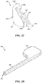
As provided above, the present technology is directed to adjustable flow glaucoma shunts. FIGS. 2A-2E illustrate an adjustable flow shunt 200 (“shunt 200”) configured in accordance with select embodiments of the present technology. Referring first to FIGS. 2A and 2B, which are isometric and top views, respectively, of the shunt 200, the shunt 200 includes a frame 210 (which can also be referred to as a “body element,” “drainage element,” or “shunting element”) having an elongated portion 212 and a bladder portion 214. The bladder portion 214 can define an interior chamber 216 for housing various components of the shunt 200, described below. A lumen 206 can extend through the elongated portion 212 and be fluidly coupled to the interior chamber 216 of the bladder portion 214. The lumen 206 can have a circular, oval, rectangular, or other cross-sectional shape. In some embodiments, for example, the lumen 206 has a rectangular cross-section to minimize a dimension (e.g., a height, width, diameter, etc.) of the elongated portion 212. The elongated portion 212 can have a cross-sectional shape matching the lumen 206 (e.g., rectangular). In some embodiments, the elongated portion 212 defines the lumen 206. In other embodiments, a flow tube (not shown) is positioned within the elongated portion 212 to form the lumen 206. Although the frame 210 is illustrated as transparent in FIGS. 2A and 2B so that internal components of the shunt 200 can be depicted, the frame 210 need not be transparent and can substantially encase portions of the shunt, as described in greater detail with respect to FIGS. 2D and 2E.
In some embodiments, at least a portion of the elongated portion 212 is configured for placement within an anterior chamber of an eye in a region outside of the optical field of view of the eye, and the bladder portion 214 is configured for placement within a desired outflow location, such as a subconjunctival bleb space. In such embodiments, aqueous can flow from the anterior chamber and into the lumen 206 via a first (e.g., inflow) port 207. The aqueous can then flow through the lumen 206 and into the interior chamber 216. Once in the interior chamber 216, the aqueous may drain into the desired outflow location via a second (e.g., outflow) port 208. In other embodiments, the orientation of the shunt 200 can be reversed when implanted, such that the bladder portion 214 is positioned in the anterior chamber and the first port 207 of the elongated portion 212 is positioned in the desired outflow location. In such embodiments, aqueous flows in the opposite direction as described above: aqueous enters the shunt 200 at the interior chamber 216 via the second port 208, flows through the lumen 206, and drains into the desired outflow location via the first port 207.
In some embodiments, the shunt 200 has a generally flat profile (e.g., as defined by the frame 210). For example, the frame 210 (the elongated portion 212, the bladder portion 214, or both the elongated portion 212 and the bladder portion 214) can have a longitudinal cross-sectional dimension (e.g., height, width, diameter, etc.) of about 100 μm or less, 90 μm or less, 80 μm or less, 70 μm or less, 60 μm or less, and/or 50 μm or less. In some embodiments, use of a rectangular or oval-shaped lumen 206 (as opposed to a circular lumen) may help decrease one or more dimensions of the shunt 200 without substantially affecting the therapy provided by the shunt 200. Without being bound by theory, reducing the one or more dimensions of the shunt 200 may help reduce and/or minimize damage to the eye during and after implanting the shunt 200 into the eye, which in turn may reduce the recovery time following the implant procedure and/or reduce side effects associated with the shunt. The overall shape “L” shape of the shunt 200 may also help anchor the shunt in position and prevent unwanted migration of the shunt 200 despite its relatively small profile.
The shunt 200 further includes a flow control assembly 220 (also referred to herein as an “actuation assembly”) positioned in the interior chamber 216. The flow control assembly 220 can include an anchor 221, one or more actuation elements 222, and a lever or gating element 225. As will be described in greater detail below with reference to FIG. 2C, the flow control assembly 220 is configured to control the flow of fluid through the lumen 206 by selectively blocking and/or unblocking a portion of the lumen 206 that is in fluid communication with the interior chamber 216.
FIG. 2C is an enlarged view of the flow control assembly 220 depicted alone with other features of the shunt 200 (FIGS. 2A and 2B) omitted for purposes of illustration. As noted above, the flow control assembly 220 includes an anchor 221, actuation elements 222 (shown as a first actuation element 222 a and a second actuation element 222 b, and collectively referred to as the “actuation elements 222”), and a gating element 225. The anchor 221 is configured to secure the flow control assembly 220 in a desired position within the interior chamber 216. For example, the anchor 221 can conform to a portion of the interior chamber 216. In other embodiments, the anchor 221 can otherwise secure the flow control assembly 220 to the frame 210. The anchor 221 can also provide an anchoring element for the actuation elements 222. For example, the anchor 221 can include a first anchoring element 223 a and a second anchoring element 223 b extending from a body portion 223 c of the anchor 221. The anchoring elements 223 a and 223 b can be integral with the body portion 223 c or can be separate components otherwise secured to the body portion 223 c. The anchoring elements 223 a-223 c remain generally static during operation of the actuation elements 222, described below.
The gating element 225 includes a first portion 227 (e.g., an “arm”) positioned between the first actuation element 222 a and the second actuation element 222 b and a second portion 226 spaced apart from the first portion 225. The second portion 226 can be configured to at least partially block the lumen 206 and/or an aperture or orifice of the lumen 206 (thus at least partially blocking fluid from flowing out of the lumen 206 and into the interior chamber 216) in certain configurations, such as the configuration depicted in FIGS. 2A and 2B. Accordingly, the second portion 226 can also be referred to as a “blocking feature” or a “flow control element.” The gating element 225 can have a generally elbow or “L” shape, although other configurations are possible.
The first actuation element 222 a extends between the first anchoring element 223 a and the first portion 227 of the gating element 225. The second actuation element 222 b extends between the second anchoring element 223 b and the first portion 227 of the gating element 225. The actuation elements 222 are configured to move the gating element 225 between a plurality of positions to control the flow of fluid through the shunt 200. For example, the first actuation element 222 a and the second actuation element 222 b can be composed of a shape memory material, such as a shape memory alloy (e.g., nitinol). Accordingly, the first actuation element 222 a and the second actuation element 222 b can be transitionable at least between a first material phase or state (e.g., a martensitic state, a R-phase, a composite state between martensitic and R-phase, etc.) and a second material phase or state (e.g., an austenitic state, an R-phase state, a composite state between austenitic and R-phase, etc.). In the first material state, the first actuation element 222 a and the second actuation element 222 b may be deformable (e.g., plastic, malleable, compressible, expandable, etc.). In the second material state, the first actuation element 222 a and the second actuation element 222 b may have a preference toward a specific preferred geometry (e.g., original geometry, manufactured geometry, heat set geometry, etc.). The first actuation element 222 a and the second actuation element 222 b can be transitioned between the first material state and the second material state by applying energy (e.g., heat) to the actuation elements to heat the actuation elements above a transition temperature. Energy can be applied to the actuation elements via an energy source positioned external to the body (e.g., a laser), RF heating, resistive heating, or the like. In some embodiments, the transition temperature for both the first actuation element 222 a and the second actuation element 222 b is above an average body temperature (e.g., an average temperature in the eye). Accordingly, both the first actuation element 222 a and the second actuation element 222 b are generally in the deformable first state when the shunt 200 is implanted in the body until they are actuated. If an actuation element (e.g., the first actuation element 222 a) is deformed relative to its preferred geometry while in the first state, heating the actuation element (e.g., the first actuation element 222 a) above its transition temperature causes the actuation element to transition to the second state and therefore move from the deformed shape to and/or toward its preferred geometry. In some embodiments, the first actuation element 222 a can be selectively heated independently of the second actuation element 222 b, and the second actuation element 222 b can be selectively heated independently of the first actuation element 222 a.
The first actuation element 222 a and the second actuation element 222 b generally act in opposition. For example, if the second actuation element 222 b is deformed relative to its preferred geometry, actuation of the second actuation element 222 b (e.g., heating the second actuation element 222 b above its transition temperature) causes the second actuation element 222 b to move toward its preferred geometry. This causes a corresponding deformation in the first actuation element 222 a, which remains in the first material state and thus is generally malleable. For example, in the illustrated embodiment, the second actuation element 222 b is compressed (e.g., shortened) relative to its preferred geometry. Heating the second actuation element 222 b above its transition temperature causes the second actuation element 222 b to straighten out (e.g., lengthen, expend, etc.) and move toward its preferred geometry. Because the second anchoring element 223 b does not move as the second actuation element 222 b changes shape, the first actuation element 222 a (which is not heated and therefore in the first generally malleable state) is compressed to account for the shape change of the second actuation element 222 b. This also moves the first portion 227 of the gating element 225 toward the first anchoring element 223 a, which causes the second portion 226 of the gating element 225 to unblock and/or further unblock the lumen 206. This can increase flow through the lumen 206. The operation can be reversed by heating the first actuation element 222 a above its transition temperature, which causes it to move (e.g., expand) toward its preferred geometry, which moves the first portion 227 of the gating element 225 back toward the second anchoring element 223 b and the second portion 226 of the gating element 225 back into a blocking position. This can decrease flow through the lumen 206. Accordingly, the first actuation element 222 a and the second actuation element 222 b can be selectively and independently actuated to further block or unblock the lumen 206 to change the flow of fluid therethrough. In some embodiments, the gating element 225 can be moved to any number of positions between fully blocking and fully unblocking the lumen 206, and the flow control assembly 220 can be selectively adjusted after placement within the eye (e.g., via non-invasive energy) to provide a variety of different outflow resistance levels by incrementally adjusting the gating element 225 relative to the lumen 206. Additional details regarding the operation of flow control mechanisms generally similar to the flow control mechanism 220 are described below in Section D and with reference to FIGS. 5A-5D.
FIGS. 2D and 2E illustrate a cover 240 encasing the shunt 200. In some embodiments, the cover 240 is a thin protective membrane surrounding the frame 210. In other embodiments, the cover 240 is simply the outer surface of the frame 210. In embodiments in which the cover 240 is separate from the frame 210, the cover 240 includes an elongated portion 242 corresponding to the elongated portion 212 of the frame 210. The cover 240 also includes a bladder portion 244 corresponding to the bladder portion 214 of the frame 210. Referring to FIG. 2D, a first end portion (e.g., the proximal end portion) of the cover 240 has an opening 241 that aligns with the first port 207 to provide fluid access to lumen 206. As illustrated, the opening 241 can be rectangular to match the cross-section of the lumen 206. Referring to FIG. 2E, a second end portion (e.g., a distal end portion) of the cover 240 has an opening 245 that aligns with the second port 208 to permit fluid to flow out of the shunt 200. In embodiments in which the bladder portion 244 is positioned in the desired outflow location (e.g., the bleb space), the opening 245 directs fluid away from the globe of the eye and ensures that any growth in the bleb due to the outflow of fluid occurs in a direction away from the globe of the eye.
FIGS. 3A-3D illustrate an adjustable flow shunt 300 (“shunt 300”) configured in accordance with select embodiments of the present technology. In particular, FIG. 3A is an isometric view of the shunt 300, FIG. 3B is a top view of the shunt 300, FIG. 3C is an enlarged view of a flow control assembly 320 of the shunt 300, and FIG. 3D is an isometric view of a frame 310 of the shunt 300. The shunt 300 can be similar to the shunt 200. For example, referring to FIGS. 3A and 3B, the shunt 300 includes a frame 310 having an elongated portion 312 and a bladder portion 314. The bladder portion 314 defines an interior chamber 316. A lumen 306 extends through the elongated portion 312 and is fluidly coupled to the interior chamber 316. The shunt 300 further includes a flow control assembly 320 having an anchor 321, actuation elements 322, and a gating element 325. Referring to FIG. 3C, the anchor 321 can include a first anchor element 323 a, a second anchor element 323 b, and a base portion 323 c. The gating element 325 can include a first portion 327 and a second portion 326. The actuation elements 322 can include a first actuation element 322 a extending between the first anchor element 323 a and the first portion 327 of the gating element 325, and a second actuation element 322 b extending between the second anchor element 232 b and the first portion 327 of the gating element 325. The shunt 300, including the flow control assembly 320, can operate in a similar fashion as the shunt 200 described above with respect to FIGS. 2A-2D. The following description of the shunt 300 therefore focuses on features of the shunt 300 that are different than the shunt 200. However, one skilled in the art will appreciate that the description of like features for the shunt 200 apply to like features of the shunt 300.
Referring now to FIG. 3B, the frame 310 can be angled. For example, the longitudinal axis A of the elongated portion 312 can be non-parallel to the longitudinal axis B of the bladder portion. For example, the longitudinal axis A and the longitudinal axis B may form an angle θ between about 90 degrees and about 180 degrees, such as about 95 degrees, about 100 degrees, about 105 degrees, about 110 degrees, about 115 degrees, about 120 degrees, about 125 degrees, about 130 degrees, about 135 degrees, about 140 degrees, about 145 degrees, about 150 degrees, about 155 degrees, about 160 degrees, about 165 degrees, about 170 degrees, or about 175 degrees. In some embodiments, the angled or non-linear configuration of the frame 310 is expected to help secure the shunt 300 in a desired position. For example, the bend formed by the bladder portion 314 and the elongated portion 312 can act as a wedge to help prevent and/or reduce axial or lateral migration of the shunt 300.
Referring next to FIG. 3D, which illustrates the frame 310 with the flow control assembly 320 (FIGS. 2C) omitted for purposes of illustration, the frame 310 can also include a plurality of apertures 345 configured to fluidly connect the interior chamber 316 an environment external to the bladder portion 314. For example, when implanted within the eye, the bladder portion 314 can be positioned within a target outflow location, and the apertures 345 permit aqueous draining through the shunt 300 to exit the interior chamber 316 and flow into the bleb space. In some embodiments, the plurality of apertures 345 are positioned only on a medial and/or distal portion of the bladder portion 314 (relative to the elongated portion 312), with no apertures positioned on the proximal portion of the bladder portion 314 that is adjacent to the elongated portion 312. Such configuration directs aqueous draining through the apertures 345 away from the globe of eye and ensures any growth in the drainage bleb will also be away from the globe of the eye. Further, having a plurality of apertures 345 enables drainage of aqueous to continue even if one of the apertures 345 becomes blocked by tissue ingrowth or clotting. The plurality of apertures 345 can be in addition to or in lieu of a primary outflow drainage port. As described above with respect to FIGS. 2C and 2D, the shunt 300 can further include a cover and/or the frame's outer surface can comprise a material suitable for exposure to tissue. If the shunt 300 has a cover, the cover can include a plurality of holes configured to align with the plurality of apertures 345.
As one skilled in the art will appreciate, adjustable shunts configured in accordance with the present technology can include any combination of the above described features and are not limited to the specific embodiments illustrated herein. For example, while the elongated portion is depicted as intersecting with the bladder portion at a proximal corner of the bladder portion, the elongated portion can alternatively intersect the bladder portion at a central or other region of the bladder portion. Likewise, various components of the flow control assemblies described herein, such as the anchor, the actuation elements, and the gating element, can take any number of configurations without deviating from the scope of the present technology.
Although the shunts discussed above are primarily described as having the flow control assembly positioned at or adjacent an outflow end of the shunt, the flow control assemblies described herein can also be positioned at other positions along the length of the shunt. For example, the flow control assembly can be positioned near a proximate (e.g., inflow) end of the shunt and/or within an anterior chamber. Accordingly, the shunts described above in FIGS. 2A-3D can be oriented in multiple directions, depending on the desired arrangement (e.g., the shunts can be implanted with the flow control assembly proximate the anterior chamber or with the flow control assembly proximate the desired outflow location). In some embodiments, placing the flow control assembly in the anterior chamber is expected to reduce the amount of tissue interference with the non-invasive energy used to selectively adjust the flow control assembly. In embodiments in which the flow control assembly is positioned within the anterior chamber, the bladder portion of the outer membrane can also be positioned within the anterior chamber. When placed in the anterior chamber, the bladder portion can serve several similar functions to those described above. For example, the bladder portion can protect the flow control assembly and/or anchor the shunt. If the bladder portion is positioned around the flow control assembly in the anterior chamber, the shunts described herein can optionally have a second bladder surrounding the outflow end of the shunt. The second bladder can reduce backflow pressure through the shunt and/or help prevent tissue ingrowth in a bleb or other desired outflow location.
C. Methods of Manufacturing Flow Control Assemblies with Shape Memory Actuation Elements
Aspects of the present technology are further directed to methods of manufacturing the devices described herein. As described herein, select embodiments of the present technology include a flow control assembly (e.g., the flow control assemblies 220 and 320 of the shunts 200 and 300, respectively) composed, at least in part, of a shape memory material such as nitinol. To manufacture such nitinol-based flow control assemblies, the desired shape of the flow control assembly can be fabricated (e.g., cut, such as laser cut) from a piece (e.g., sheet, strip, etc.) of nitinol. In some embodiments, the flow control assembly can be fabricated from a single piece of nitinol.
FIGS. 4A and 4B illustrate various stages of manufacture of a flow control assembly 420 (which can also be referred to herein as an “actuation assembly”) fabricated from a piece (e.g., a sheet or strip) of nitinol or other suitable material in accordance with select embodiments of the present technology. More specifically, FIG. 4A illustrates a structure corresponding to the flow control assembly 420 after it has been cut from a sheet of nitinol (e.g., the “fabricated” or “cut” “configuration”), and FIG. 4B illustrates the flow control assembly 420 after it has been manipulated into an operational position (e.g., the “assembled” or “operational” configuration). As described below, in at least some embodiments the flow control assembly is fabricated as a unitary structure from a single piece of material. The flow control assembly 420 can include features generally similar to the features described above with respect to the flow control assemblies 220 and 320. For example, the flow control assembly 420 can include an anchor 421 having anchoring elements 423 a and 423 b. The flow control assembly 420 can also include actuation elements 422 a and 422 b and a gating element 425. As described above, the gating element 425 can include a first portion 427 and a second portion 426. In the illustrated embodiment, the flow control assembly 420 further includes a notch 428 in the first anchoring element 423 a.
Referring to FIG. 4A, the illustrated embodiment shows the fabricated configuration of the flow control assembly before it has been formed into its operational configuration. As described above with respect to FIGS. 2C and 3C, the first actuation element 422 a has a first end portion connected to the arm 427 and a second end portion spaced apart from the arm 427. In the fabricated configuration, the second end portion of the first actuation element 422 a is free (i.e., the second end portion is not secured to the anchor 421 and/or the first anchoring element 423 a) and both the first actuation element 422 a and the second actuation element 422 b are in their preferred geometry (e.g., their original, manufactured geometry). In some embodiments, the first actuation element 422 a and the second actuation element 422 b can have the same preferred geometry. In other embodiments, the first actuation element 422 a and the second actuation element 422 b can have different preferred geometries.
The fabricated configuration can be converted into the operational configuration by securing the second end portion of the first actuation element 422 a (i.e., the free end) to the anchor 421 and/or the first anchoring element 423 a. The process of securing the free end of the first actuation element 422 a to the first anchoring element 423 a deforms the first actuation element 422 a and/or the second actuation element 422 b relative to its preferred geometry (thereby “prestraining” and/or “prestressing” the first actuation element 422 a and/or the second actuation element 422 b). For example, in the embodiment illustrated in FIG. 4B, the first actuation element 422 a and the second actuation element 422 b can be bent or otherwise compressed such that the second end portion of the first actuation element 422 a is positioned within the notch 428 of the first anchoring element 423 a, thereby securing the flow control assembly 420 in the operational configuration. The first actuation element 422 a and/or the second actuation element 422 b are therefore at least partially bent, compressed, or otherwise deformed relative to their preferred geometry (shown in FIG. 4A) as they are placed into the operational configuration. In the operational configuration, the first actuation element 422 a may exert a generally outward and/or upward force on the first anchoring element 423 a to ensure that the first actuation element 422 a remains in the notch 428 and that the flow control assembly 420 remains in the operational configuration. In some embodiments, the first actuation element 422 a can be secured to the first anchoring element 423 a by other means in addition to, or in lieu of, the outward and/or upward force generated by the first actuation element 422 a. For example, the first actuation element 422 a can be welded, bonded, or otherwise secured to the first anchoring element 423 a.
In some embodiments, the first actuation element 422 a and/or the second actuation element 422 b are stretched or otherwise lengthened when placing the flow control assembly 420 in the operational configuration. For example, in some embodiments the first anchoring element 423 a may be spaced apart from the second anchoring element 423 b by a length greater than a combined length of the first actuation element 422 a and the second actuation element 422 b in the fabricated configuration. Accordingly, to transform the flow control assembly 420 into the operational configuration, the first actuation element 422 a and/or the second actuation element 422 b can be stretched or lengthened relative to their preferred geometries. Once stretched, the first actuation element 422 a can be secured to the first anchoring element 423 a (e.g., via welding, bonding, or other suitable techniques) to hold the flow control assembly 420 in the operational configuration.
Once in the operational configuration, the flow control element 420 can be positioned within a shunt (e.g., inserted into an interior chamber, such as the interior chamber 216 or 316 described above respect to the shunts 200 and 300, respectively). In some embodiments, the geometry/topography of the anchor 421 conforms with a portion of the interior chamber such that the flow control assembly 421 is automatically anchored in position when positioned in the interior chamber. Alternatively or additionally, the flow control assembly 420 can be secured to the shunt using other anchoring techniques that do not substantially interfere with operation of the shunt. Once positioned within the shunt, the flow control assembly 420 can operate as described in Section D below with respect to FIGS. 5A-5D.
In some embodiments, the first actuation element 422 a and/or the second actuation element 422 b are optionally biased after placing the flow control assembly in the operational configuration. For example, the first actuation element 422 a can be manipulated (e.g., using energy) such that is has a different length than the second actuation element 422 b. In such embodiments, the first actuation element 422 a is configured to retain its biased shape (e.g., the first actuation element 422 a can be composed of a shape-memory material such as nitinol). Biasing at least one of the actuation elements before deployment of the shunt places the shunt in an “open” (e.g., permitting flow), partially “open”, or “closed” (e.g., not permitting flow) position for the implant procedure. The biasing step can be done before or after placement of the flow control assembly 420 within the shunt.
Without being bound by theory, the above method of manufacturing the flow control assemblies described herein provides several advantages. For example, it enables the flow control assembly to be fabricated (e.g., cut) as a unitary structure from a single piece of material, which is expected to simplify the manufacturing process. As another example, because it is formed from a unitary structure, the flow control assemblies may have fewer coupled parts that could malfunction after being implanted into the patient, which may in at least some cases increase the life of the shunts described herein. However, as one skilled in the art will appreciate from the disclosure herein, the flow control assemblies described herein can be formed by methods other than those described above with respect to FIGS. 4A and 4B. For example, in embodiments wherein the flow control assemblies comprise nitinol, the flow control assemblies can be formed using any technique suitable for manipulating nitinol into the desired configuration. Accordingly, the present technology is not limited to the methods of manufacture expressly described herein. Rather, the shunts described herein can be manufactured using other suitable methods not expressly set forth herein.
D. Operation of Shape Memory Actuation Elements
As described above, the present technology is generally directed to implantable systems and devices for facilitating the flow of fluid between a first body region and a second body region. The devices generally include a drainage and/or shunting element having a lumen extending therethrough for draining or otherwise shunting fluid between the first and second body regions. Further, devices configured in accordance with the present technology may be selectively adjustable to control the amount of fluid flowing between the first and second body regions. In some embodiments, for example, the devices comprise a flow control assembly or actuation assembly that drives movement of a gating element to modulate flow resistance through the lumen, thereby increasing or decreasing the relative drainage rate of fluid between the first body region and the second body region.
In some embodiments of the present technology, the flow control assemblies (e.g., actuation assemblies, fluid resistors, etc.) comprise at least two actuation elements coupled to a moveable element (e.g., a gating element, an arm, etc.). The moveable element can be formed to interface with (e.g., at least partially block) a lumen and/or a lumen orifice. The orifice can be an inflow orifice or an outflow orifice. In other embodiments, the moveable element can be an intermediate element between the actuation element and a flow control element that interfaces with or otherwise engages a shunt lumen or orifice. In such embodiments, movement of the moveable element can adjust a geometry of the flow control element, which in turn adjusts a size, shape, or other dimension of a shunt lumen or orifice. Movement of the actuation elements generates (e.g., translational and/or rotational) movement of the moveable element.
The actuation element(s) can include a shape memory material (e.g., a shape memory alloy, or a shape memory polymer), and movement of the actuation element(s) can be generated through applied stress and/or use of a shape memory effect (e.g., as driven by a change in temperature). The shape memory effect enables deformations that have altered an element from its preferred geometric configuration (e.g., original configuration, shape-set configuration, heat-set configuration, etc.) to be largely or entirely reversed during operation of the flow control assembly. For example, thermal actuation (heating) can reverse deformation(s) by inducing a change in state (e.g., phase change) in the actuator material, inducing a temporary elevated internal stress that promotes a shape change toward the preferred geometric configuration. For a shape memory alloy, the change in state can be from a martensitic phase (alternatively, R-phase) to an austenitic phase. For a shape memory polymer, the change in state can be via a glass transition temperature or a melting temperature. The change in state can reverse deformation(s) of the material—for example, deformation with respect to its preferred geometric configuration—without any (e.g., externally) applied stress to the actuation element. That is, a deformation that is present in the material at a first temperature (e.g., body temperature) can be (e.g., thermally) recovered and/or altered by raising the material to a second (e.g., higher) temperature. Upon cooling (and changing state, e.g., back to martensitic phase), the actuation element retains its preferred geometric configuration. With the material in this relatively cooler-temperature condition it may require a lower force or stress to thermoelastically deform the material, and any subsequently applied external stress can cause the actuation element to once again deform away from the preferred geometric configuration.
The actuation element(s) can be processed such that a transition temperature at which the change in state occurs (e.g., the austenite start temperature, the austenite final temperature, etc.) is above a threshold temperature (e.g., body temperature). For example, the transition temperature can be set to be about 45 deg. C., about 50 deg. C., about 55 deg. C., or about 60 deg. C. In some embodiments, the actuator material is heated from body temperature to a temperature above the austenite start temperature (or alternatively above the R-phase start temperature) such that an upper plateau stress (e.g., “UPS_body temperature”) of the material in a first state (e.g., thermoelastic martensitic phase, or thermoelastic R-phase at body temperature) is lower than an upper plateau stress (e.g., “UPS_actuated temperature”) of the material in a heated state (e.g., superelastic state), which achieves partial or full free recovery. For example, the actuator material can be heated such that UPS_actuated temperature>UPS_body temperature. In some embodiments, the actuator material is heated from body temperature to a temperature above the austenite start temperature (or alternatively above the R-phase start temperature) such that an upper plateau stress of the material in a first state (e.g., “thermoelastic martensite or thermoelastic R-phase at body temperature”) is lower than a lower plateau stress (e.g., “LPS”) of the material in a heated state (e.g., superelastic state), which achieves partial or full free recovery. For example, the actuator material can be aged such that LPS_activated temperature>UPS_body temperature. In some embodiments, the actuator material is heated from body temperature to a temperature above the austenite start temperature (or alternatively above the R-phase start temperature) such that an upper plateau stress of the material in a first state (e.g., thermoelastic martensite or thermoelastic R-phase) is higher than a lower plateau stress of the material in a heated state, which achieves partial free recovery. For example, the actuator material can be aged such that LPS_activated temperature<UPS_body temperature.
The flow control assembly can be formed such that the actuation elements have substantially the same preferred geometric configuration (e.g., memory shape, or length, L0). The flow control assembly can be assembled such that, upon introduction into a patient (e.g., implantation), at least one (e.g., a first) actuation element/shape memory element has been deformed with respect to its preferred geometric configuration (e.g., to have L1≠L0), while at least one other opposing (e.g., a second) actuation element/shape memory element positioned adjacent to the first actuation element is substantially at its preferred geometric configuration (e.g., L0). In other embodiments, however, both the first and second actuation elements may be deformed with respect to their corresponding preferred geometric configurations upon introduction into the patient (e.g., the first actuation element is contracted relative to its preferred geometric configuration and the second actuation element is expanded relative to its preferred geometric configuration).
In some embodiments of the present technology, L1>L0—for example, the deformed first actuation element is elongated with respect to its preferred “shape memory: length. In some embodiments, L1<L0—for example, the deformed first actuation element is compressed with respect to its preferred shape memory length. The flow control assembly can be formed such that, in operation, its overall dimension (e.g., overall length) is substantially fixed (e.g., L0+L1=a constant). For example, (e.g., outermost) ends of the actuation elements can be fixed, such that movement of the actuation elements occurs between the points of fixation. The overall geometry of the actuation elements, along with the lengths, can be selected such that, in operation, deformation within the actuation elements remains below about 10%, about 9%, about 8%, about 7%, or about 6%.
The (e.g., first and second) actuation elements are arranged such that a movement (e.g., deflection or deformation) of the first actuation element/first shape memory element is accompanied by (e.g., causes) an opposing movement of the second actuation element/second shape memory element. The movement can be a deflection or a deformation. In operation, selective heating of the first actuation element of the flow control assembly causes it to move to and/or toward its preferred geometric configuration (e.g., revert from L1 to L0), moving the coupled moveable element. At the same time, the elongation of the first actuation element is accompanied by (e.g., causes) a compression of the second actuation element (e.g., from L0 to L1). The second actuation element is not heated (e.g., remains at body temperature), and therefore the second actuation element deforms (e.g., remains martensitic and compresses). The first actuation element cools following heating, and returns to a state in which it can be plastically deformed. To reverse the configuration of the flow control assembly (e.g., the position of the moveable element), the second actuation element is heated to move to and/or toward its preferred geometric configuration (e.g., from L1 to L0). The return of the second actuation element to its preferred geometric configuration causes the moveable element to move back to its prior position, and compresses the first actuation element (e.g., from L0 to L1). The position of the moveable element for the flow control assembly can be repeatably toggled (e.g., between open and closed) by repeating the foregoing operations. The heating of an actuation element can be accomplished via application of incident energy (e.g., via a laser or inductive coupling). Further, as mentioned above, the source of the incident energy may be external to the patient (e.g., non-invasive).
FIGS. 5A-5D schematically illustrate operation of a flow control assembly 500 for use with an adjustable flow shunt and configured in accordance with select embodiments of the present technology. Although the flow control assembly 500 is shown schematically, one skilled in the art will appreciate that the principles and modes of operation discussed with respect to the flow control assembly 500 can apply to any of the flow control assemblies disclosed herein. Accordingly, the flow control assembly 500 can be generally similar to and/or the same as the flow control assemblies 220, 320, and 420 previously described.
Referring collectively to FIGS. 5A-5D, the flow control assembly 500 can include a first actuation element 501 and a second actuation element 502, which can be generally similar to the actuation elements described previously with respect to FIGS. 2A-4B. The first actuation element 501 can extend between the gating element 503 and a first anchoring element 504. The second actuation element 502 can extend between the gating element 503 and a second anchoring element 505. The first anchoring element 504 and the second anchoring element 505 can be secured to a generally static component of the shunt (not shown). In other embodiments, the first anchoring element 504 and/or the second anchoring element 505 can be omitted and the first actuation element 501 and/or the second actuation element 502 can be secured directly to a portion of the device or system for shunting fluid (not shown). In any of these embodiments, selectively modifying fluid flow through the shunt by moving the gating element 503 occurs without damaging or otherwise negatively affecting tissue of the patient.
The first actuation element 501 and the second actuation element 502 can be composed of a shape memory material, such as a shape memory alloy (e.g., nitinol). Accordingly, the first actuation element 501 and the second actuation element 502 can be transitionable between a first material phase or state (e.g., a martensitic material state, an R-phase material state, etc.) and a second material phase or state (e.g., an austenitic material state, an R-phase material state, etc.). In the first state, the first actuation element 501 and the second actuation element 502 may be deformable (e.g., plastic, malleable, compressible, expandable, etc.). In the second state, the first actuation element 501 and the second actuation element 502 may have a preference toward a specific preferred geometry (e.g., original geometry, manufactured geometry, heat set geometry, etc.). The first actuation element 501 and the second actuation element 502 can be transitioned between the first state and the second state by applying energy (e.g., heat) to the actuation elements to heat the actuation elements above a transition temperature. In some embodiments, the transition temperature for both the first actuation element 501 and the second actuation element 502 is above an average body temperature (e.g., an average temperature in the eye). Accordingly, both the first actuation element 501 and the second actuation element 502 are typically in the deformable first state when the flow control assembly 500 is implanted in the body until they are heated (e.g., actuated).
If an actuation element (e.g., the first actuation element 501) is deformed relative to its preferred geometry while in the first state, heating the actuation element (e.g., the first actuation element 501) above its transition temperature causes the actuation element to transition to the second state and therefore transition from the deformed shape to and/or toward its preferred geometry. Heat can be applied to the actuation elements via an energy source positioned external to the body (e.g., a laser), RF heating, resistive heating, or the like. In some embodiments, the first actuation element 501 can be selectively heated independently of the second actuation element 502, and the second actuation element 502 can be selectively heated independently of the first actuation element 501.
Referring to FIG. 5A, the first actuation element 501 and the second actuation element 502 are shown in a state before being secured to the first and second anchoring elements. In particular, the first actuation element 501 and the second actuation element 502 are in their unbiased preferred geometries. In the illustrated embodiment, the first actuation element 501 has an original shape having a length Lx1, and the second actuation element 502 has an original shape having a length Ly1. In some embodiments, Lx1 is equal to Ly1. In other embodiments, Lx1 is less than or greater than (i.e., not equal to) Ly1.
FIG. 5B illustrates the flow control assembly 500 in a first (e.g., assembled or operational) configuration after the first actuation element 501 has been secured to the first anchoring element 504, and the second actuation element 502 has been secured to the second anchoring element 505. In the first configuration, both the first actuation element 501 and the second actuation element 502 are at least partially deformed (e.g., prestressed and/or prestrained) relative to their preferred geometries. For example, the first actuation element 501 is compressed (e.g., shortened) relative to its preferred geometry (FIG. 5A) such that it assumes a second length Lx2 that is less than the first length Lx1. Likewise, the second actuation element 502 is also compressed (e.g., shortened) relative to its preferred geometry (FIG. 5A) such that it assumes a second length Ly2 that is less than the first length Ly1. In the illustrated embodiment, Lx1 is equal to Ly1, although in other embodiments Lx1 can be less than or greater than (i.e., not equal to) Ly1. In other embodiments, the first actuation element 501 and/or the second actuation element 502 are stretched (e.g., lengthened) relative to their preferred geometries before being secured to the anchoring elements. For example, in some embodiments both the first actuation element 501 and the second actuation element 502 are stretched relative to their preferred geometries. In other embodiments, the first actuation element 501 is compressed (e.g., shortened) relative to its preferred geometry and the second actuation element 502 is stretched (e.g., lengthened) relative to its preferred geometry. In some embodiments, only one of the actuation elements (e.g., the first actuation element 501) is deformed relative to its preferred geometry, and the other actuation element (e.g., the second actuation element 502) retains its preferred geometry.
FIG. 5C illustrates the flow control assembly 500 in a second configuration different than the first configuration. In particular, in the second configuration, the flow control assembly 500 has been actuated relative to the first configuration shown in FIG. 5B to transition the first actuation element 501 from the first (e.g., martensitic) state to the second (e.g., austenitic) state. Because the first actuation element 501 was deformed (e.g., compressed) relative to its preferred geometry while in the first configuration, heating the first actuation element 501 above its transition temperature causes the first actuation element 501 to move to and/or toward its preferred geometry having a length Lx1 (FIG. 5A). As described above, the first anchoring element 504 and the second anchoring element 505 are fixedly secured to a generally static structure (e.g., such that a distance between the first anchoring element 504 and the second anchoring element 505 does not change during actuation of the first actuation element 501). Accordingly, as the first actuation element 501 increases in length toward its preferred geometry, the second actuation element 502, which is unheated and therefore remains in the generally deformable (e.g., martensitic) state, is further compressed to a length Ly3 that is less than Ly1 and Ly2. In the illustrated embodiment, this moves the gating element 503 away from the first anchoring element 504 and toward the second anchoring element 505.
FIG. 5D illustrates the flow control assembly 500 in a third configuration different than the first configuration and the second configuration. In particular, in the third configuration the flow control assembly 500 has been actuated relative to the second configuration shown in FIG. 5C to transition the second actuation element 502 from the first (e.g., martensitic) state to the second (e.g., austenitic) state. Because the second actuation element 502 was deformed (e.g., compressed) relative to its original shape while in the second configuration, heating the second actuation element 502 above its transition temperature causes the second actuation element 502 to move to and/or toward its preferred geometry having a length Ly1 (FIG. 5A). As described above, the first anchoring element 504 and the second anchoring element 505 are fixedly secured to a generally static structure (e.g., such that the distance between the first anchoring element 504 and the second anchoring element 505 does not change during actuation of the second actuation element 502). Accordingly, as the second actuation element 502 increases in length toward its preferred geometry, the first actuation element 501, which is unheated and therefore remains in the generally deformable (e.g., martensitic) state, is further deformed (e.g., compressed) relative to its original shape to a length Lx3 that is less than Lx1 and Lx2. In the illustrated embodiment, this moves the gating element 503 away from the second anchoring element 505 and toward the first anchoring element 504 (e.g., generally opposite the direction the gating element 503 moves when the first actuation element 501 is actuated).
The flow control assembly 500 can be repeatedly transitioned between the second configuration and the third configuration. For example, the flow control assembly 500 can be returned to the second configuration from the third configuration by heating the first actuation element 501 above its transition temperature once the second actuation element 502 has returned to the deformable first state (e.g., by allowing the second actuation element 502 to cool below the transition temperature). Heating the first actuation element 501 above its transition temperature causes the first actuation element 501 to move to and/or toward its preferred geometry, which in turn pushes the gating element 503 back toward the second anchoring element 505 and transitions the flow control assembly 500 to the second configuration (FIG. 5C). Accordingly, the flow control assembly 500 can be selectively transitioned between a variety of configurations by selectively actuating either the first actuation element 501 or the second actuation element 502. After actuation, the flow control assembly 500 can be configured to substantially retain the given configuration until further actuation of the opposing actuation element. In some embodiments, the flow control assembly 500 can be transitioned to intermediate configurations between the second configuration and the third configuration (e.g., the first configuration) by heating a portion of the first actuation element 501 or the second actuation element 502.
As provided above, heat can be applied to the actuation elements via an energy source positioned external to the body (e.g., a laser), RF heating, resistive heating, or the like. In some embodiments, an external device (e.g., external device 220) directs the energy source to heat the one or more of the actuation elements based on readings from one or more sensors (e.g., sensor 210). In other embodiments, a user (e.g., a physician) operates the energy source to heat one or more of the actuation elements based on readings from one or more sensors. In some embodiments, the first actuation element 501 can be selectively heated independently of the second actuation element 502, and the second actuation element 502 can be selectively heated independently of the first actuation element 501. For example, in some embodiments, the first actuation element 501 is on a first electrical circuit and/or responds to a first frequency range for selectively and resistively heating the first actuation element 501 and the second actuation element 502 is on a second electrical circuit and/or responds to a second frequency range for selectively and resistively heating the second actuation element 502. As described in detail above, selectively heating the first actuation element 501 moves the gating element 503 in a first direction and selectively heating the second actuation element 502 moves the gating element 503 in a second direction generally opposite the first direction. The flow control assembly 500 can therefore be adjusted to achieve any of the operations described herein with respect to adjustable shunts.
As one of skill in the art will appreciate from the disclosure herein, various components of the shunting systems and devices described herein can be omitted without deviating from the scope of the present technology. Likewise, additional components not explicitly described above may be added to the systems and devices described herein without deviating from the scope of the present technology. Accordingly, the present technology is not limited to those the configurations expressly identified herein, but rather encompasses variations and alterations of the described embodiments.
E. Examples
Several aspects of the present technology are set forth in the following examples:
1. A method of manufacturing an adjustable flow shunt having a shunt and a flow control assembly, the method comprising:
    • fabricating a structure corresponding to the flow control assembly from a unitary piece of material, wherein the structure includes an anchoring element, an actuation element, and a gating element, and wherein the actuation element has a first end portion extending from the gating element and a second end portion not connected to another portion of the structure;
    • securing the second end portion of the actuation element to the anchoring element to form the flow control assembly; and
    • coupling the assembled flow control assembly to the shunt such that the flow control assembly is configured to at least partially control the flow of fluid through the shunt.
2. The method of example 1 wherein the anchoring element includes a notch, and wherein securing the second end portion of the actuation element to the anchoring element comprises positioning the second end portion of the actuation element into the notch.
3. The method of example 1 wherein securing the second end portion of the actuation element to the anchoring element comprises welding or bonding the second end portion of the actuation element to the anchoring element.
4. The method of any of examples 1-3 wherein securing the second end portion of the actuation element to the anchoring element includes at least partially deforming the actuation element relative to its fabricated geometry.
5. The method of example 4 wherein at least partially deforming the actuation element relative to its fabricated geometry includes prestressing and/or prestraining the actuation element.
6. The method of example 4 or 5 wherein at least partially deforming the actuation element includes compressing the actuation element.
7. The method of example 4 or 5 wherein at least partially deforming the actuation element includes lengthening the actuation element.
8. The method of any of examples 1-7 wherein fabricating the structure corresponding to the flow control assembly from the single piece of material includes laser cutting the structure from the single piece of material.
9. The method of any of examples 1-8 wherein the single piece of material is a sheet of nitinol and/or a strip of nitinol.
10. The method of any of examples 1-9 wherein the actuation element is a first actuation element, and wherein the structure further includes a second actuation element that, after the fabricating step, has a first end portion coupled to the anchoring element and a second end portion coupled to the gating element.
11. The method of example 10 wherein securing the second end portion of the first actuation element to the anchoring element includes at least partially deforming both the first actuation element and the second actuation element relative to their fabricated geometries.
12. The method of any of examples 1-11, further comprising biasing the actuation element before coupling the assembled flow control assembly to the shunt.
13. The method of any of examples 1-12 wherein coupling the assembled flow control assembly to the shunt includes positioning the flow control assembly within a frame.
14. A method of manufacturing a flow control assembly for use with an implantable medical device, the method comprising:
    • cutting a unitary structure corresponding to the flow control assembly from a sheet of nitinol and/or a strip of nitinol, wherein the unitary structure includes an anchoring element, one or more actuation elements, and a gating element, and wherein, once cut from the sheet and/or strip of nitinol, the actuation element has a first geometry; and
    • securing a free end of the actuation element to the anchoring element to form the flow control assembly, wherein securing the free end of the actuation element to the anchoring element deforms the actuation element such that it has a second geometry different than the first geometry.
15. The method of example 14 wherein securing the free end of the actuation element to the anchoring element includes compressing the actuation element.
16. The method of example 14 wherein securing the free end of the actuation element to the anchoring element includes lengthening the actuation element.
17. The method of example 14 wherein the first geometry has a greater length than the second geometry.
18. The method of example 14 wherein the first geometry has a shorter length than the second geometry.
19. The method of any of examples 14-18 wherein the actuation element is a first actuation element, and wherein the unitary structure further includes a second actuation element that, once cut from the sheet and/or strip of nitinol, has a third geometry.
20. The method of example 19 wherein the third geometry is different than the first geometry.
21. The method of example 19 wherein the third geometry is the same as the first geometry.
22. The method of any of examples 19-21 wherein securing the free end of the actuation element to the anchoring element at least partially deforms the second actuation element such that it has a fourth geometry different than the third geometry.
23. The method of example 22 wherein the fourth geometry is different than the second geometry.
24. The method of example 22 wherein the fourth geometry is the same as the second geometry.
23. A method of manufacturing a flow control assembly for use with an implantable medical device, comprising:
    • fabricating a unitary structure corresponding to a flow control assembly, wherein the unitary structure includes an anchoring element, one or more actuation elements, and a gating element, and wherein, once fabricated, the actuation element has a first geometry; and
    • securing a free end of the actuation element to the anchoring element to form the flow control assembly, wherein securing the free end of the actuation element to the anchoring element deforms the actuation element such that it has a second geometry different than the first geometry.
24. The method of example 23 wherein securing the free end of the actuation element to the anchoring element includes prestressing and/or prestraining the actuation element.
25. The method of example 23 or 24 wherein securing the free end of the actuation element to the anchoring element includes compressing the actuation element.
26. The method of example 23 or 24 wherein securing the free end of the actuation element to the anchoring element includes lengthening the actuation element.
27. The method of any of examples 23-26 wherein the actuation element is a first actuation element, and wherein the unitary structure further includes a second actuation element that, once fabricated, has a third geometry.
28. The method example 27 wherein securing the free end of the actuation element to the anchoring element at least partially deforms the second actuation element such that it has a fourth geometry different than the third geometry.
29. An adjustable flow shunt for treatment of glaucoma in a patient, the adjustable flow shunt comprising:
    • a frame having a generally flat profile including—
      • an elongated portion having a lumen extending therethrough, and
      • a bladder portion defining an interior chamber, wherein the lumen is fluidly coupled to the interior chamber via an aperture; and
    • a flow control assembly positioned within the interior chamber, the flow control assembly including—
      • a gating element transitionable between a first position in which the gating element at least partially blocks the aperture and a second position in which the gating element does not blocking the aperture and/or blocks less of the aperture than in the first position, and
      • an actuation element operably coupled to the gating element, wherein the actuation element is composed of a shape memory material and is configured to transition the gating element from the first position to and/or toward the second position.
30. The adjustable flow shunt of example 29 wherein the actuation element is a first actuation element, and wherein the flow control assembly further includes a second actuation element, wherein the second actuation element is composed of a shape memory material and is configured to transition the gating element from the second position to and/or toward the first position.
31. The adjustable flow shunt of example 29 or 30 wherein the flow control assembly further includes an anchoring element designed to conform to a portion of the interior chamber to thereby secure the flow control assembly within the interior chamber.
32. The adjustable flow shunt of example 31 wherein the actuation element, the gating element, and the anchoring element form a unitary structure formed from a single sheet of material.
33. The adjustable flow shunt of any of examples 29-32 wherein the lumen has a rectangular cross-sectional shape.
34. The adjustable flow shunt of any of examples 29-33 wherein the frame has a longitudinal cross-sectional dimension of less than about 100 μm.
35. The adjustable flow shunt of any of examples 29-33 wherein the frame has a longitudinal cross-sectional dimension of less than about 80 μm.
36. The adjustable flow shunt of any of examples 29-33 wherein the frame has a longitudinal cross-sectional dimension of less than about 60 μm.
37. The adjustable flow shunt of any of examples 29-36 wherein the bladder portion includes a first longitudinal axis extending therethrough and the elongated portion includes a second longitudinal axis extending therethrough, and wherein the first longitudinal axis is not parallel to the second longitudinal axis.
38. The adjustable flow shunt of example 37 wherein the first longitudinal axis and the second longitudinal axis form an angle between about 90 degrees and about 180 degrees.
39. The adjustable flow shunt of any of examples 29-38 wherein the flow control assembly is at least partially composed of nitinol.
40. The adjustable flow shunt of any of examples 29-39 wherein the bladder portion includes a plurality of holes.
Conclusion
The above detailed description of embodiments of the technology are not intended to be exhaustive or to limit the technology to the precise form disclosed above. Although specific embodiments of, and examples for, the technology are described above for illustrative purposes, various equivalent modifications are possible within the scope of the technology as those skilled in the relevant art will recognize. For example, any of the features of the adjustable flow shunts described herein may be combined with any of the features of the other adjustable flow shunts described herein and vice versa. Moreover, although steps are presented in a given order, alternative embodiments may perform steps in a different order. The various embodiments described herein may also be combined to provide further embodiments.
From the foregoing, it will be appreciated that specific embodiments of the technology have been described herein for purposes of illustration, but well-known structures and functions associated with adjustable flow shunts have not been shown or described in detail to avoid unnecessarily obscuring the description of the embodiments of the technology. Where the context permits, singular or plural terms may also include the plural or singular term, respectively.
Moreover, unless the word “or” is expressly limited to mean only a single item exclusive from the other items in reference to a list of two or more items, then the use of “or” in such a list is to be interpreted as including (a) any single item in the list, (b) all of the items in the list, or (c) any combination of the items in the list. Additionally, the term “comprising” is used throughout to mean including at least the recited feature(s) such that any greater number of the same feature and/or additional types of other features are not precluded. It will also be appreciated that specific embodiments have been described herein for purposes of illustration, but that various modifications may be made without deviating from the technology. Further, while advantages associated with some embodiments of the technology have been described in the context of those embodiments, other embodiments may also exhibit such advantages, and not all embodiments need necessarily exhibit such advantages to fall within the scope of the technology. Accordingly, the disclosure and associated technology can encompass other embodiments not expressly shown or described herein.

Claims (42)

We claim:
1. A method of manufacturing an adjustable flow shunt having a shunt and a flow control assembly, the method comprising:
fabricating a structure corresponding to the flow control assembly from a unitary piece of material, wherein the structure includes an anchoring element, an actuation element, and a gating element, and wherein the actuation element has a first end portion extending from the gating element and a second end portion not connected to another portion of the structure;
securing the second end portion of the actuation element to the anchoring element to form the flow control assembly; and
coupling the assembled flow control assembly to the shunt such that the flow control assembly is configured to at least partially control the flow of fluid through the shunt.
2. The method of claim 1 wherein the anchoring element includes a notch, and wherein securing the second end portion of the actuation element to the anchoring element comprises positioning the second end portion of the actuation element into the notch.
3. The method of claim 1 wherein securing the second end portion of the actuation element to the anchoring element comprises welding or bonding the second end portion of the actuation element to the anchoring element.
4. The method of claim 1 wherein securing the second end portion of the actuation element to the anchoring element includes at least partially deforming the actuation element relative to its fabricated geometry.
5. The method of claim 4 wherein at least partially deforming the actuation element relative to its fabricated geometry includes prestressing and/or prestraining the actuation element.
6. The method of claim 4 wherein at least partially deforming the actuation element includes compressing the actuation element.
7. The method of claim 4 wherein at least partially deforming the actuation element includes lengthening the actuation element.
8. The method of claim 1 wherein fabricating the structure corresponding to the flow control assembly from the single piece of material includes laser cutting the structure from the single piece of material.
9. The method of claim 1 wherein the single piece of material is a sheet of nitinol and/or a strip of nitinol.
10. The method of claim 1 wherein the actuation element is a first actuation element, and wherein the structure further includes a second actuation element that, after the fabricating step, has a first end portion coupled to the anchoring element and a second end portion coupled to the gating element.
11. The method of claim 10 wherein securing the second end portion of the first actuation element to the anchoring element includes at least partially deforming both the first actuation element and the second actuation element relative to their fabricated geometries.
12. The method of claim 1, further comprising biasing the actuation element before coupling the assembled flow control assembly to the shunt.
13. The method of claim 1 wherein coupling the assembled flow control assembly to the shunt includes positioning the flow control assembly within a frame.
14. A method of manufacturing a flow control assembly for use with an implantable medical device, the method comprising:
cutting a unitary structure corresponding to the flow control assembly from a sheet of nitinol and/or a strip of nitinol, wherein the unitary structure includes an anchoring element, one or more actuation elements, and a gating element, and wherein, once cut from the sheet and/or strip of nitinol, the actuation element has a first geometry; and
securing a free end of the actuation element to the anchoring element to form the flow control assembly, wherein securing the free end of the actuation element to the anchoring element deforms the actuation element such that it has a second geometry different than the first geometry.
15. The method of claim 14 wherein securing the free end of the actuation element to the anchoring element includes compressing the actuation element.
16. The method of claim 14 wherein securing the free end of the actuation element to the anchoring element includes lengthening the actuation element.
17. The method of claim 14 wherein the first geometry has a greater length than the second geometry.
18. The method of claim 14 wherein the first geometry has a shorter length than the second geometry.
19. The method of claim 14 wherein the actuation element is a first actuation element, and wherein the unitary structure further includes a second actuation element that, once cut from the sheet and/or strip of nitinol, has a third geometry.
20. The method of claim 19 wherein the third geometry is different than the first geometry.
21. The method of claim 19 wherein the third geometry is the same as the first geometry.
22. The method of claim 19 wherein securing the free end of the actuation element to the anchoring element at least partially deforms the second actuation element such that it has a fourth geometry different than the third geometry.
23. The method of claim 22 wherein the fourth geometry is different than the second geometry.
24. The method of claim 22 wherein the fourth geometry is the same as the second geometry.
25. A method of manufacturing a flow control assembly for use with an implantable medical device, comprising:
fabricating a unitary structure corresponding to a flow control assembly, wherein the unitary structure includes an anchoring element, one or more actuation elements, and a gating element, and wherein, once fabricated, the actuation element has a first geometry; and
securing a free end of the actuation element to the anchoring element to form the flow control assembly, wherein securing the free end of the actuation element to the anchoring element deforms the actuation element such that it has a second geometry different than the first geometry.
26. The method of claim 25 wherein securing the free end of the actuation element to the anchoring element includes prestressing and/or prestraining the actuation element.
27. The method of claim 25 wherein securing the free end of the actuation element to the anchoring element includes compressing the actuation element.
28. The method of claim 25 wherein securing the free end of the actuation element to the anchoring element includes lengthening the actuation element.
29. The method of claim 25 wherein the actuation element is a first actuation element, and wherein the unitary structure further includes a second actuation element that, once fabricated, has a third geometry.
30. The method of claim 29 wherein securing the free end of the actuation element to the anchoring element at least partially deforms the second actuation element such that it has a fourth geometry different than the third geometry.
31. An adjustable flow shunt for treatment of glaucoma in a patient, the adjustable flow shunt comprising:
a frame having a generally flat profile including—
an elongated portion having a lumen extending therethrough, and
a bladder portion defining an interior chamber, wherein the lumen is fluidly coupled to the interior chamber via an aperture; and
a flow control assembly positioned within the interior chamber, the flow control assembly including—
a gating element transitionable between a first position in which the gating element at least partially blocks the aperture and a second position in which the gating element does not blocking the aperture and/or blocks less of the aperture than in the first position, and
an actuation element operably coupled to the gating element, wherein the actuation element is composed of a shape memory material and is configured to transition the gating element from the first position to and/or toward the second position.
32. The adjustable flow shunt of claim 31 wherein the actuation element is a first actuation element, and wherein the flow control assembly further includes a second actuation element, wherein the second actuation element is composed of a shape memory material and is configured to transition the gating element from the second position to and/or toward the first position.
33. The adjustable flow shunt of claim 31 wherein the flow control assembly further includes an anchoring element designed to conform to a portion of the interior chamber to thereby secure the flow control assembly within the interior chamber.
34. The adjustable flow shunt of claim 33 wherein the actuation element, the gating element, and the anchoring element form a unitary structure formed from a single sheet of material.
35. The adjustable flow shunt of claim 31 wherein the lumen has a rectangular cross-sectional shape.
36. The adjustable flow shunt of claim 31 wherein the frame has a longitudinal cross-sectional dimension of less than about 100 μm.
37. The adjustable flow shunt of claim 31 wherein the frame has a longitudinal cross-sectional dimension of less than about 80 μm.
38. The adjustable flow shunt of claim 31 wherein the frame has a longitudinal cross-sectional dimension of less than about 60 μm.
39. The adjustable flow shunt of claim 31 wherein the bladder portion includes a first longitudinal axis extending therethrough and the elongated portion includes a second longitudinal axis extending therethrough, and wherein the first longitudinal axis is not parallel to the second longitudinal axis.
40. The adjustable flow shunt of claim 39 wherein the first longitudinal axis and the second longitudinal axis form an angle between about 90 degrees and about 180 degrees.
41. The adjustable flow shunt of claim 31 wherein the flow control assembly is at least partially composed of nitinol.
42. The adjustable flow shunt of claim 31 wherein the bladder portion includes a plurality of holes.
US17/765,590 2019-10-10 2020-10-09 Adjustable flow glaucoma shunts and associated systems and methods Active 2040-10-09 US11517477B2 (en)

Priority Applications (1)

Application Number Priority Date Filing Date Title
US17/765,590 US11517477B2 (en) 2019-10-10 2020-10-09 Adjustable flow glaucoma shunts and associated systems and methods

Applications Claiming Priority (4)

Application Number Priority Date Filing Date Title
US201962913703P 2019-10-10 2019-10-10
US201962937667P 2019-11-19 2019-11-19
PCT/US2020/055141 WO2021072315A1 (en) 2019-10-10 2020-10-09 Adjustable flow glaucoma shunts and associated systems and methods
US17/765,590 US11517477B2 (en) 2019-10-10 2020-10-09 Adjustable flow glaucoma shunts and associated systems and methods

Related Parent Applications (1)

Application Number Title Priority Date Filing Date
PCT/US2020/055141 A-371-Of-International WO2021072315A1 (en) 2019-10-10 2020-10-09 Adjustable flow glaucoma shunts and associated systems and methods

Related Child Applications (1)

Application Number Title Priority Date Filing Date
US17/979,631 Continuation US12453657B2 (en) 2019-10-10 2022-11-02 Adjustable flow glaucoma shunts and associated systems and methods

Publications (2)

Publication Number Publication Date
US20220339035A1 US20220339035A1 (en) 2022-10-27
US11517477B2 true US11517477B2 (en) 2022-12-06

Family

ID=75437776

Family Applications (2)

Application Number Title Priority Date Filing Date
US17/765,590 Active 2040-10-09 US11517477B2 (en) 2019-10-10 2020-10-09 Adjustable flow glaucoma shunts and associated systems and methods
US17/979,631 Active 2042-04-29 US12453657B2 (en) 2019-10-10 2022-11-02 Adjustable flow glaucoma shunts and associated systems and methods

Family Applications After (1)

Application Number Title Priority Date Filing Date
US17/979,631 Active 2042-04-29 US12453657B2 (en) 2019-10-10 2022-11-02 Adjustable flow glaucoma shunts and associated systems and methods

Country Status (4)

Country Link
US (2) US11517477B2 (en)
EP (1) EP4041149A4 (en)
JP (2) JP7614193B2 (en)
WO (1) WO2021072315A1 (en)

Cited By (10)

* Cited by examiner, † Cited by third party
Publication number Priority date Publication date Assignee Title
US11596550B2 (en) 2020-04-16 2023-03-07 Shifamed Holdings, Llc Adjustable glaucoma treatment devices and associated systems and methods
US11737920B2 (en) 2020-02-18 2023-08-29 Shifamed Holdings, Llc Adjustable flow glaucoma shunts having non-linearly arranged flow control elements, and associated systems and methods
US11766355B2 (en) 2020-03-19 2023-09-26 Shifamed Holdings, Llc Intraocular shunts with low-profile actuation elements and associated systems and methods
US11865283B2 (en) 2021-01-22 2024-01-09 Shifamed Holdings, Llc Adjustable shunting systems with plate assemblies, and associated systems and methods
US12220350B2 (en) 2017-07-20 2025-02-11 Shifamed Holdings, Llc Adjustable flow glaucoma shunts and methods for making and using same
US12226343B2 (en) 2017-07-20 2025-02-18 Shifamed Holdings, Llc Adjustable flow glaucoma shunts and methods for making and using same
US12329682B2 (en) 2019-01-18 2025-06-17 Shifamed Holdings, Llc Adjustable flow glaucoma shunts and methods for making and using same
US12370085B2 (en) 2020-02-14 2025-07-29 Shifamed Holdings, Llc Shunting systems with rotation-based flow control assemblies, and associated systems and methods
US12453657B2 (en) 2019-10-10 2025-10-28 Shifamed Holdings, Llc Adjustable flow glaucoma shunts and associated systems and methods
US12472097B2 (en) 2020-01-23 2025-11-18 Shifamed Holdings, Llc Adjustable flow glaucoma shunts and associated systems and methods

Families Citing this family (9)

* Cited by examiner, † Cited by third party
Publication number Priority date Publication date Assignee Title
EP3906085A4 (en) 2019-01-04 2022-09-28 Shifamed Holdings, LLC INTERNAL RECHARGING SYSTEMS AND USE PROCEDURES
US12151071B2 (en) 2019-09-09 2024-11-26 Shifamed Holdings, Llc Adjustable shunts and associated systems and methods
US11253685B2 (en) 2019-12-05 2022-02-22 Shifamed Holdings, Llc Implantable shunt systems and methods
US12440656B2 (en) 2020-04-23 2025-10-14 Shifamed Holdings, Llc Power management for interatrial shunts and associated systems and methods
WO2021217055A1 (en) 2020-04-23 2021-10-28 Shifamed Holdings, Llc Intracardiac sensors with switchable configurations and associated systems and methods
WO2022046921A1 (en) 2020-08-25 2022-03-03 Shifamed Holdings, Llc Adjustable interatrial shunts and associated systems and methods
WO2022103973A1 (en) 2020-11-12 2022-05-19 Shifamed Holdings, Llc Adjustable implantable devices and associated methods
EP4304700A4 (en) 2021-03-09 2025-03-19 Shifamed Holdings, LLC SHAPE MEMORY ACTUATORS FOR ADJUSTABLE DIVERTER SYSTEMS AND RELATED SYSTEMS AND METHODS
WO2024097723A2 (en) * 2022-11-02 2024-05-10 Shifamed Holdings, Llc Systems and methods for delivering adjustable shunting systems

Citations (223)

* Cited by examiner, † Cited by third party
Publication number Priority date Publication date Assignee Title
US4401107A (en) 1982-04-20 1983-08-30 Haber Terry M Intestinal control valve
US4595390A (en) 1983-07-21 1986-06-17 Salomon Hakim Magnetically-adjustable cerebrospinal fluid shunt valve
US5070697A (en) 1988-04-12 1991-12-10 Koni Actuator with memory metal and a shock absorber provided with this actuator
US5123906A (en) 1991-06-20 1992-06-23 Kelman Charles D Surgical toroidal snare
US6077299A (en) 1998-06-22 2000-06-20 Eyetronic, Llc Non-invasively adjustable valve implant for the drainage of aqueous humor in glaucoma
US6203513B1 (en) 1997-11-20 2001-03-20 Optonol Ltd. Flow regulating implant, method of manufacture, and delivery device
US6261256B1 (en) 1996-12-20 2001-07-17 Abdul Mateen Ahmed Pocket medical valve & method
US20010011585A1 (en) 1998-07-10 2001-08-09 David Cassidy Heat exchanger useable in wearable fluid heater
US6450984B1 (en) 1999-04-26 2002-09-17 Gmp Vision Solutions, Inc. Shunt device and method for treating glaucoma
US20020177891A1 (en) 2001-04-26 2002-11-28 Parodi Juan Carlos Endoluminal device and method for fabricating same
US20020193725A1 (en) 2000-02-24 2002-12-19 Odrich Steven A. Injectable glaucoma device
US6508779B1 (en) 1995-05-05 2003-01-21 John Suson Adjustable flow rate glaucoma shunt and method of using same
EP1292256A1 (en) 2000-06-19 2003-03-19 Glaukos Corporation Stented trabecular shunt and methods thereof
DE10217061A1 (en) 2001-05-25 2003-03-27 Siemens Ag Flow control valve for dishwasher comprises plate moved between two positions where it closes one of two outlets by shape memory alloy actuators as they are heated by water flow
US20030127090A1 (en) 2001-11-14 2003-07-10 Emphasys Medical, Inc. Active pump bronchial implant devices and methods of use thereof
US20030163079A1 (en) 2002-02-25 2003-08-28 Burnett Daniel Rogers Vesicular shunt for the drainage of excess fluid
US6638239B1 (en) 2000-04-14 2003-10-28 Glaukos Corporation Apparatus and method for treating glaucoma
US6666841B2 (en) 2001-05-02 2003-12-23 Glaukos Corporation Bifurcatable trabecular shunt for glaucoma treatment
US20040010219A1 (en) 2002-07-10 2004-01-15 Mccusker Daniel Shunt valve locking mechanism
US6789447B1 (en) 1998-11-23 2004-09-14 Frederick L. Zinck Reversible ratchet head assembly
WO2004081613A2 (en) 2003-03-06 2004-09-23 Shadduck John H Adaptive optic lens and method of making
US20040254520A1 (en) 2001-04-07 2004-12-16 Eric Porteous Coil implant for glaucoma treatment
US20050049578A1 (en) 2000-04-14 2005-03-03 Hosheng Tu Implantable ocular pump to reduce intraocular pressure
US7025740B2 (en) 2003-04-22 2006-04-11 Ahmed A Mateen Device for treating glaucoma & method of manufacture
US20060155300A1 (en) 2002-09-17 2006-07-13 Iscience Surgical, Inc. Apparatus and method for surgical bypass of aqueous humor
EP1737531A2 (en) 2004-04-23 2007-01-03 Gmp Vision Solutions, Inc. Indwelling shunt device and methods for treating glaucoma
US20070010837A1 (en) 2005-07-07 2007-01-11 Don Tanaka Magnetic frame for connecting hollow bodies
WO2007011302A1 (en) 2005-07-18 2007-01-25 Phacotreat Ab Methods and devices for eye surgery
EP1765234A2 (en) 2004-06-25 2007-03-28 Optonol Ltd. Flow regulating implants
US20070078371A1 (en) 2003-02-14 2007-04-05 Regents Of The University Of Minnesota Bypass for glaucoma drainage device
US20070088432A1 (en) 1999-04-26 2007-04-19 Kenneth Solovay Indwelling shunt device and methods for treating glaucoma
US7207965B2 (en) 2003-06-16 2007-04-24 Solx, Inc. Shunt for the treatment of glaucoma
US7354416B2 (en) 2003-02-18 2008-04-08 Hugo Quiroz-Mercado Methods and devices for draining fluids and lowering intraocular pressure
US20080119891A1 (en) 2006-08-09 2008-05-22 Coherex Medical, Inc. Methods, systems and devices for reducing the size of an internal tissue opening
US7458953B2 (en) 2006-06-20 2008-12-02 Gholam A. Peyman Ocular drainage device
US20090036818A1 (en) 2002-05-29 2009-02-05 University Of Saskatchewan Shunt and Method Treatment of Glaucoma
US20090243956A1 (en) 2008-04-01 2009-10-01 Cardiometrix, Inc. Enhanced implantable helical antenna system and method
US20090326517A1 (en) 2008-06-27 2009-12-31 Toralf Bork Fluidic capillary chip for regulating drug flow rates of infusion pumps
US7717872B2 (en) 2005-09-28 2010-05-18 Rajesh Kumar Shetty Fluid shunting apparatus and methods
US20100234791A1 (en) 2006-05-01 2010-09-16 Glaukos Corporation Dual drainage pathway shunt device
US20100241077A1 (en) 2009-03-17 2010-09-23 Roche Diagnostics International Ag Cannula Assemblies And Ambulatory Infusion Systems With Pressure Sensors Made Of Stacked Coplanar Layers
WO2010111528A2 (en) 2009-03-26 2010-09-30 Abbott Medical Optics Inc. Glaucoma shunts with flow management and improved surgical performance
US20110105986A1 (en) 2009-09-21 2011-05-05 Ben Bronstein Uveoscleral drainage device
US8012134B2 (en) 2003-04-23 2011-09-06 Interrad Medical, Inc. Dialysis valve and method
DE102010015447A1 (en) 2010-04-17 2011-10-20 FG-INNOVATION UG (haftungsbeschränkt) Modular actuator has shape memory elements that cause translation or rotary movement and adjustable resetting movement of operation element, when transition temperature exceeds
EP2389138A1 (en) 2008-12-05 2011-11-30 Ivantis, INC. Methods and apparatus for delivering ocular implants into the eye
US20120065570A1 (en) 2010-09-11 2012-03-15 Yeung Jeffrey E Disc shunt delivery with stepped needle
US20120089073A1 (en) 2010-10-12 2012-04-12 Cunningham Jr Emmett T Glaucoma drainage device and uses thereof
US8206440B2 (en) 2007-01-08 2012-06-26 Consejo Nacional De Investigaciones Cientificas Y Technicas Implantable ocular microapparatus to ameliorate glaucoma or an ocular overpressure causing disease
US8298240B2 (en) 2006-04-06 2012-10-30 Synthes (Usa) Remotely adjustable tissue displacement device
US8308701B2 (en) 2010-11-15 2012-11-13 Aquesys, Inc. Methods for deploying intraocular shunts
US20130150773A1 (en) 2011-12-07 2013-06-13 Oded M. Nissan Glaucoma Active Pressure Regulation Shunt
US20130150776A1 (en) 2011-12-12 2013-06-13 Sebastian Böhm Glaucoma Drainage Devices Including Vario-Stable Valves and Associated Systems and Methods
US20130158381A1 (en) 2011-12-15 2013-06-20 Matthew J.A. Rickard External Pressure Measurement System and Method for an Intraocular Implant
US20130197621A1 (en) 2010-08-12 2013-08-01 Silk Road Medical, Inc. Systems and methods for treating a carotid artery
US20130199646A1 (en) 2012-02-07 2013-08-08 Karlsruher Institut Fuer Technologie Valve plug
US8506515B2 (en) 2006-11-10 2013-08-13 Glaukos Corporation Uveoscleral shunt and methods for implanting same
US20130211312A1 (en) 2012-02-14 2013-08-15 Michael L. Gelvin Prefilled Ocular Implants and Methods
US20130205923A1 (en) 2011-08-24 2013-08-15 Marko Brammer Module unit and fluid analysis unit
US8540659B2 (en) 2000-05-19 2013-09-24 Michael S. Berlin Delivery system and method of use for the eye
US20130267887A1 (en) 2010-09-21 2013-10-10 The Regents Of The University Of Colorado Aqueous humor micro-bypass shunts
US8579848B2 (en) 2011-12-09 2013-11-12 Alcon Research, Ltd. Active drainage systems with pressure-driven valves and electronically-driven pump
US8585629B2 (en) 2010-11-15 2013-11-19 Aquesys, Inc. Systems for deploying intraocular shunts
US20130317412A1 (en) 2012-05-23 2013-11-28 Bruno Dacquay Flow Control For Treating A Medical Condition
US20130338564A1 (en) 2011-12-12 2013-12-19 Alcon Research, Ltd. Glaucoma drainage devices including vario-stable valves and associated systems and methods
EP2677981A1 (en) 2011-02-23 2014-01-01 Grieshaber Ophthalmic Research Foundaton Implant for treating glaucoma
US20140046439A1 (en) 2012-08-13 2014-02-13 Cesario P. Dos Santos Implantable mems device and method
US8663303B2 (en) 2010-11-15 2014-03-04 Aquesys, Inc. Methods for deploying an intraocular shunt from a deployment device and into an eye
US20140081195A1 (en) 2012-09-17 2014-03-20 Transcend Medical, Inc. Expanding ocular implant devices and methods
US8721702B2 (en) 2010-11-15 2014-05-13 Aquesys, Inc. Intraocular shunt deployment devices
US8753305B2 (en) 2011-12-06 2014-06-17 Alcon Research, Ltd. Bubble-driven IOP control system
US8758290B2 (en) 2010-11-15 2014-06-24 Aquesys, Inc. Devices and methods for implanting a shunt in the suprachoroidal space
US8765210B2 (en) 2011-12-08 2014-07-01 Aquesys, Inc. Systems and methods for making gelatin shunts
US8801766B2 (en) 2010-11-15 2014-08-12 Aquesys, Inc. Devices for deploying intraocular shunts
JP5576427B2 (en) 2004-08-09 2014-08-20 バロノヴァ,インク. Pylor mooring device and method
WO2014130574A1 (en) 2013-02-19 2014-08-28 Aquesys, Inc. Adjustable flow pressure relief
US8828070B2 (en) 2010-11-15 2014-09-09 Aquesys, Inc. Devices for deploying intraocular shunts
US8852136B2 (en) 2011-12-08 2014-10-07 Aquesys, Inc. Methods for placing a shunt into the intra-scleral space
US8852137B2 (en) 2010-11-15 2014-10-07 Aquesys, Inc. Methods for implanting a soft gel shunt in the suprachoroidal space
US8852256B2 (en) 2010-11-15 2014-10-07 Aquesys, Inc. Methods for intraocular shunt placement
US20140309611A1 (en) 2007-02-27 2014-10-16 Deka Research & Development Blood treatment systems and methods
US8882781B2 (en) 2002-03-15 2014-11-11 Glaukos Corporation Combined treatment for cataract and glaucoma treatment
US20150011926A1 (en) 2006-06-30 2015-01-08 Aquesys, Inc. Intraocular devices
US20150034217A1 (en) 2011-12-23 2015-02-05 Cook Medical Technologies Llc Hybrid balloon-expandable/self-expanding prosthesis for deployment in a body vessel and method of making
US20150045716A1 (en) 2013-08-06 2015-02-12 Manuel Humberto Gallardo Inzunza Intraocular pressure compensating and regulating valve
US8974511B2 (en) 2010-11-15 2015-03-10 Aquesys, Inc. Methods for treating closed angle glaucoma
US9017276B2 (en) 2010-11-15 2015-04-28 Aquesys, Inc. Shunt placement through the sclera
US20150142049A1 (en) 2013-11-21 2015-05-21 Edwards Lifesciences Corporation Sealing devices, related delivery apparatuses, and uses thereof
US9095411B2 (en) 2010-11-15 2015-08-04 Aquesys, Inc. Devices for deploying intraocular shunts
US20150230843A1 (en) 2011-09-22 2015-08-20 Mx Orthopedics, Corp. Controlling the unloading stress of nitinol devices and/or other shape memory material devices
US9125723B2 (en) 2013-02-19 2015-09-08 Aquesys, Inc. Adjustable glaucoma implant
US20150313603A1 (en) 2014-05-01 2015-11-05 Cook Medical Technologies Llc Implantable medical device with twisted element
US9226851B2 (en) 2013-08-24 2016-01-05 Novartis Ag MEMS check valve chip and methods
EP2999430A1 (en) 2013-05-21 2016-03-30 Transcend Medical, Inc. Flow promoting ocular implant device and methods
AU2014201621B2 (en) 2006-11-10 2016-03-31 Glaukos Corporation Uveoscleral shunt and methods for implanting same
US20160151179A1 (en) 2013-06-21 2016-06-02 Universite Joseph Fourier Stent spacer
US9375347B2 (en) 2007-11-23 2016-06-28 Ecole Polytechnique Federale De Lausanne (Epfl) Non-invasively adjustable drainage device
US20160220794A1 (en) 2013-09-16 2016-08-04 Sophysa Adjustable drainage valve
US20160256320A1 (en) 2010-11-15 2016-09-08 Aquesys, Inc. Intraocular shunt placement in the suprachoroidal space
WO2016149425A1 (en) 2015-03-16 2016-09-22 Da Silva Curiel Jeannette M A Method and apparatus for inserting an implant in the cornea of the eye
CA2987953A1 (en) 2015-06-03 2016-12-08 Aquesys, Inc. Ab externo intraocular shunt placement
US20170027582A1 (en) 2015-07-27 2017-02-02 Boston Scientific Scimed, Inc. Devices for manipulating tissue and related methods
US9585790B2 (en) 2013-11-14 2017-03-07 Aquesys, Inc. Intraocular shunt inserter
US9585789B2 (en) 2007-07-17 2017-03-07 Novartis Ag Ocular implant with hydrogel expansion capabilities
US20170071791A1 (en) 2014-03-10 2017-03-16 Tel Hashomer Medical Research Infrastructure And Services Ltd. Toroidal glaucoma drainage device
US20170087016A1 (en) 2015-09-30 2017-03-30 Camras Vision, Inc. Method and apparatus for reducing intraocular pressure
US9610195B2 (en) 2013-02-27 2017-04-04 Aquesys, Inc. Intraocular shunt implantation methods and devices
US9636254B2 (en) 2006-06-30 2017-05-02 Aquesys, Inc. Systems for reducing pressure in an organ
US9655779B2 (en) 2011-01-14 2017-05-23 Ecole Polytechnique Federale De Lausanne (Epfl) Apparatus and methods for treating excess intraocular fluid
US9655778B2 (en) 2015-07-13 2017-05-23 Thomas D. Tyler Position responsive flow adjusting implantable device and method
US9757276B2 (en) 2011-11-11 2017-09-12 Opr Group Ltd. Ocular implant with intraocular fluid pressure regulation
AU2016201445B2 (en) 2006-01-17 2017-10-26 Alcon Inc. Glaucoma treatment device
US20170312125A1 (en) 2014-09-17 2017-11-02 Iantech, Inc. Devices and methods for cutting lenticular tissue
US9808373B2 (en) 2013-06-28 2017-11-07 Aquesys, Inc. Intraocular shunt implantation
US20170348150A1 (en) 2016-06-02 2017-12-07 Aquesys, Inc. Intraocular drug delivery
US20170348149A1 (en) 2016-06-06 2017-12-07 École Polytechnique Fédérale de Lausanne Apparatus for treating excess intraocular fluid
US20180014828A1 (en) 2016-07-12 2018-01-18 Arthrex, Inc. Shape memory alloy sutures and prosthesis
US20180028361A1 (en) 2009-02-13 2018-02-01 Dose Medical Corporation Uveoscleral drug delivery implant and methods for implanting the same
US20180092775A1 (en) 2006-01-17 2018-04-05 Novartis Ag Glaucoma Treatment Device
EP3313335A1 (en) 2015-06-26 2018-05-02 Innfocus, Inc. Glaucoma device delivery system and trans-conjunctival method of delivery
EP3329884A1 (en) 2012-01-12 2018-06-06 Innfocus, Inc. Implantable device for treating glaucoma
US20180206878A1 (en) 2017-01-09 2018-07-26 United States Endoscopy Group, Inc. Endoscopic snare device
US20180250166A1 (en) 2017-03-03 2018-09-06 Rowiak Gmbh Glaucoma drainage implant
US10080682B2 (en) 2011-12-08 2018-09-25 Aquesys, Inc. Intrascleral shunt placement
CN108743016A (en) 2018-06-29 2018-11-06 北京诺康达医药科技股份有限公司 A kind of miniature part flow arrangement of the glaucoma of structurally variable
US10154924B2 (en) 2013-01-28 2018-12-18 Novartis Ag Schlemm's canal devices and method for improving fluid flow
WO2018229766A1 (en) 2017-06-13 2018-12-20 Eyemed Technologies Ltd Intraocular lens system
US10159600B2 (en) 2013-02-19 2018-12-25 Aquesys, Inc. Adjustable intraocular flow regulation
US20190000673A1 (en) 2015-07-22 2019-01-03 Glaukos Corporation Ocular implants for reduction of intraocular pressure and methods for implanting same
US20190038462A1 (en) 2015-12-24 2019-02-07 Istar Medical Ocular Implant Systems
US20190046356A1 (en) 2017-08-08 2019-02-14 Daniel Laroche Methods Materials Assemblies Apparatuses and Implants for Surgical Reduction of Intraocular Pressure to Suprachoidal Space Ab Externo and Subconjunctival Space
US20190060118A1 (en) 2015-09-16 2019-02-28 Prasis Medical, Inc. Shunt for Vascular Flow Enhancement
US10231871B2 (en) 2013-03-15 2019-03-19 Orasis Medical, Inc. Enhancement of aqueous flow
US10238536B2 (en) 2012-10-11 2019-03-26 The Regents Of The University Of Colorado, A Body Corporate Ocular filtration devices, systems and methods
US20190121278A1 (en) 2017-10-20 2019-04-25 Canon Kabushiki Kaisha Driving force transmitting device, sheet feeding apparatus and image forming apparatus
DE102017124885A1 (en) 2017-10-24 2019-04-25 Memetis Gmbh Remote controllable coupling, in particular model railroad couplings
US20190133826A1 (en) 2017-11-08 2019-05-09 Aquesys, Inc. Manually adjustable intraocular flow regulation
US10285853B2 (en) 2013-03-15 2019-05-14 Glaukos Corporation Systems and methods for delivering an ocular implant to the suprachoroidal space within an eye
CA3080713A1 (en) 2017-11-08 2019-05-16 Aquesys, Inc. Manually adjustable intraocular flow regulation
US20190142632A1 (en) 2012-03-20 2019-05-16 Sight Sciences, Inc. Ocular delivery systems and methods
US10322267B2 (en) 2013-03-15 2019-06-18 Carlos A. Hakim Externally programmable valve assembly
US10335030B2 (en) 2017-03-21 2019-07-02 Rakan Elias Jamil Alhourani Rakan's adjustable glaucoma valve and shunt with intraocular pressure indicator and rasha's posterior—anterior chamber shunt
US10342703B2 (en) 2014-02-25 2019-07-09 Universitaet Rostock Glaucoma drainage implant
US10363168B2 (en) 2011-06-14 2019-07-30 Ivantis, Inc. Ocular implants for delivery into the eye
EP3518846A1 (en) 2016-09-30 2019-08-07 Ferentini, Gabriele Ubaldo Drainage device and method for draining the aqueous humour of the eyeball
US20190247231A1 (en) 2016-11-02 2019-08-15 Liqid Medical Proprietary Limited A shunt system, shunt and method for treating an ocular disorder
WO2019165053A1 (en) 2018-02-21 2019-08-29 Camras Vision, Inc. Systems and methods for reducing intraocular pressure
US10405903B1 (en) 2012-05-04 2019-09-10 Xtraverse, LLC Fasteners with shape changing zigzag structures and methods using same
US20190274882A1 (en) 2018-03-09 2019-09-12 Aquesys, Inc. Intraocular shunt inserter
WO2019172940A1 (en) 2018-03-09 2019-09-12 Aquesys, Inc. Intraocular shunt inserter
US20190274881A1 (en) 2018-03-09 2019-09-12 Aquesys, Inc. Intraocular shunt inserter
US20190307608A1 (en) 2018-04-06 2019-10-10 Purdue Research Foundation Drainage devices having self-clearing and flow resistance control capabilities, and microactuators for use therewith
US20190344057A1 (en) 2018-05-14 2019-11-14 Massachusetts Institute Of Technology Nanofluidic peristaltic pumps and methods of use
DE102018112065A1 (en) 2018-05-18 2019-11-21 Memetis Gmbh Valve with shape memory alloy actuator in flat geometry
US20190358086A1 (en) 2014-08-29 2019-11-28 Camras Vision Inc. Device and method for reducing intraocular pressure
US10492948B2 (en) 2008-11-05 2019-12-03 Johnson & Johnson Surgical Vision, Inc. Glaucoma drainage shunts and methods of use
US20190374384A1 (en) 2017-02-22 2019-12-12 Board Of Regents, The University Of Texas System A novel flexible microfluidic meshwork for glaucoma surgery
US20200085620A1 (en) 2008-03-05 2020-03-19 Ivantis, Inc. Methods and apparatus for treating glaucoma
US20200121503A1 (en) 2006-06-26 2020-04-23 Sight Sciences, Inc. Intraocular implants and methods and kits therefor
US20200121504A1 (en) 2004-12-16 2020-04-23 iScience lnterventional Corporation Ophthalmic implant for treatment of glaucoma
EP3659495A1 (en) 2011-09-13 2020-06-03 Dose Medical Corporation Intraocular physiological sensor
US20200170839A1 (en) 2017-08-03 2020-06-04 Carl Zeiss Meditec Ag Apparatus for influencing an intraocular pressure
US20200179171A1 (en) 2013-03-15 2020-06-11 Glaukos Corporation Glaucoma stent and methods thereof for glaucoma treatment
EP3666236A1 (en) 2018-12-12 2020-06-17 AJL Ophthalmic, S.A. Glaucoma implant device
US20200214891A1 (en) 2011-01-14 2020-07-09 Ecole Polytechnique Federale De Lausanne (Epfl) Apparatus and methods for treating excess intraocular fluid
US20200229980A1 (en) 2013-02-19 2020-07-23 Aquesys, Inc. Intraocular shunt implantation methods and devices
WO2020150663A1 (en) 2019-01-18 2020-07-23 Shifamed Holdings, Llc Adjustable flow glaucoma shunts and methods for making and using same
US20200229982A1 (en) 2017-07-20 2020-07-23 Shifamed Holdings, Llc Adjustable flow glaucoma shunts and methods for making and using same
US20200229977A1 (en) 2017-07-20 2020-07-23 Shifamed Holdings, Llc Adjustable flow glaucoma shunts and methods for making and using same
EP3687374A1 (en) 2017-09-29 2020-08-05 Glaukos Corporation Intraocular physiological sensor
US10758412B2 (en) 2014-07-01 2020-09-01 Mario Eduardo Miranda Velasquez One piece flat device of for the drainage of aqueous humor from the eye
US20200276050A1 (en) 2017-09-11 2020-09-03 Oregon Health & Science University Glaucoma tube implant with modulated flow
US20200306086A1 (en) 2015-03-16 2020-10-01 Jeannette M. A. da Silva Curiel Method and apparatus for inserting an implant in the cornea of the eye
DE102019204846A1 (en) 2019-04-04 2020-10-08 Memetis Gmbh Actuator device
WO2020215068A1 (en) 2019-04-19 2020-10-22 Elt Sight, Inc. Combination treatment using elt
EP3730104A1 (en) 2017-12-20 2020-10-28 Microt Inc. Implant device for eye disease for adjusting intraocular pressure
US20200345549A1 (en) 2019-04-30 2020-11-05 Taiwan Fiber Optics, Inc. Shunt for draining ocular fluid
WO2020223491A1 (en) 2019-05-01 2020-11-05 Jlsp Llc Acute delivery of a drug or fluid to an ocular surface
EP3735947A1 (en) 2009-01-28 2020-11-11 Alcon Inc. Ocular implant delivery system
WO2020231993A1 (en) 2019-05-13 2020-11-19 Verily Life Sciences Llc Biofluid shunt valve with sheath and monitoring device
WO2020247365A1 (en) 2019-06-03 2020-12-10 Innfocus, Inc. Non-degrading swellable polymers as materials for biomedical devices
WO2020261184A1 (en) 2019-06-26 2020-12-30 Imvalv S.A. Glaucoma drain implant system with pressure sensor and valve, and external reading unit
WO2021007294A1 (en) 2019-07-08 2021-01-14 Shifamed Holdings, Llc Minimally invasive bleb formation devices and methods for using such devices
WO2021007296A1 (en) 2019-07-08 2021-01-14 Shifamed Holdings, Llc Treatment systems with adjustable flow shunts and sensors, and associated devices and methods
US20210015665A1 (en) 2018-03-07 2021-01-21 Carl Zeiss Meditec Ag Shunt implant
US20210030590A1 (en) 2018-02-22 2021-02-04 Ivantis, Inc. Ocular implant and delivery system
US20210038158A1 (en) 2013-03-13 2021-02-11 Glaukos Corporation Intraocular physiological sensor
EP3773377A1 (en) 2018-04-03 2021-02-17 Jack Chu A new ocular device and method for glaucoma treatment
WO2021028703A1 (en) 2019-08-14 2021-02-18 Cambridge Mechatronics Limited Control devices and methods
US20210069486A1 (en) 2016-08-12 2021-03-11 Carlos A. Hakim Externally programable magnetic valve assembly and controller
US10952897B1 (en) 2015-05-06 2021-03-23 S. Gregory Smith Eye implant devices and method and device for implanting such devices for treatment of glaucoma
US10960074B2 (en) 2009-02-25 2021-03-30 John Berdahl Process for treating glaucoma
WO2021072315A1 (en) 2019-10-10 2021-04-15 Shifamed Holdings, Llc Adjustable flow glaucoma shunts and associated systems and methods
US20210106462A1 (en) 2018-05-04 2021-04-15 University Of Florida Research Foundation, Inc. Glaucoma drainage implant venting assembly
WO2021068078A1 (en) 2019-10-11 2021-04-15 Sekhavat Houfar Glaucoma shunts and related methods of use
WO2021072317A1 (en) 2019-10-10 2021-04-15 Shifamed Holdings, Llc Adjustable flow glaucoma shunts and associated systems and methods
US20210137736A1 (en) 2017-06-16 2021-05-13 Massachusetts Institute Of Technology Modular glaucoma implant
US20210161713A1 (en) 2018-04-03 2021-06-03 UCL Business Ltd. Drainage device and methods
WO2021113730A1 (en) 2019-12-06 2021-06-10 Radiance Therapeutics, Inc. Methods, systems, and compositions for achieving a healthy intraocular pressure following combined glaucoma filtration surgery and cataract extraction
US11039954B2 (en) 2019-03-21 2021-06-22 Microoptx Inc. Implantable ocular drug delivery devices and methods
US20210196516A1 (en) 2019-06-14 2021-07-01 Iantrek, Inc. Implantable biologic stent and system for biologic material shaping, preparation, and intraocular stenting for increased aqueous outflow and lowering of intraocular pressure
US20210205132A1 (en) 2010-11-15 2021-07-08 Aquesys, Inc. Methods for implanting intraocular shunts
EP3846748A1 (en) 2018-09-06 2021-07-14 Ecole Polytechnique Federale De Lausanne (EPFL) EPFL-TTO Apparatus for treating excess intraocular fluid having an elastic membrane
EP3846747A1 (en) 2018-09-04 2021-07-14 University Hospitals Health System Inc. Ocular device for treating glaucoma and related minimally invasive glaucoma surgery method
WO2021142255A1 (en) 2020-01-08 2021-07-15 Radiance Therapeutics, Inc. Methods, systems, and compositions for maintaining functioning drainage blebs associated with foreign bodies
US20210212858A1 (en) 2018-08-31 2021-07-15 New World Medical, Inc. Ocular implants, ocular core assemblies and methods for making ocular implants
US11065154B1 (en) 2011-10-06 2021-07-20 William Eric Sponsel Bleb drainage device, ophthalmic product and methods
WO2021151007A1 (en) 2020-01-23 2021-07-29 Shifamed Holdings, Llc Adjustable flow glaucoma shunts and associated systems and methods
US11083624B2 (en) 2015-06-25 2021-08-10 The Regents Of The University Of Michigan Magnetoelastic implantable actuation device and method
US20210251806A1 (en) * 2020-02-14 2021-08-19 Shifamed Holdings, Llc Shunting systems with rotation-based flow control assemblies, and associated systems and methods
WO2021168130A1 (en) 2020-02-18 2021-08-26 Shifamed Holdings, Llc Adjustable flow glaucoma shunts having non-linearly arranged flow control elements, and associated systems and methods
EP3870120A1 (en) 2018-10-25 2021-09-01 AMO Groningen B.V. Bleb control glaucoma shunts
WO2021176332A1 (en) 2020-03-06 2021-09-10 Ecole Polytechnique De Lausanne (Epfl) Apparatus for treating excess intraocular fluid having an elastic membrane
WO2021174298A1 (en) 2020-03-04 2021-09-10 Western Sydney Local Health District Ocular implant and method of making same
US11122975B2 (en) 2017-05-12 2021-09-21 California Institute Of Technology Implantable extracompartmental pressure sensor
WO2021188952A1 (en) 2020-03-19 2021-09-23 Shifamed Holdings, Llc Intraocular shunts with low-profile actuation elements and associated systems and methods
US20210298948A1 (en) 2009-05-18 2021-09-30 Dose Medical Corporation Drug eluting ocular implant with internal plug
US20210315806A1 (en) 2014-05-29 2021-10-14 Glaukos Corporation Implants with controlled drug delivery features and methods of using same
WO2021204312A2 (en) 2020-04-09 2021-10-14 aixtent GmbH Method for producing an implant for inserting into an eye, in particular for inserting into the schlemm's canal of an eye
WO2021212007A2 (en) 2020-04-16 2021-10-21 Shifamed Holdings, Llc Adjustable glaucoma treatment devices and associated systems and methods
US20210330499A1 (en) 2012-04-18 2021-10-28 Ivantis, Inc. Ocular implants for delivery into an anterior chamber of the eye
US11166847B2 (en) 2010-02-05 2021-11-09 Sight Sciences, Inc. Intraocular implants and related kits and methods
WO2021230887A1 (en) 2020-05-15 2021-11-18 Eyeflow, Inc. Method and apparatus for implant in the conventional aqueous humor outflow pathway of a mammalian eye

Family Cites Families (75)

* Cited by examiner, † Cited by third party
Publication number Priority date Publication date Assignee Title
US4402681A (en) 1980-08-23 1983-09-06 Haas Joseph S Artificial implant valve for the regulation of intraocular pressure
HUT43303A (en) 1985-11-19 1987-10-28 Alfoeldi Szilikatipari Vallala Process for producing metal-carbonates from waste galvanic elements for food-additives containing trace elements
US5476445A (en) 1990-05-31 1995-12-19 Iovision, Inc. Glaucoma implant with a temporary flow restricting seal
US5792118A (en) 1994-03-07 1998-08-11 Kurth; Paul A. Permanent catheter with an exterior balloon valve and method of using the same
US5601094A (en) 1994-11-22 1997-02-11 Reiss; George R. Ophthalmic shunt
US5433701A (en) 1994-12-21 1995-07-18 Rubinstein; Mark H. Apparatus for reducing ocular pressure
US6881197B1 (en) 1996-10-25 2005-04-19 Anamed, Inc. Sutureless implantable device and method for treatment of glaucoma
US8313454B2 (en) 1997-11-20 2012-11-20 Optonol Ltd. Fluid drainage device, delivery device, and associated methods of use and manufacture
US7018401B1 (en) 1999-02-01 2006-03-28 Board Of Regents, The University Of Texas System Woven intravascular devices and methods for making the same and apparatus for delivery of the same
US6077298A (en) 1999-02-20 2000-06-20 Tu; Lily Chen Expandable/retractable stent and methods thereof
EP1072282A1 (en) 1999-07-19 2001-01-31 EndoArt S.A. Flow control device
US6589203B1 (en) 2000-01-26 2003-07-08 Peter Mitrev Glaucoma drainage device implant
AU2001271417B2 (en) 2000-08-30 2006-10-05 Johns Hopkins University Devices for intraocular drug delivery
US6881198B2 (en) 2001-01-09 2005-04-19 J. David Brown Glaucoma treatment device and method
US7185542B2 (en) 2001-12-06 2007-03-06 Microfabrica Inc. Complex microdevices and apparatus and methods for fabricating such devices
AU2003297101A1 (en) 2002-12-12 2004-06-30 Powervision Lens system for power adjustment using micropumps
US20040193095A1 (en) 2003-03-29 2004-09-30 Shadduck John H. Implants for treating ocular hypertension, methods of use and methods of fabrication
US8246974B2 (en) 2003-05-02 2012-08-21 Surmodics, Inc. Medical devices and methods for producing the same
US20060069340A1 (en) 2003-06-16 2006-03-30 Solx, Inc. Shunt for the treatment of glaucoma
US20090259236A2 (en) 2003-07-28 2009-10-15 Baronova, Inc. Gastric retaining devices and methods
US8579962B2 (en) 2003-12-23 2013-11-12 Sadra Medical, Inc. Methods and apparatus for performing valvuloplasty
US8512219B2 (en) 2004-04-19 2013-08-20 The Invention Science Fund I, Llc Bioelectromagnetic interface system
GB0409446D0 (en) 2004-04-28 2004-06-02 Smith & Nephew Apparatus
KR20070033974A (en) 2004-04-29 2007-03-27 아이싸이언스 인터벤셔날 코포레이션 Apparatus and method for surgical reinforcement of waterproof discharge
US20060004317A1 (en) 2004-06-30 2006-01-05 Christophe Mauge Hydrocephalus shunt
US20060212113A1 (en) 2005-02-24 2006-09-21 Shaolian Samuel M Externally adjustable endovascular graft implant
AU2014200171B2 (en) 2006-01-17 2015-12-10 Alcon Inc. Glaucoma treatment device
US20070265646A1 (en) 2006-01-17 2007-11-15 Ellipse Technologies, Inc. Dynamically adjustable gastric implants
DE102007004906A1 (en) 2007-01-25 2008-07-31 Universität Rostock eye implant
US20080277332A1 (en) 2007-05-11 2008-11-13 Becton, Dickinson And Company Micromachined membrane filter device for a glaucoma implant and method for making the same
US8157759B2 (en) 2008-05-16 2012-04-17 Ocumatrix, Inc. Method and apparatus for fluid drainage of the eye
US7892496B2 (en) 2008-06-20 2011-02-22 Silverbrook Research Pty Ltd Mechanically-actuated microfluidic pinch valve
US10206813B2 (en) 2009-05-18 2019-02-19 Dose Medical Corporation Implants with controlled drug delivery features and methods of using same
US20110066123A1 (en) 2009-09-15 2011-03-17 Aidan Marcus Tout Medical dressings, systems, and methods employing sealants
US8721580B2 (en) 2009-09-21 2014-05-13 Alcon Research, Ltd. Power saving glaucoma drainage device
US9265913B2 (en) 2010-09-22 2016-02-23 Vital 5, Llc Catheter assembly
US8444589B2 (en) 2010-06-09 2013-05-21 Transcend Medical, Inc. Ocular implant with fluid outflow pathways having microporous membranes
CN103561799B (en) 2011-03-11 2016-03-30 查德·西弗 Systems and methods for controlling bodily fluid flow
US9072588B2 (en) 2011-10-03 2015-07-07 Alcon Research, Ltd. Selectable varied control valve systems for IOP control systems
WO2014047345A1 (en) 2012-09-19 2014-03-27 Roger Zaldivar Improved intraocular lens and method
US9283115B2 (en) 2013-08-26 2016-03-15 Novartis Ag Passive to active staged drainage device
US9289324B2 (en) 2013-08-26 2016-03-22 Novartis Ag Externally adjustable passive drainage device
US9603742B2 (en) 2014-03-13 2017-03-28 Novartis Ag Remote magnetic driven flow system
EP3129098B1 (en) 2014-04-07 2021-11-10 Csfrefresh Incorporated Programmable csf metering shunt
US9345619B2 (en) 2014-09-10 2016-05-24 Novartis Ag Devices, systems and methods for posterior segment drainage
EP3212275B1 (en) 2014-10-31 2020-08-05 Cerevasc, LLC System for treating hydrocephalus
WO2016100500A1 (en) 2014-12-16 2016-06-23 The Regents Of The University Of Colorado, A Body Corporate Antimicrobial translimbal drainage device with replaceable filter
CN104490515A (en) 2014-12-18 2015-04-08 肖真 Glaucoma valve and glaucoma drainage device
CA2972195A1 (en) 2014-12-31 2016-07-07 Microoptx Inc. Glaucoma treatment devices and methods
US20180333296A1 (en) 2015-09-02 2018-11-22 Dose Medical Corporation Drug delivery implants as intraocular drug depots and methods of using same
WO2017132647A1 (en) 2016-01-28 2017-08-03 Aq Biomed, Llc Ophthalamic implant for reduction of intraocular pressure in glaucomatous eyes and method of use
US10159566B2 (en) 2016-09-26 2018-12-25 Novartis Ag Heat tunable intraocular lens
GB201622036D0 (en) 2016-12-22 2017-02-08 Lenel Ursula And Cambridge Mechatronics Variable valve infusion pump
CN106726124B (en) 2017-03-03 2023-08-18 杨勋 Glaucoma drainage tube capable of being quantitatively regulated through non-invasive method
US11458287B2 (en) 2018-01-20 2022-10-04 V-Wave Ltd. Devices with dimensions that can be reduced and increased in vivo, and methods of making and using the same
US11007061B2 (en) 2018-05-24 2021-05-18 Edwards Lifesciences Corporation Adjustable percutaneous heart valve repair system
EP3890656A1 (en) 2018-12-06 2021-10-13 Edwards Lifesciences Corporation Mechanically expandable prosthetic heart valve and delivery apparatus
EP4031022A1 (en) 2019-09-19 2022-07-27 Edwards Lifesciences Corporation Low-stress compressible implants
CN112431950B (en) 2020-12-03 2023-01-20 睿恩光电有限责任公司 Automatic control valve and flow control equipment
WO2022159723A1 (en) 2021-01-22 2022-07-28 Shifamed Holdings, Llc Adjustable shunting systems with plate assemblies, and associated systems and methods
GB202102322D0 (en) 2021-02-18 2021-04-07 Cambridge Mechatronics Ltd Method
EP4323034A4 (en) 2021-04-15 2025-02-19 Shifamed Holdings, LLC Adjustable shunting systems and associated systems and methods
AU2022300877A1 (en) 2021-06-28 2024-01-18 Shifamed Holdings, Llc Adjustable shunting systems with control elements, and associated systems and methods
JP2024526955A (en) 2021-07-21 2024-07-19 シファメド・ホールディングス・エルエルシー IMPLANTABLE SHUNT HAVING A MULTILAYER FLUIDIC RESISTOR AND ASSOCIATED SYSTEMS AND METHODS - Patent application
EP4376784A4 (en) 2021-07-30 2025-01-29 Shifamed Holdings, LLC SHUNTING SYSTEMS WITH FORMABLE ELEMENTS AND ASSOCIATED DEVICES AND METHODS
EP4415797A4 (en) 2021-10-13 2025-08-27 Shifamed Holdings Llc Systems, devices and methods for maintaining flow in adjustable marshalling systems
WO2023063961A1 (en) 2021-10-15 2023-04-20 Shifamed Holdings, Llc Flow control assemblies with adjustable lumens for adjustable shunting systems, and associated systems, methods and devices
WO2023091307A1 (en) 2021-11-17 2023-05-25 Shifamed Holdings, Llc Shunting systems having flow control assemblies with adjustable lumens of interlaced composition and associated systems, methods, and devices
US20250010044A1 (en) 2021-12-06 2025-01-09 Shifamed Holdings, Llc Adjustable shunting systems and associated systems, devices, and methods
US20250276160A1 (en) 2022-05-04 2025-09-04 Shifamed Holdings, Llc Adjustable shunts with improved flow control and associated systems and methods
EP4561662A2 (en) 2022-07-27 2025-06-04 Shifamed Holdings, LLC Adjustable shunts with shape memory actuators and associated systems and methods
WO2024030949A1 (en) 2022-08-03 2024-02-08 Shifamed Holdings, Llc Adjustable shunting systems including actuation assemblies and associated devices and methods
EP4611689A2 (en) 2022-11-02 2025-09-10 Shifamed Holdings, LLC Adjustable shunts with improved flow control and associated systems and methods
WO2024097723A2 (en) 2022-11-02 2024-05-10 Shifamed Holdings, Llc Systems and methods for delivering adjustable shunting systems
WO2024220861A1 (en) 2023-04-19 2024-10-24 Shifamed Holdings, Llc Laser-adjustable shunts and associated systems and methods

Patent Citations (316)

* Cited by examiner, † Cited by third party
Publication number Priority date Publication date Assignee Title
US4401107A (en) 1982-04-20 1983-08-30 Haber Terry M Intestinal control valve
US4595390A (en) 1983-07-21 1986-06-17 Salomon Hakim Magnetically-adjustable cerebrospinal fluid shunt valve
US5070697A (en) 1988-04-12 1991-12-10 Koni Actuator with memory metal and a shock absorber provided with this actuator
US5123906A (en) 1991-06-20 1992-06-23 Kelman Charles D Surgical toroidal snare
US6508779B1 (en) 1995-05-05 2003-01-21 John Suson Adjustable flow rate glaucoma shunt and method of using same
US6261256B1 (en) 1996-12-20 2001-07-17 Abdul Mateen Ahmed Pocket medical valve & method
US6203513B1 (en) 1997-11-20 2001-03-20 Optonol Ltd. Flow regulating implant, method of manufacture, and delivery device
US20080125691A1 (en) 1997-11-20 2008-05-29 Optonol Ltd. Flow regulating implants
US6077299A (en) 1998-06-22 2000-06-20 Eyetronic, Llc Non-invasively adjustable valve implant for the drainage of aqueous humor in glaucoma
US20010011585A1 (en) 1998-07-10 2001-08-09 David Cassidy Heat exchanger useable in wearable fluid heater
US6789447B1 (en) 1998-11-23 2004-09-14 Frederick L. Zinck Reversible ratchet head assembly
US6626858B2 (en) 1999-04-26 2003-09-30 Gmp Vision Solutions, Inc. Shunt device and method for treating glaucoma
US6450984B1 (en) 1999-04-26 2002-09-17 Gmp Vision Solutions, Inc. Shunt device and method for treating glaucoma
US20070088432A1 (en) 1999-04-26 2007-04-19 Kenneth Solovay Indwelling shunt device and methods for treating glaucoma
US20020193725A1 (en) 2000-02-24 2002-12-19 Odrich Steven A. Injectable glaucoma device
US6736791B1 (en) 2000-04-14 2004-05-18 Glaukos Corporation Glaucoma treatment device
US20050049578A1 (en) 2000-04-14 2005-03-03 Hosheng Tu Implantable ocular pump to reduce intraocular pressure
US6638239B1 (en) 2000-04-14 2003-10-28 Glaukos Corporation Apparatus and method for treating glaucoma
US8540659B2 (en) 2000-05-19 2013-09-24 Michael S. Berlin Delivery system and method of use for the eye
EP1292256A1 (en) 2000-06-19 2003-03-19 Glaukos Corporation Stented trabecular shunt and methods thereof
US20040254520A1 (en) 2001-04-07 2004-12-16 Eric Porteous Coil implant for glaucoma treatment
US20020177891A1 (en) 2001-04-26 2002-11-28 Parodi Juan Carlos Endoluminal device and method for fabricating same
US6666841B2 (en) 2001-05-02 2003-12-23 Glaukos Corporation Bifurcatable trabecular shunt for glaucoma treatment
DE10217061A1 (en) 2001-05-25 2003-03-27 Siemens Ag Flow control valve for dishwasher comprises plate moved between two positions where it closes one of two outlets by shape memory alloy actuators as they are heated by water flow
US20030127090A1 (en) 2001-11-14 2003-07-10 Emphasys Medical, Inc. Active pump bronchial implant devices and methods of use thereof
US20030163079A1 (en) 2002-02-25 2003-08-28 Burnett Daniel Rogers Vesicular shunt for the drainage of excess fluid
US8882781B2 (en) 2002-03-15 2014-11-11 Glaukos Corporation Combined treatment for cataract and glaucoma treatment
US7947008B2 (en) 2002-05-29 2011-05-24 University Of Saskatchewan Shunt and method treatment of glaucoma
US20090036818A1 (en) 2002-05-29 2009-02-05 University Of Saskatchewan Shunt and Method Treatment of Glaucoma
US20040010219A1 (en) 2002-07-10 2004-01-15 Mccusker Daniel Shunt valve locking mechanism
US20060155300A1 (en) 2002-09-17 2006-07-13 Iscience Surgical, Inc. Apparatus and method for surgical bypass of aqueous humor
US7699882B2 (en) 2002-09-17 2010-04-20 Iscience Interventional Corporation Apparatus and method for surgical bypass of aqueous humor
US20070078371A1 (en) 2003-02-14 2007-04-05 Regents Of The University Of Minnesota Bypass for glaucoma drainage device
US7354416B2 (en) 2003-02-18 2008-04-08 Hugo Quiroz-Mercado Methods and devices for draining fluids and lowering intraocular pressure
WO2004081613A2 (en) 2003-03-06 2004-09-23 Shadduck John H Adaptive optic lens and method of making
US7025740B2 (en) 2003-04-22 2006-04-11 Ahmed A Mateen Device for treating glaucoma & method of manufacture
US8012134B2 (en) 2003-04-23 2011-09-06 Interrad Medical, Inc. Dialysis valve and method
US7207965B2 (en) 2003-06-16 2007-04-24 Solx, Inc. Shunt for the treatment of glaucoma
EP1737531A2 (en) 2004-04-23 2007-01-03 Gmp Vision Solutions, Inc. Indwelling shunt device and methods for treating glaucoma
US20080077071A1 (en) 2004-06-25 2008-03-27 Optonol Ltd. Flow Regulating Implants
EP1765234A2 (en) 2004-06-25 2007-03-28 Optonol Ltd. Flow regulating implants
JP5576427B2 (en) 2004-08-09 2014-08-20 バロノヴァ,インク. Pylor mooring device and method
US20200121504A1 (en) 2004-12-16 2020-04-23 iScience lnterventional Corporation Ophthalmic implant for treatment of glaucoma
US20070010837A1 (en) 2005-07-07 2007-01-11 Don Tanaka Magnetic frame for connecting hollow bodies
WO2007011302A1 (en) 2005-07-18 2007-01-25 Phacotreat Ab Methods and devices for eye surgery
US7717872B2 (en) 2005-09-28 2010-05-18 Rajesh Kumar Shetty Fluid shunting apparatus and methods
US20180092775A1 (en) 2006-01-17 2018-04-05 Novartis Ag Glaucoma Treatment Device
AU2018200325A1 (en) 2006-01-17 2018-02-08 Alcon Inc. Glaucoma treatment device
AU2016201445B2 (en) 2006-01-17 2017-10-26 Alcon Inc. Glaucoma treatment device
US8298240B2 (en) 2006-04-06 2012-10-30 Synthes (Usa) Remotely adjustable tissue displacement device
US20100234791A1 (en) 2006-05-01 2010-09-16 Glaukos Corporation Dual drainage pathway shunt device
US7458953B2 (en) 2006-06-20 2008-12-02 Gholam A. Peyman Ocular drainage device
US20200121503A1 (en) 2006-06-26 2020-04-23 Sight Sciences, Inc. Intraocular implants and methods and kits therefor
US10085884B2 (en) 2006-06-30 2018-10-02 Aquesys, Inc. Intraocular devices
US20150011926A1 (en) 2006-06-30 2015-01-08 Aquesys, Inc. Intraocular devices
US9636254B2 (en) 2006-06-30 2017-05-02 Aquesys, Inc. Systems for reducing pressure in an organ
US20080119891A1 (en) 2006-08-09 2008-05-22 Coherex Medical, Inc. Methods, systems and devices for reducing the size of an internal tissue opening
AU2014201621B2 (en) 2006-11-10 2016-03-31 Glaukos Corporation Uveoscleral shunt and methods for implanting same
US8506515B2 (en) 2006-11-10 2013-08-13 Glaukos Corporation Uveoscleral shunt and methods for implanting same
US8206440B2 (en) 2007-01-08 2012-06-26 Consejo Nacional De Investigaciones Cientificas Y Technicas Implantable ocular microapparatus to ameliorate glaucoma or an ocular overpressure causing disease
US20140309611A1 (en) 2007-02-27 2014-10-16 Deka Research & Development Blood treatment systems and methods
US9585789B2 (en) 2007-07-17 2017-03-07 Novartis Ag Ocular implant with hydrogel expansion capabilities
US9375347B2 (en) 2007-11-23 2016-06-28 Ecole Polytechnique Federale De Lausanne (Epfl) Non-invasively adjustable drainage device
US20160287439A1 (en) 2007-11-23 2016-10-06 Ecole Polytechnique Federale De Lausanne (Epfl) Non-invasively adjustable drainage device
US20200085620A1 (en) 2008-03-05 2020-03-19 Ivantis, Inc. Methods and apparatus for treating glaucoma
US20090243956A1 (en) 2008-04-01 2009-10-01 Cardiometrix, Inc. Enhanced implantable helical antenna system and method
US20090326517A1 (en) 2008-06-27 2009-12-31 Toralf Bork Fluidic capillary chip for regulating drug flow rates of infusion pumps
US10492948B2 (en) 2008-11-05 2019-12-03 Johnson & Johnson Surgical Vision, Inc. Glaucoma drainage shunts and methods of use
EP2389138A1 (en) 2008-12-05 2011-11-30 Ivantis, INC. Methods and apparatus for delivering ocular implants into the eye
EP3735947A1 (en) 2009-01-28 2020-11-11 Alcon Inc. Ocular implant delivery system
US20180028361A1 (en) 2009-02-13 2018-02-01 Dose Medical Corporation Uveoscleral drug delivery implant and methods for implanting the same
US10960074B2 (en) 2009-02-25 2021-03-30 John Berdahl Process for treating glaucoma
US20100241077A1 (en) 2009-03-17 2010-09-23 Roche Diagnostics International Ag Cannula Assemblies And Ambulatory Infusion Systems With Pressure Sensors Made Of Stacked Coplanar Layers
WO2010111528A2 (en) 2009-03-26 2010-09-30 Abbott Medical Optics Inc. Glaucoma shunts with flow management and improved surgical performance
US20210298948A1 (en) 2009-05-18 2021-09-30 Dose Medical Corporation Drug eluting ocular implant with internal plug
US20130131577A1 (en) 2009-09-21 2013-05-23 Ben Bronstein Uveoscleral drainage device
US20110105986A1 (en) 2009-09-21 2011-05-05 Ben Bronstein Uveoscleral drainage device
US11166847B2 (en) 2010-02-05 2021-11-09 Sight Sciences, Inc. Intraocular implants and related kits and methods
DE102010015447A1 (en) 2010-04-17 2011-10-20 FG-INNOVATION UG (haftungsbeschränkt) Modular actuator has shape memory elements that cause translation or rotary movement and adjustable resetting movement of operation element, when transition temperature exceeds
US20130197621A1 (en) 2010-08-12 2013-08-01 Silk Road Medical, Inc. Systems and methods for treating a carotid artery
US20120065570A1 (en) 2010-09-11 2012-03-15 Yeung Jeffrey E Disc shunt delivery with stepped needle
US20130267887A1 (en) 2010-09-21 2013-10-10 The Regents Of The University Of Colorado Aqueous humor micro-bypass shunts
US20120089073A1 (en) 2010-10-12 2012-04-12 Cunningham Jr Emmett T Glaucoma drainage device and uses thereof
US8915877B2 (en) 2010-10-12 2014-12-23 Emmett T. Cunningham, JR. Glaucoma drainage device and uses thereof
US9877866B2 (en) 2010-11-15 2018-01-30 Aquesys, Inc. Intraocular shunt placement
US20210205132A1 (en) 2010-11-15 2021-07-08 Aquesys, Inc. Methods for implanting intraocular shunts
US8852137B2 (en) 2010-11-15 2014-10-07 Aquesys, Inc. Methods for implanting a soft gel shunt in the suprachoroidal space
US8852256B2 (en) 2010-11-15 2014-10-07 Aquesys, Inc. Methods for intraocular shunt placement
JP2018130580A (en) 2010-11-15 2018-08-23 アクエシス・インコーポレイテッドAqueSys, Inc. Intraocular shunt deployment devices
US8828070B2 (en) 2010-11-15 2014-09-09 Aquesys, Inc. Devices for deploying intraocular shunts
US8801766B2 (en) 2010-11-15 2014-08-12 Aquesys, Inc. Devices for deploying intraocular shunts
US8585629B2 (en) 2010-11-15 2013-11-19 Aquesys, Inc. Systems for deploying intraocular shunts
PT2640455T (en) 2010-11-15 2019-05-30 Aquesys Inc Intraocular shunt deployment devices
US10307293B2 (en) 2010-11-15 2019-06-04 Aquesys, Inc. Methods for intraocular shunt placement
US8974511B2 (en) 2010-11-15 2015-03-10 Aquesys, Inc. Methods for treating closed angle glaucoma
US9017276B2 (en) 2010-11-15 2015-04-28 Aquesys, Inc. Shunt placement through the sclera
US10004638B2 (en) 2010-11-15 2018-06-26 Aquesys, Inc. Intraocular shunt delivery
US9095411B2 (en) 2010-11-15 2015-08-04 Aquesys, Inc. Devices for deploying intraocular shunts
TR201906873T4 (en) 2010-11-15 2019-06-21 Aquesys Inc Intraocular shunt placement devices.
US8308701B2 (en) 2010-11-15 2012-11-13 Aquesys, Inc. Methods for deploying intraocular shunts
US9693901B2 (en) 2010-11-15 2017-07-04 Aquesys, Inc. Shunt placement through the sclera
US20190240069A1 (en) 2010-11-15 2019-08-08 Aquesys, Inc. Methods for implanting intraocular shunts
US9980854B2 (en) 2010-11-15 2018-05-29 Aquesys, Inc. Shunt placement through the sclera
US9192516B2 (en) 2010-11-15 2015-11-24 Aquesys, Inc. Intraocular shunt placement
US20180147089A1 (en) 2010-11-15 2018-05-31 Aquesys, Inc. Intraocular shunt placement
US8721702B2 (en) 2010-11-15 2014-05-13 Aquesys, Inc. Intraocular shunt deployment devices
US9283116B2 (en) 2010-11-15 2016-03-15 Aquesys, Inc. Intraocular shunt deployment device
US20160256319A1 (en) 2010-11-15 2016-09-08 Aquesys, Inc. Intraocular shunt placement in the suprachoroidal space
US8663303B2 (en) 2010-11-15 2014-03-04 Aquesys, Inc. Methods for deploying an intraocular shunt from a deployment device and into an eye
US9326891B2 (en) 2010-11-15 2016-05-03 Aquesys, Inc. Methods for deploying intraocular shunts
ES2725550T3 (en) 2010-11-15 2019-09-24 Aquesys Inc Intraocular bypass deployment devices
US8758290B2 (en) 2010-11-15 2014-06-24 Aquesys, Inc. Devices and methods for implanting a shunt in the suprachoroidal space
US9393153B2 (en) 2010-11-15 2016-07-19 Aquesys, Inc. Methods for intraocular shunt placement
PL2640455T3 (en) 2010-11-15 2019-08-30 Aquesys, Inc. Intraocular shunt deployment devices
US20160256320A1 (en) 2010-11-15 2016-09-08 Aquesys, Inc. Intraocular shunt placement in the suprachoroidal space
US20160256317A1 (en) 2010-11-15 2016-09-08 Aquesys, Inc. Methods for implanting intraocular shunts
US20160256318A1 (en) 2010-11-15 2016-09-08 Aquesys, Inc. Intraocular shunt placement in the suprachoroidal space
US9655779B2 (en) 2011-01-14 2017-05-23 Ecole Polytechnique Federale De Lausanne (Epfl) Apparatus and methods for treating excess intraocular fluid
US20200214891A1 (en) 2011-01-14 2020-07-09 Ecole Polytechnique Federale De Lausanne (Epfl) Apparatus and methods for treating excess intraocular fluid
EP2677981A1 (en) 2011-02-23 2014-01-01 Grieshaber Ophthalmic Research Foundaton Implant for treating glaucoma
US10363168B2 (en) 2011-06-14 2019-07-30 Ivantis, Inc. Ocular implants for delivery into the eye
US20130205923A1 (en) 2011-08-24 2013-08-15 Marko Brammer Module unit and fluid analysis unit
EP3659495A1 (en) 2011-09-13 2020-06-03 Dose Medical Corporation Intraocular physiological sensor
US20150230843A1 (en) 2011-09-22 2015-08-20 Mx Orthopedics, Corp. Controlling the unloading stress of nitinol devices and/or other shape memory material devices
US11065154B1 (en) 2011-10-06 2021-07-20 William Eric Sponsel Bleb drainage device, ophthalmic product and methods
US9757276B2 (en) 2011-11-11 2017-09-12 Opr Group Ltd. Ocular implant with intraocular fluid pressure regulation
US8753305B2 (en) 2011-12-06 2014-06-17 Alcon Research, Ltd. Bubble-driven IOP control system
US20130150773A1 (en) 2011-12-07 2013-06-13 Oded M. Nissan Glaucoma Active Pressure Regulation Shunt
US8771220B2 (en) 2011-12-07 2014-07-08 Alcon Research, Ltd. Glaucoma active pressure regulation shunt
US20190021907A1 (en) 2011-12-08 2019-01-24 Aquesys, Inc. Intrascleral shunt placement
US9095413B2 (en) 2011-12-08 2015-08-04 Aquesys, Inc. Intraocular shunt manufacture
US10314743B2 (en) 2011-12-08 2019-06-11 Aquesys, Inc. Intraocular shunt manufacture
US10080682B2 (en) 2011-12-08 2018-09-25 Aquesys, Inc. Intrascleral shunt placement
US9271869B2 (en) 2011-12-08 2016-03-01 Aquesys, Inc. Intrascleral shunt placement
US8852136B2 (en) 2011-12-08 2014-10-07 Aquesys, Inc. Methods for placing a shunt into the intra-scleral space
US9592154B2 (en) 2011-12-08 2017-03-14 Aquesys, Inc. Intraocular shunt manufacture
US8765210B2 (en) 2011-12-08 2014-07-01 Aquesys, Inc. Systems and methods for making gelatin shunts
US9113994B2 (en) 2011-12-08 2015-08-25 Aquesys, Inc. Intraocular shunt manufacture
US9883969B2 (en) 2011-12-08 2018-02-06 Aquesys, Inc. Intrascleral shunt placement
US8579848B2 (en) 2011-12-09 2013-11-12 Alcon Research, Ltd. Active drainage systems with pressure-driven valves and electronically-driven pump
US20130150776A1 (en) 2011-12-12 2013-06-13 Sebastian Böhm Glaucoma Drainage Devices Including Vario-Stable Valves and Associated Systems and Methods
US20130338564A1 (en) 2011-12-12 2013-12-19 Alcon Research, Ltd. Glaucoma drainage devices including vario-stable valves and associated systems and methods
US20130158381A1 (en) 2011-12-15 2013-06-20 Matthew J.A. Rickard External Pressure Measurement System and Method for an Intraocular Implant
US20150034217A1 (en) 2011-12-23 2015-02-05 Cook Medical Technologies Llc Hybrid balloon-expandable/self-expanding prosthesis for deployment in a body vessel and method of making
EP3329884A1 (en) 2012-01-12 2018-06-06 Innfocus, Inc. Implantable device for treating glaucoma
US9555410B2 (en) 2012-02-07 2017-01-31 Buerkert Werke Gmbh Valve plug
US20130199646A1 (en) 2012-02-07 2013-08-08 Karlsruher Institut Fuer Technologie Valve plug
US20130211312A1 (en) 2012-02-14 2013-08-15 Michael L. Gelvin Prefilled Ocular Implants and Methods
US20190142632A1 (en) 2012-03-20 2019-05-16 Sight Sciences, Inc. Ocular delivery systems and methods
US20210330499A1 (en) 2012-04-18 2021-10-28 Ivantis, Inc. Ocular implants for delivery into an anterior chamber of the eye
US10405903B1 (en) 2012-05-04 2019-09-10 Xtraverse, LLC Fasteners with shape changing zigzag structures and methods using same
US20130317412A1 (en) 2012-05-23 2013-11-28 Bruno Dacquay Flow Control For Treating A Medical Condition
US20140046439A1 (en) 2012-08-13 2014-02-13 Cesario P. Dos Santos Implantable mems device and method
US20140081195A1 (en) 2012-09-17 2014-03-20 Transcend Medical, Inc. Expanding ocular implant devices and methods
US10238536B2 (en) 2012-10-11 2019-03-26 The Regents Of The University Of Colorado, A Body Corporate Ocular filtration devices, systems and methods
US10154924B2 (en) 2013-01-28 2018-12-18 Novartis Ag Schlemm's canal devices and method for improving fluid flow
US20190167475A1 (en) 2013-02-19 2019-06-06 Aquesys, Inc. Adjustable intraocular implant
US9125723B2 (en) 2013-02-19 2015-09-08 Aquesys, Inc. Adjustable glaucoma implant
US10195079B2 (en) 2013-02-19 2019-02-05 Aquesys, Inc. Adjustable intraocular implant
US10195078B2 (en) 2013-02-19 2019-02-05 Aquesys, Inc. Adjustable intraocular flow regulation
US10159600B2 (en) 2013-02-19 2018-12-25 Aquesys, Inc. Adjustable intraocular flow regulation
US20200229980A1 (en) 2013-02-19 2020-07-23 Aquesys, Inc. Intraocular shunt implantation methods and devices
WO2014130574A1 (en) 2013-02-19 2014-08-28 Aquesys, Inc. Adjustable flow pressure relief
US9610195B2 (en) 2013-02-27 2017-04-04 Aquesys, Inc. Intraocular shunt implantation methods and devices
US20170172799A1 (en) 2013-02-27 2017-06-22 Aquesys, Inc. Intraocular shunt implantation methods and devices
US10524959B2 (en) 2013-02-27 2020-01-07 Aquesys, Inc. Intraocular shunt implantation methods and devices
US20210038158A1 (en) 2013-03-13 2021-02-11 Glaukos Corporation Intraocular physiological sensor
US20200179171A1 (en) 2013-03-15 2020-06-11 Glaukos Corporation Glaucoma stent and methods thereof for glaucoma treatment
US10322267B2 (en) 2013-03-15 2019-06-18 Carlos A. Hakim Externally programmable valve assembly
US10285853B2 (en) 2013-03-15 2019-05-14 Glaukos Corporation Systems and methods for delivering an ocular implant to the suprachoroidal space within an eye
US10231871B2 (en) 2013-03-15 2019-03-19 Orasis Medical, Inc. Enhancement of aqueous flow
EP2999430A1 (en) 2013-05-21 2016-03-30 Transcend Medical, Inc. Flow promoting ocular implant device and methods
US20160151179A1 (en) 2013-06-21 2016-06-02 Universite Joseph Fourier Stent spacer
US9808373B2 (en) 2013-06-28 2017-11-07 Aquesys, Inc. Intraocular shunt implantation
US20190350758A1 (en) 2013-06-28 2019-11-21 Aquesys, Inc. Intraocular shunt implantation
US10369048B2 (en) 2013-06-28 2019-08-06 Aquesys, Inc. Intraocular shunt implantation
US9693900B2 (en) 2013-08-06 2017-07-04 Manuel Humberto Gallardo Inzunza Intraocular pressure compensating and regulating valve
US20150045716A1 (en) 2013-08-06 2015-02-12 Manuel Humberto Gallardo Inzunza Intraocular pressure compensating and regulating valve
US9226851B2 (en) 2013-08-24 2016-01-05 Novartis Ag MEMS check valve chip and methods
US20160220794A1 (en) 2013-09-16 2016-08-04 Sophysa Adjustable drainage valve
US20170172797A1 (en) 2013-11-14 2017-06-22 Aquesys, Inc. Intraocular shunt insertion techniques
US20170172798A1 (en) 2013-11-14 2017-06-22 Aquesys, Inc. Intraocular shunt inserter
JP2019205934A (en) 2013-11-14 2019-12-05 アクエシス, インコーポレイテッド Intraocular shunt inserter
US9585790B2 (en) 2013-11-14 2017-03-07 Aquesys, Inc. Intraocular shunt inserter
US20200246188A1 (en) 2013-11-14 2020-08-06 Aquesys, Inc. Intraocular shunt insertion techniques
US20150142049A1 (en) 2013-11-21 2015-05-21 Edwards Lifesciences Corporation Sealing devices, related delivery apparatuses, and uses thereof
US10342703B2 (en) 2014-02-25 2019-07-09 Universitaet Rostock Glaucoma drainage implant
US20170071791A1 (en) 2014-03-10 2017-03-16 Tel Hashomer Medical Research Infrastructure And Services Ltd. Toroidal glaucoma drainage device
US20150313603A1 (en) 2014-05-01 2015-11-05 Cook Medical Technologies Llc Implantable medical device with twisted element
US20210315806A1 (en) 2014-05-29 2021-10-14 Glaukos Corporation Implants with controlled drug delivery features and methods of using same
US10758412B2 (en) 2014-07-01 2020-09-01 Mario Eduardo Miranda Velasquez One piece flat device of for the drainage of aqueous humor from the eye
US20190358086A1 (en) 2014-08-29 2019-11-28 Camras Vision Inc. Device and method for reducing intraocular pressure
US20170312125A1 (en) 2014-09-17 2017-11-02 Iantech, Inc. Devices and methods for cutting lenticular tissue
US20200306086A1 (en) 2015-03-16 2020-10-01 Jeannette M. A. da Silva Curiel Method and apparatus for inserting an implant in the cornea of the eye
WO2016149425A1 (en) 2015-03-16 2016-09-22 Da Silva Curiel Jeannette M A Method and apparatus for inserting an implant in the cornea of the eye
US10952897B1 (en) 2015-05-06 2021-03-23 S. Gregory Smith Eye implant devices and method and device for implanting such devices for treatment of glaucoma
AU2020201818A1 (en) 2015-06-03 2020-04-02 Aquesys, Inc. Ab externo intraocular shunt placement
RU2687764C1 (en) 2015-06-03 2019-05-16 Эквисис, Инк. Ab externo location of intraocular shunt
US20200069469A1 (en) 2015-06-03 2020-03-05 Aquesys, Inc. Ab externo intraocular shunt placement
CA2987953A1 (en) 2015-06-03 2016-12-08 Aquesys, Inc. Ab externo intraocular shunt placement
WO2016196841A1 (en) 2015-06-03 2016-12-08 Aquesys, Inc. Ab externo intraocular shunt placement
KR20200021551A (en) 2015-06-03 2020-02-28 아큐시스, 인코포레이티드 Ab externo intraocular shunt placement
US20160354244A1 (en) 2015-06-03 2016-12-08 Aquesys, Inc. Ab externo intraocular shunt placement
BR112017025859A2 (en) 2015-06-03 2018-08-14 Aquesys, Inc. external ab intraocular shunt placement
JP2018519892A (en) 2015-06-03 2018-07-26 アクエシス, インコーポレイテッド Intraocular shunt placement of AB EXTERNO (from outside the eye to inside the eye)
US20160354245A1 (en) 2015-06-03 2016-12-08 Aquesys, Inc. Ab externo intraocular shunt placement
HK1252748A1 (en) 2015-06-03 2019-05-31 Aquesys, Inc. Ab externo intraocular shunt placement
ZA201708295B (en) 2015-06-03 2020-05-27 Aquesys Inc Ab externo intraocular shunt placement
JP2020049361A (en) 2015-06-03 2020-04-02 アクエシス, インコーポレイテッド AB EXTERNO intraocular shunt placement
EP3302381A1 (en) 2015-06-03 2018-04-11 Aquesys, Inc. Ab externo intraocular shunt placement
US10470927B2 (en) 2015-06-03 2019-11-12 Aquesys, Inc. AB externo intraocular shunt placement
US10463537B2 (en) 2015-06-03 2019-11-05 Aquesys Inc. Ab externo intraocular shunt placement
KR20180015684A (en) 2015-06-03 2018-02-13 아큐시스, 인코포레이티드 External placement of intraocular shunt
US11083624B2 (en) 2015-06-25 2021-08-10 The Regents Of The University Of Michigan Magnetoelastic implantable actuation device and method
EP3313335A1 (en) 2015-06-26 2018-05-02 Innfocus, Inc. Glaucoma device delivery system and trans-conjunctival method of delivery
US9655778B2 (en) 2015-07-13 2017-05-23 Thomas D. Tyler Position responsive flow adjusting implantable device and method
US20190000673A1 (en) 2015-07-22 2019-01-03 Glaukos Corporation Ocular implants for reduction of intraocular pressure and methods for implanting same
US20170027582A1 (en) 2015-07-27 2017-02-02 Boston Scientific Scimed, Inc. Devices for manipulating tissue and related methods
US20190060118A1 (en) 2015-09-16 2019-02-28 Prasis Medical, Inc. Shunt for Vascular Flow Enhancement
US10524958B2 (en) 2015-09-30 2020-01-07 Alievio, Inc. Method and apparatus for reducing intraocular pressure
US20170087016A1 (en) 2015-09-30 2017-03-30 Camras Vision, Inc. Method and apparatus for reducing intraocular pressure
US20190038462A1 (en) 2015-12-24 2019-02-07 Istar Medical Ocular Implant Systems
AU2017274654A1 (en) 2016-06-02 2018-12-20 Aquesys, Inc. Intraocular drug delivery
US20170348150A1 (en) 2016-06-02 2017-12-07 Aquesys, Inc. Intraocular drug delivery
US20200261271A1 (en) 2016-06-02 2020-08-20 Aquesys, Inc. Intraocular drug delivery
RU2018142990A (en) 2016-06-02 2020-06-05 Эквисис, Инк. INTERNAL EYE DELIVERY OF MEDICINES
KR20190019966A (en) 2016-06-02 2019-02-27 아큐시스, 인코포레이티드 Intraocular drug delivery
JP2019517366A (en) 2016-06-02 2019-06-24 アクシス、インコーポレイテッド Intraocular drug delivery
US20170348149A1 (en) 2016-06-06 2017-12-07 École Polytechnique Fédérale de Lausanne Apparatus for treating excess intraocular fluid
US10596035B2 (en) 2016-06-06 2020-03-24 Ecole Polytechnique Federale De Lausanne (Epfl) Apparatus for treating excess intraocular fluid
US20180014828A1 (en) 2016-07-12 2018-01-18 Arthrex, Inc. Shape memory alloy sutures and prosthesis
US20210069486A1 (en) 2016-08-12 2021-03-11 Carlos A. Hakim Externally programable magnetic valve assembly and controller
EP3518846A1 (en) 2016-09-30 2019-08-07 Ferentini, Gabriele Ubaldo Drainage device and method for draining the aqueous humour of the eyeball
US20190247231A1 (en) 2016-11-02 2019-08-15 Liqid Medical Proprietary Limited A shunt system, shunt and method for treating an ocular disorder
US20180206878A1 (en) 2017-01-09 2018-07-26 United States Endoscopy Group, Inc. Endoscopic snare device
US20190374384A1 (en) 2017-02-22 2019-12-12 Board Of Regents, The University Of Texas System A novel flexible microfluidic meshwork for glaucoma surgery
US20180250166A1 (en) 2017-03-03 2018-09-06 Rowiak Gmbh Glaucoma drainage implant
US10912675B2 (en) 2017-03-03 2021-02-09 Rowiak Gmbh Glaucoma drainage implant
US10335030B2 (en) 2017-03-21 2019-07-02 Rakan Elias Jamil Alhourani Rakan's adjustable glaucoma valve and shunt with intraocular pressure indicator and rasha's posterior—anterior chamber shunt
US11122975B2 (en) 2017-05-12 2021-09-21 California Institute Of Technology Implantable extracompartmental pressure sensor
WO2018229766A1 (en) 2017-06-13 2018-12-20 Eyemed Technologies Ltd Intraocular lens system
US20210137736A1 (en) 2017-06-16 2021-05-13 Massachusetts Institute Of Technology Modular glaucoma implant
US20200229981A1 (en) 2017-07-20 2020-07-23 Shifamed Holdings, Llc Adjustable flow glaucoma shunts and methods for making and using same
US11058581B2 (en) 2017-07-20 2021-07-13 Shifamed Holdings, Llc Adjustable flow glaucoma shunts and methods for making and using same
US20200229982A1 (en) 2017-07-20 2020-07-23 Shifamed Holdings, Llc Adjustable flow glaucoma shunts and methods for making and using same
US20200229977A1 (en) 2017-07-20 2020-07-23 Shifamed Holdings, Llc Adjustable flow glaucoma shunts and methods for making and using same
US11166849B2 (en) 2017-07-20 2021-11-09 Shifamed Holdings, Llc Adjustable flow glaucoma shunts and methods for making and using same
US11166848B2 (en) 2017-07-20 2021-11-09 Shifamed Holdings, Llc Adjustable flow glaucoma shunts and methods for making and using same
US20200170839A1 (en) 2017-08-03 2020-06-04 Carl Zeiss Meditec Ag Apparatus for influencing an intraocular pressure
US20190046356A1 (en) 2017-08-08 2019-02-14 Daniel Laroche Methods Materials Assemblies Apparatuses and Implants for Surgical Reduction of Intraocular Pressure to Suprachoidal Space Ab Externo and Subconjunctival Space
US20200276050A1 (en) 2017-09-11 2020-09-03 Oregon Health & Science University Glaucoma tube implant with modulated flow
EP3687374A1 (en) 2017-09-29 2020-08-05 Glaukos Corporation Intraocular physiological sensor
US20190121278A1 (en) 2017-10-20 2019-04-25 Canon Kabushiki Kaisha Driving force transmitting device, sheet feeding apparatus and image forming apparatus
DE102017124885A1 (en) 2017-10-24 2019-04-25 Memetis Gmbh Remote controllable coupling, in particular model railroad couplings
EP3706653A1 (en) 2017-11-08 2020-09-16 Aquesys, Inc. Manually adjustable intraocular flow regulation
US20190133826A1 (en) 2017-11-08 2019-05-09 Aquesys, Inc. Manually adjustable intraocular flow regulation
CN111405875A (en) 2017-11-08 2020-07-10 阿奎西斯公司 Manually adjustable intraocular flow modulation
BR112020008969A2 (en) 2017-11-08 2020-10-20 Aquesys, Inc. manually adjustable intraocular flow regulation
KR20200059305A (en) 2017-11-08 2020-05-28 아큐시스, 인코포레이티드 Manual adjustable guide flow adjustment
AU2017439185A1 (en) 2017-11-08 2020-05-14 Aquesys, Inc. Manually adjustable intraocular flow regulation
CA3080713A1 (en) 2017-11-08 2019-05-16 Aquesys, Inc. Manually adjustable intraocular flow regulation
WO2019094004A1 (en) 2017-11-08 2019-05-16 Aquesys, Inc. Manually adjustable intraocular flow regulation
EP3730104A1 (en) 2017-12-20 2020-10-28 Microt Inc. Implant device for eye disease for adjusting intraocular pressure
WO2019165053A1 (en) 2018-02-21 2019-08-29 Camras Vision, Inc. Systems and methods for reducing intraocular pressure
US20210030590A1 (en) 2018-02-22 2021-02-04 Ivantis, Inc. Ocular implant and delivery system
US20210015665A1 (en) 2018-03-07 2021-01-21 Carl Zeiss Meditec Ag Shunt implant
AU2018412569A1 (en) 2018-03-09 2020-10-01 Aquesys, Inc. Intraocular shunt inserter
CO2020011460A2 (en) 2018-03-09 2020-11-10 Aquesys Inc Intraocular bypass inserter.
WO2019172940A1 (en) 2018-03-09 2019-09-12 Aquesys, Inc. Intraocular shunt inserter
US20190274882A1 (en) 2018-03-09 2019-09-12 Aquesys, Inc. Intraocular shunt inserter
US20190274881A1 (en) 2018-03-09 2019-09-12 Aquesys, Inc. Intraocular shunt inserter
CA3093160A1 (en) 2018-03-09 2019-09-12 Aquesys, Inc. Intraocular shunt inserter
US20210161713A1 (en) 2018-04-03 2021-06-03 UCL Business Ltd. Drainage device and methods
EP3773377A1 (en) 2018-04-03 2021-02-17 Jack Chu A new ocular device and method for glaucoma treatment
US20190307608A1 (en) 2018-04-06 2019-10-10 Purdue Research Foundation Drainage devices having self-clearing and flow resistance control capabilities, and microactuators for use therewith
US20210106462A1 (en) 2018-05-04 2021-04-15 University Of Florida Research Foundation, Inc. Glaucoma drainage implant venting assembly
US20190344057A1 (en) 2018-05-14 2019-11-14 Massachusetts Institute Of Technology Nanofluidic peristaltic pumps and methods of use
DE102018112065A1 (en) 2018-05-18 2019-11-21 Memetis Gmbh Valve with shape memory alloy actuator in flat geometry
US20190353269A1 (en) 2018-05-18 2019-11-21 Memetis Gmbh Valve having an actuator made of a shape memory alloy, with a flat geometry
CN108743016A (en) 2018-06-29 2018-11-06 北京诺康达医药科技股份有限公司 A kind of miniature part flow arrangement of the glaucoma of structurally variable
US20210212858A1 (en) 2018-08-31 2021-07-15 New World Medical, Inc. Ocular implants, ocular core assemblies and methods for making ocular implants
EP3846747A1 (en) 2018-09-04 2021-07-14 University Hospitals Health System Inc. Ocular device for treating glaucoma and related minimally invasive glaucoma surgery method
EP3846748A1 (en) 2018-09-06 2021-07-14 Ecole Polytechnique Federale De Lausanne (EPFL) EPFL-TTO Apparatus for treating excess intraocular fluid having an elastic membrane
EP3870120A1 (en) 2018-10-25 2021-09-01 AMO Groningen B.V. Bleb control glaucoma shunts
EP3666236A1 (en) 2018-12-12 2020-06-17 AJL Ophthalmic, S.A. Glaucoma implant device
WO2020150663A1 (en) 2019-01-18 2020-07-23 Shifamed Holdings, Llc Adjustable flow glaucoma shunts and methods for making and using same
US11039954B2 (en) 2019-03-21 2021-06-22 Microoptx Inc. Implantable ocular drug delivery devices and methods
DE102019204846A1 (en) 2019-04-04 2020-10-08 Memetis Gmbh Actuator device
WO2020215068A1 (en) 2019-04-19 2020-10-22 Elt Sight, Inc. Combination treatment using elt
US20200345549A1 (en) 2019-04-30 2020-11-05 Taiwan Fiber Optics, Inc. Shunt for draining ocular fluid
WO2020223491A1 (en) 2019-05-01 2020-11-05 Jlsp Llc Acute delivery of a drug or fluid to an ocular surface
WO2020231993A1 (en) 2019-05-13 2020-11-19 Verily Life Sciences Llc Biofluid shunt valve with sheath and monitoring device
WO2020247365A1 (en) 2019-06-03 2020-12-10 Innfocus, Inc. Non-degrading swellable polymers as materials for biomedical devices
US20210196516A1 (en) 2019-06-14 2021-07-01 Iantrek, Inc. Implantable biologic stent and system for biologic material shaping, preparation, and intraocular stenting for increased aqueous outflow and lowering of intraocular pressure
WO2020261184A1 (en) 2019-06-26 2020-12-30 Imvalv S.A. Glaucoma drain implant system with pressure sensor and valve, and external reading unit
WO2021007294A1 (en) 2019-07-08 2021-01-14 Shifamed Holdings, Llc Minimally invasive bleb formation devices and methods for using such devices
WO2021007296A1 (en) 2019-07-08 2021-01-14 Shifamed Holdings, Llc Treatment systems with adjustable flow shunts and sensors, and associated devices and methods
WO2021028703A1 (en) 2019-08-14 2021-02-18 Cambridge Mechatronics Limited Control devices and methods
WO2021072317A1 (en) 2019-10-10 2021-04-15 Shifamed Holdings, Llc Adjustable flow glaucoma shunts and associated systems and methods
WO2021072315A1 (en) 2019-10-10 2021-04-15 Shifamed Holdings, Llc Adjustable flow glaucoma shunts and associated systems and methods
WO2021068078A1 (en) 2019-10-11 2021-04-15 Sekhavat Houfar Glaucoma shunts and related methods of use
WO2021113730A1 (en) 2019-12-06 2021-06-10 Radiance Therapeutics, Inc. Methods, systems, and compositions for achieving a healthy intraocular pressure following combined glaucoma filtration surgery and cataract extraction
WO2021142255A1 (en) 2020-01-08 2021-07-15 Radiance Therapeutics, Inc. Methods, systems, and compositions for maintaining functioning drainage blebs associated with foreign bodies
US20220142818A1 (en) * 2020-01-23 2022-05-12 Shifamed Holdings, Llc Adjustable flow glaucoma shunts and associated systems and methods
WO2021151007A1 (en) 2020-01-23 2021-07-29 Shifamed Holdings, Llc Adjustable flow glaucoma shunts and associated systems and methods
US11291585B2 (en) 2020-02-14 2022-04-05 Shifamed Holdings, Llc Shunting systems with rotation-based flow control assemblies, and associated systems and methods
WO2021163566A1 (en) 2020-02-14 2021-08-19 Shifamed Holdings, Llc Shunting systems with rotation-based flow control assemblies, and associated systems and methods
US20210251806A1 (en) * 2020-02-14 2021-08-19 Shifamed Holdings, Llc Shunting systems with rotation-based flow control assemblies, and associated systems and methods
WO2021168130A1 (en) 2020-02-18 2021-08-26 Shifamed Holdings, Llc Adjustable flow glaucoma shunts having non-linearly arranged flow control elements, and associated systems and methods
WO2021174298A1 (en) 2020-03-04 2021-09-10 Western Sydney Local Health District Ocular implant and method of making same
WO2021176332A1 (en) 2020-03-06 2021-09-10 Ecole Polytechnique De Lausanne (Epfl) Apparatus for treating excess intraocular fluid having an elastic membrane
WO2021188952A1 (en) 2020-03-19 2021-09-23 Shifamed Holdings, Llc Intraocular shunts with low-profile actuation elements and associated systems and methods
WO2021204312A2 (en) 2020-04-09 2021-10-14 aixtent GmbH Method for producing an implant for inserting into an eye, in particular for inserting into the schlemm's canal of an eye
WO2021212007A2 (en) 2020-04-16 2021-10-21 Shifamed Holdings, Llc Adjustable glaucoma treatment devices and associated systems and methods
US20220202613A1 (en) * 2020-04-16 2022-06-30 Shifamed Holdings, Llc Adjustable glaucoma treatment devices and associated systems and methods
WO2021230887A1 (en) 2020-05-15 2021-11-18 Eyeflow, Inc. Method and apparatus for implant in the conventional aqueous humor outflow pathway of a mammalian eye

Non-Patent Citations (15)

* Cited by examiner, † Cited by third party
Title
International Search Report and Written Opinion received for PCT Application No. PCT/US18/43158, filed on Jul. 20, 2018, Applicant: Shifamed Holdings, LLC, dated Nov. 23, 2018, 12 pages.
International Search Report and Written Opinion received for PCT Application No. PCT/US20/14186, filed on Jan. 17, 2020, Applicant: Shifamed Holdings, LLC, dated Jun. 4, 2020, 13 pages.
International Search Report and Written Opinion received for PCT Application No. PCT/US20/41152, filed on Jul. 8, 2020, Applicant: Shifamed Holdings, LLC, dated Oct. 28, 2020, 13 pages.
International Search Report and Written Opinion received for PCT Application No. PCT/US20/41159, filed on Jul. 8, 2020, Applicant: Shifamed Holdings, LLC, dated Oct. 28, 2020, 13 pages.
International Search Report and Written Opinion received for PCT Application No. PCT/US20/55141, filed on Oct. 9, 2020, Applicant: Shifamed Holdings, LLC, dated Jan. 29, 2021, 11 pages.
International Search Report and Written Opinion received for PCT Application No. PCT/US20/55144, filed on Oct. 9, 2020, Applicant: Shifamed Holdings, LLC, dated Feb. 1, 2021, 16 pages.
International Search Report and Written Opinion received for PCT Application No. PCT/US21/14774, filed on Jan. 22, 2021, Applicant: Shifamed Holdings, LLC, dated May 12, 2021, 10 pages.
International Search Report and Written Opinion received for PCT Application No. PCT/US21/17962, filed on Feb. 12, 2021, Applicant: Shifamed Holdings, LLC, dated Jun. 7, 2021, 12 pages.
International Search Report and Written Opinion received for PCT Application No. PCT/US21/18601, filed on Feb. 18, 2021, Applicant: Shifamed Holdings, LLC, dated Jul. 19, 2021, 12 pages.
International Search Report and Written Opinion received for PCT Application No. PCT/US21/23238, filed on Mar. 19, 2021, Applicant: Shifamed Holdings, LLC, dated Jul. 8, 2021, 10 pages.
International Search Report and Written Opinion received for PCT Application No. PCT/US21/27742, filed on Apr. 16, 2021, Applicant: Shifamed Holdings, LLC, dated Oct. 7, 2021, 13 pages.
International Search Report and Written Opinion received for PCT Application No. PCT/US21/47013, filed on Aug. 20, 2021, Applicant: Shifamed Holdings, LLC, dated Nov. 26, 2021, 28 pages.
International Search Report and Written Opinion received for PCT Application No. PCT/US21/49140, filed on Sep. 3, 2021, Applicant: Shifamed Holdings, LLC, dated Dec. 7, 2021, 22 pages.
International Search Report and Written Opinion received for PCT Application No. PCT/US21/55258, filed on Oct. 15, 2021, Applicant: Shifamed Holdings, LLC, dated Feb. 28, 2022, 18 pages.
International Search Report and Written Opinion received for PCT Application No. PCT/US22/13336, filed on Jan. 21, 2022, Applicant: Shifamed Holdings, LLC, dated Apr. 11, 2022, 9 pages.

Cited By (13)

* Cited by examiner, † Cited by third party
Publication number Priority date Publication date Assignee Title
US12220350B2 (en) 2017-07-20 2025-02-11 Shifamed Holdings, Llc Adjustable flow glaucoma shunts and methods for making and using same
US12226343B2 (en) 2017-07-20 2025-02-18 Shifamed Holdings, Llc Adjustable flow glaucoma shunts and methods for making and using same
US12329682B2 (en) 2019-01-18 2025-06-17 Shifamed Holdings, Llc Adjustable flow glaucoma shunts and methods for making and using same
US12453657B2 (en) 2019-10-10 2025-10-28 Shifamed Holdings, Llc Adjustable flow glaucoma shunts and associated systems and methods
US12472097B2 (en) 2020-01-23 2025-11-18 Shifamed Holdings, Llc Adjustable flow glaucoma shunts and associated systems and methods
US12370085B2 (en) 2020-02-14 2025-07-29 Shifamed Holdings, Llc Shunting systems with rotation-based flow control assemblies, and associated systems and methods
US11737920B2 (en) 2020-02-18 2023-08-29 Shifamed Holdings, Llc Adjustable flow glaucoma shunts having non-linearly arranged flow control elements, and associated systems and methods
US12472098B2 (en) * 2020-02-18 2025-11-18 Shifamed Holdings, Llc Adjustable flow glaucoma shunts having non-linearly arranged flow control elements, and associated systems and methods
US11766355B2 (en) 2020-03-19 2023-09-26 Shifamed Holdings, Llc Intraocular shunts with low-profile actuation elements and associated systems and methods
US12447046B2 (en) 2020-04-16 2025-10-21 Shifamed Holdings, Llc Adjustable glaucoma treatment devices and associated systems and methods
US11596550B2 (en) 2020-04-16 2023-03-07 Shifamed Holdings, Llc Adjustable glaucoma treatment devices and associated systems and methods
US11865283B2 (en) 2021-01-22 2024-01-09 Shifamed Holdings, Llc Adjustable shunting systems with plate assemblies, and associated systems and methods
US12539404B2 (en) 2021-01-22 2026-02-03 Shifamed Holdings, Llc Adjustable shunting systems with plate assemblies, and associated systems and methods

Also Published As

Publication number Publication date
WO2021072315A1 (en) 2021-04-15
EP4041149A4 (en) 2023-11-15
JP2022552284A (en) 2022-12-15
JP7614193B2 (en) 2025-01-15
JP2025036632A (en) 2025-03-14
US20230240891A1 (en) 2023-08-03
EP4041149A1 (en) 2022-08-17
US12453657B2 (en) 2025-10-28
US20220339035A1 (en) 2022-10-27

Similar Documents

Publication Publication Date Title
US12453657B2 (en) Adjustable flow glaucoma shunts and associated systems and methods
US20220387217A1 (en) Adjustable flow glaucoma shunts and associated systems and methods
US11766355B2 (en) Intraocular shunts with low-profile actuation elements and associated systems and methods
US12472098B2 (en) Adjustable flow glaucoma shunts having non-linearly arranged flow control elements, and associated systems and methods
US20250248848A1 (en) Adjustable flow glaucoma shunts and methods for making and using same
US12370085B2 (en) Shunting systems with rotation-based flow control assemblies, and associated systems and methods
US12447046B2 (en) Adjustable glaucoma treatment devices and associated systems and methods
US12472097B2 (en) Adjustable flow glaucoma shunts and associated systems and methods
US12329682B2 (en) Adjustable flow glaucoma shunts and methods for making and using same
US20230263663A1 (en) Shunting systems with rotation-based flow control assemblies, and associated systems and methods

Legal Events

Date Code Title Description
FEPP Fee payment procedure

Free format text: ENTITY STATUS SET TO UNDISCOUNTED (ORIGINAL EVENT CODE: BIG.); ENTITY STATUS OF PATENT OWNER: SMALL ENTITY

FEPP Fee payment procedure

Free format text: ENTITY STATUS SET TO SMALL (ORIGINAL EVENT CODE: SMAL); ENTITY STATUS OF PATENT OWNER: SMALL ENTITY

AS Assignment

Owner name: SHIFAMED HOLDINGS, LLC, CALIFORNIA

Free format text: ASSIGNMENT OF ASSIGNORS INTEREST;ASSIGNORS:LILLY, RICHARD;ARGENTO, CLAUDIO;SAPOZHNIKOV, KATHERINE;AND OTHERS;SIGNING DATES FROM 20200211 TO 20200212;REEL/FRAME:060289/0488

Owner name: SHIFAMED HOLDINGS, LLC, CALIFORNIA

Free format text: ASSIGNMENT OF ASSIGNORS INTEREST;ASSIGNORS:LILLY, RICHARD;ARGENTO, CLAUDIO;SAPOZHNIKOV, KATHERINE;AND OTHERS;SIGNING DATES FROM 20200211 TO 20200215;REEL/FRAME:060289/0333

STPP Information on status: patent application and granting procedure in general

Free format text: PUBLICATIONS -- ISSUE FEE PAYMENT VERIFIED

STCF Information on status: patent grant

Free format text: PATENTED CASE

CC Certificate of correction