US1151359A - Register. - Google Patents
Register. Download PDFInfo
- Publication number
- US1151359A US1151359A US78334413A US1913783344A US1151359A US 1151359 A US1151359 A US 1151359A US 78334413 A US78334413 A US 78334413A US 1913783344 A US1913783344 A US 1913783344A US 1151359 A US1151359 A US 1151359A
- Authority
- US
- United States
- Prior art keywords
- damper
- box
- plate
- register
- collar
- Prior art date
- Legal status (The legal status is an assumption and is not a legal conclusion. Google has not performed a legal analysis and makes no representation as to the accuracy of the status listed.)
- Expired - Lifetime
Links
Images
Classifications
-
- F—MECHANICAL ENGINEERING; LIGHTING; HEATING; WEAPONS; BLASTING
- F24—HEATING; RANGES; VENTILATING
- F24F—AIR-CONDITIONING; AIR-HUMIDIFICATION; VENTILATION; USE OF AIR CURRENTS FOR SCREENING
- F24F13/00—Details common to, or for air-conditioning, air-humidification, ventilation or use of air currents for screening
- F24F13/02—Ducting arrangements
- F24F13/06—Outlets for directing or distributing air into rooms or spaces, e.g. ceiling air diffuser
Definitions
- PatentedAng'. 24, 1915 PatentedAng'. 24, 1915.
- This invention relates to certain improvements in registers and more particularly to that general type shown in my prior Patent No. 633,455, granted September 19th, 1899.
- the general objects of my present invention are to secure to a greater degree the results sought by my previous constructions, to reduce the cost of manufacture and to simplify the construction.
- the register box constitutes an important feature of my invention and is formed from a single piece of sheet metal or wrought iron.
- the box has an opening in the bottom and a further feature of my invention involves the improved construction whereby the collar for the cellar pipe, is secured within this opening and at the same time is formed for the damper.
- a further feature involves the mechanism for swinging the damper and insuring the proper engagement of the parts irrespective of slight variations in the elevation of the fret-work surface plate.
- a further feature involves the slide in the face of this surface plate and another feature involves the construction of the surface plate itself.
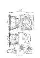
- FIG. 1 is a top plan view of a construction embodying my invention, a portion being broken away;
- Fig. 2 is a central, vertical, longitudinal section;
- Fig. 3 is a central, vertical transverse section;
- Fig. 4 is a perspective view of the damper and operating mechanism;
- Fig. 5 is a perspective view of the damper operating slide; and
- Figs. 6 and 7 are-sectional details of a portion of the fret-work surface plate.
- the side and end walls are formed as in tegral extensions on the bottom wall and are secured together along the substantially vertical corners in any suitable manner as for instance by folding the corner portions of the blank into engagement with the side or end walls or by cutting out the corner portions and securing one pair of walls to the other by flanges on one pair overlapping and riveted to the other pair of walls.
- the box is preferably somewhat smaller at the lower end than at the upper and the side and end walls at their upper edges are bent outwardly to form supporting flanges 13 adapted to rest upon the upper surface of the floor or on any other suitable support.
- the bottom wall 10 has a circular aperture therethrough at which is secured an annular collar 14: adapted to telescope with the cellar pipe.
- This collar 1A is substantially cylindrical and is of slightly smaller diameter than the opening in the bottom wall and is beaded inwardly to form a seat 15 for the lower surface of the bottom wall 10 about the opening in the latter.
- the free edge of the metal of the collar is then beaded or bent outwardly to form a flange 16 in engagementwith the upper surface of the wall 10 about the aperture in the latter.
- the collar is thus permanently attached to the register box and the means of attaching constitutes a reinforcing of the bottom wall 10 and a protection to the thin edge of the metal of said bottom wall about the opening.
- a damper 17 is provided which is preferably circular in form and of slightly larger diameter than the opening.
- the damper is secured to a transverse rod 18 serving as a pivot the projecting portions being journaled beneath small clips 19 secured to the bottom wall 10.
- One end of the rod is, bent to form a lever arm or crank 20 by means of which the damper may be turned.
- the damper has a peripheral portion 21 on one side of the pivot bent downwardly so as to seat against the Lmder side of the flange 15 when the damper is closed, and a peripheral portion 22 on the opposite side of the pivot rod 18bent upwardly to seat against the upper flange 16 when the damper is closed.
- the damper is thus effectively stopped when it reaches the closed position and the, bead of the collar 14 constitutes a seat for substantially the entire peripheral portion of the damper.
- the surface fretwork plate 23 is preferably formed, ofa
- This flange 2 1E is secured to the top plate by a lateral flange 25 secured to the top plate by suitable rivets 31 and adapted to he ever the flange 13.
- the peripheral portion of the plate 23 is preferably bent down a distance at least equal tothe thickness' of the flange 25 soas to closely engage with the upper surface of the floor or with the carpet or other covering thereon.
- 1 preferably provide reinforcing bars 26 disposed edge-wise in close engagement with the under-surface of the plate 23 and having their ends projecting into and supported by the flange 24. Preferably they are secured as is shown particularly in Figs. 6 and 7.
- A- portion of the bar at each end is cut away to form a shoulder 32 and a portion of the flange 24 1s bowed toward the bar and slotted from the bar upwardly.
- the bowed portion prevents lateral movement of" the bar and the flange prevents endwise movement.
- a lever 28 disposed substantially vertically and having its lowerend i'n engagement-with the crank or lever portion 20 of the damper pivot rod.
- the lower end of the lever slotted and receivesthe projecting end of" said rod.
- Fhe channel'sectionis supported by aroughened plate portion 30" disposed above the plate 23 and adapted to bemoved back and forth by pressing the foot thereon or in any other suitable manner;
- the plate 30 may be under-cut to a width corresponding to a slot in theplate 23 so as toinsure its proper position, prevent its accidental removal andguide it through its limit of. movement.
- lheflanges of the channel member 29 are of such length that the elevation of the top plate. may bevaried' thro'ugl-i quite appreciable limits .without disengaging said channel member from the lever 28 ⁇ .
- edges of the plate 23 may be placed upon the edge of a; carpet, rug; or other floor covering of varying thickness, and the mere placing of the plate inposition will produce the properoperative engagement of the slide and" the lever pipe, said collar having an inwardly directed bead receiving the box bottom at the pe-- riphery of the aperture, and serving to rig' idly connect said collar and said box.
- a register including a register box formed of sheet metal and having an apertured 'bottom, and an annular collar'below said box adapted for connection to asupply pipe, said collar-having an inwardly directedibead receiving the box bottom at the periphery of the aperture, and servingto rigidly connect said collar and said box, anda pivoted" damper seating uponsaid head.
- a register including a register box formed ofsheet metal'and havingan apertured bottom, and an annular collar below said box adapted for connection toa supply pipe, said collar having an inwardly directed bead receiving the box bottom at the peri'phery of the aperture, and serving torig idly connect.
- said collar and said box, and a damper pivotally connected to said boxbottomand having approximately one-half the peripheral portion thereof seating against the under surface of'said bead and having approximately one-half of the peripheral" portion seating against the upper half of said bead.
- a register including a register box, a-
- damper within the latter, a lever-pivoted 'to one wall of said box and operativelyconnectedto said damper, a reticulated plateatthe upper end of said box and aslide carried by said plate and normally opera tively connected to said lever, said slide be ing automatically detachable from said' l'e veruponthe raising of said plate.
- a register including areglst'er box, a
- damper therein, a reticulated surface plate spaced from said damper, a lever pivotall y supported i'ntermediateof'its ends, andhaving one end operatively connected to said damper and an operating member carried" by said plate and having depending fl'ang'esreceiving the upper end ofsaid lever therebetween, said member being automatically disengaged from said lever. upon the re.- moval of said plate. 7
Landscapes
- Engineering & Computer Science (AREA)
- Chemical & Material Sciences (AREA)
- Combustion & Propulsion (AREA)
- Mechanical Engineering (AREA)
- General Engineering & Computer Science (AREA)
- Rigid Containers With Two Or More Constituent Elements (AREA)
Description
C. S. HOOD.
REGISTER.
APPLICATION FILED AUG.6. 1913.
PatentedAng'. 24, 1915.
CYRUS S. HOOD, OF GORNING, NEW YORK.
REGISTER.
To all whom it may concern Be it known that I, CYRUS S. H001), a citizen of the United States, and resident of Corning, in the county of Steuben and State of New York, have invented certain new and useful Improvements in Registers, of which the following is a specification.
This invention relates to certain improvements in registers and more particularly to that general type shown in my prior Patent No. 633,455, granted September 19th, 1899.
The general objects of my present invention are to secure to a greater degree the results sought by my previous constructions, to reduce the cost of manufacture and to simplify the construction.
In my present improved construction the register box constitutes an important feature of my invention and is formed from a single piece of sheet metal or wrought iron.
The box has an opening in the bottom and a further feature of my invention involves the improved construction whereby the collar for the cellar pipe, is secured within this opening and at the same time is formed for the damper.
A further feature involves the mechanism for swinging the damper and insuring the proper engagement of the parts irrespective of slight variations in the elevation of the fret-work surface plate.
A further feature involves the slide in the face of this surface plate and another feature involves the construction of the surface plate itself.
These features as well as others will be described more in detail hereinafter and particularly pointed out in .the claims.
Reference is to be had to the accompanying drawings in which similar characters of reference indicate corresponding parts throughout the several views, and in which- Figure 1 is a top plan view of a construction embodying my invention, a portion being broken away; Fig. 2 is a central, vertical, longitudinal section; Fig. 3 is a central, vertical transverse section; Fig. 4 is a perspective view of the damper and operating mechanism; Fig. 5 is a perspective view of the damper operating slide; and Figs. 6 and 7 are-sectional details of a portion of the fret-work surface plate.
In the specific construction illustrated I form the entire register box of a single piece Specification of Letters Patent.
Patented Aug. 241, 1915.
- Application filed August 6, 1913. Serial No. 783,344.
of sheet metal including a bottom wall 10, end walls 11-11, and side walls 1212. The side and end walls are formed as in tegral extensions on the bottom wall and are secured together along the substantially vertical corners in any suitable manner as for instance by folding the corner portions of the blank into engagement with the side or end walls or by cutting out the corner portions and securing one pair of walls to the other by flanges on one pair overlapping and riveted to the other pair of walls. The box is preferably somewhat smaller at the lower end than at the upper and the side and end walls at their upper edges are bent outwardly to form supporting flanges 13 adapted to rest upon the upper surface of the floor or on any other suitable support. The bottom wall 10 has a circular aperture therethrough at which is secured an annular collar 14: adapted to telescope with the cellar pipe. This collar 1A is substantially cylindrical and is of slightly smaller diameter than the opening in the bottom wall and is beaded inwardly to form a seat 15 for the lower surface of the bottom wall 10 about the opening in the latter. The free edge of the metal of the collar is then beaded or bent outwardly to form a flange 16 in engagementwith the upper surface of the wall 10 about the aperture in the latter. The collar is thus permanently attached to the register box and the means of attaching constitutes a reinforcing of the bottom wall 10 and a protection to the thin edge of the metal of said bottom wall about the opening. A damper 17 is provided which is preferably circular in form and of slightly larger diameter than the opening. The damper is secured to a transverse rod 18 serving as a pivot the projecting portions being journaled beneath small clips 19 secured to the bottom wall 10. One end of the rod is, bent to form a lever arm or crank 20 by means of which the damper may be turned. Preferably the damper has a peripheral portion 21 on one side of the pivot bent downwardly so as to seat against the Lmder side of the flange 15 when the damper is closed, and a peripheral portion 22 on the opposite side of the pivot rod 18bent upwardly to seat against the upper flange 16 when the damper is closed. The damper is thus effectively stopped when it reaches the closed position and the, bead of the collar 14 constitutes a seat for substantially the entire peripheral portion of the damper. The surface fretwork plate 23 is preferably formed, ofa
box. This flange 2 1E is secured to the top plate by a lateral flange 25 secured to the top plate by suitable rivets 31 and adapted to he ever the flange 13. The peripheral portion of the plate 23 is preferably bent down a distance at least equal tothe thickness' of the flange 25 soas to closely engage with the upper surface of the floor or with the carpet or other covering thereon. For reinforcing and supporting the central portion of the plate, 1 preferably provide reinforcing bars 26 disposed edge-wise in close engagement with the under-surface of the plate 23 and having their ends projecting into and supported by the flange 24. Preferably they are secured as is shown particularly in Figs. 6 and 7. A- portion of the bar at each end is cut away to form a shoulder 32 and a portion of the flange 24 1s bowed toward the bar and slotted from the bar upwardly. The bowed portion prevents lateral movement of" the bar and the flange prevents endwise movement.
Pivoted to the inner surface of one of the end walls 11 I provide a lever 28 disposed substantially vertically and having its lowerend i'n engagement-with the crank or lever portion 20 of the damper pivot rod. As shownthe lower end of the leveris slotted and receivesthe projecting end of" said rod. Mounted" onthe surface-plateis a slide shown in detail in Figa 5; This slide includes, a channel section 29 with depending side flanges receiving; betweenthem the upper'end of the lever 28. Fhe channel'sectionis; supported by aroughened plate portion 30" disposed above the plate 23 and adapted to bemoved back and forth by pressing the foot thereon or in any other suitable manner; The plate 30 may be under-cut to a width corresponding to a slot in theplate 23 so as toinsure its proper position, prevent its accidental removal andguide it through its limit of. movement. lheflanges of the channel member 29 are of such length that the elevation of the top plate. may bevaried' thro'ugl-i quite appreciable limits .without disengaging said channel member from the lever 28}. Thus the edges of the plate 23 may be placed upon the edge of a; carpet, rug; or other floor covering of varying thickness, and the mere placing of the plate inposition will produce the properoperative engagement of the slide and" the lever pipe, said collar having an inwardly directed bead receiving the box bottom at the pe-- riphery of the aperture, and serving to rig' idly connect said collar and said box. 7
2. A register including a register box formed of sheet metal and having an apertured 'bottom, and an annular collar'below said box adapted for connection to asupply pipe, said collar-having an inwardly directedibead receiving the box bottom at the periphery of the aperture, and servingto rigidly connect said collar and said box, anda pivoted" damper seating uponsaid head.
3. A register including a register box formed ofsheet metal'and havingan apertured bottom, and an annular collar below said box adapted for connection toa supply pipe, said collar having an inwardly directed bead receiving the box bottom at the peri'phery of the aperture, and serving torig idly connect. said collar and said box, and a damper pivotally connected to said boxbottomand having approximately one-half the peripheral portion thereof seating against the under surface of'said bead and having approximately one-half of the peripheral" portion seating against the upper half of said bead.
4. A register including a register box, a-
damper within the latter, a lever-pivoted 'to one wall of said box and operativelyconnectedto said damper, a reticulated plateatthe upper end of said box and aslide carried by said plate and normally opera tively connected to said lever, said slide be ing automatically detachable from said' l'e veruponthe raising of said plate.
5, A register including areglst'er box, a
damper therein, a reticulated surface plate spaced from said damper, a lever pivotall y supported i'ntermediateof'its ends, andhaving one end operatively connected to said damper and an operating member carried" by said plate and having depending fl'ang'esreceiving the upper end ofsaid lever therebetween, said member being automatically disengaged from said lever. upon the re.- moval of said plate. 7
6L Airegisterincluding" a register box, a damper therein, a reticulated metal plate spaced from said damper, a lever pivotaxlly supportedintermediate of its ends and having one end operatively connected to said ben and State of New York this 24th day damper, a member carried by said plate and of July A. D. 1913.
operatively connected to the opposite end of said lever and automatically detachable 5 therefrom upon the removal of said plate from said box.
Signed at Corning in the county of Steu- CYRUS S. HOOD.
Witnesses:
ROBERT H. H001), ALFRED G. H001).
Copies of this patent may be obtained for five cents each, by addressing the Gommissioner of Patents, Washington, D. G.
Priority Applications (1)
| Application Number | Priority Date | Filing Date | Title |
|---|---|---|---|
| US78334413A US1151359A (en) | 1913-08-06 | 1913-08-06 | Register. |
Applications Claiming Priority (1)
| Application Number | Priority Date | Filing Date | Title |
|---|---|---|---|
| US78334413A US1151359A (en) | 1913-08-06 | 1913-08-06 | Register. |
Publications (1)
| Publication Number | Publication Date |
|---|---|
| US1151359A true US1151359A (en) | 1915-08-24 |
Family
ID=3219432
Family Applications (1)
| Application Number | Title | Priority Date | Filing Date |
|---|---|---|---|
| US78334413A Expired - Lifetime US1151359A (en) | 1913-08-06 | 1913-08-06 | Register. |
Country Status (1)
| Country | Link |
|---|---|
| US (1) | US1151359A (en) |
Cited By (7)
| Publication number | Priority date | Publication date | Assignee | Title |
|---|---|---|---|---|
| US4625632A (en) * | 1985-05-13 | 1986-12-02 | Owl Flex, Inc. | Damper and register box |
| US6066044A (en) * | 1998-12-08 | 2000-05-23 | Classic Manufacturing, Llc | Vent assembly |
| US6227962B1 (en) | 2000-03-08 | 2001-05-08 | Classic Manufacturing Nw, Llc | Vent coupler |
| US20060079171A1 (en) * | 2004-10-08 | 2006-04-13 | Ningbo Runner Industrial Corporation | Outlet vent controller of air conditioner |
| US20060089096A1 (en) * | 2004-10-27 | 2006-04-27 | Francotyp-Postalia Beteiligungs Ag | Security housing having ventilation openings |
| US20060199526A1 (en) * | 2005-02-08 | 2006-09-07 | Fettkether Keith J | Plastic register boot |
| US20070232216A1 (en) * | 2006-03-30 | 2007-10-04 | Toyoda Gosei Co., Ltd. | Register for air conditioning |
-
1913
- 1913-08-06 US US78334413A patent/US1151359A/en not_active Expired - Lifetime
Cited By (8)
| Publication number | Priority date | Publication date | Assignee | Title |
|---|---|---|---|---|
| US4625632A (en) * | 1985-05-13 | 1986-12-02 | Owl Flex, Inc. | Damper and register box |
| US6066044A (en) * | 1998-12-08 | 2000-05-23 | Classic Manufacturing, Llc | Vent assembly |
| US6227962B1 (en) | 2000-03-08 | 2001-05-08 | Classic Manufacturing Nw, Llc | Vent coupler |
| US20060079171A1 (en) * | 2004-10-08 | 2006-04-13 | Ningbo Runner Industrial Corporation | Outlet vent controller of air conditioner |
| US20060089096A1 (en) * | 2004-10-27 | 2006-04-27 | Francotyp-Postalia Beteiligungs Ag | Security housing having ventilation openings |
| US7094143B2 (en) * | 2004-10-27 | 2006-08-22 | Francotyp-Postalia Gmbh | Security housing having ventilation openings |
| US20060199526A1 (en) * | 2005-02-08 | 2006-09-07 | Fettkether Keith J | Plastic register boot |
| US20070232216A1 (en) * | 2006-03-30 | 2007-10-04 | Toyoda Gosei Co., Ltd. | Register for air conditioning |
Similar Documents
| Publication | Publication Date | Title |
|---|---|---|
| US1151359A (en) | Register. | |
| US1053438A (en) | Dust-pan. | |
| US1220422A (en) | Coal-receptacle. | |
| US1049199A (en) | Collapsible drinking-cup. | |
| US660443A (en) | Lid for cooking utensils. | |
| US429551A (en) | Bake-pan | |
| US692103A (en) | Paste-bucket and stand therefor. | |
| US2516358A (en) | Detachable damper for convector heaters | |
| US628717A (en) | Culinary utensil. | |
| US477974A (en) | Stew-pan | |
| US1525652A (en) | Container | |
| US486865A (en) | Warm-air register | |
| US900705A (en) | Dust-pan. | |
| US58460A (en) | Improvement in spiders | |
| US232984A (en) | Register-knob | |
| US363997A (en) | Ralph ely | |
| US756330A (en) | Camp-stove. | |
| US1021066A (en) | Saucepan-cover. | |
| US676603A (en) | Lid for cooking utensils. | |
| US907370A (en) | Corn-popper. | |
| US2177824A (en) | Stove top construction | |
| US814888A (en) | Hot-air register. | |
| US906272A (en) | Cooking utensil. | |
| US1147648A (en) | Portable shower-bath. | |
| US352975A (en) | Sad-iron |