US11500114B2 - Ubiquitous real-time fracture monitoring - Google Patents
Ubiquitous real-time fracture monitoring Download PDFInfo
- Publication number
- US11500114B2 US11500114B2 US16/408,396 US201916408396A US11500114B2 US 11500114 B2 US11500114 B2 US 11500114B2 US 201916408396 A US201916408396 A US 201916408396A US 11500114 B2 US11500114 B2 US 11500114B2
- Authority
- US
- United States
- Prior art keywords
- fracture
- poroelastic
- poroelastic pressure
- simulated
- pressure response
- Prior art date
- Legal status (The legal status is an assumption and is not a legal conclusion. Google has not performed a legal analysis and makes no representation as to the accuracy of the status listed.)
- Active, expires
Links
Images


Classifications
-
- G—PHYSICS
- G01—MEASURING; TESTING
- G01V—GEOPHYSICS; GRAVITATIONAL MEASUREMENTS; DETECTING MASSES OR OBJECTS; TAGS
- G01V1/00—Seismology; Seismic or acoustic prospecting or detecting
- G01V1/28—Processing seismic data, e.g. for interpretation or for event detection
- G01V1/282—Application of seismic models, synthetic seismograms
-
- G—PHYSICS
- G06—COMPUTING OR CALCULATING; COUNTING
- G06F—ELECTRIC DIGITAL DATA PROCESSING
- G06F30/00—Computer-aided design [CAD]
- G06F30/20—Design optimisation, verification or simulation
-
- E—FIXED CONSTRUCTIONS
- E21—EARTH OR ROCK DRILLING; MINING
- E21B—EARTH OR ROCK DRILLING; OBTAINING OIL, GAS, WATER, SOLUBLE OR MELTABLE MATERIALS OR A SLURRY OF MINERALS FROM WELLS
- E21B43/00—Methods or apparatus for obtaining oil, gas, water, soluble or meltable materials or a slurry of minerals from wells
- E21B43/25—Methods for stimulating production
- E21B43/26—Methods for stimulating production by forming crevices or fractures
-
- E—FIXED CONSTRUCTIONS
- E21—EARTH OR ROCK DRILLING; MINING
- E21B—EARTH OR ROCK DRILLING; OBTAINING OIL, GAS, WATER, SOLUBLE OR MELTABLE MATERIALS OR A SLURRY OF MINERALS FROM WELLS
- E21B47/00—Survey of boreholes or wells
- E21B47/06—Measuring temperature or pressure
-
- E—FIXED CONSTRUCTIONS
- E21—EARTH OR ROCK DRILLING; MINING
- E21B—EARTH OR ROCK DRILLING; OBTAINING OIL, GAS, WATER, SOLUBLE OR MELTABLE MATERIALS OR A SLURRY OF MINERALS FROM WELLS
- E21B49/00—Testing the nature of borehole walls; Formation testing; Methods or apparatus for obtaining samples of soil or well fluids, specially adapted to earth drilling or wells
- E21B49/003—Testing the nature of borehole walls; Formation testing; Methods or apparatus for obtaining samples of soil or well fluids, specially adapted to earth drilling or wells by analysing drilling variables or conditions
-
- E—FIXED CONSTRUCTIONS
- E21—EARTH OR ROCK DRILLING; MINING
- E21B—EARTH OR ROCK DRILLING; OBTAINING OIL, GAS, WATER, SOLUBLE OR MELTABLE MATERIALS OR A SLURRY OF MINERALS FROM WELLS
- E21B49/00—Testing the nature of borehole walls; Formation testing; Methods or apparatus for obtaining samples of soil or well fluids, specially adapted to earth drilling or wells
- E21B49/008—Testing the nature of borehole walls; Formation testing; Methods or apparatus for obtaining samples of soil or well fluids, specially adapted to earth drilling or wells by injection test; by analysing pressure variations in an injection or production test, e.g. for estimating the skin factor
-
- G—PHYSICS
- G01—MEASURING; TESTING
- G01V—GEOPHYSICS; GRAVITATIONAL MEASUREMENTS; DETECTING MASSES OR OBJECTS; TAGS
- G01V1/00—Seismology; Seismic or acoustic prospecting or detecting
- G01V1/40—Seismology; Seismic or acoustic prospecting or detecting specially adapted for well-logging
- G01V1/44—Seismology; Seismic or acoustic prospecting or detecting specially adapted for well-logging using generators and receivers in the same well
- G01V1/48—Processing data
- G01V1/50—Analysing data
-
- G—PHYSICS
- G01—MEASURING; TESTING
- G01V—GEOPHYSICS; GRAVITATIONAL MEASUREMENTS; DETECTING MASSES OR OBJECTS; TAGS
- G01V1/00—Seismology; Seismic or acoustic prospecting or detecting
- G01V1/40—Seismology; Seismic or acoustic prospecting or detecting specially adapted for well-logging
- G01V1/42—Seismology; Seismic or acoustic prospecting or detecting specially adapted for well-logging using generators in one well and receivers elsewhere or vice versa
-
- G—PHYSICS
- G01—MEASURING; TESTING
- G01V—GEOPHYSICS; GRAVITATIONAL MEASUREMENTS; DETECTING MASSES OR OBJECTS; TAGS
- G01V20/00—Geomodelling in general
-
- G—PHYSICS
- G01—MEASURING; TESTING
- G01V—GEOPHYSICS; GRAVITATIONAL MEASUREMENTS; DETECTING MASSES OR OBJECTS; TAGS
- G01V2210/00—Details of seismic processing or analysis
- G01V2210/10—Aspects of acoustic signal generation or detection
- G01V2210/12—Signal generation
- G01V2210/123—Passive source, e.g. microseismics
- G01V2210/1234—Hydrocarbon reservoir, e.g. spontaneous or induced fracturing
-
- G—PHYSICS
- G01—MEASURING; TESTING
- G01V—GEOPHYSICS; GRAVITATIONAL MEASUREMENTS; DETECTING MASSES OR OBJECTS; TAGS
- G01V2210/00—Details of seismic processing or analysis
- G01V2210/10—Aspects of acoustic signal generation or detection
- G01V2210/14—Signal detection
- G01V2210/142—Receiver location
- G01V2210/1429—Subsurface, e.g. in borehole or below weathering layer or mud line
-
- G—PHYSICS
- G01—MEASURING; TESTING
- G01V—GEOPHYSICS; GRAVITATIONAL MEASUREMENTS; DETECTING MASSES OR OBJECTS; TAGS
- G01V2210/00—Details of seismic processing or analysis
- G01V2210/60—Analysis
- G01V2210/62—Physical property of subsurface
- G01V2210/624—Reservoir parameters
-
- G—PHYSICS
- G01—MEASURING; TESTING
- G01V—GEOPHYSICS; GRAVITATIONAL MEASUREMENTS; DETECTING MASSES OR OBJECTS; TAGS
- G01V2210/00—Details of seismic processing or analysis
- G01V2210/60—Analysis
- G01V2210/62—Physical property of subsurface
- G01V2210/624—Reservoir parameters
- G01V2210/6242—Elastic parameters, e.g. Young, Lamé or Poisson
-
- G—PHYSICS
- G01—MEASURING; TESTING
- G01V—GEOPHYSICS; GRAVITATIONAL MEASUREMENTS; DETECTING MASSES OR OBJECTS; TAGS
- G01V2210/00—Details of seismic processing or analysis
- G01V2210/60—Analysis
- G01V2210/62—Physical property of subsurface
- G01V2210/624—Reservoir parameters
- G01V2210/6244—Porosity
-
- G—PHYSICS
- G01—MEASURING; TESTING
- G01V—GEOPHYSICS; GRAVITATIONAL MEASUREMENTS; DETECTING MASSES OR OBJECTS; TAGS
- G01V2210/00—Details of seismic processing or analysis
- G01V2210/60—Analysis
- G01V2210/62—Physical property of subsurface
- G01V2210/624—Reservoir parameters
- G01V2210/6248—Pore pressure
-
- G—PHYSICS
- G01—MEASURING; TESTING
- G01V—GEOPHYSICS; GRAVITATIONAL MEASUREMENTS; DETECTING MASSES OR OBJECTS; TAGS
- G01V2210/00—Details of seismic processing or analysis
- G01V2210/60—Analysis
- G01V2210/64—Geostructures, e.g. in 3D data cubes
- G01V2210/646—Fractures
-
- G—PHYSICS
- G01—MEASURING; TESTING
- G01V—GEOPHYSICS; GRAVITATIONAL MEASUREMENTS; DETECTING MASSES OR OBJECTS; TAGS
- G01V2210/00—Details of seismic processing or analysis
- G01V2210/60—Analysis
- G01V2210/66—Subsurface modeling
- G01V2210/663—Modeling production-induced effects
Definitions
- the present invention relates generally to recovery of hydrocarbons from unconventional reservoirs. More particularly, but not by way of limitation, embodiments of the present invention include tools and methods for real-time monitoring of hydraulic fracture geometry by quickly interrogating and finding a match in a database of poroelastic pressure signatures.
- Horizontal wellbore may be formed to reach desired regions of a formation not readily accessible.
- multiple stages in some cases dozens of stages
- fracturing can occur in a single well. These fracture stages are implemented in a single well bore to increase production levels and provide effective drainage. In many cases, there can also be multiple wells per location.
- microseismic imaging there are several conventional techniques (e.g., microseismic imaging) for characterizing geometry, location, and complexity of hydraulic fractures.
- microseismic imaging technique can suffer from a number of issues which limit its effectiveness. While microseismic imaging can capture shear failure of natural fractures activated during well stimulation, it is typically less effective at capturing tensile opening of hydraulic fractures itself. Moreover, there is considerable debate on interpretations of microseismic events as it relates to hydraulic fractures.
- the present invention relates generally to recovery of hydrocarbons from unconventional reservoirs. More particularly, but not by way of limitation, embodiments of the present invention include tools and methods for real-time monitoring of hydraulic fracture geometry by characterizing main characteristics of poroelastic responses measured during hydraulic stimulation and quickly interrogating and finding a match in database of poroelastic pressure signatures.
- the present invention can monitor evolution of reservoir stresses throughout lifetime of a field during hydraulic fracturing. Measuring and/or identifying favorable stress regimes can help maximize efficiency of multi-stage fracture treatments in shale plays.
- One example of a method for characterizing a subterranean formation includes: a) simulating a poroelastic pressure response of known fracture geometry utilizing a geomechanical model to generate a simulated poroelastic pressure response; b) repeating a) to compile a database of simulated poroelastic pressure responses; c) measuring a poroelastic pressure response of the subterranean formation during a hydraulic fracturing operation to generate a measured poroelastic pressure response; d) identifying a closest simulated poroelastic pressure response in the library of simulated poroelastic pressure response; and e) estimating a geometrical parameter of a fracture or fractures in the subterranean formation based on the closest simulated poroelastic pressure response.
- Another example of a method for characterizing a subterranean formation includes: a) compiling a database of simulated poroelastic pressure responses of stimulated fractures, wherein the library is stored in a non-transitory computer storage medium; b) obtaining a poroelastic pressure response of the subterranean formation during a hydraulic fracturing operation to generate a measured poroelastic pressure response; c) using a computer-processor to query the database of simulated poroelastic pressure responses to identify a closest simulated poroelastic pressure response; and d) estimating a geometrical parameter of a fracture or fractures in the subterranean formation based on the closest simulated poroelastic pressure response.
- FIGS. 1A-1B illustrates poroelastic behavior in high permeability ( FIG. 1A ) and low permeability ( FIG. 1B ) systems.
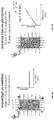
- FIGS. 2A-2B illustrate a set simulated poroelastic pressure response curves of a known fracture geometry and observation points.
- FIG. 3 illustrates an example of multiple well configuration during hydraulic fracturing.
- FIGS. 4A-4D illustrates downhole monitor vertical well configurations suitable for measuring poroelastic pressure response according to one or more embodiments.
- FIG. 5 illustrates downhole well configuration suitable for measuring poroelastic pressure response in which the pressure gauge is installed outside of the casing according to one or more embodiments.
- FIGS. 6A-6C illustrate horizontal well configurations suitable for measuring poroelastic pressure response according to one or more embodiments.
- FIG. 7 illustrates a workflow for one or more embodiments of the present invention.
- the present invention relates generally to recovery of hydrocarbons from unconventional reservoirs. More particularly, but not by way of limitation, embodiments of the present invention include tools and methods for real-time monitoring of hydraulic fracture geometry by quickly interrogating and finding a match in a database of poroelastic pressure signatures.
- One of the goals of this technology is to enable cost effective characterization of the induced fracture system on virtually every well with little to no impact on ongoing operations. It has the potential to be used universally during fracturing operations in shale wells.
- Another advantage capitalizes on the resulting quick speed of pressure data interpretation. For example, by training a neural network using synthetic cases of numerically-generated pressure response (for which induced-fracture characteristics are known), the present invention can quickly relate the measured poroelastic pressure response to fracture geometries and generate a real-time map. Other advantages will be apparent from the disclosure herein.
- poroelastic pressure response In low permeability systems (such as shale), the rock is closed to fluid mass transfer which causes the pore pressure to increase ( FIG. 1B ).
- One can measure the resulting poroelastic pressure response which can also be defined as a pressure change in the subsurface resulting from a change in volumetric stresses. A change in volumetric stress can be related back to a geomechanical phenomena.
- the poroelastic pressure response is a pressure signature that is not related to flow or hydraulic communication with the stimulated well but is a proxy for mechanical deformation and/or stress interference.
- FIG. 2B shows a set of numerically simulated poroelastic pressure response curves to fracture propagation and closure, at multiple locations in the reservoir.
- FIG. 2A illustrate the hydraulic fracture and observation points corresponding to the curves.
- the fracture dimensions at the end of propagation are 775 ft (half-length) by 160 ft (height).
- a decrease in pressure is observed resulting from tensile stresses.
- the squeezing effect will produce an increase in pressure along observation points (150 ft, 300 ft, 450 ft, 600 ft, 750 ft from where the fracture initiates).
- poroelastic pressure declines due to leak-off and closure of the hydraulic fracture.
- FIG. 3 illustrates a common hydraulic fracturing setup that includes an active/stimulated well, offset well, and monitor well. As shown, a pressure gauge can be installed at the surface in the offset well and/or monitor well (not shown).
- the downhole well configurations of FIGS. 4A-4D , FIG. 5 , and FIG. 6 can be viewed within the context of FIG. 3 .
- FIGS. 4A-4D illustrate different vertical well configurations that allow measurement of poroelastic pressure response through or in a monitor well.
- the hydraulic fractures were generated in a nearby active well.
- FIG. 4A shows a single zone configuration of a perforated monitor well (unstimulated). As shown, a pressure gauge can be installed at the surface to measure poroelastic pressure response through the perforations.
- FIG. 4B shows a multi-zone configuration of a perforated monitor well (unstimulated). As shown, each zone has been sealed with a solid plug. This allows pressure gauges to be installed at various locations (e.g., surface, downhole within each zone, etc.) and locally measure poroelastic pressure response.
- FIG. 4A shows a single zone configuration of a perforated monitor well (unstimulated). As shown, a pressure gauge can be installed at the surface to measure poroelastic pressure response through the perforations.
- FIG. 4B shows a multi-zone configuration of a perforated
- FIG. 4C shows a single zone configuration of a stimulated monitor well.
- FIG. 4D shows a multi-zone configuration of a stimulated monitor well. In both of these configurations the poroelastic pressure response is measured through the monitor well's hydraulic fractures and perforations.
- FIG. 5 illustrates another vertical well measurement configuration.
- the pressure gauge is installed outside of the casing and can measure poroelastic pressure response through the porous rock formation.
- FIG. 6A-6C illustrate different horizontal well configurations.
- FIG. 6A shows pressure gauges installed outside of the casing at multiple reservoir locations.
- FIG. 6B shows poroelastic pressure measurements taken at the surface through the toe prep.
- FIG. 6C shows how pressure measurement can be taken at the surface through a fracture stage.
- the present invention automates processing of active/offset well poroelastic pressure data by extracting its essential characteristics (e.g., time-lag, magnitude, slope) and accelerating its interpretation to provide a real-time interpreted map of each fracturing stage.
- the interpretations can include estimates of physical characteristics such as length, height, orientation, fracture asymmetry, residual width from proppant, and the like. These estimates can be based on a database or library of previously studied poroelastic pressure response (“pressure signatures”).
- the database will include a searchable library of simulated or modeled pressure signatures (e.g., FIG. 2 ).
- the database may include full or partial pressure signatures.
- the database also includes pressure signatures obtained from field data (e.g, microseismic monitoring, distributed acoustic/temperature sensing, tiltmeter monitoring, fluid and proppant tracers, production logs, etc.).
- a user can query the database based on any one or combination of the essential characteristics (i.e., time-lag, magnitude, slope, etc.) to find a match.
- the process is analogous to finding a fingerprint match where several key features of the measured poroelastic pressure response is compared against a database of poroelastic pressure responses to find a match.
- poroelastic pressure data may be processed in real time to provide an immediate assessment of the SRV, thus enabling decisions “on the fly” and even testing of several completion designs on a single well or pad.
- the present invention provides a quick feedback mechanism for understanding geometry of induced fractures and its relationship to completion designs. This allows engineers to make changes to fracturing design (e.g., rate, proppant concentration, volume) on the fly and optimize completion in real time. Affordable, real-time, systematic fracture monitoring enabled by physics-informed data analytics and/or machine learning would considerably reduce learning time and allow faster convergence to optimum development scenarios.
- fracturing design e.g., rate, proppant concentration, volume
- FIG. 7 illustrates a real-time workflow of fracture mapping and completion optimization based on interpretation of poroelastic pressure responses during hydraulic stimulation of a field.
- the first step of the workflow involves extracting essential characteristics of the reservoir or field from the acquired poroelastic pressure responses (pressure versus time). These essential characteristics can be obtained by measuring the poroelastic pressure response after stimulation has begun. Some of these characteristics include elapsed time to reach maximum pressure ( ⁇ t max ), elapsed time to reach minimum pressure ( ⁇ t min ), maximum deviation in poroelastic pressure ( ⁇ p max ), minimum deviation in poroelastic pressure ( ⁇ p min ), and maximum slope (max ⁇ p/ ⁇ t).
- the poroelastic response database can include results from numerical simulations of poroelastic response of known fracture dimension, interpretation of prior field poroelastic responses, and other field fracture diagnostic data.
- the database can be queried using any of the essential characteristics, fracture dimension or dimensions, or even the shape of the poroelastic response curve. Integration of the poroelastic response database with machine learning capabilities (e.g., neural networks) can improve accuracy of fracture dimension predictions.
- dimensions length, height, width, orientation, etc.
- dimensions can be estimated.
- the database can be augmented or tagged with additional parameters such as best completion design parameters (injection rate, fluid type/volume, proppant type/volume, cluster/stage spacing, etc.) and geological parameters (landing depth, mechanical properties, etc.) and well performance.
- a completion engineer can query the database to obtain not only fracture dimensions but suggested completion parameters while considering factors such as geological parameters and well performance.
- the completion design is improved in real-time.
Landscapes
- Engineering & Computer Science (AREA)
- Physics & Mathematics (AREA)
- Life Sciences & Earth Sciences (AREA)
- Geology (AREA)
- Mining & Mineral Resources (AREA)
- Environmental & Geological Engineering (AREA)
- General Life Sciences & Earth Sciences (AREA)
- Fluid Mechanics (AREA)
- Geochemistry & Mineralogy (AREA)
- General Physics & Mathematics (AREA)
- Theoretical Computer Science (AREA)
- Remote Sensing (AREA)
- Geophysics (AREA)
- Acoustics & Sound (AREA)
- Chemical & Material Sciences (AREA)
- Analytical Chemistry (AREA)
- Evolutionary Computation (AREA)
- Geometry (AREA)
- General Engineering & Computer Science (AREA)
- Computer Hardware Design (AREA)
- Measuring Fluid Pressure (AREA)
- Geophysics And Detection Of Objects (AREA)
- Investigating Strength Of Materials By Application Of Mechanical Stress (AREA)
Abstract
Description
Claims (20)
Priority Applications (2)
| Application Number | Priority Date | Filing Date | Title |
|---|---|---|---|
| US16/408,396 US11500114B2 (en) | 2018-05-09 | 2019-05-09 | Ubiquitous real-time fracture monitoring |
| US18/045,255 US20230058915A1 (en) | 2018-05-09 | 2022-10-10 | Ubiquitous real-time fracture monitoring |
Applications Claiming Priority (3)
| Application Number | Priority Date | Filing Date | Title |
|---|---|---|---|
| US201862669077P | 2018-05-09 | 2018-05-09 | |
| US201862669065P | 2018-05-09 | 2018-05-09 | |
| US16/408,396 US11500114B2 (en) | 2018-05-09 | 2019-05-09 | Ubiquitous real-time fracture monitoring |
Related Child Applications (1)
| Application Number | Title | Priority Date | Filing Date |
|---|---|---|---|
| US18/045,255 Continuation US20230058915A1 (en) | 2018-05-09 | 2022-10-10 | Ubiquitous real-time fracture monitoring |
Publications (2)
| Publication Number | Publication Date |
|---|---|
| US20190346579A1 US20190346579A1 (en) | 2019-11-14 |
| US11500114B2 true US11500114B2 (en) | 2022-11-15 |
Family
ID=68464637
Family Applications (4)
| Application Number | Title | Priority Date | Filing Date |
|---|---|---|---|
| US16/408,396 Active 2041-01-22 US11500114B2 (en) | 2018-05-09 | 2019-05-09 | Ubiquitous real-time fracture monitoring |
| US16/408,405 Active 2039-07-02 US11209558B2 (en) | 2018-05-09 | 2019-05-09 | Measurement of poroelastic pressure response |
| US17/554,986 Active US11921246B2 (en) | 2018-05-09 | 2021-12-17 | Measurement of poroelastic pressure response |
| US18/429,025 Active US12541034B2 (en) | 2018-05-09 | 2024-01-31 | Measurement of poroelastic pressure response |
Family Applications After (3)
| Application Number | Title | Priority Date | Filing Date |
|---|---|---|---|
| US16/408,405 Active 2039-07-02 US11209558B2 (en) | 2018-05-09 | 2019-05-09 | Measurement of poroelastic pressure response |
| US17/554,986 Active US11921246B2 (en) | 2018-05-09 | 2021-12-17 | Measurement of poroelastic pressure response |
| US18/429,025 Active US12541034B2 (en) | 2018-05-09 | 2024-01-31 | Measurement of poroelastic pressure response |
Country Status (5)
| Country | Link |
|---|---|
| US (4) | US11500114B2 (en) |
| CA (2) | CA3099731A1 (en) |
| CL (2) | CL2020002556A1 (en) |
| CO (2) | CO2020013970A2 (en) |
| WO (2) | WO2019217763A1 (en) |
Cited By (1)
| Publication number | Priority date | Publication date | Assignee | Title |
|---|---|---|---|---|
| US11725500B2 (en) | 2013-12-18 | 2023-08-15 | Conocophillips Company | Method for determining hydraulic fracture orientation and dimension |
Families Citing this family (10)
| Publication number | Priority date | Publication date | Assignee | Title |
|---|---|---|---|---|
| CA3045295A1 (en) | 2016-11-29 | 2018-06-07 | Nicolas P. Roussel | Methods for shut-in pressure escalation analysis |
| US11365617B1 (en) | 2017-01-24 | 2022-06-21 | Devon Energy Corporation | Systems and methods for controlling fracturing operations using monitor well pressure |
| US11028679B1 (en) | 2017-01-24 | 2021-06-08 | Devon Energy Corporation | Systems and methods for controlling fracturing operations using monitor well pressure |
| US11500114B2 (en) | 2018-05-09 | 2022-11-15 | Conocophillips Company | Ubiquitous real-time fracture monitoring |
| US11619126B2 (en) | 2020-12-04 | 2023-04-04 | Halliburton Energy Services, Inc. | Estimate active-adjacent borehole interference severity |
| EP4278065A4 (en) | 2021-01-15 | 2024-06-26 | ConocoPhillips Company | Hydraulic integrity analysis |
| WO2022173971A1 (en) | 2021-02-10 | 2022-08-18 | Conocophillips Company | Automated initial shut-in pressure estimation |
| US11859490B2 (en) | 2021-08-19 | 2024-01-02 | Devon Energy Corporation | Systems and methods for monitoring fracturing operations using monitor well flow |
| US20250122799A1 (en) * | 2023-04-11 | 2025-04-17 | Conocophllips Company | Fracture impact characterization |
| CN117633409B (en) * | 2024-01-25 | 2024-04-09 | 中国科学院地质与地球物理研究所 | Method, system and equipment for calculating shale oil and gas reservoir fracture network seepage parameters |
Citations (54)
| Publication number | Priority date | Publication date | Assignee | Title |
|---|---|---|---|---|
| US3933205A (en) | 1973-10-09 | 1976-01-20 | Othar Meade Kiel | Hydraulic fracturing process using reverse flow |
| US4802144A (en) | 1986-03-20 | 1989-01-31 | Applied Geomechanics, Inc. | Hydraulic fracture analysis method |
| US4858130A (en) | 1987-08-10 | 1989-08-15 | The Board Of Trustees Of The Leland Stanford Junior University | Estimation of hydraulic fracture geometry from pumping pressure measurements |
| US5005643A (en) | 1990-05-11 | 1991-04-09 | Halliburton Company | Method of determining fracture parameters for heterogenous formations |
| US5360066A (en) | 1992-12-16 | 1994-11-01 | Halliburton Company | Method for controlling sand production of formations and for optimizing hydraulic fracturing through perforation orientation |
| US20030042016A1 (en) | 2000-01-24 | 2003-03-06 | Vinegar Harold J. | Wireless communication using well casing |
| US20040129418A1 (en) | 2002-08-15 | 2004-07-08 | Schlumberger Technology Corporation | Use of distributed temperature sensors during wellbore treatments |
| WO2005124395A2 (en) | 2004-06-18 | 2005-12-29 | Services Petroliers Schlumberger | Methods and apparatus for measuring streaming potentials and determining earth formation characteristics |
| US20060102342A1 (en) | 2004-11-12 | 2006-05-18 | Loyd East | Fracture characterization using reservoir monitoring devices |
| US20060155473A1 (en) | 2005-01-08 | 2006-07-13 | Halliburton Energy Services, Inc. | Method and system for determining formation properties based on fracture treatment |
| US20070079652A1 (en) | 2005-10-07 | 2007-04-12 | Craig David P | Methods and systems for determining reservoir properties of subterranean formations |
| US20070235181A1 (en) | 2003-09-16 | 2007-10-11 | Commonwealth Scientific And Industrial Reseach Organisation | Hydraulic Fracturing |
| US20090090505A1 (en) | 2006-08-09 | 2009-04-09 | Mcdaniel Robert R | Method and tool for determination of fracture geometry in subterranean formations based on in-situ neutron activation analysis |
| US20100004906A1 (en) | 2006-09-20 | 2010-01-07 | Searles Kevin H | Fluid Injection Management Method For Hydrocarbon Recovery |
| EP2163724A2 (en) | 2008-09-10 | 2010-03-17 | Schlumberger Technology B.V. | Measuring properties of low permeability formations |
| US7774140B2 (en) | 2004-03-30 | 2010-08-10 | Halliburton Energy Services, Inc. | Method and an apparatus for detecting fracture with significant residual width from previous treatments |
| US20100250216A1 (en) | 2009-03-24 | 2010-09-30 | Chevron U.S.A. Inc. | System and method for characterizing fractures in a subsurface reservoir |
| US20100314104A1 (en) | 2007-09-13 | 2010-12-16 | M-I L.L.C. | Method of using pressure signatures to predict injection well anomalies |
| US20110017458A1 (en) | 2009-07-24 | 2011-01-27 | Halliburton Energy Services, Inc. | Method for Inducing Fracture Complexity in Hydraulically Fractured Horizontal Well Completions |
| WO2011022012A1 (en) | 2009-08-20 | 2011-02-24 | Halliburton Energy Services, Inc. | Fracture characterization using directional electromagnetic resistivity measurements |
| US20110067857A1 (en) | 2009-09-23 | 2011-03-24 | Schlumberger Technology Corporation | Determining properties of a subterranean structure during hydraulic fracturing |
| US20110120712A1 (en) | 2009-07-30 | 2011-05-26 | Halliburton Energy Services, Inc. | Increasing fracture complexity in ultra-low permeable subterranean formation using degradable particulate |
| US20110272147A1 (en) | 2008-08-18 | 2011-11-10 | Beasley Craig J | Active Seismic Monitoring of Fracturing Operations and Determining Characteristics of a Subterranean Body Using Pressure Data and Seismic Data |
| US8204727B2 (en) | 2008-09-19 | 2012-06-19 | Chevron U.S.A. Inc. | Computer-implemented systems and methods for use in modeling a geomechanical reservoir system |
| US8210257B2 (en) | 2010-03-01 | 2012-07-03 | Halliburton Energy Services Inc. | Fracturing a stress-altered subterranean formation |
| US20120168180A1 (en) | 2010-12-29 | 2012-07-05 | Johnson Charles C | Isolation of Zones for Fracturing Using Removable Plugs |
| WO2012173608A1 (en) | 2011-06-15 | 2012-12-20 | Halliburton Energy Services, Inc. | Systems and methods for measuring parameters of a formation |
| US20120325462A1 (en) | 2011-06-24 | 2012-12-27 | Roussel Nicolas P | Method for Determining Spacing of Hydraulic Fractures in a Rock Formation |
| WO2013008195A2 (en) | 2011-07-11 | 2013-01-17 | Schlumberger Canada Limited | System and method for performing wellbore stimulation operations |
| US20130087325A1 (en) | 2011-10-09 | 2013-04-11 | Saudi Arabian Oil Company | Method For Real-Time Monitoring and Transmitting Hydraulic Fracture Seismic Events to Surface Using the Pilot Hole of the Treatment Well as the Monitoring Well |
| US20130186688A1 (en) | 2011-07-22 | 2013-07-25 | John C. Rasmus | Methods for determining formation strength of a wellbore |
| US20130211807A1 (en) | 2010-10-27 | 2013-08-15 | Elizabeth Land Templeton-Barrett | Method and System for Fracturing a Formation |
| US20130277050A1 (en) | 2012-04-24 | 2013-10-24 | Schlumberger Technology Corporation | Interacting hydraulic fracturing |
| US20130298665A1 (en) | 2010-12-21 | 2013-11-14 | Michael Charles Minchau | System and method for monitoring strain & pressure |
| US20140048270A1 (en) | 2012-08-20 | 2014-02-20 | Texas Tech University System | Methods and Devices for Hydraulic Fracturing Design and Optimization: A Modification to Zipper Frac |
| US20140067353A1 (en) | 2012-09-05 | 2014-03-06 | Stratagen | Wellbore completion and hydraulic fracturing optimization methods and associated systems |
| US20140083681A1 (en) * | 2012-09-24 | 2014-03-27 | Stewart Thomas Taylor | Seismic monitoring system and method |
| US20140145716A1 (en) | 2011-07-12 | 2014-05-29 | Halliburton Energy Services, Inc. | Nmr tracking of injected fluids |
| WO2014126484A1 (en) | 2013-02-18 | 2014-08-21 | Auckland Uniservices Limited | Method and system for identifying zones of high fracture connectivity in a geologic/geothermal reservoir |
| US20150075775A1 (en) | 2013-09-17 | 2015-03-19 | Brett C. Davidson | Method for determining regions for stimulation along two parallel adjacent wellbores in a hydrocarbon formation |
| US20150176394A1 (en) | 2013-12-18 | 2015-06-25 | Conocophillips Company | Method for determining hydraulic fracture orientation and dimension |
| US20160003020A1 (en) | 2013-02-04 | 2016-01-07 | Board Of Regents, The University Of Texas System | Methods for time-delayed fracturing in hydrocarbon formations |
| US20160196367A1 (en) | 2014-07-15 | 2016-07-07 | Petroleum Fractured Reservoir Solutions, Llc | Discrete irregular cellular models for simulating the development of fractured reservoirs |
| US20160238736A1 (en) | 2014-04-28 | 2016-08-18 | Halliburton Energy Services, Inc. | Downhole Evaluation with Neutron Activation Measurement |
| WO2016175844A1 (en) | 2015-04-30 | 2016-11-03 | Landmark Graphics Corporation | Shale geomechanics for multi-stage hydraulic fracturing optimization in resource shale and tight plays |
| US20160334542A1 (en) | 2015-05-13 | 2016-11-17 | Conocophillips Company | Time corrections for drilling data |
| WO2016193733A1 (en) | 2015-06-03 | 2016-12-08 | Geomec Engineering Ltd | A downhole pressure measuring tool with a high sampling rate |
| US20160357883A1 (en) | 2011-11-04 | 2016-12-08 | Schlumberger Technology Corporation | Stacked height growth fracture modeling |
| US20160370260A1 (en) | 2015-06-19 | 2016-12-22 | Conocophillips Company | System and method for event detection using streaming signals |
| US20160369612A1 (en) | 2015-06-18 | 2016-12-22 | Conocophillips Company | Characterization of whirl drilling dysfunction |
| US20180003033A1 (en) * | 2016-07-03 | 2018-01-04 | Reveal Energy Services, Inc. | Mapping of fracture geometries in a multi-well stimulation process |
| US20180148999A1 (en) | 2016-11-29 | 2018-05-31 | Conocophillips Company | Methods for shut-in pressure escalation analysis |
| US20180149000A1 (en) | 2016-11-29 | 2018-05-31 | Conocophillips Company | Engineered stress state with multi-well completions |
| US20190346579A1 (en) | 2018-05-09 | 2019-11-14 | Conocophillips Company | Ubiquitous real-time fracture monitoring |
Family Cites Families (22)
| Publication number | Priority date | Publication date | Assignee | Title |
|---|---|---|---|---|
| GB9026703D0 (en) * | 1990-12-07 | 1991-01-23 | Schlumberger Ltd | Downhole measurement using very short fractures |
| US5900544A (en) * | 1997-08-14 | 1999-05-04 | Atlantic Richfield Company | System and method for detecting upward growth of a hydraulic subterranean fracture in real time |
| US7739260B1 (en) * | 2006-12-28 | 2010-06-15 | Scientific Components Corporation | Database search system using interpolated data with defined resolution |
| US8417502B1 (en) * | 2006-12-28 | 2013-04-09 | Scientific Components Corporation | Mixer harmonics calculator |
| EP2391800A2 (en) * | 2009-01-13 | 2011-12-07 | Schlumberger Technology B.V. | In-situ stress measurements in hydrocarbon bearing shales |
| US9016376B2 (en) * | 2012-08-06 | 2015-04-28 | Halliburton Energy Services, Inc. | Method and wellbore servicing apparatus for production completion of an oil and gas well |
| US8047284B2 (en) * | 2009-02-27 | 2011-11-01 | Halliburton Energy Services, Inc. | Determining the use of stimulation treatments based on high process zone stress |
| US9598947B2 (en) * | 2009-08-07 | 2017-03-21 | Exxonmobil Upstream Research Company | Automatic drilling advisory system based on correlation model and windowed principal component analysis |
| CN102472825A (en) * | 2009-08-07 | 2012-05-23 | 埃克森美孚上游研究公司 | Drilling advisory systems and methods utilizing objective functions |
| US8511400B2 (en) * | 2010-04-05 | 2013-08-20 | Schlumberger Technology Corporation | Apparatus and method for acoustic measurements while using a coring tool |
| EP2556209A1 (en) * | 2010-04-07 | 2013-02-13 | Precision Energy Services, Inc. | Multi-well interference testing and in-situ reservoir behavior characterization |
| EP2418466B1 (en) * | 2010-06-17 | 2018-01-24 | Weatherford Technology Holdings, LLC | System and method for distributed acoustic sensing using optical holey fibers |
| EP2423429A1 (en) * | 2010-08-31 | 2012-02-29 | Vetco Gray Controls Limited | Valve condition monitoring |
| EP2948895B1 (en) * | 2013-01-25 | 2019-06-12 | Services Petroliers Schlumberger | Pressure transient testing with sensitivity analysis |
| US9500076B2 (en) * | 2013-09-17 | 2016-11-22 | Halliburton Energy Services, Inc. | Injection testing a subterranean region |
| US10422912B2 (en) * | 2014-09-16 | 2019-09-24 | Halliburton Energy Services, Inc. | Drilling noise categorization and analysis |
| US10385686B2 (en) * | 2014-10-28 | 2019-08-20 | Eog Resources, Inc. | Completions index analysis |
| US9970286B2 (en) * | 2015-01-08 | 2018-05-15 | Sensor Developments As | Method and apparatus for permanent measurement of wellbore formation pressure from an in-situ cemented location |
| US20180238467A1 (en) * | 2017-02-23 | 2018-08-23 | General Electric Company | System and methods for operation of a blowout preventor system |
| US10513923B2 (en) * | 2017-07-24 | 2019-12-24 | Reveal Energy Services, Inc. | Dynamically modeling a hydraulic fracture |
| AU2018350092A1 (en) * | 2017-10-11 | 2020-05-14 | Bp Exploration Operating Company Limited | Detecting events using acoustic frequency domain features |
| US10851643B2 (en) * | 2017-11-02 | 2020-12-01 | Reveal Energy Services, Inc. | Determining geometries of hydraulic fractures |
-
2019
- 2019-05-09 US US16/408,396 patent/US11500114B2/en active Active
- 2019-05-09 WO PCT/US2019/031634 patent/WO2019217763A1/en not_active Ceased
- 2019-05-09 CA CA3099731A patent/CA3099731A1/en active Pending
- 2019-05-09 WO PCT/US2019/031633 patent/WO2019217762A1/en not_active Ceased
- 2019-05-09 US US16/408,405 patent/US11209558B2/en active Active
- 2019-05-09 CA CA3099730A patent/CA3099730A1/en active Pending
-
2020
- 2020-10-02 CL CL2020002556A patent/CL2020002556A1/en unknown
- 2020-11-02 CL CL2020002836A patent/CL2020002836A1/en unknown
- 2020-11-09 CO CONC2020/0013970A patent/CO2020013970A2/en unknown
- 2020-11-09 CO CONC2020/0013940A patent/CO2020013940A2/en unknown
-
2021
- 2021-12-17 US US17/554,986 patent/US11921246B2/en active Active
-
2024
- 2024-01-31 US US18/429,025 patent/US12541034B2/en active Active
Patent Citations (61)
| Publication number | Priority date | Publication date | Assignee | Title |
|---|---|---|---|---|
| US3933205A (en) | 1973-10-09 | 1976-01-20 | Othar Meade Kiel | Hydraulic fracturing process using reverse flow |
| US4802144A (en) | 1986-03-20 | 1989-01-31 | Applied Geomechanics, Inc. | Hydraulic fracture analysis method |
| US4858130A (en) | 1987-08-10 | 1989-08-15 | The Board Of Trustees Of The Leland Stanford Junior University | Estimation of hydraulic fracture geometry from pumping pressure measurements |
| US5005643A (en) | 1990-05-11 | 1991-04-09 | Halliburton Company | Method of determining fracture parameters for heterogenous formations |
| US5360066A (en) | 1992-12-16 | 1994-11-01 | Halliburton Company | Method for controlling sand production of formations and for optimizing hydraulic fracturing through perforation orientation |
| US20030042016A1 (en) | 2000-01-24 | 2003-03-06 | Vinegar Harold J. | Wireless communication using well casing |
| US7114561B2 (en) | 2000-01-24 | 2006-10-03 | Shell Oil Company | Wireless communication using well casing |
| US20040129418A1 (en) | 2002-08-15 | 2004-07-08 | Schlumberger Technology Corporation | Use of distributed temperature sensors during wellbore treatments |
| US20070235181A1 (en) | 2003-09-16 | 2007-10-11 | Commonwealth Scientific And Industrial Reseach Organisation | Hydraulic Fracturing |
| US7774140B2 (en) | 2004-03-30 | 2010-08-10 | Halliburton Energy Services, Inc. | Method and an apparatus for detecting fracture with significant residual width from previous treatments |
| WO2005124395A2 (en) | 2004-06-18 | 2005-12-29 | Services Petroliers Schlumberger | Methods and apparatus for measuring streaming potentials and determining earth formation characteristics |
| US20060102342A1 (en) | 2004-11-12 | 2006-05-18 | Loyd East | Fracture characterization using reservoir monitoring devices |
| US20060155473A1 (en) | 2005-01-08 | 2006-07-13 | Halliburton Energy Services, Inc. | Method and system for determining formation properties based on fracture treatment |
| US7272973B2 (en) | 2005-10-07 | 2007-09-25 | Halliburton Energy Services, Inc. | Methods and systems for determining reservoir properties of subterranean formations |
| US20070079652A1 (en) | 2005-10-07 | 2007-04-12 | Craig David P | Methods and systems for determining reservoir properties of subterranean formations |
| US20090090505A1 (en) | 2006-08-09 | 2009-04-09 | Mcdaniel Robert R | Method and tool for determination of fracture geometry in subterranean formations based on in-situ neutron activation analysis |
| US20100004906A1 (en) | 2006-09-20 | 2010-01-07 | Searles Kevin H | Fluid Injection Management Method For Hydrocarbon Recovery |
| US20100314104A1 (en) | 2007-09-13 | 2010-12-16 | M-I L.L.C. | Method of using pressure signatures to predict injection well anomalies |
| US20110272147A1 (en) | 2008-08-18 | 2011-11-10 | Beasley Craig J | Active Seismic Monitoring of Fracturing Operations and Determining Characteristics of a Subterranean Body Using Pressure Data and Seismic Data |
| US20120152550A1 (en) | 2008-08-22 | 2012-06-21 | Halliburton Energy Services, Inc. | Method for Inducing Fracture Complexity in Hydraulically Fractured Horizontal Well Completions |
| EP2163724A2 (en) | 2008-09-10 | 2010-03-17 | Schlumberger Technology B.V. | Measuring properties of low permeability formations |
| US8204727B2 (en) | 2008-09-19 | 2012-06-19 | Chevron U.S.A. Inc. | Computer-implemented systems and methods for use in modeling a geomechanical reservoir system |
| US20100250216A1 (en) | 2009-03-24 | 2010-09-30 | Chevron U.S.A. Inc. | System and method for characterizing fractures in a subsurface reservoir |
| US20110017458A1 (en) | 2009-07-24 | 2011-01-27 | Halliburton Energy Services, Inc. | Method for Inducing Fracture Complexity in Hydraulically Fractured Horizontal Well Completions |
| US8733444B2 (en) | 2009-07-24 | 2014-05-27 | Halliburton Energy Services, Inc. | Method for inducing fracture complexity in hydraulically fractured horizontal well completions |
| US20110120712A1 (en) | 2009-07-30 | 2011-05-26 | Halliburton Energy Services, Inc. | Increasing fracture complexity in ultra-low permeable subterranean formation using degradable particulate |
| WO2011022012A1 (en) | 2009-08-20 | 2011-02-24 | Halliburton Energy Services, Inc. | Fracture characterization using directional electromagnetic resistivity measurements |
| US20110067857A1 (en) | 2009-09-23 | 2011-03-24 | Schlumberger Technology Corporation | Determining properties of a subterranean structure during hydraulic fracturing |
| US8210257B2 (en) | 2010-03-01 | 2012-07-03 | Halliburton Energy Services Inc. | Fracturing a stress-altered subterranean formation |
| US20130211807A1 (en) | 2010-10-27 | 2013-08-15 | Elizabeth Land Templeton-Barrett | Method and System for Fracturing a Formation |
| US20130298665A1 (en) | 2010-12-21 | 2013-11-14 | Michael Charles Minchau | System and method for monitoring strain & pressure |
| US20120168180A1 (en) | 2010-12-29 | 2012-07-05 | Johnson Charles C | Isolation of Zones for Fracturing Using Removable Plugs |
| US8839873B2 (en) | 2010-12-29 | 2014-09-23 | Baker Hughes Incorporated | Isolation of zones for fracturing using removable plugs |
| WO2012173608A1 (en) | 2011-06-15 | 2012-12-20 | Halliburton Energy Services, Inc. | Systems and methods for measuring parameters of a formation |
| US20120325462A1 (en) | 2011-06-24 | 2012-12-27 | Roussel Nicolas P | Method for Determining Spacing of Hydraulic Fractures in a Rock Formation |
| WO2013008195A2 (en) | 2011-07-11 | 2013-01-17 | Schlumberger Canada Limited | System and method for performing wellbore stimulation operations |
| US20140145716A1 (en) | 2011-07-12 | 2014-05-29 | Halliburton Energy Services, Inc. | Nmr tracking of injected fluids |
| US20130186688A1 (en) | 2011-07-22 | 2013-07-25 | John C. Rasmus | Methods for determining formation strength of a wellbore |
| US20130087325A1 (en) | 2011-10-09 | 2013-04-11 | Saudi Arabian Oil Company | Method For Real-Time Monitoring and Transmitting Hydraulic Fracture Seismic Events to Surface Using the Pilot Hole of the Treatment Well as the Monitoring Well |
| US20160357883A1 (en) | 2011-11-04 | 2016-12-08 | Schlumberger Technology Corporation | Stacked height growth fracture modeling |
| US20130277050A1 (en) | 2012-04-24 | 2013-10-24 | Schlumberger Technology Corporation | Interacting hydraulic fracturing |
| US20140048270A1 (en) | 2012-08-20 | 2014-02-20 | Texas Tech University System | Methods and Devices for Hydraulic Fracturing Design and Optimization: A Modification to Zipper Frac |
| US20140067353A1 (en) | 2012-09-05 | 2014-03-06 | Stratagen | Wellbore completion and hydraulic fracturing optimization methods and associated systems |
| US20140083681A1 (en) * | 2012-09-24 | 2014-03-27 | Stewart Thomas Taylor | Seismic monitoring system and method |
| US20160003020A1 (en) | 2013-02-04 | 2016-01-07 | Board Of Regents, The University Of Texas System | Methods for time-delayed fracturing in hydrocarbon formations |
| WO2014126484A1 (en) | 2013-02-18 | 2014-08-21 | Auckland Uniservices Limited | Method and system for identifying zones of high fracture connectivity in a geologic/geothermal reservoir |
| US20150075775A1 (en) | 2013-09-17 | 2015-03-19 | Brett C. Davidson | Method for determining regions for stimulation along two parallel adjacent wellbores in a hydrocarbon formation |
| US20150176394A1 (en) | 2013-12-18 | 2015-06-25 | Conocophillips Company | Method for determining hydraulic fracture orientation and dimension |
| US20180209262A1 (en) | 2013-12-18 | 2018-07-26 | Conocophillips Company | Method for determining hydraulic fracture orientation and dimension |
| US20160238736A1 (en) | 2014-04-28 | 2016-08-18 | Halliburton Energy Services, Inc. | Downhole Evaluation with Neutron Activation Measurement |
| US20160196367A1 (en) | 2014-07-15 | 2016-07-07 | Petroleum Fractured Reservoir Solutions, Llc | Discrete irregular cellular models for simulating the development of fractured reservoirs |
| WO2016175844A1 (en) | 2015-04-30 | 2016-11-03 | Landmark Graphics Corporation | Shale geomechanics for multi-stage hydraulic fracturing optimization in resource shale and tight plays |
| US20160334542A1 (en) | 2015-05-13 | 2016-11-17 | Conocophillips Company | Time corrections for drilling data |
| WO2016193733A1 (en) | 2015-06-03 | 2016-12-08 | Geomec Engineering Ltd | A downhole pressure measuring tool with a high sampling rate |
| US20160369612A1 (en) | 2015-06-18 | 2016-12-22 | Conocophillips Company | Characterization of whirl drilling dysfunction |
| US20160370260A1 (en) | 2015-06-19 | 2016-12-22 | Conocophillips Company | System and method for event detection using streaming signals |
| US20180003033A1 (en) * | 2016-07-03 | 2018-01-04 | Reveal Energy Services, Inc. | Mapping of fracture geometries in a multi-well stimulation process |
| US20180148999A1 (en) | 2016-11-29 | 2018-05-31 | Conocophillips Company | Methods for shut-in pressure escalation analysis |
| US20180149000A1 (en) | 2016-11-29 | 2018-05-31 | Conocophillips Company | Engineered stress state with multi-well completions |
| US20190346579A1 (en) | 2018-05-09 | 2019-11-14 | Conocophillips Company | Ubiquitous real-time fracture monitoring |
| US20200003037A1 (en) | 2018-05-09 | 2020-01-02 | Conocophillips Company | Measurement of poroelastic pressure response |
Non-Patent Citations (24)
| Title |
|---|
| Daneshy, Ali—"Fracture Shadowing: A Direct Method of Determining of the Reach and Propagation Pattern of Hydraulic Fractures in Horizontal Wells", Feb. 1-9, 2012, Society of Petroleum Engineers, Hydraulic Fracturing Technical Conference, Woodlands, TX USA; 9 pgs. |
| Escobar, Freddy Humberto—"Rate-Transient Analysis for Hydraulically Fractured Vertical Oil and Gas Wells", pp. 739-749, May 2014, vol. 9, No. 5, Asian Research Publishing Network (ARPN) Journal of Engineering and Applied Sciences, ISSN 1819-6608; 11 pgs. |
| Far, et al., Interpretation of factures and stress anisotropy in Marcellus Shale using multicomponents seismic data, Interpreatation 2(2): SE 105-SE115, Apr. 2014. |
| Gronseth M., Determination of the Instantaneous Shut in Pressure From Hydraulic Fracturing Data and Its Reliability as a Measure of the Minimum Principal Stress, American Rock Mechanics Association, 23rd US Symposium on Rock Mechanics, pp. 183-189 (1982). |
| Hayashi, et al., Interpreatation of Hydraulic Fracturing Shut-in Curves for Tectonic Stress Measurements, Int. J. Rock Mech. Min Sci & Geomech, Abstr. vol. 26, No. 6, pp. 477-482, 1989. |
| International Search Report for related case, App. No. PCT/US2017/63357, dated Feb. 15, 2018. |
| International Search Report, PCT/US2019/031634 dated Nov. 5, 2019; 2 pgs. |
| Manchanda, R., and M. Sharma (2013), Time Dependent Fracture Interference Effects in Pad Wells, SPE 164534 presented at the SPE Unconventional Resource Conference, The Woodlands, Texas. |
| Manchanda, R., N.P. Roussel, and M. Sharma (2012), Factors Influencing Fracture Trajectories and Fracturing Pressure Data in a Horizontal Completion, 46th US Rock Mechanics/Geomechanics Symposium held in Chicago, Illinois, ARMA 12-633. |
| McClure, M., and D. Zoback (2013), Computational Investigation of Trends in Initial Shut-in Pressure during Multi-Stage Hydraulic Stimulation in the Barnett Shale, 47th US Rock Mechanics/Geomechanics Symposium held in San Francisco, California, ARMA 13-368. |
| McLennan J.D & Roegiers J.C., How Instantaneous are Instantaneous Shut-In Pressures?, SPE 57th Annual Fall Technical Conference and Exhibition, SPE 11064, Sep. 1982. |
| Nolte, Kenneth G., Amoco Production Co., "Determination of fracture parameters from fracturing pressure decline", pp. 1-16, 1979, Society of Petroleum Engineers of AIME, SPE Paper 8341; 16 pgs. |
| Paderin, et al., Multi-stage hydro-fracture trajectories: modelling by the SIE method, Procedia Materials Science vol. 3, 2014, pp. 1798-1803. |
| Rafiee M., et al., Hydraulic Fracturing Design and Optimization: A Modification to Zipper Frack, SPE Eastern Regional Meeting, SPE 159786, Oct. 2012. |
| Roussel N.P., et al., Optimizing Fracture Spacing and Sequencing in Horizontal-Well Fracturing, SPE International Symposium and Exhibition on Formation Damage Control, SPE 127986, May 2011. |
| Roussel, N.P., and M. Sharma (2011), Strategies to Minimize Frac Spacing and Stimulate Natural Fractures in Horizontal Completions, SPE 146104 presented at the SPE Annual Technical Conference and Exhibition, Denver, Colorado. |
| Roussel, N.P., R. Manchanda, and M. Sharma (2012), Implications of Fracturing Pressure Data Recorded during a Horizontal Completion on Stage Spacing Design, SPE 152631 presented at the SPE Hydraulic Fracturing Technology Conference, The Woodlands, Texas. |
| Sneddon, I.N., 1946, "The Distribution of Stress in the Neighborhood of a Crack in an Elastic Solid." Proceedings, Royal Society of London A-187: 229-260; 32 pgs. |
| Soliman, M.Y. et al., Methods for Enhancing Far-Field Complexity in Fracturing Operations, SPE Annual Technical Conference and Exhibition, SPE 133380, Sep. 2010. |
| Soliman, M.Y., L. East, and D. Adams (2008), Geomechanics Aspects of Multiple Fracturing of Horizontal and Vertical Wells, SPE Drilling and Completions, 23(3), 217-228, SPE 86992-PA. |
| Song J.H. et al., Preventing Mud Losses by Wellbore Strengthening, SPE Russian Oil and Gas Technical Conference and Exhibition, SPE 101593, Oct. 2006. |
| The International Search Report and the Written Opinion of the International Searching Authority of PCT/US2017/063360, dated Feb. 15, 2018. |
| Vermylen, J., and M. Zoback (2011), Hydraulic Fracturing, Microseismic Magnitudes, and Stress Evolution in the Barnett Shale, Texas, USA, SPE 140507 presented at the SPE Hydraulic Fracturing Technology Conference, The Woodlands, Texas. |
| Waters et al., Simultaneous Hydraulic Fracturing of Adjacent Horizontal Wells in the Woodford Shale, Hydraulic Fracturing Technology Conference, SPE 119635, Jan. 2009. |
Cited By (1)
| Publication number | Priority date | Publication date | Assignee | Title |
|---|---|---|---|---|
| US11725500B2 (en) | 2013-12-18 | 2023-08-15 | Conocophillips Company | Method for determining hydraulic fracture orientation and dimension |
Also Published As
| Publication number | Publication date |
|---|---|
| CO2020013970A2 (en) | 2020-11-20 |
| CO2020013940A2 (en) | 2020-11-20 |
| CA3099731A1 (en) | 2019-11-14 |
| US11209558B2 (en) | 2021-12-28 |
| US12541034B2 (en) | 2026-02-03 |
| US20190346579A1 (en) | 2019-11-14 |
| US20220107434A1 (en) | 2022-04-07 |
| WO2019217762A1 (en) | 2019-11-14 |
| US20200003037A1 (en) | 2020-01-02 |
| US20240248226A1 (en) | 2024-07-25 |
| CL2020002836A1 (en) | 2021-02-26 |
| US11921246B2 (en) | 2024-03-05 |
| WO2019217763A1 (en) | 2019-11-14 |
| CL2020002556A1 (en) | 2020-12-18 |
| CA3099730A1 (en) | 2019-11-14 |
Similar Documents
| Publication | Publication Date | Title |
|---|---|---|
| US12541034B2 (en) | Measurement of poroelastic pressure response | |
| US11725500B2 (en) | Method for determining hydraulic fracture orientation and dimension | |
| US10436027B2 (en) | Method of geometric evaluation of hydraulic fractures | |
| US11255997B2 (en) | Stimulated rock volume analysis | |
| CA3221947C (en) | Mapping of fracture geometries in a multi-well stimulation process | |
| AU2011343688B2 (en) | Method of determining reservoir pressure | |
| Roussel et al. | Introduction to poroelastic response monitoring-quantifying hydraulic fracture geometry and SRV permeability from offset-well pressure data | |
| WO2018204920A1 (en) | Stimulated rock volume analysis | |
| US11686871B2 (en) | Stimulated rock volume analysis | |
| US20190010789A1 (en) | Method to determine a location for placing a well within a target reservoir | |
| Wang et al. | Learnings from the hydraulic fracturing test site (HFTS)# 1, Midland Basin, West Texas-A geomechanics perspective | |
| US20230058915A1 (en) | Ubiquitous real-time fracture monitoring | |
| Ibrahim et al. | Integration of pressure-transient and fracture area for detecting unconventional wells interference |
Legal Events
| Date | Code | Title | Description |
|---|---|---|---|
| FEPP | Fee payment procedure |
Free format text: ENTITY STATUS SET TO UNDISCOUNTED (ORIGINAL EVENT CODE: BIG.); ENTITY STATUS OF PATENT OWNER: LARGE ENTITY |
|
| STPP | Information on status: patent application and granting procedure in general |
Free format text: DOCKETED NEW CASE - READY FOR EXAMINATION |
|
| AS | Assignment |
Owner name: CONOCOPHILLIPS COMPANY, TEXAS Free format text: ASSIGNMENT OF ASSIGNORS INTEREST;ASSIGNORS:ROUSSEL, NICOLAS P.;LIANG, YUEMING;FANG, ZIJUN;SIGNING DATES FROM 20200730 TO 20200925;REEL/FRAME:053904/0759 |
|
| STPP | Information on status: patent application and granting procedure in general |
Free format text: NON FINAL ACTION MAILED |
|
| STPP | Information on status: patent application and granting procedure in general |
Free format text: RESPONSE TO NON-FINAL OFFICE ACTION ENTERED AND FORWARDED TO EXAMINER |
|
| STPP | Information on status: patent application and granting procedure in general |
Free format text: NOTICE OF ALLOWANCE MAILED -- APPLICATION RECEIVED IN OFFICE OF PUBLICATIONS |
|
| STPP | Information on status: patent application and granting procedure in general |
Free format text: PUBLICATIONS -- ISSUE FEE PAYMENT VERIFIED |
|
| STCF | Information on status: patent grant |
Free format text: PATENTED CASE |