US11491486B2 - Systems, methods, and structures for surface acoustic wave-based separation - Google Patents
Systems, methods, and structures for surface acoustic wave-based separation Download PDFInfo
- Publication number
- US11491486B2 US11491486B2 US16/642,641 US201816642641A US11491486B2 US 11491486 B2 US11491486 B2 US 11491486B2 US 201816642641 A US201816642641 A US 201816642641A US 11491486 B2 US11491486 B2 US 11491486B2
- Authority
- US
- United States
- Prior art keywords
- channel
- separation
- acoustic
- particles
- cells
- Prior art date
- Legal status (The legal status is an assumption and is not a legal conclusion. Google has not performed a legal analysis and makes no representation as to the accuracy of the status listed.)
- Active, expires
Links
Images


Classifications
-
- C—CHEMISTRY; METALLURGY
- C12—BIOCHEMISTRY; BEER; SPIRITS; WINE; VINEGAR; MICROBIOLOGY; ENZYMOLOGY; MUTATION OR GENETIC ENGINEERING
- C12N—MICROORGANISMS OR ENZYMES; COMPOSITIONS THEREOF; PROPAGATING, PRESERVING, OR MAINTAINING MICROORGANISMS; MUTATION OR GENETIC ENGINEERING; CULTURE MEDIA
- C12N13/00—Treatment of microorganisms or enzymes with electrical or wave energy, e.g. magnetism, sonic waves
-
- B—PERFORMING OPERATIONS; TRANSPORTING
- B01—PHYSICAL OR CHEMICAL PROCESSES OR APPARATUS IN GENERAL
- B01L—CHEMICAL OR PHYSICAL LABORATORY APPARATUS FOR GENERAL USE
- B01L3/00—Containers or dishes for laboratory use, e.g. laboratory glassware; Droppers
- B01L3/50—Containers for the purpose of retaining a material to be analysed, e.g. test tubes
- B01L3/502—Containers for the purpose of retaining a material to be analysed, e.g. test tubes with fluid transport, e.g. in multi-compartment structures
- B01L3/5027—Containers for the purpose of retaining a material to be analysed, e.g. test tubes with fluid transport, e.g. in multi-compartment structures by integrated microfluidic structures, i.e. dimensions of channels and chambers are such that surface tension forces are important, e.g. lab-on-a-chip
- B01L3/502753—Containers for the purpose of retaining a material to be analysed, e.g. test tubes with fluid transport, e.g. in multi-compartment structures by integrated microfluidic structures, i.e. dimensions of channels and chambers are such that surface tension forces are important, e.g. lab-on-a-chip characterised by bulk separation arrangements on lab-on-a-chip devices, e.g. for filtration or centrifugation
-
- B—PERFORMING OPERATIONS; TRANSPORTING
- B06—GENERATING OR TRANSMITTING MECHANICAL VIBRATIONS IN GENERAL
- B06B—METHODS OR APPARATUS FOR GENERATING OR TRANSMITTING MECHANICAL VIBRATIONS OF INFRASONIC, SONIC, OR ULTRASONIC FREQUENCY, e.g. FOR PERFORMING MECHANICAL WORK IN GENERAL
- B06B1/00—Methods or apparatus for generating mechanical vibrations of infrasonic, sonic, or ultrasonic frequency
- B06B1/02—Methods or apparatus for generating mechanical vibrations of infrasonic, sonic, or ultrasonic frequency making use of electrical energy
- B06B1/0292—Electrostatic transducers, e.g. electret-type
-
- G—PHYSICS
- G01—MEASURING; TESTING
- G01N—INVESTIGATING OR ANALYSING MATERIALS BY DETERMINING THEIR CHEMICAL OR PHYSICAL PROPERTIES
- G01N29/00—Investigating or analysing materials by the use of ultrasonic, sonic or infrasonic waves; Visualisation of the interior of objects by transmitting ultrasonic or sonic waves through the object
- G01N29/22—Details, e.g. general constructional or apparatus details
- G01N29/222—Constructional or flow details for analysing fluids
-
- B—PERFORMING OPERATIONS; TRANSPORTING
- B01—PHYSICAL OR CHEMICAL PROCESSES OR APPARATUS IN GENERAL
- B01L—CHEMICAL OR PHYSICAL LABORATORY APPARATUS FOR GENERAL USE
- B01L2400/00—Moving or stopping fluids
- B01L2400/04—Moving fluids with specific forces or mechanical means
- B01L2400/0403—Moving fluids with specific forces or mechanical means specific forces
- B01L2400/0433—Moving fluids with specific forces or mechanical means specific forces vibrational forces
- B01L2400/0436—Moving fluids with specific forces or mechanical means specific forces vibrational forces acoustic forces, e.g. surface acoustic waves [SAW]
-
- B—PERFORMING OPERATIONS; TRANSPORTING
- B06—GENERATING OR TRANSMITTING MECHANICAL VIBRATIONS IN GENERAL
- B06B—METHODS OR APPARATUS FOR GENERATING OR TRANSMITTING MECHANICAL VIBRATIONS OF INFRASONIC, SONIC, OR ULTRASONIC FREQUENCY, e.g. FOR PERFORMING MECHANICAL WORK IN GENERAL
- B06B1/00—Methods or apparatus for generating mechanical vibrations of infrasonic, sonic, or ultrasonic frequency
- B06B1/02—Methods or apparatus for generating mechanical vibrations of infrasonic, sonic, or ultrasonic frequency making use of electrical energy
- B06B1/06—Methods or apparatus for generating mechanical vibrations of infrasonic, sonic, or ultrasonic frequency making use of electrical energy operating with piezoelectric effect or with electrostriction
-
- B—PERFORMING OPERATIONS; TRANSPORTING
- B06—GENERATING OR TRANSMITTING MECHANICAL VIBRATIONS IN GENERAL
- B06B—METHODS OR APPARATUS FOR GENERATING OR TRANSMITTING MECHANICAL VIBRATIONS OF INFRASONIC, SONIC, OR ULTRASONIC FREQUENCY, e.g. FOR PERFORMING MECHANICAL WORK IN GENERAL
- B06B2201/00—Indexing scheme associated with B06B1/0207 for details covered by B06B1/0207 but not provided for in any of its subgroups
- B06B2201/70—Specific application
- B06B2201/76—Medical, dental
-
- G—PHYSICS
- G01—MEASURING; TESTING
- G01N—INVESTIGATING OR ANALYSING MATERIALS BY DETERMINING THEIR CHEMICAL OR PHYSICAL PROPERTIES
- G01N2291/00—Indexing codes associated with group G01N29/00
- G01N2291/04—Wave modes and trajectories
- G01N2291/042—Wave modes
- G01N2291/0423—Surface waves, e.g. Rayleigh waves, Love waves
Definitions
- This disclosure relates generally to separation science. More particularly, it pertains to systems, methods, and structures that employ surface acoustic waves (SAWs) to manipulate objects in fluid(s).
- SAWs surface acoustic waves
- Such systems, methods, and structures find applicability in processing complex biological samples—including blood—and in on illustrative application may advantageously provide for the detection of circulating tumor cells in a subject and/or the separation/isolation of exosomes.
- CTCs circulating tumor cells
- exosomes nanoscale extracellular vesicles that perform diverse cellular functions including intercellular communications, antigen presentation and the transfer of proteins, mRNA and MiRNA—are related to the pathogenesis of various diseases.
- An advance in the art is made according to aspects of the present disclosure directed to systems, methods, and structures for the separation of particulate components of complex biological fluidic samples in a label-free, contactless, continuous, high-throughput, biocompatible manner.
- an illustrative embodiment of the present disclosure provides a device that comprises a channel exhibiting a hybrid structure utilizing a soft polymer as a channel wall and a hard material (e.g., glass, silicon oxide, etc.) as a channel top.
- This hybrid channel advantageously enables the formation of a standing surface acoustic wave (SAW) field in fluid flowing in the channel while enhancing acoustic pressure through a vertical resonance effect.
- SAW standing surface acoustic wave
- the present disclosure provides a unique channel divider feature that advantageously creates extra boundary layers in the fluid domain flowing therein. Consequently, fluid flowing in the channel exhibits a desirable velocity profile that advantageously increase(s) lateral shifts of particles in the SAW field(s), thereby improving separation.
- the present disclosure provides a device that includes two individual SAW-based separation units that are integrated into a single device.
- the two SAW units exhibit different operational working characteristics such as frequency and/or input power, the may advantageously separate different subgroups of objects in a fluid containing a variety of particulate components.
- Such multi-separation-device integration and operation advantageously enables the ability to process more complex fluid samples, e.g., blood.
- the present disclosure enables application methods for separating/isolating—among other things—circulating tumor cells and/or exosomes in a biological sample.
- FIG. 1(A) is a schematic diagram of a prior art arrangement for particle separation using standing surface acoustic wave (SSAW)-induces acoustophoresis in a microfluidic channel;
- SSAW standing surface acoustic wave
- FIG. 1(B) is a schematic diagram of a cross-section of a microfluidic channel illustrating how SSAWs may be used to redirect particles undergoing separate particle flow into a unified sheath flow in a microfluidic channel structure;
- FIG. 2 is a schematic diagram top-view of an illustrative improved microfluidic channel employing tilted angle standing surface acoustic waves (taSSAW) to redirect particles undergoing particle flow in the channel according to aspects of the present disclosure
- taSSAW tilted angle standing surface acoustic waves
- FIG. 3 is a photo-illustration of a microfluidic channel separation device employing ttSSAW according to aspects of the present disclosure
- FIG. 4(A) is a schematic cross-sectional diagram of the illustrative prior art PDMS microfluidic channel
- FIG. 4(B) is a schematic cross-sectional diagram of the illustrative hybrid PDMS-glass microfluidic channel according to aspects of the present disclosure
- FIG. 4(C) are plots of a numerical simulation for the PDMS channel and Hybrid channel of acoustic energy density in the channels. The simulations illustrate that the hybrid channel exhibits a higher acoustic energy density because of the acoustic enclosure including the glass top surface.
- FIG. 4(D) , FIG. 4(E) , and FIG. 4(F) are plots of a numerical simulation for a modified channel with a divider and its effectiveness at increasing separation efficiency illustrating: FIG. 4(D) top view of the velocity distributions in the conventional channel (top) and modified channel with a divider (bottom) wherein arrows indicate positions of particles flowing in either channel with perimeter regions exhibiting low velocity while central regions exhibiting higher velocities; FIG. 4(E) velocity distribution curves across the channels showing that in the modified channel a low velocity region was created in the center after the PDMS divider and the velocity profiles in planes at 0.5, 1.5, 2.5, and 35 mm, with respect to the flow direction, after the PDMS divider are graphed; and FIG. 4(F) experimental data showing the lateral deflection displacements of particles (CTCs, WBCs) impacted by velocity—wherein a slower velocity increased the displacement;
- FIG. 5 is a schematic diagram of an illustrative sequence of processing steps that may be employed in fabricating hybrid microfluidic channel structures according to aspects of the present disclosure
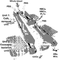
- FIG. 6 is a perspective schematic diagram of the illustrative integrated acoustofluidic separation structure that may advantageously be employed to separate exosomes including a cell-removal unit and an exosome-isolation unit cascaded on a single chip according to aspects of the present disclosure
- FIG. 7 is a photoillustration of an illustrative, integrated acoustofluidic structure including multiple separation structures such as that shown in FIG. 6 according to aspects of the present disclosure.
- FIG. 8 is a schematic diagram of a top view of an acoustofluidic structure illustrating size-based separation occurring in each separation structure (module) due to lateral deflection induced by a tilted-angle standing acoustic field wherein periodic distribution of pressure nodes and antinodes generates an acoustic radiation force to push large particles towards node planes according to aspects of the present disclosure.
- FIGs comprising the drawing are not drawn to scale.
- One such technique employs standing surface acoustic wave(s) (SSAW) to manipulate particulate and/or cellular-scale objects. More particularly, standing SAW-induced acoustic radiation forces are used to change the physical location/orientation of the objects such that separation/sorting results.
- SSAW standing surface acoustic wave
- standing SAW-induced acoustic radiation forces are used to change the physical location/orientation of the objects such that separation/sorting results.
- such techniques and systems constructed therefrom may be conveniently integrated with other devices employed in the biological, chemical, and physical sciences to perform versatile, low power, non-contact, non-invasive separation/sorting.
- FIG. 1(A) is a top-view, schematic diagram of a prior art arrangement for particle separation using standing surface acoustic wave (SSAW)-induced acoustophoresis in a microfluidic channel 130 .
- SSAW standing surface acoustic wave
- the microfluidic channel is shown integrated onto a single chip 110 which also includes a pair of interdigitated transducers 120 that are positioned on either side of the channel substantially along its entire length.
- the generalized structure shown provides continuous particle separation through the effect of standing surface acoustic wave (SSAW)-induced acoustophoresis in the microfluidic channel.
- SSAW standing surface acoustic wave
- particles 150 in a continuous laminar flow are separated based on their volume, density and compressibility.
- a mixture of particles is injected into a microchannel through two side inlets 141 , 142 , sandwiching a deionized water sheath flow injected through a central inlet 140 .
- a one-dimensional SSAW generated by the two parallel interdigital transducers (IDTs) is established across the channel, with the channel spanning a single SSAW pressure node located at the channel center—depicted by region 130 - 2 .
- Application of the SSAW induces larger axial acoustic forces on the particles of larger volume, repositioning them closer to the wave pressure node at the center of the channel.
- the particles are laterally moved to different regions of the channel cross-section based on the particle volume.
- the particles injected into the two side inlets are gradually repositioned to a substantially central, axial region of the channel, and subsequently output port 160 .
- particle separation method is simple and versatile, capable of separating virtually all kinds of particles (regardless of charge/polarization or optical properties) with high separation efficiency and low power consumption.
- FIG. 1(B) is a schematic diagram of a cross-section of a microfluidic channel illustrating how SSAWs may be used to redirect particles undergoing separate particle flow into a unified sheath flow in a microfluidic channel structure.
- SSAWs may be used to redirect particles undergoing separate particle flow into a unified sheath flow in a microfluidic channel structure.
- left side particles undergoing flow in the microfluidic channel experience SSAW forces acting on the particles.
- the SSAW forces acting on the particles induce a central migration of the particles—toward the pressure node of the SSAW.
- the SSAW effect is cumulative and the particles may migrate into a “sheath” flow shown in the figure as being substantially centrally, axially located within the sheath of the overall laminar flow within the microfluidic channel.
- such particle re-directing by an SSAW does not have to be centrally directed and may be directed to one side or another of the channel—as desired by application requirements.
- FIG. 2 is a schematic diagram top-view of an illustrative improved microfluidic channel employing tilted angle standing surface acoustic waves (taSSAW) to redirect particles undergoing particle flow in the channel according to aspects of the present disclosure.
- FIG. 3 is a photo-illustration of a microfluidic channel separation device of FIG. 2 employing ttSSAW according to aspects of the present disclosure.
- taSSAW tilted angle standing surface acoustic waves
- the structure shown therein generally includes a microfluidic channel having three inlet ports (one central sample port and two sheath flow ports—one on each side of the sample port)—and two outlet ports at an opposite end of the channel.
- the overall channel structure(s) may be formed on a single, integrated substrate.
- a channel divider structure positioned between the sample port and one of the sheath ports.
- the length of the micro channel is defined by several regions including a hydrodynamic and SAW focusing region and a PDMS/glass hybrid channel resonator region.
- sample particles in this illustrative example, larger, circulating tumor cells and smaller white blood cells—are injected into the central sample port while fluids are concurrently injected into the sheath flow ports.
- Cells are focused along the divider and in the hybrid PDMS-glass channel resonating region circulating tumor cells (larger particles) and white blood cells (smaller particles) are separated due to the difference(s) in lateral shift.
- the particles are separated such that the white blood cells are directed to one of the two output ports (the upper one in this illustrative figure) while the circulating tumor cells are directed to the other output port (the lower one in this illustrative figure).
- the improved structure shown schematically in FIG. 2 advantageously exhibits an improved throughput over prior art acoustic separation methods/structures by about seven-fold wile exhibiting a high-throughput that can process approximately 7.5 mL of a cell solution within an hour.
- the structures according to the present disclosure employ tilted angle standing acoustic waves (taSSAW)—which result in the diagonal pressure nodes shown in the figure.
- the device is advantageously constructed including a polydimethylsiloxane (PDMS) glass-hybrid channel to form an acoustic enclosure. Accordingly, acoustic wave(s) generated by piezoelectric substrate structures reflects into the channel and resonates, thereby increasing the energy density and resulting throughput.
- PDMS polydimethylsiloxane
- the velocity shadow causes a local decrease in particle velocity resulting in improved separation and specificity due to a longer resulting travel time of the particles within the acoustic field.
- the divider structure generates additional boundary layers in the fluid domain. Accordingly, fluid flowing through the overall structure will exhibit an advantageous velocity profile (i.e., “saddle shaped”) while devices without the divider structure exhibit a more parabolic velocity profile.
- the specific velocity profile change increases the lateral shifts of particles in the SAW field, thereby improving separation efficiency.
- the SAW has a prolonged action/effect on the slowed particles and greater lateral shift results.
- the illustrative acoustic separation structure includes the PDMS microfluidic channel bonded to a piezoelectric substrate between a pair of interdigitated transducers (IDTs).
- IDTs interdigitated transducers
- the IDTs when radio frequency voltage signals are applied to the IDTs, the IDTs generate two Rayleigh waves travelling in opposite directions which interfere within the microfluidic channel.
- a standing wave field is formed where periodic wave nodes and antinodes are generated. Cells flowing through these periodic pressure nodes and antinodes are subjected to different acoustic radiation forces, resulting in lateral displacement.
- the acoustic radiation forces are linearly related to the acoustic energy density.
- a PDMS-glass hybrid channel to form an acoustic enclosure.
- a thin glass layer 130 ⁇ m in thickness
- FIG. 4(A) a schematic cross-sectional diagram of the illustrative prior art PDMS microfluidic channel
- FIG. 4(B) a schematic cross-sectional diagram of the illustrative hybrid PDMS-glass microfluidic channel according to aspects of the present disclosure
- FIG. 4(A) By cursory inspection of these figures, it is illustratively shown that the structure of FIG. 4(A) will absorb a considerable amount of acoustic energy thereby reducing the amount of energy available to reorient/sort particles flowing through the microfluidic channel.
- FIG. 4(B) by employing glass—or other suitably hard, acoustic reflective material—applies much more acoustic energy to the particles thereby enhancing the separation effect(s).
- glass has a much larger acoustic impedance ( ⁇ 12 MPa ⁇ s/m) than PDMS (0.98 MPa ⁇ s/m) and water ( ⁇ 1.49 MPa ⁇ s/m).
- a PDMS-glass hybrid channel to form an acoustic enclosure.
- the horizontal displacement of the surface parallel to the piezoelectric substrate which generates the Rayleigh waves is cancelled, and only the vertical displacement component will propagate leaky acoustic waves into the fluid ( FIG. 4(A) ).
- the leaky waves travel in the fluidic domain and encounter the water-PDMS interface.
- the acoustic impedances of the water and PDMS are ⁇ 1.49 MPa ⁇ s/m and 0.98 MPa ⁇ s/m, respectively.
- the reflection coefficient R water-PDMS is calculated as:
- FIG. 4(C) shows plots of a numerical simulation for the PDMS channel and Hybrid channel of acoustic energy density in the channels.
- the simulations illustrate that the hybrid channel exhibits a higher acoustic energy density because of the acoustic enclosure including the glass top surface.
- devices constructed in this manner generate larger acoustic radiation forces on particles as they flow through the microfluidic channel thereby enabling higher separation throughput.
- FIG. 4(D) , FIG. 4(E) , and FIG. 4(F) are plots of a numerical simulation for a modified channel with a divider and its effectiveness at increasing separation efficiency illustrating: FIG. 4(D) top view of the velocity distributions in the conventional channel (top) and modified channel with a divider (bottom) wherein arrows indicate positions of particles flowing in either channel with perimeter regions exhibiting low velocity while central regions exhibiting higher velocities; FIG. 4(E) velocity distribution curves across the channels showing that in the modified channel a low velocity region was created in the center after the PDMS divider and the velocity profiles in planes at 0.5, 1.5, 2.5, and 35 mm, with respect to the flow direction, after the PDMS divider are graphed; and FIG. 4(F) experimental data showing the lateral deflection displacements of particles (CTCs, WBCs) impacted by velocity—wherein a slower velocity increased the displacement;
- FIG. 4(D) shows the ability of the PDMS divider to adjust fluid velocity profiles in the microchannel.
- the velocity profile in the cross section maintains a parabolic distribution: at the channel walls, the velocity of the fluid is zero. The velocity increases towards the center of the channel and reaches a maximum at the center.
- the cell solution was infused from the central inlet so that the cells would be focused in the center of the channel (as indicated by the arrows), where the velocity is maximum.
- a PDMS divider is located in the center of the modified channel creating two additional boundary layers besides those from the channel walls; the downstream flow profile changes accordingly.
- a shadow-like, low-velocity region forms and spans the acoustic field ( FIG. 4(D) ).
- cells are focused near the PDMS divider and their flow is retarded due to viscous forces. The cells continue traveling slowly as they enter the active acoustic region.
- FIG. 4(E) shows the velocity distribution of a straight channel (parabolic curve) compared against the velocity distribution at various positions along the modified channel.
- the fluid velocity is reduced by approximately 60% in the center as compared to that of the straight channel.
- Even 3.5 mm away from the PDMS divider the velocity profile is still reduced by more than 20%.
- the simulation is supported by experimental data, which indicate a significant drop in velocity at the center of the channel.
- the experimental results were obtained by recording particle trajectories and calculating the velocities of 50 individual particles distributed throughout each region.
- the velocity shadow successfully decreased the speed of the cells as they entered the acoustic field zone, enabling more time for the acoustic radiation force to differentiate CTCs from WBCs.
- the resulting lateral displacement induced by acoustic field is thus enhanced when compared to the straight channel design.
- FIG. 4(F) shows a numerical simulation of cell deflection as a function of flow velocity.
- the trajectories of the CTCs and WBCs are simulated under the conditions of 100% and 50% of the maximum velocity in a straight channel. From the trajectories, the decrease in velocity leads to a larger lateral shift and as such, CTCs can be separated from WBCs more efficiently.
- illustrative devices and structures have been fabricated using Y+128° X-propagation lithium niobate (LiNbO 3 ) as piezoelectric substrates.
- the IDT design was patterned by photolithography using a MA/BA6 mask aligner (SUSS MicroTec., Germany). After that, 50 ⁇ of Cr was deposited as an adhesive layer, followed by a 500 ⁇ gold layer for electrode fabrication. The deposition was conducted with an e-beam evaporator (Semicore Corp, USA). Finally, the metal layer was removed with photoresist and IDTs were formed by a lift-off process.
- the PDMS/glass hybrid channel was fabricated by a standard soft lithography process, as shown in FIG. 5 .
- a thin layer of SU8 100 photoresist (MicroChem, USA) was spin-coated and patterned by UV exposure on a silicon wafer.
- a glass slide was placed on the SU8 mold at the designed position where standing acoustic filed was formed.
- the glass slide was made from micro cover glass (VWR, USA), and was cut to 800 ⁇ m ⁇ 5 mm by laser cutting.
- Sylgard 184 Silicone Elastomer Curing Agent and Base was mixed at 1:10 and poured on the mold. After setting at room temperature overnight, the PDMS channel was peeled from the mold and bonded to the LiNbO 3 substrate. Before bonding, the surface of the LiNbO 3 substrate and the PDMS channel was treated with oxygen plasma.
- the high-throughput acoustic separation device was placed on a Peltier cooler (TEC1-12730, Hebei I.T., China) which served as a heat sink.
- the voltage for the cooler was ⁇ 2V.
- the device and cooler were placed on the stage of an upright microscope (BX51WI, Olympus, Japan) during the separation experiment.
- the fluid flows, including sheath fluid and sample fluid, were controlled by individual syringe pumps (neMESYS, cetoni GmbH, Germany).
- ethanol was flushed through the whole microfluidic device to remove air bubbles from the channel, followed by PBS washing for 3 min.
- the channel was filled with 1% bovine serum albumin (Sigma-Aldrich, USA) solution and left for 5 min to coat the channel surface.
- the sample mixture was then introduced to the device at a flow rate of 125 ⁇ L/min.
- the flow rates for two sheath fluids were 110 ⁇ L/min and 220 ⁇ L/min.
- Cells from the device outlets were collected either in a 35 ⁇ 10 mm Petri dish (Corning) or 1.7 mL Eppendorf centrifuge tubes.
- the acoustic wave was excited by applying a radio frequency (RF) signal to the IDTs on the piezoelectric substrate.
- RF radio frequency
- the RF signal was generated by a function generator (E4422B; Agilent, USA) and an amplifier (25A100A; Amplifier Research, USA).
- the frequency was set at 19.9 MHz, and the power inputs ranged from 32 to 35 dBm.
- the separation devices to isolate PC-3, LnCaP, HeLa, and MCF-7 cancer cells, which represent a range of hormone-sensitive prostate cancer cells, castration-resistant prostate cancer cells, cervical cancer cultured cell lines, and breast cancer cultured cell lines, respectively.
- WBCs were collected from 1 mL of blood from healthy volunteers and then re-suspended with cancer cells stained with Calcein-AM in PBS. In order to improve visualization of the separation process, a large number of cancer cells are mixed with this suspension. The ratio of cancer cells to WBCs varied from 1:5 to 1:10. Cell separation at the outlet region was recorded under fluorescent microscopes.
- the rare cell population was simulated by incorporating 50 to 1,000 Calcein-AM-stained cancer cells into 1 mL of WBCs.
- the concentration of WBCs ranged from 3 to 6 million cells per mL.
- This mixture was processed through the acoustic separation device at a flow rate of 7.5 mL/h. Cells were gathered from both the collection and waste outlets. The fluorescent cancer cells were counted at both outlets, and the recovery rate was calculated by dividing the number of cancer cells in the collection outlet by the total number cancer cells from both outlets. An average recovery rate greater than 86% is obtained for all these samples.
- CTC separation After demonstrating cancer cell separation with blood samples that contained pre-determined proportions of cancer cells from cultures, we performed CTC separation using blood samples that were collected from patients with prostate cancer. Men with castration-resistant metastatic prostate cancer and widespread bone metastases were enrolled as part of an IRB-approved clinical protocol at Duke University under informed consent, and blood samples were collected for CTC isolation. All men were receiving radium-223 therapy as part of their standard therapy, and all had received prior hormonal therapies for metastatic prostate cancer. Immunostaining of cytokeratin 8, 18(CK8, 18) and pan-leukocyte marker CD45 as well as nucleus staining of DAPI were used to identify the cells. CTCs were identified as CK8,18+/CD45 ⁇ /DAPI+; DAPI ⁇ was regarded as debris or dust; cells were otherwise identified as WBCs.
- CTCs Based on immunostaining criteria, we have identified CTCs from five clinical blood samples, with counts ranging from 0.93 to 400 CTCs per mL.
- PSMA which is a transmembrane protein that has considerable overexpression on most prostate cancer cells, and thus is used as a diagnostic imaging target and has emerged as a potential therapeutic target.
- PSMA expression in CTCs It is notable that although the majority of prostate cancer CTCs had PSMA overexpression, a fraction of the CTCs expressed relatively low levels of PSMA. Loss of PSMA positivity in the CTCs from prostate cancer patients could be a reflection of tumor heterogeneity and suppression of androgen receptor activity during castration-resistant progression. This result also indicates that PSMA-targeted imaging and directed therapies could miss some of the tumor cells and therefore be ineffective.
- the diameters of 70 CTCs and 64 WBCs were measured and are plotted in FIG. 6B .
- the diameter of CTCs has a median diameter of 16.5 ⁇ m with a 95% confidence interval at 0.61 ⁇ m.
- 50% of the CTCs ranged from 14.5 to 18 ⁇ m.
- the WBCs' diameters were 11.8 ⁇ 0.54 ⁇ m; 50% of the WBCs were within 10.5-14 ⁇ m diameter.
- the size distribution of WBCs and CTCs present P values less than 0.0001. However, it is noteworthy that the size distributions of CTCs and WBCs overlapped.
- CTC clusters may be of greater relevance than single CTCs for improving our understating of the mechanisms of metastasis. Further studies on clustered CTCs could be valuable to identifying CTC subgroups and CTC cells, and may reveal important information about the metastatic process.
- the immunostaining identified some cells with both cytokeratin and leukocyte markers, namely CK8,18+ and CD45+.
- these “double-positive” cells are typically excluded from CTC enumeration, they might be inherently related to CTCs. In addition, these double-positive cells are observed rarely in healthy donors' blood samples. The identity of these double-positive cells is currently not well understood.
- These CTCs may be “disguised” upon ingestion of leukocyte-derived proteins, while some monocytes may be coated with tumor-derived markers. To address this situation, further studies such as using other specific markers need to be performed with our acoustic separation platform. Our study shows that the double-positive cells are present in two categories: clusters with other CTCs and as individual cells. The presence of cell clusters with CTCs and dual-positive cells suggests that cell-to-cell interactions are a possible mechanism for the formation of these dual-positive cells.
- a two-module separator structure that may advantageously be integrated onto a single substrate—that can sequentially separate blood cells from EVs, and then further differentiate the subtypes of EVs.
- the acoustofluidic separation structure includes a cell-removal module and an exosome-isolation module.
- the cell-removal module is designed to first fractionate blood components larger than 1 ⁇ m, including red blood cells (RBCs), white blood cells (WBCs), and platelets.
- the exosome-isolation module which may be configured (optimized) to separate nanoscale bioparticles.
- the exosome-isolation module enables the discrimination of submicron particles, such that subgroups of EVs with larger size (including microvesicles (MVs) and apoptotic bodies (ABs)) are separated from EVs, thereby preserving the exosomes.
- MVs microvesicles
- ABs apoptotic bodies
- the device illustrated therein includes an elongated channel structure having three input ports at one end, a pair of outlet port at an opposite end, and an intermediate (waste) input/output port formed on one side. Shown further is a cell removal unit/region including a pair of IDTs and a “downstream”, exome-isolation/separation unit/region including an additional pair of IDTs. Note that the intermediate (waste) input/output port formed in a side wall of the channel is positioned between the cell-removal region and the exome-isolation region.
- whole blood is introduced at the central input port while two phosphate-buffered saline (PBS) sheath flows are introduced into the two ports on either side of the central port.
- PBS phosphate-buffered saline
- Particles comprising the whole blood are redirected during flow through the channel by tilted-angle standing acoustic field generated by the IDTs comprising the cell removal unit and—later in flow—the exome-isolation unit. Note that as the particles undergo the effects of the cell removal unit, particular large cells including the RBCs, WBCs, and PLTs are redirected to the side-formed waste port.
- Additional PBS is injected into an input portion of the waste port and particles remaining in the flow are further redirected through the effects of the exosome-isolation unit which further separates the EXOs from the ABs and MVs, which in turn are directed to separate output ports as shown.
- the periodic distribution of pressure nodes and antinodes generates an acoustic radiation force to push large particles towards node planes.
- FIG. 7 is a photoillustration of an illustrative, integrated acoustofluidic structure including multiple separation structures such as that shown in FIG. 6 according to aspects of the present disclosure.
- the integrated acoustofluidic separation device shown therein illustratively includes a lithium niobate (LiNbO 3 ) substrate, two pairs of IDTs, and a polydimethylsiloxane (PDMS) microchannel.
- the two IDTs are deposited on the LiNbO 3 substrate using photolithography and liftoff processes, and their driving frequencies are designed as ⁇ 20 MHz and ⁇ 40 MHz, respectively.
- the PDMS microchannel is bonded onto the LiNbO 3 substrate in between the IDTs.
- the channel includes the following ports: a sample inlet for whole blood, three inlets for buffer solution as sheath flows, an outlet for blood cells (Waste), an outlet for subgroups of EVs other than exosomes, and an outlet for purified exosomes.
- a pre-filtration unit in which PDMS pillar arrays were constructed, is placed in the blood sample inlet to prevent the blood cells from aggregating.
- the microchannel is aligned to form specific angles with respect to IDTs. Based on our numerical and experimental investigations, the optimal angles between the channel and IDTs are 5° and 15° for the cell-removal module and the exosome-isolation module, respectively.
- FIG. 8 is a schematic diagram of a top view of an acoustofluidic structure illustrating size-based separation occurring in each separation structure (module) due to lateral deflection induced by a tilted-angle standing acoustic field wherein periodic distribution of pressure nodes and antinodes generates an acoustic radiation force to push large particles towards node planes according to aspects of the present disclosure.
- Equation (2) is the expression for the acoustic contrast factor ⁇ , which determines whether the particle moves towards pressure nodes or antinodes in the SAW field. For cells and vesicles, the acoustic contrast factor is positive, which means that they will move towards pressure nodes.
- Drag force is proportional to the radius of the particles or cells and the acoustic radiation force is proportional to the volume.
- the acoustic radiation force dominates over the drag force for larger particles, which causes the particle stream to translate towards the tilted nodes.
- the drag force cancels a significant part of acoustic radiation force out for smaller particles, resulting in little lateral displacement.
- particles are therefore directed to different outlets.
- our acoustofluidic-based separation strategy is capable of increasing or decreasing the cutoff diameter. This feature gives our device the flexibility to be used for a wide variety of applications.
- NTA nanoparticle tracking analysis
- DLS dynamic light scattering
- the original mixture of purified microvesicles and exosomes had a board size distribution from ⁇ 50 nm to 600 nm; specifically, there was a single peak at 122 nm, which was referred to be exosomes, whereas other peaks appeared between 170 nm and 300 nm represented the broader distribution of microvesicles compared to exosomes. Additionally, the concentration distribution curve reached a valley at 140 nm, which was therefore chosen as the cut-off size for separation.
- the sample at the collection outlet exhibited only one peak between ⁇ 50 nm to 100 nm, and the peak position presented a modest shift from 122 nm to 99 nm, which may be caused by resolution limits of NTA when testing highly heterogeneous samples.
- the sample collected from the waste outlet by contrast, exhibited several peaks larger than 170 nm along with very few components that were less than 100 nm.
- the concentrations of particles collected from the exosome outlets were 8.42 ⁇ 10 7 ( ⁇ 140 nm) and 1.4 ⁇ 10 6 (>140 nm), respectively.
- the concentrations of particles collected from the microvesicle outlets were 1.8 ⁇ 10 7 ( ⁇ 140 nm) and 3.35 ⁇ 10 8 particles (>140 nm).
- the total numbers of vesicles before and after separation were 4.37 ⁇ 10 8 and 4.386 ⁇ 10 8 , respectively.
- the percentages of small particles and larger particles were comparable before (23.6%) and after separation (23.3%), suggesting that the acoustofluidic separation technique has a high yield and does not lose much samples during the separation process.
- the acoustofluidic-based exosome-isolation device shows excellent performance in terms of separating vesicle samples based on size difference; a purity of 98.4% was achieved for the particles smaller than 140 nm collected from the exosome outlet, and 82.4% of the small particles were directed to the exosome outlet.
- the cell-removal module and exosome-isolation module into a single acoustofluidic chip.
- the flow rates of each inlet were set to 4 ⁇ l/min for the blood sample, 4 ⁇ l/min and 12 ⁇ l/min for sheath flows in the cell-removal unit, and 10 ⁇ l/min for sheath flow in the exosome-isolation unit.
- the driving frequency and voltage of the input RF signal for the integrated device were the same as those used for individual units. When the acoustic field was off, the blood stream was focused in the middle of channel and is directed into the outlet F.
- the RF signal When the RF signal was on for both modules, blood components were separated toward different outlets.
- the exosome-isolation module once activated, directs the apoptotic bodies, microvesicles, and the remaining part of cells to the outlet G, referred to as the vesicle-waste outlet, thereby isolating exosomes from whole blood samples.
- the concentration of cells was 2.08 ⁇ 10 4 cells per milliliter in the sample collected from the exosome outlet, while the RBC count reference ranged from 4.7 to 6.1 ⁇ 10 10 cells per milliliter, yielding a cell removal rate over 99.999%.
- the sample collected from the exosome outlet showed a clear, narrow peak at around 100 nm, which corresponded to exosomes, while the control group displayed a flat, disperse curve covering a broad range from ⁇ 50 nm to 1 ⁇ m.
- the NTA results demonstrate that the acoustofluidic-based separation device differentiated subgroups of EVs based on size, and thereby isolated exosomes from the mixture.
Landscapes
- Chemical & Material Sciences (AREA)
- Health & Medical Sciences (AREA)
- Life Sciences & Earth Sciences (AREA)
- General Health & Medical Sciences (AREA)
- Physics & Mathematics (AREA)
- Analytical Chemistry (AREA)
- Engineering & Computer Science (AREA)
- Biochemistry (AREA)
- Organic Chemistry (AREA)
- Bioinformatics & Cheminformatics (AREA)
- Wood Science & Technology (AREA)
- Zoology (AREA)
- Genetics & Genomics (AREA)
- Clinical Laboratory Science (AREA)
- Chemical Kinetics & Catalysis (AREA)
- Molecular Biology (AREA)
- Dispersion Chemistry (AREA)
- Pathology (AREA)
- Hematology (AREA)
- Immunology (AREA)
- General Physics & Mathematics (AREA)
- Acoustics & Sound (AREA)
- General Engineering & Computer Science (AREA)
- Microbiology (AREA)
- Biotechnology (AREA)
- Biomedical Technology (AREA)
- Mechanical Engineering (AREA)
- Physical Or Chemical Processes And Apparatus (AREA)
Abstract
Description
F d=−6πηR p(u p −u f) [3]
where η, Rp, up, and uf are the viscosity of the fluid, radius of the particle, velocity of the particle, and velocity of the fluid, respectively.
Claims (7)
Priority Applications (1)
| Application Number | Priority Date | Filing Date | Title |
|---|---|---|---|
| US16/642,641 US11491486B2 (en) | 2017-08-29 | 2018-08-29 | Systems, methods, and structures for surface acoustic wave-based separation |
Applications Claiming Priority (3)
| Application Number | Priority Date | Filing Date | Title |
|---|---|---|---|
| US201762551270P | 2017-08-29 | 2017-08-29 | |
| US16/642,641 US11491486B2 (en) | 2017-08-29 | 2018-08-29 | Systems, methods, and structures for surface acoustic wave-based separation |
| PCT/US2018/048629 WO2019046483A1 (en) | 2017-08-29 | 2018-08-29 | Systems, methods, and structures for surface acoustic wave-based separation |
Publications (2)
| Publication Number | Publication Date |
|---|---|
| US20210154668A1 US20210154668A1 (en) | 2021-05-27 |
| US11491486B2 true US11491486B2 (en) | 2022-11-08 |
Family
ID=65526010
Family Applications (1)
| Application Number | Title | Priority Date | Filing Date |
|---|---|---|---|
| US16/642,641 Active 2039-04-20 US11491486B2 (en) | 2017-08-29 | 2018-08-29 | Systems, methods, and structures for surface acoustic wave-based separation |
Country Status (2)
| Country | Link |
|---|---|
| US (1) | US11491486B2 (en) |
| WO (1) | WO2019046483A1 (en) |
Families Citing this family (8)
| Publication number | Priority date | Publication date | Assignee | Title |
|---|---|---|---|---|
| EP3610265A1 (en) * | 2017-04-14 | 2020-02-19 | Ventana Medical Systems, Inc. | Size-based separation of dissociated fixed tissues |
| US11577241B2 (en) | 2018-12-03 | 2023-02-14 | Duke University | Acoustofluidic systems including acoustic wave generators for manipulating fluids, droplets, and micro/nano objects within a fluid suspension and related methods |
| GB201904601D0 (en) * | 2019-04-02 | 2019-05-15 | Univ College Cardiff Consultants Ltd | Acoustofluidic device |
| CN112076808B (en) * | 2019-06-13 | 2024-06-28 | 安行生物技术有限公司 | Method and apparatus for controlling movement of particles in solution using ultra-high frequency sound waves |
| CN113680405A (en) * | 2021-08-26 | 2021-11-23 | 哈尔滨工业大学 | Method for controlling moving speed and direction of micro-droplets driven by surface acoustic waves |
| WO2023142511A1 (en) * | 2022-01-28 | 2023-08-03 | The Hong Kong Research Institute Of Textiles And Apparel Limited | Filter-free, sweeping acoustic wave separation apparatus for separating micro-sized materials from a fluid |
| CN116656489B (en) * | 2023-07-28 | 2023-10-27 | 中南大学 | A standing wave acoustic fluidic device for sorting exosomes in body fluids and its use method |
| CN118744017A (en) * | 2024-06-18 | 2024-10-08 | 中南大学 | Glass embedded detachable surface wave acoustic fluidic sorting chip and manufacturing method thereof |
Citations (6)
| Publication number | Priority date | Publication date | Assignee | Title |
|---|---|---|---|---|
| US20030150806A1 (en) | 2002-02-13 | 2003-08-14 | Nanostream, Inc. | Separation column devices and fabrication methods |
| US20100139377A1 (en) | 2008-12-05 | 2010-06-10 | The Penn State Reserch Foundation | Particle focusing within a microfluidic device using surface acoustic waves |
| US20110154890A1 (en) | 2008-10-08 | 2011-06-30 | Foss Analytical A/S | Separation of particles in liquids by use of a standing ultrasonic wave |
| US20140033808A1 (en) * | 2012-08-01 | 2014-02-06 | The Penn State Research Foundation | High-efficiency separation and manipulation of particles and cells in microfluidic device using surface acoustic waves at an oblique angle |
| WO2016025518A1 (en) | 2014-08-11 | 2016-02-18 | Carnegie Mellon University | Separation of low-abundance cells from fluid using surface acoustic waves |
| US20160139012A1 (en) * | 2013-03-15 | 2016-05-19 | The Trustees Of Princeton University | Methods and devices for high throughput purification |
-
2018
- 2018-08-29 US US16/642,641 patent/US11491486B2/en active Active
- 2018-08-29 WO PCT/US2018/048629 patent/WO2019046483A1/en active Application Filing
Patent Citations (6)
| Publication number | Priority date | Publication date | Assignee | Title |
|---|---|---|---|---|
| US20030150806A1 (en) | 2002-02-13 | 2003-08-14 | Nanostream, Inc. | Separation column devices and fabrication methods |
| US20110154890A1 (en) | 2008-10-08 | 2011-06-30 | Foss Analytical A/S | Separation of particles in liquids by use of a standing ultrasonic wave |
| US20100139377A1 (en) | 2008-12-05 | 2010-06-10 | The Penn State Reserch Foundation | Particle focusing within a microfluidic device using surface acoustic waves |
| US20140033808A1 (en) * | 2012-08-01 | 2014-02-06 | The Penn State Research Foundation | High-efficiency separation and manipulation of particles and cells in microfluidic device using surface acoustic waves at an oblique angle |
| US20160139012A1 (en) * | 2013-03-15 | 2016-05-19 | The Trustees Of Princeton University | Methods and devices for high throughput purification |
| WO2016025518A1 (en) | 2014-08-11 | 2016-02-18 | Carnegie Mellon University | Separation of low-abundance cells from fluid using surface acoustic waves |
Non-Patent Citations (2)
| Title |
|---|
| Authorized Officer: Blaine R. Copenheaver, International Search Report and Written Opinion issued in counterpart PCT application No. PCT/US2018/048629, dated Dec. 27, 2018, 12 pp. |
| Lee et al., Acoustic Purification of Extracellular Microvesicles, 2015, ACS Nano., 9(3), p. 1-14 (or p. 2321-2327). (Year: 2015). * |
Also Published As
| Publication number | Publication date |
|---|---|
| WO2019046483A1 (en) | 2019-03-07 |
| US20210154668A1 (en) | 2021-05-27 |
Similar Documents
| Publication | Publication Date | Title |
|---|---|---|
| US11491486B2 (en) | Systems, methods, and structures for surface acoustic wave-based separation | |
| US11944971B2 (en) | Sorting particles in a microfluidic device | |
| US20200122146A1 (en) | Platelet-Targeted Microfluidic Isolation of Cells | |
| US9606086B2 (en) | High-efficiency separation and manipulation of particles and cells in microfluidic device using surface acoustic waves at an oblique angle | |
| Moon et al. | Continuous separation of breast cancer cells from blood samples using multi-orifice flow fractionation (MOFF) and dielectrophoresis (DEP) | |
| US9556485B2 (en) | Methods and compositions for detecting non-hematopoietic cells from a blood sample | |
| US10035104B2 (en) | Biochip for high-throughput screening of circulating tumor cells | |
| US8986944B2 (en) | Methods and compositions for separating rare cells from fluid samples | |
| Geislinger et al. | Sorting of circulating tumor cells (MV3-melanoma) and red blood cells using non-inertial lift | |
| US20140008210A1 (en) | Methods and compositions for separating or enriching cells | |
| JP2014528089A (en) | System and method for separating cells and / or particles | |
| Talebjedi | Developing an acoustic-based microfluidics micro/nano scale particle separation and manipulation platform with application for extracellular vesicle isolation | |
| Sen et al. | Microfluidics device for isolation of circulating tumor cells in blood | |
| Al Ali | A Hybrid Microfluidic Device for Label Free Manipulation and Size-Independent Separation of Microentities | |
| Wu | Acoustofluidic separation technology for advancing health care | |
| Sen et al. | 5 Microfluidics Device for Isolation of Circulating Tumor Cells in Blood | |
| Wu et al. | Chuyi et al. 2018. Circulating Tumor Cell Phenotyping via High# Throughput Acoustic Separation." |
Legal Events
| Date | Code | Title | Description |
|---|---|---|---|
| AS | Assignment |
Owner name: DUKE UNIVERSITY, NORTH CAROLINA Free format text: ASSIGNMENT OF ASSIGNORS INTEREST;ASSIGNORS:HUANG, JUN;WU, MENGXI;SIGNING DATES FROM 20180126 TO 20180302;REEL/FRAME:051953/0091 |
|
| FEPP | Fee payment procedure |
Free format text: ENTITY STATUS SET TO UNDISCOUNTED (ORIGINAL EVENT CODE: BIG.); ENTITY STATUS OF PATENT OWNER: SMALL ENTITY |
|
| FEPP | Fee payment procedure |
Free format text: ENTITY STATUS SET TO SMALL (ORIGINAL EVENT CODE: SMAL); ENTITY STATUS OF PATENT OWNER: SMALL ENTITY |
|
| STPP | Information on status: patent application and granting procedure in general |
Free format text: APPLICATION DISPATCHED FROM PREEXAM, NOT YET DOCKETED |
|
| STPP | Information on status: patent application and granting procedure in general |
Free format text: DOCKETED NEW CASE - READY FOR EXAMINATION |
|
| STPP | Information on status: patent application and granting procedure in general |
Free format text: NON FINAL ACTION MAILED |
|
| STPP | Information on status: patent application and granting procedure in general |
Free format text: RESPONSE TO NON-FINAL OFFICE ACTION ENTERED AND FORWARDED TO EXAMINER |
|
| STPP | Information on status: patent application and granting procedure in general |
Free format text: FINAL REJECTION MAILED |
|
| STPP | Information on status: patent application and granting procedure in general |
Free format text: NOTICE OF ALLOWANCE MAILED -- APPLICATION RECEIVED IN OFFICE OF PUBLICATIONS |
|
| STPP | Information on status: patent application and granting procedure in general |
Free format text: PUBLICATIONS -- ISSUE FEE PAYMENT RECEIVED |
|
| STPP | Information on status: patent application and granting procedure in general |
Free format text: PUBLICATIONS -- ISSUE FEE PAYMENT VERIFIED |
|
| STCF | Information on status: patent grant |
Free format text: PATENTED CASE |