US11453093B2 - Reciprocating tool having planetary gear assembly and counterweighting assembly - Google Patents
Reciprocating tool having planetary gear assembly and counterweighting assembly Download PDFInfo
- Publication number
- US11453093B2 US11453093B2 US16/450,538 US201916450538A US11453093B2 US 11453093 B2 US11453093 B2 US 11453093B2 US 201916450538 A US201916450538 A US 201916450538A US 11453093 B2 US11453093 B2 US 11453093B2
- Authority
- US
- United States
- Prior art keywords
- reciprocating
- pin
- tool
- reciprocating mechanism
- coupled
- Prior art date
- Legal status (The legal status is an assumption and is not a legal conclusion. Google has not performed a legal analysis and makes no representation as to the accuracy of the status listed.)
- Active, expires
Links
Images


Classifications
-
- B—PERFORMING OPERATIONS; TRANSPORTING
- B23—MACHINE TOOLS; METAL-WORKING NOT OTHERWISE PROVIDED FOR
- B23Q—DETAILS, COMPONENTS, OR ACCESSORIES FOR MACHINE TOOLS, e.g. ARRANGEMENTS FOR COPYING OR CONTROLLING; MACHINE TOOLS IN GENERAL CHARACTERISED BY THE CONSTRUCTION OF PARTICULAR DETAILS OR COMPONENTS; COMBINATIONS OR ASSOCIATIONS OF METAL-WORKING MACHINES, NOT DIRECTED TO A PARTICULAR RESULT
- B23Q5/00—Driving or feeding mechanisms; Control arrangements therefor
- B23Q5/02—Driving main working members
- B23Q5/027—Driving main working members reciprocating members
-
- B—PERFORMING OPERATIONS; TRANSPORTING
- B23—MACHINE TOOLS; METAL-WORKING NOT OTHERWISE PROVIDED FOR
- B23D—PLANING; SLOTTING; SHEARING; BROACHING; SAWING; FILING; SCRAPING; LIKE OPERATIONS FOR WORKING METAL BY REMOVING MATERIAL, NOT OTHERWISE PROVIDED FOR
- B23D51/00—Sawing machines or sawing devices working with straight blades, characterised only by constructional features of particular parts; Carrying or attaching means for tools, covered by this subclass, which are connected to a carrier at both ends
- B23D51/16—Sawing machines or sawing devices working with straight blades, characterised only by constructional features of particular parts; Carrying or attaching means for tools, covered by this subclass, which are connected to a carrier at both ends of drives or feed mechanisms for straight tools, e.g. saw blades, or bows
-
- F—MECHANICAL ENGINEERING; LIGHTING; HEATING; WEAPONS; BLASTING
- F16—ENGINEERING ELEMENTS AND UNITS; GENERAL MEASURES FOR PRODUCING AND MAINTAINING EFFECTIVE FUNCTIONING OF MACHINES OR INSTALLATIONS; THERMAL INSULATION IN GENERAL
- F16F—SPRINGS; SHOCK-ABSORBERS; MEANS FOR DAMPING VIBRATION
- F16F15/00—Suppression of vibrations in systems; Means or arrangements for avoiding or reducing out-of-balance forces, e.g. due to motion
- F16F15/28—Counterweights, i.e. additional weights counterbalancing inertia forces induced by the reciprocating movement of masses in the system, e.g. of pistons attached to an engine crankshaft; Attaching or mounting same
-
- F—MECHANICAL ENGINEERING; LIGHTING; HEATING; WEAPONS; BLASTING
- F16—ENGINEERING ELEMENTS AND UNITS; GENERAL MEASURES FOR PRODUCING AND MAINTAINING EFFECTIVE FUNCTIONING OF MACHINES OR INSTALLATIONS; THERMAL INSULATION IN GENERAL
- F16H—GEARING
- F16H1/00—Toothed gearings for conveying rotary motion
- F16H1/28—Toothed gearings for conveying rotary motion with gears having orbital motion
-
- F—MECHANICAL ENGINEERING; LIGHTING; HEATING; WEAPONS; BLASTING
- F16—ENGINEERING ELEMENTS AND UNITS; GENERAL MEASURES FOR PRODUCING AND MAINTAINING EFFECTIVE FUNCTIONING OF MACHINES OR INSTALLATIONS; THERMAL INSULATION IN GENERAL
- F16H—GEARING
- F16H21/00—Gearings comprising primarily only links or levers, with or without slides
- F16H21/10—Gearings comprising primarily only links or levers, with or without slides all movement being in, or parallel to, a single plane
- F16H21/16—Gearings comprising primarily only links or levers, with or without slides all movement being in, or parallel to, a single plane for interconverting rotary motion and reciprocating motion
- F16H21/18—Crank gearings; Eccentric gearings
- F16H21/36—Crank gearings; Eccentric gearings without swinging connecting-rod, e.g. with epicyclic parallel motion, slot-and-crank motion
-
- F—MECHANICAL ENGINEERING; LIGHTING; HEATING; WEAPONS; BLASTING
- F16—ENGINEERING ELEMENTS AND UNITS; GENERAL MEASURES FOR PRODUCING AND MAINTAINING EFFECTIVE FUNCTIONING OF MACHINES OR INSTALLATIONS; THERMAL INSULATION IN GENERAL
- F16H—GEARING
- F16H37/00—Combinations of mechanical gearings, not provided for in groups F16H1/00 - F16H35/00
- F16H37/12—Gearings comprising primarily toothed or friction gearing, links or levers, and cams, or members of at least two of these types
- F16H37/124—Gearings comprising primarily toothed or friction gearing, links or levers, and cams, or members of at least two of these types for interconverting rotary motion and reciprocating motion
Definitions
- This document relates, generally, to a reciprocating mechanism for a power tool, and in particular to a reciprocating mechanism with a counterbalancing mechanism for a reciprocating power tool
- Reciprocating mechanisms may be included in various different types of tools, for example, reciprocating saws and jig saws, to convert rotary force, or motion, to linear force, or motion, and/or to convert linear force/motion to rotary force/motion, for output by the tool.
- Operation of a motor of this type of power tool may generate a force, for example, a rotational force.
- a reciprocating mechanism may convert the rotational force, or rotational motion, output by the motor to a linear force, or linear motion, to drive a reciprocal motion of an output spindle of the tool.
- the reciprocating mechanism may be coupled to the motor by, for example, a transmission mechanism that provides for force transfer between the motor and the reciprocating mechanism.
- Vibration generated due to operation of the motor and the reciprocating mechanism may adversely affect operation of the tool, and may produce user fatigue.
- Providing for balance in the reciprocating mechanism may improve user control of the tool, and may enhance utility and operational safety, enabling a user to operate the tool for extended periods of time, versus a limited duration, for a tool which may otherwise have relatively high vibration during operation.
- a relatively compact tool profile may improve user control of the tool, and may allow the user to access smaller, tighter spaces using the tool.
- a power-driven reciprocating tool may include a motor, a reciprocating mechanism, and a planetary gear assembly coupled between the motor and the reciprocating mechanism.
- the planetary gear assembly may convert a rotational force generated by the motor to a linear force output by the reciprocating mechanism.
- the planetary gear assembly may include a gear carrier, a sun gear received in the gear carrier, and coupled to an output shaft of the motor so as to receive a rotational force from the motor, at least one planet gear coupled in the gear carrier, and in meshed engagement with the sun gear, such that the carrier rotates in response to the rotational force received from the motor, and a pin fixed to and extending outward from a lower portion of the gear carrier such that the pin rotates together with the gear carrier, wherein the pin is coupled to the reciprocating mechanism.
- the reciprocating mechanism may be configured to reciprocate linearly in response to rotation of the pin.
- the tool may also include a counterbalancing mechanism coupled to the pin.
- the counterbalancing mechanism may be configured to reciprocate linearly in response to rotation of the pin, in a direction that is opposite that of the reciprocating mechanism, so as to balance the linear reciprocating movement of the reciprocating mechanism.
- the reciprocating mechanism may include a reciprocating shaft having a yoke at an end portion thereof. The pin may extend through an elongated slot in the yoke so as to couple the planetary gear assembly and the reciprocating mechanism to a counterbalancing mechanism.
- the counterbalancing mechanism may include an eccentric member having an opening therein in which the pin is coupled, a counterbalance member, and a shaft extending from the eccentric member into an elongated slot in the counterbalance member so as to movably couple the counterbalance member to the eccentric member.
- the pin is configured to move linearly in the elongated slot in the yoke in response to rotation of the gear carrier and the pin received in the elongated slot
- the eccentric member is configured to revolve about the shaft in response to the linear movement of the pin in the slot
- the reciprocating mechanism is configured to reciprocate linearly along a reciprocating axis in response to the linear movement of the pin in the slot
- the counterbalance member is configured to reciprocate linearly along the reciprocating axis, in a direction opposite that of the reciprocating mechanism, in response to the revolving of the eccentric member about the shaft.
- the tool may also include a counterbalance member, and an eccentric member coupled to the reciprocating mechanism and to the counterbalance member.
- the pin may be coupled in an opening formed in the eccentric member so as to couple the planetary gear assembly, the reciprocating mechanism and the counterbalance member.
- a bushing may be movably received in an elongated slot formed in the reciprocating mechanism, wherein the pin extends through the bushing, and into the opening formed in the eccentric member.
- the eccentric member may include a first disc portion wherein the opening in which the pin is received is formed in the first disc portion, and the first disc portion is movably received in an elongated slot formed in the reciprocating mechanism, a second disc portion coupled to the first disc portion such that respective central portions of the first disc portion and the second disc portion are offset, and a shaft extending outward from the second disc portion, and into the counterbalance member so as to couple the eccentric member to the counterbalance member.
- the reciprocating mechanism may be configured to reciprocate linearly in response to rotation of the gear carrier and the pin
- the counterbalance member may be configured to reciprocate linearly, in a direction opposite that of the reciprocating mechanism, in response to the rotation of the gear carrier and the pin.
- the eccentric member may include a first disc portion having the opening formed therein in which the pin is coupled, a second disc portion coupled to, and offset from, the first disc portion, and a shaft extending outward, from the second disc portion, and into the counterbalance member so as to couple the eccentric member to the counterbalance member.
- the pin In response to rotation of the gear carrier and pin coupled thereto, the pin may move linearly, along a first linear axis, in the elongated slot formed in the reciprocating mechanism, the second disc portion of the eccentric member may revolve about the shaft, the reciprocating mechanism may reciprocate along a second linear axis, and the counterbalance member may reciprocate linearly along the second linear axis, in a direction opposite that of the reciprocating mechanism so as to balance the linear reciprocating movement of the reciprocating mechanism.
- the first linear axis may be substantially orthogonal to the second linear axis.
- the tool may also include a first guide plate on a first surface of the counterbalance member to guide the linear reciprocating movement of a yoke portion at a first end portion of the reciprocating mechanism, a second guide plate on a second surface of the counterbalance member to guide the linear reciprocating movement of the counterbalance member, and a bushing at a second end portion of the reciprocating mechanism to guide the linear reciprocating movement of a shaft portion of the reciprocating mechanism.
- a power-driven reciprocating tool may include a motor, a reciprocating mechanism, a transmission mechanism coupled between the motor and the reciprocating mechanism, wherein the transmission mechanism may transmit a driving force generated by the motor to the reciprocating mechanism, and the reciprocating mechanism reciprocates linearly in response to the driving force transmitted thereto by the transmission mechanism, and a counterbalancing mechanism coupled to the transmission mechanism, wherein the counterbalancing mechanism may reciprocate linearly in response to the driving force generated by the motor.
- a linear reciprocating direction of the counterbalancing mechanism may be opposite a linear reciprocating direction of the reciprocating mechanism, so as to balance the linear reciprocating movement of the reciprocating mechanism.
- the counterbalancing mechanism may include a first counterbalance member, and an eccentric member coupled to the transmission mechanism, the reciprocating mechanism, and the counterbalance mechanism.
- the eccentric member may include a first disc portion that is fixedly coupled to the transmission mechanism, a second disc portion that is fixedly coupled to, and offset from, the first disc portion, and a shaft extending outward from the second disc portion and into an elongated slot in the first counterbalance member so as to movably couple the eccentric member and the counterbalance member.
- the counterbalancing mechanism may also include a second counterbalance member movably positioned on a reciprocating shaft of the reciprocating mechanism, and a connecting plate extending in a direction corresponding to a longitudinal direction of the reciprocating shaft.
- the first counterbalance member may be fixedly coupled to a first end portion of the connecting plate and the second counterbalance member may be fixedly coupled to a second end portion of the connecting plate, such that the first counterbalance member, the connecting plate, and the second counterbalance member reciprocate together.
- the tool may also include a sleeve bearing fitted on an outer circumferential surface of the reciprocating shaft, a locking tab extending radially outward from an outer surface of the sleeve bearing, and a slot formed in the second counterweight, at a position corresponding to the locking tab, such that the locking tab moves into and out of the slot as the reciprocating mechanism and the counterbalancing mechanism reciprocate in opposite directions.
- a mass of the second counterweight member may be variable, based on at least one of a size of the second counterweight, an external shape of the second counterweight member, or a material of the second counterweight member.
- the first disc portion may include an opening formed therein in which an output pin of the transmission mechanism is fixedly coupled, and the first disc portion is movably received in a slot formed in a yoke of the reciprocating mechanism, such that the first disc portion is configured to move linearly within the slot formed in the yoke in response to rotation of the pin, and the first counterbalance member and the second counterbalance member are configured to reciprocate linearly, in a direction opposite that of the reciprocating mechanism, in response to the rotation of the pin.
- the transmission mechanism may include a planetary gear assembly, including a gear carrier, a sun gear received in the gear carrier, and coupled to an output shaft of the motor so as to receive a rotational force from the motor, at least one planet gear coupled in the gear carrier, and in meshed engagement with the sun gear, such that the carrier rotates in response to the rotational force received from the motor, and a pin fixed to and extending outward from a lower portion of the gear carrier such that the pin rotates together with the gear carrier, wherein the pin is coupled to the reciprocating mechanism such that the reciprocating mechanism reciprocates linearly in response to rotation of the pin.
- a planetary gear assembly including a gear carrier, a sun gear received in the gear carrier, and coupled to an output shaft of the motor so as to receive a rotational force from the motor, at least one planet gear coupled in the gear carrier, and in meshed engagement with the sun gear, such that the carrier rotates in response to the rotational force received from the motor, and a pin fixed to and extending outward from a lower portion of the gear
- the reciprocating mechanism may include a reciprocating shaft having a yoke at an end portion thereof, wherein the pin extends through an elongated slot in the yoke so as to couple the planetary gear assembly and the reciprocating mechanism to the counterbalancing mechanism.
- FIG. 1 is a schematic view of an exemplary power-driven reciprocating tool.
- FIG. 2A is a side view
- FIG. 2B is a top view, of an exemplary power-driven reciprocating tool, in accordance with implementations described herein.
- FIG. 3 is a side view of internal components of the exemplary power-driven reciprocating tool shown in FIGS. 2A and 2B , in accordance with implementations described herein.
- FIG. 4 is a partial cross-sectional view of the exemplary power-driven reciprocating tool shown in FIGS. 2A and 2B , in accordance with implementations described herein.
- FIG. 5A is an assembled side view of an exemplary transmission mechanism, an exemplary reciprocating mechanism, and an exemplary counterbalancing mechanism of the exemplary power-driven reciprocating tool shown in FIGS. 2A-4 , in accordance with implementations described herein.
- FIG. 5B is an exploded perspective view of the exemplary transmission mechanism, the exemplary reciprocating mechanism, and the exemplary counterbalancing mechanism shown in FIG. 5A , in accordance with implementations described herein.
- FIG. 6A is a top view of the exemplary transmission mechanism shown in FIGS. 5A and 5B , in accordance with implementations described herein.
- FIG. 6B is a top view of the exemplary reciprocating mechanism shown in FIGS. 5A and 5B , in accordance with implementations described herein.
- FIG. 6C is a top view of the exemplary counterbalancing mechanism shown in FIGS. 5A and 5B , in accordance with implementations described herein.
- FIG. 6D is a cross sectional view of the assembled transmission mechanism, reciprocating mechanism, and counterbalancing mechanism, in accordance with implementations described herein.
- FIGS. 7A-7D illustrate phased operation of the exemplary reciprocating mechanism and the exemplary counterbalancing mechanism, in accordance with implementations described herein.
- FIG. 8A is an assembled perspective view
- FIG. 8B is a perspective view, of a transmission mechanism, a reciprocating mechanism, and a counterbalancing mechanism for a power-driven reciprocating tool, in accordance with implementations described herein.
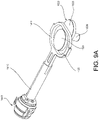
- FIG. 9A is a perspective view of the reciprocating mechanism shown in FIGS. 8A and 8B , in accordance with implementations described herein.
- FIG. 9B is a perspective view of the counterbalancing mechanism shown in FIGS. 8A and 8B , in accordance with implementations described herein.
- FIG. 9C is a perspective view of the reciprocating mechanism coupled with the counterbalancing mechanism shown in FIGS. 8A and 8B , in accordance with implementations described herein.
- FIGS. 10A and 10B are assembled views of the transmission mechanism, the reciprocating mechanism and the counterbalancing mechanism shown in FIGS. 8A and 8B in operation, in accordance with implementations described herein.
- FIGS. 11A and 11B are assembled views of the transmission mechanism, the reciprocating mechanism and the counterbalancing mechanism shown in FIGS. 8A and 8B in operation, including a bearing sleeve, in accordance with implementations described herein.
- FIGS. 12A-12D illustrate an arm and shoe assembly for a power-driven tool, in accordance with implementations described herein.
- FIG. 1 A schematic view of an exemplary power-driven tool 100 including a reciprocating mechanism is shown in FIG. 1 .
- the exemplary tool 100 may include a driving mechanism 110 generating a driving force, for example, a rotational driving force.
- a transmission mechanism 120 may be coupled between the driving mechanism 110 and a reciprocating mechanism 130 .
- the transmission mechanism 120 may transfer the driving force generated by the driving mechanism 110 to the reciprocating mechanism 130 .
- the transmission mechanism 120 may convert the rotational motion produced by the driving mechanism 110 into a linear force, or linear motion.
- the driving mechanism 110 , the transmission mechanism 120 , and the reciprocating mechanism 130 may be received in and/or coupled to a housing 190 .
- an output accessory 140 (such as, for example, a blade) may be coupled to the reciprocating mechanism 130 , and may extend from the housing 190 , to interact with a workpiece (not shown in FIG. 1 ).
- the driving mechanism 110 may be an electric motor that receives power from, for example, a power storage device (such as, for example, a battery), an external electrical power source, and the like.
- the driving mechanism 110 may be an air driven, or pneumatic motor, that is powered by compressed air introduced into the housing 190 from an external compressed air source. Other types of driving mechanisms, and other sources of power, may provide for power driven operation of the tool 100 .
- a relatively compact size, or profile may enhance the ability to access relatively small, confined work areas with the tool, thus enhancing utility of the tool.
- reduced vibration during operation may enhance precision, stability and utility of the tool, and may result in reduced operator fatigue during operation.
- vibration may be generated by multiple sources.
- vibration may be generated by interaction forces, or frictional forces, between an output accessory, such as a blade, and a work piece during operation.
- Inertial forces due to relative movement of internal components of the tool, may cause instability and/or vibration, whether or not the tool is engaged with a work piece.
- reaction forces are generated to accelerate/decelerate the component(s).
- the cyclic nature of this type of motion results in vibration experienced by the operator. All of this may cause opposite, reciprocal motion to be felt, or experienced, by the operator as vibration. This vibration may adversely affect precision and utility of the tool and increase operator fatigue.
- FIGS. 2A and 2B illustrate an exemplary power-driven tool 200 , in accordance with implementations described herein, in which FIG. 2A is a side view, and FIG. 2B is a top view.
- FIG. 3 is a side view of the exemplary power-driven reciprocating tool 200 shown in FIG. 2 , with a portion of a housing 290 of the tool 200 removed so that internal components of the tool 200 are visible.
- FIG. 4 is partial cross-sectional view of the tool shown in FIGS. 2A and 2B , taken along line A-A of FIG. 2B .
- the exemplary power-driven tool 200 shown in FIGS. 2A-4 is a power-driven reciprocating tool, and in particular, a power-driven reciprocating saw, simply for purposes of discussion and illustration.
- the exemplary power-driven tool 200 may include a driving mechanism 210 , for example, a motor 210 , a transmission mechanism 300 , and a reciprocating mechanism 400 .
- the driving mechanism 210 , the transmission mechanism 300 and the reciprocating mechanism 400 may be received in a tool housing 290 .
- the transmission 300 may convert a driving force, for example, a rotational force, generated by the driving mechanism 210 , to a linear force to be output by the reciprocating mechanism 400 .
- a counterweighting mechanism 500 may be coupled to the reciprocating mechanism 400 .
- the counterweighting mechanism 500 may counteract imbalances generated by the driving and reciprocating mechanisms 210 , 400 during operation.
- FIG. 5A is a cross-sectional view taken along line A-A of FIG. 2B
- FIG. 5B is an exploded perspective view, of the exemplary transmission mechanism 300 , the exemplary reciprocating mechanism 400 , and the exemplary counterbalancing mechanism 500 , of the exemplary tool 200 shown in FIGS. 2A-4
- FIG. 6A is a top view of the exemplary transmission mechanism 300 , with a portion of a housing removed so that internal components of the transmission mechanism 300 are visible, in accordance with implementations described herein.
- FIG. 6B is a top view of the reciprocating mechanism 400
- FIG. 6C is a top view of the counterbalancing mechanism 500 , in accordance with implementations described herein.
- FIG. 6D is a cross sectional view of the assembled transmission mechanism 300 , reciprocating mechanism 400 , and counterbalancing mechanism 500 , taken along line B-B of FIG. 2B , in accordance with implementations described herein.
- the transmission mechanism 300 may be received in a housing 390 .
- a planetary gear assembly 310 arranged in a carrier 320 , may be positioned in the housing 390 , aligned with the motor 210 .
- the planetary gear assembly 310 may include a central gear (also referred to as a sun gear) 312 and one or more planet gears 314 in meshed engagement with the sun gear 312 .
- An outer gear 316 may be in meshed engagement with the one or more planet gear(s) 314 .
- An output shaft 212 of the motor 210 may extend through a bushing 330 on an upper portion 322 of the carrier 320 , and into the gear assembly 310 , so that an end portion of the output shaft 212 of the motor 210 may be engaged with the sun gear 312 .
- the rotational force of the motor 210 output via the output shaft 212 , rotates the sun gear 312 , which in turn rotates the one or more planet gear(s) 314 coupled on the carrier 320 . Due to the meshed engagement of the planet gears 314 with the outer gear 316 , the rotation of the planet gears 314 causes the carrier 320 to rotate about the sun gear 312 .
- a pin 340 may extend downward, from a lower portion 324 of the carrier 320 .
- the pin 340 may be fixed to, or integrally formed with, the carrier 320 , such that the pin 340 rotates together with the carrier 320 about the sun gear 312 .
- the output shaft 212 of the motor 210 , the carrier 320 and the sun gear 312 are all aligned along and rotate about an axis C 1 .
- the pin 340 fixed to the carrier 320 , is aligned along an axis C 2 , offset from the axis C 1 , and revolves about the axis C 1 .
- Engagement of the pin 340 with the reciprocating mechanism 400 may drive reciprocating movement of a reciprocating shaft 410 , which may in turn drive reciprocating movement of an output mechanism, or accessory, such as, for example, a blade, coupled to the reciprocating mechanism 400
- the use of the exemplary planetary gear assembly 310 in the power-driven reciprocating tool 200 may provide for a relatively compact mechanism to transmit force from the motor 210 to an output mechanism of the tool 200 during operation.
- the relatively compact transmission mechanism 300 may, in turn, reduce an overall size, or profile of the tool 200 .
- an overall size, or dimension, or profile, of the tool 200 in a longitudinal direction L, or a longitudinal axis L, of the tool 200 may be reduced.
- an overall size, or dimension, or profile, of the tool 200 in a height direction H of the tool 200 may be reduced.
- the relatively compact tool profile afforded by the user of the planetary gear assembly 310 may provide for improve user control of the tool and may allow the user to work in and access smaller, more confined spaces using the tool 200 .
- the reciprocating mechanism 400 may include a reciprocating shaft 410 .
- a yoke 420 may be positioned at a first end of the reciprocating shaft 410
- a coupling device 440 may be positioned at a second end of the reciprocating shaft 410 .
- the coupling device 440 may detachably couple, for example, an accessory such as, for example, a blade, to the reciprocating mechanism 400 .
- a bushing 430 may be received in a slot 425 formed in the yoke 420 .
- the bushing 430 may be movable, for example, slidable, within the slot 425 .
- the pin 340 may be coupled in the bushing 430 , thereby coupling the transmission mechanism 300 to the reciprocating mechanism 400 .
- the counterbalancing mechanism 500 may include a counterbalance member (also referred to as a weight) 510 .
- An eccentric member 520 for example, a dual eccentric counter-stroke cam 520 , may be coupled to the counterbalance member 510 .
- the pin 340 may extend through the bushing 425 received in the yoke 420 , and into an opening 525 formed in the eccentric member 520 .
- the eccentric member 520 may be movably coupled, for example, rotatably coupled to an upper portion 512 of the counterbalance member 510 . In the exemplary implementation illustrated in FIGS.
- the eccentric member 520 (or a first eccentric counter-stroke cam 520 ) includes a first portion 521 (or a first eccentric counter-stroke disc 521 ) that is rotatably coupled to the counterbalance member 510 , and a second portion 523 (or a second eccentric counter-stroke disc 523 ) in which the opening 525 is formed to receive the pin 340 .
- a shaft 528 extending from the eccentric member 520 may be rotatably coupled in a corresponding recess 518 in the counterbalance member 510 to rotatably couple the eccentric member 520 to the counterbalance member 510 .
- the first portion 521 of the eccentric member 520 may be received in a recess 516 formed in the upper portion 512 of the counterbalance member 510 , with the first portion 521 coupled to a lower portion of the second portion 523 , at an offset from the second portion 523 of the eccentric member 520 .
- a shape, or internal contour, of the recess 516 may correspond to a shape, or external contour, of the first portion 521 of the eccentric member 520 .
- the eccentric member 520 may be substantially planar, with a first end portion thereof being rotatably coupled to the upper portion 512 of the counterbalance member 510 , and a second end portion thereof having the opening 525 formed therein.
- a wear plate (also referred to as a washer) 524 may be positioned on an upper surface of the second portion 523 of the eccentric member 520 .
- the engagement of the pin 340 , through the bushing 430 and into the opening 525 of the eccentric member 520 , may in turn cause the eccentric member 520 to revolve, and may convert the rotational force (generated by the motor 210 ) to a linear force output by the reciprocating mechanism 400 .
- the engagement of the pin 340 with the eccentric member 520 in this manner may also cause linear motion of the counterbalance member 510 , for example, linear motion of the counterbalance member 510 that is opposite the linear motion of the reciprocating mechanism 400 , to balance the linear motion of the reciprocating mechanism 400 .
- the balancing of the linear motion of the reciprocating mechanism 400 in this manner may reduce or substantially eliminate vibration due to the reciprocating forces generated during operation of the tool 200 . This will be described in more detail with respect to FIGS. 7A-7D .
- FIGS. 7A-7D are top views of the reciprocating mechanism 400 and the counterbalancing mechanism 500 in phased operation, in accordance with implementations described herein.
- the components of the reciprocating mechanism 400 and the counterbalancing mechanism 500 are shown at 0 degrees ( FIG. 7A ), 90 degrees ( FIG. 7B ), 180 degrees ( FIG. 7C ), and 270 degrees ( FIG. 7D ) in response to the rotational output force from the motor 210 , as described above.
- the pin 340 (not shown but received in the bushing 430 ), is positioned at an intermediate position in the slot 425 , between a first end 425 A of the slot 425 and a second end 425 B of the slot 425 .
- the 0-degree phase position shown in FIG. 7A may represent a first linear position (for example, a first extreme of travel of the reciprocating shaft 410 /yoke 420 , or maximum linear position) of the reciprocating shaft 410 along a linear reciprocating direction E, or a linear axis E.
- a first linear position for example, a first extreme of travel of the reciprocating shaft 410 /yoke 420 , or maximum linear position
- the reciprocating shaft 410 is in a far-left position along the linear reciprocating direction E, and the counterbalance member 510 is in a far-right position along the linear reciprocating direction E.
- the counterbalance member 510 may be positioned to balance the movement of the reciprocating shaft 410 .
- the first position of the reciprocating shaft 410 shown in FIG. 7A may represent a first linear position, or a most extended position, or a first extreme of travel of the reciprocating shaft 410 /yoke 420 , or a maximum linear position, of the reciprocating shaft 410 along the linear reciprocating direction E.
- Rotation of the output shaft 212 of the motor 210 causes the carrier 320 to rotate and causes the pin 340 to move together with the carrier 320 , as described above with respect to FIGS. 5A, 5B and 6A such that the pin 340 revolves around the axis C 1 of the motor output shaft 212 .
- this revolving movement of the pin 340 causes a corresponding movement of the eccentric member 520 , for example, in the direction of the arrow F.
- the eccentric member 520 (and the position of the pin 340 received in the opening 525 ) has rotated approximately 90 degrees about the axis C 1 , positioning the pin 340 /bushing 430 at the second end 425 B of the slot 425 , and causing the reciprocating shaft 410 to move linearly by a distance D 1 , in the linear reciprocating direction E 2 , from the 0 phase position shown in FIG. 7A .
- the 90-degree phase position shown in FIG. 7B may represent an intermediate linear position of the reciprocating shaft 410 .
- the movement of the pin 340 /bushing 430 and eccentric member 520 in this manner may also cause the counterbalance member 510 to move linearly, in the direction E 1 , opposite the linear movement of the reciprocating shaft 410 , to an intermediate linear position, thus balancing the movement of the reciprocating mechanism 400 .
- the 180-degree phase position shown in FIG. 7C may represent a second linear position (i.e., a second extreme of travel of the reciprocating shaft 410 /yoke 420 , opposite the first extreme of travel of the reciprocating shaft/yoke, or a minimum linear position, or a most withdrawn linear position) of the reciprocating shaft 410 along the linear reciprocating direction E.
- the movement of the pin 340 /bushing 430 and eccentric member 520 in this manner may also cause the counterbalance member 510 to move linearly, in the direction E 1 , opposite the linear movement of the reciprocating shaft 410 , to a second linear position, thus balancing the movement of the reciprocating mechanism 400 .
- the 270-degree phase position shown in FIG. 7C may represent an intermediate linear position of the reciprocating shaft 410 .
- the movement of the pin 340 /bushing 430 and eccentric member 520 in this manner may also cause the counterbalance member 510 to move linearly, in the direction E 2 , opposite the linear movement of the reciprocating shaft 410 , to an intermediate linear position as shown in FIG. 7D , thus balancing the movement of the reciprocating mechanism 400 .
- a bushing 445 positioned at a distal end of the reciprocating shaft 410 may support and guide the linear reciprocating movement of the reciprocating shaft 410 .
- a first guide plate 530 may be positioned at an upper portion 512 of the counterbalance member 510 to guide the linear reciprocating movement of the reciprocating mechanism 400 .
- the first guide plate 530 may be shaped so as to guide the linear reciprocating movement of the yoke 420 , as the eccentric member 520 rotates and the pin 340 /bushing 430 moves in the slot 425 , as described above.
- the size and/or the shape of the first guide plate 530 may restrict, or limit, a linear position of the yoke 420 , thus restricting, or limiting, further reciprocating movement of the reciprocating mechanism 400 beyond a set position.
- a second guide plate 540 may be positioned at a lower portion 514 of the counterbalance member 510 to guide the reciprocating movement of the counterbalance member 510 .
- the second guide plate 540 may be received in a recess formed in the lower portion 514 of the counterbalance member 510 , the recess having an internal contour corresponding to the external contour of the second guide plate 540 so as to guide the linear movement of the counterbalance member 510 , as shown in the exemplary implementation illustrated herein.
- the counterbalancing mechanism 500 that is opposite to the linear reciprocating motion of the reciprocating mechanism 400 , in the manner described above with respect to FIGS. 7A through 7D , may counter-balance the forces generated due to the conversion of the rotational force generated by the motor to a linear force to be output by the tool, and the reciprocating motion of the reciprocating mechanism 400 .
- the counter-balancing of these forces reduces vibratory forces output by the tool. Reduced vibration allows for more precise operation and control of the tool, and reduces user fatigue, thus enhancing utility of the tool.
- FIGS. 8A and 8B illustrate a motor 1210 , a transmission mechanism 1300 , a reciprocating mechanism 1400 , and a counterbalancing mechanism 1500 for a power-driven reciprocating tool, in accordance with implementations described herein.
- the reciprocating mechanism 1400 and the counterbalancing mechanism 1500 move in opposite linear directions to each other, through the action of a dual eccentric counter-stroke cam, such that the counterbalancing mechanism 1500 counter-balances the action of the reciprocating mechanism 1400 .
- at least a portion of the counterweighting provided by the counterbalancing mechanism 1500 is provided inline with the linear reciprocating action of the reciprocating mechanism 1500 , achieving a reduction in vibration output by the tool with a relatively compact system.
- FIG. 8A is an assembled perspective view
- FIG. 8B is an assembled perspective view with certain elements from FIG. 8A removed, of the motor 1210 , the transmission mechanism 1300 , the reciprocating mechanism 1400 , and the counterbalancing mechanism 1500 , in accordance with implementations described herein.
- the motor 1210 may be positioned inline with the transmission mechanism 1300 , including a planetary gear assembly 1310 , so that an output shaft of the motor 1210 may drive the planetary gear assembly 1310 , in a manner similar to that described above with respect to FIGS. 5A and 5B .
- the planetary gear assembly 1310 may, in turn, be arranged inline with the reciprocating mechanism 1400 .
- the planetary gear assembly 1310 may be arranged inline with, and coupled to, a dual eccentric stroke cam (also referred to as an eccentric member) 1520 , to in turn drive a reciprocating shaft 1410 of the reciprocating mechanism 1400 .
- a first counterweight member 1510 and a second counterweight member 1550 may be fixed to opposite end portions of a connecting plate 1540 , such that the first counterweight 1510 , the second counterweight 1550 , and the connecting plate 1540 move together.
- a shaft 1528 of the eccentric member 1520 extends through an elongated slot 1545 in the connecting plate 1540 and may be retained by a first plate 1610 and a bearing 1620 positioned below the connecting plate 1540 .
- FIG. 8B the reciprocating shaft 1410 and a first counterweight member 1510 have been removed, for illustrative purposes, so that the inline arrangement of the planetary gear assembly 1310 , the eccentric member 1520 , and the bearing 1620 is visible.
- FIG. 9A is a perspective view of the reciprocating mechanism 1400
- FIG. 9B is a perspective view of the counterbalancing mechanism 1500
- FIG. 9C is a perspective view of the reciprocating mechanism 1400 engaged with the counterbalancing mechanism 1500 .
- the reciprocating mechanism 1400 may include a yoke 1420 at a first end of the reciprocating shaft 1410 , and a coupling device 1440 at a second end of the reciprocating shaft 1410 , for coupling an external tool accessory to the reciprocating mechanism 1400 .
- a first eccentric counter-stroke disc (also referred to as a first portion) 1521 of the eccentric member 520 may be received, for example, movably or slidably received, in a slot 1425 formed in the yoke 1420 .
- the counterbalancing mechanism 1500 may include the connecting plate 1540 having the first counterweight member 1510 fixed to a first end thereof, and a second counterweight member 1550 fixed to a second end thereof.
- a first opening 1530 and a second opening 1535 may be formed in the first counterweight member 1510 .
- the shaft 1528 of the eccentric member 1520 may be movably, or slidably, received in the second opening 1535 as the shaft 1528 extends through the first counterweight member 1510 , through a corresponding slot 1545 in the connecting plate 1540 , through the first plate 1610 , and into the bearing 1620 (see FIG. 8A ).
- FIGS. 10A and 10B are assembled perspective views of the transmission mechanism 1300 , the reciprocating mechanism 1400 , and the counterbalancing mechanism 1500 , in accordance with implementations described herein.
- the reciprocating mechanism 1400 (the reciprocating shaft 1410 and yoke 1420 ) is in a first position, in which the reciprocating mechanism 1400 is in an extended, for example, a substantially fully extended state or maximum extended state, or at an extreme (maximum) end of travel.
- the counterbalancing mechanism 1500 (the first counterweight member 1510 , the connecting plate 1540 , and the second counterweight member 1550 ) is in a first position, so as to counter-balance the action of the reciprocating mechanism 1500 .
- the reciprocating mechanism 1400 and the counterbalancing mechanism 1500 may move to respective second positions, as shown in FIG. 10B . That is, in FIG. 10B , the reciprocating mechanism 1400 has moved in a direction F 1 , from the first position to a second position, and the counterbalancing mechanism 1500 has moved in the direction F 2 , from the first position to a second position. In the second position, the reciprocating mechanism 1400 is in a rearward, or retracted state, in which the reciprocating shaft 1410 is in a minimum extended state, or at an extreme (minimum) end of travel. In the second position, the counterbalancing mechanism 1500 has moved in a direction opposite that of the reciprocating mechanism 1500 , so as to counter-balance the action of the reciprocating mechanism 1500 .
- FIGS. 11A and 11B are assembled perspective views of the transmission mechanism 1300 , the reciprocating mechanism 1400 , and the counterbalancing mechanism 1500 , including a sleeve bearing 1660 , in accordance with implementations described herein.
- the sleeve bearing 1660 may be fitted on an outer circumferential surface of the reciprocating shaft 1410 .
- a locking tab 1670 of the sleeve bearing 1660 may move into and out of a slot 1570 formed in the second counterweight 1550 as the reciprocating mechanism 1400 and the counterbalancing mechanism 1500 move between the first and second positions shown in FIGS.
- Movement of the locking tab 1670 of the sleeve bearing 1660 into and out of the slot 1570 in the second counterweight member 1550 , as the reciprocating mechanism 1400 and the counterbalancing mechanism 1500 exhibit complementary reciprocating motion as described, may guide and maintain a relative position of the reciprocating mechanism 1400 and the counterbalancing mechanism 1500 .
- the second counterweight member 1550 may serve as a linear guide for the linear reciprocating movement of the reciprocating shaft 1410 , whether or not the sleeve bearing 1660 is included.
- features of the second counterweight member 1550 may be varied, based on, for example, an amount of counter-balancing required for a particular application, an amount of space allocated, and other such factors.
- a size and/or a shape of the second counterweight member 1550 may be adapted for a particular application, to increase or decrease an amount of counterweighting provided, to fit within a particular amount of allocated space and the like.
- a mass, or a density of material of the first counterweight member 1510 and/or the second counterweight member 1550 may be varied to accommodate an amount of counterweighting provided, adapt to an amount of allocated space, and the like.
- the coupling device 440 , 1440 of the tool may allow an external accessory such as, for example, a blade, to be removably attached to the tool.
- support arms 270 may be coupled to the housing 290 of the tool, and a shoe 280 may be coupled to distal ends of the support arms 270 , to support a position of the accessory relative to the coupling device 440 , 1440 , and relative to the tool.
- a profile of the support arms 270 may be contoured, or angled, so as to be inclined toward an accessory, such as a blade, coupled to the tool.
- the shoe 280 may include one or more cleats 285 at an end of the shoe 280 .
- the cleats 285 may allow an operator to temporarily suspend, or hang, or otherwise store the tool from a variety of different surfaces such as, for example, the rung of a ladder as shown in FIG. 12D , the edge of a sheet of building material, ledges, hooks, and the like.
- the exemplary implementation shown in FIGS. 12A-12D includes a cleat at a lower end of the shoe 280 .
- a cleat 285 may be provided at an upper end of the shoe 280 , and/or at both the upper end and the lower end of the shoe 280 .
Landscapes
- Engineering & Computer Science (AREA)
- General Engineering & Computer Science (AREA)
- Mechanical Engineering (AREA)
- Physics & Mathematics (AREA)
- Acoustics & Sound (AREA)
- Aviation & Aerospace Engineering (AREA)
- Sawing (AREA)
Abstract
Description
Claims (22)
Priority Applications (2)
| Application Number | Priority Date | Filing Date | Title |
|---|---|---|---|
| US16/450,538 US11453093B2 (en) | 2019-06-24 | 2019-06-24 | Reciprocating tool having planetary gear assembly and counterweighting assembly |
| EP20180206.3A EP3757427A1 (en) | 2019-06-24 | 2020-06-16 | Reciprocating tool having planetary gear assembly and counterweighting assembly |
Applications Claiming Priority (1)
| Application Number | Priority Date | Filing Date | Title |
|---|---|---|---|
| US16/450,538 US11453093B2 (en) | 2019-06-24 | 2019-06-24 | Reciprocating tool having planetary gear assembly and counterweighting assembly |
Publications (2)
| Publication Number | Publication Date |
|---|---|
| US20200398393A1 US20200398393A1 (en) | 2020-12-24 |
| US11453093B2 true US11453093B2 (en) | 2022-09-27 |
Family
ID=71103269
Family Applications (1)
| Application Number | Title | Priority Date | Filing Date |
|---|---|---|---|
| US16/450,538 Active 2041-02-01 US11453093B2 (en) | 2019-06-24 | 2019-06-24 | Reciprocating tool having planetary gear assembly and counterweighting assembly |
Country Status (2)
| Country | Link |
|---|---|
| US (1) | US11453093B2 (en) |
| EP (1) | EP3757427A1 (en) |
Cited By (2)
| Publication number | Priority date | Publication date | Assignee | Title |
|---|---|---|---|---|
| US20230082901A1 (en) * | 2021-09-10 | 2023-03-16 | Makita Corporation | Reciprocating cutting tool |
| US20230286128A1 (en) * | 2022-03-09 | 2023-09-14 | Black & Decker Inc. | Counterbalancing mechanism and power tool having same |
Families Citing this family (2)
| Publication number | Priority date | Publication date | Assignee | Title |
|---|---|---|---|---|
| CN113199082A (en) * | 2021-05-25 | 2021-08-03 | 南京久驰机电实业有限公司 | Reciprocating saw |
| CN115921985A (en) * | 2021-08-25 | 2023-04-07 | 南京泉峰科技有限公司 | cutting tool |
Citations (119)
| Publication number | Priority date | Publication date | Assignee | Title |
|---|---|---|---|---|
| US1525070A (en) | 1924-07-14 | 1925-02-03 | George B Coleman | Gearing |
| DE803142C (en) | 1949-03-29 | 1951-03-01 | Scintilla Ag | Crank gear |
| US2931402A (en) | 1957-03-22 | 1960-04-05 | Walter A Papworth | Power driven reciprocable cutting tool |
| US2949944A (en) | 1958-06-27 | 1960-08-23 | Oster Mfg Co John | Portable hand held saw |
| US2970484A (en) | 1959-04-20 | 1961-02-07 | Robbins & Myers | Balancing mechanism for sabre saws and the like |
| DE1870185U (en) | 1957-12-03 | 1963-04-11 | Stanley Works | JACK SAW OR JIG SAW. |
| US3095748A (en) | 1961-06-16 | 1963-07-02 | Porter Cable Machine Co | Orbital motion tool |
| US3205721A (en) | 1960-06-13 | 1965-09-14 | Rockwell Mfg Co | Saber saws |
| US3457796A (en) | 1966-06-23 | 1969-07-29 | Rockwell Mfg Co | Tool |
| DE1673054A1 (en) | 1967-12-19 | 1971-08-19 | Sp K Bjuro Analititscheskogo P | Single-beam absorption analyzer for gases, vapors and liquids |
| US3655021A (en) | 1970-11-23 | 1972-04-11 | Froio Corp | Imbalanced braking device |
| US3688522A (en) | 1969-12-29 | 1972-09-05 | Hilti Ag | Overload clutch permitting torque transmission during overload |
| US3729823A (en) | 1971-05-05 | 1973-05-01 | Gardner Denver Co | Reciprocation drive and counterweight arrangement for power saws |
| US3766362A (en) | 1972-11-24 | 1973-10-16 | R Pell | Averaging apparatus |
| US3978862A (en) | 1974-08-26 | 1976-09-07 | Stryker Corporation | Surgical cutting device |
| US4145811A (en) | 1977-10-31 | 1979-03-27 | Jarvis Products Corporation | Reciprocating saw |
| GB2042973A (en) | 1979-03-15 | 1980-10-01 | Freund R | Saw |
| FR2451242A1 (en) | 1979-03-14 | 1980-10-10 | Freund Reinhard Maschbau | Reciprocating drive for piercing saw - has crank driven saw ram and reciprocating counter balancing opposite travelling mass |
| US4482042A (en) | 1982-05-17 | 1984-11-13 | Unr Industries, Inc. | Retarder device for moving objects |
| US5025562A (en) | 1990-03-01 | 1991-06-25 | Milwaukee Electric Tool Corporation | Counterbalanced reciprocating mechanism |
| US5050307A (en) | 1990-03-01 | 1991-09-24 | Milwaukee Electric Tool Corporation | Wobble plate drive |
| US5099705A (en) | 1989-12-05 | 1992-03-31 | Konstantins Dravnieks | Hand-held reciprocating working tool |
| US5134777A (en) | 1991-12-05 | 1992-08-04 | Skil Corporation | Adjustable stroke reciprocating mechanism for a power tool |
| US5212887A (en) * | 1992-03-18 | 1993-05-25 | S-B Power Tool Company | Counterbalanced orbital drive mechanism for saws and the like |
| USRE35258E (en) | 1990-11-13 | 1996-06-04 | Milwaukee Electric Tool Corporation | Counterbalanced reciprocating mechanism |
| US5561909A (en) | 1995-06-26 | 1996-10-08 | Berg; Donald N. E. | Battery operated saw |
| US5566458A (en) | 1994-12-13 | 1996-10-22 | Milwaukee Electric Tool Corporation | Clutch mechanism for reciprocating saws |
| US5598636A (en) | 1994-08-17 | 1997-02-04 | Ryobi Motor Products | Reciprocating drive saw mechanism |
| US5607023A (en) | 1994-12-13 | 1997-03-04 | Milwaukee Electric Tool Corp. | Impact absorption mechanism for power tools |
| US5689891A (en) | 1994-12-13 | 1997-11-25 | Milwaukee Electric Tool Corp. | Clutch mechanism for reciprocating saws |
| US5964039A (en) | 1992-07-28 | 1999-10-12 | Matsushita Electric Works, Ltd. | Cutting method and saw tool |
| US6012346A (en) | 1998-09-18 | 2000-01-11 | New Hampshire Ball Bearing, Inc. | Low vibration motion translation system |
| USRE37211E1 (en) | 1994-12-13 | 2001-06-12 | Milwaukee Electric Tool Corporation | Clutch mechanism for reciprocating saws |
| US6249979B1 (en) | 1998-08-13 | 2001-06-26 | Milwaukee Electric Tool Corporation | Orbital reciprocating saw |
| US6282797B1 (en) | 1999-03-12 | 2001-09-04 | Hitachi Koki Co., Ltd. | Cutting mechanism for saber saw |
| US6286217B1 (en) | 1998-04-09 | 2001-09-11 | Black & Decker Inc. | Reciprocating saw with pivoted arm drive |
| US6357125B1 (en) * | 2000-04-24 | 2002-03-19 | S-B Power Tool Company | Adjustable stroke mechanism for a scotch yoke assembly |
| USD455328S1 (en) | 2001-08-31 | 2002-04-09 | S-B Power Tool Company | Articulated jigsaw |
| US6370781B1 (en) * | 1998-12-04 | 2002-04-16 | Hitachi Koki Co., Ltd. | Reciprocating tool |
| US6508151B1 (en) | 1996-08-19 | 2003-01-21 | Milwaukee Electric Tool Corporation | Reciprocating saw with rocker motion |
| US20030121389A1 (en) | 2002-01-02 | 2003-07-03 | Wheeler Thomas J. | Reciprocating saw |
| US6634437B1 (en) | 1998-04-23 | 2003-10-21 | Gary Rudolph | Apparatus and method for rotary motion conversion and waste product collection unit |
| US6634107B2 (en) | 1999-03-12 | 2003-10-21 | Hitachi Koki Co., Ltd. | Cutting mechanism for a saber saw |
| US6662455B2 (en) | 2001-03-28 | 2003-12-16 | Hitachi Koki Co., Ltd. | Cutting mechanism for a saber saw |
| US6758119B1 (en) | 1996-08-19 | 2004-07-06 | Milwaukee Electric Tool Corporation | Reciprocating saw with rocker motion |
| US20040194987A1 (en) | 2001-03-07 | 2004-10-07 | Andreas Hanke | Hammer |
| US20040231170A1 (en) | 2000-11-02 | 2004-11-25 | Neitzell Roger Dean | Handle arrangement for a reciprocating saw |
| US20040261273A1 (en) | 2003-06-24 | 2004-12-30 | Griep David B. | Drive mechanism and power tool |
| US20050016001A1 (en) | 2003-06-24 | 2005-01-27 | Milwaukee Electric Tool Corporation | Drive mechanism and power tool |
| US6860886B1 (en) | 1999-08-19 | 2005-03-01 | Hee-Young Lee | Reciprocating surgical tool for use at variable angles and in multiple directions |
| US20050252670A1 (en) * | 2004-05-12 | 2005-11-17 | Credo Technology Corporation | Rotary to reciprocating motion conversion attachment for a power rotary hand tool |
| US6976313B2 (en) | 2002-04-15 | 2005-12-20 | International Concepts, Inc. | Battery-powered carving knife having a rechargeable battery pack |
| US20060124331A1 (en) | 2002-09-13 | 2006-06-15 | Michael Stirm | Rotary tool |
| US7127973B2 (en) | 1998-02-09 | 2006-10-31 | Milwaukee Electric Tool Corporation | Reciprocating saw |
| US20070017684A1 (en) | 2003-03-21 | 2007-01-25 | Micheal Stirm | Vibration reduction apparatus for power tool and power tool incorporating such apparatus |
| US7191847B2 (en) | 2003-12-11 | 2007-03-20 | Hilti Aktiengesellschaft | Drive for a motor-driven hand-held tool |
| US20070074407A1 (en) | 2005-09-30 | 2007-04-05 | Serdynski David P | Tool and method of using same |
| US20070135803A1 (en) | 2005-09-14 | 2007-06-14 | Amir Belson | Methods and apparatus for performing transluminal and other procedures |
| US7363713B2 (en) | 2003-06-23 | 2008-04-29 | Makita Corporation | Reciprocating power tool |
| DE102007062869A1 (en) | 2007-02-13 | 2008-08-14 | Robert Bosch Gmbh | Linkage drive device for a reciprocating tool |
| DE102007017408B3 (en) | 2007-04-13 | 2008-08-28 | Festool Gmbh | Hacksaw machine i.e. jigsaw, has mass balancing arrangements that rotate together in opposite directions during operation such that individual balance points of arrangements add to balance point formed by mass balancing device |
| US20080251568A1 (en) | 2007-04-13 | 2008-10-16 | Michael Zemlok | Powered surgical instrument |
| US20080287944A1 (en) | 2001-09-28 | 2008-11-20 | Angiodynamics, Inc. | Tissue ablation apparatus and method |
| US20080289843A1 (en) | 2006-11-10 | 2008-11-27 | Joel Townsan | Electric hand screwdriver with adjustable head |
| US20080308606A1 (en) | 2007-06-18 | 2008-12-18 | Timm Richard W | Surgical stapling and cutting instrument with improved firing system |
| JP2009083332A (en) | 2007-09-28 | 2009-04-23 | Hitachi Koki Co Ltd | Portable electric saw |
| JP2009101432A (en) | 2007-10-19 | 2009-05-14 | Hitachi Koki Co Ltd | Portable electric saw |
| US7637018B2 (en) | 2005-09-30 | 2009-12-29 | Positec Power Tools (Suzhou) Co. Ltd. | Power tool |
| US7707729B2 (en) | 2007-02-02 | 2010-05-04 | Robert Bosch Gmbh | Drive mechanism for a reciprocating tool |
| US20100162579A1 (en) | 2008-03-07 | 2010-07-01 | Michael Naughton | Reciprocating power tool having a counterbalance device |
| US7818887B2 (en) | 2006-07-07 | 2010-10-26 | Robert Bosch Gmbh | Handheld power tool, in particular handheld power saw |
| US20100320252A1 (en) | 2009-06-19 | 2010-12-23 | Tyco Healthcare Group Lp | Flexible surgical stapler with motor in the head |
| US20110107608A1 (en) | 2009-07-23 | 2011-05-12 | Brian Wattenbach | Reciprocating saw |
| US20110139475A1 (en) | 2008-07-28 | 2011-06-16 | Wacker Neuson Se | Impact device having an impact mechanism lubricating device |
| JP2011115912A (en) | 2009-12-04 | 2011-06-16 | Hitachi Koki Co Ltd | Reciprocating tool |
| US7996996B2 (en) | 2003-08-01 | 2011-08-16 | Makita Corporation | Reciprocating power tool |
| US20110315413A1 (en) | 2010-06-25 | 2011-12-29 | Mako Surgical Corp. | Kit-Of Parts for Multi-Functional Tool, Drive Unit, and Operating Members |
| US20120096721A1 (en) * | 2010-10-25 | 2012-04-26 | Sinur Robert A | Reciprocating saw |
| US8230608B2 (en) | 2008-10-23 | 2012-07-31 | Robert Bosch Gmbh | Progressive force cut path drive mechanism for a reciprocating tool |
| US20120192440A1 (en) * | 2011-01-27 | 2012-08-02 | Jerabek Jesse J | Power tool with reciprocating blade |
| US20120261153A1 (en) | 2004-08-27 | 2012-10-18 | Makita Coporation | Power tool |
| US8307910B2 (en) | 2010-04-07 | 2012-11-13 | Robert Bosch Gmbh | Drive mechanism for a reciprocating tool |
| USD674263S1 (en) | 2010-10-15 | 2013-01-15 | Robert Bosch Gmbh | Saw |
| US20130019483A1 (en) | 2011-04-01 | 2013-01-24 | Michael Naughton | Reciprocating saw, such as a jigsaw |
| US20130062090A1 (en) | 2011-03-11 | 2013-03-14 | Stanley D. Winnard | Handheld drive device |
| US8403075B2 (en) | 2007-12-19 | 2013-03-26 | Robert Bosch Gmbh | Wobble drive of a hand-held power tool |
| US8407901B2 (en) | 2008-10-23 | 2013-04-02 | Robert Bosch Gmbh | Drive mechanism for a reciprocating tool |
| US20130199812A1 (en) | 2012-02-04 | 2013-08-08 | Andreas Stihl Ag & Co. Kg | Handheld work apparatus |
| US20130247391A1 (en) | 2012-03-26 | 2013-09-26 | Black & Decker Inc. | Power Tool |
| DE102012210678A1 (en) | 2012-06-25 | 2014-01-02 | Robert Bosch Gmbh | Hand tool |
| US20140171966A1 (en) | 2007-01-10 | 2014-06-19 | Ethicon Endo-Surgery, Inc. | Surgical instrument with wireless communication between a control unit of a robotic system and remote sensor |
| US8763722B2 (en) | 2008-06-24 | 2014-07-01 | Robert Bosch Gmbh | Power tool having clutch device |
| US20140245620A1 (en) | 2013-02-06 | 2014-09-04 | Robert Bosch Gmbh | Portable power tool actuating element for a jigsaw, and jigsaw |
| US20140299345A1 (en) | 2011-12-30 | 2014-10-09 | Campbell Hausfeld / Scott Fetzer Company | Hand-held tools and components thereof |
| US8905153B2 (en) | 2008-06-24 | 2014-12-09 | Robert Bosch Gmbh | Method for operating a power tool having a clutch device |
| CN104209586A (en) | 2013-05-29 | 2014-12-17 | 博世电动工具(中国)有限公司 | Electric tool |
| US20150136433A1 (en) | 2012-05-25 | 2015-05-21 | Robert Bosch Gmbh | Percussion Unit |
| US9132491B2 (en) | 2008-03-07 | 2015-09-15 | Milwaukee Electric Tool Corporation | Portable battery-powered reciprocating saw |
| WO2015145912A1 (en) | 2014-03-27 | 2015-10-01 | 株式会社 マキタ | Electric tool |
| US9156097B2 (en) | 2012-03-20 | 2015-10-13 | Milwaukee Electric Tool Corporation | Reciprocating saw blade clamp |
| WO2015155912A1 (en) | 2014-04-08 | 2015-10-15 | 株式会社 マキタ | Electrically driven tool |
| US20150296719A1 (en) * | 2005-09-07 | 2015-10-22 | Black & Decker Inc. | Power tool with magnetic blade coupling |
| US9393681B2 (en) | 2012-06-13 | 2016-07-19 | Robert Bosch Gmbh | Transmission device |
| EP3053686A1 (en) | 2013-10-04 | 2016-08-10 | Hitachi Koki Co., Ltd. | Reciprocating tool |
| US9470273B2 (en) | 2011-04-27 | 2016-10-18 | Mekra Lang Gmbh & Co. Kg | Automatically switching clutch for a motor vehicle exterior mirror adjustment means |
| US9561552B2 (en) | 2011-02-09 | 2017-02-07 | Robert Bosch Gmbh | Tool machine with an output spindle that moves back and forth |
| US9573207B2 (en) | 2013-05-09 | 2017-02-21 | Makita Corporation | Reciprocating cutting tool |
| US9724771B2 (en) | 2011-01-31 | 2017-08-08 | Makita Corporation | Reciprocating power tool |
| DE102017115754A1 (en) | 2016-07-22 | 2018-01-25 | Makita Corporation | Tool with float |
| US10144106B2 (en) | 2015-11-02 | 2018-12-04 | Lake Country Manufacturing, Inc. | Adjustable stroke mechanism for random orbital machine |
| US20180370012A1 (en) | 2017-06-26 | 2018-12-27 | Bosch Power Tools (China) Co. Ltd. | Electric Power Tool |
| US20190061081A1 (en) | 2016-01-29 | 2019-02-28 | Hilti Aktiengesellschaft | Portable power tool |
| US10259060B2 (en) | 2015-04-17 | 2019-04-16 | Makita Corporation | Reciprocating tool |
| US20200063827A1 (en) | 2018-08-27 | 2020-02-27 | GM Global Technology Operations LLC | In-line balance shaft system for internal combustion engines |
| US20200070265A1 (en) | 2017-05-31 | 2020-03-05 | Bosch Power Tools (China) Co., Ltd. | Power Tool |
| EP3038779B1 (en) | 2013-08-26 | 2020-03-25 | Hilti Aktiengesellschaft | Jigsaw transmission |
| EP3038780B1 (en) | 2013-08-26 | 2020-04-08 | Hilti Aktiengesellschaft | Counterweight device |
| EP3632603A1 (en) | 2017-05-31 | 2020-04-08 | Koki Holdings Co., Ltd. | Reciprocating tool |
| US11229963B2 (en) | 2019-06-24 | 2022-01-25 | Black & Decker Inc. | Force and moment canceling reciprocating mechanism and power tool having same |
Family Cites Families (4)
| Publication number | Priority date | Publication date | Assignee | Title |
|---|---|---|---|---|
| US2695522A (en) * | 1953-03-17 | 1954-11-30 | Walter A Papworth | Power hand tool |
| GB2181693B (en) * | 1985-09-27 | 1989-05-10 | Black & Decker Inc | Improvements in and relating to power tools |
| US6170159B1 (en) * | 1996-10-29 | 2001-01-09 | Andreas Stihl Ag & Co. | Manually guided implement having a drive motor |
| GB2488742B (en) * | 2009-12-14 | 2014-09-17 | Bosch Tool Corp | Jigsaw |
-
2019
- 2019-06-24 US US16/450,538 patent/US11453093B2/en active Active
-
2020
- 2020-06-16 EP EP20180206.3A patent/EP3757427A1/en active Pending
Patent Citations (144)
| Publication number | Priority date | Publication date | Assignee | Title |
|---|---|---|---|---|
| US1525070A (en) | 1924-07-14 | 1925-02-03 | George B Coleman | Gearing |
| DE803142C (en) | 1949-03-29 | 1951-03-01 | Scintilla Ag | Crank gear |
| US2931402A (en) | 1957-03-22 | 1960-04-05 | Walter A Papworth | Power driven reciprocable cutting tool |
| DE1870185U (en) | 1957-12-03 | 1963-04-11 | Stanley Works | JACK SAW OR JIG SAW. |
| US2949944A (en) | 1958-06-27 | 1960-08-23 | Oster Mfg Co John | Portable hand held saw |
| US2970484A (en) | 1959-04-20 | 1961-02-07 | Robbins & Myers | Balancing mechanism for sabre saws and the like |
| US3205721A (en) | 1960-06-13 | 1965-09-14 | Rockwell Mfg Co | Saber saws |
| US3095748A (en) | 1961-06-16 | 1963-07-02 | Porter Cable Machine Co | Orbital motion tool |
| US3457796A (en) | 1966-06-23 | 1969-07-29 | Rockwell Mfg Co | Tool |
| DE1673054A1 (en) | 1967-12-19 | 1971-08-19 | Sp K Bjuro Analititscheskogo P | Single-beam absorption analyzer for gases, vapors and liquids |
| US3688522A (en) | 1969-12-29 | 1972-09-05 | Hilti Ag | Overload clutch permitting torque transmission during overload |
| US3655021A (en) | 1970-11-23 | 1972-04-11 | Froio Corp | Imbalanced braking device |
| US3729823A (en) | 1971-05-05 | 1973-05-01 | Gardner Denver Co | Reciprocation drive and counterweight arrangement for power saws |
| US3766362A (en) | 1972-11-24 | 1973-10-16 | R Pell | Averaging apparatus |
| US3978862A (en) | 1974-08-26 | 1976-09-07 | Stryker Corporation | Surgical cutting device |
| US4145811A (en) | 1977-10-31 | 1979-03-27 | Jarvis Products Corporation | Reciprocating saw |
| FR2451242A1 (en) | 1979-03-14 | 1980-10-10 | Freund Reinhard Maschbau | Reciprocating drive for piercing saw - has crank driven saw ram and reciprocating counter balancing opposite travelling mass |
| GB2042973A (en) | 1979-03-15 | 1980-10-01 | Freund R | Saw |
| US4482042A (en) | 1982-05-17 | 1984-11-13 | Unr Industries, Inc. | Retarder device for moving objects |
| US5099705A (en) | 1989-12-05 | 1992-03-31 | Konstantins Dravnieks | Hand-held reciprocating working tool |
| US5025562A (en) | 1990-03-01 | 1991-06-25 | Milwaukee Electric Tool Corporation | Counterbalanced reciprocating mechanism |
| US5050307A (en) | 1990-03-01 | 1991-09-24 | Milwaukee Electric Tool Corporation | Wobble plate drive |
| USRE35258E (en) | 1990-11-13 | 1996-06-04 | Milwaukee Electric Tool Corporation | Counterbalanced reciprocating mechanism |
| US5134777A (en) | 1991-12-05 | 1992-08-04 | Skil Corporation | Adjustable stroke reciprocating mechanism for a power tool |
| US5212887A (en) * | 1992-03-18 | 1993-05-25 | S-B Power Tool Company | Counterbalanced orbital drive mechanism for saws and the like |
| EP0561473B1 (en) | 1992-03-18 | 1998-01-21 | S-B Power Tool Company | Counterbalanced orbital drive mechanism for saws and the like |
| US5964039A (en) | 1992-07-28 | 1999-10-12 | Matsushita Electric Works, Ltd. | Cutting method and saw tool |
| US5598636A (en) | 1994-08-17 | 1997-02-04 | Ryobi Motor Products | Reciprocating drive saw mechanism |
| USRE37529E1 (en) | 1994-12-13 | 2002-01-29 | Milwaukee Tool Corporation | Clutch mechanism for reciprocating saws |
| USRE38606E1 (en) | 1994-12-13 | 2004-10-05 | Milwaukee Electric Tool Corporation | Clutch mechanism for reciprocating saws |
| US5607023A (en) | 1994-12-13 | 1997-03-04 | Milwaukee Electric Tool Corp. | Impact absorption mechanism for power tools |
| US5566458A (en) | 1994-12-13 | 1996-10-22 | Milwaukee Electric Tool Corporation | Clutch mechanism for reciprocating saws |
| USRE37211E1 (en) | 1994-12-13 | 2001-06-12 | Milwaukee Electric Tool Corporation | Clutch mechanism for reciprocating saws |
| US5689891A (en) | 1994-12-13 | 1997-11-25 | Milwaukee Electric Tool Corp. | Clutch mechanism for reciprocating saws |
| US5561909A (en) | 1995-06-26 | 1996-10-08 | Berg; Donald N. E. | Battery operated saw |
| US6829831B1 (en) | 1996-08-19 | 2004-12-14 | Milwaukee Electric Tool Corporation | Reciprocating saw with rocker motion |
| US6758119B1 (en) | 1996-08-19 | 2004-07-06 | Milwaukee Electric Tool Corporation | Reciprocating saw with rocker motion |
| US6508151B1 (en) | 1996-08-19 | 2003-01-21 | Milwaukee Electric Tool Corporation | Reciprocating saw with rocker motion |
| US7448137B2 (en) | 1998-02-09 | 2008-11-11 | Milwaukee Electric Tool Corporation | Reciprocating saw |
| US7127973B2 (en) | 1998-02-09 | 2006-10-31 | Milwaukee Electric Tool Corporation | Reciprocating saw |
| US6286217B1 (en) | 1998-04-09 | 2001-09-11 | Black & Decker Inc. | Reciprocating saw with pivoted arm drive |
| US6634437B1 (en) | 1998-04-23 | 2003-10-21 | Gary Rudolph | Apparatus and method for rotary motion conversion and waste product collection unit |
| US6249979B1 (en) | 1998-08-13 | 2001-06-26 | Milwaukee Electric Tool Corporation | Orbital reciprocating saw |
| US7188425B2 (en) | 1998-08-13 | 2007-03-13 | Milwaukee Electric Tool Corporation | Reciprocating saw |
| US6851193B2 (en) | 1998-08-13 | 2005-02-08 | Milwaukee Electric Tool Corp | Reciprocating saw |
| US6012346A (en) | 1998-09-18 | 2000-01-11 | New Hampshire Ball Bearing, Inc. | Low vibration motion translation system |
| US6370781B1 (en) * | 1998-12-04 | 2002-04-16 | Hitachi Koki Co., Ltd. | Reciprocating tool |
| US6634107B2 (en) | 1999-03-12 | 2003-10-21 | Hitachi Koki Co., Ltd. | Cutting mechanism for a saber saw |
| US6282797B1 (en) | 1999-03-12 | 2001-09-04 | Hitachi Koki Co., Ltd. | Cutting mechanism for saber saw |
| US6877235B2 (en) | 1999-03-12 | 2005-04-12 | Hitachi Koki Co., Ltd. | Cutting mechanism for a saber saw |
| US6860886B1 (en) | 1999-08-19 | 2005-03-01 | Hee-Young Lee | Reciprocating surgical tool for use at variable angles and in multiple directions |
| US6357125B1 (en) * | 2000-04-24 | 2002-03-19 | S-B Power Tool Company | Adjustable stroke mechanism for a scotch yoke assembly |
| US20040231170A1 (en) | 2000-11-02 | 2004-11-25 | Neitzell Roger Dean | Handle arrangement for a reciprocating saw |
| US20040194987A1 (en) | 2001-03-07 | 2004-10-07 | Andreas Hanke | Hammer |
| US6662455B2 (en) | 2001-03-28 | 2003-12-16 | Hitachi Koki Co., Ltd. | Cutting mechanism for a saber saw |
| USD455328S1 (en) | 2001-08-31 | 2002-04-09 | S-B Power Tool Company | Articulated jigsaw |
| US20080287944A1 (en) | 2001-09-28 | 2008-11-20 | Angiodynamics, Inc. | Tissue ablation apparatus and method |
| US20030121389A1 (en) | 2002-01-02 | 2003-07-03 | Wheeler Thomas J. | Reciprocating saw |
| US7506447B2 (en) | 2002-01-02 | 2009-03-24 | Black & Decker Inc. | Reciprocating saw |
| US6976313B2 (en) | 2002-04-15 | 2005-12-20 | International Concepts, Inc. | Battery-powered carving knife having a rechargeable battery pack |
| US20060124331A1 (en) | 2002-09-13 | 2006-06-15 | Michael Stirm | Rotary tool |
| US20070017684A1 (en) | 2003-03-21 | 2007-01-25 | Micheal Stirm | Vibration reduction apparatus for power tool and power tool incorporating such apparatus |
| EP2119536B1 (en) | 2003-03-21 | 2017-08-23 | Black & Decker Inc. | Power tool incorporating vibration reduction apparatus |
| US7363713B2 (en) | 2003-06-23 | 2008-04-29 | Makita Corporation | Reciprocating power tool |
| US7793420B2 (en) | 2003-06-24 | 2010-09-14 | Milwaukee Electric Tool Corporation | Drive mechanism and power tool |
| US20040261273A1 (en) | 2003-06-24 | 2004-12-30 | Griep David B. | Drive mechanism and power tool |
| US20050016001A1 (en) | 2003-06-24 | 2005-01-27 | Milwaukee Electric Tool Corporation | Drive mechanism and power tool |
| US8371032B2 (en) | 2003-08-01 | 2013-02-12 | Makita Corporation | Power tool with vibration reducing mechanism |
| US7996996B2 (en) | 2003-08-01 | 2011-08-16 | Makita Corporation | Reciprocating power tool |
| US7191847B2 (en) | 2003-12-11 | 2007-03-20 | Hilti Aktiengesellschaft | Drive for a motor-driven hand-held tool |
| US20050252670A1 (en) * | 2004-05-12 | 2005-11-17 | Credo Technology Corporation | Rotary to reciprocating motion conversion attachment for a power rotary hand tool |
| US20120261153A1 (en) | 2004-08-27 | 2012-10-18 | Makita Coporation | Power tool |
| US20150296719A1 (en) * | 2005-09-07 | 2015-10-22 | Black & Decker Inc. | Power tool with magnetic blade coupling |
| US20070135803A1 (en) | 2005-09-14 | 2007-06-14 | Amir Belson | Methods and apparatus for performing transluminal and other procedures |
| DE102006041430B4 (en) | 2005-09-30 | 2015-03-19 | Positec Power Tools (Suzhou) Co., Ltd. | Machine tool with motor drive |
| US7637018B2 (en) | 2005-09-30 | 2009-12-29 | Positec Power Tools (Suzhou) Co. Ltd. | Power tool |
| US20070074407A1 (en) | 2005-09-30 | 2007-04-05 | Serdynski David P | Tool and method of using same |
| US7818887B2 (en) | 2006-07-07 | 2010-10-26 | Robert Bosch Gmbh | Handheld power tool, in particular handheld power saw |
| US20080289843A1 (en) | 2006-11-10 | 2008-11-27 | Joel Townsan | Electric hand screwdriver with adjustable head |
| US20140171966A1 (en) | 2007-01-10 | 2014-06-19 | Ethicon Endo-Surgery, Inc. | Surgical instrument with wireless communication between a control unit of a robotic system and remote sensor |
| US7707729B2 (en) | 2007-02-02 | 2010-05-04 | Robert Bosch Gmbh | Drive mechanism for a reciprocating tool |
| DE102007062869A1 (en) | 2007-02-13 | 2008-08-14 | Robert Bosch Gmbh | Linkage drive device for a reciprocating tool |
| EP1980351A2 (en) | 2007-04-13 | 2008-10-15 | Festool GmbH | Hacksaw machine |
| DE102007017408B3 (en) | 2007-04-13 | 2008-08-28 | Festool Gmbh | Hacksaw machine i.e. jigsaw, has mass balancing arrangements that rotate together in opposite directions during operation such that individual balance points of arrangements add to balance point formed by mass balancing device |
| US20080251568A1 (en) | 2007-04-13 | 2008-10-16 | Michael Zemlok | Powered surgical instrument |
| US20080308607A1 (en) | 2007-06-18 | 2008-12-18 | Timm Richard W | Surgical stapling and cutting instrument with improved closure system |
| US20080308602A1 (en) | 2007-06-18 | 2008-12-18 | Timm Richard W | Surgical stapling and cutting instruments |
| US20080308606A1 (en) | 2007-06-18 | 2008-12-18 | Timm Richard W | Surgical stapling and cutting instrument with improved firing system |
| JP2009083332A (en) | 2007-09-28 | 2009-04-23 | Hitachi Koki Co Ltd | Portable electric saw |
| JP2009101432A (en) | 2007-10-19 | 2009-05-14 | Hitachi Koki Co Ltd | Portable electric saw |
| US8403075B2 (en) | 2007-12-19 | 2013-03-26 | Robert Bosch Gmbh | Wobble drive of a hand-held power tool |
| US9132491B2 (en) | 2008-03-07 | 2015-09-15 | Milwaukee Electric Tool Corporation | Portable battery-powered reciprocating saw |
| US9233427B2 (en) | 2008-03-07 | 2016-01-12 | Milwaukee Electric Tool Corporation | Portable battery-powered reciprocating saw |
| US20100162579A1 (en) | 2008-03-07 | 2010-07-01 | Michael Naughton | Reciprocating power tool having a counterbalance device |
| US9061411B2 (en) | 2008-03-07 | 2015-06-23 | Milwaukee Electric Tool Corporation | Reciprocating power tool having a counterbalance device |
| US8407902B2 (en) | 2008-03-07 | 2013-04-02 | Milwaukee Electric Tool Corporation | Reciprocating power tool having a counterbalance device |
| US8905153B2 (en) | 2008-06-24 | 2014-12-09 | Robert Bosch Gmbh | Method for operating a power tool having a clutch device |
| US8763722B2 (en) | 2008-06-24 | 2014-07-01 | Robert Bosch Gmbh | Power tool having clutch device |
| US20110139475A1 (en) | 2008-07-28 | 2011-06-16 | Wacker Neuson Se | Impact device having an impact mechanism lubricating device |
| US8407901B2 (en) | 2008-10-23 | 2013-04-02 | Robert Bosch Gmbh | Drive mechanism for a reciprocating tool |
| US8230608B2 (en) | 2008-10-23 | 2012-07-31 | Robert Bosch Gmbh | Progressive force cut path drive mechanism for a reciprocating tool |
| US20100320252A1 (en) | 2009-06-19 | 2010-12-23 | Tyco Healthcare Group Lp | Flexible surgical stapler with motor in the head |
| US9579735B2 (en) | 2009-07-23 | 2017-02-28 | Milwaukee Electric Tool Corporation | Reciprocating saw |
| US20170129026A1 (en) | 2009-07-23 | 2017-05-11 | Milwaukee Electric Tool Corporation | Reciprocating saw |
| US20110107608A1 (en) | 2009-07-23 | 2011-05-12 | Brian Wattenbach | Reciprocating saw |
| JP2011115912A (en) | 2009-12-04 | 2011-06-16 | Hitachi Koki Co Ltd | Reciprocating tool |
| US9272347B2 (en) | 2010-04-07 | 2016-03-01 | Robert Bosch Gmbh | Drive mechanism for a reciprocating tool |
| US20130055576A1 (en) | 2010-04-07 | 2013-03-07 | Robert Bosch Gmbh | Drive Mechanism for a Reciprocating Tool |
| US8307910B2 (en) | 2010-04-07 | 2012-11-13 | Robert Bosch Gmbh | Drive mechanism for a reciprocating tool |
| US20110315413A1 (en) | 2010-06-25 | 2011-12-29 | Mako Surgical Corp. | Kit-Of Parts for Multi-Functional Tool, Drive Unit, and Operating Members |
| USD674263S1 (en) | 2010-10-15 | 2013-01-15 | Robert Bosch Gmbh | Saw |
| US20120096721A1 (en) * | 2010-10-25 | 2012-04-26 | Sinur Robert A | Reciprocating saw |
| EP2481508B1 (en) | 2011-01-27 | 2016-06-22 | Techtronic Power Tools Technology Limited | Power tool with reciprocating blade |
| US20120192440A1 (en) * | 2011-01-27 | 2012-08-02 | Jerabek Jesse J | Power tool with reciprocating blade |
| US9724771B2 (en) | 2011-01-31 | 2017-08-08 | Makita Corporation | Reciprocating power tool |
| US9561552B2 (en) | 2011-02-09 | 2017-02-07 | Robert Bosch Gmbh | Tool machine with an output spindle that moves back and forth |
| US20130062090A1 (en) | 2011-03-11 | 2013-03-14 | Stanley D. Winnard | Handheld drive device |
| US20130019483A1 (en) | 2011-04-01 | 2013-01-24 | Michael Naughton | Reciprocating saw, such as a jigsaw |
| US9470273B2 (en) | 2011-04-27 | 2016-10-18 | Mekra Lang Gmbh & Co. Kg | Automatically switching clutch for a motor vehicle exterior mirror adjustment means |
| US20140299345A1 (en) | 2011-12-30 | 2014-10-09 | Campbell Hausfeld / Scott Fetzer Company | Hand-held tools and components thereof |
| US20130199812A1 (en) | 2012-02-04 | 2013-08-08 | Andreas Stihl Ag & Co. Kg | Handheld work apparatus |
| US9156097B2 (en) | 2012-03-20 | 2015-10-13 | Milwaukee Electric Tool Corporation | Reciprocating saw blade clamp |
| US20130247391A1 (en) | 2012-03-26 | 2013-09-26 | Black & Decker Inc. | Power Tool |
| US20150136433A1 (en) | 2012-05-25 | 2015-05-21 | Robert Bosch Gmbh | Percussion Unit |
| US9393681B2 (en) | 2012-06-13 | 2016-07-19 | Robert Bosch Gmbh | Transmission device |
| DE102012210678A1 (en) | 2012-06-25 | 2014-01-02 | Robert Bosch Gmbh | Hand tool |
| US20140245620A1 (en) | 2013-02-06 | 2014-09-04 | Robert Bosch Gmbh | Portable power tool actuating element for a jigsaw, and jigsaw |
| US9573207B2 (en) | 2013-05-09 | 2017-02-21 | Makita Corporation | Reciprocating cutting tool |
| CN104209586A (en) | 2013-05-29 | 2014-12-17 | 博世电动工具(中国)有限公司 | Electric tool |
| EP3038779B1 (en) | 2013-08-26 | 2020-03-25 | Hilti Aktiengesellschaft | Jigsaw transmission |
| EP3038780B1 (en) | 2013-08-26 | 2020-04-08 | Hilti Aktiengesellschaft | Counterweight device |
| US20160243634A1 (en) * | 2013-10-04 | 2016-08-25 | Hitachi Koki Co., Ltd. | Reciprocating tool |
| EP3053686A1 (en) | 2013-10-04 | 2016-08-10 | Hitachi Koki Co., Ltd. | Reciprocating tool |
| WO2015145912A1 (en) | 2014-03-27 | 2015-10-01 | 株式会社 マキタ | Electric tool |
| WO2015155912A1 (en) | 2014-04-08 | 2015-10-15 | 株式会社 マキタ | Electrically driven tool |
| US10259060B2 (en) | 2015-04-17 | 2019-04-16 | Makita Corporation | Reciprocating tool |
| US10144106B2 (en) | 2015-11-02 | 2018-12-04 | Lake Country Manufacturing, Inc. | Adjustable stroke mechanism for random orbital machine |
| US20190061081A1 (en) | 2016-01-29 | 2019-02-28 | Hilti Aktiengesellschaft | Portable power tool |
| DE102017115754A1 (en) | 2016-07-22 | 2018-01-25 | Makita Corporation | Tool with float |
| US20200070265A1 (en) | 2017-05-31 | 2020-03-05 | Bosch Power Tools (China) Co., Ltd. | Power Tool |
| EP3632603A1 (en) | 2017-05-31 | 2020-04-08 | Koki Holdings Co., Ltd. | Reciprocating tool |
| US20180370012A1 (en) | 2017-06-26 | 2018-12-27 | Bosch Power Tools (China) Co. Ltd. | Electric Power Tool |
| US20200063827A1 (en) | 2018-08-27 | 2020-02-27 | GM Global Technology Operations LLC | In-line balance shaft system for internal combustion engines |
| US11229963B2 (en) | 2019-06-24 | 2022-01-25 | Black & Decker Inc. | Force and moment canceling reciprocating mechanism and power tool having same |
Cited By (3)
| Publication number | Priority date | Publication date | Assignee | Title |
|---|---|---|---|---|
| US20230082901A1 (en) * | 2021-09-10 | 2023-03-16 | Makita Corporation | Reciprocating cutting tool |
| US20230286128A1 (en) * | 2022-03-09 | 2023-09-14 | Black & Decker Inc. | Counterbalancing mechanism and power tool having same |
| US11839964B2 (en) * | 2022-03-09 | 2023-12-12 | Black & Decker Inc. | Counterbalancing mechanism and power tool having same |
Also Published As
| Publication number | Publication date |
|---|---|
| US20200398393A1 (en) | 2020-12-24 |
| EP3757427A1 (en) | 2020-12-30 |
Similar Documents
| Publication | Publication Date | Title |
|---|---|---|
| US11453093B2 (en) | Reciprocating tool having planetary gear assembly and counterweighting assembly | |
| US11229963B2 (en) | Force and moment canceling reciprocating mechanism and power tool having same | |
| JP4405195B2 (en) | Reciprocating power tool | |
| US7658012B2 (en) | Drive mechanism and power tool | |
| WO2015155912A1 (en) | Electrically driven tool | |
| US20200094432A1 (en) | Reciprocating tool | |
| US10850338B2 (en) | Electric power tool | |
| US20080189961A1 (en) | Linkage drive mechanism for a reciprocating tool | |
| US7134508B2 (en) | Rotary to reciprocating motion conversion attachment for a power rotary hand tool | |
| US20140020918A1 (en) | Hand-Held Tool With Rotary-Oscillatory Drive | |
| US20240033892A1 (en) | Counterbalancing mechanism and power tool having same | |
| WO2015050248A1 (en) | Reciprocating tool | |
| JP5214357B2 (en) | Reciprocating work tool | |
| JP3897653B2 (en) | Reciprocating power tool | |
| CN212653399U (en) | Balance mechanism and reciprocating power tool containing the same | |
| US5678292A (en) | Hand-held machine for sanding having swash plate oscillation means | |
| EP4230346B1 (en) | Sanding machine | |
| US20220176478A1 (en) | Hand-Held Machine Tool | |
| CN216177208U (en) | Self-balancing reciprocating mechanism | |
| EP4327980A2 (en) | Power tool | |
| WO2022075341A1 (en) | Driving tool | |
| EP4066995A1 (en) | Oscillatory hand-held power tool | |
| WO2008062947A1 (en) | Continuously variable transmission |
Legal Events
| Date | Code | Title | Description |
|---|---|---|---|
| FEPP | Fee payment procedure |
Free format text: ENTITY STATUS SET TO UNDISCOUNTED (ORIGINAL EVENT CODE: BIG.); ENTITY STATUS OF PATENT OWNER: LARGE ENTITY |
|
| AS | Assignment |
Owner name: BLACK & DECKER INC., DELAWARE Free format text: ASSIGNMENT OF ASSIGNORS INTEREST;ASSIGNORS:BASKAR, ASHOK SAMUEL;TOMAYKO, DAVID C.;MOUGEOTTE, CHRISTOPHER S.;AND OTHERS;REEL/FRAME:049952/0673 Effective date: 20190715 |
|
| STPP | Information on status: patent application and granting procedure in general |
Free format text: DOCKETED NEW CASE - READY FOR EXAMINATION |
|
| STPP | Information on status: patent application and granting procedure in general |
Free format text: NON FINAL ACTION MAILED |
|
| STPP | Information on status: patent application and granting procedure in general |
Free format text: RESPONSE TO NON-FINAL OFFICE ACTION ENTERED AND FORWARDED TO EXAMINER |
|
| STPP | Information on status: patent application and granting procedure in general |
Free format text: NOTICE OF ALLOWANCE MAILED -- APPLICATION RECEIVED IN OFFICE OF PUBLICATIONS |
|
| STPP | Information on status: patent application and granting procedure in general |
Free format text: NOTICE OF ALLOWANCE MAILED -- APPLICATION RECEIVED IN OFFICE OF PUBLICATIONS Free format text: AWAITING TC RESP., ISSUE FEE NOT PAID |
|
| STPP | Information on status: patent application and granting procedure in general |
Free format text: AWAITING TC RESP., ISSUE FEE NOT PAID |
|
| STPP | Information on status: patent application and granting procedure in general |
Free format text: NOTICE OF ALLOWANCE MAILED -- APPLICATION RECEIVED IN OFFICE OF PUBLICATIONS |
|
| STPP | Information on status: patent application and granting procedure in general |
Free format text: PUBLICATIONS -- ISSUE FEE PAYMENT VERIFIED |
|
| STCF | Information on status: patent grant |
Free format text: PATENTED CASE |