US11411834B2 - Method, control unit and network node for configuration in a wireless communication system - Google Patents
Method, control unit and network node for configuration in a wireless communication system Download PDFInfo
- Publication number
- US11411834B2 US11411834B2 US17/435,183 US201917435183A US11411834B2 US 11411834 B2 US11411834 B2 US 11411834B2 US 201917435183 A US201917435183 A US 201917435183A US 11411834 B2 US11411834 B2 US 11411834B2
- Authority
- US
- United States
- Prior art keywords
- network
- time interval
- next time
- instance
- layers
- Prior art date
- Legal status (The legal status is an assumption and is not a legal conclusion. Google has not performed a legal analysis and makes no representation as to the accuracy of the status listed.)
- Active
Links
Images


Classifications
-
- H—ELECTRICITY
- H04—ELECTRIC COMMUNICATION TECHNIQUE
- H04L—TRANSMISSION OF DIGITAL INFORMATION, e.g. TELEGRAPHIC COMMUNICATION
- H04L41/00—Arrangements for maintenance, administration or management of data switching networks, e.g. of packet switching networks
- H04L41/14—Network analysis or design
- H04L41/147—Network analysis or design for predicting network behaviour
-
- H—ELECTRICITY
- H04—ELECTRIC COMMUNICATION TECHNIQUE
- H04L—TRANSMISSION OF DIGITAL INFORMATION, e.g. TELEGRAPHIC COMMUNICATION
- H04L41/00—Arrangements for maintenance, administration or management of data switching networks, e.g. of packet switching networks
- H04L41/40—Arrangements for maintenance, administration or management of data switching networks, e.g. of packet switching networks using virtualisation of network functions or resources, e.g. SDN or NFV entities
-
- H—ELECTRICITY
- H04—ELECTRIC COMMUNICATION TECHNIQUE
- H04L—TRANSMISSION OF DIGITAL INFORMATION, e.g. TELEGRAPHIC COMMUNICATION
- H04L41/00—Arrangements for maintenance, administration or management of data switching networks, e.g. of packet switching networks
- H04L41/50—Network service management, e.g. ensuring proper service fulfilment according to agreements
- H04L41/5003—Managing SLA; Interaction between SLA and QoS
- H04L41/5019—Ensuring fulfilment of SLA
- H04L41/5025—Ensuring fulfilment of SLA by proactively reacting to service quality change, e.g. by reconfiguration after service quality degradation or upgrade
-
- H—ELECTRICITY
- H04—ELECTRIC COMMUNICATION TECHNIQUE
- H04L—TRANSMISSION OF DIGITAL INFORMATION, e.g. TELEGRAPHIC COMMUNICATION
- H04L67/00—Network arrangements or protocols for supporting network services or applications
- H04L67/50—Network services
- H04L67/60—Scheduling or organising the servicing of application requests, e.g. requests for application data transmissions using the analysis and optimisation of the required network resources
- H04L67/61—Scheduling or organising the servicing of application requests, e.g. requests for application data transmissions using the analysis and optimisation of the required network resources taking into account QoS or priority requirements
-
- H—ELECTRICITY
- H04—ELECTRIC COMMUNICATION TECHNIQUE
- H04L—TRANSMISSION OF DIGITAL INFORMATION, e.g. TELEGRAPHIC COMMUNICATION
- H04L41/00—Arrangements for maintenance, administration or management of data switching networks, e.g. of packet switching networks
- H04L41/16—Arrangements for maintenance, administration or management of data switching networks, e.g. of packet switching networks using machine learning or artificial intelligence
Definitions
- the present disclosure pertains to the field of wireless communication systems. More particularly, the present disclosure pertains to a control unit, a network node and a method for configuration in a wireless communication system.
- Introduction in wireless communication systems of virtual networks and virtual network instances presents possibilities to handle resource allocation by mapping services or service categories to different virtual network instances.
- Specific requirements for a service or service category can be met by using a specific virtual network instance having a specific resource allocation.
- Configuration in a wireless communication can then be performed dynamically such as by allocation of resources in terms of creation of and termination of virtual network instances.
- Such dynamic allocation may for example be performed in relation to a current network state, such as a current number of requests of a service or service category.
- delays and inconsistencies may arise, for example due to time required for creation of virtual network instances and due to resources for creation of a virtual network instance not being currently available.
- An object of the present disclosure is to provide a method, a control unit and network node which seek to mitigate, alleviate, or eliminate one or more of the above-identified deficiencies in the art and disadvantages singly or in any combination.
- This object is obtained by a method in a control unit, a control unit and a network node for configuration in a wireless communication system.
- a method in a control unit for configuration in a wireless communication system comprises mapping a service category to a virtual network instance based on service requirements of the service category, the virtual network instance having a first virtual network instance configuration for a current time interval, the first virtual network instance configuration defining a first allocation of resources in a plurality of network layers.
- a network state in a next time interval is predicted and it is determined if the predicted network state in the next time interval results in a predicted performance degradation in the next time interval in relation to at least one network layer of the plurality of network layers.
- a second virtual network instance configuration is determined for the next time interval.
- the second virtual network instance configuration defines an adapted second allocation of resources in the plurality of network layers at least partly compensating for the predicted performance degradation in the next time interval in relation to the at least one network layer of the plurality of network layers.
- the virtual network instance is configured based on the first network instance configuration or the second network instance configuration for the next time interval.
- the virtual network instance is configured based on the second network instance configuration for the next time interval on condition that there is a predicted performance degradation in the next time interval in relation to at least one network layer of the plurality of network layers.
- the first network instance configuration is maintained for the virtual network instance for the next time interval on condition that there is no predicted performance degradation in the next time interval in relation to at least one network layer of the plurality of network layers.
- predicting a network state comprises predicting a number of requests of the service category in the next time interval.
- predicting a network states comprises predicting a channel condition in the next time interval.
- the virtual network instance is a network slice instance, NSI.
- the plurality of network layers comprises a radio layer, cloud layers, and transport layers.
- predicting a network state is performed using a machine learning, ML, algorithm.
- the predicted performance degradation is in relation to a performance indicator of the service category.
- the predicted performance degradation is in relation to one of peak data rate, average data rate, peak spectral efficiency, average spectral efficiency, control plane latency, user plane latency, interrupt at handover, reliability, connection density, mobility, maximum number of digital units needed for a request of the service category, transport layer consumed capacity per request of the service category, and energy of a request of the service category.
- the method further comprising determining an actual network state in the next time interval.
- the determined actual network state in the next time interval and the predicted network state for the next time interval are compared. On condition that the actual network state in the next time interval differs from the predicted network state in the next time interval, prediction errors are compensated.
- determining a second virtual network instance configuration comprises allocating, based on the predicted performance degradation in relation to the at least one network layer of the plurality of network layers, additional resources in a different network layer of the plurality of network layers than the at least one network layer of the plurality of network layers, at least partly compensating for the predicted performance degradation in the next time interval in the at least one network layer of the plurality of network layers.
- a control unit for configuration in a wireless communication system comprises processing circuitry, and a memory.
- the memory contains instructions executable by the processing circuitry, whereby the control unit is operative to map a service category to a virtual network instance based on service requirements of the service category, the virtual network instance having a first virtual network instance configuration for a current time interval, the first virtual network instance configuration defining a first allocation of resources in a plurality of network layers.
- the control unit is further operative to predict a network state in a next time interval and determine if the predicted network state in the next time interval results in a predicted performance degradation in the next time interval in relation to at least one network layer of the plurality of network layers.
- the control unit is further operative to, on condition that there is a predicted performance degradation in the next time interval in relation to at least one network layer of the plurality of network layers, determine a second virtual network instance configuration for the next time interval, the second virtual network instance configuration defining an adapted second allocation of resources in the plurality of network layers at least partly compensating for the predicted performance degradation in the next time interval in relation to the at least one network layer of the plurality of network layers.
- the control unit is further operative to configure the virtual network instance based on the first network instance configuration or the second network instance configuration for the next time interval.
- control unit is further operative to, on condition that there is a predicted performance degradation in the next time interval in relation to at least one network layer of the plurality of network layers, configure the virtual network instance based on the second network instance configuration for the next time interval.
- control unit is further operative to, on condition that there is no predicted performance degradation in the next time interval of in relation to at least one network layer of the plurality of network layers, maintain the first network instance configuration for the virtual network instance for the next time interval.
- control unit is further operative to predict a number of requests of the service category in the next time interval.
- control unit is further operative to predict a channel condition in the next time interval.
- the virtual network instance is a network slice instance, NSI.
- the plurality of network layers comprises a radio layer, cloud layers, and transport layers.
- control unit is further operative to predict a network state in a next time interval using a machine learning, ML, algorithm.
- the predicted performance degradation is in relation to a performance indicator of the service category.
- the predicted performance degradation is in relation to one of peak data rate, average data rate, peak spectral efficiency, average spectral efficiency, control plane latency, user plane latency, interrupt at handover, reliability, connection density, mobility, maximum number of digital units needed for a request of the service category, transport layer consumed capacity per request of the service category, and energy of a request of the service category.
- control unit is further operative to determine an actual network state in the next time interval and compare the determined actual network state in the next time interval and the predicted network state for the next time interval.
- the control unit is further operative to, on condition that the actual network state in the next time interval differs from the predicted network state in the next time interval, compensate for prediction errors.
- control unit is further operative to allocate, based on the predicted performance degradation in relation to the at least one network layer of the plurality of network layers, additional resources in a different network layer of the plurality of network layers than the at least one network layer of the plurality of network layers, at least partly compensating for the predicted performance degradation in the next time interval in the at least one network layer of the plurality of network layers.
- a network node for configuration in a wireless communication system, comprising a control unit of the second aspect.
- the network node comprises embodiments of the control unit of the second aspect.
- a computer program comprising instructions which, when executed by processing circuitry, cause the processing circuitry to perform the methods as outlined above.
- a computer program product having stored thereon a computer program comprising instructions which, when executed by processing circuitry, cause the processing circuitry to perform the methods as outlined above.
- FIG. 1 is a schematic view of a network layer structure in relation to which embodiments of the present disclosure may be practiced
- FIG. 2 is a flowchart illustrating embodiments of a method performed by a control unit for configuration in a wireless communication system
- FIG. 3 is a signalling diagram illustrating an exchange of signals in relation to embodiments of a control unit
- FIG. 4 is a block diagram illustrating embodiments of a control unit
- FIG. 5 is a block diagram illustrating embodiments of a network node.
- Some of the example embodiments presented herein are directed towards configuration in a wireless communication system. As part of the development of the example embodiments presented herein, a problem will first be identified and discussed.
- Introduction in wireless communication systems of virtual networks and virtual network instances presents possibilities to handle resource allocation by mapping services or service categories to different virtual network instances.
- Specific requirements for a service or service category can be met by using a specific virtual network instance having a specific resource allocation.
- Configuration in a wireless communication can then be performed dynamically such as by allocation of resources in terms of creation of and termination of virtual network instances.
- Such dynamic allocation may for example be performed in relation to a current network state, such as a current number of requests of a service or service category.
- delays and inconsistencies may arise, for example due to time required for creation of virtual network instances and due to resources for creation of a virtual network instance not being currently available.
- initial access delay of each software module (also known as a virtual network function) to be allocated in a network slice can reach up to hundreds of milli-seconds, seconds or minutes depending on the load of the cluster where these modules are going to be deployed.
- FIG. 1 is a schematic view of a network layer structure 100 in relation to which embodiments of the present disclosure may be practiced.
- FIG. 1 shows a hybrid architecture of a cloud radio access network (CRAN).
- the CRAN of FIG. 1 is a three-layer architecture, which consists of cell layer 110 , edge cloud layer 120 , and central cloud layer 130 .
- Cell layer consists of cells 112 , each serving several user equipments (UEs) 142 .
- the coverage of a radio unit (RU) is referred to as a ‘cell’ 112 .
- a group of cells 112 are connected to an edge cloud 122 as an aggregation point.
- the fronthaul connections 114 between the cells 112 and the edge clouds 122 may be implemented using short point-to-point m-Wave links.
- the midhaul connections 124 between the edge clouds 122 and the central cloud 132 may be implemented using various technologies, such as dark fibre solutions, passive optical network (PON) families or other Ethernet-based technologies.
- Switches 126 at the edge clouds 122 and the central cloud 132 may be optical switches, and in case of not using m-Wave for fronthaul links, there may also be optical switches in the cells 112 .
- a switch 134 at the central cloud may be an Ethernet switch.
- Edge cloud layer 120 and central cloud layer 130 contain digital units (DUs) 136 . These DUs 136 are able to accommodate and process virtualized functions of the requested contents and network processes.
- the DUs 136 are capable of sharing their computational resources by any connected radio units RUs in the cells 112 (if implemented in general purpose servers). For example, in upstream, traffic from cells 112 can be partially processed at edge cloud 122 so that bandwidth requirement can be relaxed for midhaul, then remaining processing will be conducted at central cloud 132 .
- edge cloud 122 is usually less energy efficient than central cloud 132 , because the number of DUs 136 , associated with RUs of the cells 112 , at the central cloud 132 is larger than that in each edge cloud 122 .
- sharing infrastructure equipment results in higher energy saving at central cloud.
- one trade-off may be whether to distribute communication function processing at the edge clouds 122 (to save midhaul bandwidth and improve the delay), or to centralize more functions to the central cloud 132 (to save energy).
- FIG. 1 is only an example. Embodiments of the disclosure can be implemented in other types of architectures having a layered structure with a plurality of network layers, where allocation of resources can be adapted in the plurality of network layers to at least partly compensate for a performance degradation in relation to at least one network layer of the plurality of network layers.
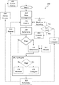
- FIG. 2 is a flowchart illustrating embodiments of a method 200 in a control unit for configuration in a wireless communication system.
- the communication system has a network architecture including a layered structure, for example according to the layered structured illustrated in FIG. 1 .
- Virtual network instances for example in the form of network slice instances, are created, configured, re-configured and terminated using a virtual network management function, such as a network slice management function, in relation to a network state.
- the network state may indicate a number of requests for a service category and the service category may be mapped to a virtual network instance.
- the control unit in which the method is performed may be an embodiment of a control unit 400 illustrated in FIG. 4 and may be included in an embodiment of a network node 500 illustrated in FIG. 5 .
- An embodiment of the method 200 illustrated in FIG. 2 comprises mapping 210 a service category to a virtual network instance based on service requirements of the service category.
- the service category may for example be one of the service types enhanced mobile broadband (eMBB), ultra-reliable low latency communications (URLLC), and massive IoT (mMTC).
- the virtual network instance has a first virtual network instance configuration for a current time interval.
- the first virtual network instance configuration defines a first allocation of resources in a plurality of network layers, such as the network layers 110 , 120 , 130 in FIG. 1 .
- the resources allocated in the different network layers of the plurality of network layers will depend on the network layer.
- a virtual network instance is a network slice instance, NSI.
- the plurality of network layers comprises a radio layer, cloud layers, and transport layers.
- Allocation of resources in the plurality of network layers comprises also allocation of resources in connections 114 , 126 between network components in the plurality of network layers 110 , 120 , 130 .
- a network state in a next time interval is predicted 220 .
- the prediction may be performed in any suitable way.
- the prediction is performed 222 using a machine learning, ML, algorithm.
- the network state may specify dynamic properties that are relevant to virtual network instance configuration.
- predicting 220 comprises predicting a number of requests of the service category in the next time interval.
- predicting 220 a network states comprises predicting a channel condition in the next time interval.
- the predicted performance degradation is in relation to a performance indicator of the service category.
- the performance indicator may relate to a performance parameter for which there are specific requirements for the service category.
- the predicted performance degradation is in relation to one of peak data rate, average data rate, peak spectral efficiency, average spectral efficiency, control plane latency, user plane latency, interrupt at handover, reliability, connection density, mobility, maximum number of digital units needed for requests of the service category, transport layer consumed capacity per service category, and energy of requests of the service category.
- a second virtual network instance configuration for the next time interval is determined 240 .
- the determining 240 of the second virtual network instance configuration is performed on condition that there is a predicted performance degradation in the next time interval in relation to at least one network layer of the plurality of network layers.
- the second virtual network instance configuration defines an adapted second allocation of resources in the plurality of network layers. The adapted second allocation of resources at least partly compensates for the predicted performance degradation in the next time interval in relation to the at least one network layer of the plurality of network layers.
- a second virtual network instance configuration for the next time interval defining an adapted second allocation of resources may include creating further virtual network instances and/or changing the allocation of resources in the plurality of network layers for existing virtual network instances.
- determining 240 a second virtual network instance configuration comprises allocating 242 , based on the predicted performance degradation in relation to the at least one network layer of the plurality of network layers, additional resources in a different network layer of the plurality of network layers than the at least one network layer of the plurality of network layers. Allocating 242 additional resources at least partly compensates for the predicted performance degradation in the next time interval in the at least one network layer of the plurality of network layers.
- the virtual network instance is configured 250 based on the first network instance configuration or the second network instance configuration for the next time interval.
- configuring 250 the virtual network instance comprises configuring 252 the virtual network instance based on the second network instance configuration for the next time interval on condition that there is a predicted performance degradation in the next time interval in relation to at least one network layer of the plurality of network layers.
- configuring 250 the virtual network instance further comprises maintaining 254 the first network instance configuration for the virtual network instance for the next time interval on condition that there is no predicted performance degradation in the next time interval in relation to at least one network layer of the plurality of network layers.
- an actual network state in the next time interval is determined 260 .
- the actual network state may be determined 260 by measuring particular dynamic properties of the network during the next time interval, such as at least one of measuring a number of requests of a service category and measuring a channel status.
- the determined actual network state in the next time interval and the predicted network state for the next time interval are compared 270 .
- compensating 280 for prediction errors is performed. For example, if the actual network state shows that a number of requests of the service category in the next time interval is higher than predicted, more resources may be allocated to compensate 280 for the prediction error.
- the actual network state shows that a number of requests of the service category in the next time interval is lower than predicted, some resources may be released to compensate 280 for the prediction error.
- the procedure may be repeated 290 starting with a new prediction 220 of a network state for a new time interval following the now predicted next time interval.
- the machine learning algorithm may be based on collected history 282 indicating values of selected input parameters for a current time interval and a determined 260 actual network state in a next time interval. For each time the procedure is repeated 290 , the determined actual state and values of selected input parameters are added 284 to history.
- prediction 220 of a network state in a next time period comprises prediction of a number of requests for a service category for the next time period, such as for the next y seconds.
- an example embodiment using machine learning 222 by means of a neural network can be used.
- An example of such an embodiment will be described in the following without loss of generality of type of method possible to use for prediction.
- an alternative approach would be to use a moving average window based on requests made for the service category historically. Such an alternative solution would at least work if the dataset is deprived of enough outliers. However, it may to some extent be limited since it will not take into consideration other aspects that would, at least for some situations, achieve more accurate predictions.
- a linear regression neural network is built specifically trained for the service category. Similar neural networks may be built specifically trained for each service category of a set of service categories. The neural networks would then share the same structure but they will be trained on different datasets which will be specific to each service category.
- a structure of the model is as follows.
- a first layer contains as many neurons as the input parameters we are interested in.
- the following ( 9 input parameters) may be considered:
- the algorithm would be performed using a set of neural networks which share the same structure but each service category is trained on a different dataset which is specific to the service category.
- prediction 220 of a network state in a next time period comprises prediction of a channel condition of a channel for the next time period, such as for the next y seconds, and used to anticipate a performance degradation.
- a linear regression neural network is built specifically trained for the channel. Similar neural networks may be built specifically trained for each of a set of channels. The neural networks would then share the same structure but they will be trained on different datasets which will be specific to each channel.
- a structure of the model is as follows.
- a first layer contains as many neurons as the input parameters we are interested in.
- the following (x parameters) may be considered:
- the channel condition prediction can be combined with the prediction of number of request of a service category. Such a combination is used to determine if there is a predicted performance degradation.
- prediction 220 of a network state in a next time period comprises prediction of a number of requests for a service category for the next time period, such as for the next y seconds.
- the predicted network state in the next time interval results in a predicted performance degradation in the next time interval in relation to at least one network layer of the plurality of network layers.
- the performance degradation may for example be in relation to a performance indicator of the service category.
- the performance indicator may relate to a performance parameter for which there are specific requirements for the service category.
- the predicted performance degradation is in relation to one of peak data rate, average data rate, peak spectral efficiency, average spectral efficiency, control plane latency, user plane latency, interrupt at handover, reliability, connection density, mobility, maximum number of digital units needed for requests of the service category, transport layer consumed capacity per service category, and energy of requests of the service category.
- a second virtual network instance configuration for the next time interval is determined 240 .
- the second virtual network instance configuration defines an adapted second allocation of resources in the plurality of network layers.
- the adapted second allocation of resources at least partly compensates for the predicted performance degradation in the next time interval in relation to the at least one network layer of the plurality of network layers.
- the compensation may comprise allocating 242 additional resources in a different network layer of the plurality of network layers than the at least one network layer of the plurality of network layers for which predicted performance degradation has been determined.
- Allocating 242 additional resources at least partly compensates for the predicted performance degradation in the next time interval in the at least one network layer of the plurality of network layers.
- Determining 240 a second virtual network instance configuration defining an adapted second allocation of resources in the plurality of network layers may comprise re-configuring virtual network instances, such as network slice instances. Such a re-configuration may comprise:
- determining 230 of a performance degradation is made in relation to user plane latency and energy of request of the service category.
- a model that acts as orchestration scheme for all network parameters i.e. radio access network (RAN) parameters (e.g., modulation and coding scheme (MCS), PRB, number of radio-subframes, etc.), cloud processing & transporting parameters (e.g. number of vCPUs, location of processing, number of optical frames, etc.), and a targeted key performance indicator (KPI) for the service category in relation to the user plane latency and energy of request of the service category.
- MCS modulation and coding scheme
- KPI targeted key performance indicator
- Equation 1 provides a metric for the energy per requested service category. Description of the symbols of the following equations are found in Table 1.
- the four components (terms) of the above energy per request of the service category metric (KPI) includes:
- S u Split option allocated to request of the service category M u Modulation index assigned to request of the service category.
- R u Resource block allocated to request of the service category.
- ⁇ Tx UE Energy density per PRB of radio transmission which is different than the static energy of the radio transmission.
- N rsf Number of RSFs needed to deliver the request of the service category.
- T rsf T of Time of a radio sub-frame and optical frame.
- R T Total bandwidth that is used by all services in RU.
- X ec X cc Scaling factor that shows the amount of extra vCPUs.
- D prc Delay of communication processing.
- D N rsf D N of Delay of radio sub-frames, optical frames.
- N sc rb Number of sub-carriers in a resource block.
- N sym sf Number of symbols in a radio sub-frame.
- V s Requested content (not only per radio sub-frame) volume (in bits).
- V s (S u R u M u ) Data volume needed to be transferred from CC to EC. (As a result of the selected split Su it is per radio subframe.)
- C rsf cc,z (S u , R u , M u ) Amount of processing complexity needed per radio subframe at the CC.
- Equation 2 provides a metric for the user plane latency per request of the service category.
- D T ( Z ) D prc,z ( S u ,R u ,M u )+ D N rsf ( R u ,M u )+ D N of ( S u ,R u ,M u )+ D cnst Equation 2
- the four components (terms) breakdown of the above user plane latency per request of the services category metric (KPI) includes:
- the denominator of the first term is the central cloud's 132 equipment capability times the number of vCPUs
- the numerator of the second term is a needed processing at edge cloud 122 per request of the service category
- the denominator of the second term is the edge clouds 122 equipment capability times number of vCPUs.
- the denominator of the first factor is the size of data that can be accommodated by one radio subframe, and the second factor a radio subframe duration.
- the denominator of the first factor is the size of the optical frame
- the second factor an optical frame duration
- degraded delay by reducing M u can be compensated for via changing communication function processing allocation in the central cloud 132 of the central cloud layer 130 and edge cloud 122 of the edge cloud layer 120 .
- One of the cloud parameters is S u , which is equal to 1 when all processing functions are allocated at the central cloud 132 of the central cloud layer 130 and equal to 9 when all functions are allocated in the edge cloud 122 of the edge cloud layer 120 .
- S u is equal to 1 when all processing functions are allocated at the central cloud 132 of the central cloud layer 130 and equal to 9 when all functions are allocated in the edge cloud 122 of the edge cloud layer 120 .
- the network has to reduce M u , from 6 to 4 in a next time interval, to ensure certain reliability, e.g.
- a network slice instance should be created with optimal configurations in relation to allocation of resources in each layer of the plurality of network layers 110 , 120 , 130 . This is achieved in two steps. The first step is to define what an optimal configuration is given the predicted number of requests for the service type has been determined. The second step is to enforce this configuration by sending messages to the different network and infrastructure as a service (IAAS) components.
- IAAS a service
- vCPUs Once the expected number of vCPUs is computed for the central cloud 132 and the edge cloud 122 , we can include them into the network slice instance which is a collection of all desired values expected from each network element to have.
- These parameters are provided from an operator 310 as input to a createNetworkSlice( ) function 312 for creation of a network slice instance as illustrated in the sequence diagram in FIG. 3 . They will be communicated by way of a network slice management function (NSMF) node 320 (such as a network node 500 illustrated in FIG.
- NSMF network slice management function
- a request for the purposes of creating a network slice instance is pushed from the operator 310 to the NSMF node 320 which would then classify which services (such as video, augmented reality, virtual reality, audio, VoIP, email, synching, message, data storage etc.) are needed based on the given request and then predict (e.g. a number of requests of a service category) and materialize the prediction by performing resource allocation using different orchestrators 330 , 340 , 350 in the Transport Layer, Radio Access Network Layer and also in the Cloud layer. Deltas between allocations can exist and as such are moved on to a different orchestrator to compensate for the absence of resources.
- services such as video, augmented reality, virtual reality, audio, VoIP, email, synching, message, data storage etc.
- a wantedState indication 322 indicating a wanted state is sent from the NSMF node 320 to the TransportLayerOrchestrator 330 .
- the wanted state is checked in a check(wantedState) function 332 and available resources are allocated in an allocateResources( ) function 334 . If all wanted resources are not available and cannot be allocated, the available resources are allocated and the difference between the wanted resources and the allocated resources are indicated as a delta1 value 336 from the TransportLayerOrchestrator 330 to the NSMF node 320 .
- the delta1 value 336 is sent from the NSMF node 320 to the RANOrchestrator 340 .
- the wanted state is checked in a check(wantedState+delta1) function 342 and available resources are allocated in an allocateResources( ) function 344 .
- the difference between the wanted resources and the available allocated resources are indicated as a delta1 value 346 from the RANOrchestrator 340 to the NSMF node 320 .
- a wantedState+delta2 indication 326 indicating a wanted state including also the difference between the wanted resources and the available allocated resources from the RANOrchestrator 340 , i.e.
- the delta1 value 346 is sent from the NSMF node 320 to the CloudOrchestrator 350 .
- the wanted state is checked in a check(wantedState+delta2) function 352 and available resources are allocated in an allocateResources( ) function 354 .
- the difference between the wanted resources and the available allocated resources are indicated as a delta3 value 356 from the CloudOrchestrator 330 to the NSMF node 320 .
- FIG. 4 is a block diagram illustrating embodiments of a control unit 400 which may incorporate at least some of the example embodiments discussed above.
- the control unit 400 may comprise processing circuitry 410 .
- the processing circuitry 410 may be any suitable type of computation unit, e.g. a microprocessor, digital signal processor (DSP), field programmable gate array (FPGA), or application specific integrated circuit (ASIC) or any other form of circuitry. It should be appreciated that the processing circuitry need not be provided as a single unit but may be provided as any number of units or circuitry.
- the control unit 400 may further comprise at least one memory unit or circuitry 420 that may be in communication with the processing circuitry 410 .
- the memory 420 may be configured to store executable program instructions 430 .
- the memory 420 may be any suitable type of computer readable memory and may be of volatile and/or non-volatile type.
- FIG. 4 is a block diagram illustrating embodiments of a control unit 400 for configuration in a wireless communication system.
- the communication system has a network architecture including a layered structure, for example according to the layered structured illustrated in FIG. 1 .
- Virtual network instances for example in the form of network slice instances, are created, configured, re-configured and terminated using a virtual network management function, such as a network slice management function, in relation to a network state.
- the network state may indicate a number of requests for a service category and the service category may be mapped to a virtual network instance.
- the memory 420 contains instructions 430 executable by the processing circuitry 410 , whereby the embodiment of the control unit 400 is operative to perform embodiments of the method illustrated in FIG. 2 and described hereinabove.
- FIG. 5 is a block diagram illustrating embodiments of a network node 500 for configuration in a wireless communication system.
- the network node 500 comprises an embodiment of a control unit 400 illustrated in FIG. 4 .
- the network node comprises a control unit 400 .
- the control unit 400 comprises processing circuitry 410 and memory 420 which contains instructions 430 executable by the processing circuitry 410 , whereby the control unit 400 is operative to perform embodiments of the method illustrated in FIG. 2 and described hereinabove.
- control unit 400 in the embodiments of the network node 500 illustrated in FIG. 5 need not be an included separate hardware unit.
- the control unit 400 may be a logical unit of the network node 500 , which may be implemented in software, where the processing circuitry 410 , the memory 420 and the instructions 430 are comprised in the control unit 400 in a logical sense.
- Embodiments may be implemented in a computer program, comprising instructions 430 which, when executed by processing circuitry 410 , cause the processing circuitry 410 to perform the method of the disclosure.
- Embodiments may be implemented in a computer program product 420 having stored thereon a computer program comprising instructions 430 which, when executed by processing circuitry 410 , cause the processing circuitry 410 to perform the method of the disclosure.
- FIG. 1 comprises some operations which are illustrated comprised in solid line boxes and some operations which are illustrated comprised in dashed line boxes.
- the operations which are comprised in solid line boxes are operations which are comprised in the broadest example embodiment.
- the operations which are comprised in dashed line boxes are example embodiments which may be comprised in, or a part of, or are further operations which may be taken in addition to the operations of the broader example embodiment. It should be appreciated that these operations need not be performed in any specific order unless otherwise specified. Furthermore, it should be appreciated that not all of the operations need to be performed.
- the example operations may be performed in any order and in any combination unless otherwise specified.
- FIG. 1 may be performed simultaneously for any number of services or service categories in the wireless communications network.
- the functions or steps noted in the blocks can occur out of the order noted in the operational illustrations.
- two blocks shown in succession can in fact be executed substantially concurrently or the blocks can sometimes be executed in the reverse order, depending upon the functionality/acts involved.
- the functions or steps noted in the blocks can according to some aspects of the disclosure be executed continuously in a loop.
- gNB could be considered as device 1 and “UE” as device 2 , and these two devices communicate with each other over some radio channel.
- UE could be considered as device 1 and “UE” as device 2 , and these two devices communicate with each other over some radio channel.
- example embodiments focus on wireless transmissions in the downlink, it should be appreciated that the example embodiments are equally applicable in the uplink.
- a “UE” as the term may be used herein, is to be broadly interpreted to include a radiotelephone having ability for Internet/intranet access, web browser, organizer, calendar, a camera (e.g., video and/or still image camera), a sound recorder (e.g., a microphone), and/or global positioning system (GPS) receiver; a personal communications system (PCS) user equipment that may combine a cellular radiotelephone with data processing; a personal digital assistant (PDA) that can include a radiotelephone or wireless communication system; a laptop; a camera (e.g., video and/or still image camera) having communication ability; and any other computation or communication device capable of transceiving, such as a personal computer, a home entertainment system, a television, etc.
- a device may be interpreted as any number of antennas or antenna elements.
- UE is a non-limiting term which means any wireless device, terminal, or node capable of receiving in DL and transmitting in UL (e.g. PDA, laptop, mobile, sensor, fixed relay, mobile relay or even a radio base station, e.g. femto base station).
- UL e.g. PDA, laptop, mobile, sensor, fixed relay, mobile relay or even a radio base station, e.g. femto base station.
- a cell is associated with a radio node, where a radio node or radio network node or gNB used interchangeably in the example embodiment description, comprises in a general sense any node transmitting radio signals used for measurements, e.g., gNB, eNodeB, macro/micro/pico base station, home eNodeB, relay, beacon device, or repeater.
- a radio node herein may comprise a radio node operating in one or more frequencies or frequency bands. It may be a radio node capable of CA. It may also be a single- or multi-RAT node.
- a multi-RAT node may comprise a node with co-located RATs or supporting multi-standard radio (MSR) or a mixed radio node.
- a computer-readable medium may include removable and non-removable storage devices including, but not limited to, Read Only Memory (ROM), Random Access Memory (RAM), compact discs (CDs), digital versatile discs (DVD), etc.
- program modules may include routines, programs, objects, components, data structures, etc. that perform particular tasks or implement particular abstract data types.
- Computer-executable instructions, associated data structures, and program modules represent examples of program code for executing steps of the methods disclosed herein. The particular sequence of such executable instructions or associated data structures represents examples of corresponding acts for implementing the functions described in such steps or processes.
Landscapes
- Engineering & Computer Science (AREA)
- Computer Networks & Wireless Communication (AREA)
- Signal Processing (AREA)
- Artificial Intelligence (AREA)
- Computer Vision & Pattern Recognition (AREA)
- Databases & Information Systems (AREA)
- Evolutionary Computation (AREA)
- Medical Informatics (AREA)
- Software Systems (AREA)
- Quality & Reliability (AREA)
- Mobile Radio Communication Systems (AREA)
Abstract
Description
-
- 1. Service categories and corresponding required delay
- 2. Priority of each service category among the set of service categories
- 3. Time, e.g. in second, minutes, hours, and day
- 4. Events in relevant location and time (e.g. sport event, concert etc.)
- 5. Channel status information per UE (e.g., amplitudes, channel delay spread, channel phase, etc.)
- 6. Location of cells
- 7. Environmental elements (e.g. season, natural events, humidity, earthquakes, buildings structure and materials etc.)
- 8. Bandwidth available per cell per UE
- 9. Base station maintenance condition (e.g. latest maintenance data, age of site, and technology)
-
- Obtain log (preferably large) of datasets that classify the traffic demand for the service category. Datasets include for example bits per second, signal strength, radio channel information, service requirements (bandwidth, processing cycles, etc.).
- Identify the associated location (remote RU, gNB-DU).
- Extract and remove the unusual data from the raw dataset.
- Apply sliding window moving average on the service category dataset. This reduces the high fluctuation in the data, e.g. to reduce unnecessary creation of virtual network instances.
- Decide input and output parameters. For example input parameters may be time series, events in the neighbourhood, current measurements of traffic, cell characteristics, antenna number, power consumption, maintenance needs of a site and neighbour sites. See further above. Output parameters may for example be predicted traffic and bits per second for the service category in all sites.
- Decide on the training, validation and testing number of requests.
- Decide and apply the training and prediction too. For this purpose, Levenberg-Marquardt optimization may be used to train the neural network agent and later predict the future data.
- Convert the predicted output to number of requests for the service category
-
- 1. Time stamp
- 2. Radio sub-frame size
- 3. UE mobility
- 4. UE position
- 5. Environment and surrounding building
- 6. Number of antenna
- 7. Multiple connectivity.
-
- Changing UE radio parameters such as modulation index (MI), transmission (Tx) power, physical resource blocks (PRB), radio access technology (RAT).
- Changing allocation of number of virtual central processing units (vCPUs) per virtual network instance.
- Changing priority of accessing transport network for each virtual network instance.
- Changing encryption technique.
-
- 1. Central Cloud (computation+switches+optical)
- 2. Edge Cloud (computation+optical+mmWave)
- 3. Remote Unit (RF analog component+number of radio sub-frames (RSF) related+mmWave)
- 4. UE (RF analog+number of RSF)
| TABLE 1 | |
| Symbol | Description |
| Su | Split option allocated to request of the service category. |
| Mu | Modulation index assigned to request of the service category. |
| Ru | Resource block allocated to request of the service category. |
| Elc, Ees, Eonu, Eosw | Energy density of line card (LC), ethernet switch (ES), optical network |
| unit (ONU), optical switch (OSW) (joule per bit). | |
| Vs |
Volume of bits per request of the service category and split Su 1. |
| Vs |
Volume of bits per request of the service category when Su = 9 2. |
| Edu cc | Energy density of DU at central cloud (CC). |
| Cu cc,z or Cu ec,z | Processing complexity at CC or edge cloud (EC) for downlink (DL) or |
| uplink (UL) of request of the service category. | |
| Efcc, EFec, Efru | Efficiency of equipment at CC, EC, and RU. |
| ηprc ec | Processing efficiency of processors at EC 3 . |
| ηpw ec | Power efficiency of processors in EC. |
| EmWT and EmWR | Energy density of mmWave transmitter and receiver 4. |
| PAng | Power consumption of analogue devices at RU. |
| PAng (UE) | Power consumption of analogue devices at the UE. |
| ρTx UE | Energy density per PRB of radio transmission, which is different than |
| the static energy of the radio transmission. | |
| Nrsf | Number of RSFs needed to deliver the request of the service category. |
| Trsf , Tof | Time of a radio sub-frame and optical frame. |
| RT | Total bandwidth that is used by all services in RU. |
| ρTx | Energy density of radio transmission per a resource block. |
| CEq cc | Equipment processing capability at CC. |
| Xec, Xcc | Scaling factor that shows the amount of extra vCPUs. |
| DT | End to end delay from CC to user. |
| Dprc | Delay of communication processing. |
| DN |
Delay of radio sub-frames, optical frames. |
| Dcnst | Constant delay induced from several equipments. |
| Nsc |
Number of sub-carriers in a resource block. |
| Nsym |
Number of symbols in a radio sub-frame. |
| Vs | Requested content (not only per radio sub-frame) volume (in bits). |
| Vs(SuRuMu) | Data volume needed to be transferred from CC to EC. (As a result of |
| the selected split Su it is per radio subframe.) | |
| Crsf cc,z (Su, Ru, Mu) | Amount of processing complexity needed per radio subframe at the CC. |
| Crsf ec,z (Su, Ru, Mu) | Amount of processing complexity needed per radio subframe at the EC. |
| Oprb | Overhead introduced by communication protocol. |
| Sof(| |
Amount of bits that can be accommodated by the optical frame divided |
| by | |
|
| usage of TWDM-PON. | |
| 1 Vs |
|
| 2 Vs |
|
| 3 ηprc ec is the processing efficiency of the EC’s processors to those in CC. | |
| 4 EmWT and EmWR include static and dynamic parts. | |
D T(Z)=D prc,z(S u ,R u ,M u)+D N
-
- 1. Accumulative user plane latency for the service category induced via processing and is a function of processing location (Se) (which decide number of vCPUs needed at each location), PRB (Ru), and modulation index (Mu), etc.
- 2. Accumulative user plane latency for the service category induce via number of RSF per services and is a function of Ru and Mu, etc.
- 3. Accumulative user plane latency for the service category induce via optical fibre frames, and is a function of Su (which decide number of vCPUs needed at each location), Ru, and Mu.
- 4. Constant user plane latency induced via switches, optical switches, mmWave point-2-point communication, etc.
-
- 1. Number of vCPUs
- 2. Radio Modulation Index
- 3. Number of Physical Resource Block
-
- 4. Optical Technology (in-term of optical frame size and duration)
- 5. Radio technology, in terms of radio subframe (or mini-slot) size and duration.
- 6. Processing Equipment Capability (at
central cloud 132 and edge cloud 122). - 7. Power and processing efficiencies between
central cloud 132 andedge cloud 122 andUE 142. - 8. Transmission power (hence amplifier type)
- 9. Switches and transport layer speed
Claims (18)
Applications Claiming Priority (1)
| Application Number | Priority Date | Filing Date | Title |
|---|---|---|---|
| PCT/EP2019/055757 WO2020177869A1 (en) | 2019-03-07 | 2019-03-07 | Method, control unit and network node for configuration in a wireless communication system |
Publications (2)
| Publication Number | Publication Date |
|---|---|
| US20220150131A1 US20220150131A1 (en) | 2022-05-12 |
| US11411834B2 true US11411834B2 (en) | 2022-08-09 |
Family
ID=65763440
Family Applications (1)
| Application Number | Title | Priority Date | Filing Date |
|---|---|---|---|
| US17/435,183 Active US11411834B2 (en) | 2019-03-07 | 2019-03-07 | Method, control unit and network node for configuration in a wireless communication system |
Country Status (3)
| Country | Link |
|---|---|
| US (1) | US11411834B2 (en) |
| EP (1) | EP3935787B1 (en) |
| WO (1) | WO2020177869A1 (en) |
Families Citing this family (5)
| Publication number | Priority date | Publication date | Assignee | Title |
|---|---|---|---|---|
| US20240314046A1 (en) * | 2021-02-02 | 2024-09-19 | Nippon Telegraph And Telephone Corporation | Control apparatus, control method and program |
| US11853190B2 (en) | 2021-08-27 | 2023-12-26 | Dish Wireless L.L.C. | Dynamic allocation and use of network functions processing resources in cellular networks |
| CN116302301A (en) * | 2021-12-21 | 2023-06-23 | 戴尔产品有限公司 | Time division control of Virtual Local Area Networks (VLANs) to accommodate multiple virtual applications |
| WO2024063678A1 (en) * | 2022-09-19 | 2024-03-28 | Telefonaktiebolaget Lm Ericsson (Publ) | Determining a configuration of a wireless network |
| US20250261046A1 (en) * | 2024-02-14 | 2025-08-14 | T-Mobile Innovations Llc | Geolocation-based network slice allocations for dynamic edge computing resource management |
Citations (16)
| Publication number | Priority date | Publication date | Assignee | Title |
|---|---|---|---|---|
| US20080086731A1 (en) | 2003-02-04 | 2008-04-10 | Andrew Trossman | Method and system for managing resources in a data center |
| US20080134194A1 (en) | 2004-08-13 | 2008-06-05 | Utstarcim Telecom Co., Ltd. | Method for Dynamic Resource Allocation in Centrailized Base Stations |
| CN103401929A (en) | 2013-08-05 | 2013-11-20 | 北京邮电大学 | Self-adaptive networking method based on baseband with large-scale processing ability and business |
| US9430280B1 (en) * | 2013-02-11 | 2016-08-30 | Amazon Technologies, Inc. | Task timeouts based on input data characteristics |
| US20160373941A1 (en) | 2015-06-18 | 2016-12-22 | International Business Machines Corporation | Reconfiguring a Mobile Network Based on Cellular Network State Information |
| US20180203739A1 (en) * | 2017-01-19 | 2018-07-19 | International Business Machines Corporation | Dynamic resource allocation with forecasting in virtualized environments |
| WO2019025944A1 (en) | 2017-07-31 | 2019-02-07 | Telefonaktiebolaget Lm Ericsson (Publ) | Integrated method for automating enforcement of service level agreements for cloud services |
| US10270644B1 (en) * | 2018-05-17 | 2019-04-23 | Accenture Global Solutions Limited | Framework for intelligent automated operations for network, service and customer experience management |
| US20190159048A1 (en) * | 2017-11-21 | 2019-05-23 | At&T Intellectual Property I, L.P. | Network reconfiguration using genetic algorithm-based predictive models |
| US20190318026A1 (en) * | 2018-04-17 | 2019-10-17 | International Business Machines Corporation | Resource condition correction using intelligently configured dashboard widgets |
| US20190363950A1 (en) * | 2018-05-25 | 2019-11-28 | At&T Intellectual Property I, L.P. | Ai-enabled adaptive tca thresholding for sla assurance |
| US20190384790A1 (en) * | 2016-02-05 | 2019-12-19 | Sas Institute Inc. | Staged training of neural networks for improved time series prediction performance |
| US20200042212A1 (en) * | 2018-07-31 | 2020-02-06 | Kaminario Technologies, Ltd. | Generation, validation and implementation of storage-orchestration strategies |
| US20200076520A1 (en) * | 2018-08-31 | 2020-03-05 | At&T Intellectual Property I, L.P. | System and Method for Throughput Prediction for Cellular Networks |
| US20200252271A1 (en) * | 2019-01-31 | 2020-08-06 | EMC IP Holding Company LLC | Consumption-Based Elastic Deployment And Reconfiguration Of Hyper-Converged Software-Defined Storage |
| US20210160147A1 (en) * | 2018-08-06 | 2021-05-27 | Apple Inc. | Management data analytical kpis for 5g network traffic and resource |
-
2019
- 2019-03-07 WO PCT/EP2019/055757 patent/WO2020177869A1/en not_active Ceased
- 2019-03-07 EP EP19710646.1A patent/EP3935787B1/en active Active
- 2019-03-07 US US17/435,183 patent/US11411834B2/en active Active
Patent Citations (16)
| Publication number | Priority date | Publication date | Assignee | Title |
|---|---|---|---|---|
| US20080086731A1 (en) | 2003-02-04 | 2008-04-10 | Andrew Trossman | Method and system for managing resources in a data center |
| US20080134194A1 (en) | 2004-08-13 | 2008-06-05 | Utstarcim Telecom Co., Ltd. | Method for Dynamic Resource Allocation in Centrailized Base Stations |
| US9430280B1 (en) * | 2013-02-11 | 2016-08-30 | Amazon Technologies, Inc. | Task timeouts based on input data characteristics |
| CN103401929A (en) | 2013-08-05 | 2013-11-20 | 北京邮电大学 | Self-adaptive networking method based on baseband with large-scale processing ability and business |
| US20160373941A1 (en) | 2015-06-18 | 2016-12-22 | International Business Machines Corporation | Reconfiguring a Mobile Network Based on Cellular Network State Information |
| US20190384790A1 (en) * | 2016-02-05 | 2019-12-19 | Sas Institute Inc. | Staged training of neural networks for improved time series prediction performance |
| US20180203739A1 (en) * | 2017-01-19 | 2018-07-19 | International Business Machines Corporation | Dynamic resource allocation with forecasting in virtualized environments |
| WO2019025944A1 (en) | 2017-07-31 | 2019-02-07 | Telefonaktiebolaget Lm Ericsson (Publ) | Integrated method for automating enforcement of service level agreements for cloud services |
| US20190159048A1 (en) * | 2017-11-21 | 2019-05-23 | At&T Intellectual Property I, L.P. | Network reconfiguration using genetic algorithm-based predictive models |
| US20190318026A1 (en) * | 2018-04-17 | 2019-10-17 | International Business Machines Corporation | Resource condition correction using intelligently configured dashboard widgets |
| US10270644B1 (en) * | 2018-05-17 | 2019-04-23 | Accenture Global Solutions Limited | Framework for intelligent automated operations for network, service and customer experience management |
| US20190363950A1 (en) * | 2018-05-25 | 2019-11-28 | At&T Intellectual Property I, L.P. | Ai-enabled adaptive tca thresholding for sla assurance |
| US20200042212A1 (en) * | 2018-07-31 | 2020-02-06 | Kaminario Technologies, Ltd. | Generation, validation and implementation of storage-orchestration strategies |
| US20210160147A1 (en) * | 2018-08-06 | 2021-05-27 | Apple Inc. | Management data analytical kpis for 5g network traffic and resource |
| US20200076520A1 (en) * | 2018-08-31 | 2020-03-05 | At&T Intellectual Property I, L.P. | System and Method for Throughput Prediction for Cellular Networks |
| US20200252271A1 (en) * | 2019-01-31 | 2020-08-06 | EMC IP Holding Company LLC | Consumption-Based Elastic Deployment And Reconfiguration Of Hyper-Converged Software-Defined Storage |
Non-Patent Citations (2)
| Title |
|---|
| ETSI TR XXX v<0.01> (<Jan. 2018>) Draft Technical Specification, Network Technologies (NTECH); Autonomic network engineering for the self-managing Future Internet (AFI); Impact of Generic Autonomic Network Architecture (GANA) on other paradigms: How GANA integrates with SDN, NFV, E2E Service Orchestration and Big-Data Analytics for Autonomies, 30 pages. |
| International Search Report and Written Opinion of the International Searching Authority, PCT/EP2019/055757, dated Nov. 11, 2019, 11 pages. |
Also Published As
| Publication number | Publication date |
|---|---|
| EP3935787B1 (en) | 2024-06-19 |
| EP3935787A1 (en) | 2022-01-12 |
| US20220150131A1 (en) | 2022-05-12 |
| WO2020177869A1 (en) | 2020-09-10 |
Similar Documents
| Publication | Publication Date | Title |
|---|---|---|
| US11411834B2 (en) | Method, control unit and network node for configuration in a wireless communication system | |
| US10999854B2 (en) | Method and user equipment for predicting available throughput for uplink data | |
| US11546806B2 (en) | Communication system | |
| CN101400130B (en) | Method, system and device for system information block mapping | |
| EP3895467B1 (en) | Network performance prediction of a fixed wireless network | |
| EP2605579A1 (en) | Base station on the basis of orthogonal frequency division multiplexing scheme and interference coordination method thereof | |
| WO2013127294A1 (en) | Implementing interference coordination in wireless network cloud | |
| CN108293200B (en) | Device throughput determination | |
| US12069704B2 (en) | Learned scheduler for flexible radio resource allocation to applications | |
| US11729664B2 (en) | Allocating resources for communication and sensing services | |
| CN117632463A (en) | A method for dividing computing tasks and related devices | |
| Zheng et al. | Joint downlink and uplink edge computing offloading in ultra-dense HetNets | |
| Saad et al. | Federated multi-agent reinforcement learning for resource allocation in nr-v2x mode 2 | |
| EP3228136B1 (en) | Methods and modules for handling channels in a radio spectrum | |
| Belguidoum et al. | Optimization of 5G throughput and latency in non-standalone and standalone mode | |
| CN117835409A (en) | Communication method, system, equipment and medium for low-orbit satellite and terminal | |
| US10397922B2 (en) | Method for allocating time-frequency resources for the transmission of data packets via a frequency selective channel | |
| JPWO2015079948A1 (en) | ALLOCATION METHOD, RADIO COMMUNICATION SYSTEM, ALLOCATION DEVICE, AND PROGRAM THEREOF | |
| US20140185443A1 (en) | Data optimization technique for the exchange of data at the edge of a wireless local area network | |
| US20230162006A1 (en) | Server and agent for reporting of computational results during an iterative learning process | |
| WO2025076680A1 (en) | Core network management of artificial intelligence at user equipment | |
| Chandra et al. | Energy Efficient AoI Minimization in D2D-Assisted Social IoET Networks | |
| CN121463226A (en) | Apparatus, method and computer readable medium for communication | |
| GB2624522A (en) | Methods and Apparatus relating to Beam Management | |
| WO2024218535A1 (en) | Machine learning (ml)-based method for determining a control channel element (cce) aggregation level for a user equipment (ue) in a physical downlink control channel (pdcch) |
Legal Events
| Date | Code | Title | Description |
|---|---|---|---|
| AS | Assignment |
Owner name: TELEFONAKTIEBOLAGET LM ERICSSON (PUBL), SWEDEN Free format text: ASSIGNMENT OF ASSIGNORS INTEREST;ASSIGNORS:ALABBASI, ABDULRAHMAN;VANDIKAS, KONSTANTINOS;SIGNING DATES FROM 20190307 TO 20190311;REEL/FRAME:057342/0145 |
|
| FEPP | Fee payment procedure |
Free format text: ENTITY STATUS SET TO UNDISCOUNTED (ORIGINAL EVENT CODE: BIG.); ENTITY STATUS OF PATENT OWNER: LARGE ENTITY |
|
| STPP | Information on status: patent application and granting procedure in general |
Free format text: NON FINAL ACTION MAILED |
|
| STPP | Information on status: patent application and granting procedure in general |
Free format text: NOTICE OF ALLOWANCE MAILED -- APPLICATION RECEIVED IN OFFICE OF PUBLICATIONS |
|
| STCF | Information on status: patent grant |
Free format text: PATENTED CASE |
|
| AS | Assignment |
Owner name: SAGO STRATEGIC SOLUTIONS LLC, DELAWARE Free format text: ASSIGNMENT OF ASSIGNORS INTEREST;ASSIGNOR:TELEFONAKTIEBOLAGET LM ERICSSON (PUBL);REEL/FRAME:066421/0286 Effective date: 20231215 Owner name: SAGO STRATEGIC SOLUTIONS LLC, DELAWARE Free format text: ASSIGNMENT OF ASSIGNOR'S INTEREST;ASSIGNOR:TELEFONAKTIEBOLAGET LM ERICSSON (PUBL);REEL/FRAME:066421/0286 Effective date: 20231215 |
|
| MAFP | Maintenance fee payment |
Free format text: PAYMENT OF MAINTENANCE FEE, 4TH YEAR, LARGE ENTITY (ORIGINAL EVENT CODE: M1551); ENTITY STATUS OF PATENT OWNER: LARGE ENTITY Year of fee payment: 4 |