US11343541B2 - Signaling for illumination compensation - Google Patents
Signaling for illumination compensation Download PDFInfo
- Publication number
- US11343541B2 US11343541B2 US17/051,269 US201917051269A US11343541B2 US 11343541 B2 US11343541 B2 US 11343541B2 US 201917051269 A US201917051269 A US 201917051269A US 11343541 B2 US11343541 B2 US 11343541B2
- Authority
- US
- United States
- Prior art keywords
- block
- current block
- pixels
- current
- neighboring
- Prior art date
- Legal status (The legal status is an assumption and is not a legal conclusion. Google has not performed a legal analysis and makes no representation as to the accuracy of the status listed.)
- Active
Links
Images


Classifications
-
- H—ELECTRICITY
- H04—ELECTRIC COMMUNICATION TECHNIQUE
- H04N—PICTORIAL COMMUNICATION, e.g. TELEVISION
- H04N19/00—Methods or arrangements for coding, decoding, compressing or decompressing digital video signals
- H04N19/85—Methods or arrangements for coding, decoding, compressing or decompressing digital video signals using pre-processing or post-processing specially adapted for video compression
-
- H—ELECTRICITY
- H04—ELECTRIC COMMUNICATION TECHNIQUE
- H04N—PICTORIAL COMMUNICATION, e.g. TELEVISION
- H04N19/00—Methods or arrangements for coding, decoding, compressing or decompressing digital video signals
- H04N19/10—Methods or arrangements for coding, decoding, compressing or decompressing digital video signals using adaptive coding
- H04N19/169—Methods or arrangements for coding, decoding, compressing or decompressing digital video signals using adaptive coding characterised by the coding unit, i.e. the structural portion or semantic portion of the video signal being the object or the subject of the adaptive coding
- H04N19/17—Methods or arrangements for coding, decoding, compressing or decompressing digital video signals using adaptive coding characterised by the coding unit, i.e. the structural portion or semantic portion of the video signal being the object or the subject of the adaptive coding the unit being an image region, e.g. an object
- H04N19/176—Methods or arrangements for coding, decoding, compressing or decompressing digital video signals using adaptive coding characterised by the coding unit, i.e. the structural portion or semantic portion of the video signal being the object or the subject of the adaptive coding the unit being an image region, e.g. an object the region being a block, e.g. a macroblock
-
- H—ELECTRICITY
- H04—ELECTRIC COMMUNICATION TECHNIQUE
- H04N—PICTORIAL COMMUNICATION, e.g. TELEVISION
- H04N19/00—Methods or arrangements for coding, decoding, compressing or decompressing digital video signals
- H04N19/10—Methods or arrangements for coding, decoding, compressing or decompressing digital video signals using adaptive coding
- H04N19/102—Methods or arrangements for coding, decoding, compressing or decompressing digital video signals using adaptive coding characterised by the element, parameter or selection affected or controlled by the adaptive coding
- H04N19/117—Filters, e.g. for pre-processing or post-processing
-
- H—ELECTRICITY
- H04—ELECTRIC COMMUNICATION TECHNIQUE
- H04N—PICTORIAL COMMUNICATION, e.g. TELEVISION
- H04N19/00—Methods or arrangements for coding, decoding, compressing or decompressing digital video signals
- H04N19/10—Methods or arrangements for coding, decoding, compressing or decompressing digital video signals using adaptive coding
- H04N19/134—Methods or arrangements for coding, decoding, compressing or decompressing digital video signals using adaptive coding characterised by the element, parameter or criterion affecting or controlling the adaptive coding
- H04N19/136—Incoming video signal characteristics or properties
- H04N19/137—Motion inside a coding unit, e.g. average field, frame or block difference
- H04N19/139—Analysis of motion vectors, e.g. their magnitude, direction, variance or reliability
-
- H—ELECTRICITY
- H04—ELECTRIC COMMUNICATION TECHNIQUE
- H04N—PICTORIAL COMMUNICATION, e.g. TELEVISION
- H04N19/00—Methods or arrangements for coding, decoding, compressing or decompressing digital video signals
- H04N19/10—Methods or arrangements for coding, decoding, compressing or decompressing digital video signals using adaptive coding
- H04N19/134—Methods or arrangements for coding, decoding, compressing or decompressing digital video signals using adaptive coding characterised by the element, parameter or criterion affecting or controlling the adaptive coding
- H04N19/157—Assigned coding mode, i.e. the coding mode being predefined or preselected to be further used for selection of another element or parameter
- H04N19/159—Prediction type, e.g. intra-frame, inter-frame or bidirectional frame prediction
-
- H—ELECTRICITY
- H04—ELECTRIC COMMUNICATION TECHNIQUE
- H04N—PICTORIAL COMMUNICATION, e.g. TELEVISION
- H04N19/00—Methods or arrangements for coding, decoding, compressing or decompressing digital video signals
- H04N19/46—Embedding additional information in the video signal during the compression process
-
- H—ELECTRICITY
- H04—ELECTRIC COMMUNICATION TECHNIQUE
- H04N—PICTORIAL COMMUNICATION, e.g. TELEVISION
- H04N19/00—Methods or arrangements for coding, decoding, compressing or decompressing digital video signals
- H04N19/50—Methods or arrangements for coding, decoding, compressing or decompressing digital video signals using predictive coding
- H04N19/503—Methods or arrangements for coding, decoding, compressing or decompressing digital video signals using predictive coding involving temporal prediction
- H04N19/51—Motion estimation or motion compensation
- H04N19/513—Processing of motion vectors
- H04N19/517—Processing of motion vectors by encoding
- H04N19/52—Processing of motion vectors by encoding by predictive encoding
-
- H—ELECTRICITY
- H04—ELECTRIC COMMUNICATION TECHNIQUE
- H04N—PICTORIAL COMMUNICATION, e.g. TELEVISION
- H04N19/00—Methods or arrangements for coding, decoding, compressing or decompressing digital video signals
- H04N19/90—Methods or arrangements for coding, decoding, compressing or decompressing digital video signals using coding techniques not provided for in groups H04N19/10-H04N19/85, e.g. fractals
- H04N19/96—Tree coding, e.g. quad-tree coding
Definitions
- the present disclosure relates generally to video processing.
- the present disclosure relates to signaling of illumination compensation.
- High-Efficiency Video Coding is based on the hybrid block-based motion-compensated DCT-like transform coding architecture.
- the basic unit for compression termed coding unit (CU), is a 2N ⁇ 2N square block, and each CU can be recursively split into four smaller CUs until the predefined minimum size is reached.
- Each CU contains one or multiple prediction units (PUs).
- intra prediction modes use the spatial neighboring reconstructed pixels to generate the directional predictors
- inter prediction modes use the temporal reconstructed reference frames to generate motion-compensated predictors.
- the residual blocks are further transformed and quantized in transform units (TU) and then coded into bitstream.
- TU transform units
- Inter predictions explores the correlations of pixels between frames and can be efficient if the scene are stationary and motion estimation can find similar blocks with similar pixel values in the temporal neighboring frames. However, frames are captured in different lighting conditions. The pixel values between frames may be different even if the content is similar and the scene is stationary.
- Some embodiments of the disclosure provides a video coder that implements illumination compensation.
- the video coder receives a first block of pixels in a first video picture to be coded as a current block, wherein the current block is associated with a motion vector that references a second block of pixels in a second video picture as a reference block.
- the video coder performs inter-prediction for the current block by using the motion vector to generate a set of motion-compensated pixels for the current block.
- the video coder modifies the set of motion-compensated pixels of the current block by applying a linear model that is computed based on neighboring samples of the reference block and of the current block. The neighboring samples are identified based on a position of the current block within a larger block.
- the video coder determines whether to enable illumination compensation mode based on a prediction setting of the current block, and the video coder modifies the current block by applying a linear model when the illumination compensation mode is enabled.
- the illumination compensation mode may be disabled if the current block is not a top-most block or a left-most block of the larger block or CTU. In some embodiments, the illumination compensation mode is turned off when General Bi-prediction (GBi), Bi-directional optical flow (BIO), Sub-PU Temporal Motion Vector Prediction (SPTMVP or ATMVP), Affine mode, Bilateral Template MV Refinement (DMVR), Multi-hypothesis Intra-Merge mode, Multi-hypothesis Merge mode, or Multi-hypothesis Merge+AMVP mode is turned on for the current block.
- GBi General Bi-prediction
- BIO Bi-directional optical flow
- SPTMVP or ATMVP Sub-PU Temporal Motion Vector Prediction
- Affine mode Bilateral Template MV Refinement
- DMVR Bilateral Template MV Refinement
- Multi-hypothesis Intra-Merge mode Multi-hypothesis Merge mode
- Multi-hypothesis Merge+AMVP mode Multi-hypothesis Merge+AMVP mode
- the neighboring samples are identified based on a position of the current block within a larger block.
- the linear model is based on a set of illumination compensation parameters comprising a scaling factor and an offset for a linear model.
- the larger block may include multiple sub-blocks and the current block is a first sub-block. Neighboring pixels of the first sub-block are used as neighboring samples to compute the linear model that is used to modify the current block and other sub-blocks of the larger block. In some embodiments, neighboring pixels of the larger block are sub-sampled and used as the neighboring samples to compute the linear model that is used to modify the current block and other sub-blocks of the larger block.
- the current block may be a CU in a CTU that includes multiple CUs.
- the identified neighboring samples of the current block are derived based on neighboring pixels of the CTU.
- the current block is a prediction unit (PU) and the larger block is a coding unit (CU) that includes a plurality of PUs and has a size that is greater than a threshold.
- the identified neighboring samples of the current block are derived based on neighboring pixels of the CU.
- the identified neighboring samples of the current block are neighboring pixels of the larger block that are vertically or horizontally aligned with the current block.
- the neighboring samples may include neighboring pixels above the larger block and no other pixels when the current block is at a top edge of the larger block but not at a left edge of the larger block.
- the neighboring samples may include neighboring pixels left of the larger block and no other pixels when the current block is at a left edge of the larger block but not at a top edge of the larger block.
- the neighboring samples are computed by using reconstructed pixels of a neighboring block based on prediction pixels and residual pixels when the residual pixels are available and by using the prediction pixels of the neighboring block when the residual pixels are not available.
- the linear model is inherited from a neighboring block of the current block.
- FIG. 1 conceptually illustrates illumination compensation mode according to some embodiments of the disclosure.
- FIG. 2 illustrates deriving NPO offsets for different pixel positions for a Prediction Unit (PU) as the current block.
- PU Prediction Unit
- FIG. 3 a illustrates illumination compensation mode for a current block that is a top-most sub-block of a larger block.
- FIG. 3 b illustrates illumination compensation mode for a current block that is a left-most sub-block of a larger block.
- FIG. 4 illustrates neighboring samples for a current CU that are taken from outside of the current CTU.
- FIG. 5 illustrates a CTU whose L-shape neighbor provide the neighboring samples for a CU in the CTU during illumination compensation mode.
- FIG. 6 illustrates a CU the illumination compensation mode parameters of which are inherited by or shared with other CUs within a CTU.
- FIG. 7 illustrates an example video encoder that implements illumination compensation mode, consistent with some embodiments of the disclosure.
- FIG. 8 illustrates portions of the video encoder that implement illumination compensation mode, consistent with some embodiments of the disclosure.
- FIG. 9 illustrates an example video decoder that implements illumination compensation mode, consistent with some embodiments of the disclosure.
- FIG. 10 illustrates portions of the video decoder that implement illumination compensation mode, consistent with some embodiments of the disclosure.
- FIG. 11 conceptually illustrates a process for performing illumination compensation mode of the current block.
- FIG. 12 conceptually illustrates an electronic system with which some embodiments of the present disclosure are implemented.
- Some embodiments of the disclosure provide a video coder that may implement an illumination compensation mode. Specifically, when encoding or decoding a block of pixels as a current block of pixels to be coded, the video coder may apply a linear model (based on a set of illumination compensation parameters) to inter-predicted (or motion-compensated) pixel values of the current block when the illumination compensation mode is enabled. The linear model is applied to each pixel position of the current block to compensate for changes that are not due to motion, e.g., changes in lighting conditions.
- the video coder receives a first block of pixels in a first video picture to be coded as a current block.
- the current block is associated with a motion vector that references a second block of pixels in a second video picture as a reference block.
- the video coder performs inter-prediction for the current block by using the motion vector to generate a set of motion-compensated pixels for the current block.
- the video encoder may enable or disable illumination compensation mode for the current block based on a particular set of conditions. When illumination compensation is enabled, the video coder may provide a linear model or a set of illumination compensation parameters for the current block and use the linear model or the set of illumination compensation parameters to modify the set of motion-compensated pixels of the current block.
- the linear model may be computed based on neighboring samples that are identified for the current block and the reference block.
- FIG. 1 conceptually illustrates illumination compensation mode according to some embodiments of the disclosure.
- the figure illustrates a block of pixels 100 that is the current block being coded by a video coder.
- the current block 100 is in a first video picture 102 .
- the current block 100 is associated with a motion vector 104 .
- the motion vector 104 references a set of pixels 110 as a reference block in a second video picture 112 .
- a motion compensation module 120 of the video coder Based on the motion vector 104 , a motion compensation module 120 of the video coder performs inter prediction to produce a set of prediction pixels 124 for the current block.
- the set of prediction pixels 124 is added with a set of residual pixels 126 to generate a set of reconstructed pixels 122 for the current block 100 .
- the video coder includes an illumination compensation module 130 that may apply a linear model 132 to modify the pixel values of the motion-compensated current block 122 .
- the linear model 132 may be characterized by a scaling factor and an offset.
- the illumination compensation may modify the pixel value at each pixel position of the motion-compensated current block 122 according to the linear model 132 .
- the modified pixels of the current block 128 , or the luminance compensated current block 128 are stored in the reconstructed picture buffer 160 to be displayed or to be referenced by subsequent blocks and/or video pictures.
- the illumination compensation modifies the pixel values of the motion-compensated current block 122 by applying the linear model 132 to refine the prediction pixels 124 .
- the linear model 132 may be derived dynamically based on the neighboring samples 106 of the current block and neighboring samples 116 of the reference block.
- Neighboring samples of a block generally refer to pixel samples of a L-shape regions (or L-shape template) that are near the top of the block and near the left of the block.
- Video coders in different embodiments may use pixels in different positions relative to the current block as neighboring samples (in other words, different L-shape regions) when determining the linear model for illumination compensation.
- the neighboring samples of a block are taken from pixels immediately to the top and left of the block.
- the current block is a sub-block of a larger block or a CU of a CTU, and the neighboring samples are taken from the neighboring pixels of the larger block or the CTU rather than from the immediate neighboring pixels of the current block.
- the pixels in the L-shape template of the current block and the L-shape template of the reference block are sub-sampled into a particular size. After the sub-sampling, the weighting factor and offset factor of the linear model can be calculated by the sub-sampled L-shape.
- the video coder may use the reconstructed pixels of a neighboring block as neighboring samples to compute the linear model.
- the video coder may use only the prediction pixels of the neighboring block as neighboring samples to compute the linear model if the residual pixels of the neighboring block are not yet available.
- the current block 100 may also inherit its linear model 132 from a neighboring block, e.g., the neighboring block providing the selected merge candidate during merge mode.
- the current block may also retrieve a previously used linear model from a history buffer 170 .
- the video coder may or may not perform illumination compensation for the current block. If the illumination compensation is disabled or bypassed for the current block, the video coder may not compute the linear model for the current block and may not modify the motion-compensated pixels of the current block based on the linear model.
- the video coder may enable or disable illumination compensation based on one or more enabling conditions 150 .
- enabling conditions 150 may include the size of the current block, the position of the current block within a larger block (e.g., the position of the current CU in a CTU), or the configuration settings of other operations related to the current block, e.g., General Bi-prediction (GBi), Bi-directional optical flow (BIO), Sub-PU Temporal Motion Vector Prediction (SPTMVP or ATMVP), Affine mode, Bilateral Template MV Refinement (DMVR), Multi-hypothesis Intra-Merge mode, Multi-hypothesis Merge mode, Multi-hypothesis Merge+AMVP mode, etc.
- the current block may also inherit its illumination compensation settings, including whether to enable illumination compensation mode, from a neighboring block during merge mode.
- the video coder may infer the configuration settings of other operations based on the settings of the illumination compensation mode.
- Video coders in different embodiments may use different types of illumination compensation modes, which may use different linear models or different methods of modifying the current block to compensate for illumination changes.
- illumination compensation modes include: Neighboring-derived Prediction Offset (NPO), whose linear model applies an offset to each pixel position of the current block; and Local Illumination compensation (LIC), whose linear model applies a scaling factor and an offset to each pixel value of the current block.
- NPO Neighboring-derived Prediction Offset
- LIC Local Illumination compensation
- NPO Neighboring-Derived Prediction Offset
- NPO Neighboring-derived Prediction Offset
- NRP neighboring reconstructed pixels
- EMCP extended motion-compensated predictors
- the patterns chosen for NRP and EMCP are N pixels left and M pixels above to the current block and the reference block, respectively, where N and M is a predetermined value.
- the patterns can be of any size and shape and can be decided according to any encoding parameters, such as PU or CU sizes, as long as they are the same for both NRP and EMCP.
- the offset is calculated as the average pixel value of NRP minus the average pixel value of EMCP. This derived offset will be unique over the PU and applied to the whole PU along with the motion-compensated predictors.
- FIG. 2 illustrates deriving NPO offsets for different pixel positions for a PU 200 as the current block.
- the individual offset is calculated as the corresponding pixel in NRP (neighboring pixels of the current block 200 ) minus the corresponding pixel in EMCP (neighboring pixels of a reference PU 210 ).
- the offset values are 6, 4, 2, ⁇ 2 for the above neighboring positions and 6, 6, 6, 6 for the left neighboring positions.
- the offset positions of individual positions of the current block are calculated. Specifically, the derived offset for each position in the current block 200 is calculated as the average of the offsets from the left and above positions. For example, for the left-most position in the top row, offset of 6 is generated by averaging the offset from left (6) and above (6). For the second left-most position in the top row, the offset of 5 is calculated as the average of the offset from the left (6) and above (4).
- the offset for each position can be processed and generated in raster scan order sequentially. Since the neighboring pixels are more highly correlated to the boundary pixels, so do the offsets.
- the offset values are adaptive according to the pixel positions. The derived offsets are adaptive over the PU and applied to each PU position individually along with the motion-compensated predictors.
- LIC Local Illumination Compensation
- LIC is a method of inter prediction that uses neighbor samples of the current block and neighbor samples of a reference block to derive a linear model that includes a scaling factor a and an offset b.
- LIC is enabled or disabled adaptively for each CU.
- a least square error method is employed to derive the parameters a and b by using the neighboring samples of the current block and their corresponding reference samples in a reference picture (i.e., neighboring samples of the reference block).
- a reference picture i.e., neighboring samples of the reference block.
- subsampled (e.g., 2:1 subsampling) neighboring samples of the CU and the corresponding pixels (identified by motion information of the current CU or sub-CU) in the reference picture are used to derive the parameters a and b.
- the LIC parameters are derived and applied for each prediction direction separately.
- the LIC flag is copied from neighboring blocks, in a way similar to motion information copy in merge mode; otherwise, an LIC flag is signaled for the CU to indicate whether LIC applies or not.
- additional CU level rate-distortion (RD) check is performed to determine whether LIC is applied or not for a CU.
- mean-removed sum of absolute difference MR-SAD
- mean-removed sum of absolute Hadamard-transformed difference MR-SATD
- SAD and SATD are used for integer pel motion search and fractional pel motion search, respectively.
- LIC is disabled for the entire picture when there is no obvious illumination change between a current picture and its reference pictures. Histograms of a current picture and every reference picture of the current picture may be calculated at the encoder to identify this situation. If the histogram difference between the current picture and every reference picture of the current picture is smaller than a given threshold, LIC is disabled for the current picture; otherwise, LIC is enabled for the current picture.
- the current block may be a sub-block of a larger block that contains multiple sub-blocks.
- the current block may also be a CU in a larger CTU that contains multiple CUs.
- the current block may also be a Video Processing and Distribution Unit (VPDU) inside a large CU that includes multiple VPDUs.
- VPDU Video Processing and Distribution Unit
- the video coder may use a position constraint for determining whether to enable or disable illumination compensation mode (e.g., LIC, NPO) for the current block. Namely, if the position of the current block within the larger block satisfies the constraint, illumination compensation mode is turned on, otherwise, it is turned off. In some embodiments, illumination compensation mode is turned on when the current CU is at the topmost position inside the current CTU. In some embodiments, illumination compensation mode is turned on when the current CU is at the leftmost position inside current CTU. In some embodiments, illumination compensation mode is turned on when the current CU is on the leftmost position and/or on the topmost position. In some embodiments, when the current block fails the position constraint, the illumination compensation mode is turned off implicitly and that the video encoder does not signal on/off syntax for illumination compensation mode.
- illumination compensation mode e.g., LIC, NPO
- the L-shape template from which the neighboring samples are taken may drop a vertical part or a horizontal part.
- the current CU is a leftmost CU of the current CTU but not a topmost CU of the current CTU (e.g., the starting X coordinate of the CU is equal to starting X coordinate of the current CTU coordinate x but the starting Y coordinate of the current CU is not equal to the starting Y coordinate of the current CTU coordinate)
- the L-shape region from which the neighboring samples are taken may include only the vertical part but not the horizontal part.
- the L-shape region from which the neighboring samples are taken may include only the horizontal part but not the vertical part.
- the reconstructed samples from the CTU row above the current CTU are available in the CTU row buffer for the current pipeline stage.
- using top or left neighboring pixels of the CTU as neighboring samples to compute the linear model for the current CU may reduce the latency.
- FIG. 3 a illustrates illumination compensation mode for a current block that is a top-most sub-block of a larger block.
- the figure illustrates a CU 310 that is in a CTU 300 .
- the CU 310 is a top-most CU of the CTU 300 .
- the CU 310 is not a left-most CU of the CTU 300 .
- the illumination compensation mode is turned on for the CU 310 , since the top edge of the CU 310 touches the top edge of the CTU 300 .
- the neighboring samples used to compute the linear model for the illumination compensation mode includes only the horizontal part of the L-shape, illustrated as region 320 .
- the region 320 does not include pixels neighboring the left edge of the CTU 300 or the CU 310 .
- the CU 310 has a corresponding reference block 311 identified by a MV 315 .
- only the neighboring samples in a region 321 to the top of the reference block 311 is used. Samples to the left of the reference block 311 are not used.
- FIG. 3 b illustrates illumination compensation mode for a current block that is a left-most sub-block of a larger block.
- the figure illustrates a CU 330 that is in a CTU 300 .
- the CU 330 is a left-most CU of the CTU 300 .
- the CU 330 is not a top-most CU of the CTU 300 .
- the illumination compensation mode is turned on for the CU 330 , since the left edge of the CU 330 touches the left edge of the CTU 300 .
- the neighboring samples used to compute the linear model for the illumination compensation mode includes only the vertical part of the L-shape, illustrated as region 340 .
- the region 340 does not include pixels neighboring the top edge of the CTU 300 or the CU 330 .
- the CU 330 has a corresponding reference block 331 identified by a MV 335 .
- When computing the linear model for the CU 330 only the neighboring samples in a region 341 to the left of the reference block 331 is used. Samples above the reference block 331 are not used.
- the L-shape template from which the neighboring samples are taken may be outside of the larger block that includes the current block.
- the neighboring samples may be neighboring pixels of the CTU that are vertically or horizontally aligned with the CU.
- FIG. 4 illustrates neighboring samples for a current CU that are taken from outside of the current CTU.
- illumination compensation mode is performed for a current CU 410 within a CTU 400 .
- the neighboring samples for the current CU 410 for the illumination compensation mode are taken from a “modified” L-shape region 420 , which includes a horizontal part 421 and a vertical part 422 .
- the horizontal part 421 of the L-shape is just outside the current CTU 400 with its horizontal position aligned to the CU 410 .
- the vertical part 422 of the L-shape is also just outside the current CTU 400 with its vertical position aligned with the CU 410 .
- the horizontal part 421 of the L-shape may also be located far outside the current CTU but with its horizontal position aligned to the CU 410 .
- the vertical part 422 of the L-shape may also be located far outside of the current CTU with its vertical position aligned to the CU 410 .
- the CU 410 is inter predicted by a MV 415 that references a reference block 430 .
- the neighboring samples of the reference block 430 are taken from a L-shape region 440 , which includes a horizontal part 441 and a vertical part 442 .
- the L-shape region 440 has the same relative positions that correspond to the L-shape region 420 (i.e., regions 441 and 442 have same relative position from the reference block 430 as the regions 421 and 422 from the CU 410 ).
- the illumination compensation mode uses pixels in the L-shape neighboring region of the CTU to provide the neighboring samples of any CU within CTU.
- FIG. 5 illustrates a CTU 500 whose L-shape neighbor 520 provide the neighboring samples for a CU 510 in the CTU 500 during illumination compensation mode.
- the L-shape neighbor 520 of current CTU 500 is used to derive (based on sub-sampling or a planar-mode similar to the intra mode planar mode) an estimated L-shape neighbor for the current CU's 510 .
- AMV 515 associated with the current CU 510 references a reference block 530 , and the neighboring samples from the L-shape neighbor 540 of the reference block 530 are used to derive the illumination compensation mode parameters (scaling factor and offset of linear model) of the current CU 510 .
- the current block is a sub-block of a larger block that comprises other sub-blocks
- the illumination compensation mode parameters computed for the current block is applicable to other sub-blocks of the larger block.
- an internal CU a CU not touching CTU row top boundary
- the illumination compensation mode parameters scaling factor and offset of linear model
- the illumination compensation linear model of the top-CU is inherited by other CUs in the CTU through merge mode.
- the illumination compensation mode on/off flag as well as the illumination compensation mode parameters may be inherited.
- the top-CU may be configured to not inherit illumination compensation mode parameters but deriving them from top-neighboring pixels of CTU row. Therefore, the top-CU may use top-neighboring pixels of the CTU row to derive accurate illumination compensation mode parameters, and the internal CU may reuse the illumination compensation mode parameters of top-CU by merge mode.
- FIG. 6 illustrates a CU the illumination compensation mode parameters of which are inherited by or shared with other CUs within a CTU.
- the figure illustrates a CTU 600 that includes four CUs 611 - 614 .
- the CU 611 is at the top-left corner of the CTU 600 . In other words, the neighboring pixels immediately adjacent to the top and left of the CTU 600 also immediately adjacent to the top and the left of the CU 611 .
- the pixels in the L-shape region 621 are used as neighboring samples.
- the L-shape region 621 include neighboring pixels immediately adjacent to the top and left of the CTU 600 and the CU 611 .
- the CU 611 is associated with a MV 615 , which references a reference block 631 .
- the pixels in a L-shape region 641 above and to the left of the reference block 631 are used as neighboring samples of the reference block 631 .
- the neighboring samples in the L-shape region 641 and the neighboring samples in the L-shape region 621 are used to determine the illumination compensation mode parameters (or linear model) 650 for the CU 611 .
- the linear model 650 is used to perform illumination compensation for the CU 611 . It is also used to perform illumination compensation for the CUs 612 , 613 , 614 , even though they are not adjacent to the L-shaped region 621 .
- the CUs 612 , 613 , and 614 may inherit linear model 650 from the CU 611 through merge mode, e.g., by selecting a merge candidate that corresponds to the CU 611 .
- a history buffer is used to store the illumination compensation parameters of previously coded CUs. The illumination compensation parameters of a previously coded CU may be retrieved from the History buffer (e.g., 170 ) and used to modify the pixels of the current block.
- the methods of computing illumination compensation mode parameters described above for a CU within a CTU may be used to compute illumination compensation mode parameters for a sub-block within a larger block, and for a VPDU or a PU within a larger CU. For example, if a CU has multiple PUs and each PU has a particular size, then only the first PU of the CU (e.g., the PU at the top-left corner of the CU) uses its neighboring reconstructed samples to derive illumination compensation model parameters. Other PUs in the CU may inherent the model parameters from the first PU.
- the current block is partitioned into multiple sub-blocks, and the illumination compensation mode is executed for each sub-block independently.
- the video coder may use only the prediction pixels of the L-shape template for illumination compensation mode.
- an explicit flag in a bitstream may be used to signal whether illumination compensation mode is enabled or disabled for a current block.
- the illumination compensation mode may also be enabled or disabled based on the position of the current CU in a CTU.
- the illumination compensation mode may also be enabled or disabled based on the size of the current block. For example, in some embodiments, a current CU or PU that is larger than or equal to a certain threshold has illumination compensation mode implicitly turned off.
- configuration settings of other tools or operations related to encoding or decoding the current block are used to determine whether illumination compensation is enabled or disabled for the current block.
- the settings of other inter prediction tools for the current block such as General Bi-prediction (GBi), Bi-directional optical flow (BIO), Sub-PU Temporal Motion Vector Prediction (SPTMVP or ATMVP), Affine mode, Bilateral Template MV Refinement (DMVR), Multi-hypothesis Intra-Merge mode, Multi-hypothesis Merge mode, Multi-hypothesis Merge+AMVP mode may be used to implicitly turn on or off illumination compensation.
- BIO being turned on infers that illumination compensation mode is turned off; GBi being turn on infers that illumination compensation mode is turned off; BIO and GBI being turned on infers that illumination compensation mode is turned off; DMVR being turned on infers that illumination compensation mode is turned off; Multi-hypothesis (Intra-Merge) being turned on infers that illumination compensation mode is turned off.
- the configuration settings of other tools may also be used to infer the setting of the illumination compensation mode. Some combinations of the configuration settings listed above may also be used to infer the setting of the illumination compensation mode.
- other tools or operations related to encoding or decoding the current block are turned off when illumination compensation mode is turned on. Examples include:
- BIO being turned off when illumination compensation mode is turned on; GBi being turned off when illumination compensation mode is turned on; BIO and GBI are turned off when illumination compensation mode is turned on; DMVR is turned off when illumination compensation mode is turned on; Multi-hypothesis Intra-Merge mode and DMVR are turned off when illumination compensation mode is turned on.
- the setting of the illumination compensation mode may also be used to turn on or off some combinations of the above mentioned tools or operations.
- the turning off of the other tools or operations may be implicit (without using bitstream syntax element) or explicit (using bitstream syntax elements).
- the GBi may be implicitly turned off.
- the GBI index syntax may be repurposed for AMVP if illumination compensation mode is turned on. For example, if illumination compensation mode is turned on (by syntax or by merge mode inheritance), the syntax element of Multi-hypothesis Intra-Merge may be saved and inferred to be 0.
- Bi-directional Optical Flow utilizes the assumptions of optical flow and steady motion to achieve the sample-level motion refinement. It is applied only for truly bi-directional predicted blocks, which is predicted from two reference frames and one is the previous frame and the other is the latter frame.
- BIO may utilize one 5 ⁇ 5 window to derive the motion refinement of one sample, so for one N ⁇ N block, the motion-compensated results and corresponding gradient information of one (N+4) ⁇ (N+4) block are required to derive the sample-based motion refinement of current block.
- one 6-Tap gradient filter and one 6-Tap interpolation filter are used to generate the gradient information in BIO.
- Generalized bi-prediction is a weighted bi-prediction technique that allows using different weights for predictors from L0 and L1, respectively, instead of using equal weights. It computes the prediction signal of a block as a weighted average of two motion-compensated prediction blocks using block-level adaptive weights, where the weight values are not restricted to 0.5.
- the video coder may indicate a weight value for GBi by using an index to select a candidate weight from a set of candidate weights.
- a Sub-PU Temporal Motion Vector Prediction (Sub-PU TMVP) mode is applied in the merge mode.
- the current PU is partitioned into many Sub-PUs, and the corresponding temporal collocated motion vectors are identified for each Sub-PU.
- the current PU of size M ⁇ N has (M/P) ⁇ (N/Q) sub-PUs, each sub-PU is of size P ⁇ Q, where M is divisible by P, and N is divisible by Q.
- Step 1 for the current PU, the Sub-PU TMVP mode finds an “initial motion vector”, which is denoted it as vec_init .
- LX L0 or L1
- L0 L1
- L1 L0
- L1 L1
- POC distance closer than L1 L0
- LX assignment can be slice level or picture level.
- a collocated picture searching process is used to find a main collocated picture for all sub-PU in the Sub-PU TMVP mode.
- the main collocated picture is denoted as main_colpic.
- the collocated picture searching process searches the reference picture selected by the first available spatial neighboring block, and then searches all reference picture of current picture. For B-slices, the searching process starts from L0 (or L1), reference index 0, then index 1, then index 2, and so on. If the searching process finishes searching L0 (or L1), it then searches another list. For P-slices, the searching process searches the reference picture selected by the first available spatial neighboring block, and then searches all reference picture of current picture of the list starting from reference index 0, then index 1, then index 2, and so on.
- the collocated picture searching process For each searched picture, the collocated picture searching process performs availability checking for motion information.
- a scaled version of vec_init (denoted as vec_init_scaled) is added to an around-center position of the current PU.
- the added position is then used to check for prediction type (intra/inter) of the searched picture.
- the prediction type is an inter type, then the motion information is available (availability is true). If the prediction type is an intra type, then the motion information is not available (availability is false).
- the searching process completes availability checking, if the motion information is available, then current searched picture is recorded as the main collocated picture. If the motion information is not available, then the searching process proceeds to search next picture.
- the collocated picture searching process performs MV scaling to create the scaled version of vec_init (i.e., vec_init_scaled) when the reference picture of the vec_init is not the current reference picture.
- the scaled version of vec_init is created based on the temporal distances between the current picture, the reference pictures of the vec_init, and the searched reference picture.
- Step 3 For each sub-PU, the Sub-PU TMVP mode finds a collocated picture for reference list 0 and a collocated picture for reference list 1. By definition, there is only one collocated picture (i.e., main_colpic) for reference list 0 and reference list 1 for all sub-PUs of the current PU.
- main_colpic collocated picture
- Step 4 For each sub-PU, the Sub-PU TMVP mode finds collocated location in the collocated picture according to:
- sub-PU_i is the current sub-PU.
- sub-PU_i_x is the horizontal left-top location of sub-PU_i inside the current picture (integer location);
- sub-PU_i_y is the vertical left-top location of sub-PU_i inside the current picture (integer location);
- vec_init_sub_i_x is the horizontal part of vec_init_sub_i (integer portion only);
- Step 5 For each sub-PU, the Sub-PU TMVP mode finds the motion information temporal predictor, which is denoted as SubPU_MI_i.
- the SubPU_MI_i is the motion information (MI) from collocated_picture_i_L0 and collocated_picture_i_L1 on the collocated location calculated in Step 4.
- the MI of a collocated MV is defined as the set of ⁇ MV_x, MV_y, reference lists, reference index, other merge-mode-sensitive information ⁇ .
- the merge-mode sensitive information may include information such as local illumination compensation flag.
- MV_x and MV_y may be scaled according to the temporal distances between collocated picture, current picture, and reference picture of the collocated MV.
- multiple Sub-PU TMVP Candidates are added to the merge candidate list. Different algorithms are used to derive the different Sub-PU TMVP candidates.
- N_S Sub-PU TMVP candidates are added into the candidate list, assuming there are M_C candidates in the candidate list in total, M_C>N_S.
- algo_i can be different from algo_j.
- Pattern-based Motion Vector Derivation is a method that derives a temporal motion vector predictor (MVP) from existing motion vectors (MVs) of reference frames. Similar to a block coded in skip and merge mode, a block coded by PMVD does not require motion information to be transmitted from the video encoder to the video decoder. Instead, the decoder searches the available reference frames for suitable motion vectors that can be used to reconstruct the block. PMVD is a form of frame rate up-conversion (FRUC), which allows the motion information of a block to be derived at the decoder without signaling from the encoder.
- FRUC frame rate up-conversion
- a decoder may perform PMVD by examining a set of candidate motion vectors to select an initial motion vector, and then performs decoder side motion vector refinement (DMVR) by searching around the region pointed at by the initial motion vector for a reference pixel set that has a smallest matching cost or distortion cost. The result of the search is a refined motion vector that is then used to decode the block.
- the decoder may perform a second stage DMVR by refining the motion vector further for each sub-block of the block.
- DMVR is a technique used in video coding (encoding/decoding) to refine motion vectors for a current block of pixels without transmission of additional information (e.g., syntax elements).
- additional information e.g., syntax elements
- DMVR can increase the amount of computation workload and increase processing time.
- DMVR is skipped or partially performed based on certain properties or characteristics of the current block.
- PMVD and DMVR are used to derive and refine two motion vectors for bidirectional inter-prediction (or bi-prediction) of the current block.
- the current block in the present frame is coded by a first motion vector that points to a first reference pixel set in a first reference frame and a second motion vector that points to a second reference pixel set in a second reference frame.
- the current block is predicted by a combination of the first reference pixel set and the second reference pixel set.
- the PMVD and DMVR techniques are used to identify and refine the first and second motion vectors so that the distortion cost of using the combination of the first and second reference pixel sets to reconstruct the current block is minimal.
- the multi-hypothesis mode averages multiple merge candidate or multiple AMVP candidate or multiple inter candidate+multiple intra candidate to form the final predictor.
- the multi-hypothesis mode uses one merge candidate or one AMVP candidate or one inter candidate+one intra candidate to do average and form the final predictor.
- Multi-hypothesis (Intra-Merge) is one merge candidate+one intra mode; Multi-hypothesis (Merge) is one merge candidate+one merge candidate; Multi-hypothesis (Merge+AMVP) is one merge candidate+one AMVP candidate.
- the CTU size and the maximum TU size tend to be larger than 64 ⁇ 64 and 32 ⁇ 32 respectively, for example, the CTU size can be 128 ⁇ 128 or 256 ⁇ 256, and the maximum TU size can be 64 ⁇ 64 or 128 ⁇ 128 for luma and 32 ⁇ 32 or 64 ⁇ 64 for chroma component.
- the HEVC decoder structure e.g. 32 ⁇ 32 or 64 ⁇ 64 decoder pipeline
- some syntax design or encoding/decoding algorithm should be modified to support larger CTU and larger TU.
- the CTU size is larger than maximum TU size
- a luma CTU is coded first, then a chroma CTU is coded. If a luma CTU size is 128 ⁇ 128 or 256 ⁇ 256 and a chroma CTU size is 64 ⁇ 64 or 128 ⁇ 128, the conventional 64 ⁇ 64 pipeline decoder architecture (which may have a 64 ⁇ 64 luma texture/residual buffer and/or a 32 ⁇ 32 chroma texture residual buffer in each pipeline stage or each pipeline buffer) is not suitable.
- a 128 ⁇ 128 luma CU can be partitioned into four 64 ⁇ 64 CUs implicitly and a 64 ⁇ 64 chroma CU can also be partitioned into four 32 ⁇ 32 CUs implicitly.
- the four luma CU is signaled in sequential. In decoder, it cannot receive a 64 ⁇ 64 luma texture/residual and a 32 ⁇ 32 chroma texture/residual together. Therefore, the conventional 64 ⁇ 64 pipeline decoder architecture is not suitable or needs to be modified for luma/chroma separate coding with large CTU.
- the luma/chroma component related syntax e.g. the residual, quantization level, prediction modes, coding parameters
- the M ⁇ N block can be a predefined or a derived block size, or equal to maximum TU size, or a size related to maximum/minimum TU size.
- the luma CTU size is 128 ⁇ 128 and the chroma CTU size is 64 ⁇ 64, and the maximum TU size for luma is 64 ⁇ 64 and for chroma is 32 ⁇ 32, and the CTU is inferred to split into four CUs, the four 64 ⁇ 64 luma CU and four 32 ⁇ 32 chroma CU is interleaved signaled.
- a 64 ⁇ 64 luma CU is followed by a 32 ⁇ 32 chroma CU, and three pairs of ⁇ 64 ⁇ 64 luma CU, 32 ⁇ 32 chroma CU ⁇ are coded after.
- the 64 ⁇ 64 luma CU and the 32 ⁇ 32 chroma can be further split into sub CUs.
- the concept of luma/chroma separate coding is still applied.
- the 64 ⁇ 64 luma CU and the 32 ⁇ 32 chroma CU can have different coding trees.
- the CU split is explicitly signaled even when the CU size is larger than the maximum TU size (e.g. signal split flag in 128 ⁇ 128 luma CU and 64 ⁇ 64 chroma CU). If the 128 ⁇ 128 luma CU is split into four 64 ⁇ 64 CUs, after coding the first 64 ⁇ 64 CU (the 64 ⁇ 64 luma CU can be further split into sub-CUs), it encodes/decodes the chroma component first.
- the 64 ⁇ 64 chroma CU is also split into four 32 ⁇ 32 CUs (the 32 ⁇ 32 chroma CU can be further split into sub-CUs), the first 32 ⁇ 32 chroma CU is encoded/decoded. After encoding/decoding the first 32 ⁇ 32 chroma CU, the second 64 ⁇ 64 luma CU is encoded/decoded and the second 32 ⁇ 32 chroma CU, and so on.
- the 128 ⁇ 128 luma CU is split into four 64 ⁇ 64 CUs but the 64 ⁇ 64 chroma is not split into sub-CUs (the chroma TU is inferred to four 32 ⁇ 32 TUs), it encodes/decodes the first 64 ⁇ 64 luma CU, then encodes/decodes the mode information of the 64 ⁇ 64 chroma CU and the first 32 ⁇ 32 chroma TU. After encoding/decoding the first 32 ⁇ 32 chroma TU, the second 64 ⁇ 64 luma CU is encoded/decoded and the second 32 ⁇ 32 chroma TU, and so on.
- the similar concept can be applied when the 128 ⁇ 128 luma CU is not split but the 64 ⁇ 64 chroma CU is split. It encodes/decodes the mode information of 128 ⁇ 128 luma CU and the first 64 ⁇ 64 luma TU first, then encodes/decodes the split syntax of the 64 ⁇ 64 chroma CU and the first 32 ⁇ 32 chroma CU. After encoding/decoding the first 32 ⁇ 32 chroma CU, the second 64 ⁇ 64 luma TU is encoded/decoded and the second 32 ⁇ 32 chroma CU, and so on.
- the split syntax and the mode information of the 128 ⁇ 128 luma CU is first encoded/decoded, then the first 64 ⁇ 64 luma TU is encoded/decoded. Then it encodes/decodes the split syntax and the mode information of the 64 ⁇ 64 chroma CU and the first 32 ⁇ 32 chroma CU. After encoding/decoding the first 32 ⁇ 32 chroma TU, the second 64 ⁇ 64 luma TU is encoded/decoded and the second 32 ⁇ 32 chroma TU, and so on.
- the split syntax of the luma CUs and chroma CUs with size larger than maximum TU size or a predefined/derived size can be first encoded/decoded.
- the first CU split syntax of the 128 ⁇ 128 luma CU and the first CU split syntax of the 64 ⁇ 64 chroma CU can be encoded/decoded first.
- the mode information and/or CU/TU syntax are encoded/decoded in an interleaved mannered.
- the interleaved unit can be equal to maximum TU size or a predefined/derived size.
- some embodiments provide a method to resolve the problem of processing too large CU for a certain tool for the hardware codec implementation of PU_thd size pipeline.
- a PU size threshold PU_thd is defined. The method can be applied to luma/chroma separated coding or luma/chroma coding tree sharing.
- the PU_thd can be equal to a predefined/derived size, equal to maximum TU size, or a size related to maximum/minimum TU size.
- a PU size threshold PU_thd is defined. There are several embodiments to resolve the problem of processing too large CU for DMVR for the codec of PU_thd size pipeline. In some embodiments, for the case that if the current PU is larger or equal to PU_thd, the DMVR mode is implicitly turned off. In some embodiments, for algorithm level, when doing DMVR, it sub-samples the current PU into the size of PU_thd. After the sub-sampling, the codec of PU_thd size pipeline can do the DMVR for sub-sampled PU. The MV refinement result by sub-sampled DMVR can be shared for each sub-PU of size PU_thd for motion compensation processing.
- LIC/NPO mode is implicitly turned off.
- algorithm level when doing LIC/NPO, it sub-samples the L shape template of current PU and L-shape template of reference PU into the size of PU_thd. After the sub-sampling, the weighting factor and offset factor of LIC/NPO can be calculated by the sub-sampled L-shape.
- the weighting factor and offset factor of LIC/NPO can be shared for each sub-PU (of current PU) of size PU_thd for LIC/NPO weighted (or offset processed) motion compensation processing.
- the LIC/NPO can be executed for each sub-PU independently. For current sub-PU, if top part or left part or both of the L-shape template of current sub-PU cannot get the “prediction+residual” pixels, it can use the “prediction” pixels for LIC/NPO algorithm.
- FRUC L-shape template mode
- the FRUC L-shape template mode
- the MV refinement can be processed by the hardware buffer size of PU_thd.
- the refined MV can be shared for each sub-PU (of current PU) of size PU_thd for later motion compensation processing.
- FRUC L-shape template mode
- the FRUC L-shape template mode
- FRUC bi-direction refinement mode
- the codec of PU_thd size pipeline can do the FRUC (bi-direction refinement mode) for sub-sampled PU for the initial PU-level MV refinement.
- FRUC bi-direction refinement mode
- the ATMVP mode is implicitly turned off.
- the current PU is sub-sampled into the size of PU_thd. After the sub-sampling, the codec of PU_thd size pipeline can do the ATMVP for sub-sampled PU.
- the STMVP mode is implicitly turned off
- decoder side MV/predictor refinement/derivation tools e.g. PMVD, BIO, decoder-side MV derivation/refinement, decoder-side intra mode derivation
- the decoder side MV/predictor refinement/derivation tool is implicitly turned off.
- the neighboring pixels of current PU are sub-sampled, the reference samples, and/or the current template samples into the size of PU_thd.
- the LM mode is implicitly turned off.
- the LM predictor can be generated when decoding the corresponding luma samples. For example, if a 64 ⁇ 64 chroma is using the LM mode, when it decodes the first corresponding 64 ⁇ 64 luma CU/TU, the first 32 ⁇ 32 LM predictor can be generated and stored in the pipeline buffer or a predictor buffer. After decoding all 64 ⁇ 64 luma CUs/TUs, a 64 ⁇ 64 chroma LM predictor is generated and can be used for sample reconstruction.
- FIG. 7 illustrates an example video encoder 700 that implements illumination compensation mode, consistent with some embodiments of the disclosure.
- the video encoder 700 receives input video signal from a video source 705 and encodes the signal into bitstream 795 .
- the video encoder 700 has several components or modules for encoding the signal from the video source 705 , including a transform module 710 , a quantization module 711 , an inverse quantization module 714 , an inverse transform module 715 , an intra-picture estimation module 720 , an intra-prediction module 725 , a motion compensation module 730 , a motion estimation module 735 , an in-loop filter 745 , a reconstructed picture buffer 750 , a MV buffer 765 , and a MV prediction module 775 , and an entropy encoder 790 .
- the motion compensation module 730 and the motion estimation module 735 are part of an inter-prediction module 740 .
- the modules 710 - 790 are modules of software instructions being executed by one or more processing units (e.g., a processor) of a computing device or electronic apparatus. In some embodiments, the modules 710 - 790 are modules of hardware circuits implemented by one or more integrated circuits (ICs) of an electronic apparatus. Though the modules 710 - 790 are illustrated as being separate modules, some of the modules can be combined into a single module.
- processing units e.g., a processor
- ICs integrated circuits
- the video source 705 provides a raw video signal that presents pixel data of each video frame without compression.
- a subtractor 708 computes the difference between the raw video pixel data of the video source 705 and the predicted pixel data 713 from the motion compensation module 730 or intra-prediction module 725 .
- the transform module 710 converts the difference (or the residual pixel data or residual signal 709 ) into transform coefficients (e.g., by performing Discrete Cosine Transform, or DCT).
- the quantization module 711 quantizes the transform coefficients into quantized data (or quantized coefficients) 712 , which is encoded into the bitstream 795 by the entropy encoder 790 .
- the inverse quantization module 714 de-quantizes the quantized data (or quantized coefficients) 712 to obtain transform coefficients, and the inverse transform module 715 performs inverse transform on the transform coefficients to produce reconstructed residual 719 .
- the reconstructed residual 719 is added with the predicted pixel data 713 to produce reconstructed pixel data 717 .
- the reconstructed pixel data 717 is temporarily stored in a line buffer (not illustrated) for intra-picture prediction and spatial MV prediction.
- the reconstructed pixels are filtered by the in-loop filter 745 and stored in the reconstructed picture buffer 750 .
- the reconstructed picture buffer 750 is a storage external to the video encoder 700 .
- the reconstructed picture buffer 750 is a storage internal to the video encoder 700 .
- the intra-picture estimation module 720 performs intra-prediction based on the reconstructed pixel data 717 to produce intra prediction data.
- the intra-prediction data is provided to the entropy encoder 790 to be encoded into bitstream 795 .
- the intra-prediction data is also used by the intra-prediction module 725 to produce the predicted pixel data 713 .
- the motion estimation module 735 performs inter-prediction by producing MVs to reference pixel data of previously decoded frames stored in the reconstructed picture buffer 750 . These MVs are provided to the motion compensation module 730 to produce predicted pixel data.
- the video encoder 700 uses MV prediction to generate predicted MVs, and the difference between the MVs used for motion compensation and the predicted MVs is encoded as residual motion data and stored in the bitstream 795 .
- the MV prediction module 775 generates the predicted MVs based on reference MVs that were generated for encoding previously video frames, i.e., the motion compensation MVs that were used to perform motion compensation.
- the MV prediction module 775 retrieves reference MVs from previous video frames from the MV buffer 765 .
- the video encoder 700 stores the MVs generated for the current video frame in the MV buffer 765 as reference MVs for generating predicted MVs.
- the MV prediction module 775 uses the reference MVs to create the predicted MVs.
- the predicted MVs can be computed by spatial MV prediction or temporal MV prediction.
- the difference between the predicted MVs and the motion compensation MVs (MC MVs) of the current frame (residual motion data) are encoded into the bitstream 795 by the entropy encoder 790 .
- the entropy encoder 790 encodes various parameters and data into the bitstream 795 by using entropy-coding techniques such as context-adaptive binary arithmetic coding (CABAC) or Huffman encoding.
- CABAC context-adaptive binary arithmetic coding
- the entropy encoder 790 encodes various header elements, flags, along with the quantized transform coefficients 712 , and the residual motion data as syntax elements into the bitstream 795 .
- the bitstream 795 is in turn stored in a storage device or transmitted to a decoder over a communications medium such as a network.
- the in-loop filter 745 performs filtering or smoothing operations on the reconstructed pixel data 717 to reduce the artifacts of coding, particularly at boundaries of pixel blocks.
- the filtering operation performed includes sample adaptive offset (SAO).
- the filtering operations include adaptive loop filter (ALF).
- FIG. 8 illustrates portions of the video encoder 700 that implement illumination compensation mode, consistent with some embodiments of the disclosure.
- an illumination compensation module 800 receives reconstructed pixel data 717 of the current block that is the sum of the predicted pixel data 713 and the reconstructed residual 719 .
- the reconstructed pixel data 717 are motion-compensated pixels that may not have illumination compensation performed.
- the illumination compensation module 800 Based on the motion-compensated pixels 717 , the illumination compensation module 800 generates modified pixel data 810 to be further processed and stored in the reconstructed picture buffer 750 and a line buffer 850 .
- the reconstructed picture buffer 750 stores reconstructed blocks of the current frame as well as reference frames.
- the line buffer 850 stores the last decoded row of CTUs or CUs just above the current CTU row.
- the illumination compensation module 800 applies a linear model (or a set of illumination compensation parameters) to modify the reconstructed pixel data 717 of the current block.
- the linear model is applied to refine the predicted pixel data 713 .
- the illumination compensation module 800 may generate the linear model based on pixel data stored in the reconstructed picture buffer 750 and/or the line buffer 850 .
- the neighboring samples of the current block may be derived from the content of the reconstructed picture buffer 750 and/or the line buffer 850
- the neighboring samples of the reference block may be derived based on the content of the reconstructed picture buffer 750 .
- a motion vector associated with the current block may be provided by the inter prediction module 740 to locate the pixels of the reference block and of its neighboring samples from the reconstructed picture buffer 750 .
- the illumination compensation module 800 may also retrieve the linear model from a history buffer 820 , which stores linear models (or illumination compensation parameters) of the recently coded blocks.
- the illumination compensation module 800 may receive configuration settings of operations applicable to the current block (e.g., GBi, BIO, DMVR, and other prediction tools), as well as the configuration settings of the current block itself (e.g., its size). In some embodiments these configuration settings are provided by the motion estimation module 735 , or a rate-distortion process.
- configuration settings of operations applicable to the current block e.g., GBi, BIO, DMVR, and other prediction tools
- these configuration settings are provided by the motion estimation module 735 , or a rate-distortion process.
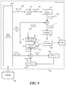
- FIG. 9 illustrates an example video decoder 900 that implements illumination compensation mode, consistent with some embodiments of the disclosure.
- the video decoder 900 is an image-decoding or video-decoding circuit that receives a bitstream 995 and decodes the content of the bitstream into pixel data of video frames for display.
- the video decoder 900 has several components or modules for decoding the bitstream 995 , including an inverse quantization module 905 , an inverse transform module 910 , an intra-prediction module 925 , a motion compensation module 930 , an in-loop filter 945 , a decoded picture buffer 950 , a MV buffer 965 , a MV prediction module 975 , and a parser 990 .
- the motion compensation module 930 is part of an inter-prediction module 940 .
- the modules 910 - 990 are modules of software instructions being executed by one or more processing units (e.g., a processor) of a computing device. In some embodiments, the modules 910 - 990 are modules of hardware circuits implemented by one or more ICs of an electronic apparatus. Though the modules 910 - 990 are illustrated as being separate modules, some of the modules can be combined into a single module.
- the parser 990 receives the bitstream 995 and performs initial parsing according to the syntax defined by a video-coding or image-coding standard.
- the parsed syntax element includes various header elements, flags, as well as quantized data (or quantized coefficients) 912 .
- the parser 990 parses out the various syntax elements by using entropy-coding techniques such as context-adaptive binary arithmetic coding (CABAC) or Huffman encoding.
- CABAC context-adaptive binary arithmetic coding
- Huffman encoding Huffman encoding
- the inverse quantization module 905 de-quantizes the quantized data (or quantized coefficients) 912 to obtain transform coefficients, and the inverse transform module 910 performs inverse transform on the transform coefficients 916 to produce reconstructed residual signal 919 .
- the reconstructed residual signal 919 is added with predicted pixel data 913 from the intra-prediction module 925 or the motion compensation module 930 to produce decoded pixel data 917 .
- the decoded pixels data are filtered by the in-loop filter 945 and stored in the decoded picture buffer 950 .
- the decoded picture buffer 950 is a storage external to the video decoder 900 .
- the decoded picture buffer 950 is a storage internal to the video decoder 900 .
- the intra-prediction module 925 receives intra-prediction data from bitstream 995 and according to which, produces the predicted pixel data 913 from the decoded pixel data 917 stored in the decoded picture buffer 950 .
- the decoded pixel data 917 is also stored in a line buffer (not illustrated) for intra-picture prediction and spatial MV prediction.
- the content of the decoded picture buffer 950 is used for display.
- a display device 955 either retrieves the content of the decoded picture buffer 950 for display directly or retrieves the content of the decoded picture buffer to a display buffer.
- the display device receives pixel values from the decoded picture buffer 950 through a pixel transport.
- the motion compensation module 930 produces predicted pixel data 913 from the decoded pixel data 917 stored in the decoded picture buffer 950 according to motion compensation MVs (MC MVs). These motion compensation MVs are decoded by adding the residual motion data received from the bitstream 995 with predicted MVs received from the MV prediction module 975 .
- MC MVs motion compensation MVs
- the MV prediction module 975 generates the predicted MVs based on reference MVs that were generated for decoding previous video frames, e.g., the motion compensation MVs that were used to perform motion compensation.
- the MV prediction module 975 retrieves the reference MVs of previous video frames from the MV buffer 965 .
- the video decoder 900 stores the motion compensation MVs generated for decoding the current video frame in the MV buffer 965 as reference MVs for producing predicted MVs.
- the in-loop filter 945 performs filtering or smoothing operations on the decoded pixel data 917 to reduce the artifacts of coding, particularly at boundaries of pixel blocks.
- the filtering operation performed includes sample adaptive offset (SAO).
- the filtering operations include adaptive loop filter (ALF).
- FIG. 10 illustrates portions of the video decoder 900 that implement illumination compensation mode, consistent with some embodiments of the disclosure.
- an illumination compensation module 1000 receives decoded pixel data 917 of the current block that is the sum of the predicted pixel data 913 and the reconstructed residual 919 .
- the decoded pixel data 917 are motion-compensated pixels that may not have illumination compensation performed.
- the illumination compensation module 1000 Based on the motion-compensated pixels 917 , the illumination compensation module 1000 generates modified pixel data 1010 to be further processed and stored in the decoded picture buffer 950 and a line buffer 1050 .
- the decoded picture buffer 950 stores previously reconstructed blocks of the current frame as well as reference frames.
- the line buffer 1050 stores the last decoded row of CTUs or CUs just above the current CTU row.
- the illumination compensation module 1000 applies a linear model (based on a set of illumination compensation parameters) to modify the decoded pixel data 917 of the current block.
- the linear model is applied to refine the predicted pixel data 913 .
- the illumination compensation module 1000 may generate the linear model based on pixel data stored in the decoded picture buffer 950 and/or the line buffer 1050 .
- the neighboring samples of the current block may be derived based on the content of the decoded picture buffer 950 and/or the line buffer 1050
- the neighboring samples of the reference block may be derived based on the content of the decoded picture buffer 950 .
- a motion vector associated with the current block may be provided by the inter prediction module 940 to locate the pixels of the reference block and of its neighboring samples from the decoded picture buffer 950 .
- the illumination compensation module 1000 may also retrieve the linear model from a history buffer 1020 , which stores linear models (or illumination compensation parameters) of the recently coded blocks.
- the illumination compensation module 1000 may receive configuration settings of operations applicable to the current block (e.g., GBi, BIO, DMVR, and other prediction tools), as well as the configuration settings of the current block itself (e.g., its size). In some embodiments, these configuration settings are provided by the parser or entropy decoder 990 .
- FIG. 11 conceptually illustrates a process 1100 for performing illumination compensation mode of the current block.
- one or more processing units e.g., a processor
- a computing device implementing a video coder performs the process 1100 by executing instructions stored in a computer readable medium.
- an electronic apparatus implementing the video coder performs the process 1100 .
- the video coder receives (at step 1110 ) a first block of pixels in a first video picture to be coded as a current block.
- the blocks of pixels are reconstructed from residuals produced by an inverse transform operation and prediction pixel produced by inter-prediction or intra-prediction.
- the blocks of pixels is to be encoded in a bitstream as the current block.
- the block of pixels are decoded from a bitstream as the current block.
- the current block is associated with a motion vector that references a second block of pixels in a second video picture as a reference block.
- the video coder performs (at step 1120 ) inter-prediction for the current block by using the motion vector to generate a set of motion-compensated pixels for the current block.
- the video coder determines (at step 1130 ) whether to enable or disable illumination compensation mode for the current block based on (i) a position of the current block in a larger block, (ii) a size of the current block, or (iii) an inter-prediction setting of the current block.
- the current block may be a sub-block of a larger block or a CU of a CTU.
- the illumination compensation mode may be disabled if the current block is not a top-most block or a left-most block of the larger block or CTU.
- the illumination compensation mode is turned off when GBi, BIO, SPTMVP or ATMVP, Affine mode, DMVR, Multi-hypothesis Intra-Merge mode, Multi-hypothesis Merge mode, or Multi-hypothesis Merge+AMVP mode is turned on for the current block.
- the video coder determines (at step 1140 ) whether the illumination compensation mode is enabled or disabled. If illumination compensation mode is enabled, the process proceeds to 1160 . If illumination compensation is disabled, the process proceeds to 1150 .
- the video coder encodes the set of motion-compensated pixels of the current block into a bitstream or outputs the set of motion-compensated pixels of the current block for display.
- the video coder modifies the set of motion-compensated pixels of the current block by applying a linear model that is computed based on neighboring samples of the reference block and of the current block.
- the neighboring samples are identified based on a position of the current block within a larger block.
- the linear model is based on a set of illumination compensation parameters comprising a scaling factor and an offset for a linear model.
- the larger block may include multiple sub-blocks and the current block is a first sub-block. Neighboring pixels of the first sub-block are used as neighboring samples to compute the linear model that is used to modify the current block and other sub-blocks of the larger block.
- neighboring pixels of the larger block are sub-sampled and used as the neighboring samples to compute the linear model that is used to modify the current block and other sub-blocks of the larger block.
- the current block may be a CU in a CTU that includes multiple CUs.
- the identified neighboring samples of the current block are derived based on neighboring pixels of the CTU.
- the current block is a prediction unit (PU) and the larger block is a coding unit (CU) that includes a plurality of PUs and has a size that is greater than a threshold.
- the identified neighboring samples of the current block are derived based on neighboring pixels of the CU.
- the identified neighboring samples of the current block are neighboring pixels of the larger block that are vertically or horizontally aligned with the current block.
- the neighboring samples may include neighboring pixels above the larger block and no other pixels when the current block is at a top edge of the larger block but not at a left edge of the larger block.
- the neighboring samples may include neighboring pixels left of the larger block and no other pixels when the current block is at a left edge of the larger block but not at a top edge of the larger block.
- the neighboring samples are computed by using reconstructed pixels of a neighboring block based on prediction pixels and residual pixels when the residual pixels are available and by using the prediction pixels of the neighboring block when the residual pixels are not available.
- the linear model is inherited from a neighboring block of the current block (that provide the selected merge candidate).
- the video coder encodes (at step 1170 ) the modified set of motion-compensated pixels of the current block into a bitstream or outputs the modified set of motion-compensated pixels of the current block for display.
- Computer readable storage medium also referred to as computer readable medium.
- these instructions are executed by one or more computational or processing unit(s) (e.g., one or more processors, cores of processors, or other processing units), they cause the processing unit(s) to perform the actions indicated in the instructions.
- computational or processing unit(s) e.g., one or more processors, cores of processors, or other processing units
- Examples of computer readable media include, but are not limited to, CD-ROMs, flash drives, random-access memory (RAM) chips, hard drives, erasable programmable read only memories (EPROMs), electrically erasable programmable read-only memories (EEPROMs), etc.
- the computer readable media does not include carrier waves and electronic signals passing wirelessly or over wired connections.
- the term “software” is meant to include firmware residing in read-only memory or applications stored in magnetic storage which can be read into memory for processing by a processor.
- multiple software inventions can be implemented as sub-parts of a larger program while remaining distinct software inventions.
- multiple software inventions can also be implemented as separate programs.
- any combination of separate programs that together implement a software invention described here is within the scope of the present disclosure.
- the software programs when installed to operate on one or more electronic systems, define one or more specific machine implementations that execute and perform the operations of the software programs.
- FIG. 12 conceptually illustrates an electronic system 1200 with which some embodiments of the present disclosure are implemented.
- the electronic system 1200 may be a computer (e.g., a desktop computer, personal computer, tablet computer, etc.), phone, PDA, or any other sort of electronic device.
- Such an electronic system includes various types of computer readable media and interfaces for various other types of computer readable media.
- Electronic system 1200 includes a bus 1205 , processing unit(s) 1210 , a graphics-processing unit (GPU) 1215 , a system memory 1220 , a network 1225 , a read-only memory 1230 , a permanent storage device 1235 , input devices 1240 , and output devices 1245 .
- GPU graphics-processing unit
- the bus 1205 collectively represents all system, peripheral, and chipset buses that communicatively connect the numerous internal devices of the electronic system 1200 .
- the bus 1205 communicatively connects the processing unit(s) 1210 with the GPU 1215 , the read-only memory 1230 , the system memory 1220 , and the permanent storage device 1235 .
- the processing unit(s) 1210 retrieves instructions to execute and data to process in order to execute the processes of the present disclosure.
- the processing unit(s) may be a single processor or a multi-core processor in different embodiments. Some instructions are passed to and executed by the GPU 1215 .
- the GPU 1215 can offload various computations or complement the image processing provided by the processing unit(s) 1210 .
- the read-only-memory (ROM) 1230 stores static data and instructions that are used by the processing unit(s) 1210 and other modules of the electronic system.
- the permanent storage device 1235 is a read-and-write memory device. This device is a non-volatile memory unit that stores instructions and data even when the electronic system 1200 is off. Some embodiments of the present disclosure use a mass-storage device (such as a magnetic or optical disk and its corresponding disk drive) as the permanent storage device 1235 .
- the system memory 1220 is a read-and-write memory device. However, unlike storage device 1235 , the system memory 1220 is a volatile read-and-write memory, such a random access memory.
- the system memory 1220 stores some of the instructions and data that the processor uses at runtime.
- processes in accordance with the present disclosure are stored in the system memory 1220 , the permanent storage device 1235 , and/or the read-only memory 1230 .
- the various memory units include instructions for processing multimedia clips in accordance with some embodiments. From these various memory units, the processing unit(s) 1210 retrieves instructions to execute and data to process in order to execute the processes of some embodiments.
- the bus 1205 also connects to the input and output devices 1240 and 1245 .
- the input devices 1240 enable the user to communicate information and select commands to the electronic system.
- the input devices 1240 include alphanumeric keyboards and pointing devices (also called “cursor control devices”), cameras (e.g., webcams), microphones or similar devices for receiving voice commands, etc.
- the output devices 1245 display images generated by the electronic system or otherwise output data.
- the output devices 1245 include printers and display devices, such as cathode ray tubes (CRT) or liquid crystal displays (LCD), as well as speakers or similar audio output devices. Some embodiments include devices such as a touchscreen that function as both input and output devices.
- CTR cathode ray tubes
- LCD liquid crystal displays
- bus 1205 also couples electronic system 1200 to a network 1225 through a network adapter (not shown).
- the computer can be a part of a network of computers (such as a local area network (“LAN”), a wide area network (“WAN”), or an Intranet, or a network of networks, such as the Internet. Any or all components of electronic system 1200 may be used in conjunction with the present disclosure.
- Some embodiments include electronic components, such as microprocessors, storage and memory that store computer program instructions in a machine-readable or computer-readable medium (alternatively referred to as computer-readable storage media, machine-readable media, or machine-readable storage media).
- computer-readable media include RAM, ROM, read-only compact discs (CD-ROM), recordable compact discs (CD-R), rewritable compact discs (CD-RW), read-only digital versatile discs (e.g., DVD-ROM, dual-layer DVD-ROM), a variety of recordable/rewritable DVDs (e.g., DVD-RAM, DVD-RW, DVD+RW, etc.), flash memory (e.g., SD cards, mini-SD cards, micro-SD cards, etc.), magnetic and/or solid state hard drives, read-only and recordable Blu-Ray® discs, ultra-density optical discs, any other optical or magnetic media, and floppy disks.
- CD-ROM compact discs
- CD-R recordable compact
- the computer-readable media may store a computer program that is executable by at least one processing unit and includes sets of instructions for performing various operations.
- Examples of computer programs or computer code include machine code, such as is produced by a compiler, and files including higher-level code that are executed by a computer, an electronic component, or a microprocessor using an interpreter.
- ASICs application specific integrated circuits
- FPGAs field programmable gate arrays
- integrated circuits execute instructions that are stored on the circuit itself.
- PLDs programmable logic devices
- ROM read only memory
- RAM random access memory
- the terms “computer”, “server”, “processor”, and “memory” all refer to electronic or other technological devices. These terms exclude people or groups of people.
- display or displaying means displaying on an electronic device.
- the terms “computer readable medium,” “computer readable media,” and “machine readable medium” are entirely restricted to tangible, physical objects that store information in a form that is readable by a computer. These terms exclude any wireless signals, wired download signals, and any other ephemeral signals.
- any two components so associated can also be viewed as being “operably connected”, or “operably coupled”, to each other to achieve the desired functionality, and any two components capable of being so associated can also be viewed as being “operably couplable”, to each other to achieve the desired functionality.
- operably couplable include but are not limited to physically mateable and/or physically interacting components and/or wirelessly interactable and/or wirelessly interacting components and/or logically interacting and/or logically interactable components.
Landscapes
- Engineering & Computer Science (AREA)
- Multimedia (AREA)
- Signal Processing (AREA)
- Compression Or Coding Systems Of Tv Signals (AREA)
Abstract
Description
-
- collocated location x=sub-PU_i_x+integer(vec_init_sub_i_x)+shift_x
- collocated location y=sub-PU_i_y+integer(vec_init_sub_i_y)+shift_y
Claims (20)
Priority Applications (1)
| Application Number | Priority Date | Filing Date | Title |
|---|---|---|---|
| US17/051,269 US11343541B2 (en) | 2018-04-30 | 2019-04-29 | Signaling for illumination compensation |
Applications Claiming Priority (4)
| Application Number | Priority Date | Filing Date | Title |
|---|---|---|---|
| US201862664387P | 2018-04-30 | 2018-04-30 | |
| US201862785713P | 2018-12-28 | 2018-12-28 | |
| PCT/CN2019/085043 WO2019210829A1 (en) | 2018-04-30 | 2019-04-29 | Signaling for illumination compensation |
| US17/051,269 US11343541B2 (en) | 2018-04-30 | 2019-04-29 | Signaling for illumination compensation |
Related Parent Applications (1)
| Application Number | Title | Priority Date | Filing Date |
|---|---|---|---|
| PCT/CN2019/085043 A-371-Of-International WO2019210829A1 (en) | 2018-04-30 | 2019-04-29 | Signaling for illumination compensation |
Related Child Applications (1)
| Application Number | Title | Priority Date | Filing Date |
|---|---|---|---|
| US17/723,923 Continuation US20220248064A1 (en) | 2018-04-30 | 2022-04-19 | Signaling for illumination compensation |
Publications (2)
| Publication Number | Publication Date |
|---|---|
| US20210051345A1 US20210051345A1 (en) | 2021-02-18 |
| US11343541B2 true US11343541B2 (en) | 2022-05-24 |
Family
ID=68387028
Family Applications (2)
| Application Number | Title | Priority Date | Filing Date |
|---|---|---|---|
| US17/051,269 Active US11343541B2 (en) | 2018-04-30 | 2019-04-29 | Signaling for illumination compensation |
| US17/723,923 Abandoned US20220248064A1 (en) | 2018-04-30 | 2022-04-19 | Signaling for illumination compensation |
Family Applications After (1)
| Application Number | Title | Priority Date | Filing Date |
|---|---|---|---|
| US17/723,923 Abandoned US20220248064A1 (en) | 2018-04-30 | 2022-04-19 | Signaling for illumination compensation |
Country Status (4)
| Country | Link |
|---|---|
| US (2) | US11343541B2 (en) |
| CN (2) | CN112042189B (en) |
| TW (1) | TWI711300B (en) |
| WO (1) | WO2019210829A1 (en) |
Cited By (1)
| Publication number | Priority date | Publication date | Assignee | Title |
|---|---|---|---|---|
| US20220007046A1 (en) * | 2019-03-14 | 2022-01-06 | Huawei Technologies Co., Ltd. | Inter Prediction Method and Related Apparatus |
Families Citing this family (27)
| Publication number | Priority date | Publication date | Assignee | Title |
|---|---|---|---|---|
| US11290730B2 (en) * | 2017-10-05 | 2022-03-29 | Interdigital Vc Holdings, Inc. | Method and apparatus for adaptive illumination compensation in video encoding and decoding |
| JP7666928B2 (en) * | 2018-05-28 | 2025-04-22 | インターデジタル ヴイシー ホールディングス, インコーポレイテッド | Data dependencies in encoding/decoding |
| US11997311B2 (en) * | 2018-09-17 | 2024-05-28 | Hfi Innovation Inc. | Methods and apparatuses of combining multiple predictors for block prediction in video coding systems |
| EP3854098A1 (en) * | 2018-09-19 | 2021-07-28 | InterDigital VC Holdings, Inc. | Method and device for picture encoding and decoding |
| WO2020084502A1 (en) | 2018-10-23 | 2020-04-30 | Beijing Bytedance Network Technology Co., Ltd. | Video processing using local illumination compensation |
| CN113287317B (en) | 2018-10-23 | 2023-04-28 | 北京字节跳动网络技术有限公司 | Juxtaposed local illumination compensation and modified inter-frame codec tool |
| US11388394B2 (en) * | 2019-01-04 | 2022-07-12 | Qualcomm Incorporated | Local illumination compensation (LIC) for virtual pipeline data units (VPDUS) |
| US11985314B2 (en) * | 2019-01-10 | 2024-05-14 | Hfi Innovation Inc. | Methods and apparatuses of processing video data of out-of-bounds nodes |
| WO2020147747A1 (en) * | 2019-01-15 | 2020-07-23 | Beijing Bytedance Network Technology Co., Ltd. | Weighted prediction in video coding |
| WO2020147804A1 (en) | 2019-01-17 | 2020-07-23 | Beijing Bytedance Network Technology Co., Ltd. | Use of virtual candidate prediction and weighted prediction in video processing |
| CN111526362B (en) * | 2019-02-01 | 2023-12-29 | 华为技术有限公司 | Interframe prediction method and device |
| US11997308B2 (en) * | 2019-03-08 | 2024-05-28 | Interdigital Madison Patent Holdings, Sas | Local illumination compensation for video encoding or decoding |
| CN113545092B (en) * | 2019-03-08 | 2025-02-18 | 交互数字Vc控股公司 | Local illumination compensation for video encoding or decoding |
| CN120956887A (en) * | 2019-06-21 | 2025-11-14 | 松下电器(美国)知识产权公司 | Systems and methods for video decoding |
| US12167001B2 (en) * | 2019-06-21 | 2024-12-10 | Interdigital Ce Patent Holdings, Sas | Local illumination compensation flag inheritance |
| US11259016B2 (en) | 2019-06-30 | 2022-02-22 | Tencent America LLC | Method and apparatus for video coding |
| US11778322B2 (en) * | 2020-08-17 | 2023-10-03 | Mediatek Inc. | Method and apparatus for performing electronic image stabilization with dynamic margin |
| US12113987B2 (en) * | 2020-12-22 | 2024-10-08 | Qualcomm Incorporated | Multi-pass decoder-side motion vector refinement |
| US11924409B2 (en) * | 2021-02-21 | 2024-03-05 | Alibaba (China) Co., Ltd. | Systems and methods for inter prediction compensation |
| KR20240090228A (en) * | 2021-09-29 | 2024-06-21 | 엘지전자 주식회사 | Video encoding/decoding method and device, and recording medium storing bitstream |
| US12166998B2 (en) * | 2022-01-12 | 2024-12-10 | Tencent America LLC | Adjustment based local illumination compensation |
| US20250184538A1 (en) * | 2022-03-08 | 2025-06-05 | Guangdong Oppo Mobile Telecommunications Corp., Ltd. | Model adjustment for local illumination compensation in video coding |
| EP4573751A1 (en) * | 2022-08-19 | 2025-06-25 | Beijing Dajia Internet Information Technology Co., Ltd. | Method and apparatus for adaptive motion compensated filtering |
| WO2024037641A1 (en) * | 2022-08-19 | 2024-02-22 | Mediatek Inc. | Out-of-boundary reference block handling |
| JP2024047921A (en) * | 2022-09-27 | 2024-04-08 | シャープ株式会社 | Image Decoding Device |
| WO2025011496A1 (en) * | 2023-07-07 | 2025-01-16 | Mediatek Inc. | Local illumination compensation model inheritance |
| WO2025023735A1 (en) * | 2023-07-26 | 2025-01-30 | 현대자동차주식회사 | Image encoding/decoding method and device, and recording medium for storing bitstream |
Citations (15)
| Publication number | Priority date | Publication date | Assignee | Title |
|---|---|---|---|---|
| CN101193302A (en) | 2006-12-01 | 2008-06-04 | 三星电子株式会社 | Illumination Compensation Method and Device and Video Codec Method and Device |
| US20080170629A1 (en) | 2007-01-11 | 2008-07-17 | Samsung Electronics Co., Ltd. | Method and apparatus for deblocking-filtering video data |
| US20090323798A1 (en) * | 2008-06-25 | 2009-12-31 | International Business Machines Corporation | Method and system for low-complexity slepian-wolf rate estimation in wyner-ziv video encoding |
| US20110110429A1 (en) * | 2009-11-06 | 2011-05-12 | Samsung Electronics Co., Ltd. | Fast Motion Estimation Methods Using Multiple Reference Frames |
| US20120027097A1 (en) * | 2010-04-14 | 2012-02-02 | Jian-Liang Lin | Method for performing localized multihypothesis prediction during video coding of a coding unit, and associated apparatus |
| US20150326881A1 (en) | 2012-12-26 | 2015-11-12 | Sharp Kabushiki Kaisha | Image decoding device |
| CN105393534A (en) | 2013-06-18 | 2016-03-09 | 夏普株式会社 | Illumination compensation device, LM prediction device, image decoding device, image encoding device |
| US20160335752A1 (en) * | 2015-05-13 | 2016-11-17 | Samsung Electronics Co., Ltd. | Image signal providing apparatus and image signal providing method |
| US20160366415A1 (en) * | 2015-06-09 | 2016-12-15 | Qualcomm Incorporated | Systems and methods of determining illumination compensation parameters for video coding |
| US20170150186A1 (en) * | 2015-11-25 | 2017-05-25 | Qualcomm Incorporated | Flexible transform tree structure in video coding |
| CN107810635A (en) | 2015-06-16 | 2018-03-16 | Lg 电子株式会社 | Method and apparatus based on illuminance compensation prediction block in image compiling system |
| US20180098079A1 (en) * | 2016-10-05 | 2018-04-05 | Qualcomm Incorporated | Systems and methods of adaptively determining template size for illumination compensation |
| US20180192072A1 (en) * | 2017-01-04 | 2018-07-05 | Qualcomm Incorporated | Motion vector reconstructions for bi-directional optical flow (bio) |
| US20180262773A1 (en) * | 2017-03-13 | 2018-09-13 | Qualcomm Incorporated | Inter prediction refinement based on bi-directional optical flow (bio) |
| US20200177911A1 (en) * | 2017-06-28 | 2020-06-04 | Sharp Kabushiki Kaisha | Video encoding device and video decoding device |
Family Cites Families (21)
| Publication number | Priority date | Publication date | Assignee | Title |
|---|---|---|---|---|
| US8467346B2 (en) * | 2009-06-19 | 2013-06-18 | Futurewei Technologies, Inc. | Method and apparatus for generating time-frequency patterns for reference signal in an OFDM wireless communication system |
| US20120102154A1 (en) * | 2010-10-26 | 2012-04-26 | Futurewei Technologies, Inc. | Cloud-Based Transcoding Platform Systems and Methods |
| JP2013005077A (en) * | 2011-06-14 | 2013-01-07 | Sony Corp | Image processing device and method |
| US20140192862A1 (en) * | 2013-01-07 | 2014-07-10 | Research In Motion Limited | Methods and systems for prediction filtering in video coding |
| GB201305812D0 (en) * | 2013-03-28 | 2013-05-15 | Univ Warwick | Gesture tracking and classification |
| US9860529B2 (en) * | 2013-07-16 | 2018-01-02 | Qualcomm Incorporated | Processing illumination compensation for video coding |
| US10368068B2 (en) * | 2013-10-01 | 2019-07-30 | Telefonaktiebolaget Lm Ericsson (Publ) | Encoder and method for video processing |
| CN106134192B (en) * | 2014-03-25 | 2020-08-11 | 株式会社索思未来 | Image decoding device, image decoding method, and integrated circuit |
| CN107925775A (en) * | 2015-09-02 | 2018-04-17 | 联发科技股份有限公司 | Motion compensation method and device for video coding and decoding based on bidirectional prediction optical flow technology |
| US10362314B2 (en) * | 2015-11-27 | 2019-07-23 | Mediatek Inc. | Apparatus and method for video coding by intra-prediction |
| KR101698314B1 (en) * | 2015-12-09 | 2017-01-20 | 경북대학교 산학협력단 | Aparatus and method for deviding of static scene based on statistics of images |
| CN114786009B (en) * | 2016-03-16 | 2025-07-08 | 寰发股份有限公司 | Video data processing method and device for limiting block size in video coding |
| US10623774B2 (en) * | 2016-03-22 | 2020-04-14 | Qualcomm Incorporated | Constrained block-level optimization and signaling for video coding tools |
| US10560718B2 (en) * | 2016-05-13 | 2020-02-11 | Qualcomm Incorporated | Merge candidates for motion vector prediction for video coding |
| CN116708784A (en) * | 2016-07-12 | 2023-09-05 | 韩国电子通信研究院 | Image encoding/decoding method and recording medium used for the method |
| US20190182505A1 (en) * | 2016-08-12 | 2019-06-13 | Mediatek Inc. | Methods and apparatuses of predictor-based partition in video processing system |
| WO2018062892A1 (en) * | 2016-09-28 | 2018-04-05 | 엘지전자(주) | Method and apparatus for performing optimal prediction on basis of weight index |
| CN109845255A (en) * | 2016-10-03 | 2019-06-04 | 夏普株式会社 | System and method for deblocking filter to be applied to reconstructed video data |
| JP7044778B2 (en) * | 2016-11-28 | 2022-03-30 | エレクトロニクス アンド テレコミュニケーションズ リサーチ インスチチュート | Image decoding methods, image coding methods, and non-temporary computer-readable recording media |
| US10701366B2 (en) * | 2017-02-21 | 2020-06-30 | Qualcomm Incorporated | Deriving motion vector information at a video decoder |
| US11109062B2 (en) * | 2017-03-16 | 2021-08-31 | Mediatek Inc. | Method and apparatus of motion refinement based on bi-directional optical flow for video coding |
-
2019
- 2019-04-29 WO PCT/CN2019/085043 patent/WO2019210829A1/en not_active Ceased
- 2019-04-29 US US17/051,269 patent/US11343541B2/en active Active
- 2019-04-29 CN CN201980028800.5A patent/CN112042189B/en active Active
- 2019-04-29 CN CN202310804567.3A patent/CN116684594A/en active Pending
- 2019-04-30 TW TW108115036A patent/TWI711300B/en active
-
2022
- 2022-04-19 US US17/723,923 patent/US20220248064A1/en not_active Abandoned
Patent Citations (22)
| Publication number | Priority date | Publication date | Assignee | Title |
|---|---|---|---|---|
| US8774282B2 (en) | 2006-12-01 | 2014-07-08 | Samsung Electronics Co., Ltd. | Illumination compensation method and apparatus and video encoding and decoding method and apparatus using the illumination compensation method |
| CN101193302A (en) | 2006-12-01 | 2008-06-04 | 三星电子株式会社 | Illumination Compensation Method and Device and Video Codec Method and Device |
| US20080170629A1 (en) | 2007-01-11 | 2008-07-17 | Samsung Electronics Co., Ltd. | Method and apparatus for deblocking-filtering video data |
| US20090323798A1 (en) * | 2008-06-25 | 2009-12-31 | International Business Machines Corporation | Method and system for low-complexity slepian-wolf rate estimation in wyner-ziv video encoding |
| US20110110429A1 (en) * | 2009-11-06 | 2011-05-12 | Samsung Electronics Co., Ltd. | Fast Motion Estimation Methods Using Multiple Reference Frames |
| US20120027097A1 (en) * | 2010-04-14 | 2012-02-02 | Jian-Liang Lin | Method for performing localized multihypothesis prediction during video coding of a coding unit, and associated apparatus |
| US8891608B2 (en) * | 2010-04-14 | 2014-11-18 | Mediatek Inc. | Method for performing localized multihypothesis prediction during video coding of a coding unit, and associated apparatus |
| US20150326881A1 (en) | 2012-12-26 | 2015-11-12 | Sharp Kabushiki Kaisha | Image decoding device |
| US10200688B2 (en) | 2013-06-18 | 2019-02-05 | Sharp Kabushiki Kaisha | Illumination compensation device and illumination compensation method |
| CN105393534A (en) | 2013-06-18 | 2016-03-09 | 夏普株式会社 | Illumination compensation device, LM prediction device, image decoding device, image encoding device |
| US20160335752A1 (en) * | 2015-05-13 | 2016-11-17 | Samsung Electronics Co., Ltd. | Image signal providing apparatus and image signal providing method |
| US20160366415A1 (en) * | 2015-06-09 | 2016-12-15 | Qualcomm Incorporated | Systems and methods of determining illumination compensation parameters for video coding |
| CN107710764A (en) | 2015-06-09 | 2018-02-16 | 高通股份有限公司 | Systems and methods for determining illumination compensation status for video coding |
| CN107810635A (en) | 2015-06-16 | 2018-03-16 | Lg 电子株式会社 | Method and apparatus based on illuminance compensation prediction block in image compiling system |
| US20180176592A1 (en) * | 2015-06-16 | 2018-06-21 | Lg Electronics Inc. | Method and device for predicting block on basis of illumination compensation in image coding system |
| US10477231B2 (en) | 2015-06-16 | 2019-11-12 | Lg Electronics Inc. | Method and device for predicting block on basis of illumination compensation in image coding system |
| US20170150186A1 (en) * | 2015-11-25 | 2017-05-25 | Qualcomm Incorporated | Flexible transform tree structure in video coding |
| US20180098079A1 (en) * | 2016-10-05 | 2018-04-05 | Qualcomm Incorporated | Systems and methods of adaptively determining template size for illumination compensation |
| US10880570B2 (en) * | 2016-10-05 | 2020-12-29 | Qualcomm Incorporated | Systems and methods of adaptively determining template size for illumination compensation |
| US20180192072A1 (en) * | 2017-01-04 | 2018-07-05 | Qualcomm Incorporated | Motion vector reconstructions for bi-directional optical flow (bio) |
| US20180262773A1 (en) * | 2017-03-13 | 2018-09-13 | Qualcomm Incorporated | Inter prediction refinement based on bi-directional optical flow (bio) |
| US20200177911A1 (en) * | 2017-06-28 | 2020-06-04 | Sharp Kabushiki Kaisha | Video encoding device and video decoding device |
Non-Patent Citations (3)
| Title |
|---|
| B. Choi, J. Han, C. Kim and S. Ko, "Motion-Compensated Frame Interpolation Using Bilateral Motion Estimation and Adaptive Overlapped Block Motion Compensation," in IEEE Transactions on Circuits and Systems for Video Technology, vol. 17, No. 4, pp. 407-416, Apr. 2007, doi: 10.1109/TCSVT.2007.893835. * |
| Chinese language office action dated Jul. 9, 2020, issued in application No. TW 108115036. |
| International Search Report and Written Opinion dated Jun. 27, 2019, issued in application No. PCT/CN2019/085043. |
Cited By (3)
| Publication number | Priority date | Publication date | Assignee | Title |
|---|---|---|---|---|
| US20220007046A1 (en) * | 2019-03-14 | 2022-01-06 | Huawei Technologies Co., Ltd. | Inter Prediction Method and Related Apparatus |
| US12069288B2 (en) * | 2019-03-14 | 2024-08-20 | Huawei Technologies Co., Ltd. | Inter prediction method and related apparatus |
| US20250016353A1 (en) * | 2019-03-14 | 2025-01-09 | Huawei Technologies Co., Ltd. | Inter prediction method and related apparatus |
Also Published As
| Publication number | Publication date |
|---|---|
| CN116684594A (en) | 2023-09-01 |
| CN112042189B (en) | 2023-07-21 |
| US20220248064A1 (en) | 2022-08-04 |
| WO2019210829A1 (en) | 2019-11-07 |
| TW201946470A (en) | 2019-12-01 |
| TWI711300B (en) | 2020-11-21 |
| CN112042189A (en) | 2020-12-04 |
| US20210051345A1 (en) | 2021-02-18 |
Similar Documents
| Publication | Publication Date | Title |
|---|---|---|
| US20220248064A1 (en) | Signaling for illumination compensation | |
| US11553173B2 (en) | Merge candidates with multiple hypothesis | |
| US11297348B2 (en) | Implicit transform settings for coding a block of pixels | |
| US11166037B2 (en) | Mutual excluding settings for multiple tools | |
| US11172203B2 (en) | Intra merge prediction | |
| US11115653B2 (en) | Intra block copy merge list simplification | |
| US11546603B2 (en) | Triangle prediction with applied-block settings and motion storage settings | |
| US20240357082A1 (en) | Using template matching for refining candidate selection | |
| US20200120339A1 (en) | Intra Prediction For Multi-Hypothesis | |
| WO2018127188A1 (en) | Multi-hypotheses merge mode | |
| WO2020103946A1 (en) | Signaling for multi-reference line prediction and multi-hypothesis prediction | |
| WO2020233702A1 (en) | Signaling of motion vector difference derivation | |
| WO2019161798A1 (en) | Intelligent mode assignment in video coding | |
| WO2025153044A1 (en) | Intra coding information based on cascaded vector for video coding | |
| WO2025011483A1 (en) | Local illumination compensation with merge slope adjustment | |
| WO2024022144A1 (en) | Intra prediction based on multiple reference lines | |
| US20250330568A1 (en) | Updating motion attributes of merge candidates | |
| WO2024017004A1 (en) | Reference list reordering in video coding |
Legal Events
| Date | Code | Title | Description |
|---|---|---|---|
| FEPP | Fee payment procedure |
Free format text: ENTITY STATUS SET TO UNDISCOUNTED (ORIGINAL EVENT CODE: BIG.); ENTITY STATUS OF PATENT OWNER: LARGE ENTITY |
|
| STPP | Information on status: patent application and granting procedure in general |
Free format text: APPLICATION DISPATCHED FROM PREEXAM, NOT YET DOCKETED |
|
| AS | Assignment |
Owner name: MEDIATEK INC., TAIWAN Free format text: ASSIGNMENT OF ASSIGNORS INTEREST;ASSIGNORS:TSAI, CHIA-MING;CHEN, CHUN-CHIA;HSU, CHIH-WEI;AND OTHERS;REEL/FRAME:054811/0985 Effective date: 20201228 |
|
| STPP | Information on status: patent application and granting procedure in general |
Free format text: DOCKETED NEW CASE - READY FOR EXAMINATION |
|
| STPP | Information on status: patent application and granting procedure in general |
Free format text: NON FINAL ACTION MAILED |
|
| STPP | Information on status: patent application and granting procedure in general |
Free format text: RESPONSE TO NON-FINAL OFFICE ACTION ENTERED AND FORWARDED TO EXAMINER |
|
| STPP | Information on status: patent application and granting procedure in general |
Free format text: NOTICE OF ALLOWANCE MAILED -- APPLICATION RECEIVED IN OFFICE OF PUBLICATIONS |
|
| AS | Assignment |
Owner name: HFI INNOVATION INC., TAIWAN Free format text: ASSIGNMENT OF ASSIGNORS INTEREST;ASSIGNOR:MEDIATEK INC.;REEL/FRAME:059339/0015 Effective date: 20211201 Owner name: HFI INNOVATION INC., TAIWAN Free format text: ASSIGNMENT OF ASSIGNOR'S INTEREST;ASSIGNOR:MEDIATEK INC.;REEL/FRAME:059339/0015 Effective date: 20211201 |
|
| STPP | Information on status: patent application and granting procedure in general |
Free format text: PUBLICATIONS -- ISSUE FEE PAYMENT VERIFIED |
|
| STCF | Information on status: patent grant |
Free format text: PATENTED CASE |
|
| MAFP | Maintenance fee payment |
Free format text: PAYMENT OF MAINTENANCE FEE, 4TH YEAR, LARGE ENTITY (ORIGINAL EVENT CODE: M1551); ENTITY STATUS OF PATENT OWNER: LARGE ENTITY Year of fee payment: 4 |