US11336912B2 - Image decoding device, image encoding device, and image decoding method - Google Patents
Image decoding device, image encoding device, and image decoding method Download PDFInfo
- Publication number
- US11336912B2 US11336912B2 US17/112,593 US202017112593A US11336912B2 US 11336912 B2 US11336912 B2 US 11336912B2 US 202017112593 A US202017112593 A US 202017112593A US 11336912 B2 US11336912 B2 US 11336912B2
- Authority
- US
- United States
- Prior art keywords
- side information
- section
- value
- difference value
- encoding
- Prior art date
- Legal status (The legal status is an assumption and is not a legal conclusion. Google has not performed a legal analysis and makes no representation as to the accuracy of the status listed.)
- Active
Links
Images


Classifications
-
- H—ELECTRICITY
- H04—ELECTRIC COMMUNICATION TECHNIQUE
- H04N—PICTORIAL COMMUNICATION, e.g. TELEVISION
- H04N19/00—Methods or arrangements for coding, decoding, compressing or decompressing digital video signals
- H04N19/44—Decoders specially adapted therefor, e.g. video decoders which are asymmetric with respect to the encoder
-
- H—ELECTRICITY
- H04—ELECTRIC COMMUNICATION TECHNIQUE
- H04N—PICTORIAL COMMUNICATION, e.g. TELEVISION
- H04N19/00—Methods or arrangements for coding, decoding, compressing or decompressing digital video signals
- H04N19/10—Methods or arrangements for coding, decoding, compressing or decompressing digital video signals using adaptive coding
- H04N19/169—Methods or arrangements for coding, decoding, compressing or decompressing digital video signals using adaptive coding characterised by the coding unit, i.e. the structural portion or semantic portion of the video signal being the object or the subject of the adaptive coding
- H04N19/17—Methods or arrangements for coding, decoding, compressing or decompressing digital video signals using adaptive coding characterised by the coding unit, i.e. the structural portion or semantic portion of the video signal being the object or the subject of the adaptive coding the unit being an image region, e.g. an object
- H04N19/176—Methods or arrangements for coding, decoding, compressing or decompressing digital video signals using adaptive coding characterised by the coding unit, i.e. the structural portion or semantic portion of the video signal being the object or the subject of the adaptive coding the unit being an image region, e.g. an object the region being a block, e.g. a macroblock
-
- H—ELECTRICITY
- H04—ELECTRIC COMMUNICATION TECHNIQUE
- H04N—PICTORIAL COMMUNICATION, e.g. TELEVISION
- H04N19/00—Methods or arrangements for coding, decoding, compressing or decompressing digital video signals
- H04N19/10—Methods or arrangements for coding, decoding, compressing or decompressing digital video signals using adaptive coding
- H04N19/102—Methods or arrangements for coding, decoding, compressing or decompressing digital video signals using adaptive coding characterised by the element, parameter or selection affected or controlled by the adaptive coding
- H04N19/124—Quantisation
-
- H—ELECTRICITY
- H04—ELECTRIC COMMUNICATION TECHNIQUE
- H04N—PICTORIAL COMMUNICATION, e.g. TELEVISION
- H04N19/00—Methods or arrangements for coding, decoding, compressing or decompressing digital video signals
- H04N19/10—Methods or arrangements for coding, decoding, compressing or decompressing digital video signals using adaptive coding
- H04N19/134—Methods or arrangements for coding, decoding, compressing or decompressing digital video signals using adaptive coding characterised by the element, parameter or criterion affecting or controlling the adaptive coding
- H04N19/167—Position within a video image, e.g. region of interest [ROI]
-
- H—ELECTRICITY
- H04—ELECTRIC COMMUNICATION TECHNIQUE
- H04N—PICTORIAL COMMUNICATION, e.g. TELEVISION
- H04N19/00—Methods or arrangements for coding, decoding, compressing or decompressing digital video signals
- H04N19/10—Methods or arrangements for coding, decoding, compressing or decompressing digital video signals using adaptive coding
- H04N19/189—Methods or arrangements for coding, decoding, compressing or decompressing digital video signals using adaptive coding characterised by the adaptation method, adaptation tool or adaptation type used for the adaptive coding
- H04N19/196—Methods or arrangements for coding, decoding, compressing or decompressing digital video signals using adaptive coding characterised by the adaptation method, adaptation tool or adaptation type used for the adaptive coding being specially adapted for the computation of encoding parameters, e.g. by averaging previously computed encoding parameters
- H04N19/198—Methods or arrangements for coding, decoding, compressing or decompressing digital video signals using adaptive coding characterised by the adaptation method, adaptation tool or adaptation type used for the adaptive coding being specially adapted for the computation of encoding parameters, e.g. by averaging previously computed encoding parameters including smoothing of a sequence of encoding parameters, e.g. by averaging, by choice of the maximum, minimum or median value
-
- H—ELECTRICITY
- H04—ELECTRIC COMMUNICATION TECHNIQUE
- H04N—PICTORIAL COMMUNICATION, e.g. TELEVISION
- H04N19/00—Methods or arrangements for coding, decoding, compressing or decompressing digital video signals
- H04N19/46—Embedding additional information in the video signal during the compression process
- H04N19/463—Embedding additional information in the video signal during the compression process by compressing encoding parameters before transmission
-
- H—ELECTRICITY
- H04—ELECTRIC COMMUNICATION TECHNIQUE
- H04N—PICTORIAL COMMUNICATION, e.g. TELEVISION
- H04N19/00—Methods or arrangements for coding, decoding, compressing or decompressing digital video signals
- H04N19/65—Methods or arrangements for coding, decoding, compressing or decompressing digital video signals using error resilience
-
- H—ELECTRICITY
- H04—ELECTRIC COMMUNICATION TECHNIQUE
- H04N—PICTORIAL COMMUNICATION, e.g. TELEVISION
- H04N19/00—Methods or arrangements for coding, decoding, compressing or decompressing digital video signals
- H04N19/70—Methods or arrangements for coding, decoding, compressing or decompressing digital video signals characterised by syntax aspects related to video coding, e.g. related to compression standards
-
- H—ELECTRICITY
- H04—ELECTRIC COMMUNICATION TECHNIQUE
- H04N—PICTORIAL COMMUNICATION, e.g. TELEVISION
- H04N19/00—Methods or arrangements for coding, decoding, compressing or decompressing digital video signals
- H04N19/90—Methods or arrangements for coding, decoding, compressing or decompressing digital video signals using coding techniques not provided for in groups H04N19/10-H04N19/85, e.g. fractals
- H04N19/91—Entropy coding, e.g. variable length coding [VLC] or arithmetic coding
Definitions
- the present invention relates to an encoding device for generating encoded data by encoding an image. Further, the present invention relates to a decoding device for decoding the encoded data generated by use of such an encoding device.
- Video encoding devices have been used for efficiently transmitting or recording videos.
- Examples of a specific video encoding method encompass H.264/MPEG-4 AVC (hereinafter abbreviated as H264/AVC) (described in Non Patent Literature 1) and a method employed in KTA software which is a joint development codec in VCEG (Video Coding Expert Group).
- an image (picture) constituting a video is managed in a hierarchical structure which is constituted by (i) a plurality of slices into which the image is divided, (ii) a plurality of macroblocks into which each of the plurality of slices is divided, (iii) a plurality of sub blocks into which each of the plurality of macroblocks is divided, and (iv) a plurality of blocks into which each of the plurality of macroblocks or the plurality of sub blocks is divided.
- a video encoding device based on H264/AVC (1) subjects an image to DCT transform, (2) quantizes a frequency component obtained by the DCT transform (Discrete Cosine Transform), and (3) variable-length-codes the quantized frequency component, thereby obtaining an encoded image.
- Quantization step employed in quantization is variable with respect to each macroblock, and the video encoding device is designed to encode a quantization parameter that designates the size of the quantization step and to supply the encoded quantization parameter as well as the encoded image to a video decoding device.
- the process for encoding the quantization parameter is detailed below with reference to (a) of FIG. 7 , FIG. 11 , and FIG. 12 .
- FIG. 7 is a view schematically showing a slice constituted by macroblocks MB 1 to MBn.
- FIG. 12 is a view showing examples of difference values of quantization parameters assigned to the macroblocks MB 1 to MBn.
- FIG. 11 is a table showing relations among difference values of quantization parameters, code numbers, and binary sequences outputted when binarizing the code numbers.
- the video encoding device determines, with respect to each picture, a default value pic_init_qp of a quantization parameter of the picture (hereinafter “picture default QP value”). Furthermore, the video encoding device determines, with respect to each slice included in the picture, a default value (SliceQP Y ) of a quantization parameter of the slice (hereinafter “slice default QP value”). Furthermore, the video encoding device determines, with respect to each slice, a difference value slice_qp_delta obtained by subtracting, from the slice default QP value of the slice, the picture default QP value of the picture including the slice.
- QP difference value a difference value obtained by subtracting, from the determined quantization parameter, a quantization parameter of a macroblock MBi-1 previous by one to the macroblock MBi in raster scan order.
- a QP difference value mb_qp_delta of a first macroblock MB 1 in raster scan order is obtained by subtracting, from a quantization parameter determined with respect to the macroblock MB 1 , a slice default QP value SliceQP Y of a slice including the macroblock MB 1 .
- the video encoding device binarizes, based on the table shown in FIG. 11 , the QP difference value mb_qp_delta generated as above. That is, the QP difference value is transformed, when the absolute value thereof is n, into a binary sequence whose length is 2n or 2n+1 by unary binarization.
- the amount of codes of an encoded image (main information) can be reduced efficiently without impairing subjective image quality of a decoded image decoded by a video decoding device, and 2) by regulating a quantization parameter suitably, the amount of codes of an encoded image with respect to each frame can be kept at a desired rate.
- the amount of codes of a QP difference value supplied as side information together with the main information to the video decoding device is not sufficiently reduced.
- the amount of codes of a QP difference value occupies approximately 10% of the whole encoded data supplied to a video decoding device. This is because the amount of codes of a QP difference value is in relation to the absolute value of the QP difference value as is seen from FIG. 11 .
- a main object of the present invention is to realize an encoding device capable of reducing the amount of codes of a quantization parameter supplied to a decoding device compared with a conventional art, and a decoding device capable of inverse-quantization based on a quantization parameter supplied from such an encoding device.
- an encoding device of the present invention is an encoding device for quantizing, in accordance with a value of a quantization parameter, an image in each of a plurality of unit regions constituting an input image to be encoded, the encoding device comprising: setting means for setting a quantization parameter used in encoding each unit region, the setting means setting an quantization parameter for each unit region in such a manner that a difference between a quantization parameter for a unit region and a predetermined reference value is equal to one of n predetermined difference values; transform means for transforming, with respect to each unit region, the difference between the quantization parameter for the unit region and the predetermined reference value into an integer in accordance with a transform rule by which the n difference values are transformed into n number of integers, respectively; and binary sequence generation means for generating a binary sequence having a length corresponding to a size of an absolute value of the integer into which the difference is transformed by the transform means, a total of absolute values of the n integers being
- a conventional encoding device is designed to generate a binary sequence having a length corresponding to the size of an absolute value of a difference between quantization parameters with respect to each unit region.
- a difference between quantization parameters in each unit region is transformed into an integer, and a binary sequence having a length corresponding to the size of the absolute value of the integer is generated. Furthermore, since the total of the absolute values of the n integers is smaller than the total of the absolute values of the n difference values serving as candidates for the difference between the quantization parameters, the absolute value of the integer obtained by the transform is statistically smaller than the absolute value of the difference value to be transformed.
- the binary sequence generated from the difference between the quantization parameters has a smaller length in the encoding device of the present invention than in the conventional encoding device. This yields an effect of further reducing an amount of codes of quantization parameters supplied to a decoding device, compared with the conventional art.
- a decoding device of the present invention is a decoding device for decoding encoded data to set quantization parameters regarding unit regions constituting a decoded image, the decoding device comprising: extraction means for extracting data of binary sequences regarding the unit regions from the encoded data;
- integer generation means for generating integers corresponding to lengths of the binary sequences regarding the unit regions from the data of binary sequences extracted by the extraction means; and specifying means for specifying, according to information in which n integers are related to n difference values regarding quantization parameters, respectively, difference values for the unit regions based on integers for the unit regions that are generated by the integer generation means, the quantization parameters for the unit regions being generated based on the difference values specified by the specifying means.
- the decoding device of the present invention when receiving encoded data including the binary sequence from the encoding device of the present invention, can appropriately specify difference values regarding individual unit regions based on the encoded data. That is, the decoding device of the present invention can suitably specify quantization parameters regarding individual unit regions supplied from the encoding device of the present invention.
- the decoding device of the present invention can carry out inverse-quantization based on quantization parameters supplied from the encoding device of the present invention.
- an encoding device of the present invention is an encoding device for quantizing, in accordance with a value of a quantization parameter, an image in each of a plurality of unit regions constituting an input image to be encoded, the encoding device comprising: selection means for selecting, in a predetermined order, a plurality of third unit regions constituting each of the plurality of unit regions; determination means for determining a difference value of a quantization parameter for one of third unit regions to be quantized in each of the plurality of unit regions, said one of third unit regions being firstly selected by the selection means; and calculation means for calculating the value of the quantization parameter to be referred to when quantizing images in the third unit regions to be quantized in each of the plurality of unit regions, the value of the quantization parameter being calculated based on the difference value of the quantization parameter for the unit region which is determined by the determination means.
- “quantizing an image” may be one of quantizing a residual image between an input image and a predicted
- the encoding device of the present invention determines a difference value of a quantization parameter for one third unit region selected from each unit region, and using the difference value of the quantization parameter, determines a quantization parameter of the third unit region to be quantized.
- an encoding device without the above features determines a quantization parameter for each third unit region to be quantized, and using the quantization parameter for each third unit region, determines a difference value of the quantization parameter for the third unit region.
- the encoding device of the present invention is only required to determine one difference value of a quantization parameter per unit region and transmit the difference value to the decoding device, whereas an encoding device without the above features is required to transmit difference values of quantization parameters for individual third unit regions included in one unit region to the decoding device.
- the encoding device of the present invention can further reduce an amount of codes of a quantization parameter, compared with the conventional art.
- a decoding device of the present invention is a decoding device for decoding encoded data to set quantization parameters regarding unit regions constituting a decoded image, the decoding device comprising: selection means for selecting, in a predetermined order, a plurality of third unit regions constituting each of the unit regions constituting the decoded image; reading means for reading, from the encoded data, a difference value of a quantization parameter for one of third unit regions to be inverse-quantized in each of the unit regions constituting the decoded image, said one of third unit regions being firstly selected by the selection means; and specifying means for specifying a value of the quantization parameter to be referred to when a quantization image in each third unit region to be inverse-quantized in each of the unit regions constituting the decoded image, the specifying being made based on the difference value of the quantization parameter read out in said each of the unit regions by the reading means.
- the quantization image is, for example, an image on a frequency domain constituted by quantized DCT coefficients decoded from encoded data.
- the quantization image By subjecting the quantization image to inverse-quantization and inverse-frequency transformation, it is possible to obtain a decoded image on a spatial domain.
- the decoding device of the present invention reads out a difference value of a quantization parameter in one third unit region selected from each unit region, and using the difference value, determines quantization parameters for individual third unit regions to be inverse-quantized in the unit region.
- a decoding device without the above features reads out difference values of quantization parameters from individual third unit regions to be inverse-quantized in each unit region, and using the read out difference values, determines quantization parameters for individual third unit regions to be inverse-quantized in the unit region.
- the decoding device of the present invention can specify, with a smaller load, quantization parameters to be used in inverse-quantization.
- the encoding device of the present invention can reduce an amount of codes in a quantization parameter to be supplied to a decoding device, compared with the conventional art. Furthermore, the decoding device can carry out inverse-quantization based on the quantization parameter supplied from such an encoding device.
- FIG. 1 is a block diagram showing a configuration of a video encoding device in accordance with an embodiment.
- FIG. 2 is a flowchart showing operations of a side information generation section and a side information encoding section that are included in the video encoding device in accordance with the embodiment.
- FIG. 3 is a flowchart showing another operations of the side information generation section and the side information encoding section that are included in the video encoding device in accordance with the embodiment.
- FIG. 4 is a block diagram showing a configuration of a video decoding device in accordance with the embodiment.
- FIG. 5 is a block diagram showing operations of a side information decoding section and an MB setting section that are included in the video decoding device in accordance with the embodiment.
- FIG. 6 is a block diagram showing another operations of the side information decoding section and the MB setting section that are included in the video decoding device in accordance with the embodiment.
- FIG. 7 (a) and (b) of FIG. 7 schematically show configurations of slices, respectively.
- FIG. 8 (a) to (e) of FIG. 8 show specific examples of a QP difference value table.
- FIG. 9 (a) of FIG. 9 shows relations among values of indices, code numbers serving as inputs for unary binarization, and binary sequences serving as outputs from unary binarization. (b) of FIG. 9 shows relations among values of indices and binary sequences serving as outputs from fixed-length binarization.
- FIG. 10 (a) and (b) of FIG. 10 show examples of amount of codes in encoding a QP difference value table.
- FIG. 11 is a view of a conventional art, showing relations among QP difference values, code numbers serving as inputs for unary binarization, and binary sequences serving as outputs from unary binarization.
- FIG. 12 is a view showing an example of a picture default QP value set with respect to each picture, a slice default QP value set with respect to each slice, and a QP value and a QP difference value that are set with respect to each macroblock.
- FIG. 13 is a view hierarchically showing individual information included in side information.
- FIG. 14 is a block diagram showing a configuration of a video decoding device in accordance with another embodiment.
- FIG. 15 is a block diagram showing a configuration of a video encoding device in accordance with another embodiment.
- FIG. 16 is a view showing an example of a picture parameter set.
- FIG. 17 is a view schematically showing positions of CUs whose QP difference values are encoded in QP encoding unit regions.
- FIG. 18 is a view showing an example of coding_unit syntax. (a) of FIG. 18 shows a former part of syntax. (b) of FIG. 18 shows a latter part of the syntax.
- FIG. 19 is a view showing another example of coding_unit syntax. (a) of FIG. 19 shows a former part of syntax. (b) of FIG. 19 shows a latter part of the syntax.
- FIG. 20 is a view showing another example of coding_unit syntax.
- (a) of FIG. 20 shows a former part of syntax.
- (b) of FIG. 20 shows a latter part of the syntax.
- FIG. 21 is a view showing an example of transform_tree syntax.
- FIG. 22 is a block diagram showing a configuration of a video encoding device in accordance with another embodiment.
- FIG. 23 is a view showing another example of transform_tree syntax.
- FIG. 24 is a view showing another example of transform_tree syntax.
- FIG. 25 is a block diagram showing a configuration of a video decoding device in accordance with another embodiment.
- FIG. 26 is a block diagram showing a configuration of a video encoding device in accordance with another embodiment.
- FIG. 27 is a view showing another example of coding_unit syntax. (a) of FIG. 27 shows a former part of syntax. (b) of FIG. 27 shows a latter part of the syntax.
- FIG. 28 is a view showing another example of coding_unit syntax. (a) of FIG. 28 shows a former part of syntax. (b) of FIG. 28 shows a latter part of the syntax.
- FIG. 29 is a block diagram showing a configuration of a video decoding device in accordance with another embodiment.
- FIG. 30 is a block diagram showing a configuration of a video encoding device in accordance with another embodiment.
- FIG. 31 is a view showing another example of coding_unit syntax. (a) of FIG. 31 shows a former part of syntax. (b) of FIG. 31 shows a latter part of the syntax.
- FIG. 32 is a block diagram showing a configuration of a video decoding device in accordance with another embodiment.
- FIG. 33 is a block diagram showing a configuration of a video encoding device in accordance with another embodiment.
- FIG. 34 is a view showing another example of coding_unit syntax. (a) of FIG. 34 shows a former part of syntax. (b) of FIG. 34 shows a latter part of the syntax.
- FIG. 35 is a block diagram showing a configuration of a video decoding device in accordance with another embodiment.
- FIG. 36 is a block diagram showing a configuration of a video encoding device in accordance with another embodiment.
- FIG. 1 is a block diagram showing a configuration of the video encoding device 2 .
- the video encoding device 2 includes a side information determination section 21 , a side information encoding section 22 , an MB setting section 23 , an MB encoding section 24 , a variable-length code multiplexing section 25 , an MB decoding section 26 , and a frame memory 27 .
- the video encoding device 2 encodes an input image # 100 to generate encoded data # 1 and outputs the encoded data # 1 .
- the video encoding device 2 is a video encoding device partially using the technique employed in H264/AVC standard.
- a process of encoding the input image # 100 includes DCT, quantization etc.
- the video encoding device 2 carries out a quantization process by changing a quantization level with respect to each macroblock (quantization unit region).
- the side information determination section 21 determines side information based on the input image # 100 , and outputs the determined side information as side information # 21 .
- the side information # 21 is supplied to the side information encoding section 22 as well as inputted to the MB setting section 23 .
- the side information # 21 includes a picture parameter set which is a set of parameters regarding the input image # 100 , a slice header which is header information with respect to each slice included in the input image # 100 , a macroblock layer which is a set of parameters with respect to each block included in a slice, and the like.
- Each of the picture parameter set and the slice header includes a picture default QP value and a difference value between a slice default QP value and the picture default QP value.
- the side information determination section determines, with respect to each slice, a set of QP difference values for limiting QP values assignable to macroblocks included in the slice. That is, QP values assignable to the macroblock MBi included in the slice are limited so that QP difference values between the QP values assignable to the macroblock MBi and the QP value assigned to the macroblock MBi-1 included in the same slice are included in the set of the QP difference values.
- the side information determination section 21 generates, with respect to each slice (table generation unit region), a QP difference value table regarding the slice, and incorporates the generated QP difference value table into a corresponding slice header.
- the QP difference value table regarding the slice is a table generated by relating indices indicative of individual QP difference values included in the set of the QP difference values (the indices are different integers for individual QP difference values) to those individual QP difference values.
- the QP difference value table may be one for encoding rules for generating a QP difference value table, as described later in the section (Additional matter 3).
- the present invention may be arranged such that a video encoding device and a video decoding device each include a plurality of predetermined QP difference value tables, and indices for switching the QP difference value tables are encoded.
- the side information determination section 21 incorporates, into a macroblock layer, an index indicative of a QP difference value between a QP value assigned to a macroblock MBi and a QP value assigned to a macroblock MBi-1. How the side information determination section 21 determines the set of the QP difference values and how the side information determination section 21 generates the QP difference value table are described later.
- the side information encoding section 22 encodes the side information # 21 , and outputs encoded side information # 22 .
- the encoded side information # 22 is supplied to the variable-length code multiplexing section 25 .
- the MB setting section 23 divides the input image # 100 into a plurality of slices based on the side information # 21 , and divides each slice into a plurality of macroblocks, and outputs macroblock images # 23 regarding individual macroblocks.
- the MB setting section 23 calculates values of quantization parameters (QP values) regarding the individual macroblock images # 23 based on the side information # 21 (this calculation will be detailed later). Then, the individual macroblock images # 23 are sequentially supplied together with the calculated QP values to the MB encoding section 24 .
- QP values quantization parameters
- the MB encoding section 24 generates MB encoded data # 24 with respect to each of the sequentially inputted macroblock images # 23 , and supplies the MB encoded data # 24 to the variable-length code multiplexing section 25 .
- the MB encoding section 24 generates the MB encoded data # 24 specifically as follows.
- the MB encoding section 24 subjects individual blocks constituting the macroblock image # 23 to DCT, and quantizes DCT coefficients of individual blocks at quantization levels based on the QP values supplied together with the macroblock image # 23 . Then, the MB encoding section 24 subjects the data obtained by quantization to a variable-length encoding process so as to generate the MB encoded data # 24 .
- variable-length code multiplexing section 25 multiplexes the encoded side information # 22 with the MB encoded data # 24 to generate encoded data # 1 and outputs the generated encoded data # 1 .
- the MB decoding section 26 sequentially decodes the MB encoded data # 24 corresponding to the inputted individual macroblocks so as to generate decoded images # 26 corresponding to the individual macroblocks, and outputs the generated decoded images # 26 .
- the decoded images # 26 are supplied to the frame memory 27 .
- the inputted decoded images # 26 are stored in the frame memory 27 .
- decoded images corresponding to all macroblocks prior in raster scan order to the certain macroblock are stored in the frame memory 27 .
- the method by which the side information determination section 21 determines the set of QP difference values for limiting QP values assignable to macroblocks may be any method. Specific examples thereof are as follows.
- a QP difference value table to be included in a slice header of a P slice is one shown in (b) of FIG. 8 for example.
- the QP difference value table to be incorporated into the slice header of the P slice is one shown in (c) of FIG. 8 for example.
- the side information determination section 21 generates a QP difference value table in which individual QP difference values are related to indices whose absolute values are smaller than absolute values of the QP difference values (table shown in (a) to (c) of FIG. 8 ).
- the QP difference value table generated by the side information determination section 21 should have at least the characteristics below.
- the QP difference value table may be any table as long as the amount of codes of all quantization data outputted when individual indices are transformed into code numbers and subjected to a quantization process based on unary binarization is smaller than the amount of codes of all quantization data outputted when individual QP difference values are transformed into code numbers and are subjected to a quantization process based on unary binarization.
- the QP difference value table may be a table in which QP difference values and indices are related to each other one by one, and the total of absolute values of individual indices is smaller than the total of absolute values of individual QP difference values.
- FIG. 2 is a flow chart showing the flow of the above operations.
- the side information determination section 21 generates a QP difference value table corresponding to the slice type of a slice included in the input image # 100 , and incorporates the QP difference value table into a corresponding slice header in the side information # 21 (step S 41 ).
- the side information determination section 21 temporarily sets the QP value of the macroblock MBi to be within the range defined by the H264/AVC standard. Then, the side information determination section 21 judges whether the value (temporal QP difference value) obtained by subtracting the already determined QP value of the macroblock MBi-1 from the temporarily set QP value of the macroblock MBi is included as a QP difference value in the QP difference value table.
- the side information determination section 21 determines the temporarily set QP value as the QP value of the macroblock MBi.
- the side information determination section 21 subtracts the slice default QP value from the QP value of the headmost macroblock MB 1 to obtain the QP difference value for the headmost macroblock MB 1 . Then, the side information determination section 21 refers to the QP difference value table generated in the immediately preceding step S 41 and transforms the QP difference value to an index (step S 43 ). The side information determination section 21 incorporates the obtained index into a corresponding macroblock layer in the side information # 21 .
- the QP difference value is transformed into the index by using the QP difference value table.
- transform is possible without using the QP difference value table.
- a rule for setting transform of a QP difference value to an index by calculation or transform of an index to a QP difference value by calculation is referred to as a transform rule.
- the side information determination section 21 calculates the QP difference value for the macroblock MBi by subtracting the QP value of the macroblock MBi-1 from the QP value of the macroblock MBi. Then, the side information determination section 21 transforms the QP difference value into an index by referring to the QP difference value table generated in the immediately preceding step S 41 (step S 44 ). The side information determination section 21 incorporates the obtained index into a corresponding macroblock layer in the side information # 21 .
- the side information determination section 21 determines whether the macroblock treated in the step S 44 is the last macroblock MBn in the slice (step S 45 ). When the side information determination section 21 determines that the macroblock treated in the step S 44 is not the last macroblock MBn in the slice, the process goes back to the step S 44 . On the other hand, when the side information determination section 21 determines that the macroblock treated in the step S 44 is the last macroblock MBn in the slice, the process goes to the step S 46 .
- the side information determination section 21 judges whether a slice which has not been subjected to treatments in the steps S 41 to S 44 exists in the input image # 100 or not (step S 46 ). When the side information determination section 21 judges that such a slice exists, the side information determination section 21 subjects the slice which has not been subjected to the treatments in the steps S 41 to S 44 to the treatments in the steps S 41 to S 44 . On the other hand, when the side information determination section 21 judges that such a slice does not exist, the side information determination section 21 supplies, to the side information encoding section 22 and the MB setting section 23 , the side information # 21 whose macroblock layer includes indices and whose slice header includes a QP difference value table. Then, the process goes to the step S 47 .
- the side information encoding section 22 to which the side information # 21 has been inputted transforms the indices into code numbers and carries out a binarization process on the input code numbers based on unary binarization. That is, an index whose absolute value is n is transformed into a binary sequence with a length of 2n or 2n+1 (i.e. binary sequence with a length corresponding to the size of the absolute value of the index) based on the table shown in (a) of FIG. 9 (step S 47 ).
- the side information encoding section 22 transforms binary sequences having been stored in individual macroblock layers in the process of the step S 47 into algebraic signs, and encodes the QP difference value tables included in individual slice headers in the side information # 21 (step S 48 ).
- the side information encoding section 22 carries out an encoding process on the whole of the side information # 21 (including the process of S 48 ) and then supplies the encoded side information # 22 to the variable-length code multiplexing section 25 .
- the MB setting section 23 divides the input image # 100 into a plurality of slices, and divides each slice into a plurality of macroblocks. Then, the MB setting section 23 sequentially supplies the macroblock images # 23 regarding individual macroblocks together with QP values regarding the macroblock images # 23 to the MB encoding section 24 .
- the MB setting section 23 calculates, based on the input side information # 21 , the QP value to be supplied to the MB encoding section 24 as follows.
- the MB setting section 23 refers to: an index included in a macroblock layer corresponding to the macroblock image # 23 ; and a QP difference value table included in a slice header corresponding to a slice partially constituted by the macroblock image # 23 .
- the MB setting section 23 refers to a QP difference value related to the referred index in the QP difference value table. Furthermore, the MB setting section 23 regards, as a QP value to be supplied to the MB encoding section 24 , a value obtained by adding the QP difference value to the QP value for the macroblock image # 23 which value was supplied to the MB encoding section 24 immediately before.
- the MB encoding section 24 for quantizing and encoding the macroblock image # 23 based on an input QP value and members ranging from the variable-length code multiplexing section 25 to the frame memory 27 operate in accordance with the H264/AVC standard, and accordingly details thereof are omitted here.
- the side information encoding section 22 encodes the size of the QP difference value table (i.e. the number of indices (QP difference values) in the table) and individual QP difference values.
- the side information encoding section 22 encodes the size 9 of the QP difference value table and individual QP difference values ( ⁇ 8, ⁇ 6, . . . , 0, . . . , 6, 8).
- the side information encoding section 22 may encode a QP difference value corresponding to the index 0 as it is and as for other index, encode a difference obtained by subtracting, from said other index, a QP difference value of index smaller by 1 than said other index.
- QP difference values or differences of the QP difference values may be encoded by unary binarization.
- an amount of codes when the QP difference value table shown in (b) of FIG. 8 is encoded based on unary binarization is described below for two cases: a case where individual QP difference values are encoded as they are, and a case where a QP difference value corresponding to the index 0 is encoded as it is and as for other index, a difference of a QP difference value corresponding to other index is encoded.
- mb_qp_delta[i] in (a) and (b) of FIG. 10 indicates a QP difference value of an index i.
- dd[i,i ⁇ 1] mb_qp_delta[i] ⁇ mb_qp_delta[i ⁇ 1].
- FIG. 3 is a flow chart showing the operations of the side information determination section 21 and the side information encoding section 22 of the present Modification Example.
- (b) of FIG. 7 is a view showing a slice constituted by a plurality of enlarged macroblocks (second unit region) each constituted by a plurality of macroblocks.
- each enlarged macroblock is configured such that all macroblocks therein have similar pixel characteristics.
- the video encoding device 2 determines the QP difference value with respect to each of a plurality of macroblocks included in an enlarged macroblock.
- a macroblock for which the QP difference value is determined is selected in raster scan order in each enlarged macroblock.
- QP difference values for four macroblocks in an enlarged macroblock LMB 1 are determined in the order of MB 1 , MB 2 , MB 3 , and MB 4 .
- the video encoding device 2 carries out the above process with respect to each of the plurality of enlarged macroblocks in the slice.
- the enlarged macroblock to be subjected to the above process is selected in raster scan order in the slice.
- a plurality of enlarged macroblocks in a slice in (b) of FIG. 7 are subjected to the above process in the order of enlarged macroblocks LMB 1 , LMB 2 , LMB 3 , . . . .
- the video encoding device 2 assigns a QP value to a headmost macroblock (specific unit region) in an enlarged macroblock by a method based on the H264/AVC standard (hereinafter, the QP value of the headmost macroblock is also referred to as QP head ).
- the video encoding device 2 transforms the QP difference value directly into a code number without transforming the QP value into an index, and transforms the code number into a binary sequence by unary binarization.
- the video encoding device 2 transforms the QP difference value for the QP value assigned to the headmost macroblock in that enlarged macroblock into an index based on the QP difference value table shown in (e) of FIG. 8 . Then, the video encoding device 2 transforms the index into a code number and transforms the code number into a binary sequence by unary binarization.
- the number of QP values assignable to macroblocks other than the headmost macroblock (three QP values of QP head ⁇ 2, QP head , QP head +2) is smaller than the number of QP values assignable to individual macroblocks in the above Embodiment (thirteen in the case of using the table shown in (a) of FIG. 8 and nine in the case of using the tables shown in (b) to (d) of FIG. 8 .
- the maximum value of the absolute value of the QP difference value that can be determined for a macroblock other than the headmost macroblock is 2 which is a predetermined number close to 0.
- the side information determination section 21 generates a QP difference value table as shown in (e) of FIG. 8 , and incorporates the QP difference value table into a corresponding slice header in the side information # 21 (step S 61 ).
- a target enlarged macroblock e.g. LMB 1
- the processes of S 62 to S 68 below in the order of selection e.g. the order of MB 1 , MB 2 , MB 3 , and MB 4
- the target macroblocks are selected in raster scan order (the order of LMB 1 , LMB 2 . . . ) from a plurality of enlarged macroblocks constituting the whole of a slice.
- the side information determination section 21 judges whether the selected macroblock MBi is a headmost macroblock MB 1 in a slice.
- the side information determination section 21 judges that the selected macroblock MBi is the headmost macroblock MB 1 (YES in step S 62 ), the side information determination section 21 determines the QP value of the macroblock MB 1 by a method based on the H264/AVC standard. Then, the side information determination section 21 causes the QP difference value obtained by subtracting a slice default QP value from the determined QP value to be stored in a corresponding macroblock layer (step S 67 ), and the process goes to the step S 68 .
- step S 62 when the side information determination section 21 judges that the selected macroblock MBi is not the headmost macroblock MB 1 (NO in step S 62 ), the side information determination section 21 judges whether the selected macroblock MBi is a headmost macroblock in one of other enlarged macroblocks (MB 5 , MB 9 etc.) (step S 63 ).
- the side information determination section 21 judges that the selected macroblock MBi is a headmost macroblock in an enlarged macroblock (YES in step S 63 ).
- the side information determination section 21 determines the QP value of the macroblock MBi by a method based on the H264/AVC standard. Then, the side information determination section 21 causes the QP difference value obtained by subtracting the QP value determined for the macroblock MBi-1 from the determined QP value for the macroblock MBi to be stored in a corresponding macroblock layer (step S 66 ), and the process goes to the step S 68 .
- the side information determination section 21 determines the QP difference value of the macroblock (step S 64 ).
- the side information determination section 21 temporarily sets the QP value of the macroblock based on the H264/AVC standard. Then, the side information determination section 21 subtracts, from the temporarily set QP value, a QP value of a headmost macroblock included in the same enlarged macroblock as the macroblock is included in to obtain a temporal QP difference value, and judges whether the temporal QP difference value is included as a QP difference value in the QP difference value table.
- the side information determination section 21 determines the temporarily set QP value as the QP value of the macroblock MBi.
- the side information determination section 21 determines, as the QP difference value of the macroblock MBi, a QP difference value closest to the temporal QP difference value out of the plurality of QP difference values included in the QP difference value table.
- the number of candidates of QP difference values to be determined for macroblocks other than the headmost macroblock in the enlarged macroblock in the step S 64 is smaller than the number of candidates of QP difference values to be determined for the headmost macroblock in the enlarged macroblock.
- a value obtained by adding the determined QP difference value to the QP value of the macroblock MBi-1 is determined as the QP value of the macroblock MBi.
- the side information determination section 21 refers to the QP difference value table generated in the immediately preceding step S 61 , and transforms the QP difference value determined in the step S 64 into an index.
- the side information determination section 21 incorporates the obtained index into a corresponding macroblock layer in the side information # 21 (step S 65 ), and the process goes to the step S 68 .
- the side information determination section 21 judges whether the macroblock having been processed is the last macroblock in the slice.
- the process goes to the step S 62 .
- the process goes to the step S 69 .
- the side information determination section 21 judges whether a slice having not been subjected to the processes in the steps S 61 to S 68 exists in the input image # 100 or not (step S 69 ). When judging that such a slice exists, the side information determination section 21 subjects the slice to the process in the steps S 61 to S 68 . On the other hand, when judging that such a slice does not exist, the side information determination section 21 supplies the side information # 21 to the side information encoding section 22 and the MB setting section 23 and the process goes to the step S 70 .
- the side information encoding section 22 receives the side information # 21 , and transforms indices or QP difference values included in individual macroblock layers in the side information # 21 into code numbers, and subjects the code numbers to a binarization process based on unary binarization (step S 70 ).
- the side information encoding section 22 encodes QP difference value tables included in individual slice headers in the side information # 21 (step S 71 ).
- the side information encoding section 22 carries out an encoding process (including the process in S 70 ) on the whole of the side information # 21 and then supplies the encoded side information # 22 to the variable-length code multiplexing section 25 .
- the MB setting section 23 calculates a QP value to be supplied together with the macroblock image # 23 to the MB encoding section 24 .
- the MB setting section 23 refers to an index included in the macroblock layer corresponding to the macroblock image # 23 and a QP difference value table included in a slice header corresponding to a slice partially constituted by the macroblock image # 23 . Then, the MB setting section 23 refers to the QP difference value related to the index which the MB setting section has referred to in the QP difference value table. Furthermore, the MB setting section 23 adds the QP difference value to the QP value regarding the macroblock image # 23 supplied to the MB encoding section 24 just before, thereby obtaining a QP value to be supplied to the MB encoding section 24 .
- the MB setting section 23 refers to a QP difference value included in a macroblock layer corresponding to the macroblock image # 23 .
- the MB setting section 23 adds the QP difference value to the QP value regarding the macroblock image # 23 supplied to the MB encoding section 24 just before, thereby obtaining a QP value to be supplied to the MB encoding section 24 .
- the side information determination section 21 generates a QP difference value table in which individual QP difference values are related to indices whose absolute values are smaller than absolute values of the QP difference values as shown in (a) to (c) of FIG. 8 .
- the side information determination section 21 may generate a table of (d) of FIG. 8 which is not designed as above.
- the table of (d) of FIG. 8 is generated as below.
- the side information determination section 21 determines, with respect to each of the macroblocks MB 1 to MBn in the slice, the QP difference value for the macroblock out of the set of the QP difference values determined for the slice so as to determine the QP value of the macroblock.
- the side information determination section 21 generates a table in which the most frequent value (0 in (d) of FIG. 8 ), the second frequent value (4 in (d) of FIG. 8 ), the third frequent value ( ⁇ 6 in (d) of FIG. 8 ) . . . which are set based on the n determined QP difference values are related to indices 0, 1, ⁇ 1, . . . . That is, in the table, a more frequent QP difference value is related to an index with a smaller absolute value. Furthermore, individual frequencies, i.e. ratios of individual QP difference values included in a group consisting of n QP difference values are calculated by the side information determination section 21 .
- the total sum of the absolute values of the QP difference values included in the QP difference value table may be equal to the total sum of the absolute values of the indices.
- the quantization unit region is a macroblock.
- the present invention is not limited to this. That is, although an explanation was made above as to a case where determination of a QP value, transform of a QP difference value into an index, binarization of an index, and quantization of an image by using the QP value are made with respect to each macroblock, such operations may be made not with respect to each macroblock but with respect to a unit larger than the macroblock or a unit smaller than the macroblock (i.e. with respect to each partition, each block of 8 pixels ⁇ 8 lines, each block of 4 pixels ⁇ 4 lines etc.).
- the table generation unit region is a slice.
- the present invention is not limited to this. That is, although an explanation was made as to a case where the QP difference value table is generated with respect to each slice, the QP difference value table may be generated with respect to a unit larger than the slice (with respect to each picture etc.) or a unit smaller than the slice (with respect to each macroblock etc.).
- the table generation unit region must include a plurality of quantization unit regions.
- the present invention may be arranged such that the QP difference value table is not generated with respect to each table generation unit region. That is, a predetermined QP difference value table is stored in a storage section (not shown), and the QP difference value table stored in the storage section is used instead of a QP difference value table generated with respect to each table generation unit region. In this case, it is unnecessary for the video encoding device 2 to encode the QP difference value table and output the encoded QP difference value table to the outside. This is because when the video decoding device 1 has the same QP difference value table, the video decoding device 1 can derive the QP difference value from the index after decoding side information encoded data # 11 a.
- the slice type is determined with respect to each slice, the value of factor is determined according to the slice type, and the QP difference value table according to the value of factor is generated.
- the QP difference value table may be generated as follows.
- the QP difference value table when the QP difference value table is encoded, individual QP difference values are encoded.
- the QP difference value table may be encoded as follows. That is, as shown by the QP difference value table of (b) of FIG. 8 and the QP difference value table of (c) of FIG. 8 , when the QP difference value table determined by the value of factor and the size of the QP difference value table is encoded, the value of factor may be encoded instead of encoding individual QP difference values. In this case, the amount of codes of the QP difference value table is further reduced.
- the Examples 1 to 3 there are a plurality of methods for calculating the QP difference value table from the same factor.
- the present invention may be arranged to select and use one of the methods shown by the Examples 1 to 3. In this case, information necessary for determining the method for calculating the QP difference value table may be explicitly encoded. That is, both of method and factor may be encoded.
- Information to be outputted as encoded data to the outside may be any information as long as the information relates individual QP difference values to indices one by one.
- the information may be encoded QP difference values or may be encoded values of factor.
- the information may include not only individual QP difference values or the values of factor but also the values of indices.
- the video encoding device and the video decoding device may be arranged to each include a plurality of predetermined transform rules or a plurality of QP difference value tables and encodes a transform rule index (roughness-specifying flag) for switching the plurality of transform rules (or the plurality of QP difference value tables).
- a transform rule index roughness-specifying flag
- unary binarization is used in order to transform an index into a binary sequence.
- the present invention is not limited to this.
- unary binarization or fixed-length binarization as shown in (b) of FIG. 9 may be used depending on the situation.
- a binary sequence obtained by these binarizations may be subjected to another encoding.
- Context-based Adaptive Binary Arithmetic Coding (CABAC) defined in H. 264/AVC may be applied.
- the side information encoding section 22 is substantially constant (whether the difference between the maximum value and the minimum value of the ratio is not more than a predetermined threshold), and when the ratio is substantially constant, the side information encoding section 22 may use fixed-length binarization and when otherwise, the side information encoding section 22 may use unary binarization.
- the length of a binary sequence obtained by fixed-length binarization depends on logarithm of the number of possible QP difference values with a radix of 2. For example, when the number of possible QP difference values is 7, the length of a binary sequence is 3. Therefore, in a case where the possible QP difference values are limited by using a QP difference value table, the length of the binary sequence is reduced compared with a case of not limiting QP difference values and so the amount of codes is reduced, too.
- a QP difference value of a quantization unit region of interest is obtained from a difference between a QP value of the quantization unit region of interest and a predetermined reference value.
- the predetermined reference value is a QP value of a quantization unit region just before the quantization unit region of interest in the order of processing.
- the present invention is not limited to this. That is, the predetermined reference value may be a QP value of a quantization unit region adjacent to the quantization unit region the QP difference value of which is to be obtained (e.g. quantization unit region adjacent to the quantization unit region of interest to the left or to the above).
- the predetermined reference value may be a QP value of a quantization unit region close to the quantization unit region the QP difference value of which is to be obtained (i.e. quantization unit region positioned in a predetermined range from the quantization unit region of interest), or may be a value that changes with respect to each process unit larger than a quantization unit (e.g. slice default QP value).
- the predetermined reference value may be a specific constant (e.g. 0).
- the video encoding device 2 sets the QP value of each macroblock in such a manner that the QP difference value of a pair of macroblocks with consecutive orders of encoding is one of n QP difference values.
- the video encoding device 2 sets the QP value of the macroblock MB 3 in such a manner that the QP difference value of the macroblock MB 3 with respect to the macroblock MB 2 is 1 which is one of nine QP difference values registered in the QP difference value table shown in (d) of FIG. 8 : ⁇ 9, ⁇ 2, . . . , 3, and 8. Then, the video encoding device 2 transforms the QP difference value 1 of the macroblock MB 3 with respect to the macroblock MB 2 into an index 2 corresponding to the QP difference value 1 out of 9 indices.
- the side information encoding section 22 generates a binary sequence having a length corresponding to the size of the absolute value of the index. For example, the side information encoding section 22 generates a binary sequence “1110” having a length of 4 from the index of 2, and generates a binary sequence “111110” having a length of 6 from the index 3.
- the total of absolute values of n indices is smaller than the total of absolute values of n difference values.
- the total of absolute values of 9 indices is 20
- the video encoding device 2 can reduce the amount of codes of quantization parameters compared with a conventional art.
- the following explains a configuration of the video decoding device (decoding device) 1 in accordance with the Embodiment with reference to FIGS. 4-10 and 12 .
- the video decoding device 1 is a video decoding device a part of which uses the technique employed in the H264/AVC standard.
- the video decoding device 1 is a device which decodes encoded data # 1 from the video encoding device 2 so as to generate and output a decoded image # 2 .
- FIG. 4 is a block diagram showing a configuration of the video decoding device 1 .
- the video decoding device 1 includes a variable-length code inverse-multiplexing section 11 , a side information decoding section 12 , a MB setting section 13 , a MB decoding section 14 , and a frame memory 15 .
- the encoded data # 1 inputted to the video decoding device 1 is inputted to the variable-length code inverse-multiplexing section 11 .
- the variable-length code inverse-multiplexing section 11 reverse-multiplexes the input encoded data # 1 so as to divide the encoded data # 1 into side information encoded data # 11 a which is encoded data regarding side information and encoded data # 11 b which is encoded data regarding a picture, and outputs the side information encoded data # 11 a and the encoded data # 11 b to the side information decoding section 12 and the MB setting section 13 , respectively.
- the side information decoding section 12 decodes side information # 12 from the side information encoded data # 11 a , and outputs the side information # 12 to the MB setting section 13 .
- the side information # 12 includes a picture parameter set which is the set of parameters regarding the input image # 100 , a slice header which is header information with respect to each slice included in the input image # 100 , a macroblock layer which is the set of parameters with respect to each macroblock included in the slice, and the like.
- the MB setting section 13 divides, based on the input side information # 12 , the encoded data # 11 b into a plurality of slices and divides each slice into individual encoded data # 13 corresponding to individual macroblocks, and sequentially outputs the individual encoded data # 13 to the MB decoding section 14 .
- the MB setting section 13 calculates, based on the side information # 12 , a QP value for reverse-quantizing the encoded data # 13 , and outputs the obtained QP value together with the encoded data # 13 to the MB decoding section 14 .
- the MB decoding section 14 sequentially decodes and reverse-quantizes the encoded data # 13 corresponding to individual inputted macroblocks (reverse-quantized unit region) so as to generate and output decoded images # 2 corresponding to individual macroblocks. Furthermore, the decoded images # 2 are outputted to the frame memory 15 , too.
- the decoded images # 2 are stored in the frame memory 15 .
- decoded images corresponding to all macroblocks preceding the certain macroblock in the order of processing are stored in the frame memory 15 .
- FIG. 5 is a flowchart showing the flow of the operations of the side information decoding section 12 and the MB setting section 13 .
- the side information decoding section 12 decodes a QP difference value table included in each slice header from the side information encoded data # 11 a (step S 1 ). Thereafter, the side information decoding section 12 takes out, from the side information encoded data # 11 a , an index included in each macroblock layer (step S 2 ). Specifically, the side information decoding section 12 generates a binary sequence by arithmetic-decoding data having been arithmetic-encoded in the step S 48 by the side information encoding section 22 of the video encoding device 2 , and subjects the binary sequence to a reverse process of unary binarization (conversion of binary sequence into multivalued sequence) so as to take out an index. Then, the side information decoding section 12 supplies side information # 12 including the QP difference value table and the index to the MB setting section 13 .
- the MB setting section 13 calculates QP values to be sequentially outputted together with the encoded data # 13 to the MB decoding section 14 (step S 3 ).
- the MB setting section 13 refers to the QP difference value table included in a slice header of the side information # 12 and to the index included in a macroblock layer (macroblock layer corresponding to macroblock indicated by the encoded data # 13 ) of the side information # 12 .
- the slice header of the side information # 12 is a slice header corresponding to a slice partially constituted by a macroblock indicated by the encoded data # 13 .
- the MB setting section 13 refers to a QP difference value related to the index in the QP difference value table, and calculates a QP value from the QP difference value.
- the MB decoding section 14 for decoding the input encoded data # 13 and reverse-quantizing the decoded data based on a QP value inputted together with the encoded data # 13 , and the frame memory 15 operate in accordance with the H264/AVC standard, and therefore details thereof are omitted here.
- FIG. 6 is a flowchart showing the operations of the side information decoding section 12 and the MB setting section 13 .
- the side decoding section 12 and the MB setting section operate in accordance with the present Modification Example when the side information determination section 21 and the side information encoding section 22 of the video encoding device 2 operate in accordance with the present Modification Example.
- the side information decoding section 12 decodes a QP difference value table included in each slice header from the side information encoded data # 11 a (step S 21 ).
- All macroblock layers included in the side information encoded data # 11 a are subjected to the processes of S 22 and subsequent steps mentioned below.
- the macroblock layers subjected to the processes of S 22 and subsequent steps are selected in the same order as the order for selecting macroblocks to be processed by the side information determination section 21 of the video encoding device 2 .
- the macroblock layer corresponding to the macroblock MBi is subjected to S 22 and subsequent steps at the i-th order.
- the side information decoding section 12 judges whether the selected macroblock layer is a macroblock layer of the headmost macroblock (specific unit region) in an enlarged macroblock (second unit region) (step S 22 ).
- the side information decoding section 12 judges that the selected macroblock layer is not a macroblock layer of the headmost macroblock (NO in step S 22 )
- the side information decoding section 12 takes out an index included in the macroblock layer from the side information encoded data # 11 a (step S 23 ).
- the side information decoding section 12 subjects the binary sequence generated in the step S 70 by the side information encoding section 22 of the video encoding device 2 to a reverse process of unary binarization (conversion of binary sequence into multivalued sequence) so as to take out an index. Then, the side information decoding section 12 supplies the side information # 12 including the QP difference value table and the index to the MB setting section 13 .
- the MB setting section 13 calculates a QP value to be outputted together with the encoded data # 13 to the MB decoding section 14 (step S 24 ).
- the MB setting section 13 refers to the QP difference value table included in the slice header of the side information # 12 and the index included in the macroblock layer. Then, the MB setting section 13 refers to a QP difference value related to the index in the QP difference value table, and calculates a QP value from the QP difference value by a method based on the H264/AVC standard.
- the side information decoding section 12 judges that the selected macroblock layer is a macroblock layer of the headmost macroblock (YES in step S 22 )
- the side information decoding section 12 takes out a QP difference value included in the macroblock layer from the side information encoded data # 11 a
- the MB setting section 13 calculates a QP value (step S 25 ).
- the side information decoding section 12 takes out a QP difference value corresponding to a multivalued integer obtained by subjecting the binary sequence generated in the step S 70 by the side information encoding section 22 of the video encoding device 2 to a reverse process of unary binarization (conversion of binary sequence into multivalued sequence).
- the side information decoding section 12 supplies the side information # 12 including the QP difference value to the MB setting section 13 , and the MB setting section 13 calculates a QP value from the QP difference value included in the side information # 12 by a method based on the H264/AVC standard.
- step S 26 When all the macroblock layers have been subjected to the processes of the steps S 23 and S 24 (or the process of the step S 25 ) (YES in step S 26 ), the process is finished. When there is a macroblock layer having not been subjected to the process (NO in step S 26 ), the process goes to the step S 22 .
- the inverse-quantization unit region is a macroblock.
- the reverse phase quantization unit region may be a unit region larger than a macroblock or smaller than a macroblock as long as the size of an inverse-quantization unit region is the same as the size of a quantization unit region in the video encoding device 2 .
- the QP value for inverse-quantization of an image of each inverse-quantization unit region is calculated from the QP difference value.
- the QP difference value table in the slice header is referred to in order to obtain the QP difference value from the index. That is, the QP difference value tables to be referred to in order to obtain the QP difference value from the index are switched with respect to each slice.
- the decoding device of the present invention is not limited to this.
- the QP difference value tables to be referred to may be switched with respect to each unit region of the same size as the table generation unit region of the video encoding device 2 .
- a specific process for decoding the QP difference value table may be as follows.
- each QP difference value may be decoded by a reverse process of unary binarization.
- the encoded data of the QP difference value table includes the value of factor and the size of the QP difference value table, these are decoded.
- the QP difference value table may be generated based on the decoded value of factor and the decoded size of the QP difference value table. That is, in a case where the size of the QP difference value table is 2n+1 and the value of factor is f, there may be generated a QP difference value table in which indices are set to be ⁇ n, ⁇ n+1, . . . , 0, . . .
- n ⁇ 1, and n are set to ⁇ 1*f*n, ⁇ 1*f*(n ⁇ 1), . . . , 0, f*(n ⁇ 1), and f*n.
- the video decoding device 1 carries out a process for setting quantization parameters regarding individual macroblocks constituting a decoded image.
- the side information decoding section 12 extracts binary sequence data regarding individual macroblocks from the encoded data # 1 . Then, the side information decoding section 12 generates indices corresponding to the length of binary sequences from the binary sequence data.
- the MB setting section 13 refers to the QP difference value table in which mutually different n indices are related to n QP difference values one by one, thereby specifying the QP difference values of individual macroblocks from the indices which the side information decoding section 12 has generated with respect to each of the macroblocks. Thereafter, the MB setting section 13 calculates QP values of individual macroblocks from the QP difference values by a method based on the H264/AVC standard.
- the video decoding device 1 subjects individual macroblocks to the inverse-quantization process using the calculated QP values, thereby generating a decoded image constituted by the macroblocks.
- encoded data which is generated by a video encoding device in accordance with each of Second Embodiment and subsequent embodiments and which is referred to by a video decoding device in accordance with each of Second Embodiment and subsequent embodiments.
- a sign “ 4 ” of a video encoding device, a sign “ 3 ” of a video decoding device, and a sign “# 4 ” of encoded data indicate the video encoding device in accordance with Second Embodiment, the video decoding device in accordance with Second Embodiment, and encoded data referred to in Second Embodiment, respectively.
- Encoded data referred to by video encoding devices and video decoding devices in accordance with Third Embodiment and subsequent embodiments can be understood by replacing the signs used in the following explanation with signs used in those embodiments.
- the encoded data # 4 includes, for example, a sequence and a plurality of pictures constituting the sequence.
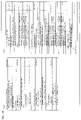
- FIG. 13 shows structures of a picture layer and subsequent layers in the encoded data # 4 .
- (a) to (d) of FIG. 13 show a picture layer defining a picture PICT, a slice layer defining a slice S, a tree block layer defining a tree block TBLK, and a CU layer defining a coding unit (CU) included in the tree block TBLK.
- a picture defining a picture PICT a slice layer defining a slice S
- a tree block layer defining a tree block TBLK
- CU coding unit
- the picture PICT includes a picture header PH and slices S 1 to S NS (NS indicates the total number of slices included in the picture PICT).
- the picture header PH includes encoding parameters to be referred to by the video decoding device 3 in order to determine a method for decoding a target picture.
- encoding mode information entropy_coding_mode_flag
- encoding mode information indicative of the mode of variable-length encoding which is used when the video encoding device 4 encodes is an example of an encoding parameter included in the picture header PH.
- the picture PICT is encoded by CAVLC (Context-based Adaptive Variable Length Coding).
- CABAC Context-based Adaptive Binary Arithmetic Coding
- the picture header PH is also referred to as a picture parameter set (PPS).
- PPS picture parameter set
- FIG. 16 is a view showing syntax included in the picture parameter set.
- the picture parameter set includes syntax log 2_min_delta_qualt_coding_unit_size_minus4.
- the video decoding device in accordance with the present embodiment generates MinDeltaQuantCodingUnitSize as size information by referring to the syntax.
- a Descriptor u( 1 ) shown in FIG. 16 indicates that syntax related to these descriptors is subjected to fixed codeword length coding by 1 bit, u( 2 ) indicates that syntax related to this descriptor is subjected to fixed codeword length coding by 2 bit, and ue(v) indicates that syntax related to this descriptor is subjected to variable codeword length coding (the same is applicable to a syntax table below).
- the slice layer a set of data to be referred to by the video decoding device 3 in order to decode a slice S to be processed (which may be also referred to as target slice) is defined.
- the slice S includes a slice header SH and tree blocks TBLK 1 to TBLK NC (NC indicates the total number of tree blocks included in the slice S).
- the slice header SH includes encoding parameters to be referred to by the video decoding device 1 in order to determine a method for decoding a target slice.
- Slice type designating information (slice_type) for designating a slice type is an example of an encoding parameter included in the slice header SH.
- Examples of the slice type that can be designated by the slice type designating information include (1) I slice which uses only intra-prediction in encoding, (2) P slice which uses single-direction prediction or intra-prediction in encoding, and (3) B slice which uses single-direction prediction, two-direction prediction, or intra-prediction.
- the slice header SH may include a filter parameter to be referred to by a loop filter (not shown) included in the video decoding device 1 .
- a set of data to be referred to by the video decoding device 3 in order to decode a tree block TBLK to be processed (which may be also referred to as a target tree block) is defined.
- the tree block TBLK includes a tree block header TBLKH and coding unit information CU 1 to CU NL (NL indicates the total number of coding unit information included in the tree block TBLK).
- NL indicates the total number of coding unit information included in the tree block TBLK.
- the tree block TBLK is divided into partitions for specifying the size of a block for intra-prediction or inter-prediction and transform processes.
- the partitions of the tree block TBLK are obtained by recursive quadtree division.
- a tree structure obtained by this recursive quadtree division is hereinafter referred to as a coding tree.
- a partition corresponding to a leaf which is a node at an end of the coding tree is referred to as a coding node. Since the coding node is a basic unit in a coding process, the coding node is hereinafter also referred to as a coding unit (CU).
- CU coding unit
- coding unit information (hereinafter referred to as CU information)
- CU 1 to CU NL is information corresponding to coding nodes (coding units) obtained by subjecting the tree block TBLK to recursive quadtree division.
- a root of the coding tree is made to correspond to the tree block TBLK.
- the tree block TBLK is made to correspond to a top node of a quadtree structure recursively including a plurality of coding nodes.
- each encoding node is a half both in vertical and horizontal directions of the size of an encoding node to which that coding node directly belong (i.e. partition of a node which is superior by one layer to that encoding node).
- the possible size of individual coding nodes depends on size designating information for a coding node and maximum hierarchical depth which are included in a sequence parameter set SPS of the encoded data # 4 .
- size designating information for a coding node and maximum hierarchical depth which are included in a sequence parameter set SPS of the encoded data # 4 .
- the size of a coding node at a layer of the tree block TBLK or below that layer can be one of three kinds of sizes: 64 ⁇ 64 pixels, 32 ⁇ 32 pixels, and 16 ⁇ 16 pixels.
- a tree block header TBLKH includes a coding parameter to be referred to by the video decoding device 3 in order to determine a method for decoding a target tree block.
- the tree block header TBLKH includes tree block dividing information SP_TBLK for designating a division pattern for individual CUs of the target tree block and a quantization parameter difference ⁇ qp (qp_delta) for designating the size of a quantization step.
- the tree block dividing information SP_TBLK is information indicative of a coding tree for dividing tree blocks. Specifically, the tree block dividing information SP_TBLK is information for designating the shape and the size of individual CUs included in the target tree block and the position of individual CUs in the target tree block.
- the tree block dividing information SP_TBLK is not required to explicitly include the shape and the size of a CU.
- the tree block dividing information SP_TBLK may be a set of flags indicative of whether a target tree block as a whole or a partial region of the tree block is to be subjected to quadtree division or not (split_coding_unit_flag).
- the shape and the size of each CU can be specified by using the shape and the size of the tree block.
- the quantization parameter difference ⁇ qp is a difference qp ⁇ qp′ between a quantization parameter qp in the target tree block and a quantization parameter qp′ in a tree block which has been encoded just before the target tree block.
- a set of data to be referred to by the video decoding device 3 in order to decode a CU to be processed (which is hereinafter also referred to as a target CU) is defined.
- the coding node serves as a root node of a prediction tree (PT) and a transform tree (TT). The following explains the prediction tree and the transform tree.
- PT prediction tree
- TT transform tree
- a coding node is divided into one or a plurality of prediction blocks, and the positions and the sizes of individual prediction blocks are defined.
- the prediction block is one or a plurality of non-overlapping regions constituting the coding node.
- the prediction tree includes one or a plurality of prediction blocks obtained by the above division.
- a prediction process is carried out with respect to each prediction block.
- the prediction block serving as a unit of prediction is also referred to as a prediction unit (PU).
- the division may be made based on 2N ⁇ 2N (the same size as that of the coding node) or N ⁇ N.
- the division may be made based on 2N ⁇ 2N (the same size as that of the coding node), 2N ⁇ N, N ⁇ 2N, N ⁇ N or etc.
- a coding node is divided into one or a plurality of transform blocks, and the positions and the sizes of individual transform blocks are defined.
- the transform block is one or a plurality of non-overlapping regions constituting the coding node.
- the transform tree includes one or a plurality of transform blocks obtained by the above division.
- Division in the transform tree includes assigning a region with a size equal to that of the coding node as a transform block, and recursive quadtree division like the division in the tree block.
- transform block serving as a unit of transform
- TU transform unit
- the CU information includes a skip flag SKIP, PT information PTI, and TT information TTI.
- the skip flag SKIP is a flag for showing whether a skip mode is applied to a target PU or not.
- the skip flag SKIP is 1, i.e. the skip mode is applied to a target CU, the PT information PTI and the TT information TTI in the CU information are omitted.
- the skip flag SKIP is omitted in the I slice.
- the PT information PTI is information regarding PT in CU.
- the PT information PTI is a set of information regarding one or a plurality of PUs included in PT and is referred to by the video decoding device 3 when generating a prediction image.
- the PT information PTI includes prediction type information PType and prediction information PInfo.
- the prediction type information PType is information for designating use of intra-prediction or use of inter-prediction as a method for generating a prediction image for a target PU.
- the prediction information PInfo is constituted by intra-prediction information or inter-prediction information according to which prediction method the prediction type information PType designates.
- PU to which intra-prediction is applied is also referred to as intra PU
- PU to which inter-prediction is applied is also referred to as inter PU.
- the prediction information PInfo includes information for designating the shape, the size, and the position of a target PU. As described above, the prediction image is generated with respect to each PU as a unit.
- the prediction information PInfo is detailed later.
- the TT information TTI is information regarding TT included in CU.
- the TT information TTI is a set of information regarding one or a plurality of TUs included in TT, and is referred to by the video decoding device 1 when decoding residual error data.
- TU is also referred to as a block.
- the TT information TTI includes TT division information SP_TT for designating a division pattern for individual transform blocks in a target CU, and quantization prediction residual errors QD 1 to QD NT (NT indicates the total number of blocks included in the target CU).
- the TT division information SP_TT is information for determining the shape and the size of individual TUs included in the target CU and the position of individual TUs in the target CU.
- the TT division information SP_TT can be realized by including information indicative of whether to divide a target node or not (split_transform_unit_flag) and information indicative of the depth of the division (trafoDepth).
- the size of individual TUs obtained by division can range from 32 ⁇ 32 pixels to 2 ⁇ 2 pixels.
- the quantization prediction residual error QD is coding data generated by the video encoding device 4 carrying out processes 1 to 3 below on a target block to be processed.
- Process 2 transform coefficient obtained in the process 1 is quantized
- Process 3 transform coefficient quantized in the process 2 is subjected to variable codeword length coding.
- the prediction information PInfo there are two kinds of the prediction information PInfo: the inter-prediction information and the intra-prediction information.
- the inter-prediction information includes a coding parameter to be referred to by the video decoding device 3 when generating an inter-prediction image by inter-prediction.
- the inter-prediction information includes inter PU division information for designating a division pattern for individual inter PUs of a target CU and inter-prediction parameters for individual inter PUs.
- the inter-prediction parameter includes a reference image index, an estimated motion vector index, and motion vector residual error.
- the intra-prediction information includes a coding parameter to be referred to by the video decoding device 3 when generating an intra-prediction image by intra-prediction.
- the intra-prediction information includes intra-PU division information for designating a division pattern for individual intra-PUs of a target CU and intra-prediction parameters for individual intra-PUs.
- the intra-prediction parameter is a parameter for designating an intra-prediction method (prediction mode) for individual intra-PUs.
- TU indicates a transform block at the bottom node of a transform tree.
- LCU indicates a CU at the top node of a coding tree.
- the video decoding device in accordance with the present embodiment is a device for decoding the encoded data # 4 from the video encoding device 4 (which will be explained below) to generate the decoded image # 3 .
- FIG. 14 is a block diagram showing the configuration of the video decoding device 3 .
- the video decoding device 3 includes a variable-length code inverse-multiplexing section 31 , a side information decoding section 32 , a CU setting section 33 , a CU decoding section 34 , and a frame memory 15 .
- the encoded data # 4 inputted to the video decoding device 3 is inputted to the variable-length code inverse-multiplexing section 31 .
- the variable-length code inverse-multiplexing section 31 reverse-multiplexes the input encoded data # 4 so as to divide the encoded data # 4 into side information encoded data # 31 a which is encoded data regarding side information and encoded data # 31 b which is encoded data regarding a picture, and outputs the side information encoded data # 31 a and the encoded data # 31 b to the side information decoding section 32 and the CU setting section 33 , respectively.
- the side information decoding section 32 decodes the side information encoded data # 31 a to generate side information # 32 , and outputs the side information # 32 to the CU setting section 33 .
- the side information decoding section 32 decodes encoded data of a QP difference value of each QP encoding unit region, thereby generating the QP difference value as a part of the side information # 32 .
- the side information decoding section 32 sequentially carries out a process below on individual CUs by referring to a coding_unit syntax (see FIG. 18 ) included in the encoded data # 4 . That is, when x-component and y-component of the upper left coordinates of a CU for which a skip flag (skip_flag) is to be referred to are equal to integer multiples of the size of a QP encoding unit region (MinDeltaQuantCodingUnitSize), the side information decoding section 32 sets a value of a flag indicative of whether decodable or not (deltaQuantAvail) to “true” indicative of a decodable state.
- a coding_unit syntax see FIG. 18
- the side information decoding section 32 decodes the QP difference value at a time of decoding a CU other than the skip block while deltaQuantAvail indicates a decodable state. That is, when referring to a skip flag “0” while deltaQuantAvail is “true”, the side information decoding section 32 decodes cu_qp_delta included in the coding_unit syntax, and sets the QP difference value of a CU for which the skip flag has been referred to to the value of decoded cu_qp_delta. Subsequently, the side information decoding section 32 sets the value of deltaQuantAvail to “false”.
- the side information decoding section 32 refers to a skip flag whose value is “0”, and sets 0 to the QP difference value.
- the value of qp at CU decoded immediately before the CU for which the skip flag was referred to is used as qp for the CU for which the skip flag was referred to.
- cu_qp_delta may be decoded as follows.
- the side information decoding section 32 may refer to a skip flag of the CU and a merge flag of the CU in raster scan order.
- the side information decoding section 32 decodes, from cu_qp_delta, a QP difference value of a CU for which skip flag “0” and merge flag “0” are referred to firstly in the QP encoding unit region.
- the side information decoding section 32 may sequentially carry out a process below on individual CUs by referring to a coding_unit syntax (see FIG. 19 ) included in the encoded data # 4 . That is, when x-component and y-component of the upper left coordinates of a CU for which a skip flag (skip_flag) is to be referred to are equal to integer multiples of the size of a QP encoding unit region (MinDeltaQuantCodingUnitSize), the side information decoding section 32 sets a value of a flag indicative of whether decodable or not (deltaQuantAvail) to “true” indicative of a decodable state.
- a coding_unit syntax see FIG. 19
- the side information decoding section 32 decodes cu_qp_delta at a time of decoding a CU which is neither a skip block nor a merge block. That is, when referring to both a skip flag “0” and a merge flag “0” while deltaQuantAvail is “true”, the side information decoding section 32 decodes cu_qp_delta included in the coding_unit syntax, and sets the QP difference value of a CU for which the skip flag has been referred to to the value of decoded cu_qp_delta. Subsequently, the side information decoding section 32 sets the value of deltaQuantAvail to “false”.
- the side information decoding section 32 does not encode a QP difference value at the time of decoding a CU of a skip block or a merge block while deltaQuantAvail indicates “false”. That is, when referring to a skip flag “1” while deltaQuantAvail indicates “false”, or when referring to both a skip flag “0” and a merge flag “1” while deltaQuantAvail indicates “false”, the side information decoding section 32 sets the QP difference value to 0. In this case, the value qp of a CU decoded immediately before the CU for which the skip flag is referred to is used as qp for the CU for which the skip flag is referred to.
- qp is set uniquely for each QP encoding unit region.
- qp set uniquely for each QP encoding unit region is used in common among CUs included in the QP encoding unit region.
- the CU setting section 33 divides the encoded data # 31 b into a plurality of slices, divides each slice into a plurality of QP encoding unit regions, separates each QP encoding unit region into encoded data # 33 b corresponding to individual CUs, and outputs the encoded data # 33 b sequentially to the CU decoding section 34 . Furthermore, the CU setting section 33 outputs, to the CU decoding section 34 , a QP difference value # 33 a of each QP encoding unit region included in the side information # 32 as well as the encoded data # 33 b corresponding to individual CUs in the QP encoding unit region.
- the CU decoding section 34 sequentially decodes and reverse-quantizes the encoded data # 33 b corresponding to inputted individual CUs (reverse-quantized unit region) to generate decoded images # 34 corresponding to individual CUs and outputs the decoded images # 34 .
- the decoded images # 34 are outputted to the frame memory 15 , too.
- the CU decoding section 34 when decoding and reverse-quantizing the encoded data # 33 b corresponding to a CU, the CU decoding section 34 obtains a QP value from the QP difference value # 33 a of the QP encoding unit region to which the CU belongs, and carries out an inverse-quantization process.
- the video decoding device decodes encoded data of a QP difference value not with respect to each CU but with respect to each QP encoding unit region consisting of one or more CUs, and accordingly can generate a decoded image from encoded data with the smaller amount of codes than a conventional art.
- a skip block which is a CU without residual error data does not require qp.
- the skip flag is “1”
- the QP difference value is not decoded, and only when the skip flag is “0”, the QP difference value is decoded. This allows reducing the amount of codes of the QP difference value in encoded data.
- Video Coding Device Video Coding Device
- a video encoding device in accordance with the present embodiment carries out a process of dividing each LCU constituting the input image into a plurality of CUs (Coding Unit: quantization unit region) by using a coding_tree syntax described in JCTVT-403.
- the dividing process is specifically a recursive process of dividing a CU at an i th node into four CUs at an i+1 th node with a one-fourth size when split_coding_unit_flag of a CU at the i-th node is true. Therefore, the sizes of the plurality of CUs are not identical with each other in general.
- the video encoding device is designed to encode, with respect to each QP encoding unit region (unit region) consisting of one or more CUs, a QP difference value regarding one CU at most belonging to the QP encoding unit region. Furthermore, the video encoding device is designed to encode size information indicative of the size of the QP encoding unit region.
- the video encoding device in accordance with the present embodiment does not encode a QP difference value with respect to each quantization unit region like the video encoding device in accordance with First Embodiment, but encodes a QP difference value with respect to each QP encoding unit region consisting of one or more quantization unit regions, thereby reducing the amount of codes of the QP difference value.
- the thus encoded QP difference value of each QP encoding unit region and the thus encoded size information of each QP encoding unit region are transmitted to a later-mentioned video decoding device. Then, the video decoding device carries out inverse-quantization using a QP difference value common among quantization unit regions constituting one QP encoding unit region.
- a region (third unit region) constituting the QP encoding unit region may be TU instead of CU.
- FIG. 15 is a block diagram showing a configuration of the video encoding device 4 .
- the video encoding device 4 includes a side information determination section 41 , a side information encoding section 42 , a CU setting section 43 , a CU encoding section 44 , a variable-length code multiplexing section 25 , a CU decoding section 46 , and a frame memory 27 .
- the side information determination section 41 determines side information in accordance with an input image # 100 , and outputs the determined side information as side information # 41 .
- the side information # 41 (and later-mentioned side information # 61 , # 81 etc. as well) includes a picture parameter set # 7 which is a set of parameters regarding the input image # 100 , a slice header which is header information with respect to each slice included in the input image # 100 , CU information which is a set of parameters with respect to each CU included in a slice, TU information which is a set of parameters with respect to each TU included in a CU etc.
- the side information determination section determines the (longitudinal and lateral) size of a QP encoding unit region in accordance with a predetermined algorithm with respect to each slice (or each picture), and causes size information indicative of the size of the QP encoding unit region to be stored in a slice header (picture parameter set) of the side information # 41 .
- the side information determination section 41 defines a QP encoding unit region constituting the input image # 100 (or each slice) in accordance with size information for the QP encoding unit region in the picture parameter set (or slice header), and causes a QP difference value regarding one CU at most per each QP encoding unit region (hereinafter also referred to merely as “QP difference value of a QP encoding unit region”) to be stored as a part of CU information of the CU in the side information # 41 .
- the side information encoding section 42 encodes the side information # 41 and outputs side information encoded data # 42 .
- the side information encoded data # 42 is supplied to the variable-length code multiplexing section 25 .
- the side information encoding section 42 encodes a QP difference value of each QP encoding unit region and the size information.
- the side information encoding section 42 applies logarithmic function having 2 as a base to the size of a QP encoding unit region to obtain a logarithmic function value and subtracts 4 from the logarithmic function value, thereby generating encoded data of size information.
- encoded data of the picture parameter set is data shown in FIG. 16 for example (in FIG. 16 , log 2_min_delta_qualt_coding_unit_size_minus4 indicates encoded data of size information).
- the CU setting section 43 divides the input image # 100 into a plurality of slices in accordance with the side information # 41 , and divides each slice into a plurality of CUs, and outputs CU images # 43 regarding individual CUs. As mentioned above, individual CU images have different sizes in general.
- the CU setting section 43 outputs CU images # 43 b regarding a plurality of CUs constituting one QP encoding unit region and a QP difference value # 43 a of the QP encoding unit region which is stored in the side information # 41 .
- the CU encoding section 44 carries out DCT transformation of predictive residuals between sequentially input CU images # 43 b and a predicted image transmitted from a predicted image generation section (not shown) and quantizes DCT coefficients of the predictive residuals at quantization levels corresponding to QP values determined according to QP difference values # 43 a of QP encoding unit regions to which the CU images # 43 b belong. Then, the CU encoding section 44 subjects the data obtained by quantization to a variable-length encoding process to generate CU encoded data # 44 and supplies the CU encoded data # 44 to the variable-length code multiplexing section 25 .
- the CU decoding section 46 sequentially decodes the CU encoded data # 44 corresponding to inputted CU images # 43 b , respectively, thereby generating and outputting decoded images # 46 corresponding to CUs, respectively.
- the decoded images # 46 are supplied to the frame memory 27 .
- variable-length code multiplexing section 25 and the frame memory 27 have been already explained in First Embodiment and therefore explanations thereof are omitted here.
- FIG. 17 is a view schematically showing a part of a QP encoding unit region (four QP encoding unit regions) defined by the side information determination section 41 .
- Each of four square regions surrounded by a thick line in FIG. 17 is a QP encoding unit region, and twelve regions surrounded by a thin line is a CU.
- a CU with hatched lines is a CU whose QP difference value is to be encoded, and a CU with dots is a skip block.
- the side information determination section 41 refers to, in a predetermined order (in the raster scan order in the present embodiment), a skip flag of each of at least one CU constituting the whole of each QP encoding unit region defined by the side information determination section 41 .
- the side information determination section 41 calculates a QP value of a CU for which a skip flag “0” is referred to firstly in the QP encoding unit region, and outputs, as a part of the side information # 41 , a QP difference value between the QP value of that CU and a QP value referred to immediately before the QP value of that CU (or default QP value) to the side information encoding section 42 .
- the side information determination section 41 calculates the QP value of a CU with hatched lines positioned secondly in the raster scan order, and outputs a QP difference value between the QP value of that CU and a default QP value to the side information encoding section 42 .
- the side information encoding section 42 encodes, with respect to each QP encoding unit region, a QP difference value of one CU at most in the QP encoding unit region.
- the QP difference value is stored in the side information # 41 .
- the side information determination section 41 and the side information encoding section 42 sequentially subject individual CUs to a process below by using a coding unit syntax shown in FIG. 18 . That is, when x-component and y-component of the upper left coordinates of a CU whose skip flag (skip_flag) is referred to are integer-multiples of the size of the QP encoding unit region (MinDeltaQuantCodingUnitSize), the side information determination section 41 sets the value of a flag indicative of whether encoding is possible or not (deltaQuantAvail) to “true”.
- the side information determination section 41 supplies, as a part of the side information # 41 , the QP difference value of the CU whose skip flag has been referred to, to the side information encoding section 42 .
- the side information encoding section 42 subjects the QP difference value to an encoding process and sets the value of deltaQuantAvail to “false”.
- the side information determination section 41 may refer to a skip flag and a merge flag of each of at least one CU constituting the whole of each QP encoding unit region defined by the side information determination section 41 .
- the side information determination section 41 calculates a QP value of a CU for which a skip flag “0” and a merge flag “0” are referred to firstly in the QP encoding unit region, and outputs, as a part of the side information # 41 , a QP difference value between the QP value of that CU and a QP value referred to immediately before the QP value of that CU (or default QP value) to the side information encoding section 42 .
- the side information determination section and the side information encoding section 42 may sequentially subject individual CUs to a process below by using a coding unit syntax shown in FIG. 19 . That is, when x-component and y-component of the upper left coordinates of a CU whose skip flag (skip_flag) is referred to are integer-multiples of the size of the QP encoding unit region (MinDeltaQuantCodingUnitSize), the side information determination section 41 sets the value of a flag indicative of whether encoding is possible or not (deltaQuantAvail) to “true”.
- the side information determination section 41 supplies, as a part of the side information # 41 , the QP difference value of the CU whose skip flag has been referred to, to the side information encoding section 42 .
- the side information encoding section 42 subjects the QP difference value to an encoding process and sets the value of deltaQuantAvail to “false”.
- variable-length code multiplexing section 25 receives, from the side information encoding section 42 , side information encoded data # 42 including encoded data of QP difference values of individual QP encoding unit regions and size information of the QP encoding unit regions determined with respect to each picture parameter set (each slice). Furthermore, the variable-length code multiplexing section 25 multiplexes CU encoded data # 44 received from the CU encoding section 44 and the side information encoded data # 42 to generate and output encoded data # 4 .
- the side information determination section 41 may cause size information of the QP encoding unit region to be stored in a sequence parameter set instead of a slice header and a picture parameter set.
- the side information encoding section 42 of the video encoding device 4 applies logarithmic function having 2 as a base to the size of a QP encoding unit region to obtain a logarithmic function value and subtracts 4 from the logarithmic function value.
- the present invention is not limited to this.
- the side information encoding section 42 may encode the size of a QP encoding unit region relative to the size of an LCU. For example, in a case where the size of a QP encoding unit region is one-2n of the size of an LCU (max_coding_unit_width), the side information encoding section 42 may generate n as encoded data for size information.
- the side information decoding section 32 of the video decoding device 3 subjects log 2_min_delta_qualt_coding_unit_size_to_lcu included in the side information encoded data # 31 a to an operation based on formula 2 below, and generates MinDeltaQuantCodingUnitSize as the size information.
- MinDeltaQuantCodingUnitSize max_coding_unit_width>>log 2_min_delta_quant_unit_size_to_lcu Formula 2
- the method for encoding the size of a QP encoding unit region as a size relative to the size of an LCU is applicable to embodiments below.
- a configuration of encoded data # 6 in accordance with the present embodiment is substantially the same as the configuration of the encoded data # 4 explained in Second Embodiment except that the encoded data # 6 in accordance with the present embodiment includes a coding_unit syntax shown in FIG. 20 and a transform_tree syntax shown in FIG. 21 .
- the coding_unit syntax shown in FIG. 20 and the transform_tree syntax shown in FIG. 21 will be explained together with a video decoding device and a video encoding device below.
- the video decoding device in accordance with the present embodiment has substantially the same configuration as that of the video decoding device 3 explained in Second Embodiment.
- the video decoding device in accordance with the present embodiment operates in basically substantially the same manner as the video decoding device 3 explained in Second Embodiment, thereby decoding the encoded data # 6 to generate a decoded image # 3 .
- a QP difference value of each QP encoding unit region is not a part of QP information of the side information # 32 , but a part of TU information of the side information # 32 .
- a CU setting section 33 of the video decoding device 3 refers to TU information of each selection target TU which is included in the side information # 32 , thereby reading out a QP difference value of each QP encoding unit region.
- a side information decoding section 32 included in the video decoding device in accordance with the present embodiment refers to, in the raster scan order, a skip flag and a residual data present flag (residualDataPresentFlag) of each of at least one CU constituting the whole of each QP encoding unit region.
- the residual data present flag is a flag that becomes “true” when a CU includes at least one TU including at least one DCT coefficient which is not 0, and becomes “false” when otherwise.
- the side information decoding section 32 sequentially subjects individual CUs to a process below. That is, as is seen from FIG. 20 , when x-component and y-component of the upper left coordinates of a CU whose skip flag (skip_flag) is referred to are integer-multiples of the longitudinal and lateral size of a QP encoding unit region (MinDeltaQuantCodingUnitSize), the side information decoding section 32 sets the value of a flag indicative of whether decoding is possible or not (deltaQuantAvail) to “true”.
- the side information decoding section 32 refers to a skip flag “0” while the value of deltaQuantAvail is “true”, the side information decoding section 32 refers to the value of residualDataPresentFlag in the transform_tree syntax shown in FIG. 21 .
- the value of residualDataPresentFlag is “0”, that is, when the TU does not include residual data
- the side information decoding section 32 refers to the coding unit syntax with respect to next CU.
- residualDataPresentFlag is determined depending on whether the value of cuv_yuv_root is or not.
- cuv_yuv_root is other than 0, residualDataPresentFlag is “true”, and when cuv_yuv_root is 0, residualDataPresentFlag is “false”.
- residualDataPresentFlag is “true” if no_resisulal_data_flag is other than 0, and residualDataPresentFlag is “false” if no_resisulal_data_flag is 0.
- the side information decoding section 32 refers to the transform_tree syntax shown in FIG. 21 with respect to each TU constituting a CU of interest. Consequently, the side information decoding section 32 decodes cu_qp_delta of a TU (e.g. TU at the lower right end.
- selection target TU which includes at least one DCT coefficient other than 0 and which is firstly decoded in a predetermined order (e.g.
- the side information decoding section 32 sets the value of deltaQuantAvail to “false”.
- the above process by the side information decoding section 32 uniquely determines qp with respect to each QP encoding unit region. qp uniquely determined with respect to each QP encoding unit region is used commonly for CUs included in the QP encoding unit region.
- the video encoding device in accordance with the present embodiment divides each LCU constituting an input image into a plurality of CUs (Coding Unit: quantization unit region) by using a coding_tree syntax. Furthermore, unlike the video encoding device 4 , the video encoding device in accordance with the present embodiment divides each CU into a plurality of transform units (TU) constituting a transform tree by using the coding_unit syntax shown in FIG. 20 and the transform_tree syntax shown in FIG. 21 .
- TU transform units
- the video encoding device is designed to encode only at least a part of TUs constituting the whole of each QP encoding unit region determined according to a predetermined algorithm constituted by one or more TUs mentioned above. It should be noted that the video encoding device in accordance with the present embodiment encodes the QP difference value of the TU only when predictive residual of the TU is other than 0 (i.e. when a DCT coefficient other than 0 is present). Absence of the DCT coefficient other than 0 is equal to DCT coefficients of luminance components being 0 and DCT coefficients of color difference components of the TU being 0. Accordingly, unlike Second Embodiment, the video encoding device in accordance with the present embodiment can reduce a redundant process of encoding a QP difference value which is not necessary to encode.
- FIG. 22 is a block diagram showing a configuration of the video encoding device 6 .
- the video encoding device 6 includes a side information determination section 61 , a side information encoding section 62 , a CU setting section 43 , a CU encoding section 44 , a variable-length code multiplexing section 25 , a CU decoding section 46 , and a frame memory 27 .
- the CU setting section 43 , the CU encoding section 44 , the variable-length code multiplexing section 25 , the CU decoding section 46 , and the frame memory 27 have been already explained in First Embodiment or Second Embodiment. Accordingly, an explanation is made below as to the side information determination section 61 and the side information encoding section 62 .
- the side information determination section 61 refers to a skip flag of the CU and a residual data present flag (residualDataPresentFlag) of the CU in the raster scan order.
- the residual data present flag is a flag which becomes “true” when a CU includes at least one TU including at least one DCT coefficient other than 0 and which becomes “false” when otherwise.
- the side information determination section 61 outputs, as a part of side information # 61 , a QP difference value # 63 a between a QP value of a CU whose skip flag “0” and residual data present flag “1” are referred to simultaneously for the first time in the QP encoding unit region and a default QP value, to the side information encoding section 62 .
- the side information encoding section 62 encodes the QP difference value received from the side information determination section 61 to generate encoded data # 62 .
- the side information determination section 61 and the side information encoding section 62 sequentially subject individual CUs to a process below. That is, as is seen from FIG. 20 , when x-component and y-component of the upper left coordinates of a CU whose skip flag (skip_flag) is referred to are integer-multiples of the longitudinal and lateral size of a QP encoding unit region (MinDeltaQuantCodingUnitSize), the side information determination section 61 sets the value of a flag indicative of whether encoding is possible or not (deltaQuantAvail) to “true”.
- the side information determination section 61 when the side information determination section 61 refers to a skip flag “0” while the value of deltaQuantAvail is “true”, the side information determination section 61 brings up the transform_tree syntax shown in FIG. 21 and refers to the value of residualDataPresentFlag. When the value of residualDataPresentFlag is the side information determination section 61 brings up the coding unit syntax with respect to the next CU.
- the side information determination section 61 calculates a QP difference value of a TU (e.g. TU at the lower right end.
- selection target TU which includes at least one DCT coefficient other than 0 and which is firstly referred to in a predetermined order (e.g. order opposite to raster scan order) out of TUs in the CU of interest, and supplies the QP difference value of the selection target TU as a part of TU information to the side information encoding section 62 .
- the side information encoding section 62 subjects the received QP difference value to an encoding process and sets the value of deltaQuantAvail to “false”.
- variable-length code multiplexing section 25 receives, from the side information encoding section 62 , side information encoded data # 62 including encoded data of QP difference values of individual QP encoding unit regions and size information of the QP encoding unit regions determined with respect to each picture (or each slice constituting the picture). Furthermore, the variable-length code multiplexing section 25 multiplexes CU encoded data # 44 received from the CU encoding section 44 and the side information encoded data # 62 to generate and output encoded data # 6 .
- the side information determination section 61 and the side information encoding section 62 may use a transform_tree syntax shown in FIG. 23 instead of the transform_tree syntax shown in FIG. 21 .
- the side information determination section 61 supplies not only the QP difference value of the selection target TU but also the QP difference value of the TU which includes at least one DCT coefficient other than 0 and which is at the upper left end in the CU of interest as a part of TU information to the side information encoding section 62 .
- the side information determination section 61 and the side information encoding section 62 may use a transform_tree syntax shown in FIG. 24 instead of the transform_tree syntax shown in FIG. 21 .
- the side information determination section 61 may supply, as a part of CU information of the CU (i.e. TU at the uppermost node), the QP difference value of the CU to the side information encoding section 62 .
- a video decoding device in accordance with the present embodiment is a device for decoding encoded data # 8 supplied from a video encoding device 8 to generate decoded images # 7 .
- An example of a coding unit syntax included in encoded data # 7 is shown in FIG. 27 .
- FIG. 27 is a block diagram showing the configuration of a video decoding device 7 .
- the video decoding device 7 includes a variable-length code inverse-multiplexing section 71 , a side information decoding section 72 , a CU setting section 73 , a CU decoding section 74 , a predicted image generation section 75 , and a frame memory 15 .
- the encoded data # 8 inputted to the video decoding device 7 is inputted to the variable-length code inverse-multiplexing section 71 .
- the variable-length code inverse-multiplexing section 71 reverse-multiplexes the inputted encoded data # 8 so as to divide the encoded data # 7 into side information encoded data # 71 a which is encoded data regarding side information and encoded data # 71 b which is encoded data regarding a picture, and outputs the side information encoded data # 71 a and the encoded data # 71 b to the side information decoding section 72 and the CU setting section 73 , respectively.
- the side information decoding section 72 decodes the side information encoded data # 71 a to generate side information # 72 and outputs the side information # 72 to the CU setting section 73 .
- the side information decoding section 72 decodes encoded data of a prediction mode # 88 m of each CU, thereby generating the prediction mode # 88 m of each CU which serves as a part of side information # 72 .
- the side information decoding section 72 decodes encoded data of size information of a first QP encoding unit region (unit region) and a second QP encoding unit region (fourth unit region) which data is included in the side information encoded data # 71 a , thereby generating the two pieces of size information as a part of the side information # 72 .
- the side information decoding section 72 subjects log 2_min_delta_qualt_coding_unit_size_minus4 to an operation based on the formula 1 above, thereby generating MinDeltaQuantCodingUnitSize as size information of the first QP encoding unit region.
- the side information decoding section 72 subjects log 2_min_intra_delta_qualt_coding_unit_size_minus4 included in the side information encoded data # 71 a to the MinIntraDeltaQuantCodingUnitSize as size information of the second QP encoding unit region.
- the side information decoding section 72 refers to the coding unit syntax shown in FIG. 27 and sequentially subjects individual CUs to a process below. That is, as is seen from FIG. 27 , when x-component and y-component of the upper left coordinates of a CU whose skip flag (skip_flag) is referred to are equal to integer-multiples of the size of the first QP encoding unit region (MinDeltaQuantCodingUnitSize), the side information decoding section 72 sets the value of deltaQuantAail to “true”.
- the side information decoding section 72 refers to the values of individual skip flags, and when referring to a skip flag “0”, the side information decoding section 72 sets a flag indicative of whether a QP difference value is decodable or not when a CU image is intra-coded (deltaQuantAvailIntra) to “true”. Furthermore, when referring to the skip flag “0” of a CU while the value of deltaQuantAvail is “true”, the side information decoding section 72 decodes cu_qp_delta included in the coding_unit syntax, and sets the value of decoded cu_qp_delta as the QP difference value of the CU whose skip flag has been referred to. Then, the side information decoding section 72 sets the values of deltaQuantAvail and deltaQuantAvailIntra to “false”.
- the side information decoding section 72 decodes cu_qp_delta included in the coding_unit syntax, and sets the value of decoded cu_qp_delta as the QP difference value of the CU whose skip flag has been referred to.
- the CU setting section 73 divides the encoded data # 71 b into a plurality of slices and divides each slice into encoded data # 73 b corresponding to individual CUs, and sequentially outputs the encoded data # 73 b to the CU decoding section 74 . Furthermore, the CU setting section 73 outputs, in addition to the encoded data # 73 b , prediction modes # 73 m of individual CUs and QP difference values 73 a of individual selection target CUs that are included in the side information # 72 to the CU decoding section 74 . Furthermore, the CU setting section 73 outputs the prediction modes # 73 m of individual CUs to the predicted image generation section 75 .
- the CU decoding section 74 sequentially decodes and reverse-quantizes the encoded data # 73 b corresponding to inputted CUs (inverse-quantization unit region), respectively, thereby generating and outputting decoded images # 74 corresponding to the CUs, respectively.
- the decoded images # 74 are also outputted to the frame memory 15 .
- the CU decoding section 74 refers to the sizes of the first QP encoding unit region and the second QP encoding unit region that are stored in the inputted side information # 72 , and defines individual QP encoding unit regions constituting the whole region of a decoded image to be generated.
- the CU decoding section 74 determines QP difference values used in inverse-quantization of individual CUs as follows. That is, when a CU to be reverse-quantized is a selection target CU, the CU decoding section 74 obtains a QP value of the selection target CU from the QP difference value # 73 b of the selection target CU which is received from the CU setting section 73 and a QP value of a CU reversely quantized immediately before. Then, the CU decoding section 74 carries out inverse-quantization at a quantization level corresponding to the QP value of the selection target CU.
- the CU decoding section 74 determines QP difference values used in inverse-quantization of the CU as follows. That is, when a prediction mode # 73 m of the CU which is received from the CU setting section 73 indicates an inter-prediction image, the CU decoding section 74 obtains a QP value of a CU to be reverse-quantized from a QP difference value # 73 b of a selection target CU in the first QP encoding unit region to which the CU belongs and a QP value of a CU reversely quantized immediately before. Then, the CU decoding section 74 carries out inverse-quantization at a quantization level corresponding to the QP value of the CU.
- the CU decoding section 74 obtains a QP value of a CU to be reverse-quantized from a QP difference value # 73 b of a selection target CU in the second QP encoding unit region to which the CU belongs and a QP value of a CU reversely quantized immediately before. Then, the CU decoding section 74 carries out inverse-quantization at a quantization level corresponding to the QP value of the CU.
- the CU decoding section 74 carries out inverse-quantization as above and carries out DCT reverse-transform to generate predictive residual. Then, the CU decoding section 74 adds the predicted image # 75 corresponding to the encoded data # 73 b which is received from the predicted image generation section 75 to the predictive residual to generate a decoded image # 74 .
- the predicted image generation section 75 In accordance with the prediction mode # 73 m transmitted from the CU setting section 73 , the predicted image generation section 75 generates an intra-predicted image from the decoded image # 74 stored in the frame memory 15 or calculates a motion vector using the reference image # 74 stored in the frame memory 15 and carries out motion compensation based on the motion vector to generate an inter-predicted image.
- the predicted image generation section 75 outputs the generated predicted image # 75 which is one of the intra-predicted image and the inter-predicted image.
- the video decoding device decodes encoded data of a QP difference value not with respect to each CU but with respect to only a selection target CU. Accordingly, it is possible to generate a decoded image from encoded data with a fewer amount of codes than a conventional video decoding device.
- the moving image encoding device in accordance with the present embodiment is designed such that as an input image includes a relatively larger number of regions to be inter-encoded, the moving image encoding device encodes a relatively smaller number of QP difference values. That is, as an input image includes a relatively larger number of regions to be intra-encoded, the moving image encoding device encodes a relatively larger number of QP difference values.
- FIG. 26 is a block diagram showing the configuration of the video encoding device 8 .
- the video encoding device 8 includes a side information determination section 81 , a side information encoding section 82 , a CU setting section 83 , a CU encoding section 84 , a variable-length code multiplexing section 25 , a CU decoding section 46 , a frame memory 27 , and a predicted image generating section 88 .
- An explanation is made here as to the side information determination section 81 , the side information encoding section 82 , and the predicted image generating section 88 .
- variable-length code multiplexing section 25 Since the variable-length code multiplexing section 25 , the CU decoding section 46 , and the frame memory 27 have been already explained in First or Second Embodiment, the following explains other members.
- the predicted image generating section 88 generates an intra-predicted image # 88 a from a decoded image # 46 stored in the frame memory 27 . Furthermore, the predicted image generating section 88 calculates motion vectors by using the reference image # 46 and carries out motion compensation based on the motion vectors, thereby generating an inter-predicted image # 88 b.
- the predicted image generating section 88 compares the intra-predicted image and the inter-predicted image with an input image # 100 , selects one of the intra-predicted image and the inter-predicted image, and outputs the selected image as a predicted image # 88 . Furthermore, the predicted image generating section 88 outputs a prediction mode # 88 m which is information indicating which of the intra-predicted image and the inter-predicted image is selected.
- the side information determination section 81 determines side information based on the input image # 100 and the prediction mode # 88 m regarding each CU, and outputs the determined side information as side information # 81 . Specifically, the side information determination section 81 determines, based on a predetermined algorithm with respect to each slice (or picture), the size of a first QP encoding unit region and the size of a second QP encoding unit region, and causes size information indicative of the sizes of the QP encoding unit regions to be stored in a slice header (picture parameter set) of the side information # 81 . Here, the side information determination section 81 determines the size of the first QP encoding unit region to be relatively larger than the size of the second QP encoding unit region.
- the side information determination section 81 determines the sizes of the first QP encoding unit region and the second QP encoding unit region in such a manner that the first QP encoding unit region (unit region) consists of a plurality of the second QP encoding unit regions (fourth unit region).
- the side information determination section 81 defines the first QP encoding unit region and the second QP encoding unit region constituting the input image # 100 (or individual slices) based on the size information of the first QP encoding unit region and the size of the second QP encoding unit region in the picture parameter set (or slice header), and causes a QP difference value of each CU selected by a later-mentioned process based on the prediction mode # 88 m (the CU is hereinafter also referred to as “selection target CU”) to be stored as a part of CU information of the CU in the side information # 81 . Furthermore, the side information determination section 81 causes the prediction mode # 88 m of the CUs to be stored in the side information # 81 .
- the side information encoding section 82 encodes the side information # 81 to output side information encoded data # 82 .
- the side information encoding section 82 encodes the QP difference values received from the side information determination section 81 .
- the encoded QP difference values constitute a part of the side information encoded data # 82 .
- the side information encoding section 82 encodes size information of the QP encoding unit regions.
- the encoded size information constitutes a part of the side information encoded data # 82 .
- the side information encoding section 82 applies a logarithmic function with base of 2 to the size of the QP encoding unit region and subtracts 4 from the resultant, thereby generating encoded data of the size information.
- the CU setting section 83 divides the input image # 100 into a plurality of slices, divides each slice into a plurality of CUs, and outputs CU images # 83 b regarding individual CUs.
- the CU setting section 83 outputs, with respect to a part of the CUs, not only CU images # 83 b of the part but also QP difference values # 83 of the part which are included in the side information # 81 .
- the CU encoding section 84 carries out DCT with respect to a prediction residual between sequentially inputted CU images 83 b and a predicted image transmitted from the predicted image generating section (not shown).
- the CU encoding section 84 quantizes DCT coefficients of the prediction residual at a quantization level corresponding to a QP value determined by a QP difference value # 83 a of a selection target CU in the first QP encoding unit region to which the CU image # 83 b belongs.
- the CU encoding section 84 quantizes DCT coefficients of the prediction residual at a quantization level corresponding to a QP value determined by a QP difference value # 83 a of a selection target CU in the second QP encoding unit region to which the CU image # 83 b belongs.
- the CU encoding section 84 outputs, to the variable-length code multiplexing section 25 , CU encoded data # 84 obtained by the above DCT and the quantization process.
- the side information determination section 81 refers to, in raster scan order, a skip flag of one or more CUs constituting the whole of each first QP encoding unit region.
- the CU setting section 83 calculates a QP difference value # 83 a which is a difference between a QP value of a CU whose skip flag of “0” is referred to for the first time in the first QP encoding unit region (selection target CU) and a default QP value.
- the side information determination section 81 is designed to judge whether the CU is positioned at the upper left end of the second QP encoding region and a prediction mode # 88 m for the CU that is transmitted from the predicted image generating section 88 is an intra-prediction mode (i.e. the result of the judgment process is true).
- the side information determination section 81 calculates the QP difference value # 83 a which is a difference between the QP value of the CU (selection target CU) and the QP default value.
- the side information determination section 81 supplies the QP difference value of each selection target CU to the CU setting section 83 and the side information encoding section 82 .
- the side information encoding section 82 encodes each QP difference value received from the side information determination section 81 , and generates encoded data of each QP difference value as a part of the encoded data # 82 .
- the side information determination section 81 and the side information encoding section 82 sequentially carries out a process mentioned below with respect to each CU by using a coding unit syntax shown in FIG. 27 . That is, as is seen from FIG. 27 , when x-component and y-component of the upper left coordinates of a CU whose skip flag (skip_flag) is referred to are equal to integer-multiples of the size of the first QP encoding unit region (MinDeltaQuantCodingUnitSize), the side information determination section 81 sets the value of deltaQuantAail to “true”.
- the side information determination section 81 refers to the value of each skip flag, and when referring to a skip flag whose value is “0”, the side information determination section 81 sets the flag indicative of whether a QP difference value is encodable or not in intra-encoding a CU image (deltaQuantAvailIntra) to “true”. Furthermore, when referring to a skip flag whose value is “0” while the value of deltaQuantAvail is “true”, the side information determination section 81 supplies, to the side information encoding section 82 , the QP difference value of the CU whose skip flag has been referred to, as a part of the side information # 81 .
- the side information encoding section 82 carries out an encoding process with respect to the QP difference value, and sets the values of deltaQuantAvail and deltaQuantAvailIntra to “false”.
- the side information determination section 81 supplies, to the side information encoding section 82 , the QP difference value of the CU whose skip flag has been referred to, as a part of the side information # 81 .
- the variable-length code multiplexing section 25 receives, from the side information encoding section 82 , side information encoded data # 82 including encoded data of i) the QP difference value of the selection target CU and ii) size information of the first QP encoding unit region and the second QP encoding unit region that is determined with respect to each picture (or each slice constituting a picture). Furthermore, the variable-length code multiplexing section 25 multiplexes CU encoded data # 84 received from the CU encoding section 84 with the side information encoded data # 82 , thereby generating encoded data # 8 and outputting it.
- the side information determination section 81 calls up the transform_tree syntax shown in FIG. 21 and refers to the value of residualDataPresentFlag.
- the side information determination section 61 calls up a coding unit syntax with respect to the next CU.
- x-component and y-component of the upper left coordinates of a CU are equal to integer-multiples of the size of a QP encoding unit region (MinDeltaQuantCodingUnitSize).
- a CU coordinates index shown below.
- the CU coordinates index is an index which indicates the position of a CU obtained by dividing an LCU as small as possible and which increases as 0, 1, 2 in the order of raster scan decoding from the upper left of the LCU.
- the side information determination section 81 determines a selection target CU according to the coding unit syntax shown in FIG. 27
- the side information encoding section 82 encodes a QP difference value of the selection target CU according to the coding unit syntax shown in FIG. 27
- the corresponding video image decoding device is designed such that the side information decoding section 72 decodes a QP difference value of the selection target CU according to the coding unit syntax shown in FIG. 27 .
- the present invention is not limited to this. That is, the side information determination section 81 may determine the selection target CU according to the coding unit syntax shown in FIG. 28 .
- the corresponding video image decoding device is designed such that the side information decoding section 72 decodes a QP difference value of the selection target CU according to the coding unit syntax shown in FIG. 28 .
- a syntax for carrying out a diverging process according to the prediction mode of a CU may be provided.
- cu_qp_delta to be referred to when the side information encoding section 82 encodes or the side information decoding section 72 decodes may be described at different positions depending on whether the prediction mode of a CU is an intra-prediction mode, an inter-prediction mode, a merge mode, or a direct mode (in other words, the step of encoding cu_qp_delta by the side information encoding section 82 may be a step following encoding of the prediction mode of a CU and may vary in whether encoding of cu_qp_delta is made depending on the kind of the prediction mode.
- the step of decoding cu_qp_delta by the side information decoding section 72 is a step following decoding of the prediction mode of a CU and may vary with respect to each prediction
- the present invention may be arranged such that in a case where the prediction mode is a skip mode, the QP difference value is not encoded, in a case where the prediction mode is an intra-prediction mode, the QP difference value is encoded only for a CU whose size is not less than MinIntraDeltaCodingUnitSize, and in a case where the prediction mode is neither the intra-prediction mode nor the skip mode, the QP difference value is encoded only for a CU whose size is not less than MinDeltaCodingUnitSize.
- a QP value (cu_qp) of a CU to be quantized is obtained by adding a QP value referred to immediately before (pred_qp) and a QP difference value of the CU to be quantized.
- the QP value referred to immediately before may be a QP value of a CU at the left side of the CU to be quantized, or may be a QP value of a CU positioned immediately before the CU to be quantized in the raster scan order.
- the QP value referred to immediately before may be the average of a QP value of a CU at the left side of the CU to be quantized and a QP value of a CU at the upper side of the CU to be quantized.
- a video decoding device in accordance with the present embodiment is a device for decoding encoded data # 10 from a video encoding device 10 (which will be explained below) to generate a decoded image # 9 .
- FIG. 31 shows an example of coding_unit syntax included in the encoded data # 10 .
- FIG. 29 is a block diagram showing the configuration of the video decoding device 9 .
- the video decoding device 9 includes a variable-length code inverse-multiplexing section 91 , a side information decoding section 92 , a CU setting section 93 , a CU decoding section 94 , and a frame memory 15 .
- the encoded data # 10 inputted to the video decoding device 9 is inputted to the variable-length code inverse-multiplexing section 91 .
- the variable-length code inverse-multiplexing section 91 reverse-multiplexes the input encoded data # 9 so as to divide the encoded data # 9 into side information encoded data # 91 a which is encoded data regarding side information and encoded data # 91 b which is encoded data regarding a picture, and outputs the side information encoded data # 91 a and the encoded data # 91 b to the side information decoding section 92 and the CU setting section 93 , respectively.
- the side information decoding section 92 decodes the side information encoded data # 91 a to generate side information # 92 , and outputs the side information # 92 to the CU setting section 93 .
- the side information decoding section 92 decodes encoded data of size information indicative of the size of a QP encoded unit region, thereby generating the size information as a part of the side information # 92 .
- the side information decoding section 92 decodes, for each LCU, encoded data of a QP difference value of each QP encoding unit region constituting the LCU or decodes encoded data of a QP difference value of the LCU, thereby generating the QP difference value as a part of the side information # 92 .
- the side information decoding section 92 decodes size information (MinDeltaQuantCodingUnitSize) included in a slice header (picture parameter set) of the encoded data # 10 so as to determine a (longitudinal and lateral) size of a QP encoding unit region.
- Size information MinDeltaQuantCodingUnitSize
- the side information decoding section 92 decodes a deltaQuantAvailCU flag of each LCU.
- the side information decoding section 92 determines to decode, per LCU, a QP difference value used in quantization of the LCU (decode one QP difference value at most in the LCU). Then, the side information decoding section 92 utilizes the QP difference value to decode each CU included in the LCU.
- the side information decoding section 92 determines to decode, per CU, a QP difference value used in quantization of the LCU. Then, the side information decoding section 92 decodes a QP difference value of a selection target CU. Note that one selection target CU at most is selected for each QP encoding unit region.
- the side information decoding section 92 carries out the following processes with respect to a target CU of each of at least one CU constituting a LCU.
- the side information decoding section 92 sets a deltaQuantAvailLCU flag to “true”.
- the side information decoding section 92 sets a deltaQuantAvail flag to “true”.
- the deltaQuantAvailLCU flag, the deltaQuantAvailCU flag, and the deltaQuantAvail flag have the following meanings.
- the deltaQuantAvailLCU flag is a flag for controlling encoding/decoding of the deltaQuantAvailCU flag encoded per LCU, and indicates whether the deltaQuantAvailCU can be encoded or decoded.
- the deltaQuantAvailCU flag is a flag for selecting whether a QP difference value is encoded per LCU or encoded per CU.
- the deltaQuantAvailCU flag becomes “false” in a case where a QP difference value is encoded per LCU, and becomes “true” in a case where a QP difference value is encoded per CU.
- the deltaQuantAvail flag is a flag for controlling a QP encoding unit in a case where a QP difference value is encoded per CU, and indicates whether qp_delta can be encoded or decoded.
- the side information decoding section 92 decodes qp_delta of the target CU (i.e., selection target CU), and sets decoded qp_delta as the QP difference value of the target CU. Moreover, the side information decoding section 92 decodes the deltaQuantAvailCU flag, and sets the deltaQuantAvailLCU flag to “false”. According to the syntax of FIG. 31 , the deltaQuantAvailCU flag follows qp_delta. Note, however, that it is also possible to employ a syntax in which the deltaQuantAvailCU flag is followed by qp_delta.
- the side information decoding section 92 decodes qp_delta of the target CU (i.e., selection target CU), and sets decoded qp_delta as the QP difference value of the target CU. Further, the side information decoding section 92 sets the deltaQuantAvail flag to “false”.
- the deltaQuantAvail flag cannot be “true” as long as the deltaQuantAvailCU flag of an LCU is “false”. Accordingly, a QP difference value of a single CU in which a skip flag “0” is referred to first in raster scan order in an LCU is decoded. Consequently, in a case where the deltaQuantAvailCU flag is “false”, a QP difference value is decoded per LCU.
- the deltaQuantAvailCU flag of the LCU is “true”
- the deltaQuantAvail flag becomes “true” every time the coding_unit syntax of FIG. 31 is applied to the target CU located on the upper left end of the QP encoding unit region. Accordingly, a QP difference value of a selection target CU is decoded. Note that one selection target CU at most is selected for each QP encoding unit region.
- the CU setting section 93 divides the encoded data # 91 b into a plurality of slices, divides each slice into a plurality of QP encoding unit regions, separates each QP encoding unit region into encoded data # 93 b corresponding to individual CUs, and outputs the encoded data # 93 b sequentially to the CU decoding section 94 .
- the CU setting section 93 refers to the deltaQuantAvailCU flag for each LCU.
- the deltaQuantAvailCU flag is a flag indicative of whether a QP difference value is encoded per LCU or an LCU is encoded per QP encoding region unit.
- the CU setting section 93 refers to CU information of each CU belonging to the LCU and, as to CUs whose CU information contains a QP difference value, outputs the QP difference value to the CU decoding section 94 .
- the CU setting section 93 outputs, to the CU decoding section 94 , a QP difference value contained in CU information of the LCU.
- the CU setting section 93 outputs, to the CU decoding section 94 , the deltaQuantAvailCU flag of each LCU.
- the CU decoding section 94 sequentially decodes and reverse-quantizes the encoded data # 93 b corresponding to inputted CUs (inverse-quantization unit region), respectively, thereby generating and outputting decoded images # 94 corresponding to the CUs, respectively.
- the decoded images # 94 are also outputted to the frame memory 15 .
- the CU decoding section 94 obtains, in accordance with a value of the deltaQuantAvailCU flag of an LCU to which the CU belongs, a QP value from a QP difference value # 93 a of a QP encoding unit region to which the CU belongs or from a QP difference value # 93 a of the LCU, and carries out the inverse-quantization in accordance with the QP value.
- the video decoding device decodes encoded data of a QP difference value not with respect to each CU but with respect to each LCU unit or each QP encoding unit region constituting an LCU, and accordingly can generate a decoded image from encoded data with the smaller amount of codes than a conventional art.
- a video encoding device in accordance with the present embodiment carries out a process of dividing each LCU constituting the input image into a plurality of CUs (Coding Unit: quantization unit region) by using a coding_tree syntax described in JCTVC-C403, as in the video encoding device in accordance with Second Embodiment.
- the syntax described in the present embodiment is one obtained by partly simplifying the syntax described in JCTVC-C403 (the same applies to the other embodiments using the coding_tree syntax).
- the video encoding device in accordance with the present embodiment is arranged such that it is determined based on a deltaQuantAvailCU flag (described later) whether a QP difference value used in quantization of each LCU constituting an input image is encoded per LCU or per QP encoding region constituting the LCU.
- FIG. 30 is a block diagram showing a configuration of the video encoding device 10 .
- the video encoding device 10 includes a side information determination section 101 , a side information encoding section 102 , a CU setting section 43 , a CU encoding section 44 , a variable-length code multiplexing section 25 , a CU decoding section 46 , and a frame memory 27 .
- the side information determination section 101 determines side information in accordance with an input image # 100 , and outputs the determined side information as side information # 101 .
- the side information determination section 101 determines the (longitudinal and lateral) size of a QP encoding unit region, and causes size information (MinDeltaQuantCodingUnitSize) indicative of the size of the QP encoding unit region to be stored in a slice header (picture parameter set) of the side information # 101 .
- Size information MinDeltaQuantCodingUnitSize
- the side information determination section 101 decodes a deltaQuantAvailCU flag of each LCU constituting the input image # 100 which flag is determined according to a predetermined algorithm.
- the side information determination section 101 determines to encode, per LCU, a QP difference value used in quantization of the LCU (i.e., encodes one QP difference value at most in the LCU). Then, the side information determination section 101 causes the QP difference value to be stored in CU information of an LCU constituting the side information # 101 .
- the side information determination section 101 determines to encode, per CU, a QP difference value used in quantization of the LCU. Then, the side information determination section 101 causes a QP difference value of a selection target CU to be stored in CU information of the selection target CU constituting the side information # 101 . Note that one selection target CU at most is selected for each QP encoding unit region.
- the side information encoding section 102 encodes the side information # 101 and outputs side information encoded data # 102 .
- the side information encoded data # 102 is supplied to the variable-length code multiplexing section 25 .
- the side information encoding section 102 encodes each QP difference value and the size information.
- the CU setting section 43 the CU encoding section 44 , the CU decoding section 46 , the variable-length code multiplexing section 25 , and the frame memory 27 have been described in First or Second Embodiment, and therefore are not described here repeatedly.
- the side information determination section 101 carries out the following processes with respect to a target CU of each of at least one CU constituting an LCU.
- the side information determination section 101 sets a deltaQuantAvailLCU flag to “true”.
- the side information determination section 101 sets a deltaQuantAvail flag to “true”.
- the side information determination section 101 causes a QP difference value of the target CU (i.e., selection target CU) to be stored in CU information of the target CU, decodes the deltaQuantAvailCU flag, and sets the deltaQuantAvailLCU flag to “false”.
- the side information determination section 101 causes a QP difference value of the target CU (i.e., selection target CU) to be stored in CU information of the target CU and sets the deltaQuantAvail flag to “false”.
- the QP difference value thus stored in the CU information is supplied, as part of the side information # 101 , to the side information encoding section 102 along with the deltaQuantAvail flag of the LCU.
- the side information encoding section 102 encodes the side information # 101 so as to generate side information encoded data # 102 , and supplies the side information encoded data # 102 to the variable-length code multiplexing section 25 .
- the deltaQuantAvail flag cannot be “true” as long as the deltaQuantAvailCU flag of the LCU is “false”. Accordingly, a QP difference value is stored in CU information of a single CU in which a skip flag “0” is referred to first in raster scan order in the LCU. Consequently, in a case where the deltaQuantAvailCU flag is “false”, a QP difference value is encoded per LCU.
- the deltaQuantAvailCU flag of the LCU is “true”
- the deltaQuantAvail flag becomes “true” every time the coding_unit syntax of FIG. 31 is applied to the target CU located on the upper left end of the QP encoding unit region. Accordingly, a QP difference value of a selection target CU is encoded. Note that one selection target CU at most is selected for each QP encoding unit region.
- the variable-length code multiplexing section 25 receives, from the side information encoding section 102 , side information encoded data # 102 including encoded data of (i) a QP difference value determined per LCU or QP encoding unit region, (ii) size information of the QP encoding unit regions determined with respect to each picture parameter set (each slice), and (iii) a deltaQuantAvailCU flag. Furthermore, the variable-length code multiplexing section 25 multiplexes CU encoded data # 44 received from the CU encoding section 44 and the side information encoded data # 102 to generate and output encoded data # 10 .
- the video decoding device in accordance with the present embodiment is a device for decoding encoded data # 112 supplied from the video encoding device 112 (which will be explained below) to generate a decoded image # 111 .
- FIG. 34 illustrates an example of a coding_unit syntax contained in the encoded data # 112 .
- FIG. 32 is a block diagram showing the configuration of a video decoding device 111 .
- the video decoding device 111 includes a variable-length code inverse-multiplexing section 1111 , a side information decoding section 1112 , a CU setting section 1113 , a CU decoding section 1114 , and a frame memory 15 .
- the encoded data # 112 inputted to the video decoding device 111 is received by the variable-length code inverse-multiplexing section 1111 .
- the variable-length code inverse-multiplexing section 1111 reverse-multiplexes the inputted encoded data # 112 so as to divide the encoded data # 112 into (i) side information encoded data # 1111 a which is encoded data regarding side information and (ii) encoded data # 1111 b which is encoded data regarding a picture, and outputs the side information encoded data # 1111 a and the encoded data # 1111 b to the side information decoding section 1112 and the CU setting section 1113 , respectively.
- the side information decoding section 1112 decodes the side information encoded data # 1111 a to generate side information # 1112 , and outputs the side information # 1112 to the CU setting section 1113 .
- the side information decoding section 1112 decodes encoded data of size information indicative of sizes of QP encoding unit regions of a I slice QP encoding unit region, a Q slice encoding unit region, and a P slice encoding unit region. This generates the size information which serves as a part of the side information # 1112 .
- the side information decoding section 1112 decodes, for each of the LCU, the encoded data of QP differential values of subject QP encoding unit regions that configure that LCU. This as a result generates a QP differential value which serves as a part of the side information # 1112 .
- the side information decoding section 1112 recognizes, for every subject QP encoding unit region that configure the LCU, which of the three types of QP encoding unit regions the subject QP encoding unit region corresponds to, by referring to a slice type inside the slice header of a slice to which the LCU belongs.
- the side information decoding section 1112 defines, for each of the LCUs that are subjected to the quantization process, a QP encoding unit region (also called “subject QP encoding unit region”) of any one of the three QP encoding unit regions (I slice QP encoding unit region, Q slice QP encoding unit region, and B slice QP encoding unit region) that are of different sizes in accordance with the slice type of the slice to which that LCU belongs. For example, when the slice type of the slice to which the LCU belongs is I slice, the side information decoding section 1112 defines the I slice QP encoding unit region as the subject QP encoding unit region.
- the side information decoding section 1112 refers to skip flags of one or more CU that configures the whole subject QP encoding unit region, in raster scanning order. For each of the subject QP encoding unit regions, the side information decoding section 1112 decodes cu_qp_delta (see FIG. 34 ) of a CU whose skip flag having a value of “0” is referred to in that QP encoding unit region for the first time, and sets this decoded cu_qp_delta as the QP difference value for that CU.
- the side information decoding section 1112 sequentially subjects every CU to a process below by use of a coding unit syntax (see FIG. 34 ). That is, when x-component and y-component of upper left coordinates of a CU whose skip flag (skip_flag) is referred to are integer-multiples of the size of the subject QP encoding unit region (MinIDeltaQuantCodingUnitSize when the slice type of the slice to which the LCU belongs is I slice; MinBDeltaQuantCodingUnitSize and MinPDeltaQuantCodingUnitSize when the slice types are B slice and P slice, respectively), the side information decoding section 1112 sets the value of a flag indicative of whether decoding is possible or not (deltaQuantAvail) to “true”.
- the side information decoding section 1112 decodes the cu_qp_delta of the CU to which the skip flag was referred, and sets the decoded cu_qp_delta as the QP difference value for that CU. Thereafter, the side information detecting section 1112 sets the value of deltaQuantAvail to “false”.
- the CU setting section 1113 divides the encoded data # 1111 b into a plurality of slices, divides each slice into a plurality of subject QP encoding unit regions, separates each subject QP encoding unit region into encoded data # 1113 b corresponding to individual CUs, and outputs the encoded data # 1113 b sequentially to the CU decoding section 1114 .
- the CU decoding section 1114 sequentially decodes and reverse-quantizes the encoded data # 1113 b corresponding to inputted individual CUs (reverse-quantized unit region) to generate decoded images # 1114 corresponding to individual CUs and outputs the decoded images # 1114 .
- the decoded images # 1114 are outputted to the frame memory 15 , too.
- the CU decoding section 1114 when decoding and reverse-quantizing the encoded data # 1113 b corresponding to a CU, the CU decoding section 1114 obtains a QP value from the QP difference value # 1113 a of the subject QP encoding unit region to which the CU belongs, to carry out the inverse-quantization process.
- the video decoding device decodes encoded data of a QP difference value not with respect to each CU but with respect to each subject QP encoding unit region determined in accordance with the slice type of the slice to which the CU belongs. Accordingly, the video decoding device can generate a decoded image from encoded data having a smaller amount of codes than conventional art.
- a video encoding device 112 in accordance with the present embodiment is configured so that the video encoding device 112 encodes a QP difference value of different granularities (numbers) between cases in which the slice configuring the input image includes (i) a large number of I slices, (ii) a large number of P slices, or (iii) a large number of B slices.
- FIG. 33 is a block diagram showing a configuration of the video encoding device 112 .
- the video encoding device 112 includes a side information determination section 1121 , a side information encoding section 1122 , a CU setting section 43 , a CU encoding section 44 , a variable-length code multiplexing section 25 , a CU decoding section 46 , and a frame memory 27 .
- the CU setting section 43 , the CU encoding section 44 , the variable-length code multiplexing section 25 , the CU decoding section 46 , and the frame memory 27 have already been explained in First or Second Embodiment, and therefore the following description deals with the side information determination section 1121 and the side information encoding section 1122 .
- the side information determination section 1121 defines any one of a QP encoding unit region (also called “subject QP coding unit region”) of three QP encoding unit regions (I slice QP encoding unit region, Q slice QP encoding unit region, and B slice QP encoding unit region), which are of different size in accordance with the slice type of the slice to which a respective LCU belongs, for each of LCU that is subject to a quantization process. For example, in a case in which the slice type of the slice to which the LCE belongs is an I slice, the side information determination section 1121 defines, as the subject QP encoding unit region, the I slice QP encoding unit region.
- the side information determination section 1121 refers to skip flags of each of at least one CU that configures the whole of each of the subject QP encoding unit regions defined by the side information determination section 1121 , in raster scanning order. For each of the subject QP encoding unit regions, the side information determination section 1121 calculates a QP value of a CU whose skip flag having a value of “0” is referred to in the QP encoding unit region for the first time, and outputs, to the side information encoding section 1122 , as a part of the side information, a QP difference value between this calculated QP value and a QP value referred to immediately before (or default QP value).
- the side information decoding section 1121 and the side information encoding section 1122 sequentially subject the CUs to a process described below by use of a coding unit syntax shown in FIG. 34 . That is, when x-component and y-component of the upper left coordinates of a CU whose skip flag (skip_flag) is referred to are integer-multiples of the size of the subject QP encoding unit region (MinIDeltaQuantCodingUnitSize when the slice type of the slice to which the LCU belongs is I slice; MinBDeltaQuantCodingUnitSize and MinPDeltaQuantCodingUnitSize when the slice types are B slice and P slice, respectively), the side information decoding section 1121 sets the value of a flag indicative of whether encoding is possible or not (deltaQuantAvail) to “true”.
- the side information decoding section 1121 when the side information decoding section 1121 refers to a skip flag “0” while the value of deltaQuantAvail is “true”, the side information decoding section 1121 supplies the QP difference value of the CU to which the skip flag was referred, to the side information encoding section 1122 as a part of the side information # 41 .
- the side information encoding section 1122 executes the encoding process to the QP difference value, and sets the value of deltaQuantAvail to “false”.
- variable-length code multiplexing section 25 receives, from the side information encoding section 1122 , side information encoded data # 1122 including encoded data of (i) size information of the three types of QP encoding unit regions and (ii) QP difference values of each of the subject QP encoding unit regions. Furthermore, the variable-length code multiplexing section 25 multiplexes CU encoded data # 44 received from the CU encoding section 44 and the side information encoded data # 1122 , to generate and output encoded data # 112 .
- the video encoding device 112 is configured so as to encode a QP difference value of different granularities (numbers) between cases in which the slice configuring the input image includes (i) a large number of I slices, (ii) a large number of P slices, or (iii) a large number of B slices
- the present invention is not limited to this.
- the video encoding device may be configured in such a manner that the granularity (number) of the QP difference values to be encoded may be about the same between the case in which the slice includes a large number of P slices and the case in which the slice includes a large number of B slices.
- MinIDeltaQuantCodingUnitSize may be configured as a picture parameter set, a sequence parameter set, or a configuration in which the value is encoded inside the encoded data by a slice header or the like.
- a video decoding device in accordance with the present embodiment is a device for decoding encoded data # 114 supplied from a video encoding device 114 (later described) to generate decoded images # 113 .
- FIG. 35 is a block diagram showing the configuration of a video decoding device 113 .
- the video decoding device 113 includes a variable-length code inverse-multiplexing section 1131 , a side information decoding section 1132 , a CU setting section 1133 , a CU decoding section 1134 , and a frame memory 15 .
- the encoded data # 114 inputted to the video decoding device 113 is inputted to the variable-length code inverse-multiplexing section 1131 .
- the variable-length code inverse-multiplexing section 1131 reverse-multiplexes the inputted encoded data # 114 so as to divide the encoded data # 114 into (i) side information encoded data # 1131 a which is encoded data regarding side information and (ii) encoded data # 1131 b which is encoded data regarding a picture, and outputs the side information encoded data # 1131 a and the encoded data # 1131 b to the side information decoding section 1132 and the CU setting section 1133 , respectively.
- the side information decoding section 1132 decodes the side information encoded data # 1131 a to generate side information # 1132 and outputs the side information # 1132 to the CU setting section 1133 .
- the side information decoding section 1132 decodes encoded data of size information indicative of the size of a QP encoding unit region, thereby generating the size information which serves as a part of side information # 1132 .
- the side information decoding section 1132 decodes encoded data of a transform rule index of each slice header, thereby generating the transform rule index as a part of the side information # 1132 .
- the transform rule index is an index for identifying each transform rule explained in First Embodiment.
- the side information decoding section 1132 decodes encoded data of an index (qp_delta_index) of each QP encoding unit region, thereby generating the index as a part of the side information # 1132 .
- the CU setting section 1133 ( i ) divides the encoded data # 1131 b into a plurality of slices, (ii) divides each slice into a plurality of QP encoding unit regions, (iii) divides each QP encoding unit region into a plural pieces of encoded data # 1133 b corresponding to respective CUs, and (iv) sequentially outputs the plural pieces of encoded data # 1133 b to the CU decoding section 34 .
- the CU setting section 1133 calculates a QP difference value, which is to be outputted to the CU decoding section 1134 , from an index of the QP encoding unit region contained in the side information # 1132 with the use of a transform rule specified by a transform rule index that is also contained in the side information # 1132 .
- the CU setting section 1133 outputs, to the CU decoding section 1134 , a QP difference value # 1133 a calculated with the use of the transform rule.
- the CU decoding section 1134 sequentially decodes and reverse-quantizes the inputted plural pieces of encoded data # 1133 b corresponding to the respective CUs (reverse-quantization unit region), thereby generating and outputting decoded images # 1134 corresponding to the respective CUs.
- the decoded images # 1134 are also outputted to the frame memory 15 .
- the CU decoding section 1134 obtains a QP value from the QP difference value # 1133 a of the QP encoding unit region to which the CU belongs, and carries out an inverse-quantization process.
- the video decoding device decodes encoded data of an index which is smaller in value than a QP difference value (or is mostly smaller than the QP difference value as shown in (d) of FIG. 8 ), instead of decoding encoded data of a QP difference value for each QP encoding unit region.
- This allows a reduction in amount of codes of encoded data, as a whole, which is received for generating a QP difference value, even if the amount of codes is increased due to encoding of a transform rule index. Accordingly, the video decoding device can generate a QP difference value from encoded data having the smaller data amount.
- a video encoding device in accordance with the present embodiment carries out a process of dividing each of LCUs constituting an input image into a plurality of CUs (Coding Unit: quantization unit region) by using coding_tree syntax described in JCTVC-C403, as with the video encoding device in accordance with Second Embodiment.
- the video encoding device in accordance with the present embodiment is designed to encode size information indicative of the size of a QP encoding unit region.
- the video encoding device in accordance with the present embodiment is configured to encode, for each QP encoding unit region, an index indicating a QP difference value as explained in First Embodiment, instead of encoding the QP difference value regarding only one CU belonging to the QP encoding unit region.
- the video encoding device in accordance with the present embodiment is configured to encode a transform rule index of a transform rule that indicates a relation between a QP difference value and an index, as explained in First Embodiment.
- FIG. 36 is a block diagram showing a configuration of the video encoding device 114 .
- the video encoding device 114 includes a side information determination section 1141 , a side information encoding section 1142 , a CU setting section 43 , a CU encoding section 44 , a variable-length code multiplexing section 25 , a CU decoding section 46 , and a frame memory 27 .
- the side information determination section 1141 determines side information in accordance with an input image # 100 , and outputs the determined side information as side information # 1141 .
- the side information # 1141 includes pieces of information such as (i) a picture parameter set which is a set of parameters regarding the input image # 100 , (ii) a slice header which is header information with respect to each of slices included in the input image # 100 , (iii) CU information which is a set of parameters with respect to each of CUs included in a slice, and (iv) TU information which is a set of parameters with respect to each of TUs included in a CU.
- the side information determination section 1141 determines the (longitudinal and lateral) size of a QP encoding unit region in accordance with a predetermined algorithm with respect to each slice (or each picture), and causes size information indicative of the size of the QP encoding unit region to be stored in a slice header (picture parameter set) of the side information # 1141 .
- the side information determination section 1141 determines, with respect to each slice, a set of QP difference values for limiting QP values assignable to CUs included in the slice. That is, QP values assignable to CUs included in the slice are limited so that a QP difference value between each of the QP values and a QP value assigned to an immediately preceding CU included in the same slice is included in the set of the QP difference values.
- the side information determination section 1141 determines, with respect to each slice, a transform rule regarding the slice, and incorporates a transform rule index for identifying the transform rule into a corresponding slice header.
- the side information determination section 1141 defines a QP encoding unit region constituting the input image # 100 (or each slice) in accordance with size information for the QP encoding unit region in the picture parameter set (or slice header). Further, with respect to only one CU (selection target CU) selected for each QP encoding unit region, the side information determination section 1141 transforms a QP difference value (qp_delta) into an index (qp_delta_index) with reference to a QP difference value table.
- the side information determination section 1141 ( i ) outputs, to the side information encoding section 1142 , the side information # 1141 that is CU information of the selection target CU which information contains the index and (ii) outputs the QP difference value to the CU setting section 43 .
- the side information encoding section 1142 encodes the side information # 1141 and outputs side information encoded data # 1142 .
- the side information encoded data # 1142 is supplied to the variable-length code multiplexing section 25 .
- the side information encoding section 1142 encodes an index of each QP encoding unit region, the size information, and a transform rule index.
- the side information encoding section 1142 encodes the index of each QP encoding unit region into a binary sequence having a length corresponding to the sizes of an absolute value of the index.
- the CU setting section 43 , the CU encoding section 44 , the CU decoding section 46 , the variable-length code multiplexing section 25 , and the frame memory 27 have been already explained in First or Second Embodiment and therefore explanations thereof are omitted here.
- the above described side information determination section 1141 of the video encoding device 114 determines a transform rule for each slice. Alternatively, however, the side information determination section 1141 may select, with respect to each slice, one transform rule from predetermined plural kinds of transform rules.
- the transform rule table is a table in which transform rules and transform rule indices are associated with each other.
- the video encoding device 114 and the video decoding device 113 have respective storage sections (not shown) in which a common transform rule table is stored.
- the side information determination section 1141 may select, with respect to each slice, one QP difference value table from predetermined plural kinds of QP difference value tables.
- the side information determination section 1141 may (i) select a QP difference value table in which qp_delta and qp_delta_index becomes identical values or a QP difference value table as shown in (a) of FIG. 8 and (ii) cause a roughness-specifying flag indicative of the QP difference value table to be stored in a slice header of the side information # 1141 with reference to information for selecting a table.
- the information for selecting a table is a table in which QP difference value tables and roughness-specifying flags are associated with each other.
- the video encoding device 114 and the video decoding device 113 have respective storage sections (not shown) in which common information for selecting a table is stored.
- the video encoding device 114 and the video decoding device 113 may define a roughness-specifying flag, which is a binary flag indicative of the former QP difference value table, as “0” and define a roughness-specifying flag indicative of the latter QP difference value table as “1”.
- the side information decoding section 1132 of the video decoding device 113 decodes encoded data of a transform rule index (roughness-specifying flag) of each slice header, thereby generating the transform rule index (roughness-specifying flag) as a part of the side information # 1132 .
- the CU setting section 1133 specifies, from a transform rule index (roughness-specifying flag) included in a slice header of the side information # 1132 , arithmetic algorithm information (QP difference value table) indicative of a transform rule, which arithmetic algorithm information is also stored in the storage section. Then, with respect to each QP encoding unit region, the CU setting section 1133 transforms, based on the specified arithmetic information (QP difference value table), an index of a selection target CU in the QP encoding unit region included in the side information # 1132 into a QP difference value to be outputted to the CU decoding section 1134 .
- QP difference value table arithmetic algorithm information
- the plural kinds of QP difference value tables may be QP difference value tables each of which is set in accordance with a prediction mode.
- the plural kinds of QP difference value tables may be two kinds of QP difference value tables, that is, a QP difference value table for intra-prediction mode and a QP difference value table for other prediction mode.
- the QP difference value table for intra-prediction mode may be a QP difference value table in which qp_delta and qp_delta_index have identical values
- the QP difference value table for other prediction mode may be a QP difference value table as shown in (b) of FIG. 8 .
- the side information determination section 1141 transforms a QP difference value of the selection target CU into an index with reference to the former QP difference value table.
- the side information determination section 1141 transforms the QP difference value of the selection target CU into an index with reference to the latter QP difference value table.
- the plural kinds of QP difference value tables may be QP difference value tables each of which is set in accordance with a slice type.
- the plural kinds of QP difference value tables may be two kinds of QP difference value tables, that is, (i) a QP difference value table for I slice and B slice and (ii) a QP difference value table for P slice.
- the side information determination section 1141 may (i) determine a set of QP difference values with the use of the method as described in First Embodiment such that a factor for the I slice and the B slice becomes 1 and (ii) generate the QP difference value table for I slice and B slice from the set of QP difference values.
- the side information determination section 1141 may (i) determine a set of QP difference values with the use of the method as described in First Embodiment such that a factor for the P slice becomes 2 and (ii) generate the QP difference value table for P slice from the set of QP difference values.
- the side information determination section 1141 transforms a QP difference value of the selection target CU into an index with reference to the former QP difference value table.
- the side information determination section 1141 transforms a QP difference value of the selection target CU into an index with reference to the latter QP difference value table.
- the video encoding device determines whether to encode, with respect to each of LCUs constituting an input image # 100 , a QP difference value per LCU or per QP encoding region constituting an LCU, depending on whether or not a deltaQuantAvailCU flag is true.
- the video encoding device 114 may determine whether to encode an index (qp_delta_index) with respect to each LCU or with respect to each QP encoding unit region constituting an LCU depending on whether or not the deltaQuantAvailCU flag is true, as with the video encoding device in accordance with Sixth Embodiment.
- the side information determination section 1141 of the video encoding device 114 may (i) select, with respect to each selection target CU, any one of plural kinds of transform rules set for respective slices (or LCUs or CUs) and (ii) transform a QP difference value into an index with the use of the selected transform rule.
- the side information determination section 1141 causes a transform rule index of the selected transform rule to be stored in CU information of the selection target CU together with an index of the selection target CU.
- the side information determination section 1141 may (i) select one transform rule with respect to each LCU and (ii) cause a transform rule index indicative of the selected transform rule to be included in CU information of the LCU.
- the side information determination section 1141 may (i) select one transform rule with respect to each slice and (ii) cause a transform rule index indicative of the selected transform rule to be included in the slice header.
- the side information determination section 1141 may be configured to select, for each slice, (i) a transform rule in which qp_delta and qp_delta_index are identical values or (ii) a transform rule in which an equivalent QP difference value table is as shown in (b) of FIG. 8 .
- the side information determination section 1141 may calculate an index to be stored in the side information # 1141 from a QP difference value of a selection target CU with the use of the former transform rule, and (ii) in a case where the side information determination section 1141 determines an index (qp_delta_index) for each QP encoding unit region, the side information determination section 1141 may calculate an index to be stored in the side information # 1141 from a QP difference value of the selection target CU with the use of the latter transform rule.
- the video encoding device 114 may determine, with respect to each slice constituting the input image # 100 , whether to encode an index for the slice or for each LCU constituting the slice (or for each QP encoding unit region).
- the side information determination section 1141 may calculate an index to be stored in the side information # 1141 from a QP difference value of a selection target CU with the use of the former transform rule, and (ii) in a case where the side information determination section 1141 determines an index for each LCU (or for each QP encoding unit region), the side information determination section 1141 may calculate an index to be stored in the side information # 1141 from a QP difference value of the selection target CU with the use of the latter transform rule.
- the CU setting section 1133 of the video decoding device 113 refers to, with respect to each LCU, deltaQuantAvailCU included in CU information of the LCU in the side information # 1132 .
- the CU setting section 1133 refers to CU information of each CU belonging to the LCU and calculates a QP difference value 1133 a , from an index, with respect to a CU whose CU information includes the index with the use of a transform rule indicated by a transform rule index included in the slice header.
- the CU setting section 1133 refers to CU information of the LCU and transforms an index included in the CU information into a QP difference value 1133 a with the use of a transform rule indicated by a transform rule index included in the slice header.
- the CU setting section 1133 outputs the QP difference value 1133 a to the CU decoding section 1134 .
- the other operations are similar to those of the video decoding device 113 in accordance with Modification Example 1.
- the macroblock of First Embodiment corresponds to an LCU (Largest Coding Unit, also called root of Coding Tree) of HEVC (High Efficiency Video Coding) that is proposed as a standard succeeding to H.264/MPEG-4 AVC.
- LCU Large Coding Unit
- HEVC High Efficiency Video Coding
- Each of the sub macroblock and the block corresponds to CU (Coding Unit, also called leaf of Coding Tree), a PU (Prediction Unit), or a TU (Transformation Unit) of HEVC.
- trafoDepth 0
- TU is identical with CU
- trafoDepth 1
- TU is one of four nodes obtained by dividing CU cbp_yuv_root Flag indicative of whether or not DCT coefficient other than 0 is included in subordinate TU node.
- trafoDepth 0 and CAVLC.
- no_resiual_data_flag Flag indicative of whether or not DCT coefficient other than 0 is included in subordinate TU node.
- trafoDepth 0 and CABAC.
- cbp_cb[trafoDpth+1] Flag indicative of whether or not DCT transform coefficient whose color difference Cb component is not 0 is included in next node (TU node of trafoDepth+1).
- cbp_cr[trafoDpth+1] Flag indicative of whether or not DCT transform coefficient whose color difference Cr component is not 0 is included in next node (TU node of trafoDepth+1).
- code_block_flag_luma Flag indicative of whether or not DCT [x0][y0][trafoDepth] transform coefficient whose luminance component is not 0 is included in current TU node (TU node of trafoDepth).
- code_block_flag_cb Flag indicative of whether or not DCT [x0][y0][trafoDepth] transform coefficient whose color difference Cb component is not 0 is included in current TU node (TU node of trafoDepth).
- CABAC CABAC.
- code_block_flag_cr Flag indicative of whether or not DCT [x0][y0][trafoDepth] transform coefficient whose color difference Cr component is not 0 is included in current TU node (TU node of trafoDepth). Encoded by CABAC.
- the encoding device of the present invention preferably further includes information generation means for generating information indicative of correspondences between the n difference values and the n integers, respectively, the information generated by the information generation means being outputted to outside as encoded data together with the binary sequence.
- the encoding device can cause a decoding device, which is capable of decoding the difference values, to decode the difference values in a case where the binary sequence and information indicative of the correspondences are inputted.
- the configuration of the present invention brings about a further effect of appropriately changing the correspondences between the n difference values and the respective n integers in accordance with an input image to be encoded.
- the n difference values are obtained by multiplying the n integers with a predetermined value, and the information is the predetermined value.
- the information indicative of the correspondences between the n difference values and the respective n integers is expressed in a single predetermined value. Therefore, it is possible to reduce the amount of codes of the information outputted to outside as encoded data.
- the transform means transforms one of the n difference values which one has i-th smallest absolute value into one of the n integers which one has i-th smallest absolute value, and the absolute value of the integer is smaller than the absolute value of the difference value.
- the encoding device of the present invention transforms a difference value regarding a unit region into an integer having an absolute value smaller than that of the difference value, regardless of how the difference value is determined out of the n difference values.
- the encoding device of the present invention brings about a further effect of surely reducing the amount of codes of a quantization parameter to be supplied to the decoding device.
- the encoding device of the present invention further includes calculation means for calculating a ratio of said each of the n difference values to a group consisting of the difference between the quantization parameter and the predetermined reference value in each unit region, the transform means transforming the difference value into the integer in such a manner that as the difference value has the larger ratio calculated by the calculation means, the integer has a smaller absolute value.
- the transform means transforms the difference value into the integer in such a manner that as the difference value has the larger ratio in the group consisting of the difference of each unit region, the integer has a smaller absolute value (that is, a binary sequence generated from the integer becomes shorter).
- the encoding device of the present invention brings about a further effect of more efficiently reducing the amount of codes of a quantization parameter to be supplied to the decoding device.
- the input image consists of a plurality of second unit regions, and each of the plurality of second unit regions consists of the plurality of unit regions
- the setting means sets a quantization parameter of a specific unit region predetermined for each of the plurality of second unit regions in such a manner that a difference in quantization parameter between a pair of the specific unit region and a unit region earlier in an order of encoding is capable of being a value other than the n difference values
- the binary sequence generation means generates a binary sequence having a length corresponding to an absolute value of the difference in quantization parameter between the pair.
- a region constituted by unit regions having similar image characteristics i.e. it is appropriate to have similar quantization parameters
- a second unit region e.g. enlarged macroblock
- a quantization parameter for each of unit regions in the second unit region other than a specific region e.g. macroblock at the upper left corner of the enlarged macroblock
- the encoding device of the present invention can carry out appropriate quantization even when sufficiently reducing the number n of candidates for a difference between quantization parameters for a pair of each of the unit regions other than specific regions and a unit region with an earlier encoding order than that unit region in setting quantization parameters for the unit regions other than specific regions. Consequently, the encoding device of the present invention can save a storage region for storing information in which n integers and n difference values regarding quantization parameters are related to each other one by one.
- the encoded data includes the information in which n integers are related to n difference values regarding quantization parameters, respectively, and the extraction means extracts the information from the encoded data.
- the decoding device of the present invention can extract the information from the encoded data. Accordingly, the decoding device of the present invention is not required to store in advance the information in order to carry out inverse-quantization based on a quantization parameter supplied from the encoding device of the present invention.
- the information extracted by the extraction means from the encoded data is a predetermined value
- the specifying means specifies the difference values by multiplying the integers generated by the integer generation means with the predetermined value extracted by the extraction means.
- the decoding device of the present invention can save a storage region in which the information is stored in order to specify the difference value.
- the decoded image consists of a plurality of second unit regions, and each of the second unit regions consists of the unit regions, with respect to each of unit regions which are included in a plurality of unit regions constituting the decoded image as a whole and which are other than specific regions predetermined respectively for the second unit regions, the specifying means specifying a difference value for said each of unit regions from an integer for said each of unit regions according to the information, and with respect to the specific unit regions, the specifying means specifies the integers generated by the integer generation means themselves as difference values.
- the decoding device of the present invention specifies a difference value for each of the unit regions other than specific regions from an integer for said each of unit regions according to the information in which n integers and n difference values for quantization parameters are related to one by one.
- the encoding device which supplies encoded data regards a region constituted by unit regions having similar image characteristics (i.e. it is appropriate to have similar quantization parameters) as a second unit region (e.g. enlarged macroblock) and reduces the number n of candidates for difference values to be determined for the unit regions other than specific regions
- the decoding device of the present invention can save a storage region in which the information is to be stored.
- Encoded data including the information in which n integers are related to n difference values regarding quantization parameters, respectively, is also encompassed in the scope of the present invention.
- the encoding device of the present invention may be arranged such that the third unit region is a coding unit (CU) or a transform unit (TU).
- CU coding unit
- TU transform unit
- the encoding device of the present invention may be arranged such that the third unit region is a CU, the unit regions are LCUs, and the encoding device further comprises second determination means for determining, in accordance with a predetermined standard, whether an image in each of the LCUs is to be quantized according to the value of the quantization parameter calculated by the calculation means, or an image in each of CUs constituting each of the LCUs is to be quantized according to the value of the quantization parameter of said each of CUs.
- the encoding device of the present invention can reduce an amount of codes in a quantization parameter, compared with the conventional art.
- the encoding device of the present invention further comprises judgment means for judging whether a prediction mode for a CU firstly selected by the selection means in each of a plurality of fourth unit regions constituting the unit region is an intra-prediction mode or not, and the calculation means calculates a value of the quantization parameter to be referred to when an image in each CU to be quantized in a fourth unit region for which the prediction mode is judged as an intra-prediction mode is quantized, the calculation being made based on a difference value of a quantization parameter of the CU firstly selected in the fourth unit region instead of the difference value of the quantization parameter determined by the determination means with respect to a unit region to which the fourth unit region belongs.
- the encoding device of the present invention can quantize an image in the fourth unit region by using quantization parameters with different difference values between the fourth unit region and other fourth unit region in a unit region to which the fourth unit region belongs.
- the number of difference values of quantization parameters to be outputted to a decoding device is relatively higher when the input image includes many CUs for which the prediction mode is an intra-prediction mode than when the input image includes many CUs for which the prediction mode is an inter-prediction mode.
- the encoding device of the present invention can appropriately reduce an amount of codes in encoded data according to a ratio of a CU in the input image for which the prediction mode is an intra-prediction mode to a CU for which the prediction mode is an inter-prediction mode.
- the encoding device of the present invention so as to further include: judgment means for judging a slice type of each of a plurality of slices constituting the input image; and unit region setting means for setting sizes of unit regions constituting each of the plurality of slices to sizes according to the slice type judged by the judgment means.
- the encoding device of the present invention can reduce an amount of codes in encoded data by appropriately setting the size of a unit region to be quantized using quantization parameters with the same difference value, according to the slice type of a slice to which the unit region belongs.
- the encoding device of the present invention so as to further include: transform means for transforming the difference value determined by the determination means with respect to each unit region into a corresponding integer in accordance with a transform rule by which the difference value of the quantization parameter is related to an integer one by one so as to provide n sets of the difference value of the quantization parameter and the integer; and binary sequence generation means for generating a binary sequence having a length corresponding to a size of an absolute value of the integer obtained by transform by the transform means, a total of absolute values of n number of the integer being smaller than a total of absolute values of n number of the difference value.
- the encoding device of the present invention transforms the absolute values of integers transformed from difference values of quantization parameters into binary sequences.
- the total of absolute values of n number of the integer is smaller than the total of absolute values of n number of the difference value. Therefore, it is often that the total of the lengths of the binary sequences as a result of the above transform is statistically smaller than the total of the lengths of binary sequences to which absolute values of difference values of quantization parameters have been transformed.
- the encoding device of the present invention can reduce an amount of codes in a difference value of a quantization parameter.
- the decoding device of the present invention may be arranged such that the third unit region is a coding unit (CU) or a transform unit (TU).
- CU coding unit
- TU transform unit
- the decoding device of the present invention may be arranged such that the third unit region is a CU, the unit regions are LCUs, and the decoding device further comprises determination means for determining, in accordance with a predetermined standard, whether a quantization image in each of the LCUs is to be inverse-quantized according to the value of the quantization parameter specified by the specifying means, or a quantization image in each of CUs constituting each of the LCUs is to be inverse-quantized according to the value of the quantization parameter of said each of CUs.
- the decoding device of the present invention can specify, with a smaller load, quantization parameters to be used in inverse-quantization.
- the encoding device further comprises judgment means for judging whether a prediction mode for a CU firstly selected by the selection means in each of a plurality of fourth unit regions constituting the unit region is an intra-prediction mode or not, and the specifying means specifies a value of the quantization parameter to be referred to when a quantization image in each CU to be inverse-quantized in a fourth unit region for which the prediction mode is judged as an intra-prediction mode is quantized, the specifying being made based on a difference value of a quantization parameter of the CU firstly selected in the fourth unit region instead of the difference value of the quantization parameter read out by the reading means with respect to a unit region to which the fourth unit region belongs.
- the encoding device of the present invention can generate a decoded image by decoding encoded data with a smaller amount of codes which is transmitted from the encoding device of the present invention including judgment means for judging whether a prediction mode for each CU is an intra-prediction mode or not.
- the decoding device of the present invention so as to further include: judgment means for judging a slice type of each of a plurality of slices constituting the input image; and unit region setting means for setting sizes of unit regions constituting each of the plurality of slices to sizes according to the slice type judged by the judgment means.
- the decoding device of the present invention can generate a decoded image by decoding encoded data transmitted from the encoding device of the present invention having similar judgment means.
- the decoding device of the present invention such that the reading means reads out, instead of the difference value of the quantization parameter, an integer corresponding to the difference value from the encoded data, the decoding device further comprises: transform means for transforming the integer read out by the reading means with respect to each unit region into a corresponding difference value in accordance with a transform rule by which the difference value of the quantization parameter is related to the integer one by one so as to provide n sets of the difference value of the quantization parameter and the integer; and the specifying means specifies a value of the quantization parameter to be referred to when inverse-quantizing a quantization image in each of the third unit regions to be inverse-quantized in each of the unit regions, the specifying being made based on the difference value of the quantization parameter obtained by the transform means transforming the integer read out by the reading means in the unit region, and a total of absolute values of n number of the integer is smaller than a total of absolute values of n number of the difference value.
- the decoding device of the present invention can generate a decoded image by decoding encoded data transmitted from the encoding device of the present invention having transform means for transforming a difference value of a quantization parameter into an integer by the transform rule.
- the present invention is preferably applicable to an encoding device for encoding an image to generate encoded data, and to a decoding device for decoding encoded data generated by such an encoding device.
Landscapes
- Engineering & Computer Science (AREA)
- Multimedia (AREA)
- Signal Processing (AREA)
- Computing Systems (AREA)
- Theoretical Computer Science (AREA)
- Compression Or Coding Systems Of Tv Signals (AREA)
Abstract
Description
- ITU-T Recommendation H.264 (March 2009)
[Mathematical Formula 1]
MinDeltaQuantCodingUnitSize=1<<(log 2_min_delta_qualtcoding_unit_size_minus4+4)
[Mathematical Formula 2]
MinDeltaQuantCodingUnitSize=max_coding_unit_width>>
[Mathematical Formula 3]
MinDeltaQuantCodingUnitSize=max_coding_unit_width>>
| TABLE 1 | |
| trafoDepth | Variable indicative of divided node of TU |
| If trafoDepth = 0, TU is identical with CU | |
| If trafoDepth = 1, TU is one of four | |
| nodes obtained by dividing CU | |
| cbp_yuv_root | Flag indicative of whether or not DCT |
| coefficient other than 0 is included in | |
| subordinate TU node. Encoded by | |
| trafoDepth = 0 and CAVLC. | |
| no_resiual_data_flag | Flag indicative of whether or not DCT |
| coefficient other than 0 is included in | |
| subordinate TU node. Encoded by | |
| trafoDepth = 0 and CABAC. | |
| split_transform_flag | TU division flag |
| cbp_luma[trafoDpth+1] | Flag indicative of whether or not DCT |
| transform coefficient whose luminance | |
| component is not 0 is included in next | |
| node (TU node of trafoDepth+1). | |
| Encoded by CAVLC. | |
| cbp_cb[trafoDpth+1] | Flag indicative of whether or not DCT |
| transform coefficient whose color | |
| difference Cb component is not 0 is | |
| included in next node (TU node of | |
| trafoDepth+1). Encoded by CAVLC. | |
| cbp_cr[trafoDpth+1] | Flag indicative of whether or not DCT |
| transform coefficient whose color | |
| difference Cr component is not 0 is | |
| included in next node (TU node of | |
| trafoDepth+1). Encoded by CAVLC. | |
| code_block_flag_luma | Flag indicative of whether or not DCT |
| [x0][y0][trafoDepth] | transform coefficient whose luminance |
| component is not 0 is included in | |
| current TU node (TU node of | |
| trafoDepth). Encoded by CABAC. | |
| code_block_flag_cb | Flag indicative of whether or not DCT |
| [x0][y0][trafoDepth] | transform coefficient whose color |
| difference Cb component is not 0 is | |
| included in current TU node (TU node | |
| of trafoDepth). Encoded by CABAC. | |
| code_block_flag_cr | Flag indicative of whether or not DCT |
| [x0][y0][trafoDepth] | transform coefficient whose color |
| difference Cr component is not 0 is | |
| included in current TU node (TU node | |
| of trafoDepth). Encoded by CABAC. | |
- 1 Video decoding device (decoding device)
- 11 Variable-length code inverse-multiplexing section
- 12 Side information decoding section (extraction means, specifying means)
- 13 MB setting section (specifying means)
- 14 MB decoding section
- 15 Frame memory
- 2 Video encoding device (encoding device)
- 21 Side information determination section (setting means, transform means, calculation means)
- 22 Side information encoding section (binary sequence generation means)
- 23 MB setting section
- 24 MB encoding section
- 25 Variable-length code multiplexing section
- 26 MB decoding section
- 27 Frame memory
- 3 Video decoding device
- 31 Variable-length code inverse-multiplexing section
- 32 Side information decoding section (selection means, reading means)
- 33 CU setting section
- 34 CU decoding section (specifying means)
- 4 Video encoding device
- 41 Side information determination section (selection means, determination means)
- 42 Side information encoding section
- 43 CU setting section
- 44 CU encoding section (calculation means)
- 46 CU decoding section
- 7 Video decoding device
- 74 CU decoding section (judgment means)
- 8 Video encoding device
- 81 Side information determination section (determination means)
- 9 Video decoding device
- 92 Side information decoding section (determination means)
- 10 Video decoding device
- 101 Side information determination section (second determination means)
- 111 Video decoding device
- 1112 Side information decoding section (judgment means, unit region setting means)
- 112 Video encoding device
- 1121 Side information determination section (judgment means, unit region setting means)
- 113 Video decoding device
- 1133 CU setting section (reading means, transform means)
- 114 Video encoding device
- 1141 Side information determination section (transform means)
- 1142 Side information encoding section (binary sequence generation means)
Claims (3)
Priority Applications (1)
| Application Number | Priority Date | Filing Date | Title |
|---|---|---|---|
| US17/112,593 US11336912B2 (en) | 2010-05-13 | 2020-12-04 | Image decoding device, image encoding device, and image decoding method |
Applications Claiming Priority (9)
| Application Number | Priority Date | Filing Date | Title |
|---|---|---|---|
| JP2010111475 | 2010-05-13 | ||
| JP2010-111475 | 2010-05-13 | ||
| JP2011052178 | 2011-03-09 | ||
| JP2011-052178 | 2011-03-09 | ||
| PCT/JP2011/060444 WO2011142279A1 (en) | 2010-05-13 | 2011-04-28 | Encoding device, decoding device, and data structure |
| US201213697247A | 2012-11-09 | 2012-11-09 | |
| US15/044,836 US10306251B2 (en) | 2010-05-13 | 2016-02-16 | Encoding device, decoding device, and data structure |
| US16/375,959 US10904547B2 (en) | 2010-05-13 | 2019-04-05 | Image decoding device, image encoding device, and image decoding method |
| US17/112,593 US11336912B2 (en) | 2010-05-13 | 2020-12-04 | Image decoding device, image encoding device, and image decoding method |
Related Parent Applications (1)
| Application Number | Title | Priority Date | Filing Date |
|---|---|---|---|
| US16/375,959 Continuation US10904547B2 (en) | 2010-05-13 | 2019-04-05 | Image decoding device, image encoding device, and image decoding method |
Publications (2)
| Publication Number | Publication Date |
|---|---|
| US20210092423A1 US20210092423A1 (en) | 2021-03-25 |
| US11336912B2 true US11336912B2 (en) | 2022-05-17 |
Family
ID=44914335
Family Applications (4)
| Application Number | Title | Priority Date | Filing Date |
|---|---|---|---|
| US13/697,247 Abandoned US20130058410A1 (en) | 2010-05-13 | 2011-04-28 | Encoding device, decoding device, and data structure |
| US15/044,836 Active 2031-06-22 US10306251B2 (en) | 2010-05-13 | 2016-02-16 | Encoding device, decoding device, and data structure |
| US16/375,959 Active US10904547B2 (en) | 2010-05-13 | 2019-04-05 | Image decoding device, image encoding device, and image decoding method |
| US17/112,593 Active US11336912B2 (en) | 2010-05-13 | 2020-12-04 | Image decoding device, image encoding device, and image decoding method |
Family Applications Before (3)
| Application Number | Title | Priority Date | Filing Date |
|---|---|---|---|
| US13/697,247 Abandoned US20130058410A1 (en) | 2010-05-13 | 2011-04-28 | Encoding device, decoding device, and data structure |
| US15/044,836 Active 2031-06-22 US10306251B2 (en) | 2010-05-13 | 2016-02-16 | Encoding device, decoding device, and data structure |
| US16/375,959 Active US10904547B2 (en) | 2010-05-13 | 2019-04-05 | Image decoding device, image encoding device, and image decoding method |
Country Status (3)
| Country | Link |
|---|---|
| US (4) | US20130058410A1 (en) |
| JP (1) | JP5670444B2 (en) |
| WO (1) | WO2011142279A1 (en) |
Families Citing this family (21)
| Publication number | Priority date | Publication date | Assignee | Title |
|---|---|---|---|---|
| KR20120016980A (en) | 2010-08-17 | 2012-02-27 | 한국전자통신연구원 | Image encoding method and apparatus, and decoding method and apparatus |
| WO2012042884A1 (en) | 2010-09-29 | 2012-04-05 | パナソニック株式会社 | Image decoding method, image encoding method, image decoding device, image encoding device, programme, and integrated circuit |
| SG188255A1 (en) | 2010-09-30 | 2013-04-30 | Panasonic Corp | Image decoding method, image coding method, image decoding apparatus, image coding apparatus, program, and integrated circuit |
| US20120189052A1 (en) * | 2011-01-24 | 2012-07-26 | Qualcomm Incorporated | Signaling quantization parameter changes for coded units in high efficiency video coding (hevc) |
| US11184623B2 (en) * | 2011-09-26 | 2021-11-23 | Texas Instruments Incorporated | Method and system for lossless coding mode in video coding |
| MX353235B (en) | 2011-09-29 | 2018-01-08 | Sharp Kk Star | Image decoding device, image decoding method, and image encoding device. |
| IN2014CN02377A (en) | 2011-09-29 | 2015-06-19 | Sharp Kk | |
| CN107820080B (en) * | 2011-10-18 | 2021-05-14 | 株式会社Kt | Video signal decoding method |
| JP2013168932A (en) * | 2012-01-18 | 2013-08-29 | Jvc Kenwood Corp | Image decoding device, image decoding method, and image decoding program |
| WO2013108634A1 (en) * | 2012-01-18 | 2013-07-25 | 株式会社Jvcケンウッド | Image encoding device, image encoding method, image encoding program, image decoding device, image decoding method, and image decoding program |
| KR20250040749A (en) | 2012-01-20 | 2025-03-24 | 지이 비디오 컴프레션, 엘엘씨 | Coding concept allowing parallel processing, transport demultiplexer and video bitstream |
| US20140079135A1 (en) * | 2012-09-14 | 2014-03-20 | Qualcomm Incoporated | Performing quantization to facilitate deblocking filtering |
| US9426465B2 (en) * | 2013-08-20 | 2016-08-23 | Qualcomm Incorporated | Sub-PU level advanced residual prediction |
| FR3047379A1 (en) * | 2016-01-29 | 2017-08-04 | Orange | METHOD FOR ENCODING AND DECODING DATA, DEVICE FOR ENCODING AND DECODING DATA AND CORRESPONDING COMPUTER PROGRAMS |
| EP3306922A1 (en) * | 2016-10-05 | 2018-04-11 | Thomson Licensing | Method and apparatus for encoding a picture using rate-distortion based block splitting |
| WO2018143289A1 (en) * | 2017-02-02 | 2018-08-09 | シャープ株式会社 | Image encoding device and image decoding device |
| CN107331142A (en) * | 2017-08-07 | 2017-11-07 | 普诚创智(成都)科技有限公司 | Remote control coding/decoding system |
| EP3499870B1 (en) * | 2017-12-14 | 2023-08-23 | Axis AB | Efficient blending using encoder |
| US10638146B2 (en) * | 2018-10-01 | 2020-04-28 | Tencent America LLC | Techniques for QP coding for 360 image and video coding |
| KR20260004538A (en) | 2018-12-17 | 2026-01-08 | 삼성전자주식회사 | Video signal processing method and device for signaling prediction mode |
| US11863789B2 (en) * | 2020-03-31 | 2024-01-02 | Tencent America LLC | Method for signaling rectangular slice partitioning in coded video stream |
Citations (41)
| Publication number | Priority date | Publication date | Assignee | Title |
|---|---|---|---|---|
| US5227878A (en) | 1991-11-15 | 1993-07-13 | At&T Bell Laboratories | Adaptive coding and decoding of frames and fields of video |
| EP0720375A2 (en) | 1994-12-29 | 1996-07-03 | Sony Corporation | Quantizing apparatus and quantizing method |
| US6037985A (en) | 1996-10-31 | 2000-03-14 | Texas Instruments Incorporated | Video compression |
| US6088392A (en) | 1997-05-30 | 2000-07-11 | Lucent Technologies Inc. | Bit rate coder for differential quantization |
| US6181822B1 (en) | 1993-05-12 | 2001-01-30 | The Duck Corporation | Data compression apparatus and method |
| US20040151385A1 (en) * | 2002-11-15 | 2004-08-05 | Shogo Oneda | Image sending apparatus and image receiving apparatus for sending and receiving code sequence data |
| US20050180502A1 (en) | 2004-02-06 | 2005-08-18 | Atul Puri | Rate control for video coder employing adaptive linear regression bits modeling |
| US20050190836A1 (en) * | 2004-01-30 | 2005-09-01 | Jiuhuai Lu | Process for maximizing the effectiveness of quantization matrices in video codec systems |
| US20050249287A1 (en) * | 2004-05-10 | 2005-11-10 | Yoshimasa Kondo | Image data compression device, encoder, electronic equipment and method of compressing image data |
| US20070009026A1 (en) | 2005-07-07 | 2007-01-11 | Do-Kyoung Kwon | Methods and systems for rate control in video encoder |
| US20070076967A1 (en) * | 2005-09-30 | 2007-04-05 | Samsung Electronics Co., Ltd. | Image encoding and decoding apparatus, method and medium, and display driving circuit and method and medium using the same |
| US20070104272A1 (en) | 2005-11-10 | 2007-05-10 | He Zhong L | Resource efficient video processing via prediction error computational adjustments |
| US20080226183A1 (en) * | 2007-03-16 | 2008-09-18 | Shawmin Lei | DPCM with Adaptive Range and PCM Escape Mode |
| US20090123066A1 (en) * | 2005-07-22 | 2009-05-14 | Mitsubishi Electric Corporation | Image encoding device, image decoding device, image encoding method, image decoding method, image encoding program, image decoding program, computer readable recording medium having image encoding program recorded therein, |
| US7539248B2 (en) * | 2004-04-29 | 2009-05-26 | Mediatek Incorporation | Adaptive de-blocking filtering apparatus and method for MPEG video decoder |
| US20090196517A1 (en) | 2006-08-25 | 2009-08-06 | Oscar Divorra Escoda | Method and apparatus for reduced resolution partitioning |
| US20090296808A1 (en) * | 2008-06-03 | 2009-12-03 | Microsoft Corporation | Adaptive quantization for enhancement layer video coding |
| JP2010011075A (en) | 2008-06-26 | 2010-01-14 | Toshiba Corp | Method and apparatus for encoding and decoding moving image |
| US20100086032A1 (en) * | 2008-10-03 | 2010-04-08 | Qualcomm Incorporated | Video coding with large macroblocks |
| US20100086028A1 (en) | 2007-04-16 | 2010-04-08 | Kabushiki Kaisha Toshiba | Video encoding and decoding method and apparatus |
| US20100098173A1 (en) | 2007-09-12 | 2010-04-22 | Yuya Horiuchi | Image processing device and image processing method |
| US7801214B2 (en) | 2003-11-18 | 2010-09-21 | Sony Corporation | Method and apparatus for controlling encoding rate and quantization scales |
| US7894523B2 (en) | 2005-09-05 | 2011-02-22 | Lg Electronics Inc. | Method for modeling coding information of a video signal for compressing/decompressing coding information |
| US20110102601A1 (en) | 2008-07-07 | 2011-05-05 | British Telecommunications Public Limited Company | Video quality measurement |
| US20110116543A1 (en) | 2001-09-18 | 2011-05-19 | Microsoft Corporation | Block transform and quantization for image and video coding |
| US20110150077A1 (en) * | 2009-12-23 | 2011-06-23 | Sun Microsystems, Inc. | Quantization parameter prediction |
| US7970053B2 (en) | 2003-01-14 | 2011-06-28 | Samsung Electronics Co., Ltd. | Method and apparatus for encoding and/or decoding moving pictures |
| US20110235699A1 (en) * | 2010-03-24 | 2011-09-29 | Sony Computer Entertainment Inc. | Parallel entropy coding |
| US8045614B2 (en) | 2005-05-11 | 2011-10-25 | Dolby Laboratories Licensing Corporation | Quantization control for variable bit depth |
| US20110274162A1 (en) * | 2010-05-04 | 2011-11-10 | Minhua Zhou | Coding Unit Quantization Parameters in Video Coding |
| US8175149B2 (en) | 2005-11-21 | 2012-05-08 | Electronics And Telecommunications Research Institute | Method and apparatus for controlling bitrate of scalable video stream |
| US20120114034A1 (en) * | 2010-11-08 | 2012-05-10 | Mediatek Inc. | Method and Apparatus of Delta Quantization Parameter Processing for High Efficiency Video Coding |
| US8199821B2 (en) | 2005-07-08 | 2012-06-12 | Lg Electronics Inc. | Method for modeling coding information of video signal for compressing/decompressing coding information |
| US20120300850A1 (en) * | 2010-02-02 | 2012-11-29 | Alex Chungku Yie | Image encoding/decoding apparatus and method |
| US20120308017A1 (en) | 2010-02-11 | 2012-12-06 | Huawei Technologies Co., Ltd. | Method, apparatus, and system for encoding and decoding multi-channel signals |
| US20120314764A1 (en) | 2011-06-10 | 2012-12-13 | Bytemobile, Inc. | Macroblock-Level Adaptive Quantization in Quality-Aware Video Optimization |
| US20130071039A1 (en) * | 2010-06-04 | 2013-03-21 | Sony Corporation | Image processing apparatus and method |
| US20130156099A1 (en) * | 2010-09-30 | 2013-06-20 | Panasonic Corporation | Image decoding method, image coding method, image decoding apparatus, image coding apparatus, program, and integrated circuit |
| US20130315311A1 (en) | 2010-08-18 | 2013-11-28 | Sk Telecom Co., Ltd. | Image encoding/decoding device and method, and reference picture indexing device and method |
| US8675726B2 (en) | 2010-02-18 | 2014-03-18 | Blackberry Limited | Method and encoder for constrained soft-decision quantization in data compression |
| US20140341277A1 (en) | 2005-07-08 | 2014-11-20 | Lg Electronics Inc. | Method for modeling coding information of a video signal to compress/decompress the information |
-
2011
- 2011-04-28 WO PCT/JP2011/060444 patent/WO2011142279A1/en not_active Ceased
- 2011-04-28 US US13/697,247 patent/US20130058410A1/en not_active Abandoned
- 2011-04-28 JP JP2012514768A patent/JP5670444B2/en not_active Expired - Fee Related
-
2016
- 2016-02-16 US US15/044,836 patent/US10306251B2/en active Active
-
2019
- 2019-04-05 US US16/375,959 patent/US10904547B2/en active Active
-
2020
- 2020-12-04 US US17/112,593 patent/US11336912B2/en active Active
Patent Citations (42)
| Publication number | Priority date | Publication date | Assignee | Title |
|---|---|---|---|---|
| US5227878A (en) | 1991-11-15 | 1993-07-13 | At&T Bell Laboratories | Adaptive coding and decoding of frames and fields of video |
| US6181822B1 (en) | 1993-05-12 | 2001-01-30 | The Duck Corporation | Data compression apparatus and method |
| EP0720375A2 (en) | 1994-12-29 | 1996-07-03 | Sony Corporation | Quantizing apparatus and quantizing method |
| US6037985A (en) | 1996-10-31 | 2000-03-14 | Texas Instruments Incorporated | Video compression |
| US6088392A (en) | 1997-05-30 | 2000-07-11 | Lucent Technologies Inc. | Bit rate coder for differential quantization |
| US20110116543A1 (en) | 2001-09-18 | 2011-05-19 | Microsoft Corporation | Block transform and quantization for image and video coding |
| US20040151385A1 (en) * | 2002-11-15 | 2004-08-05 | Shogo Oneda | Image sending apparatus and image receiving apparatus for sending and receiving code sequence data |
| US7970053B2 (en) | 2003-01-14 | 2011-06-28 | Samsung Electronics Co., Ltd. | Method and apparatus for encoding and/or decoding moving pictures |
| US7801214B2 (en) | 2003-11-18 | 2010-09-21 | Sony Corporation | Method and apparatus for controlling encoding rate and quantization scales |
| US20050190836A1 (en) * | 2004-01-30 | 2005-09-01 | Jiuhuai Lu | Process for maximizing the effectiveness of quantization matrices in video codec systems |
| US20050180502A1 (en) | 2004-02-06 | 2005-08-18 | Atul Puri | Rate control for video coder employing adaptive linear regression bits modeling |
| US7539248B2 (en) * | 2004-04-29 | 2009-05-26 | Mediatek Incorporation | Adaptive de-blocking filtering apparatus and method for MPEG video decoder |
| US20050249287A1 (en) * | 2004-05-10 | 2005-11-10 | Yoshimasa Kondo | Image data compression device, encoder, electronic equipment and method of compressing image data |
| US8045614B2 (en) | 2005-05-11 | 2011-10-25 | Dolby Laboratories Licensing Corporation | Quantization control for variable bit depth |
| US20070009026A1 (en) | 2005-07-07 | 2007-01-11 | Do-Kyoung Kwon | Methods and systems for rate control in video encoder |
| US20140341277A1 (en) | 2005-07-08 | 2014-11-20 | Lg Electronics Inc. | Method for modeling coding information of a video signal to compress/decompress the information |
| US8199821B2 (en) | 2005-07-08 | 2012-06-12 | Lg Electronics Inc. | Method for modeling coding information of video signal for compressing/decompressing coding information |
| US20090123066A1 (en) * | 2005-07-22 | 2009-05-14 | Mitsubishi Electric Corporation | Image encoding device, image decoding device, image encoding method, image decoding method, image encoding program, image decoding program, computer readable recording medium having image encoding program recorded therein, |
| US7894523B2 (en) | 2005-09-05 | 2011-02-22 | Lg Electronics Inc. | Method for modeling coding information of a video signal for compressing/decompressing coding information |
| US20070076967A1 (en) * | 2005-09-30 | 2007-04-05 | Samsung Electronics Co., Ltd. | Image encoding and decoding apparatus, method and medium, and display driving circuit and method and medium using the same |
| US20070104272A1 (en) | 2005-11-10 | 2007-05-10 | He Zhong L | Resource efficient video processing via prediction error computational adjustments |
| US8175149B2 (en) | 2005-11-21 | 2012-05-08 | Electronics And Telecommunications Research Institute | Method and apparatus for controlling bitrate of scalable video stream |
| JP2010502102A (en) | 2006-08-25 | 2010-01-21 | トムソン ライセンシング | Method and apparatus for reduced resolution segmentation |
| US20090196517A1 (en) | 2006-08-25 | 2009-08-06 | Oscar Divorra Escoda | Method and apparatus for reduced resolution partitioning |
| US20080226183A1 (en) * | 2007-03-16 | 2008-09-18 | Shawmin Lei | DPCM with Adaptive Range and PCM Escape Mode |
| US20100086028A1 (en) | 2007-04-16 | 2010-04-08 | Kabushiki Kaisha Toshiba | Video encoding and decoding method and apparatus |
| US20100098173A1 (en) | 2007-09-12 | 2010-04-22 | Yuya Horiuchi | Image processing device and image processing method |
| US20090296808A1 (en) * | 2008-06-03 | 2009-12-03 | Microsoft Corporation | Adaptive quantization for enhancement layer video coding |
| JP2010011075A (en) | 2008-06-26 | 2010-01-14 | Toshiba Corp | Method and apparatus for encoding and decoding moving image |
| US20110102601A1 (en) | 2008-07-07 | 2011-05-05 | British Telecommunications Public Limited Company | Video quality measurement |
| US20100086032A1 (en) * | 2008-10-03 | 2010-04-08 | Qualcomm Incorporated | Video coding with large macroblocks |
| US20110150077A1 (en) * | 2009-12-23 | 2011-06-23 | Sun Microsystems, Inc. | Quantization parameter prediction |
| US20120300850A1 (en) * | 2010-02-02 | 2012-11-29 | Alex Chungku Yie | Image encoding/decoding apparatus and method |
| US20120308017A1 (en) | 2010-02-11 | 2012-12-06 | Huawei Technologies Co., Ltd. | Method, apparatus, and system for encoding and decoding multi-channel signals |
| US8675726B2 (en) | 2010-02-18 | 2014-03-18 | Blackberry Limited | Method and encoder for constrained soft-decision quantization in data compression |
| US20110235699A1 (en) * | 2010-03-24 | 2011-09-29 | Sony Computer Entertainment Inc. | Parallel entropy coding |
| US20110274162A1 (en) * | 2010-05-04 | 2011-11-10 | Minhua Zhou | Coding Unit Quantization Parameters in Video Coding |
| US20130071039A1 (en) * | 2010-06-04 | 2013-03-21 | Sony Corporation | Image processing apparatus and method |
| US20130315311A1 (en) | 2010-08-18 | 2013-11-28 | Sk Telecom Co., Ltd. | Image encoding/decoding device and method, and reference picture indexing device and method |
| US20130156099A1 (en) * | 2010-09-30 | 2013-06-20 | Panasonic Corporation | Image decoding method, image coding method, image decoding apparatus, image coding apparatus, program, and integrated circuit |
| US20120114034A1 (en) * | 2010-11-08 | 2012-05-10 | Mediatek Inc. | Method and Apparatus of Delta Quantization Parameter Processing for High Efficiency Video Coding |
| US20120314764A1 (en) | 2011-06-10 | 2012-12-13 | Bytemobile, Inc. | Macroblock-Level Adaptive Quantization in Quality-Aware Video Optimization |
Non-Patent Citations (13)
| Title |
|---|
| Advisory Action for U.S. Appl. No. 15/044,836 dated Apr. 4, 2018. |
| Advisory Action for U.S. Appl. No. 16/375,959 dated Aug. 5, 2020. |
| H.264AVC Textbook, revised third edition, p. 160, Shinya Kakuno, et al. (with partial translation). |
| ITU-T Recommendation H. 264 (Mar. 2009). |
| Notice of Allowance for U.S. Appl. No. 15/044,836 dated Jan. 14, 2019. |
| Notice of Allowance for U.S. Appl. No. 16/375,959 dated Dec. 23, 2020. |
| Office Action for U.S. Appl. No. 13/697,247 dated May 22, 2015. |
| Office Action for U.S. Appl. No. 15/044,836 dated Dec. 15, 2017. |
| Office Action for U.S. Appl. No. 15/044,836 dated Jun. 16, 2017. |
| Office Action for U.S. Appl. No. 15/044,836 dated Sep. 13, 2018. |
| Office Action for U.S. Appl. No. 16/375,959 dated May 13, 2020. |
| Office Action for U.S. Appl. No. 16/375,959 dated Nov. 27, 2019. |
| Working draft 1 of High-Efficiency Video Coding, Joint Collaborative Team on Video Coding (JCT-VC) of ITU-T SG16 WP3 and ISO/IEC JTC1/SC29/WG11 JCTVC-C403 (137 pp) Oct. 2010. |
Also Published As
| Publication number | Publication date |
|---|---|
| WO2011142279A1 (en) | 2011-11-17 |
| US20210092423A1 (en) | 2021-03-25 |
| US20160165255A1 (en) | 2016-06-09 |
| US10306251B2 (en) | 2019-05-28 |
| US20190238874A1 (en) | 2019-08-01 |
| JPWO2011142279A1 (en) | 2013-07-22 |
| JP5670444B2 (en) | 2015-02-18 |
| US10904547B2 (en) | 2021-01-26 |
| US20130058410A1 (en) | 2013-03-07 |
Similar Documents
| Publication | Publication Date | Title |
|---|---|---|
| US11336912B2 (en) | Image decoding device, image encoding device, and image decoding method | |
| US20240357109A1 (en) | Video encoding/decoding method and apparatus, and recording medium in which bit stream is stored | |
| US9467713B2 (en) | Apparatus for decoding a moving picture | |
| US9609353B2 (en) | Apparatus for encoding a moving picture | |
| US10075725B2 (en) | Device and method for image encoding and decoding | |
| US12113964B2 (en) | Image encoding and decoding method using bidirectional prediction, and image encoding and decoding apparatus | |
| US20210243459A1 (en) | Decoding device, coding device, and method | |
| US12348714B2 (en) | Image encoding device and image decoding device using triangular prediction mode, and image encoding method and image decoding method performed thereby | |
| US9473789B2 (en) | Apparatus for decoding a moving picture | |
| US20250343915A1 (en) | Image encoding/decoding method and apparatus, and recording medium storing bitstream | |
| US20260006184A1 (en) | Apparatuses for encoding and decoding image, and methods for encoding and decoding image thereby | |
| KR20250053170A (en) | Picture encoding and decoding using filtering blocks |
Legal Events
| Date | Code | Title | Description |
|---|---|---|---|
| FEPP | Fee payment procedure |
Free format text: ENTITY STATUS SET TO UNDISCOUNTED (ORIGINAL EVENT CODE: BIG.); ENTITY STATUS OF PATENT OWNER: LARGE ENTITY |
|
| STPP | Information on status: patent application and granting procedure in general |
Free format text: DOCKETED NEW CASE - READY FOR EXAMINATION |
|
| STPP | Information on status: patent application and granting procedure in general |
Free format text: NON FINAL ACTION MAILED |
|
| STPP | Information on status: patent application and granting procedure in general |
Free format text: RESPONSE TO NON-FINAL OFFICE ACTION ENTERED AND FORWARDED TO EXAMINER |
|
| STPP | Information on status: patent application and granting procedure in general |
Free format text: NOTICE OF ALLOWANCE MAILED -- APPLICATION RECEIVED IN OFFICE OF PUBLICATIONS |
|
| STPP | Information on status: patent application and granting procedure in general |
Free format text: PUBLICATIONS -- ISSUE FEE PAYMENT RECEIVED |
|
| STPP | Information on status: patent application and granting procedure in general |
Free format text: PUBLICATIONS -- ISSUE FEE PAYMENT VERIFIED |
|
| STCF | Information on status: patent grant |
Free format text: PATENTED CASE |
|
| MAFP | Maintenance fee payment |
Free format text: PAYMENT OF MAINTENANCE FEE, 4TH YEAR, LARGE ENTITY (ORIGINAL EVENT CODE: M1551); ENTITY STATUS OF PATENT OWNER: LARGE ENTITY Year of fee payment: 4 |