US11304709B2 - Adaptor and drill for use with a driver and a cannula for drilling into bone - Google Patents
Adaptor and drill for use with a driver and a cannula for drilling into bone Download PDFInfo
- Publication number
- US11304709B2 US11304709B2 US16/250,306 US201916250306A US11304709B2 US 11304709 B2 US11304709 B2 US 11304709B2 US 201916250306 A US201916250306 A US 201916250306A US 11304709 B2 US11304709 B2 US 11304709B2
- Authority
- US
- United States
- Prior art keywords
- adaptor
- drill
- distal
- coupler
- cannula
- Prior art date
- Legal status (The legal status is an assumption and is not a legal conclusion. Google has not performed a legal analysis and makes no representation as to the accuracy of the status listed.)
- Active, expires
Links
Images


Classifications
-
- A—HUMAN NECESSITIES
- A61—MEDICAL OR VETERINARY SCIENCE; HYGIENE
- A61B—DIAGNOSIS; SURGERY; IDENTIFICATION
- A61B17/00—Surgical instruments, devices or methods
- A61B17/16—Instruments for performing osteoclasis; Drills or chisels for bones; Trepans
- A61B17/1613—Component parts
- A61B17/1622—Drill handpieces
-
- A—HUMAN NECESSITIES
- A61—MEDICAL OR VETERINARY SCIENCE; HYGIENE
- A61B—DIAGNOSIS; SURGERY; IDENTIFICATION
- A61B17/00—Surgical instruments, devices or methods
- A61B17/16—Instruments for performing osteoclasis; Drills or chisels for bones; Trepans
- A61B17/1613—Component parts
- A61B17/1615—Drill bits, i.e. rotating tools extending from a handpiece to contact the worked material
-
- A—HUMAN NECESSITIES
- A61—MEDICAL OR VETERINARY SCIENCE; HYGIENE
- A61B—DIAGNOSIS; SURGERY; IDENTIFICATION
- A61B17/00—Surgical instruments, devices or methods
- A61B17/16—Instruments for performing osteoclasis; Drills or chisels for bones; Trepans
- A61B17/1613—Component parts
- A61B17/1633—Sleeves, i.e. non-rotating parts surrounding the bit shaft, e.g. the sleeve forming a single unit with the bit shaft
-
- A—HUMAN NECESSITIES
- A61—MEDICAL OR VETERINARY SCIENCE; HYGIENE
- A61B—DIAGNOSIS; SURGERY; IDENTIFICATION
- A61B17/00—Surgical instruments, devices or methods
- A61B17/16—Instruments for performing osteoclasis; Drills or chisels for bones; Trepans
- A61B17/1613—Component parts
- A61B17/1631—Special drive shafts, e.g. flexible shafts
-
- A—HUMAN NECESSITIES
- A61—MEDICAL OR VETERINARY SCIENCE; HYGIENE
- A61B—DIAGNOSIS; SURGERY; IDENTIFICATION
- A61B17/00—Surgical instruments, devices or methods
- A61B17/16—Instruments for performing osteoclasis; Drills or chisels for bones; Trepans
- A61B17/1662—Instruments for performing osteoclasis; Drills or chisels for bones; Trepans for particular parts of the body
- A61B17/1671—Instruments for performing osteoclasis; Drills or chisels for bones; Trepans for particular parts of the body for the spine
-
- A—HUMAN NECESSITIES
- A61—MEDICAL OR VETERINARY SCIENCE; HYGIENE
- A61B—DIAGNOSIS; SURGERY; IDENTIFICATION
- A61B17/00—Surgical instruments, devices or methods
- A61B2017/0046—Surgical instruments, devices or methods with a releasable handle; with handle and operating part separable
-
- A—HUMAN NECESSITIES
- A61—MEDICAL OR VETERINARY SCIENCE; HYGIENE
- A61B—DIAGNOSIS; SURGERY; IDENTIFICATION
- A61B17/00—Surgical instruments, devices or methods
- A61B2017/00477—Coupling
- A61B2017/00486—Adaptors for coupling parts with incompatible geometries
-
- A—HUMAN NECESSITIES
- A61—MEDICAL OR VETERINARY SCIENCE; HYGIENE
- A61B—DIAGNOSIS; SURGERY; IDENTIFICATION
- A61B90/00—Instruments, implements or accessories specially adapted for surgery or diagnosis and not covered by any of the groups A61B1/00 - A61B50/00, e.g. for luxation treatment or for protecting wound edges
- A61B90/06—Measuring instruments not otherwise provided for
- A61B2090/062—Measuring instruments not otherwise provided for penetration depth
Definitions
- the present invention is generally directed to an adaptor and a drill used to aid in the placement of a cannula into bone. More particularly, the present invention is directed to an adaptor and a drill, where the adaptor releasably couples to a cannula, and the cannula and the drill interact with one another to cause the adaptor and the cannula to rotate with the drill. More specifically, the present invention is directed to an adaptor and a drill, where one of the adaptor and the drill includes a channel or an aperture, and the other of the adaptor and the drill includes a key sized for receipt in the channel or the aperture, interaction of the key with the channel or the aperture affords the adaptor and a cannula attached to the adaptor to rotate with the drill.
- Cannulas are used to afford access to portions of the human body. Such cannulas provide access to a portion of the human body via a passageway extending therethrough.
- a cannula is manipulated by a user, such as a surgeon, to facilitate placement in the human body. If the cannula is to provide access to bone, the surgeon can manipulate the cannula by hand to a position adjacent the bone, and then apply blunt force to the cannula to facilitate its placement into the bone.
- a drill can then be inserted through the passageway in the cannula to remove material from the bone. In doing so, an aperture is formed in the bone. Thereafter, instruments can be inserted through the passageway in the cannula to the aperture formed in the bone.
- Such tools can include an adaptor that affords forward linear force applied to a driver to be transferred through the adaptor to a cannula releasably coupled to the adaptor, and prevents a drill from extending more than a desired amount out of the cannula in order to facilitate placement of the cannula into bone.
- one of the adaptor and the drill can include a channel or an aperture
- the other of the adaptor and the drill can include a key sized for receipt in the channel or the aperture, such that interaction of the key with the channel or the aperture affords the adaptor and the cannula releasably coupled to the adaptor to rotate with the drill to aid penetration of the cannula into bone.
- the present invention in one preferred embodiment contemplates an adaptor and a drill for use with a driver and a cannula, the adaptor including a proximal first end, an opposite distal second end, a mid-longitudinal axis extending through the proximal first end and the distal second end of the adaptor, a length extending between the proximal first end and the opposite distal second end of the adaptor, an end portion provided at the proximal first end of the adaptor, the end portion including one of a channel and an aperture formed at least adjacent the proximal first end of the adaptor, and a head portion including a distal surface and at least one coupler provided on or adjacent the distal surface, the at least one coupler being configured to releasably engage the cannula, and the drill including a shaft portion and collar portion, the shaft portion extending outwardly from the collar portion, and the collar portion including a recess having an interior surface, an end surface, and a key that interrupts portions
- the present invention in another preferred embodiment contemplates an assembly for removal of material from bone and placement of at least a portion of the assembly in the bone, the assembly including an adaptor having a proximal first end, an opposite distal second end, a mid-longitudinal axis extending through the proximal first end and the distal second end of the adaptor, a length extending between the proximal first end and the opposite distal second end of the adaptor, an end portion provided at the proximal first end, and the end portion including one of a channel and an aperture formed at least adjacent the proximal first end of the adaptor, a head portion including a distal surface at least adjacent the distal second end of the adaptor, and the head portion including at least one coupler provided on or adjacent the distal surface, the at least one coupler being configured to releasably engage a cannula; a driver having a chuck configured to engage a portion of a drill, the driver being configured to rotate the drill engaged to the chuck in
- the present invention in yet another preferred embodiment contemplates an assembly for removal of material from bone and placement of at least a portion of the assembly in the bone, the assembly including an adaptor having a proximal first end, an opposite distal second end, a mid-longitudinal axis extending through the proximal first end and the distal second end of the adaptor, a length extending between the proximal first end and the opposite distal second end of the adaptor, an end portion provided at the proximal first end, and the end portion including one of a channel and an aperture formed at least adjacent the proximal first end of the adaptor, a head portion being attached to the body portion, the head portion including a distal surface at least adjacent the distal second end of the adaptor, and the head portion including at least one coupler provided on or adjacent the distal surface; a driver having a chuck configured to engage a portion of a drill, the driver being configured to rotate the drill engaged to the chuck in at least one rotational direction; and the drill having
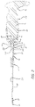
- FIG. 1 is perspective view of an adaptor or spacer assembled with a cannula attached to the adaptor, a drill extending through the adaptor and the cannula, and a driver attached to the drill;
- FIG. 2 is a cross-section of the assembly along Line 2 - 2 of FIG. 1 ;
- FIG. 3 is an exploded perspective view of the assembly of FIG. 1 ;
- FIG. 4 is a first enlarged perspective view of the adaptor from a first side thereof at a distal end thereof;
- FIG. 5 is a second enlarged perspective view of the adaptor from a second side thereof at the distal end thereof;
- FIG. 6 is a third enlarged perspective view of the adaptor from the second side thereof at a proximal end thereof;
- FIG. 7 is a first enlarged perspective view of a head portion of the cannula from a first side thereof at a proximal end thereof;
- FIG. 8 is a second enlarged perspective view of the head portion of the cannula from a second side thereof at the proximal end thereof;
- FIG. 9 is an exploded perspective view of the adaptor, the cannula, and a modified drill
- FIG. 10 is a side elevational view the adaptor, the cannula, and the modified drill assembled to one another;
- FIG. 11 is a cross-sectional view of the assembled adaptor, cannula, and modified drill taken along Line 11 - 11 of FIG. 10 ;
- FIG. 12 is a cross-sectional view of the assembled adaptor and modified drill taken along Line 12 - 12 of FIG. 10 .
- FIGS. 1-6 An adaptor or spacer according to one embodiment of the present invention is generally indicated by the numeral 10 in FIGS. 1-6 .
- the adaptor 10 is used in conjunction with a driver 12 , a drill 14 , and a cannula 16 .
- the adaptor 10 can be used to afford placement of the drill 14 and the cannula 16 into bone such as a vertebral body.
- the use of the drill 14 and the cannula 16 can afford access to the interior of the vertebral body.
- the adaptor 10 can serve to afford forward linear force applied to the driver 12 to be transferred through the adaptor 10 to the cannula 16 , and to prevent the drill 14 from extending more than a desired amount out of the cannula 16 . Additionally, the adaptor 10 can also serve to impart rotational movement of the drill 14 to the cannula 16 . As such, the adaptor 10 aids placement of the cannula 16 into bone.
- the adaptor 10 includes a proximal end 20 and a distal end 22 opposite from one another, and a mid-longitudinal axis extending the proximal end 20 and the distal end 22 .
- the adaptor 10 includes a end portion 24 , a body portion 26 , and a head portion 28 .
- the end portion 24 is provided at the proximal end 20
- the body portion 26 extends from the end portion 24 to the head portion 28
- the head portion 28 is provided at the distal end 22 .
- the end portion 24 is cylindrical
- the body portion 26 includes a middle portion 30 and first and second reinforcing struts 32 and 34 on opposite sides of the middle portion 30 .
- the head portion 28 includes a proximal surface 36 and a distal surface 38 opposite from one another, a first side surface 40 and a second side surface 42 opposite from one another, a first internal web portion 44 , a second internal web portion 46 , and a middle portion 48 .
- the adaptor 10 includes a passageway 50 for receiving a portion of the drill 14 extending therethrough.
- the passageway 50 extends through the end portion 24 , the middle portion 30 of the body portion 26 , and the middle portion 48 of the head portion 28 .
- the passageway 50 extends from a first opening 52 formed in the end portion 24 at the proximal end 20 of the adaptor 10 to a second opening 54 formed in the distal surface 38 of the head portion 28 at the distal end 22 of the adaptor 10 .
- the passageway 50 is configured to receive a portion of the drill 14 therethrough, and the passageway 50 is configured to receive a portion of the cannula 16 at the distal end 22 .
- the adaptor 10 is configured for releasably coupling to the cannula 16 .
- the adaptor 10 includes at least one coupler.
- the passageway 50 adjacent the second opening 54 can include a coupler such as threads 60
- the distal surface 38 can include a coupler such as a first tab 62 , a second tab 64 , and recesses 65 .
- the threads 60 , the first tab 62 , the second tab 64 , and one of the recesses 65 can facilitate releasable coupling with the cannula 16 .
- Such engagement can prevent movement of the adaptor 10 and the cannula 16 with respect to one another.
- a channel 66 can extend between the proximal end 20 and the distal end 22 of the adaptor 10 .
- the channel 66 provides access to the passageway 50 extending through the adaptor 10 .
- the driver 12 includes a handle portion 70 , a body portion 72 , and a chuck 74 .
- the chuck 74 includes detents 76 for facilitating engagement with the drill 14 .
- the handle portion 70 is rotatable relative to the body portion 72 , and rotation of the handle portion 70 by a user causes corresponding rotation of the chuck 74 .
- the user can manipulate the handle portion 70 to force the driver 12 forward linearly, and to cause rotation of the chuck 74 .
- such forward linear force and rotation of the chuck 74 is used to facilitate insertion of the drill 14 and the cannula 16 into the vertebral body.
- the drill 14 includes a proximal end 80 and a distal end 82 opposite from one another.
- the drill 14 includes a key portion 84 at the proximal end 80 , a collar portion 86 provided adjacent the key portion 84 , a shaft portion 88 extending from the key portion 84 through the collar portion 86 toward the distal end 82 .
- the shaft portion 88 includes a tip portion 90 at the distal end 82 including flutes facilitating removal of material from the bone.
- the key portion 84 can be received in and engaged to the chuck portion 74 of the driver 12 .
- the key portion 84 can include a recess 91 for receiving the detents 76 of the chuck 74 .
- the chuck portion 74 and the key portion 84 can be magnetized to secure the engagement therebetween. As such, rotation of the chuck portion 74 via manipulation of the handle portion 70 also rotates the drill 14 .
- the shaft portion 88 also includes various exterior markings 92 adjacent the collar portion 86 . During use of the drill 14 , as discussed below, the exterior markings 92 allow the user to determine the depth of the tip portion 90 in the bone.
- the cannula 16 includes a proximal end 100 and a distal end 102 opposite from one another.
- the cannula 16 includes a post portion 104 at the proximal end 100 , a handle portion 106 adjacent the post portion 104 , a pedestal portion 108 adjacent the handle portion 106 , and a shaft portion 110 extending from portions of the handle portion 106 and the pedestal portion 108 to the distal end 102 .
- the post portion 104 , the handle portion 106 , and the pedestal portion 108 can be unitarily formed with one another, and the shaft portion 110 can be secured within a passageway 112 extending through the post portion 104 , the handle portion 106 , and the pedestal portion 108 .
- the shaft portion 110 includes a passageway 114 therethrough.
- the passageway 114 together with the portion of the passageway 112 in which the shaft portion 110 is not received, form a passageway 116 extending from the proximal end 100 to the distal end 102 .
- the passageway 116 is configured to receive the shaft portion 88 of the drill 14 therethrough.
- the shaft portion 110 also includes various exterior markings 118 therealong. During use of the cannula 16 , as discussed below, the exterior markings 118 allow the user to determine the depth of the shaft portion 110 in the bone.
- the post portion 104 includes threads 120 configured to engage the threads 60 in the passageway 50 .
- the handle portion 106 includes a proximal surface 122 and a distal surface 124 opposite from one another.
- the proximal surface 122 includes a first recess 126 , a second recess 128 , and a detent 129 formed thereon.
- the first recess 126 is configured to receive and engage the first tab 62
- the second recess 128 is configured to receive and engage the second tab 64
- the detent 129 is configured for receipt in one of the recesses 65 .
- the first recess 126 comes into engagement with the first tab 62
- the second recess 128 comes into engagement with the second tab 64
- the detent 129 comes into engagement with one of the recesses 65 .
- the adaptor 10 is releasably coupled to the handle portion 106 of the cannula 16 .
- the adaptor 10 , the driver 12 , the drill 14 , and the cannula 16 can be assembled to one another as an assembly 130 . Thereafter, the user can manipulate the assembly 130 to insert the shaft portion 110 of the cannula 16 into the bone.
- the adaptor 10 can be engaged to the handle portion 106 of the cannula 16 to prevent movement of the adaptor 10 and the cannula 16 with respect to one another.
- the drill 14 can be engaged to the driver 12 by inserting the key portion 84 into the chuck portion 74 .
- the magnetic connection between the chuck portion 74 and the key portion 84 , and engagement between the detents 76 and the recess 91 serve to secure the driver 12 and the drill 14 to one another.
- the user can manipulate the driver 12 and the drill 14 to insert the shaft portion 88 of the drill 14 into the passageway 50 through the adaptor 10 and the passageway 116 through the cannula 16 .
- the shaft portion 88 of the drill 14 can be used to reinforce the shaft portion 110 of the cannula 16 .
- the lengths of the shaft portion 88 of the drill 14 and the shaft portion 110 of the cannula 16 can be selected to adjust the amount that the tip portion 90 extends out of the shaft portion 110 at the distal end 102 of the cannula 16 .
- the adaptor 10 can also be sized to prevent over-insertion of the tip portion 90 into the bone.
- the end portion 24 of the adaptor 10 is received at least partially within and engages the collar portion 86 of the drill 14 .
- the end portion 24 includes an exterior surface 140 and an end surface 142 .
- the collar portion 86 includes a recess 144 , and as depicted in FIG. 2 , the recess 144 includes an interior surface 146 and an end surface 148 .
- the end surface 142 and the end surface 148 can be engaged with one another, and the exterior surface 140 and the interior surface 146 can be cylindrical to allow the drill 14 to rotate relative to the adaptor 10 without interference.
- Forward linear force applied to the driver 12 is transferred to the drill 14 , and engagement of the end surface 142 and the end surface 148 with one another also affords such forward linear force applied to the driver 12 to be transferred through the adaptor 10 to the cannula 16 . That is, using the adaptor 10 , the user can push on the driver 12 and such pushing force can ultimately be transferred to both the drill 14 and the cannula 16 .
- the exterior surface 140 and the interior surface 146 are sized to allow the drill 14 to rotate relative to the adaptor 10 without interference. However, the friction due to contact between the end surface 142 and the end surface 148 can cause the adaptor 10 (and the cannula 16 attached thereto) to rotate with the drill 14 .
- simultaneous rotation of the cannula 16 with the drill 14 during linear advancement can aid the penetration of the shaft portion 110 of the cannula 16 into the bone.
- a modified drill 14 ′ can include a key 200 for receipt in the channel 66 adjacent the proximal end 20 of the adaptor 10 .
- the modified drill 14 ′ can be used with both the adaptor 10 and the cannula 16 . Furthermore, the modified drill 14 ′ can be used in place of the drill 12 in the assembly 130 . As discussed below, the interaction of the key 200 in the channel 66 causes the adaptor 10 (and the cannula 16 attached thereto) to rotate with the modified drill 14 ′. In other words, the adaptor 10 is rotatably coupled to the modified drill 14 ′ using the interaction of the key 200 in the channel 66 . The simultaneous rotation of the cannula 16 with the modified drill 14 ′ due to the interaction of the key 200 in the channel 66 can aid the penetration of the shaft portion 110 of the cannula 16 into the bone.
- the modified drill 14 ′ can include the components of the drill 14 .
- the modified drill 14 ′ like the drill 14 , includes a proximal end 80 and a distal end 82 opposite from one another, a key portion 84 at the proximal end 80 , and a shaft portion 88 extending from the key portion 84 toward the distal end 82 .
- the modified drill 14 ′ as depicted in FIGS. 9, 11, and 12 , includes a collar portion 202 that incorporates the key 200 .
- the collar portion 202 can be similar to the collar portion 86 of the drill 14 , except that the key 200 is incorporated into the collar portion 202 .
- the collar portion 202 includes a recess 204 , and the recess 204 includes an interior surface 206 and an end surface 208 .
- the key 200 can extend into the recess 204 , and interrupts both of the interior surface 206 and the end surface 208 .
- the key 200 as depicted in FIG. 12 , can also contact the shaft 88 .
- the end portion 24 of the adaptor 10 is received at least partially within the recess 204 and engages the collar portion 202 .
- the key 200 is at least partially received in the channel 66 .
- the key 200 can be sized to be received in the channel 66 with limited (if any) play to facilitate rotation of the adaptor 10 (and the cannula 16 attached thereto) with the modified drill 14 ′.
- Play between the adaptor 10 and the modified drill 14 ′ at the interface of the key 200 with the channel 66 can be limited by using resilient and non-resilient materials for the adaptor 10 and the modified drill 14 ′.
- the adaptor 10 can be made from a polymeric material or materials
- the modified drill 14 ′ can be made from a metallic material or materials.
- the key 200 can be metallic and portions of the end portion 24 adjacent the channel 66 can be polymeric.
- the channel 66 and the key 200 can be sized such that end portion 24 deflects slightly upon receipt of the key 200 in the channel 66 .
- the adaptor 10 instead could include an aperture (not shown) formed in the end portion 24 sized to receive the key 200 .
- the adaptor 10 instead could include the key 200
- the modified drill 14 ′ instead could include a channel (not shown) or an aperture (not shown) formed in the collar portion 202 for receiving the key 200 including on the adaptor 10 .
- the interaction of the key 200 in the channel 66 causes the simultaneous rotation of the adaptor 10 and the cannula 16 with the modified drill 14 ′.
- rotation of the cannula 16 with the modified drill 14 ′ can aid the penetration of the shaft portion 110 of the cannula 16 into the bone.
- the tip portion 90 When using the assembly 130 , the tip portion 90 is first contacted to the bone. Rotation of the drill 14 /modified drill 14 ′ via use of the driver 12 causes the tip portion 90 to penetrate the bone. In doing so, the tip portion 90 forms an aperture in the bone. Furthermore, linear force applied to the driver 12 is transferred to the drill 14 /modified drill 14 ′ and the cannula 16 . Such linear force can aid penetration of the tip portion 90 and the shaft portion 110 of the cannula 16 into the bone. Furthermore, rotation of the cannula 16 with the drill 14 /modified drill 14 ′ can aid penetration of the shaft portion 110 into the bone. The exterior markings 118 on the shaft portion 110 can be used to afford insertion of the shaft portion 110 to a proper depth in the bone.
- the drill 14 /modified drill 14 ′ can be removed from the passageway 50 and the passageway 116 , and the adaptor 10 can be disconnected from the cannula 16 . Thereafter, the drill 14 /modified drill 14 ′ or another instrument can be reinserted into the passageway 116 .
- the drill 14 /modified drill 14 ′ can be used to further enlarge the aperture formed in the bone. If using the drill 14 /modified drill 14 ′ without the adaptor 10 , the markings 92 on the shaft portion 88 of the drill 14 /modified drill 14 ′ can be used to afford insertion of the shaft portion 88 to a proper depth in the bone.
- another instrument such as an ablation probe
- the handle portion 106 of the cannula 16 can be manipulated by the user to facilitate insertion thereof into the bone.
- the user can manipulate the handle portion 106 to insert the shaft portion 110 into the bone, and the exterior markings 118 on the shaft portion 110 can be used to afford insertion of the shaft portion 110 to a proper depth in the bone.
- the adaptor 10 can then be engaged to the handle portion 106 of the cannula 16 to prevent movement of the adaptor 10 and the cannula 16 with respect to one another. Thereafter, the shaft portion 88 of the drill 14 /modified drill 14 ′ can be inserted through the passageway 50 and the passageway 116 .
- the drill 14 /modified drill 14 ′ can be attached to or detached from the driver 12 during initial insertion thereof into the passageway 50 and the passageway 116 .
- the driver 12 can then be used to rotate the drill 14 /modified drill 14 ′ to cause the tip portion 90 to penetrate the bone.
Landscapes
- Health & Medical Sciences (AREA)
- Surgery (AREA)
- Life Sciences & Earth Sciences (AREA)
- Biomedical Technology (AREA)
- Medical Informatics (AREA)
- Orthopedic Medicine & Surgery (AREA)
- Oral & Maxillofacial Surgery (AREA)
- Engineering & Computer Science (AREA)
- Dentistry (AREA)
- Heart & Thoracic Surgery (AREA)
- Nuclear Medicine, Radiotherapy & Molecular Imaging (AREA)
- Molecular Biology (AREA)
- Animal Behavior & Ethology (AREA)
- General Health & Medical Sciences (AREA)
- Public Health (AREA)
- Veterinary Medicine (AREA)
- Surgical Instruments (AREA)
Abstract
Description
Claims (19)
Priority Applications (2)
| Application Number | Priority Date | Filing Date | Title |
|---|---|---|---|
| US16/250,306 US11304709B2 (en) | 2018-01-25 | 2019-01-17 | Adaptor and drill for use with a driver and a cannula for drilling into bone |
| PCT/US2020/013630 WO2020150314A1 (en) | 2019-01-17 | 2020-01-15 | Adaptor and drill for use with a driver and a cannula for drilling into bone |
Applications Claiming Priority (2)
| Application Number | Priority Date | Filing Date | Title |
|---|---|---|---|
| US15/880,088 US10980587B2 (en) | 2018-01-25 | 2018-01-25 | Adaptor for use with a driver, a drill, and a cannula for drilling into bone |
| US16/250,306 US11304709B2 (en) | 2018-01-25 | 2019-01-17 | Adaptor and drill for use with a driver and a cannula for drilling into bone |
Related Parent Applications (1)
| Application Number | Title | Priority Date | Filing Date |
|---|---|---|---|
| US15/880,088 Continuation-In-Part US10980587B2 (en) | 2018-01-25 | 2018-01-25 | Adaptor for use with a driver, a drill, and a cannula for drilling into bone |
Publications (2)
| Publication Number | Publication Date |
|---|---|
| US20190223890A1 US20190223890A1 (en) | 2019-07-25 |
| US11304709B2 true US11304709B2 (en) | 2022-04-19 |
Family
ID=67299114
Family Applications (1)
| Application Number | Title | Priority Date | Filing Date |
|---|---|---|---|
| US16/250,306 Active 2039-02-28 US11304709B2 (en) | 2018-01-25 | 2019-01-17 | Adaptor and drill for use with a driver and a cannula for drilling into bone |
Country Status (1)
| Country | Link |
|---|---|
| US (1) | US11304709B2 (en) |
Families Citing this family (1)
| Publication number | Priority date | Publication date | Assignee | Title |
|---|---|---|---|---|
| US12465396B2 (en) * | 2021-04-14 | 2025-11-11 | Eminent Spine Llc | Minimally invasive spinal instrument and method for use of same |
Citations (43)
| Publication number | Priority date | Publication date | Assignee | Title |
|---|---|---|---|---|
| FR2344267A1 (en) | 1976-03-16 | 1977-10-14 | Ulrich Max | PERFORATION DEVICE FOR BONE SURGERY |
| US4265231A (en) | 1979-04-30 | 1981-05-05 | Scheller Jr Arnold D | Curved drill attachment for bone drilling uses |
| US4549538A (en) | 1982-11-12 | 1985-10-29 | Zimmer, Inc. | Pin inserter sheath |
| US5113571A (en) | 1990-01-29 | 1992-05-19 | Manska Wayne E | Method of manufacturing a connector for medical devices |
| US5120312A (en) | 1990-04-20 | 1992-06-09 | Regents Of The University Of Minnesota | Method and apparatus for catheterization |
| US5449370A (en) * | 1993-05-12 | 1995-09-12 | Ethicon, Inc. | Blunt tipped ultrasonic trocar |
| US5575794A (en) | 1993-02-12 | 1996-11-19 | Walus; Richard L. | Tool for implanting a fiducial marker |
| WO1999012481A1 (en) | 1997-09-10 | 1999-03-18 | United States Surgical Corporation | Method and instrumentation for implant insertion |
| CN2340380Y (en) | 1998-10-19 | 1999-09-29 | 阚士峰 | Medical canula style needle for trephination |
| US6575919B1 (en) * | 1999-10-19 | 2003-06-10 | Kyphon Inc. | Hand-held instruments that access interior body regions |
| EP1374784A1 (en) | 2002-06-18 | 2004-01-02 | Stryker Spine | Variable depth bone drill guide |
| US20040215102A1 (en) | 2001-08-09 | 2004-10-28 | Susumu Ikehara | Marrow fluid sampling set and marrow needle |
| WO2008011262A2 (en) | 2006-07-21 | 2008-01-24 | Bassem Georgy | Device and method for introducing flowable material into a body cavity |
| US7699850B2 (en) | 2002-05-31 | 2010-04-20 | Vidacare Corporation | Apparatus and method to access bone marrow |
| US20100145142A1 (en) | 2008-10-07 | 2010-06-10 | Neurendo B.V. | Minimal invasive neurosurgery assembly as well as a method for neurosurgery using such a neurosurgery assembly |
| US7850620B2 (en) | 2002-05-31 | 2010-12-14 | Vidacare Corporation | Biopsy devices and related methods |
| US20110245833A1 (en) | 2010-03-31 | 2011-10-06 | Wayne Anderson | Depth controllable and measurable medical driver devices and methods of use |
| US20120053588A1 (en) | 2010-08-31 | 2012-03-01 | Lozier Antony J | Drill bit for osteochondral drilling with guiding element and uses thereof |
| US20120232658A1 (en) | 2011-03-10 | 2012-09-13 | Interventional Spine, Inc. | Method and apparatus for minimally invasive insertion of intervertebral implants |
| US20130041345A1 (en) | 2011-07-11 | 2013-02-14 | Christopher Brian Kilcoin | Sternal locators and associated systems and methods |
| US8414585B2 (en) | 2007-02-13 | 2013-04-09 | Arthroplasty Innovations, Llc | Flexible trephine and method of removing a bowed implant from a bone |
| WO2013179013A1 (en) | 2012-06-01 | 2013-12-05 | Depuy (Ireland) | Surgical instruments |
| WO2015006296A1 (en) | 2013-07-09 | 2015-01-15 | Stryker Corporation | Surgical drill having brake that, upon the drill bit penetrating through bone, prevents further insertion of the drill bit |
| US8944069B2 (en) | 2006-09-12 | 2015-02-03 | Vidacare Corporation | Assemblies for coupling intraosseous (IO) devices to powered drivers |
| US8998848B2 (en) | 2004-11-12 | 2015-04-07 | Vidacare LLC | Intraosseous device and methods for accessing bone marrow in the sternum and other target areas |
| US20150230823A1 (en) | 2014-02-17 | 2015-08-20 | Vidacare LLC | Powered driver actuated by force on driveshaft and related kits, components, and methods |
| US9192759B2 (en) | 2014-03-31 | 2015-11-24 | Dennison Hamilton | System and method for stabilizing implanted spinal cord stimulators |
| US20160022282A1 (en) | 2013-03-15 | 2016-01-28 | Larry J. Miller | Intraosseous device handles, systems, and methods |
| US9339294B2 (en) | 2012-09-07 | 2016-05-17 | Zimmer Knee Creations, Inc. | Instruments for controlled delivery of injectable materials into bone |
| US20160228131A1 (en) | 2013-10-15 | 2016-08-11 | Stryker Corporation | Device for creating a void space in a living tissue, the device including a handle with a control knob that can be set regardless of the orientation of the handle |
| US9433400B2 (en) | 2004-01-26 | 2016-09-06 | Vidacare LLC | Manual intraosseous device |
| US9504477B2 (en) * | 2003-05-30 | 2016-11-29 | Vidacare LLC | Powered driver |
| US9510910B2 (en) | 2006-09-12 | 2016-12-06 | Vidacare LLC | Medical procedures trays and related methods |
| DE202016107414U1 (en) | 2016-12-28 | 2017-01-16 | Rz Medizintechnik Gmbh | stop sleeve |
| US20170049460A1 (en) | 2012-11-14 | 2017-02-23 | British Columbia Cancer Agency Branch | Cannulated hammer drill attachment |
| WO2017074507A1 (en) | 2015-10-26 | 2017-05-04 | Nuscale Power, Llc | Passive cooling to cold shutdown |
| US9687255B2 (en) | 2008-06-17 | 2017-06-27 | Globus Medical, Inc. | Device and methods for fracture reduction |
| US9757135B1 (en) | 2013-06-14 | 2017-09-12 | Scott Kelley | Trephine reamer for use in removal of a femoral component of a hip replacement implant |
| US9839425B2 (en) | 2014-06-26 | 2017-12-12 | Covidien Lp | Adapter assembly for interconnecting electromechanical surgical devices and surgical loading units, and surgical systems thereof |
| US9844362B2 (en) | 2015-01-13 | 2017-12-19 | Covidien Lp | Exchangeable core biopsy needle |
| US9883853B2 (en) | 2013-03-15 | 2018-02-06 | Teleflex Medical Devices S.À.R.L. | Intraosseous device couplers, drivers, kits, and methods |
| US10004504B2 (en) | 2010-11-02 | 2018-06-26 | Covidien Lp | Adapter for powered surgical devices |
| EP3517059A1 (en) | 2018-01-25 | 2019-07-31 | Medtronic Holding Company Sàrl | Adaptor for use with a driver, a drill, and a cannula for drilling into bone |
-
2019
- 2019-01-17 US US16/250,306 patent/US11304709B2/en active Active
Patent Citations (46)
| Publication number | Priority date | Publication date | Assignee | Title |
|---|---|---|---|---|
| FR2344267A1 (en) | 1976-03-16 | 1977-10-14 | Ulrich Max | PERFORATION DEVICE FOR BONE SURGERY |
| US4265231A (en) | 1979-04-30 | 1981-05-05 | Scheller Jr Arnold D | Curved drill attachment for bone drilling uses |
| US4549538A (en) | 1982-11-12 | 1985-10-29 | Zimmer, Inc. | Pin inserter sheath |
| US5113571A (en) | 1990-01-29 | 1992-05-19 | Manska Wayne E | Method of manufacturing a connector for medical devices |
| US5120312A (en) | 1990-04-20 | 1992-06-09 | Regents Of The University Of Minnesota | Method and apparatus for catheterization |
| US5575794A (en) | 1993-02-12 | 1996-11-19 | Walus; Richard L. | Tool for implanting a fiducial marker |
| US5449370A (en) * | 1993-05-12 | 1995-09-12 | Ethicon, Inc. | Blunt tipped ultrasonic trocar |
| WO1999012481A1 (en) | 1997-09-10 | 1999-03-18 | United States Surgical Corporation | Method and instrumentation for implant insertion |
| CN2340380Y (en) | 1998-10-19 | 1999-09-29 | 阚士峰 | Medical canula style needle for trephination |
| US6575919B1 (en) * | 1999-10-19 | 2003-06-10 | Kyphon Inc. | Hand-held instruments that access interior body regions |
| US20040215102A1 (en) | 2001-08-09 | 2004-10-28 | Susumu Ikehara | Marrow fluid sampling set and marrow needle |
| US7699850B2 (en) | 2002-05-31 | 2010-04-20 | Vidacare Corporation | Apparatus and method to access bone marrow |
| US9717564B2 (en) | 2002-05-31 | 2017-08-01 | Teleflex Medical Devices S.À R.L. | Biopsy devices and related methods |
| US7850620B2 (en) | 2002-05-31 | 2010-12-14 | Vidacare Corporation | Biopsy devices and related methods |
| EP1374784A1 (en) | 2002-06-18 | 2004-01-02 | Stryker Spine | Variable depth bone drill guide |
| US9504477B2 (en) * | 2003-05-30 | 2016-11-29 | Vidacare LLC | Powered driver |
| US9433400B2 (en) | 2004-01-26 | 2016-09-06 | Vidacare LLC | Manual intraosseous device |
| US8998848B2 (en) | 2004-11-12 | 2015-04-07 | Vidacare LLC | Intraosseous device and methods for accessing bone marrow in the sternum and other target areas |
| WO2008011262A2 (en) | 2006-07-21 | 2008-01-24 | Bassem Georgy | Device and method for introducing flowable material into a body cavity |
| US9510910B2 (en) | 2006-09-12 | 2016-12-06 | Vidacare LLC | Medical procedures trays and related methods |
| US8944069B2 (en) | 2006-09-12 | 2015-02-03 | Vidacare Corporation | Assemblies for coupling intraosseous (IO) devices to powered drivers |
| US8414585B2 (en) | 2007-02-13 | 2013-04-09 | Arthroplasty Innovations, Llc | Flexible trephine and method of removing a bowed implant from a bone |
| US9687255B2 (en) | 2008-06-17 | 2017-06-27 | Globus Medical, Inc. | Device and methods for fracture reduction |
| US20100145142A1 (en) | 2008-10-07 | 2010-06-10 | Neurendo B.V. | Minimal invasive neurosurgery assembly as well as a method for neurosurgery using such a neurosurgery assembly |
| US20110245833A1 (en) | 2010-03-31 | 2011-10-06 | Wayne Anderson | Depth controllable and measurable medical driver devices and methods of use |
| US20120053588A1 (en) | 2010-08-31 | 2012-03-01 | Lozier Antony J | Drill bit for osteochondral drilling with guiding element and uses thereof |
| US10004504B2 (en) | 2010-11-02 | 2018-06-26 | Covidien Lp | Adapter for powered surgical devices |
| US20120232658A1 (en) | 2011-03-10 | 2012-09-13 | Interventional Spine, Inc. | Method and apparatus for minimally invasive insertion of intervertebral implants |
| US20130041345A1 (en) | 2011-07-11 | 2013-02-14 | Christopher Brian Kilcoin | Sternal locators and associated systems and methods |
| WO2013179013A1 (en) | 2012-06-01 | 2013-12-05 | Depuy (Ireland) | Surgical instruments |
| US9339294B2 (en) | 2012-09-07 | 2016-05-17 | Zimmer Knee Creations, Inc. | Instruments for controlled delivery of injectable materials into bone |
| US20170049460A1 (en) | 2012-11-14 | 2017-02-23 | British Columbia Cancer Agency Branch | Cannulated hammer drill attachment |
| US9883853B2 (en) | 2013-03-15 | 2018-02-06 | Teleflex Medical Devices S.À.R.L. | Intraosseous device couplers, drivers, kits, and methods |
| US20160022282A1 (en) | 2013-03-15 | 2016-01-28 | Larry J. Miller | Intraosseous device handles, systems, and methods |
| US9757135B1 (en) | 2013-06-14 | 2017-09-12 | Scott Kelley | Trephine reamer for use in removal of a femoral component of a hip replacement implant |
| US20160120553A1 (en) | 2013-07-09 | 2016-05-05 | Jenny Xie | Surgical drill having a brake that, upon the drill bit penetrating through bone, prevents further insertion of the drill |
| WO2015006296A1 (en) | 2013-07-09 | 2015-01-15 | Stryker Corporation | Surgical drill having brake that, upon the drill bit penetrating through bone, prevents further insertion of the drill bit |
| US20160228131A1 (en) | 2013-10-15 | 2016-08-11 | Stryker Corporation | Device for creating a void space in a living tissue, the device including a handle with a control knob that can be set regardless of the orientation of the handle |
| US20150230823A1 (en) | 2014-02-17 | 2015-08-20 | Vidacare LLC | Powered driver actuated by force on driveshaft and related kits, components, and methods |
| US9192759B2 (en) | 2014-03-31 | 2015-11-24 | Dennison Hamilton | System and method for stabilizing implanted spinal cord stimulators |
| US9839425B2 (en) | 2014-06-26 | 2017-12-12 | Covidien Lp | Adapter assembly for interconnecting electromechanical surgical devices and surgical loading units, and surgical systems thereof |
| US9844362B2 (en) | 2015-01-13 | 2017-12-19 | Covidien Lp | Exchangeable core biopsy needle |
| WO2017074507A1 (en) | 2015-10-26 | 2017-05-04 | Nuscale Power, Llc | Passive cooling to cold shutdown |
| DE202016107414U1 (en) | 2016-12-28 | 2017-01-16 | Rz Medizintechnik Gmbh | stop sleeve |
| EP3517059A1 (en) | 2018-01-25 | 2019-07-31 | Medtronic Holding Company Sàrl | Adaptor for use with a driver, a drill, and a cannula for drilling into bone |
| US10980587B2 (en) * | 2018-01-25 | 2021-04-20 | Medtronic Holding Company Sàrl | Adaptor for use with a driver, a drill, and a cannula for drilling into bone |
Non-Patent Citations (4)
| Title |
|---|
| European Search Report dated Jun. 18, 2019 from European Application No. 19150203.8. |
| International Search Report and Written Opinion issued Apr. 6, 2020 for International Application No. PCT/US2020/013630. |
| Marcus Holmberg, PhD; Minimally Invasive Ponto Surgery—A new Perspective On Bone Anchored Surgery, Bone Conduction & Middle Ear; AudiologyOnline, Jul. 1, 2017; 10 pages. |
| Office Action dated May 4, 2020 from corresponding European Application No. 19150203.8. |
Also Published As
| Publication number | Publication date |
|---|---|
| US20190223890A1 (en) | 2019-07-25 |
Similar Documents
| Publication | Publication Date | Title |
|---|---|---|
| US10980587B2 (en) | Adaptor for use with a driver, a drill, and a cannula for drilling into bone | |
| US8398685B2 (en) | Transbuccal plate holding cannula | |
| US6524238B2 (en) | Universal handle and method for use | |
| US7001333B2 (en) | Surgical retractor system | |
| US5354299A (en) | Method of revising a screw in a tunnel | |
| US9763675B2 (en) | Angled instrument assembly | |
| EP1386587B1 (en) | Surgical instrument with rotary cutting member | |
| CN1893881B (en) | surgical drill guide | |
| US10653444B2 (en) | Perforating trocar | |
| HK1048751A1 (en) | Coupling device for instrument parts | |
| US20110099752A1 (en) | Releasably interlocking instrument handle and method for use thereof | |
| US11304709B2 (en) | Adaptor and drill for use with a driver and a cannula for drilling into bone | |
| US10987196B2 (en) | Drill guide | |
| US7992878B2 (en) | Helical lead for a drive shaft collet | |
| WO2020150314A1 (en) | Adaptor and drill for use with a driver and a cannula for drilling into bone | |
| US20080171984A1 (en) | Cannula driver and system | |
| US20220054225A1 (en) | Hand operated surgical instrument having an improved tool bit connector | |
| US20220061883A1 (en) | Locking Trocar Assembly | |
| WO2001078608A3 (en) | Bone marrow biopsy needle |
Legal Events
| Date | Code | Title | Description |
|---|---|---|---|
| FEPP | Fee payment procedure |
Free format text: ENTITY STATUS SET TO UNDISCOUNTED (ORIGINAL EVENT CODE: BIG.); ENTITY STATUS OF PATENT OWNER: LARGE ENTITY |
|
| AS | Assignment |
Owner name: MEDTRONIC HOLDINGS COMPANY SARL, SWITZERLAND Free format text: ASSIGNMENT OF ASSIGNORS INTEREST;ASSIGNORS:DRUMA, CALIN;NOLAN, TRAVIS J.;SASAKI, NEIL S.;SIGNING DATES FROM 20181002 TO 20190926;REEL/FRAME:050625/0011 |
|
| STPP | Information on status: patent application and granting procedure in general |
Free format text: NON FINAL ACTION MAILED |
|
| STPP | Information on status: patent application and granting procedure in general |
Free format text: RESPONSE TO NON-FINAL OFFICE ACTION ENTERED AND FORWARDED TO EXAMINER |
|
| STPP | Information on status: patent application and granting procedure in general |
Free format text: NOTICE OF ALLOWANCE MAILED -- APPLICATION RECEIVED IN OFFICE OF PUBLICATIONS |
|
| STPP | Information on status: patent application and granting procedure in general |
Free format text: PUBLICATIONS -- ISSUE FEE PAYMENT VERIFIED |
|
| STCF | Information on status: patent grant |
Free format text: PATENTED CASE |
|
| AS | Assignment |
Owner name: MEDTRONIC EUROPE SARL, SWITZERLAND Free format text: MERGER;ASSIGNOR:MEDTRONIC HOLDING COMPANY SARL;REEL/FRAME:070809/0661 Effective date: 20241018 |
|
| MAFP | Maintenance fee payment |
Free format text: PAYMENT OF MAINTENANCE FEE, 4TH YEAR, LARGE ENTITY (ORIGINAL EVENT CODE: M1551); ENTITY STATUS OF PATENT OWNER: LARGE ENTITY Year of fee payment: 4 |