US11300214B2 - Top entry ball valve - Google Patents
Top entry ball valve Download PDFInfo
- Publication number
- US11300214B2 US11300214B2 US15/479,936 US201715479936A US11300214B2 US 11300214 B2 US11300214 B2 US 11300214B2 US 201715479936 A US201715479936 A US 201715479936A US 11300214 B2 US11300214 B2 US 11300214B2
- Authority
- US
- United States
- Prior art keywords
- axis
- valve element
- gear assembly
- seat assemblies
- ball valve
- Prior art date
- Legal status (The legal status is an assumption and is not a legal conclusion. Google has not performed a legal analysis and makes no representation as to the accuracy of the status listed.)
- Active, expires
Links
Images


Classifications
-
- F—MECHANICAL ENGINEERING; LIGHTING; HEATING; WEAPONS; BLASTING
- F16—ENGINEERING ELEMENTS AND UNITS; GENERAL MEASURES FOR PRODUCING AND MAINTAINING EFFECTIVE FUNCTIONING OF MACHINES OR INSTALLATIONS; THERMAL INSULATION IN GENERAL
- F16K—VALVES; TAPS; COCKS; ACTUATING-FLOATS; DEVICES FOR VENTING OR AERATING
- F16K5/00—Plug valves; Taps or cocks comprising only cut-off apparatus having at least one of the sealing faces shaped as a more or less complete surface of a solid of revolution, the opening and closing movement being predominantly rotary
- F16K5/08—Details
- F16K5/14—Special arrangements for separating the sealing faces or for pressing them together
- F16K5/20—Special arrangements for separating the sealing faces or for pressing them together for plugs with spherical surfaces
- F16K5/201—Special arrangements for separating the sealing faces or for pressing them together for plugs with spherical surfaces with the housing or parts of the housing mechanically pressing the seal against the plug
-
- F—MECHANICAL ENGINEERING; LIGHTING; HEATING; WEAPONS; BLASTING
- F16—ENGINEERING ELEMENTS AND UNITS; GENERAL MEASURES FOR PRODUCING AND MAINTAINING EFFECTIVE FUNCTIONING OF MACHINES OR INSTALLATIONS; THERMAL INSULATION IN GENERAL
- F16K—VALVES; TAPS; COCKS; ACTUATING-FLOATS; DEVICES FOR VENTING OR AERATING
- F16K25/00—Details relating to contact between valve members and seats
-
- F—MECHANICAL ENGINEERING; LIGHTING; HEATING; WEAPONS; BLASTING
- F16—ENGINEERING ELEMENTS AND UNITS; GENERAL MEASURES FOR PRODUCING AND MAINTAINING EFFECTIVE FUNCTIONING OF MACHINES OR INSTALLATIONS; THERMAL INSULATION IN GENERAL
- F16K—VALVES; TAPS; COCKS; ACTUATING-FLOATS; DEVICES FOR VENTING OR AERATING
- F16K5/00—Plug valves; Taps or cocks comprising only cut-off apparatus having at least one of the sealing faces shaped as a more or less complete surface of a solid of revolution, the opening and closing movement being predominantly rotary
- F16K5/06—Plug valves; Taps or cocks comprising only cut-off apparatus having at least one of the sealing faces shaped as a more or less complete surface of a solid of revolution, the opening and closing movement being predominantly rotary with plugs having spherical surfaces; Packings therefor
- F16K5/0626—Easy mounting or dismounting means
- F16K5/0636—Easy mounting or dismounting means the spherical plug being insertable from the top of the housing
Definitions
- the present invention relates a top entry ball valve for controlling the flow of a fluid through a pipe, and a method of assembling such a valve.
- Ball valves typically comprise of a spherical ball-shaped valve element, with a through bore extending therethrough.
- the valve element is rotatably mounted in a housing which has aligned openings on either side, one for entry of fluid into the housing and one for exit of fluid from the housing.
- the valve element may be rotated such that the bore may either be aligned in the same direction as the openings or perpendicular to the openings. In the perpendicular orientation flow through the valve is prevented, while in the parallel direction flow of fluid through the valve is allowed.
- Each of the openings of the housing is provided with a sealing seat assembly for sealing between the opening and the ball valve element.
- both of the seat assemblies In order to assemble such a ball valve, both of the seat assemblies must be retracted while the ball valve element is inserted into the housing. Once the ball valve element has been inserted into the housing, the seat assemblies are returned to seal with the element.
- the present application provides a top entry ball valve according to claim 1 , and a method of assembling a top entry ball valve according to claim 7 .
- FIG. 1 is a partially cutaway view of a top entry ball valve according to one embodiment of the present invention
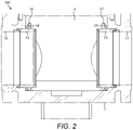
- FIG. 2 is a cross-sectional view on the line X-X of FIG. 1 , partway through assembly of the top entry ball valve with the valve element yet to be inserted;
- FIG. 3 is a cross-sectional view on the line X-X of FIG. 1 , partway through assembly of the top entry ball valve with the valve element inserted;
- FIG. 4 is a cross-sectional view on the line X-X of FIG. 1 of an assembled top entry ball valve
- FIG. 5 is a cross-sectional view on the line Y-Y of FIG. 1 of an assembled top entry ball valve
- FIG. 6 is a cross-sectional view on the line Z-Z of FIG. 1 of an assembled top entry ball valve
- FIG. 7 is an enlarged view of a part of FIG. 6 .
- FIGS. 1 to 7 An embodiment of the present invention is shown in the top entry ball valve 100 in FIGS. 1 to 7 .
- the housing 1 of the top entry ball valve 100 is provided with two axially aligned opening bores 10 , 11 for attaching in a fluid pipe system.
- the fluid to be controlled by the top entry ball valve 100 flows through the top entry ball valve 100 along the axis of these axially aligned opening bores 10 , 11 .
- the left opening 10 is considered the entry opening and the right opening 11 is considered the exit opening.
- the valve may operate in a reverse orientation.
- the housing 1 is provided with a central cavity 4 , and a top opening.
- the top opening is covered in use by a valve lid 2 which is attached to the housing 1 .
- the top entry ball valve 100 is provided with venting and drainage connections 24 , 25 , 26 and 27 as is standard practice in the field.
- a ball valve element 3 is mounted within the central cavity 4 in the housing 1 .
- the valve 100 is characterised as a top entry ball valve 100 as the ball valve element 3 is inserted into the central cavity 4 in a direction transverse to the direction of flow of fluid through the top entry ball valve 100 .
- This direction generally corresponds to the axis of the axially aligned opening bores 10 , 11 .
- the ball valve element 3 may be inserted in a direction perpendicular to the direction of flow of fluid through the top entry ball valve 100 .
- the ball valve element 3 is essentially spherically shaped and comprises a through bore 5 .
- the ball valve element 3 is able to rotate about an axis perpendicular to the axis of the opening bores 10 , 11 within the central cavity 4 , between a position wherein the bore 5 is axially aligned with the openings 10 , 11 as shown in FIG. 1 , and a position wherein the bore 5 is perpendicular with the openings 10 , 11 .
- Rotation of the ball valve element 3 is driven by a valve stem 7 which is attached to a top surface of the ball valve element 3 .
- fluid flows into the entry opening 10 , through the bore 5 of the ball valve element 3 and out of the exit opening 11 .
- fluid flowing into the entry opening 10 is not able to flow past the ball valve element 3 . In this manner a user may rotate the valve stem 7 to control opening and closing of the top entry ball valve 100 in order to control a fluid flow.
- Each opening bore 10 , 11 is provided with a movable seat assembly 12 , 13 .
- the seat assemblies 12 , 13 are annular and sit in and form a fluid seal with annular recesses in openings 10 , 11 respectively.
- the inner diameter of the seat assemblies 12 , 13 is substantially equal to the inner diameter of the openings 10 , 11 .
- Each seat assembly 12 , 13 is provided with a sealing surface generally facing the centre of the top entry ball valve 100 and that is shaped to seal against an outer surface of the ball valve element 3 .
- the seat assemblies 12 , 13 engage with an inner surface of each opening bore 10 , 11 and with an outer surface of the ball valve element 3 to form a liquid tight seal.
- the seat assemblies 12 , 13 are movable in an axial direction along the axis of the openings 10 , 11 as described below.
- each seat assembly 12 , 13 Attached to the outer surface of each seat assembly 12 , 13 is a geared lock ring 14 , 15 .
- the geared lock rings 14 , 15 are free to rotate within the housing 1 , but are prevented from moving axially.
- the outer surface of the seat assemblies 12 , 13 have a threaded connection with the inner surface of the geared lock rings 14 , 15 .
- the geared lock rings 14 , 15 are provided with gear teeth on their outer diameter as best depicted in FIG. 7 .
- a pair of threaded worm drives 16 , 17 is provided within the housing 1 and each engages with the teeth of one of the geared lock rings 14 , 15 .
- each worm drive 16 , 17 is rotatably mounted within the housing 1 , while the opposite end 18 , 19 of the worm drive 16 , 17 extends outside the housing 1 such that a user is able to rotate the threaded worm drives 16 , 17 .
- Rotation of the threaded worm drives 16 , 17 will drive either a clockwise or anticlockwise movement of the geared lock rings 14 , 15 .
- the rotation of the geared lock rings 14 , 15 is transferred via the threaded engagement to the seat assemblies 12 , 13 in order to axially move the seat assemblies 12 , 13 . This movement is either towards or away from the centre of the housing 1 depending upon the direction of rotation of the threaded worm drives 16 , 17 .
- top entry ball valve 100 The assembly of a top entry ball valve 100 according to the present invention will now be described with reference to FIGS. 2, 3 and 4 .
- FIG. 2 depicts a partially assembled top entry ball valve 100 .
- the ball valve element 3 is yet to be inserted into the central cavity 4 of the housing 1 .
- the threaded worm drives 16 , 17 have been fully rotated to cause the geared lock rings 14 , 15 to move the seat assemblies 12 , 13 away from the centre of the housing 1 .
- the ball valve element 3 is then inserted into the central cavity 4 in a direction transverse to the axis of the axially aligned opening bores 10 , 11 as shown in FIG. 3 .
- the retraction of the seat assemblies 12 , 13 allows the ball valve element 3 to be easily inserted into the central cavity 4 .
- the seat assemblies 12 , 13 may be moved axially back towards the centre of the housing 1 as shown in FIG. 4 .
- the threaded worm drives 16 , 17 are rotated by the user in the opposite direction, causing the geared lock rings 14 , 15 to rotate and, via their threaded connection with the seat assemblies 12 , 13 , causing the seat assemblies 12 , 13 to move axially inwards towards the ball valve element 3 until they are in a sealing contact. While in the present embodiment the threaded worm drives 16 , 17 are shown without any interconnecting members, embodiments are also envisioned wherein the threaded worm drives 16 , 17 are connected to rotate at the same rate.
- the ball valve lid 2 is then attached to the housing 1 and the top entry ball valve 100 installation is complete.
- FIG. 5 depicts a top cutaway view of the top entry ball valve 100 in a fully installed configuration. Bores 22 , 23 are provided in the housing 1 , in which the threaded worm drives 16 , 17 are rotatably mounted. FIGS. 6 and 7 show a side cross sectional view of the top entry ball valve 100 .
- This top entry ball valve 100 and method of assembly thereof greatly simplifies the valve 100 assembly and disassembly. No special tools are required and as such a single operator may install or uninstall the valve 100 without any additional specialised training, by rotation of the threaded worm drives 16 , 17 .
- the simplified assembly also requires fewer access points and as such fewer potential leak paths.
- the seat assemblies 12 , 13 can still be retracted slightly, allowing fluid to flow past the ball valve element 3 in order to flush away any debris which is jamming the top entry ball valve 100 .
- the threaded worm drives 16 , 17 can be further rotated to maintain a fluid seal between the seat assemblies and the ball valve element 3 , thereby extending the useful life of the valve 100 .
Landscapes
- Engineering & Computer Science (AREA)
- General Engineering & Computer Science (AREA)
- Mechanical Engineering (AREA)
- Taps Or Cocks (AREA)
Abstract
Description
Claims (6)
Applications Claiming Priority (3)
| Application Number | Priority Date | Filing Date | Title |
|---|---|---|---|
| GB1606798.5A GB2549497B (en) | 2016-04-19 | 2016-04-19 | Top entry ball valve |
| GB1606798.5 | 2016-04-19 | ||
| GB1606798 | 2016-04-19 |
Publications (2)
| Publication Number | Publication Date |
|---|---|
| US20170299072A1 US20170299072A1 (en) | 2017-10-19 |
| US11300214B2 true US11300214B2 (en) | 2022-04-12 |
Family
ID=59958344
Family Applications (1)
| Application Number | Title | Priority Date | Filing Date |
|---|---|---|---|
| US15/479,936 Active 2039-03-06 US11300214B2 (en) | 2016-04-19 | 2017-04-05 | Top entry ball valve |
Country Status (2)
| Country | Link |
|---|---|
| US (1) | US11300214B2 (en) |
| GB (1) | GB2549497B (en) |
Families Citing this family (3)
| Publication number | Priority date | Publication date | Assignee | Title |
|---|---|---|---|---|
| CN205877247U (en) * | 2016-05-26 | 2017-01-11 | 刘晓琦 | Forced sealing ball valve |
| US10544868B2 (en) * | 2018-02-14 | 2020-01-28 | Fisher Controls International Llc | Ball valve having an adjustable trim arrangement |
| US11384846B2 (en) * | 2020-02-20 | 2022-07-12 | Worldwide Oilfield Machine, Inc. | Top entry ball valve and method |
Citations (6)
| Publication number | Priority date | Publication date | Assignee | Title |
|---|---|---|---|---|
| US3187776A (en) * | 1963-02-27 | 1965-06-08 | Keystone Valve Corp | Flow control pipeline fitting |
| US3653631A (en) | 1969-10-23 | 1972-04-04 | Gordon F Hurst | Ball valve construction |
| US3934606A (en) * | 1974-06-20 | 1976-01-27 | Grove Valve And Regulator Company | Cam locked ball valve |
| GB2143305A (en) | 1983-06-16 | 1985-02-06 | Werner Hartmann | Sealing arrangement for a valve member |
| US4727901A (en) * | 1986-03-12 | 1988-03-01 | Den Norske Stats Oljeselskap A.S. | Ball valve |
| US4844410A (en) * | 1988-07-29 | 1989-07-04 | Crosby Valve & Gage | Adjustable seat assembly for a valve |
-
2016
- 2016-04-19 GB GB1606798.5A patent/GB2549497B/en not_active Expired - Fee Related
-
2017
- 2017-04-05 US US15/479,936 patent/US11300214B2/en active Active
Patent Citations (7)
| Publication number | Priority date | Publication date | Assignee | Title |
|---|---|---|---|---|
| US3187776A (en) * | 1963-02-27 | 1965-06-08 | Keystone Valve Corp | Flow control pipeline fitting |
| US3653631A (en) | 1969-10-23 | 1972-04-04 | Gordon F Hurst | Ball valve construction |
| US3934606A (en) * | 1974-06-20 | 1976-01-27 | Grove Valve And Regulator Company | Cam locked ball valve |
| GB2143305A (en) | 1983-06-16 | 1985-02-06 | Werner Hartmann | Sealing arrangement for a valve member |
| US4506864A (en) * | 1983-06-16 | 1985-03-26 | Werner Hartmann | Valve seal assembly |
| US4727901A (en) * | 1986-03-12 | 1988-03-01 | Den Norske Stats Oljeselskap A.S. | Ball valve |
| US4844410A (en) * | 1988-07-29 | 1989-07-04 | Crosby Valve & Gage | Adjustable seat assembly for a valve |
Non-Patent Citations (1)
| Title |
|---|
| United Kingdom Intellectual Property Office, Search Report in United Kingdom Patent Application No. GB1606798.5, dated Jun. 16, 2016, 1 p. |
Also Published As
| Publication number | Publication date |
|---|---|
| US20170299072A1 (en) | 2017-10-19 |
| GB2549497B (en) | 2018-05-16 |
| GB2549497A (en) | 2017-10-25 |
Similar Documents
| Publication | Publication Date | Title |
|---|---|---|
| US11592115B2 (en) | Fluid valve | |
| US5074519A (en) | Fail-close hydraulically actuated control choke | |
| AU2010210944B2 (en) | Manual override apparatus for linear actuators | |
| RU2292506C2 (en) | Valving | |
| US8336849B2 (en) | Conical seat shut off valve | |
| US20090065726A1 (en) | High Temperature Ball Valve Seal | |
| US11300214B2 (en) | Top entry ball valve | |
| US20130256570A1 (en) | Valve and hydraulic controller | |
| CA2703682A1 (en) | Valve, comprising snap-fitting handle for regulating fluid | |
| KR101165366B1 (en) | Dual ball valve for flow control | |
| WO2015047747A1 (en) | Pressure equalizing valve | |
| US10145478B2 (en) | Top entry soft seats floating ball valve | |
| US20180163879A1 (en) | Subsea Valve With Non-Circular Sliding Metal Seals | |
| KR20180043168A (en) | Valve and hydraulic actuating device with a such valve | |
| KR101601846B1 (en) | Dual ball valve assembly for flow control | |
| US7578496B2 (en) | Valve arrangement | |
| EP3516277B1 (en) | Subsea control valve | |
| US20060086923A1 (en) | Rotary valve and control system | |
| US4366946A (en) | Ball valve mechanism | |
| RU159493U1 (en) | SHUT-OFF CONTROL BALL VALVE | |
| KR101601850B1 (en) | Dual ball valve assembly | |
| EP0348101A2 (en) | Valve including a rotatable valve closure member | |
| WO2016099337A1 (en) | Shutoff and control ball valve | |
| EP3458753B1 (en) | Self contained gate valve column loading prevention mechanism | |
| US10436330B2 (en) | Non-rising stem globe valve |
Legal Events
| Date | Code | Title | Description |
|---|---|---|---|
| AS | Assignment |
Owner name: HAWA VALVES (INDIA) PRIVATE LIMITED, INDIA Free format text: ASSIGNMENT OF ASSIGNORS INTEREST;ASSIGNOR:HAWA, JAVED ANWAR;REEL/FRAME:042524/0465 Effective date: 20170525 |
|
| STPP | Information on status: patent application and granting procedure in general |
Free format text: RESPONSE TO NON-FINAL OFFICE ACTION ENTERED AND FORWARDED TO EXAMINER |
|
| STPP | Information on status: patent application and granting procedure in general |
Free format text: NON FINAL ACTION MAILED |
|
| STPP | Information on status: patent application and granting procedure in general |
Free format text: RESPONSE TO NON-FINAL OFFICE ACTION ENTERED AND FORWARDED TO EXAMINER |
|
| STPP | Information on status: patent application and granting procedure in general |
Free format text: FINAL REJECTION MAILED |
|
| STCV | Information on status: appeal procedure |
Free format text: NOTICE OF APPEAL FILED |
|
| STCV | Information on status: appeal procedure |
Free format text: APPEAL BRIEF (OR SUPPLEMENTAL BRIEF) ENTERED AND FORWARDED TO EXAMINER |
|
| STCV | Information on status: appeal procedure |
Free format text: APPEAL BRIEF (OR SUPPLEMENTAL BRIEF) ENTERED AND FORWARDED TO EXAMINER |
|
| STCV | Information on status: appeal procedure |
Free format text: EXAMINER'S ANSWER TO APPEAL BRIEF MAILED |
|
| STCV | Information on status: appeal procedure |
Free format text: REPLY BRIEF FILED AND FORWARDED TO BPAI |
|
| STCV | Information on status: appeal procedure |
Free format text: ON APPEAL -- AWAITING DECISION BY THE BOARD OF APPEALS |
|
| STCV | Information on status: appeal procedure |
Free format text: BOARD OF APPEALS DECISION RENDERED |
|
| STPP | Information on status: patent application and granting procedure in general |
Free format text: NON FINAL ACTION MAILED |
|
| STPP | Information on status: patent application and granting procedure in general |
Free format text: RESPONSE TO NON-FINAL OFFICE ACTION ENTERED AND FORWARDED TO EXAMINER |
|
| STPP | Information on status: patent application and granting procedure in general |
Free format text: NOTICE OF ALLOWANCE MAILED -- APPLICATION RECEIVED IN OFFICE OF PUBLICATIONS |
|
| STPP | Information on status: patent application and granting procedure in general |
Free format text: PUBLICATIONS -- ISSUE FEE PAYMENT VERIFIED |
|
| STCF | Information on status: patent grant |
Free format text: PATENTED CASE |
|
| FEPP | Fee payment procedure |
Free format text: MAINTENANCE FEE REMINDER MAILED (ORIGINAL EVENT CODE: REM.); ENTITY STATUS OF PATENT OWNER: SMALL ENTITY |