US1127227A - Leaf-turner. - Google Patents
Leaf-turner. Download PDFInfo
- Publication number
- US1127227A US1127227A US63001211A US1911630012A US1127227A US 1127227 A US1127227 A US 1127227A US 63001211 A US63001211 A US 63001211A US 1911630012 A US1911630012 A US 1911630012A US 1127227 A US1127227 A US 1127227A
- Authority
- US
- United States
- Prior art keywords
- leaf
- gear
- worm
- nut
- holders
- Prior art date
- Legal status (The legal status is an assumption and is not a legal conclusion. Google has not performed a legal analysis and makes no representation as to the accuracy of the status listed.)
- Expired - Lifetime
Links
Images

Classifications
-
- B—PERFORMING OPERATIONS; TRANSPORTING
- B42—BOOKBINDING; ALBUMS; FILES; SPECIAL PRINTED MATTER
- B42D—BOOKS; BOOK COVERS; LOOSE LEAVES; PRINTED MATTER CHARACTERISED BY IDENTIFICATION OR SECURITY FEATURES; PRINTED MATTER OF SPECIAL FORMAT OR STYLE NOT OTHERWISE PROVIDED FOR; DEVICES FOR USE THEREWITH AND NOT OTHERWISE PROVIDED FOR; MOVABLE-STRIP WRITING OR READING APPARATUS
- B42D9/00—Bookmarkers; Spot indicators; Devices for holding books open; Leaf turners
- B42D9/04—Leaf turners
Definitions
- This invention relates to a mechanical leaf-turner for holding and turning music, advertising cards, photographs, etc.
- Another object is to provide means in a leaf-turner by which the direction of rotation of the leaf turning mechanism will be automatically reversed after a predetermined number of leaves have been turned in one direction, so as to return the leaves successively in the other direction and so on; the series of leaves being turned first one way, then the other, so as to display each leaf a number of times by the continued operation of the machine.
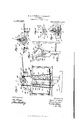
- Figure 1 is a side elevation of the invention.
- Fig. 2 is a front end view of same.
- Fig. 3 is an enlarged section on the line XX, Fig. 1.
- Fig. 4 is an enlarged section on the line YY, Fig. 1.
- Fig. 5 is a detail in side elevation of the automatic reversing mechanism.
- Fig. 6 is a detail in perspective of the trip-lever.
- Fig. 7 is a detail in vertical section of the traveling leaf actuator.
- A represents the frame of the machine which is supported on a pedestal B, which frame and pedestal may be of any suitable design or construction.
- a stationary shaft 2 having a portion of its length screw-threaded, as at 3, on which a nut 4 is mounted, as shown in Fig. 7 and surrounding the threaded portion 3 and the nut 4 is a cylinder 5 which is revolubly mount- Specification of Letters Patent.
- the stationary shaft 2 is adapted to be rotated continuously in either direction, as later described, by means of a motor 6 mounted on the frame A, or by any other suitable source of power.
- the cylinder 5 is slotted longitudinally, as at 7, through which slot a tubular projection 8 on the nut 4 extends; this projection 8 being engaged by the sides of the slot 7 so that the nut 4 will be rotated in synchronism with the cylinder 5, as the latter is rotated around the shaft 2.
- a bolt 9 Slidably mounted in the tubular member 8, on the nut 4, is a bolt 9, the outer end of which normally projects beyond the outer end of the member 8; a spring 10 in the member 8 bearing against the inner end of the bolt to retain it in its outermost position, and a pin 11 extending through the bolt riding in slots in the member 8 being provided to limit its outward movement.
- Means are provided for drawing the bolt 9 within the member 8 in opposition to the spring 10, which means are here shown as consisting of a cam plate or flange 12 which is adapted to engage the outer end of the pin 11 as the nut 4 and the member 8 are revolved and cause them and the bolt 9 to move backward in the member 8.
- the cam plate or flange 12 is formed on a sleeve 13 loosely mounted on the cylinder 5; the cylinder 5 being free to rotate in the sleeve 13, as later described.
- each plate-holder 14 is in parallel relation to the shaft 2, and each holder has a lug or projection 16 formed on its inner edge, which projection is so disposed as to be engaged by the bolt 9 when the latter is in its outermost position.
- the lugs or projections 16 on the adjacent leaf-holders 14 are arranged in an off-set, or stepped up, fashion in relation to each other, so that when the bolt 9 of the actuator is moved by the action of the screw 3 after engaging the lug or projection 16 on one leaf-holder, the projection 16 on the adjacent leaf-holder will be in line with the bolt 9 in the new position.
- the plate-holders 14 are supported on either side of the machine by means of buffers 17 mounted on parallel rods 18 supported in brackets formed on each side of the frame A, as shown in Figs. 2 and 3.
- the mechanism for rotating the cylinder 5 consists of a gear 19 on the cylinder 5 which is adapted to be engaged by either one of a pair of worm-gears 2020, disposed on opposite sides of the gear 19, which are designed to be alternately thrown in and out of engagement with the gear 19, as will be later described.
- the worm-gears 20.-20 are mounted on vertically disposed shafts 21-21 which have gears 2222 mounted on their lower ends, and which are supported in a rocking frame 23 pivoted at 24: on the frame A.
- the gears 2222 are disposed on opposite sides of a worm-gear 25 mounted on the drive shaft of themotor 6, and are in constant mesh therewith, from which it will be seen that when the motor 6 isin operation the worm-gears 2020 will be rotated continuously.
- Means are provided for rocking the frame 24- at predetermined intervals, so as to alternately throw first one and then the other of the worm-gears 2020 into. engagement with the gear 19 on the cylinder 5.
- rocking of theylever 26 is accomplished automatically by means controlled by the movement of the nut 1 on the worm 3, which means includes a pair of connected rocking arms 2929 arranged to extend on opposite sides of the lever 26 and pivoted at a point somedistance therebelow.
- the upper ends of the arms 2929 arepivotally attached to connecting rods 3030' which parallel the rods 18 and are connected therewith by means of blocks 3131
- the blocks 3131 are rigidly and adjustably mounted on the connecting rods 3030 and are slidably mounted on the rods 18; the block 31 on the rod 30 being adapted to be engaged by an arm 32 on the sleeve 13 as the latter is carried upward on the cylinder 5, so as to rock the arm 29 in a forward direction, and the block 31 on the rod 30' being adapted to be engaged by the arm 32 on the sleeve 13 as the latter is carried downward on the cylinder 5, so as to rock the arm 29 in a backward direction.
- a helical spring 33 is attached to the frame A and the arm 29' in such manner as to exert adownward pull on the latter so as to accelerate the movement of the arms 29-29 in either direction after the arms have been carried a certain distance by the slow action of the arm 32 on the sleeve 13, and to retain the arms 2929 in either their forward or rearward positions.
- Projections 3434 are formed on the opposite ends of the lever 26, which projections extend on opposite sides of the arm 29' and in the path of movement thereof in such manner that when the arm 29 is rocked in either direction by the quick action of the spring "33, the lever 26 will be caused to quickly rock in'a correspondingdirection and thereby-quickly throw one of the wormgears 2020- out of engagement with the gear 19 and the other gear into engagement therewith.
- a dog or pawl 35 pivoted on the frame A, is provided as a means for retaining the rocking lever 26 in either of its positions; a notch: or shoulder 35 engaging a projection 36 on the latch 26 when the rear end of the lever is uppermost, and a shoulder- 37 on the forward end of the pawl 35 engaging alip 38 on the forward end of the lever 26 when the latter is in its uppermost position.
- Thepawl 35 is released from engagement with the lever 26 by means of a pin .39 on the arm 29, which pin travels over a cam surface on the pawl 35 in such manner as to raise the pawl 35 when the arm 29 is traveling on either its forward or backward movement.
- the worm 25 is caused to revolve by setting the motorfi in motion which rotates the gears 2222, shafts 21 21 and worm-gears 20-20, ;as before described.
- the wormear-22 being engaged with the gear 19 on the cylinder 5 causes the latter to revolve on the shaft 2, which movement istransmitted to-the nut 4: and the bolt 9 mounted thereon.
- the actuating bolt 9 will be caused to travel back and forth on the shaft 2 so as to turn the series of leaf-holders, first to one side, then to the other, and that the leaf-holders will be in a state of rest for the period of time consumed by the bolt 9 in traversing approximately three-quarters of a revolution. This interval of rest gives an observer an opportunity to see the pictures or read the characters displayed on the sheets 15.
- a leaf-turner the combination with a series of hinged lELf-l10ld6IS, of a traveling actuator constructed and arranged to turn said leaf-holders successively, means for giving said actuator a continuous spiral movement first in one direction and then in the other direction, said means consisting of a nut on which said actuator is mounted and a stationary screw-threaded shaft on which the nut is mounted, a slotted cylinder on said stationary shaft, a gear on said cylinder, a continuously rotating worm-gear on each side of said gear, and automatic means by which first one worm-gear and then the other will be thrown in and out of mesh with said gear.
- a leaf-turner the combination with a series of hinged leaf-holders, of a traveling actuator constructed and arranged to turn said leaf-holders successively, means for giving said actuator a continuous spiral movement first in one direction and then in the other direction, said means consisting of a nut on which said actuator is mounted and a stationary screw-threaded shaft on which the nut is mounted, a slotted cylinder on said stationary shaft, a gear on said cylinder, a continuously rotating worm-gear on each side of said gear, a rocking frame, shafts on which the worm-gears are mounted supported in said frame, and means for rocking said frame at predetermined intervals.
- a traveling actuator constructed and arranged to turn said leaf-holders successively, means for giving said actuator a continuous spiral movement first in one direction and then in the other direction, said means consisting of a nut on which said actuator is mounted and a stationary screw-threaded shaft on which the nut is mounted, a slotted cylinder on said stationary shaft, a gear on said cylinder shaft, a continuously rotating worm-gear on each side of said gear, a rocking frame, shafts 011 which the worm-gears are mounted supported in said frame, and means for rocking said frame at predetermined intervals, said frame-rocking means controlled by the movement of said actuator.
- a traveling actuator adapted to engage said leaf-holders successively, consisting of a stationary threaded shaft, a nut thereon, a tubular projection on said nut, a bolt slidably mounted therein, means for rotating said nut, and means for advancing and retracting said bolt as the nut revolves.
- a traveling actuator adapted to engage said leaf-holders successively, consisting of a stationary threaded shaft, a nut thereon, a tubular projection on said nut, a bolt slidably mounted therein, means for rotating said nut, and means for advancing and retracting said bolt as the nut revolves, said means consisting of a resilient member in said tubular projection, a pin on said bolt and a cam surface adapted to bear against said pin.
- an actuator adapted to successively engage said leafholders, consisting of a retractable spring-actuated member, a nut on which said member is mounted, a screw-threaded shaft on which said nut is mounted, and means for advancing the nut on the threaded shaft in either direction.
- an actuator adapted to successively engage said leaf-holders, consisting of a retractable spring-actuated member, a nut on which said member is mounted, screw-threaded shaft on which said nut is mounted, means for rotating the nut on the threaded shaft in either direction, and means for retracting said springactuated member upon the rotation of the nut.
- a leaf-turner In a leaf-turner, the combination With a series of hinged leaves, of a leaf actuator having a spiral movement, means for giving the actuator said spiral movement, said means including a pair of oppositely acting driving gears, and means for automatically reversing the direction of travel of said actuator, said-reversing means including devices for determining which of said driving gears is to be-efiective.
- a leaf-turner the combination of a seriesof hinged leaf holders, a traveling actuator, astationary screw, and mechanism for operating said actuator, said mechanism including a worm-gear, a drive shaft on which said worm-gear is mounted, a pair of gears meshing with said worm-gear, shafts on which said gears are mounted, a worm gearon each of said shafts, a gear disposed between said last-named worm-gears, and means" for throwing first one worm-gear then the other into mesh with said lastnamed gear for-turning said hinged leaf holders first in one direction and then in the other.
- said mechanism including a worm-gear, a drive shaft on which said worm-gear is mounted, a pair of gears meshing with said worm-gear, shafts on which said gears are mounted, a worm gearon each of said shafts, a gear disposed between said last-named worm-gears, and means" for throwing first one worm-ge
- a leaf-turner the combination of aseries of hinged leaf holders, atraveling actuator, a stationary screw, and mechanism foroperating said actuator, said mechanism including a Worm-gear,- a drive shaft on Which said worm-gear is mounted, a pair of gears meshing with said worm-gear, shafts on which said gears are mounted, a"w0rm gear on each of said shafts, a'gear disposed between said last-named worm-gears, and
- said means including a rocking frame, a pin on said rocking frame carrying said pair of gears, a lever, a slot in said lever engaging said pin, and means for rocking said lever to actuate the rocking frame.
- a leaf-turner the combination of a series of hinged leaf holders, a traveling actuator, a stationary screw, and mechanism for operating said actuator, said mechanism including a worm-gear, a drive shaft on which said worm-gear is mounted,.a pair of gears meshing with said worm-gear, shafts on which said gears are mounted, a jworm-' gear on each of said shafts, a gear disposed between said last-named Worm-gears, and means for throwing first one worm-gear then the other into mesh with said last-named gear for turning said hinged leaf holders first in one direction and then in the other, said means including a rocking frame, a pin on said rocking frame, a lever, aslot in said lever engaging said pin, and means for rocking said lever to actuate the rocking frame, consisting of a rocking arm, a spring to exert a pull on said arm, and means for actuating said arm from a remote point.
Landscapes
- Transmission Devices (AREA)
Description
R. A. GIBSON & J. B. SARTOLOU. LEAF TURNER. 11 127227.
APPLICATION FILED MAY 29, 1911.
Patented Feb. 2, 1915.
2 SHEETS-SHEET 1.
.Zhven/ons; iaerf A. 6555022 4 .55 B Jarfulaa /fife .ZZe/r l y.
HE NORRIS PETERS C0,, PHOTOLITHQ. WASHING TON D. c.
LEAF TURNER. APPLICATION FILED MAY 29, 1911.
Patented Feb. 2, 1915.
2 SHEETS-SHEET 2.
.rlfllffrlfl'fll Flltrtlllff/Illll! THE NORRIS PETERS 60.. FHOTc-LITHO.. WASHINGTON. D. c.
UNITED STATES PATENT OFFICE.
I ROBERT A. GIBSON, OF BERKELEY, AND JOHN B. SARTOLOU, OF EMERYVILLE,
CALIFORNIA.
LEAF-TURNER.
Application filed May 29, 1911.
.To all 2071 am it may concern.
Be it known that we, ROBERT A. GIBSON, residing at Berkeley, Alameda county, California, and JOHN B. SAnToLoU, residing at Emeryville, Alameda county, California, both citizens of the United States, have invented new and useful Improvements in Leaf-Turners, of which the following is a specification.
This invention relates to a mechanical leaf-turner for holding and turning music, advertising cards, photographs, etc.
It is the object of this invention to provide a simple, practical, automatic, continuouslyoperating leaf-turner, which is adapted to be operated by means of an electric motor or other motive power, and which is especially suitable for use in displaying and eX- hibiting sheet pictorial illustrations, signs and the like, in succession.
Another object is to provide means in a leaf-turner by which the direction of rotation of the leaf turning mechanism will be automatically reversed after a predetermined number of leaves have been turned in one direction, so as to return the leaves successively in the other direction and so on; the series of leaves being turned first one way, then the other, so as to display each leaf a number of times by the continued operation of the machine.
The invention consists of the parts and the construction and combination of parts, as hereinafter more fully described and claimed, having reference to the accompanying drawings, in which Figure 1 is a side elevation of the invention. Fig. 2 is a front end view of same. Fig. 3 is an enlarged section on the line XX, Fig. 1. Fig. 4 is an enlarged section on the line YY, Fig. 1. Fig. 5 is a detail in side elevation of the automatic reversing mechanism. Fig. 6 is a detail in perspective of the trip-lever. Fig. 7 is a detail in vertical section of the traveling leaf actuator.
In the drawings A represents the frame of the machine which is supported on a pedestal B, which frame and pedestal may be of any suitable design or construction.
Rigidly mounted on the frame A is a stationary shaft 2, having a portion of its length screw-threaded, as at 3, on which a nut 4 is mounted, as shown in Fig. 7 and surrounding the threaded portion 3 and the nut 4 is a cylinder 5 which is revolubly mount- Specification of Letters Patent.
Patented Feb. 2, 1915.
Serial No. 630,012.
ed on the stationary shaft 2 and is adapted to be rotated continuously in either direction, as later described, by means of a motor 6 mounted on the frame A, or by any other suitable source of power. The cylinder 5 is slotted longitudinally, as at 7, through which slot a tubular projection 8 on the nut 4 extends; this projection 8 being engaged by the sides of the slot 7 so that the nut 4 will be rotated in synchronism with the cylinder 5, as the latter is rotated around the shaft 2. Slidably mounted in the tubular member 8, on the nut 4, is a bolt 9, the outer end of which normally projects beyond the outer end of the member 8; a spring 10 in the member 8 bearing against the inner end of the bolt to retain it in its outermost position, and a pin 11 extending through the bolt riding in slots in the member 8 being provided to limit its outward movement. Means are provided for drawing the bolt 9 within the member 8 in opposition to the spring 10, which means are here shown as consisting of a cam plate or flange 12 which is adapted to engage the outer end of the pin 11 as the nut 4 and the member 8 are revolved and cause them and the bolt 9 to move backward in the member 8. The cam plate or flange 12 is formed on a sleeve 13 loosely mounted on the cylinder 5; the cylinder 5 being free to rotate in the sleeve 13, as later described.
Pivotally mounted on the shaft 2 is a series of sheet holders 14, each of which consists of a pair of parallel clamping plates,
between which a card or sheet 15 may be rigidly held; these plates being mounted at each end on an arm which terminates in a sleeve loosely mounted on the shaft 2. The inner edge of the leaf holders 14 is in parallel relation to the shaft 2, and each holder has a lug or projection 16 formed on its inner edge, which projection is so disposed as to be engaged by the bolt 9 when the latter is in its outermost position. The lugs or projections 16 on the adjacent leaf-holders 14 are arranged in an off-set, or stepped up, fashion in relation to each other, so that when the bolt 9 of the actuator is moved by the action of the screw 3 after engaging the lug or projection 16 on one leaf-holder, the projection 16 on the adjacent leaf-holder will be in line with the bolt 9 in the new position. The plate-holders 14 are supported on either side of the machine by means of buffers 17 mounted on parallel rods 18 supported in brackets formed on each side of the frame A, as shown in Figs. 2 and 3.
The mechanism for rotating the cylinder 5 consists of a gear 19 on the cylinder 5 which is adapted to be engaged by either one of a pair of worm-gears 2020, disposed on opposite sides of the gear 19, which are designed to be alternately thrown in and out of engagement with the gear 19, as will be later described. The worm-gears 20.-20 are mounted on vertically disposed shafts 21-21 which have gears 2222 mounted on their lower ends, and which are supported in a rocking frame 23 pivoted at 24: on the frame A. The gears 2222 are disposed on opposite sides of a worm-gear 25 mounted on the drive shaft of themotor 6, and are in constant mesh therewith, from which it will be seen that when the motor 6 isin operation the worm-gears 2020 will be rotated continuously.
Means are provided for rocking the frame 24- at predetermined intervals, so as to alternately throw first one and then the other of the worm-gears 2020 into. engagement with the gear 19 on the cylinder 5. These meansconsist of a rocking lever 26 mounted on a member of the frame A, which lever has an angularly disposed groove 27 on its inner end which engages a pin 28 on the back of a vertical member on the rocking frame 24 in such manner that when the lever 26 is rocked backward and forward in one direction, the frame 2 1 will be caused to rock backward and forward in a direction at right angles to that of the movement of the lever 26.
The rocking of theylever 26 is accomplished automatically by means controlled by the movement of the nut 1 on the worm 3, which means includes a pair of connected rocking arms 2929 arranged to extend on opposite sides of the lever 26 and pivoted at a point somedistance therebelow. The upper ends of the arms 2929 arepivotally attached to connecting rods 3030' which parallel the rods 18 and are connected therewith by means of blocks 3131 The blocks 3131 are rigidly and adjustably mounted on the connecting rods 3030 and are slidably mounted on the rods 18; the block 31 on the rod 30 being adapted to be engaged by an arm 32 on the sleeve 13 as the latter is carried upward on the cylinder 5, so as to rock the arm 29 in a forward direction, and the block 31 on the rod 30' being adapted to be engaged by the arm 32 on the sleeve 13 as the latter is carried downward on the cylinder 5, so as to rock the arm 29 in a backward direction.
A helical spring 33 is attached to the frame A and the arm 29' in such manner as to exert adownward pull on the latter so as to accelerate the movement of the arms 29-29 in either direction after the arms have been carried a certain distance by the slow action of the arm 32 on the sleeve 13, and to retain the arms 2929 in either their forward or rearward positions.
Projections 3434 are formed on the opposite ends of the lever 26, which projections extend on opposite sides of the arm 29' and in the path of movement thereof in such manner that when the arm 29 is rocked in either direction by the quick action of the spring "33, the lever 26 will be caused to quickly rock in'a correspondingdirection and thereby-quickly throw one of the wormgears 2020- out of engagement with the gear 19 and the other gear into engagement therewith. f p
A dog or pawl 35, pivoted on the frame A, is provided as a means for retaining the rocking lever 26 in either of its positions; a notch: or shoulder 35 engaging a projection 36 on the latch 26 when the rear end of the lever is uppermost, and a shoulder- 37 on the forward end of the pawl 35 engaging alip 38 on the forward end of the lever 26 when the latter is in its uppermost position. Thepawl 35 is released from engagement with the lever 26 by means of a pin .39 on the arm 29, which pin travels over a cam surface on the pawl 35 in such manner as to raise the pawl 35 when the arm 29 is traveling on either its forward or backward movement.
In the operation of the invention the worm 25 is caused to revolve by setting the motorfi in motion which rotates the gears 2222, shafts 21 21 and worm-gears 20-20, ;as before described. The wormear-22 being engaged with the gear 19 on the cylinder 5 causes the latter to revolve on the shaft 2, which movement istransmitted to-the nut 4: and the bolt 9 mounted thereon. As the nute -is-rotated on the threads 3, it is caused to slQwly-advance upward on the shaft 2 carrying the bolt 9 and the sleeve 13 therewith, with the arm 32 on the sleeve 13 contacting with the underside of the bar 18, as shown in'Figs. 1 and 2. As the bolt 9 travels around the shaft 2- with the cylinder 5, it comesin-contact witha projection 16 on a leaf-holder 1 1, soas to cause the leafholder to turnaround the shaft 2 therewith. The moment the leaf-holder is carried a little beyond a vertical position by the bolt 9,
it falls to the opposite side of the shaft 2 1 where, ifitis the first leaf-holder of the series, it Will be broughtto a stop against the buffers 17; the other leaf-holders of the series beingsuccessively stacked thereon by the continued-rotation of the actuating bolt The bolt 9, after having turned a leafholder, as just described, is retracted into the tubular member 8 by the action of the cam plate -12,on the pin 11, asbefore described; this action withdrawing the bolt 9 clear of the projection 16 on the leaf-holder 14 just actuated. The bolt 9 is now moved up another step by means of the screw 3 and engages the projection 16 on the succeeding leaf-holder 1% and the operation is repeated. As the arm 32 nears the upper end of the shaft 2, it engages the block 31 and moves it along the rod 18, so as to throw the arm 29 over, as before described, to rock the frame C and thus throw the worm-gear 20 out of engagement with the gear 19 and throw the gear 20 into mesh therewith. This reverses the direction of rotation of the cylinder 5 and also changes the direction of movement of the nut a on the worm 3, so that the leaf-holders let, previously turned, will now be returned successively. In reversing the direction of rotation of the cylinder 5 and the actuating bolt 9, the sleeve 13 will be turned with the cylinder by reason of the bolt 9 contacting with the opposite end of the cam or flange 1'2, so that the arm will bear against the bar 18. As the arm 32 moves downward along the bar 18, it comes in contact with the block 31 and sets the reversing mechanism into operation again, as before described.
From the foregoing it will be seen that the actuating bolt 9 will be caused to travel back and forth on the shaft 2 so as to turn the series of leaf-holders, first to one side, then to the other, and that the leaf-holders will be in a state of rest for the period of time consumed by the bolt 9 in traversing approximately three-quarters of a revolution. This interval of rest gives an observer an opportunity to see the pictures or read the characters displayed on the sheets 15.
Having thus described my invention, what I claim and desire to secure by Letters Patent is 1. In a leaf-turner, the combination with a series of hinged lELf-l10ld6IS, of a traveling actuator constructed and arranged to turn said leaf-holders successively, means for giving said actuator a continuous spiral movement first in one direction and then in the other direction, said means consisting of a nut on which said actuator is mounted and a stationary screw-threaded shaft on which the nut is mounted, a slotted cylinder on said stationary shaft, a gear on said cylinder, a continuously rotating worm-gear on each side of said gear, and automatic means by which first one worm-gear and then the other will be thrown in and out of mesh with said gear.
2. In a leaf-turner, the combination with a series of hinged leaf-holders, of a traveling actuator constructed and arranged to turn said leaf-holders successively, means for giving said actuator a continuous spiral movement first in one direction and then in the other direction, said means consisting of a nut on which said actuator is mounted and a stationary screw-threaded shaft on which the nut is mounted, a slotted cylinder on said stationary shaft, a gear on said cylinder, a continuously rotating worm-gear on each side of said gear, a rocking frame, shafts on which the worm-gears are mounted supported in said frame, and means for rocking said frame at predetermined intervals.
3. In a leaf-turner, the combination with a series of hinged leaf-holders, of a traveling actuator constructed and arranged to turn said leaf-holders successively, means for giving said actuator a continuous spiral movement first in one direction and then in the other direction, said means consisting of a nut on which said actuator is mounted and a stationary screw-threaded shaft on which the nut is mounted, a slotted cylinder on said stationary shaft, a gear on said cylinder shaft, a continuously rotating worm-gear on each side of said gear, a rocking frame, shafts 011 which the worm-gears are mounted supported in said frame, and means for rocking said frame at predetermined intervals, said frame-rocking means controlled by the movement of said actuator.
-l. In a device of the character described having a series of hinged leaf-holders, a traveling actuator adapted to engage said leaf-holders successively, consisting of a stationary threaded shaft, a nut thereon, a tubular projection on said nut, a bolt slidably mounted therein, means for rotating said nut, and means for advancing and retracting said bolt as the nut revolves.
5. In a device of the character described having a series of hinged leaf-holders, a traveling actuator adapted to engage said leaf-holders successively, consisting of a stationary threaded shaft, a nut thereon, a tubular projection on said nut, a bolt slidably mounted therein, means for rotating said nut, and means for advancing and retracting said bolt as the nut revolves, said means consisting of a resilient member in said tubular projection, a pin on said bolt and a cam surface adapted to bear against said pin.
6. In a device of the character described having a series of' hinged leaf-holders, an actuator adapted to successively engage said leafholders, consisting of a retractable spring-actuated member, a nut on which said member is mounted, a screw-threaded shaft on which said nut is mounted, and means for advancing the nut on the threaded shaft in either direction.
7. In a device of the character described having a series of hinged leaf-holders, an actuator adapted to successively engage said leaf-holders, consisting of a retractable spring-actuated member, a nut on which said member is mounted, screw-threaded shaft on which said nut is mounted, means for rotating the nut on the threaded shaft in either direction, and means for retracting said springactuated member upon the rotation of the nut. 8. In a leaf-turner, the combination With a series of hinged leaves, of a leaf actuator having a spiral movement, means for giving the actuator said spiral movement, said means including a pair of oppositely acting driving gears, and means for automatically reversing the direction of travel of said actuator, said-reversing means including devices for determining which of said driving gears is to be-efiective. I
I 9. In a leaf-turner, the combination of a seriesof hinged leaf holders, a traveling actuator, astationary screw, and mechanism for operating said actuator, said mechanism including a worm-gear, a drive shaft on which said worm-gear is mounted, a pair of gears meshing with said worm-gear, shafts on which said gears are mounted, a worm gearon each of said shafts, a gear disposed between said last-named worm-gears, and means" for throwing first one worm-gear then the other into mesh with said lastnamed gear for-turning said hinged leaf holders first in one direction and then in the other. g 10. In a leaf-turner, the combination of aseries of hinged leaf holders, atraveling actuator, a stationary screw, and mechanism foroperating said actuator, said mechanism including a Worm-gear,- a drive shaft on Which said worm-gear is mounted, a pair of gears meshing with said worm-gear, shafts on which said gears are mounted, a"w0rm gear on each of said shafts, a'gear disposed between said last-named worm-gears, and
(Popies of patent may be obtained for five cents each, by addressing the 1'; are
means for throwing first one lworm gear then the other into mesh with said lastgnamed gear for turning said hinged leaf holders first in one direction and then in the other, said means including a rocking frame, a pin on said rocking frame carrying said pair of gears, a lever, a slot in said lever engaging said pin, and means for rocking said lever to actuate the rocking frame. j a 11. In a leaf-turner, the combination of a series of hinged leaf holders, a traveling actuator, a stationary screw, and mechanism for operating said actuator, said mechanism including a worm-gear, a drive shaft on which said worm-gear is mounted,.a pair of gears meshing with said worm-gear, shafts on which said gears are mounted, a jworm-' gear on each of said shafts, a gear disposed between said last-named Worm-gears, and means for throwing first one worm-gear then the other into mesh with said last-named gear for turning said hinged leaf holders first in one direction and then in the other, said means including a rocking frame, a pin on said rocking frame, a lever, aslot in said lever engaging said pin, and means for rocking said lever to actuate the rocking frame, consisting of a rocking arm, a spring to exert a pull on said arm, and means for actuating said arm from a remote point. 7
In testimony whereof we have hereunto set our hands in the presence of two subscribing witnesses. 1'
ROBERT A. GIBSON. JOHN B. SARTOLOU. IVitnesses I ESTHER A. I-IERRMAN, FRANCIS C. KELLoGe.
Commissioner of Patents.
Washington, I). G.
Priority Applications (1)
| Application Number | Priority Date | Filing Date | Title |
|---|---|---|---|
| US63001211A US1127227A (en) | 1911-05-29 | 1911-05-29 | Leaf-turner. |
Applications Claiming Priority (1)
| Application Number | Priority Date | Filing Date | Title |
|---|---|---|---|
| US63001211A US1127227A (en) | 1911-05-29 | 1911-05-29 | Leaf-turner. |
Publications (1)
| Publication Number | Publication Date |
|---|---|
| US1127227A true US1127227A (en) | 1915-02-02 |
Family
ID=3195380
Family Applications (1)
| Application Number | Title | Priority Date | Filing Date |
|---|---|---|---|
| US63001211A Expired - Lifetime US1127227A (en) | 1911-05-29 | 1911-05-29 | Leaf-turner. |
Country Status (1)
| Country | Link |
|---|---|
| US (1) | US1127227A (en) |
-
1911
- 1911-05-29 US US63001211A patent/US1127227A/en not_active Expired - Lifetime
Similar Documents
| Publication | Publication Date | Title |
|---|---|---|
| US1127227A (en) | Leaf-turner. | |
| US1069122A (en) | Advertising device. | |
| US786102A (en) | Calculator. | |
| US1723332A (en) | Said gold | |
| US940730A (en) | Engraving or duplicating machine. | |
| US1366548A (en) | Change-sign device | |
| US1732104A (en) | Autographic machine | |
| US1019770A (en) | Automatic sign. | |
| US352701A (en) | matteson | |
| US1581460A (en) | Picture exhibitor | |
| US1084121A (en) | Display apparatus. | |
| US1077788A (en) | Display-rack. | |
| US1220677A (en) | Ticket-delivering machine. | |
| US627952A (en) | Mechanism for moving films or webs intermittingly. | |
| US1024177A (en) | Advertising apparatus. | |
| US697376A (en) | Mechanical directory, &c. | |
| US552410A (en) | Picture-exhibitor | |
| US774527A (en) | Indexed mechanical directory. | |
| US1369120A (en) | Card-counting machine | |
| US942949A (en) | Music-leaf turner. | |
| US531018A (en) | brig-g-s | |
| US1747746A (en) | Machine for displaying advertising | |
| US699178A (en) | Advertising-sign. | |
| US550145A (en) | Music-leaf turner | |
| US697382A (en) | Mechanical directory. |