US11250828B2 - Felt array - Google Patents
Felt array Download PDFInfo
- Publication number
- US11250828B2 US11250828B2 US15/962,778 US201815962778A US11250828B2 US 11250828 B2 US11250828 B2 US 11250828B2 US 201815962778 A US201815962778 A US 201815962778A US 11250828 B2 US11250828 B2 US 11250828B2
- Authority
- US
- United States
- Prior art keywords
- sound
- dampening
- panels
- light fixture
- light
- Prior art date
- Legal status (The legal status is an assumption and is not a legal conclusion. Google has not performed a legal analysis and makes no representation as to the accuracy of the status listed.)
- Active, expires
Links
- 239000000463 material Substances 0.000 claims abstract description 26
- 238000000034 method Methods 0.000 claims description 17
- 229920000139 polyethylene terephthalate Polymers 0.000 claims description 15
- 239000005020 polyethylene terephthalate Substances 0.000 claims description 15
- 239000000835 fiber Substances 0.000 claims description 6
- 238000004519 manufacturing process Methods 0.000 claims description 5
- -1 polyethylene terephthalate Polymers 0.000 claims description 3
- 230000015572 biosynthetic process Effects 0.000 claims description 2
- 238000002592 echocardiography Methods 0.000 description 5
- 239000011521 glass Substances 0.000 description 4
- 230000008901 benefit Effects 0.000 description 3
- 239000002184 metal Substances 0.000 description 3
- 239000004033 plastic Substances 0.000 description 3
- 229920003023 plastic Polymers 0.000 description 3
- 238000009408 flooring Methods 0.000 description 2
- 230000006870 function Effects 0.000 description 2
- 239000002023 wood Substances 0.000 description 2
- 239000006096 absorbing agent Substances 0.000 description 1
- 230000001413 cellular effect Effects 0.000 description 1
- 230000000694 effects Effects 0.000 description 1
- 238000009950 felting Methods 0.000 description 1
- 239000003292 glue Substances 0.000 description 1
- 239000000779 smoke Substances 0.000 description 1
Images


Classifications
-
- G—PHYSICS
- G10—MUSICAL INSTRUMENTS; ACOUSTICS
- G10K—SOUND-PRODUCING DEVICES; METHODS OR DEVICES FOR PROTECTING AGAINST, OR FOR DAMPING, NOISE OR OTHER ACOUSTIC WAVES IN GENERAL; ACOUSTICS NOT OTHERWISE PROVIDED FOR
- G10K11/00—Methods or devices for transmitting, conducting or directing sound in general; Methods or devices for protecting against, or for damping, noise or other acoustic waves in general
- G10K11/16—Methods or devices for protecting against, or for damping, noise or other acoustic waves in general
- G10K11/162—Selection of materials
-
- F—MECHANICAL ENGINEERING; LIGHTING; HEATING; WEAPONS; BLASTING
- F21—LIGHTING
- F21S—NON-PORTABLE LIGHTING DEVICES; SYSTEMS THEREOF; VEHICLE LIGHTING DEVICES SPECIALLY ADAPTED FOR VEHICLE EXTERIORS
- F21S2/00—Systems of lighting devices, not provided for in main groups F21S4/00 - F21S10/00 or F21S19/00, e.g. of modular construction
-
- F—MECHANICAL ENGINEERING; LIGHTING; HEATING; WEAPONS; BLASTING
- F21—LIGHTING
- F21S—NON-PORTABLE LIGHTING DEVICES; SYSTEMS THEREOF; VEHICLE LIGHTING DEVICES SPECIALLY ADAPTED FOR VEHICLE EXTERIORS
- F21S8/00—Lighting devices intended for fixed installation
- F21S8/04—Lighting devices intended for fixed installation intended only for mounting on a ceiling or the like overhead structures
-
- F—MECHANICAL ENGINEERING; LIGHTING; HEATING; WEAPONS; BLASTING
- F21—LIGHTING
- F21V—FUNCTIONAL FEATURES OR DETAILS OF LIGHTING DEVICES OR SYSTEMS THEREOF; STRUCTURAL COMBINATIONS OF LIGHTING DEVICES WITH OTHER ARTICLES, NOT OTHERWISE PROVIDED FOR
- F21V15/00—Protecting lighting devices from damage
- F21V15/01—Housings, e.g. material or assembling of housing parts
-
- F—MECHANICAL ENGINEERING; LIGHTING; HEATING; WEAPONS; BLASTING
- F21—LIGHTING
- F21V—FUNCTIONAL FEATURES OR DETAILS OF LIGHTING DEVICES OR SYSTEMS THEREOF; STRUCTURAL COMBINATIONS OF LIGHTING DEVICES WITH OTHER ARTICLES, NOT OTHERWISE PROVIDED FOR
- F21V21/00—Supporting, suspending, or attaching arrangements for lighting devices; Hand grips
- F21V21/008—Suspending from a cable or suspension line
-
- F—MECHANICAL ENGINEERING; LIGHTING; HEATING; WEAPONS; BLASTING
- F21—LIGHTING
- F21V—FUNCTIONAL FEATURES OR DETAILS OF LIGHTING DEVICES OR SYSTEMS THEREOF; STRUCTURAL COMBINATIONS OF LIGHTING DEVICES WITH OTHER ARTICLES, NOT OTHERWISE PROVIDED FOR
- F21V21/00—Supporting, suspending, or attaching arrangements for lighting devices; Hand grips
- F21V21/14—Adjustable mountings
-
- G—PHYSICS
- G10—MUSICAL INSTRUMENTS; ACOUSTICS
- G10K—SOUND-PRODUCING DEVICES; METHODS OR DEVICES FOR PROTECTING AGAINST, OR FOR DAMPING, NOISE OR OTHER ACOUSTIC WAVES IN GENERAL; ACOUSTICS NOT OTHERWISE PROVIDED FOR
- G10K11/00—Methods or devices for transmitting, conducting or directing sound in general; Methods or devices for protecting against, or for damping, noise or other acoustic waves in general
- G10K11/002—Devices for damping, suppressing, obstructing or conducting sound in acoustic devices
-
- G—PHYSICS
- G10—MUSICAL INSTRUMENTS; ACOUSTICS
- G10K—SOUND-PRODUCING DEVICES; METHODS OR DEVICES FOR PROTECTING AGAINST, OR FOR DAMPING, NOISE OR OTHER ACOUSTIC WAVES IN GENERAL; ACOUSTICS NOT OTHERWISE PROVIDED FOR
- G10K11/00—Methods or devices for transmitting, conducting or directing sound in general; Methods or devices for protecting against, or for damping, noise or other acoustic waves in general
- G10K11/16—Methods or devices for protecting against, or for damping, noise or other acoustic waves in general
-
- F—MECHANICAL ENGINEERING; LIGHTING; HEATING; WEAPONS; BLASTING
- F21—LIGHTING
- F21Y—INDEXING SCHEME ASSOCIATED WITH SUBCLASSES F21K, F21L, F21S and F21V, RELATING TO THE FORM OR THE KIND OF THE LIGHT SOURCES OR OF THE COLOUR OF THE LIGHT EMITTED
- F21Y2115/00—Light-generating elements of semiconductor light sources
- F21Y2115/10—Light-emitting diodes [LED]
Definitions
- Light fixtures come in many different varieties and styles. Some light fixtures are relatively simple, and provide little more than a housing for a light bulb. Other light fixtures are ornate, with multi-faceted designs. Some light fixtures are designed for commercial settings, while others are designed for residential use. Coverings for light fixtures are often made of plastic, metal or glass. Glass light fixtures tend to irradiate most of the light generated by the light source, while other fixtures made of metal or plastic may diffuse or direct the light in specific directions. Light fixtures are used in nearly every room in a building and, as a result, many different configurations of styles and materials are available.
- Embodiments described herein are generally directed to a sound-dampening light fixture.
- the sound-dampening light fixture includes the following: a structural center portion that includes a housing for a light source, and at least one interconnecting ring that includes connection points for connecting panels to the interconnecting ring.
- the sound-dampening light fixture also includes panels arranged circumferentially around the structural center portion. The panels are connected to the interconnecting ring at the connection points. The panels are arranged at angles that are designed to dampen sound waves, and are constructed from material that further dampens sound waves coming into contact therewith.
- a method manufacturing a sound-dampening light fixture.
- the method includes providing a structural center portion that includes a housing for a light source.
- the method also includes positioning at least one interconnecting ring around the structural center portion, where the interconnecting ring has multiple connection points for connecting panels to the interconnecting ring.
- the method includes connecting the panels circumferentially around the structural center portion at the connection points of the interconnecting ring, where the panels are arranged at angles that are designed to dampen sound waves, and where at least parts of the panels are constructed from sound-dampening material.
- a sound-dampening lighting apparatus in another embodiment, includes an interior frame that provides structural support for external panels, as well as a hanging apparatus connected to the interior frame. Still further, the lighting apparatus includes an interconnecting ring that has connection points for connecting the external panels to the interior frame, where the panels extend laterally away from the interior frame. The lighting apparatus also includes lights mounted on the interior frame that are programmable to cast light in a variety of directions. A controller is also included which is electrically connected to the lights. The controller is configured to direct light from the lights in various directions as specified by a user or control routine.
- FIG. 1A illustrates a bottom perspective view of a sound-dampening light fixture.
- FIG. 1B illustrates a top perspective view of a sound-dampening light fixture.
- FIG. 1C illustrates a facing view of a sound-dampening light fixture.
- FIG. 1D illustrates a top view of a sound-dampening light fixture.
- FIG. 2A illustrates a side facing view of a single panel.
- FIG. 2B illustrates a front perspective view of the panel.
- FIG. 3A illustrates a side facing view of a single panel being slid into contact with an interconnecting ring.
- FIG. 3B illustrates a side facing view of the panel in contact with the interconnecting ring.
- FIG. 3C illustrates a side facing view in which the panel and the interconnecting ring include magnets for fastening.
- FIG. 4A illustrates an embodiment with a single interconnecting ring around a base structural member.
- FIG. 4B illustrates an embodiment with multiple interconnecting rings around the base structural member.
- FIG. 4C illustrates a top view of the base structural member and interconnecting rings, along with a light source.
- FIG. 4D illustrates a top view of the base structural member and interconnecting rings, along with an alternative light source.
- FIG. 5A illustrates a bottom perspective view of a sound-dampening light fixture that is linked to multiple other sound-dampening light fixtures in a generally pentagonal shape.
- FIG. 5B illustrates a top perspective view of the sound-dampening light fixture linked to multiple other sound-dampening light fixtures in a generally pentagonal shape.
- FIG. 5C illustrates a front facing view of the sound-dampening light fixture linked to multiple other sound-dampening light fixtures in a generally pentagonal shape.
- FIG. 5D illustrates a top view of the sound-dampening light fixture linked to multiple other sound-dampening light fixtures in a generally pentagonal shape.
- FIG. 6A illustrates a bottom perspective view of a sound-dampening light fixture that is linked to multiple other sound-dampening light fixtures in a generally circular shape.
- FIG. 6B illustrates a bottom perspective view of a sound-dampening light fixture that is linked to multiple other sound-dampening light fixtures in a generally triangular shape.
- FIG. 6C illustrates a bottom perspective view of a sound-dampening light fixture that is linked to multiple other sound-dampening light fixtures in a generally square shape.
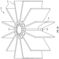
- FIG. 7 illustrates a bottom perspective view of a sound-dampening light fixture that includes panels having different sizes and/or shapes.
- FIG. 8 illustrates a flowchart of a method for manufacturing a sound-dampening light fixture.
- the embodiments described herein are generally directed to a sound-dampening light fixture.
- the sound-dampening light fixture includes the following: a structural center portion that includes a housing for a light source, and at least one interconnecting ring that includes connection points for connecting panels to the interconnecting ring.
- the sound-dampening light fixture also includes panels arranged circumferentially around the structural center portion. The panels are connected to the interconnecting ring at the connection points. The panels are arranged at angles that are designed to dampen sound waves, and are constructed from material that further dampens sound waves coming into contact therewith.
- a method manufacturing a sound-dampening light fixture.
- the method includes providing a structural center portion that includes a housing for a light source.
- the method also includes positioning at least one interconnecting ring around the structural center portion, where the interconnecting ring has multiple connection points for connecting panels to the interconnecting ring.
- the method includes connecting the panels circumferentially around the structural center portion at the connection points of the interconnecting ring, where the panels are arranged at angles that are designed to dampen sound waves, and where at least parts of the panels are constructed from sound-dampening material.
- a sound-dampening lighting apparatus in another embodiment, includes an interior frame that provides structural support for external panels, as well as a hanging apparatus connected to the interior frame. Still further, the lighting apparatus includes an interconnecting ring that has connection points for connecting the external panels to the interior frame, where the panels extend laterally away from the interior frame. The lighting apparatus also includes lights mounted on the interior frame that are programmable to cast light in a variety of directions. A controller is also included which is electrically connected to the lights. The controller is configured to direct light from the lights in various directions as specified by a user or control routine.
- a sound-dampening light fixture 100 may include multiple different panels 101 that are arranged around a structural center portion 102 .
- the panels 101 may be formed in substantially any shape or size, and may be arranged tightly together, or may be spaced apart.
- Each panel may have connecting portions 104 - 106 (shown in FIGS. 2A and 2B ) that connect to an interconnecting ring 103 of the sound-dampening light fixture 100 .
- a single interconnecting ring may be used ( 103 A or 103 B), or in other cases, multiple interconnecting rings may be used (e.g. 103 A and 103 B).
- the connecting portions 104 may include features such as grooves that allow the panels to be snap-fit to the interconnecting ring 103 .
- the connecting portions 104 on the panels may include snap connectors, tie connectors, interlocking connectors, magnetic connectors or other types of semi-permanent or permanent connectors.
- the panels 101 may be constructed using one or more materials that are designed to dampen sound.
- felted polyethylene terephthalate (PET) fibers may be used. PET fibers may be manufactured and felted using a variety of known felting processes. The resulting felted PET fibers can be press-formed or heat-formed into rigid structures, such as the panels shown in the sound-dampening light fixture of FIG. 1 .
- the panels 101 may be relatively thin (e.g. 1/16′′-1 ⁇ 8′′) to relatively thick (1 ⁇ 2′′-3 ⁇ 4′′), and may be made of a single material or a combination of materials. Indeed, some panels may include interior portions that are metal or plastic, which are then surrounded by a sound-dampening material such as felted PET. In other cases, the entire panel may be constructed using felted PET.
- the felted PET portions may be composed of recycled PET.
- the panels may be shaped in a specified manner that dampens sound.
- the panels 101 may be shaped like rectangles or squares, with defined corners and edges.
- the panel 101 is shaped like a fin, having rounded edges.
- Many shapes and sizes may be used, and each panel on a given fixture may be the same or a different shape and size.
- the shapes may be engineered to reduce echoes and reverberation within a room.
- the shape and size of the panels may be based on the size and shape of the room into which the panels (and the corresponding light fixture) are to be placed. Some sizes and shapes of panels may be more conducive to reducing echoes and reverberations in larger or smaller rooms, crowded or empty rooms, rooms with large amounts of glass or other highly reflective materials, etc. Accordingly, each sound-dampening light fixture may be specifically designed for a specific room or environment. The shape, size and thickness of each panel may be changed to accommodate different room types.
- FIGS. 1A-1D illustrate a single sound-dampening light fixture, shown from different perspectives.
- FIG. 1A shows a bottom perspective view of a sound-dampening light fixture
- FIG. 1B shows a top perspective view of the light fixture 100
- FIGS. 1C and 1D illustrate front facing and top views, respectively. Each of these views illustrates the sound-dampening light fixture 100 having 12 panels. It will be recognized, however, that substantially any number of panels may be used, and that the interconnecting rings 103 A/B may be designed to hold more panels than are actually used.
- the interconnecting rings 103 A/B were designed to hold 15 panels 101 , a user may use 10 of the slots, and leave the other five vacant.
- the 10 used slots may be aligned with the geometry of the room or environment of the space into which it is installed, thereby providing for enhanced sound-dampening capabilities.
- FIGS. 2A and 2B illustrate side and perspective views of a panel 101 .
- the panel 101 includes connecting portions 104 - 106 .
- Connecting portion 104 may be a tab or interstitial element that lies between an inner edge of the panel and a notch 105 .
- the notch 105 may be designed to allow a snap-fit connector (e.g. 107 ) of the interconnecting ring 103 to snap into the notch, while the connecting portion 104 holds the snap-fit connector in place, locked tight to the panel.
- a protruding element 106 may stick out from the inner end of the panel. This protruding element 106 may rest against the top or bottom surfaces of the respective interconnecting rings 103 A/B.
- the protruding element 106 may serve to vertically align the panel 101 with the structural center portion 102 , and may hold the panel in place once attached to the interconnecting ring.
- the panel 101 may be attached to the interconnecting rings 103 A/B via the connecting portion 104 and the notch 105 .
- the snap-fit connector 107 of the interconnecting ring 103 slides over the connecting portion 104 and into the notch 105 .
- the connecting portion and notch then work cooperatively to hold the panel in place.
- Other types of connections may also be used including hooks, screws, nails, rivets, clasps, tongue and groove fittings, or any other type of permanent or semi-permanent fastening.
- the fasteners can be magnets 108 A and 108 B.
- the panel has magnets 108 A
- the interconnecting ring 103 A has one or more corresponding magnets 108 B. These magnets are oppositely charged so they attract.
- the magnets may be sized appropriately to hold the panel 101 in place, while still allowing it to be separated if needed. For example, if the sound-dampening light fixture 100 is installed in a given room, and the acoustics are not improved, different shapes and sizes of panels may be easily swapped in and out using the magnetic connections. Once the correct sizes, shapes and number of panels are matched to the room's characteristics, an appropriate level of sound dampening may be provided.
- FIGS. 4A-4D illustrate embodiments of the structural center portion 102 , interconnecting rings 103 A/B, and different light sources 109 A and 109 B.
- a structural center portion 102 is illustrated as a cylinder. It will be recognized that the structural center portion 102 may be substantially any shape or size, including square, rectangular, triangular, circular or other shape.
- the interconnecting rings may be correspondingly shaped to fit around the structural center portion, depending on its shape. Thus, the interconnecting rings 103 may be square for square-shaped structural center portions.
- FIG. 4B illustrates an embodiment in which two interconnecting rings are used, although it will be understood that three, four, or more interconnecting rings may be used.
- the panels may be snap-fit, screwed, riveted, glued or magnetically attached directly to the structural center portion 102 . In such cases, interconnecting rings would not be used.
- FIG. 4C illustrates a top view of an embodiment in which a light source 109 A is mounted within the structural center portion 102 .
- the light source 109 may be an incandescent or LED light bulb, LED light strip (as in FIG. 4D ), or other type of light source.
- the light source 109 may be attached to a controller 111 via wiring 110 .
- the controller 111 may be configured to control the light source, including controlling the intensity of the light, as well as the directionality of the light. In some cases, for example, the light source may be directed to shine light upward, while in other cases the light is to be shone downward. In still other cases, the light is to be shone in other angular directions, or in both upward and downward directions. In this manner, a user may have full control of both the lighting and acoustics in a room, using a single sound-dampening lighting apparatus.
- FIGS. 5A-6C illustrate embodiments in which multiple sound-dampening light fixtures are connected to each other via linking members 201 .
- the linking members 201 are designed to fit into a slot where a panel 101 would normally reside.
- the linking members 201 may connect using snap connectors (or other types of connectors) that attach to corresponding connection 107 in the interconnecting members 103 .
- the linking members are more permanently attached to the structural center portion 102 (e.g. using glue, grommets or screws), while the panels remain interchangeable.
- linking members 201 and panels 101 are all interchangeable, a user may be able to design a large collective fixture (e.g. 200 A) made up of many different smaller fixtures (e.g. 100 A- 100 E) that is tailored to the acoustics of a given room.
- the collective feature may include different lengths and sizes of linking members, as well as different shapes and sizes of panels, forming many variations in overall structure.
- smaller light fixtures may be combined into larger collective fixtures that provide both sound-dampening and lighting functionality.
- FIGS. 5A & 5B illustrate bottom and top perspective views of an embodiment in which five different light fixtures are shown ( 100 A- 100 E), each being interconnected using a connecting member 201 to form a collective sound-dampening light fixture 200 A.
- the five light fixtures when combined, generally form a collective pentagonal light fixture.
- Each panel in the collective fixture is customizable in size or shape, or in the amount of sound-dampening material (e.g. felted PET).
- the interconnecting members 201 may connect to an interconnecting ring (or rings) of the sound-dampening light fixture.
- These interconnecting members 201 may also be composed of sound dampening material of varying thickness and size.
- many different sound-dampening light fixtures may be interlinked, and may be tailored to fit the acoustics of any given room or space.
- the collective light fixture may be expanded as needed to fill the entire room.
- each light source e.g. 109 A of FIG. 4C
- each light source 109 may be controlled individually, or may be controlled collectively for the group of fixtures.
- each light source 109 may have its own controller 111 and wiring 110 .
- the controllers may also be linked via wired connections or via wireless radio connections such as WiFi, Bluetooth, Zigbee, cellular or other radios.
- the controllers 111 may also be linked to a user's mobile device via an application that controls the lights including on or off status, directionality of the light source, intensity of the light source, or color (if color-changing lights are implemented).
- interlinked sound-dampening light fixtures act as both customizable, extensible lighting fixtures as well as acoustic management pieces. Additional sound-dampening light fixtures can be added to a room to add more light and ambience to the room, and at the same time reduce or manage echoes and reverberations.
- both the interconnecting members that connect the sound-dampening light fixtures together, as well as the panels on each of the fixtures are constructed using the same sound-dampening material (e.g. felted PET).
- the interconnecting members and the panels are constructed using different sound-dampening materials, or using different thicknesses or designs of sound-dampening materials to alter the acoustics in a given area.
- some panels may have angular, protruding portions that are further designed to reduce reverberations in a room.
- FIGS. 5C and 5D illustrate side and top views of the pentagonal collective light fixture 200 A of FIGS. 5A and 5B .
- FIG. 6A illustrates an embodiment in which the interconnecting members 201 are rounded, such that the overall shape of the collective light fixture 200 B, when using five individual fixtures ( 100 A- 100 E), is circular.
- FIG. 6B illustrates a collective light fixture 200 C which is triangular in shape, while fixture 200 D in FIG. 6C is square in shape.
- individual sound-dampening light fixtures such as fixture 100 of FIG. 1A , substantially any collective shape or design may be made.
- some of the individual light fixtures may be higher or lower than the other fixtures.
- the interconnecting members may be formed diagonally, and as such, may link to structural center portions that are hung in higher or lower positions.
- FIG. 7 illustrates an embodiment in which a sound-dampening light fixture 300 includes panels having different sizes. Indeed, as can be seen, panel 101 A is longer than panel 101 B. Other panels may be longer or shorter still. This may have an additional dampening effect on sound waves that come into contact with the fixture.
- the structural center portion of sound-dampening light fixture 300 provides support for interconnecting rings, and further provides support for the panels attached to the rings (e.g. 101 A and 101 B).
- the structural center portion also houses various light sources light bulbs, LED strips, or other light source housings. Substantially any type of light source may be used within the structural center portion of the sound-dampening light fixture.
- the structural center portion of sound-dampening light fixture 300 may be substantially cylindrical in shape.
- the structural center portion may be rectangular, square, triangular, or may be an oblong or hand-formed shape.
- the interconnecting rings may be correspondingly rectangular, square or triangle-shaped, or may be shaped to contour the oblong or hand-formed design.
- the interconnecting ring references a circular ring shape, it will be understood that the interconnecting ring may take a variety of different forms. Regardless of shape, the interconnecting ring allows panels to be connected to the structural center portion, whether removably or permanently.
- implementations of the invention as claimed when actually used in rooms, have been empirically shown to reduce the in-room acoustic coefficient (i.e. the noise reduction coefficient or NRC) to nearly 1.0.
- NRC noise reduction coefficient
- the sound-dampening light fixtures described herein can bring the NRC in a room to nearly 1.0, meaning that sounds do not echo or reverberate off of the sound-dampening light fixture.
- This high level of NRC is achieved despite the felted PET fibers having a substantially lower rating when tested alone (NRC was 0.65).
- the design of the panels, the fixture, and the combined collective fixture can have a great influence over how well sound is dampened in a given room.
- a sound-dampening light fixture (e.g. 100 of FIG. 1 ) includes the following: a structural center portion 102 that functions as a housing for a light source (e.g. 109 A of FIG. 4C ), one or more interconnecting rings ( 103 A/B) that have connection points 104 for connecting panels 101 to the interconnecting ring(s).
- the panels 101 are arranged circumferentially around the structural center portion, and are connected to the interconnecting ring at the connection points.
- the panels are arranged at angles that are designed to dampen sound waves by absorbing a portion of sound energy.
- the panels 101 are constructed from a material that further dampens sound waves that come into contact with the panels.
- Each room into which the sound-dampening light fixture 100 is to be installed is unique. Depending on whether the flooring has carpet or wood, or whether the walls have windows or doors, or other factors may dictate how conducive a room is to reverberations.
- the panels and the light fixture itself may be manufactured in a shape and design that is configured to dampen sound waves that come into contact with the light fixture. Rooms that are prone to reverberation (such as rooms with wood floors and multiple windows) may need a more aggressive design that dampens more sound, while other rooms (such as rooms with carpeted flooring and few windows) may not need as much sound dampening.
- a given sound-dampening light fixture may be connected to other sound-dampening light fixtures via interconnecting members that connect to connection points of the interconnecting rings.
- Each sound-dampening light fixture is modular, and can be connected to any number of other sound-dampening light fixtures.
- Both the panels and the interconnecting member that connects the sound-dampening light fixture and the other sound-dampening light fixture(s) may be constructed using a sound-dampening material such as felted polyethylene terephthalate (PET) fibers.
- PET polyethylene terephthalate
- Each panel 101 connects to the center structural portion 102 either directly or via an interconnecting ring or set of rings. These interconnecting rings may be placed at the top, bottom, middle or other part of the structural center portions.
- the structural center portion itself may be constructed from a translucent material that allows light to be emitted. Thus, when a light source 109 is placed within the structural center portion, light can travel through the center portion. Different thicknesses and levels of opacity may be used to subdue the light and provide a customized ambience for the room.
- the interior designer could select a specific type of material for the structural center portion.
- the designer could also link one or more sound-dampening light fixtures together in a formation that itself is designed to reduce sound vibrations, specifically for that room.
- the interior designer could use the controllers 111 in the light fixtures to specify where light is to be shone, at which intensity, and at which times.
- the interior designer (or operator of the room) may use an application to program the controllers, and the controllers may store the program in memory (e.g. in electronically erasable programmable memory (EEPROM)). Different programs may be stored and initialized by a user for different settings or functions. Using the light controller, a user can control many different properties of the light source, in real-time or in a pre-specified program.
- EEPROM electronically erasable programmable memory
- FIG. 8 illustrates a flow chart of a method 800 for manufacturing a sound-dampening light fixture.
- the method includes providing a structural center portion 102 that includes a housing for a light source ( 810 ), and positioning at least one interconnecting ring 103 around the structural center portion ( 820 ).
- the interconnecting ring has multiple connection points 104 for connecting one or more panels 101 to the interconnecting ring.
- the method also includes connecting the panels circumferentially around the structural center portion at the connection points of the interconnecting ring ( 830 ).
- the panels are arranged at angles that are designed to dampen sound waves. At least some parts of the panels are constructed from sound-dampening material.
- Each manufactured sound-dampening light fixture is modular and may be combined with other sound-dampening light fixtures using interconnecting panels.
- a combined structure may be manufactured that includes multiple modular sound-dampening light fixtures linked together via these interconnecting sound-dampening panels.
- Each sound-dampening light fixture may be attached to a ceiling mount via a support line. In such cases, a first end of the support line is attached to the ceiling mount and a second end of the support line is attached to a mount on the structural center portion 102 .
- the panels (including the interconnecting panels) may be attached to connection points of the interconnecting rings. These connection points may include snap-fit connections or magnetic connections where magnets embedded in the panels align with magnets embedded in the interconnecting rings.
- a sound-dampening lighting apparatus which includes the following: an interior frame (e.g. 102 ) that provides structural support for one or more external panels 101 , a hanging apparatus connected to the interior frame, and an interconnecting ring 103 that includes various connection points 104 for connecting the external panels to the interior frame.
- the panels extend laterally away from the interior frame, as shown in fixture 300 of FIG. 7 .
- the lighting apparatus in this example also includes lights (e.g. 109 ) mounted on the interior frame, where the lights are programmable to cast light in a variety of directions, and a controller electrically connected to the lights.
- the controller is configured to direct light emitting from the lights in specified directions or at specified intensities.
- the lights may be light emitting diode (LED) strips comprising multiple LED lights (as shown in FIG. 4D ).
- each of the panels in the light fixture is interchangeable, allowing users to switch panels of different sizes and shapes to dampen sound in a specified manner.
- the lighting apparatus may be designed for a specified room according to specific room characteristics. As such, a user may be able to specify a minimum amount of light that is to be provided by the lighting apparatus and a minimum amount of sound dampening is provided for the room.
- Each fixture in a collective fixture may be individually controlled to provide lighting in a specific direction or intensity. Specific sizes and shapes of panels may also be used to tune the acoustics in a room.
- the sound-dampening baffle and lighting apparatus may be designed, for example, to dampen sounds between approximately 250 and 4,000 Hz, which is the frequency range typically used by human voices. This ensures that as people speak to each other within the room, their voices do not reverberate or echo, reducing the likelihood that any given person will be hard to listen to or understand.
- the sound-dampening light fixtures provide the ability to cover the ceiling and/or walls with light sources that are aesthetically pleasing and acoustically functional, and still provide open access to the ceiling/wall and associated hardware such as sprinklers, smoke detectors, or other mechanical features.
Landscapes
- Engineering & Computer Science (AREA)
- General Engineering & Computer Science (AREA)
- Physics & Mathematics (AREA)
- Acoustics & Sound (AREA)
- Multimedia (AREA)
- Soundproofing, Sound Blocking, And Sound Damping (AREA)
- Non-Portable Lighting Devices Or Systems Thereof (AREA)
Abstract
Description
Claims (18)
Priority Applications (2)
| Application Number | Priority Date | Filing Date | Title |
|---|---|---|---|
| US15/962,778 US11250828B2 (en) | 2017-05-19 | 2018-04-25 | Felt array |
| US29/694,401 USD908923S1 (en) | 2018-04-25 | 2019-06-10 | Acoustic trellis system |
Applications Claiming Priority (2)
| Application Number | Priority Date | Filing Date | Title |
|---|---|---|---|
| US201762508529P | 2017-05-19 | 2017-05-19 | |
| US15/962,778 US11250828B2 (en) | 2017-05-19 | 2018-04-25 | Felt array |
Related Child Applications (1)
| Application Number | Title | Priority Date | Filing Date |
|---|---|---|---|
| US29/694,401 Continuation-In-Part USD908923S1 (en) | 2018-04-25 | 2019-06-10 | Acoustic trellis system |
Publications (2)
| Publication Number | Publication Date |
|---|---|
| US20180336875A1 US20180336875A1 (en) | 2018-11-22 |
| US11250828B2 true US11250828B2 (en) | 2022-02-15 |
Family
ID=64271928
Family Applications (1)
| Application Number | Title | Priority Date | Filing Date |
|---|---|---|---|
| US15/962,778 Active 2040-08-13 US11250828B2 (en) | 2017-05-19 | 2018-04-25 | Felt array |
Country Status (1)
| Country | Link |
|---|---|
| US (1) | US11250828B2 (en) |
Cited By (2)
| Publication number | Priority date | Publication date | Assignee | Title |
|---|---|---|---|---|
| USD1032019S1 (en) * | 2022-01-13 | 2024-06-18 | Arktura Llc | Architectural fixture |
| USD1061958S1 (en) * | 2022-08-19 | 2025-02-11 | Arktura Llc | Architectural fixture |
Families Citing this family (22)
| Publication number | Priority date | Publication date | Assignee | Title |
|---|---|---|---|---|
| USD917079S1 (en) | 2013-11-15 | 2021-04-20 | 3Form, Llc | Thin baffle |
| USD916348S1 (en) | 2013-11-15 | 2021-04-13 | 3Form, Llc | Light-weight lighting fixture |
| USD959030S1 (en) | 2013-11-15 | 2022-07-26 | 3Form, Llc | Baffle with slit end |
| USD915632S1 (en) | 2013-11-15 | 2021-04-06 | 3Form, Llc | Baffle with reduced height |
| US10889987B2 (en) | 2017-05-19 | 2021-01-12 | 3Form, Llc | Felt baffle with snap ends |
| USD915631S1 (en) | 2014-11-14 | 2021-04-06 | 3Form, Llc | Baffle with closed ends |
| USD915634S1 (en) | 2015-05-28 | 2021-04-06 | 3Form, Llc | Tall baffle |
| US20180283004A1 (en) * | 2016-06-30 | 2018-10-04 | Jason Gillette | Apparatus and system for dynamic acoustic drop ceiling system and methods thereof |
| US11211040B2 (en) | 2017-09-15 | 2021-12-28 | Focal Point, Llc | Modular fixture with integrated acoustic sound absorbing housing |
| USD888600S1 (en) * | 2017-11-30 | 2020-06-30 | Netta WEINROTH | Sculpture |
| USD888599S1 (en) * | 2017-11-30 | 2020-06-30 | Netta WEINROTH | Sculpture |
| USD888601S1 (en) * | 2017-11-30 | 2020-06-30 | Netta WEINROTH | Sculpture |
| US11578858B2 (en) | 2018-09-21 | 2023-02-14 | Fischer Lighting Holding Aps | Modular lighting device |
| US10672376B1 (en) | 2019-04-01 | 2020-06-02 | Eaton Intelligent Power Limited | Acoustic luminaires |
| WO2021151783A1 (en) * | 2020-01-27 | 2021-08-05 | Signify Holding B.V. | Luminaire with sound dampening panel |
| IT202000001534A1 (en) * | 2020-01-28 | 2021-07-28 | Avl Pro Sas Di Cavagnero Germano & C | MULTISFACETED ACOUSTIC ABSORBER |
| US11377845B2 (en) * | 2020-04-15 | 2022-07-05 | Usg Interiors, Llc | Acoustic baffle assembly |
| IT202000024448A1 (en) * | 2020-10-16 | 2022-04-16 | Benedetto Davide Di | LAMELLAR ACOUSTIC LAMP |
| USD1062002S1 (en) | 2022-08-22 | 2025-02-11 | 3Form, Llc | X-shaped light fixture |
| USD1054617S1 (en) | 2022-08-22 | 2024-12-17 | 3Form, Llc | T-shaped light fixture |
| USD1062004S1 (en) | 2022-08-22 | 2025-02-11 | 3Form, Llc | Y-shaped light fixture |
| USD1062003S1 (en) | 2022-08-22 | 2025-02-11 | 3Form, Llc | Hexagonal-shaped light fixture |
Citations (10)
| Publication number | Priority date | Publication date | Assignee | Title |
|---|---|---|---|---|
| US3364349A (en) * | 1965-04-12 | 1968-01-16 | Sidney R. Witz | Lamp shade construction |
| FR2405427A1 (en) * | 1977-10-07 | 1979-05-04 | Leviel Jean Luc | Lamp shade which is foldable for storage - consists of plastics sheet with channel strips which snap over mounting rings |
| USD270094S (en) | 1980-10-23 | 1983-08-09 | Hunter Douglas International N.V. | Decorative slat assembly for a suspended ceiling or the like |
| US6780356B1 (en) * | 1999-10-01 | 2004-08-24 | Awi Licensing Company | Method for producing an inorganic foam structure for use as a durable acoustical panel |
| US9038326B2 (en) | 2012-12-06 | 2015-05-26 | Awi Licensing Company | Ceiling system |
| US9163402B2 (en) | 2011-06-13 | 2015-10-20 | Arktura Llc | Suspended architectural structure |
| US20150366020A1 (en) * | 2013-01-16 | 2015-12-17 | Lg Electronics Inc. | Lighting apparatus |
| US9469998B1 (en) | 2014-01-28 | 2016-10-18 | Plastic Components, Inc. | Wall lath with self-furring ridges |
| US9506249B2 (en) | 2011-06-13 | 2016-11-29 | Arktura, Llc | System and method for a supported architectural design |
| USD777944S1 (en) | 2015-06-23 | 2017-01-31 | Arktura, Llc | Architectural ceiling fixture module |
-
2018
- 2018-04-25 US US15/962,778 patent/US11250828B2/en active Active
Patent Citations (10)
| Publication number | Priority date | Publication date | Assignee | Title |
|---|---|---|---|---|
| US3364349A (en) * | 1965-04-12 | 1968-01-16 | Sidney R. Witz | Lamp shade construction |
| FR2405427A1 (en) * | 1977-10-07 | 1979-05-04 | Leviel Jean Luc | Lamp shade which is foldable for storage - consists of plastics sheet with channel strips which snap over mounting rings |
| USD270094S (en) | 1980-10-23 | 1983-08-09 | Hunter Douglas International N.V. | Decorative slat assembly for a suspended ceiling or the like |
| US6780356B1 (en) * | 1999-10-01 | 2004-08-24 | Awi Licensing Company | Method for producing an inorganic foam structure for use as a durable acoustical panel |
| US9163402B2 (en) | 2011-06-13 | 2015-10-20 | Arktura Llc | Suspended architectural structure |
| US9506249B2 (en) | 2011-06-13 | 2016-11-29 | Arktura, Llc | System and method for a supported architectural design |
| US9038326B2 (en) | 2012-12-06 | 2015-05-26 | Awi Licensing Company | Ceiling system |
| US20150366020A1 (en) * | 2013-01-16 | 2015-12-17 | Lg Electronics Inc. | Lighting apparatus |
| US9469998B1 (en) | 2014-01-28 | 2016-10-18 | Plastic Components, Inc. | Wall lath with self-furring ridges |
| USD777944S1 (en) | 2015-06-23 | 2017-01-31 | Arktura, Llc | Architectural ceiling fixture module |
Non-Patent Citations (4)
| Title |
|---|
| IP.com English translation of FR-2405427-A1 (Year: 1979). * |
| Vapor Echo Cylinder (LX-VEC) data sheet (Year: 2013). * |
| Vapor Echo Cylinder (LX-VEC) date screen shoot (Year: 2013). * |
| Vapor Echo Cylinder (LX-VEC) installation instructions (Year: 2013). * |
Cited By (3)
| Publication number | Priority date | Publication date | Assignee | Title |
|---|---|---|---|---|
| USD1032019S1 (en) * | 2022-01-13 | 2024-06-18 | Arktura Llc | Architectural fixture |
| USD1059640S1 (en) | 2022-01-13 | 2025-01-28 | Arktura Llc | Architectural fixture |
| USD1061958S1 (en) * | 2022-08-19 | 2025-02-11 | Arktura Llc | Architectural fixture |
Also Published As
| Publication number | Publication date |
|---|---|
| US20180336875A1 (en) | 2018-11-22 |
Similar Documents
| Publication | Publication Date | Title |
|---|---|---|
| US11250828B2 (en) | Felt array | |
| US10876290B2 (en) | Felt baffle with snap ends | |
| US7303305B2 (en) | Acoustic light emitting module | |
| US5995634A (en) | Speaker and lamp combination | |
| US8967823B2 (en) | Combination light diffuser and acoustical treatment and listening room including such fixtures | |
| US10984775B2 (en) | Light fixture for absorbing sound energy | |
| US7066613B2 (en) | Sound and light apparatus | |
| US10313771B2 (en) | Loudspeaker mounting system | |
| JP2004084310A (en) | Wiring structure | |
| US20020136000A1 (en) | Built-in lamp apparatus for suspended ceilings | |
| JP6814884B1 (en) | Sound adjustment shelf | |
| WO2019115598A1 (en) | Device comprising a microphone unit | |
| KR101786847B1 (en) | Framed-type sound-absorbing panels | |
| US9307849B2 (en) | Modular mirror chassis apparatuses and methods | |
| JP6503651B2 (en) | Speaker device | |
| US20220005448A1 (en) | Acoustic enclosure | |
| CN211345019U (en) | Acousto-optic integrated ceiling lamp | |
| KR200463617Y1 (en) | lamp with a speaker | |
| JP4730161B2 (en) | Ceiling structure of living room | |
| CN219508951U (en) | Lighting system convenient to installation | |
| JP7565507B2 (en) | Building Materials | |
| CN217871338U (en) | Indoor lighting system that can improve space utilization | |
| Brawata et al. | Effect of stage curtain legs arrangement on sound distribution in opera houses | |
| CN111022990A (en) | A sound and light integrated ceiling lamp | |
| JP2024051285A (en) | Indirect lighting structure |
Legal Events
| Date | Code | Title | Description |
|---|---|---|---|
| AS | Assignment |
Owner name: 3FORM LLC., UTAH Free format text: ASSIGNMENT OF ASSIGNORS INTEREST;ASSIGNORS:PATTERSON, CALEB;MARTIN, GUILLAUME;REEL/FRAME:045636/0498 Effective date: 20180425 |
|
| FEPP | Fee payment procedure |
Free format text: ENTITY STATUS SET TO UNDISCOUNTED (ORIGINAL EVENT CODE: BIG.); ENTITY STATUS OF PATENT OWNER: LARGE ENTITY |
|
| STPP | Information on status: patent application and granting procedure in general |
Free format text: DOCKETED NEW CASE - READY FOR EXAMINATION |
|
| STPP | Information on status: patent application and granting procedure in general |
Free format text: NON FINAL ACTION MAILED |
|
| STPP | Information on status: patent application and granting procedure in general |
Free format text: NOTICE OF ALLOWANCE MAILED -- APPLICATION RECEIVED IN OFFICE OF PUBLICATIONS |
|
| STPP | Information on status: patent application and granting procedure in general |
Free format text: PUBLICATIONS -- ISSUE FEE PAYMENT VERIFIED |
|
| STCF | Information on status: patent grant |
Free format text: PATENTED CASE |
|
| AS | Assignment |
Owner name: JPMORGAN CHASE BANK, N.A., AS ADMINISTRATIVE AGENT, NEW YORK Free format text: INTELLECTUAL PROPERTY SECURITY AGREEMENT;ASSIGNORS:3FORM, LLC;3 DAY BLINDS LLC;COMFORTEX CORPORATION;AND OTHERS;REEL/FRAME:061958/0711 Effective date: 20221114 |
|
| AS | Assignment |
Owner name: 3FORM, LLC, UTAH Free format text: RELEASE BY SECURED PARTY;ASSIGNOR:JPMORGAN CHASE BANK, N.A., AS ADMINISTRATIVE AGENT;REEL/FRAME:067375/0581 Effective date: 20240426 |
|
| AS | Assignment |
Owner name: BANK OF AMERICA, N.A., AS THE COLLATERAL AGENT, NORTH CAROLINA Free format text: SECURITY INTEREST;ASSIGNOR:3FORM, LLC;REEL/FRAME:067725/0153 Effective date: 20221207 |