US11241827B2 - Method and apparatus for solid freeform fabrication of objects with improved resolution - Google Patents
Method and apparatus for solid freeform fabrication of objects with improved resolution Download PDFInfo
- Publication number
- US11241827B2 US11241827B2 US15/568,738 US201615568738A US11241827B2 US 11241827 B2 US11241827 B2 US 11241827B2 US 201615568738 A US201615568738 A US 201615568738A US 11241827 B2 US11241827 B2 US 11241827B2
- Authority
- US
- United States
- Prior art keywords
- powder
- powder material
- layer
- build platform
- resin
- Prior art date
- Legal status (The legal status is an assumption and is not a legal conclusion. Google has not performed a legal analysis and makes no representation as to the accuracy of the status listed.)
- Active, expires
Links
Images


Classifications
-
- B—PERFORMING OPERATIONS; TRANSPORTING
- B29—WORKING OF PLASTICS; WORKING OF SUBSTANCES IN A PLASTIC STATE IN GENERAL
- B29C—SHAPING OR JOINING OF PLASTICS; SHAPING OF MATERIAL IN A PLASTIC STATE, NOT OTHERWISE PROVIDED FOR; AFTER-TREATMENT OF THE SHAPED PRODUCTS, e.g. REPAIRING
- B29C64/00—Additive manufacturing, i.e. manufacturing of three-dimensional [3D] objects by additive deposition, additive agglomeration or additive layering, e.g. by 3D printing, stereolithography or selective laser sintering
- B29C64/10—Processes of additive manufacturing
- B29C64/165—Processes of additive manufacturing using a combination of solid and fluid materials, e.g. a powder selectively bound by a liquid binder, catalyst, inhibitor or energy absorber
-
- B—PERFORMING OPERATIONS; TRANSPORTING
- B29—WORKING OF PLASTICS; WORKING OF SUBSTANCES IN A PLASTIC STATE IN GENERAL
- B29C—SHAPING OR JOINING OF PLASTICS; SHAPING OF MATERIAL IN A PLASTIC STATE, NOT OTHERWISE PROVIDED FOR; AFTER-TREATMENT OF THE SHAPED PRODUCTS, e.g. REPAIRING
- B29C64/00—Additive manufacturing, i.e. manufacturing of three-dimensional [3D] objects by additive deposition, additive agglomeration or additive layering, e.g. by 3D printing, stereolithography or selective laser sintering
- B29C64/10—Processes of additive manufacturing
- B29C64/106—Processes of additive manufacturing using only liquids or viscous materials, e.g. depositing a continuous bead of viscous material
- B29C64/124—Processes of additive manufacturing using only liquids or viscous materials, e.g. depositing a continuous bead of viscous material using layers of liquid which are selectively solidified
- B29C64/129—Processes of additive manufacturing using only liquids or viscous materials, e.g. depositing a continuous bead of viscous material using layers of liquid which are selectively solidified characterised by the energy source therefor, e.g. by global irradiation combined with a mask
-
- B—PERFORMING OPERATIONS; TRANSPORTING
- B29—WORKING OF PLASTICS; WORKING OF SUBSTANCES IN A PLASTIC STATE IN GENERAL
- B29C—SHAPING OR JOINING OF PLASTICS; SHAPING OF MATERIAL IN A PLASTIC STATE, NOT OTHERWISE PROVIDED FOR; AFTER-TREATMENT OF THE SHAPED PRODUCTS, e.g. REPAIRING
- B29C64/00—Additive manufacturing, i.e. manufacturing of three-dimensional [3D] objects by additive deposition, additive agglomeration or additive layering, e.g. by 3D printing, stereolithography or selective laser sintering
- B29C64/20—Apparatus for additive manufacturing; Details thereof or accessories therefor
- B29C64/264—Arrangements for irradiation
- B29C64/277—Arrangements for irradiation using multiple radiation means, e.g. micromirrors or multiple light-emitting diodes [LED]
-
- B—PERFORMING OPERATIONS; TRANSPORTING
- B29—WORKING OF PLASTICS; WORKING OF SUBSTANCES IN A PLASTIC STATE IN GENERAL
- B29C—SHAPING OR JOINING OF PLASTICS; SHAPING OF MATERIAL IN A PLASTIC STATE, NOT OTHERWISE PROVIDED FOR; AFTER-TREATMENT OF THE SHAPED PRODUCTS, e.g. REPAIRING
- B29C64/00—Additive manufacturing, i.e. manufacturing of three-dimensional [3D] objects by additive deposition, additive agglomeration or additive layering, e.g. by 3D printing, stereolithography or selective laser sintering
- B29C64/20—Apparatus for additive manufacturing; Details thereof or accessories therefor
- B29C64/205—Means for applying layers
- B29C64/214—Doctor blades
-
- B—PERFORMING OPERATIONS; TRANSPORTING
- B29—WORKING OF PLASTICS; WORKING OF SUBSTANCES IN A PLASTIC STATE IN GENERAL
- B29C—SHAPING OR JOINING OF PLASTICS; SHAPING OF MATERIAL IN A PLASTIC STATE, NOT OTHERWISE PROVIDED FOR; AFTER-TREATMENT OF THE SHAPED PRODUCTS, e.g. REPAIRING
- B29C64/00—Additive manufacturing, i.e. manufacturing of three-dimensional [3D] objects by additive deposition, additive agglomeration or additive layering, e.g. by 3D printing, stereolithography or selective laser sintering
- B29C64/20—Apparatus for additive manufacturing; Details thereof or accessories therefor
- B29C64/205—Means for applying layers
- B29C64/218—Rollers
-
- B—PERFORMING OPERATIONS; TRANSPORTING
- B29—WORKING OF PLASTICS; WORKING OF SUBSTANCES IN A PLASTIC STATE IN GENERAL
- B29C—SHAPING OR JOINING OF PLASTICS; SHAPING OF MATERIAL IN A PLASTIC STATE, NOT OTHERWISE PROVIDED FOR; AFTER-TREATMENT OF THE SHAPED PRODUCTS, e.g. REPAIRING
- B29C64/00—Additive manufacturing, i.e. manufacturing of three-dimensional [3D] objects by additive deposition, additive agglomeration or additive layering, e.g. by 3D printing, stereolithography or selective laser sintering
- B29C64/30—Auxiliary operations or equipment
- B29C64/307—Handling of material to be used in additive manufacturing
- B29C64/321—Feeding
- B29C64/329—Feeding using hoppers
-
- B—PERFORMING OPERATIONS; TRANSPORTING
- B33—ADDITIVE MANUFACTURING TECHNOLOGY
- B33Y—ADDITIVE MANUFACTURING, i.e. MANUFACTURING OF THREE-DIMENSIONAL [3-D] OBJECTS BY ADDITIVE DEPOSITION, ADDITIVE AGGLOMERATION OR ADDITIVE LAYERING, e.g. BY 3-D PRINTING, STEREOLITHOGRAPHY OR SELECTIVE LASER SINTERING
- B33Y10/00—Processes of additive manufacturing
-
- B—PERFORMING OPERATIONS; TRANSPORTING
- B33—ADDITIVE MANUFACTURING TECHNOLOGY
- B33Y—ADDITIVE MANUFACTURING, i.e. MANUFACTURING OF THREE-DIMENSIONAL [3-D] OBJECTS BY ADDITIVE DEPOSITION, ADDITIVE AGGLOMERATION OR ADDITIVE LAYERING, e.g. BY 3-D PRINTING, STEREOLITHOGRAPHY OR SELECTIVE LASER SINTERING
- B33Y30/00—Apparatus for additive manufacturing; Details thereof or accessories therefor
-
- G—PHYSICS
- G03—PHOTOGRAPHY; CINEMATOGRAPHY; ANALOGOUS TECHNIQUES USING WAVES OTHER THAN OPTICAL WAVES; ELECTROGRAPHY; HOLOGRAPHY
- G03F—PHOTOMECHANICAL PRODUCTION OF TEXTURED OR PATTERNED SURFACES, e.g. FOR PRINTING, FOR PROCESSING OF SEMICONDUCTOR DEVICES; MATERIALS THEREFOR; ORIGINALS THEREFOR; APPARATUS SPECIALLY ADAPTED THEREFOR
- G03F7/00—Photomechanical, e.g. photolithographic, production of textured or patterned surfaces, e.g. printing surfaces; Materials therefor, e.g. comprising photoresists; Apparatus specially adapted therefor
- G03F7/0037—Production of three-dimensional images
-
- B—PERFORMING OPERATIONS; TRANSPORTING
- B29—WORKING OF PLASTICS; WORKING OF SUBSTANCES IN A PLASTIC STATE IN GENERAL
- B29C—SHAPING OR JOINING OF PLASTICS; SHAPING OF MATERIAL IN A PLASTIC STATE, NOT OTHERWISE PROVIDED FOR; AFTER-TREATMENT OF THE SHAPED PRODUCTS, e.g. REPAIRING
- B29C35/00—Heating, cooling or curing, e.g. crosslinking or vulcanising; Apparatus therefor
- B29C35/02—Heating or curing, e.g. crosslinking or vulcanizing during moulding, e.g. in a mould
- B29C35/08—Heating or curing, e.g. crosslinking or vulcanizing during moulding, e.g. in a mould by wave energy or particle radiation
- B29C35/0805—Heating or curing, e.g. crosslinking or vulcanizing during moulding, e.g. in a mould by wave energy or particle radiation using electromagnetic radiation
- B29C2035/0838—Heating or curing, e.g. crosslinking or vulcanizing during moulding, e.g. in a mould by wave energy or particle radiation using electromagnetic radiation using laser
Definitions
- the subject matter described herein generally relates to devices and methods for the solid freeform fabrication of objects from metal, plastic, ceramic, and composite materials comprising combinations of one or more types of material.
- additive manufacturing also known as solid freeform fabrication (SFF), 3D printing (3DP), direct digital manufacturing (DDM), and solid imaging
- SFF solid freeform fabrication
- DDM direct digital manufacturing
- solid imaging has increasingly become a widely adopted method of prototyping both visually demonstrative and functional parts. In some instances, this has become a cost effective means for production manufacturing as well.
- SFF is accomplished in a layerwise fashion, where a digital model is split into horizontal slices, and each slice is produced as a 2D image on a build surface.
- the sequential fabrication of these slices produces an aggregate collection of thin layers which collectively compose the 3 dimensional object represented by the digital model.
- CNC Computer Numerically Controlled
- SFF has markedly reduced production time and cost, and as such has been widely adopted for research and development purposes where low volume production with traditional means would be exceedingly expensive.
- SFF devices generally require less expertise to operate when compared to CNC machines.
- the cost of individual parts produced from CNC machines is generally higher, owing to longer setup times and higher costs of machine operation. CNC-produced parts will often have stronger and more detailed features than SFF-produced parts, which may make them desirable for some applications.
- SFF techniques can produce parts with the resolution and functionality of CNC-produced parts, the usage of SFF in part production will remain constrained.
- SFF stereolithography
- SDM selective deposition modeling
- FDM fused deposition modeling
- SLS selective laser sintering
- Embodiments of a device for solid freeform fabrication and associated methods are herein disclosed for the production of plastic, metal, and ceramic parts for a variety of applications.
- the SFF device disclosed herein may include a surface for receiving layers of material for production of a 3-dimensional solid representation of a digital model, a component or components for depositing the required layers of build material, and a component or components for imaging the build material into cross sections representative of data contained in a digital model.
- the build material is composed of a particulate material and a photocurable resin material, deposited sequentially in any order. The combination of these materials at the build surface overcomes the rheological constraints of aforementioned devices which have been used to produce powder composite parts.
- imaging techniques utilized for layer imaging may involve a combination of coarse bulk imaging and higher resolution detailed imaging techniques to improve imaging speed while maintaining image resolution.
- the device described below may utilize any of a variety of particulate materials, including but not limited to ceramics, plastics, or metals, as one of the build materials.
- Parts produced from this device may be treated after the build process is complete to facilitate bonding between adjacent particles.
- Such treatment includes but is not limited to thermal, chemical, and pressure treatment, and combinations of these.
- the results of this fabrication and treatment process include but are not limited to solid metal parts, solid ceramic parts, porous metal parts, porous ceramic parts, solid composite plastic parts, and composite parts comprising one or more types of material.
- Material deposition of particulate material may be achieved through several means, including but not limited to spreading via a blade mechanism, electrostatic deposition on a transfer surface followed by deposition to a build surface, and electrostatic deposition to a compressing roller followed by deposition to the build surface.
- material deposition of photocurable resin may be achieved through several means, including but not limited to droplet deposition from an inkjet printhead, ejection of resin onto a blade device used for leveling particulate material and infusion of particulate material with resin material, ejection of resin onto a roller device used for infusion of resin into particulate material, and transfer of resin from a reservoir onto a transfer mechanism, such as a brush, sponge, or film, which subsequently deposits resin onto a deposition mechanism, such as a roller or blade device, followed by deposition of the resin material at the build surface.
- Material deposition and combination may occur at the build surface, or within any of the aforementioned material deposition devices, such as rollers and blades, such that the net result is the production of a layer of particulate material infused with a photocurable resin.
- Layer imaging may be achieved through several means, including but not limited to bulk imaging with a programmable planar light source, such as a DLP projector, possibly coupled with the vectoring motion of a high resolution laser light source for imaging details, and bulk imaging with a rastering laser source with a larger beam diameter than a secondary laser light source used for detailed imaging.
- a programmable planar light source such as a DLP projector
- Such imaging techniques may generally follow the processing of data representative of a three dimensional object by slicing the object into layers, deriving data representative of border portions of the layer data and data representative of the interior portions of the layer data, and using the interior portion data for bulk imaging, and using the border portion data for detailed imaging.
- a solid freeform fabrication device such that composite objects composed of particulate material and resin material may be produced from digital data representative of a given three dimensional object.
- a SFF device which utilizes bulk deposition techniques for production of layers of material.
- a SFF device which combines particulate material with photocurable resin material for production of composite layers of material.
- a SFF device which allows for interchangeability of material components to enable the use of a wide variety of material combinations.
- a SFF device which separately images large interior areas of an image and detailed borders of an image.
- a SFF device which cures regions of material exterior to regions specific to an object being built, such that some or all of these regions are not in direct contact with the object being built, but still serve to limit the effects of forces caused by the build process on the object being built in order to preserve the fidelity of the object being built to digital data representative of the object.
- objects produced from an SFF device may be treated thermally, chemically, or mechanically to improve internal adhesion of material components.
- treatment may include pressurization in a fluid chamber, exposure to a solvent, elevation of temperature to facilitate bonding of particulate material, elevation of temperature to relieve internal stresses derived from the build process, or partial sintering of particulate material followed by infusion with a tertiary material, which may include a ceramic and/or metal material with a lower melting point than the primary particulate material.
- FIG. 1 is a left perspective view of a SFF device according to an embodiment of the presently disclosed subject matter in a first operating position.
- FIG. 2 is a left perspective view of the SFF device of FIG. 1 in a second operating position.
- FIG. 3 is a left perspective view of the SFF device of FIG. 1 in a third operating position.
- FIG. 4 is a left perspective view of a SFF device according to an embodiment of the presently disclosed subject matter.
- FIG. 5 is a left perspective view of a subassembly of the device in FIG. 4 according to an embodiment of the presently disclosed subject matter.
- FIG. 6 is a perspective view of an imaging unit for use with a SFF device according to an embodiment of the presently disclosed subject matter.
- FIG. 7 is a left front perspective view of a SFF device according to a second embodiment of the presently disclosed subject matter.
- FIG. 8 is a right rear perspective view of the device in FIG. 7 .
- FIG. 9 is a right rear perspective view of an imaging unit for use with the device in FIG. 7 according to an embodiment of the presently disclosed subject matter.
- FIG. 10 is a left front perspective view of a SFF device according to a third embodiment of the presently disclosed subject matter in a first operating position.
- FIG. 11 is a left front perspective view of the device in FIG. 10 in a second operating position.
- FIG. 12 is a front view of an imaging unit for use with a SFF device according to an embodiment of the presently disclosed subject matter.
- FIG. 13 is a perspective view of the imaging unit in FIG. 12 .
- FIG. 14 is a top view of a SFF trace pattern according to an embodiment of the presently disclosed subject matter.
- FIG. 15 is a top view of a SFF trace and raster pattern according to an embodiment of the presently disclosed subject matter.
- FIG. 16 is a top view of an alternate SFF trace and raster pattern according to an embodiment of the presently disclosed subject matter.
- FIG. 17 is a top view of an alternate SFF trace pattern according to an embodiment of the presently disclosed subject matter.
- FIG. 18 is a left front perspective view of a SFF device according to a fourth embodiment of the presently disclosed subject matter.
- FIG. 19 is a left front cross sectional perspective view of the device in FIG. 18 .
- FIG. 20 is a perspective view of a raster cure pattern according to an embodiment of the presently disclosed subject matter.
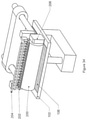
- FIG. 21 is a right perspective view of an imaging unit for use with a SFF device according to an embodiment of the presently disclosed subject matter.
- FIG. 22 is a right section view of the device in FIG. 21 .
- FIG. 23 is a left front perspective view of a layer deposition device for use in any embodiment of the presently disclosed subject matter.
- FIG. 24 is a left perspective view of the powder hopper of the device in FIG. 23 .
- FIG. 25 is a perspective view of the powder dispenser of the device in FIG. 23 .
- FIG. 26 is a left section view of the device in FIG. 23 .
- FIG. 27 is a left front perspective view of the device in FIG. 23 in a second position.
- FIG. 28 is a left section view of the device in FIG. 27 .
- FIG. 29 is a left front perspective view of the device in FIG. 23 in a third position.
- FIG. 30 is a left section view of the device in FIG. 29 .
- FIG. 31 is a perspective view of the powder sweeping and infusing blade of the device in FIG. 23 .
- FIG. 32 is a section view of the component in FIG. 31 .
- FIG. 33 is a left perspective view of a second embodiment of a layer deposition device for use in any embodiment of the presently disclosed subject matter.
- FIG. 34 is a left rear perspective view of the device in FIG. 33 .
- FIG. 35 is a rear section view of the device in FIG. 34 .
- FIG. 36 is a left perspective view of an embodiment of a material deposition device for use in any embodiment of the presently disclosed subject matter.
- FIG. 37 is a left section view of the device in FIG. 36 .
- FIG. 38 is a left perspective view of the device in FIG. 36 in a second position.
- FIG. 39 is a left section view of the device in FIG. 38 .
- FIG. 40 is a right perspective view of a second embodiment of a material deposition device for use in any embodiment of the presently disclosed subject matter.
- FIG. 41 is a right section view of the device in FIG. 40 .
- FIG. 42 is a right perspective view of the device in FIG. 40 in a second position.
- FIG. 43 is a right section view of the device in FIG. 42 .
- FIG. 44 is a right perspective view of an embodiment of a powder resupply device for use in any embodiment of the presently disclosed subject matter.
- FIG. 45 is a front perspective view of the device in FIG. 44 .
- FIG. 46 is a right top section view of the device in FIG. 44 .
- FIG. 47 is a left top section view of the device in FIG. 44 .
- FIG. 48 is a perspective view of an embodiment of a build platform for use in any embodiment of the presently disclosed subject matter.
- FIG. 49 is an exploded perspective view of the device in FIG. 48 .
- FIG. 50 is a perspective view of the sensor array of the device in FIG. 48 .
- FIG. 51 is a section view of the sensor array in FIG. 50 .
- FIG. 52 is a perspective view of a second embodiment of the build platform in FIG. 48 .
- FIG. 53 is a perspective view of a third embodiment of the build platform in FIG. 48 .
- FIG. 54 is an exploded perspective view of the build platform in FIG. 53 .
- FIG. 55 is a perspective view of a fourth embodiment of the build platform in FIG. 48 .
- FIG. 56 is an exploded perspective view of the device in FIG. 55 .
- FIG. 57 is a perspective view of a material containment vessel of the device in FIG. 55 .
- FIG. 58 is a perspective view of the device in FIG. 55 in a second position.
- FIG. 59 is a perspective view of a material containment vessel and build surface of the device in FIG. 58 .
- FIG. 60 is a perspective view of an object capable of being built by the presently disclosed subject matter.
- FIG. 61 is a perspective view of a possible support material arrangement for the object in FIG. 60 .
- FIG. 62 is a section view of the support material arrangement in FIG. 61 .
- FIG. 63 is an algorithmic flow chart for the production of a support material arrangement for use in the construction of an object by SFF according to an embodiment of the presently disclosed subject matter.
- FIG. 64 is an algorithmic flow chart for imaging layers of objects produced by the presently disclosed subject matter.
- FIG. 65 is an algorithmic flow chart for improving print speed in the presently disclosed subject matter.
- FIGS. 1-3 show an SFF device that builds on structures and processes in the prior art.
- This device consists of a build surface ( 102 ), a material deposition module ( 104 ), and an imaging unit ( 100 ).
- the material deposition module ( 104 ) deposits photocurable material ( 106 ) onto the build platform ( 102 ) where an image is created by the imaging unit ( 100 ).
- the imaging unit ( 100 ) can be used to cure the material ( 106 ) in a pattern representative of a layer of an object to be built (e.g., as represented in CAD data).
- the build platform ( 102 ) is moved to allow room for another layer to be created, and the process repeats until an object is built, layer by layer.
- the material layer ( 106 ) is curable by light, which solidifies the material to build the object. It is the object of the presently disclosed subject matter to improve each of these processes.
- FIGS. 4-6 depict a novel imaging arrangement and relevant components.
- Many current SFF devices utilize an imaging unit ( 100 ) comprising a programmable planar light source, such as a DLP projector ( 110 ), as shown in FIG. 6 , to cure the material layer ( 106 ).
- a programmable planar light source such as a DLP projector ( 110 )
- the advantage of this technique in contrast to methods that use a single laser, is that layers are cured in an imagewise fashion, which can improve build speed.
- part resolution can be limited in such a configuration by pixel resolution.
- the physical size of a pixel increases as the image size increases, as it does when larger objects are being created. This scaling of the pixel size can in some circumstances puts a significant constraint on the size of objects that can be printed at high resolution by a projector ( 110 ) alone.
- the SFF devices described herein can comprise a build surface ( 102 ) for production of a 3-dimensional solid component, a material delivery system configured to deposit one or more material layers ( 106 ) on the build surface ( 102 ), at least one of the material layers ( 106 ) being a photocurable material, a first imaging component (e.g., projector ( 110 )) having a first resolution, and a second imaging component (e.g., precision imaging device ( 120 )) having a second resolution that is different than the first resolution.
- a first imaging component e.g., projector ( 110 )
- a second imaging component e.g., precision imaging device ( 120 )
- the first imaging component and the second imaging component are operable individually and in combination together to selectively irradiate the photocurable material to at least partially solidify successive layers of the 3-dimensional solid component.
- a beam diameter of the second imaging component can be designed to be smaller than an equivalent beam diameter (e.g., pixel size) of the first imaging component (e.g., projector ( 110 )).
- the projector ( 110 ) is capable of quickly imaging the interior region of a cross section, while the precision imaging device ( 120 ) can rapidly image the border(s) of a cross section (i.e., the edges of the cross section that, when layered together, form the exterior surfaces of the component).
- the precision imaging device ( 120 ) can rapidly image the border(s) of a cross section (i.e., the edges of the cross section that, when layered together, form the exterior surfaces of the component).
- the precision imaging device ( 120 ) comprises of a collimated light source ( 122 ) that can be positioned to direct a beam of light ( 134 ) towards the build surface ( 102 ) (e.g., mounted in a bracket ( 124 ) above the build surface ( 102 )).
- the collimated light source ( 122 ) can comprise at least one laser, an LED collimated via one of a set of mirrors and/or lenses, or any of a variety of other such sources known in the art.
- the direction at which the beam of light ( 134 ) is directed towards the build surface can be selectively moved to enable detailed images to be generated.
- the beam of light ( 134 ) is reflected off of a primary mirror ( 126 ), which can be selectively movable to change the direction of the beam of light ( 134 ).
- the position of the primary mirror ( 126 ) can be selectively pivoted about a first axis (e.g., controlled by a rotary actuator ( 128 )) such that the beam of light ( 134 ) can be scanned in a first dimension across the build platform ( 102 ).
- the light beam ( 134 ) can further be reflected off of a secondary mirror ( 130 ) to further adjust the direction of the beam of light ( 134 ).
- the position of the secondary mirror ( 130 ) is selectively pivotable about a second axis (e.g., controlled by a second rotary actuator ( 132 )) such that the beam of light ( 134 ) can be scanned in a second dimension (e.g., substantially perpendicular to the first dimension) across the build platform ( 102 ).
- a second rotary actuator e.g., a second rotary actuator
- the position of the spot created by the beam of light ( 134 ) on the material layer ( 106 ) may be controlled such that a two-dimensional cross section is imaged.
- this precision imaging device ( 120 ) in tandem with a projector ( 110 ), the issues with respect to the resolution of a projector-based imaging system can be addressed by using the comparatively finer focus of the precision imaging device ( 120 ) to “smooth” the edges of the image irradiated by the projector ( 110 ).
- the precision of a given layer is determined by the positional precision of the precision imaging device ( 120 ), but the imaging time can be essentially the same as for a projector-based SFF device.
- FIGS. 7-9 depict an alternate embodiment of a device employing this technique.
- bulk imaging can be provided by an array of collimated radiation sources ( 140 ) that emits beams of radiation onto a primary mirror ( 142 ) controlled by a primary actuator ( 144 ). The beams are reflected onto a secondary mirror ( 148 ) controlled by a secondary actuator ( 146 ).
- the primary ( 142 ) and secondary ( 148 ) mirrors can be selectively moved to cause the beams to raster over the material layer ( 106 ) on the build surface ( 102 ).
- the direction at which the beams are aimed towards the build surface ( 102 ) is moved in a line-by-line scanning pattern over the material layer ( 106 ) such that the entire area to be irradiated is scanned progressively, one line at a time.
- the direction of the beams sweep across an entire width of the area to be irradiated in a first dimension (e.g., by rotating primary mirror ( 142 )), the beams are then advanced an incremental distance in a second dimension (e.g., by rotating secondary mirror ( 148 )), and the process is repeated in a line-by-line manner until the entire area to be irradiated is covered.
- Beams may be controllably switched on and off during the raster scan in a manner corresponding to the cross sectional image being formed by the device.
- detailed imaging is performed by two precision imaging modules ( 120 ), though in general there may be any other number of precision imaging modules.
- FIGS. 10-13 also depict a configuration employing the same concept of bulk imaging and precision imaging.
- bulk imaging is accomplished with an array of prism rastering modules ( 150 ).
- each prism rastering module ( 150 ) can comprise a source ( 154 ) configured to emit a beam ( 156 ) of collimated radiation.
- the beam ( 156 ) enters a rotating refractive material, such as a prism ( 158 ), and is refracted.
- a second refraction occurs, and the result is a displaced beam ( 160 ).
- the prism ( 158 ) has a substantially square section with a thickness exceeding a diameter of the beam ( 156 ).
- the prism ( 158 ) may in general be a polygon with an even number of faces. In some instances, opposing faces of the prism ( 158 ) may or may not be parallel, depending on the desired refraction and displacement behavior.
- each prism rastering module ( 150 ) is rotated by an actuator ( 162 ) which causes the displaced beam ( 160 ) to raster across the build surface ( 102 ).
- the prism rastering modules ( 150 ) can be mounted in a fixed relative position with respect to the build surface ( 102 ), and one or more mirrors, lenses, or other refractive material (e.g., a secondary mirror ( 148 ) as discussed above with respect to the embodiment of FIGS. 7-9 ) positioned between the prism ( 158 ) and the build surface ( 102 ) can be controlled to pan the direction at which the displaced beams ( 160 ) are aimed towards the build surface.
- a secondary mirror ( 148 ) positioned between the prism ( 158 ) and the build surface ( 102 ) can be controlled to pan the direction at which the displaced beams ( 160 ) are aimed towards the build surface.
- FIG. 14 shows a trace pattern, which can be imaged by an array of prism rastering modules ( 150 ) as discussed above.
- FIG. 15 shows the trace pattern ( 164 ) overlaid with a raster pattern ( 165 ) for a circular cross section ( 166 ).
- the sources ( 154 ) can be selectively activated such that the displaced beams ( 160 ) only irradiate the build surface ( 102 ) within the raster pattern ( 165 ). In this way, bulk imaging is restricted to the interior of the cross section ( 166 ) being imaged.
- an alternative raster pattern ( 168 ) that extends at least to the edge of the cross section ( 166 ) may be desirable depending on the properties of the radiation source ( 154 ) and/or the properties of the material layer being cured ( 106 ). If a particular radiation source is highly focused, and/or the material layer being cured has a low penetration depth coefficient, or the material tends to shrink during the curing process, this pattern (or one similar to it), which cures beyond the strict boundaries of the target cross sectional image, may be desirable.
- an overlapping raster pattern may be achieved, as in FIG. 17 .
- the lateral translation may be controlled such that the modules are translated a distance equivalent to the nominal diameter of the laser beam while the raster module rotates to produce one raster line.
- the radiation source ( 154 ) can be configured such that the resin to be irradiated would require two passes in order to be fully cured. In this way, the overlapping pattern may allow for resin to be partially cured in a first pass and fully cured in a second pass.
- a resolution finer than the width of a single rastered line may be achieved.
- FIGS. 18 and 19 depict an embodiment of the presently disclosed subject matter which utilizes prism raster modules ( 150 ) in an alternative orientation with respect to the build surface.
- material is not deposited on top of a build platform ( 102 ). Instead, the build platform ( 102 ) is lowered into a vat ( 170 ) of material. Radiation is emitted against the bottom ( 171 ) of the vat ( 170 ) which is generally transparent to the radiation being used. In this way, a layer of material is cured in a manner corresponding to a cross section of the object being built between the build platform ( 102 ) and the bottom ( 171 ) of the vat ( 170 ).
- the spacing between the build platform ( 102 ) and the bottom ( 171 ) of the vat ( 170 ) determines the layer thickness.
- resin contained within the vat ( 170 ) fills the void between the build object and the bottom ( 171 ) of the vat ( 170 ).
- each layer must be delaminated from the bottom surface of the vat ( 170 ) after curing, which typically involves moving the build platform ( 102 ) past where it will be located for the next layer (i.e., moving it a distance away from the bottom that is greater than the desired layer thickness), and then moving it back into position (i.e., distance from the bottom is substantially equal to the desired layer thickness) for the next layer.
- This movement acts as a layer formation process, but the delamination of the layer from the bottom surface and multi-step layer increment movement can put considerable stress on the object being built and requires a non-trivial amount of time.
- the layer is progressively delaminated while being built rather than delaminating an entire layer at once, which optimizes build speed and minimizes stress on the object being built.
- the spatial cure pattern achieved by such a process can be as shown in FIG. 20 .
- a section of the build surface ( 170 ) is shown with two layers of raster cure paths ( 172 , 174 ). It has been established that when a collimated source with Gaussian energy distribution is used to illuminate a photocurable substance, the cure volume is a parabolic prismatic shape, as shown here.
- the progressive delamination is represented in this example by the angle of the raster cure paths ( 172 , 174 ) with respect to the bottom surface of the vat ( 170 ) and by the fact that only a portion of one path of the lower set of raster paths ( 172 ) is in contact with the bottom surface of the vat ( 170 ). Even with this modified layer formation process, by switching the radiation source ( 154 ) on and off appropriately, an object can be built in a manner substantially similar to the methods discussed above.
- FIGS. 21 and 22 show an alternate embodiment of the prism raster module ( 150 ) previously described.
- the displaced beam of radiation ( 160 ) is reflected off of a stationary mirror ( 178 ) and onto a set of rotating mirrors ( 175 ) to scan the displaced beams ( 160 ) in a second dimension (e.g., different than the dimension across which the rotating prism ( 158 ) sweeps).
- the rotating mirrors ( 175 ) are controlled by an actuator ( 176 ).
- an actuator 176
- the rotating mirrors ( 175 ) are presented in an elongate octagonal configuration, although those having ordinary skill in the art will appreciate that, in general, they may be provided in any of a variety of elongate polygonal configurations (e.g., pentagonal, hexagonal). Regardless of the particular configuration of rotating mirrors ( 175 ), the reflected beam ( 177 ) in this apparatus will follow a predetermined trace pattern (e.g., the path described in FIG. 14 ) as long as the rotating mirrors ( 175 ) are rotated at an appropriate speed relative to the raster speed of the imaging unit ( 150 ).
- a predetermined trace pattern e.g., the path described in FIG. 14
- the rotating mirrors ( 175 ) may be actuated such that as the beam ( 160 ) is displaced by the rotating prism ( 158 ), the angular displacement of the exigent beam ( 177 ) during the tracing of one raster line is approximately equal to the nominal diameter of the exigent beam ( 177 ). This will produce sequential, non-overlapping raster lines.
- the angular speed of the rotating mirrors ( 175 ) may be adjusted if overlapping lines are desired for a particular application. As one facet of the rotating mirrors ( 175 ) rotates past the incident beam ( 160 ), it will move to the next facet, repeating the pattern for the next layer.
- the full raster trace pattern will be carried out automatically with continuous rotation of the optical units, which may be conducted at high speed with minimal vibration. This is advantageous when compared to traditional SLA imaging units, which require mirrors to move back and forth to raster an imaged area. Inertial and vibrational effects are limiting factors in traditional devices when optimizing imaging speed.
- the optical elements utilized to convert the linear rastering beam ( 160 ) of the imaging unit ( 150 ) into an area rastering pattern are a stationary mirror ( 178 ) and a set of rotating mirrors ( 175 ).
- the mirrors are flat.
- one or more of the stationary mirror ( 178 ) and/or the rotating mirrors ( 175 ) may be curved to produce different optical effects.
- the width of the raster path achieved at the build surface ( 102 ) will be wider than the width of the raster path traced by the beam ( 160 ) emitted by the imaging unit ( 150 ).
- the convexity and concavity of the mirrors used may be chosen to maintain beam collimation while producing this effect, and may also be chosen to reduce raster path width rather than increase it. Additionally, other optical elements, such as lenses, may be inserted at various points along the optical path to achieve a similar effect.
- the net result of combining a rotating prism apparatus imaging unit ( 150 ) for primary beam displacement and a rotating mirror set ( 175 ) for secondary beam displacement is a rapid rastering device for a particular target area.
- this may be achieved with any combination of prisms and rotating mirror sets (e.g., two rotating prisms, two rotating sets of mirrors, or a set of rotating mirrors may be used for primary beam displacement while a rotating prism is used for secondary beam displacement).
- the benefits of using constant velocity rotating optical elements will largely be the same regardless of configuration, though particular choices may be made to optimize the system for a particular application.
- the previously described imaging techniques may generally apply to any SFF device utilizing photocurable resin as a building material. They may also apply when so-called “hybrid resins” are used; this term is generally used to describe resins with particulate materials included in their composition. These resins typically contain dispersants which allow for particulate matter to remain suspended in the resin solution. The particle loading in these resins is limited in order to keep the viscosity of the suspension low enough to permit the creation of new layers of material in a SFF device; this particle loading can be a limiting feature in the hybrid resin's usability as a precursor for parts that will later be sintered.
- Collections of particles of either metallic or ceramic composition bound together with resin may be treated thermally and chemically to remove the binder and sinter the particulate matter together to form a solid part.
- conventional SLA techniques may be used to produce ceramic and metallic parts.
- the limitations of viscosity and shelf life pose challenges for the use of hybrid resins for advanced applications.
- the process of creating a layer of material from a mixture of photocurable resin and particulate material wherein the two materials remain separate until the layer creation process may be advantageous in many respects, given that it allows different combinations of particulate material and photocurable resin to be made without pre-mixing, and may circumvent rheological limitations in layer production, as will be described hereinbelow.
- FIGS. 23-32 depict apparati and components for the deposition of a composite layer of material for use in a SFF process.
- a powder hopper ( 180 ) is positioned above an edge of a build surface ( 102 ).
- the powder hopper ( 180 ) has a powder dispenser ( 182 ) with a powder dispensing groove ( 184 ), the powder dispenser ( 182 ) being rotatable such that the powder dispensing groove ( 184 ) is selectively in communication with either the powder hopper ( 180 ) or the build surface ( 102 ).
- the powder dispensing groove ( 184 ) is within the powder hopper ( 180 ), it can receive powder ( 186 ) therein.
- Powder dispenser ( 182 ) When the powder dispenser ( 182 ) rotates such that the powder dispensing groove ( 184 ) is facing towards the build platform ( 102 ), it can be configured to deposit a quantity of powder ( 188 ) onto the build platform ( 102 ).
- a powder leveling blade ( 190 ) may move across the build platform ( 102 ), producing a layer of powder.
- Powder leveling blade ( 190 ) can further include one or more resin input ports ( 192 ) that are configured to receive resin from a resin supply.
- the resin input ports ( 192 ) together or individually supply resin to a primary resin channel ( 194 ) interior to the blade portion of the powder leveling blade ( 190 ), and one or more resin infusion channels ( 196 ) branch from the primary resin channel ( 194 ) and terminate at the edge of the powder leveling blade ( 190 ) such that as the blade ( 190 ) levels the powder ( 188 ), resin may be pumped in and blended with the resin to form a material layer ( 106 ).
- the process of depositing powder may also be done independently of the resin infusion process.
- FIGS. 33-35 depict an alternative system for composite material layer production. As depicted, these figures presume the initial deposition of a layer of powder, but the order of material deposition may be arbitrary.
- the process of infusion, to create a material layer ( 106 ) involves pumping resin through a resin dispenser ( 204 ) containing many needles for dispensing resin into a diffusing material, such as a sponge ( 202 ).
- the diffused resin coats the outside of a roller ( 200 ) which rolls across a material layer ( 106 ), infusing it with resin.
- Rotation of the roller ( 200 ) is controlled by an actuator ( 206 ). Rotation of the roller ( 200 ) may be controlled such that tangential velocity is greater than, less than, or equal to translational velocity, in order to achieve desired infusion behavior.
- FIGS. 36-39 depict a system for powder deposition for creating a composite material layer.
- a powder hopper ( 210 ) contains powder ( 214 ) held back by a powder retainer ( 212 ). When the powder retainer ( 212 ) is raised, powder ( 214 ) may exit the aperture ( 216 ) of the powder hopper ( 210 ). The spacing between the powder hopper ( 210 ) and the build platform ( 102 ) will control the thickness of the material layer ( 106 ) created as the hopper ( 210 ) moves across the platform ( 102 ).
- FIGS. 40-43 depict another system for powder deposition for creating a composite material layer.
- a powder hopper ( 220 ) dispenses powder ( 232 ) onto a film ( 222 ) which passes around three rollers ( 224 , 226 , 228 ).
- the drive roller ( 228 ) is driven by an actuator ( 230 ) and causes the film ( 222 ) to move and actuate the other rollers ( 224 , 226 ).
- the primary layer roller ( 224 ) transfers powder ( 232 ) from the powder hopper ( 220 ) to the build surface ( 102 ).
- the secondary powder roller ( 226 ) controls the film ( 222 ) position relative to the build platform ( 102 ) and can apply added compression to the material layer ( 106 ).
- the powder hopper ( 220 ) may be resupplied from an external source, which may also apply an electrical charge to the powder, as in a powder coating gun. Standard industrial techniques exist for applying a static charge to powder; in this apparatus, the primary layer roller ( 224 ) may be grounded, and the applied electric charge may cause powder to cling to the film ( 222 ) as it is dispensed from the hopper ( 220 ), which may aid in maintaining consistency when dispensing material layers ( 106 ).
- FIGS. 44-47 depict a powder resupply unit ( 240 ).
- the aforementioned powder hopper ( 220 ) or any other powder dispensing device previously described may be resupplied with powder from this unit ( 240 ) which may be located away from the build area ( 102 ).
- the powder resupply unit ( 240 ) has an exit port ( 244 ) from which aerated powder will flow and which can be connected to any vessel requiring a supply of powder.
- Air, or other gas is pumped into the aerator inlet ( 242 ) and enters the unit ( 240 ) through four aeration tubes ( 248 , 250 , 252 , 254 ).
- FIGS. 48-51 depict one embodiment of such a system.
- the modified build platform ( 262 ) has a removable build surface ( 260 ). Underneath the removable build surface ( 260 ) there is an array of sensor modules ( 264 ) which provide feedback to calibrate multiple imaging devices. Each sensor module ( 264 ) contains a shrouded sensor ( 266 ); the shroud may improve the precision of the feedback system.
- FIG. 52 depicts a second embodiment of a calibration feedback system.
- a sensor module ( 280 ) of a similar configuration to the previous sensor modules ( 264 ) is movable by a screw ( 276 ) controlled by an actuator ( 278 ) along a primary axis of motion.
- the entire primary axis assembly is movable by a secondary screw ( 274 ) controlled by a secondary actuator ( 272 ) along a secondary axis of motion.
- the sensor module ( 280 ) may be moved to any point within the build area for a calibration process.
- Either of the modified build platforms ( 262 , 270 ) may have the build surface ( 260 ) removed for calibration, at which point the build platforms ( 262 , 270 ) may move into a position such that their sensor surfaces are in the same position as the initial position of the face of the build surface ( 260 ) that is used for building an object during a build process.
- sensor readings are an accurate reading of actual illumination patterns at an appropriate print position used during a build process.
- a removable build surface ( 260 ) can provide the advantage of allowing for a built in calibration system that assists in coordinating multiple imaging devices within an SFF device. While many SFF devices have removable build platforms, build trays, and other objects for containing a built part after the build process is completed, these all have proprietary, often complex designs. It may be advantageous to allow any substantially flat piece of rigid material to be a removable build surface ( 260 ), by decreasing the cost of replacement and simplifying the process of using such a surface. Accordingly, FIGS. 53 and 54 depict one embodiment of a build platform ( 300 ) with removable build surface ( 260 ).
- This removable build surface ( 260 ) may be held in place during a build process by attachment points ( 302 , 304 , 306 , 308 ) which may contain magnets, or may be ports capable of applying a vacuum to retain the removable build surface ( 260 ).
- the attachment points ( 302 , 304 , 306 , 308 ) may be any mechanism designed to apply a force to a substantially flat, substantially uniform removable build surface ( 260 ).
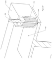
- FIGS. 55-59 depict an alternate embodiment of a build platform ( 320 ) with removable build surface ( 260 ) which achieves this effect.
- This modified build platform ( 320 ) contains attachment points ( 302 , 304 , 306 , 308 ) as before, and also has indentations at its corners ( 322 , 324 , 326 , 328 ).
- the indentations ( 322 , 324 , 326 , 328 ) move past protrusions ( 312 , 314 , 316 , 318 ) in a material containment vessel ( 310 ).
- the material containment vessel ( 310 ) thus engages the build surface ( 260 ) such that they can be moved together, while keeping the build object and any unused build material contained for later cleaning and other post-processing.
- Support material is often used during SFF processes. Support material helps an object withstand forces from the application of new layers of material, and stabilizes certain part geometry such as overhanging features. Support material must be removed before an object is complete, which is often done in post-processing.
- a common technique for creating support material is to have large buttress-like support structures connected to an object at a plurality of small connection points to facilitate removal of the support material by breaking it at these connection points. These connection points must be sanded or otherwise finished to produce a smooth final object; any added finishing due to support material slows production time for parts produced by SFF, and it is therefore desirable that the effect of support material on surface finish be reduced.
- FIG. 60 depicts an object ( 330 ) to be built on a build surface ( 102 ).
- FIGS. 61 and 62 depict a possible support material arrangement for this object during the build process.
- Objects that are fabricated from a mixture of power and resin may have support material ( 332 ) that is shaped to take advantage of the semi-solid nature of this uncured material. The presence of powder in the uncured material gives it greater inherent resistance to the forces applied by the production of new layers of material.
- Support material ( 332 ) may be shaped such that it envelopes portions of an object ( 330 ) requiring stabilization without being in direct contact with the object ( 330 ).
- the support technique described above may be depicted algorithmically as in FIG. 63 . Rather than determining overhanging regions or other fragile regions requiring support, as in buttress support techniques, this process requires analyzing a model for surfaces that face in the direction of the shear force applied when a new layer of material is produced. Based on the fragility of a given region, connection points may or may not be used. Tool paths generated for the support structure will be merged with those for the build object such that they can be built concurrently within a given layer.
- Border regions are here defined as the edge, or region representative of an edge, or region to be imaged which will serve as a boundary of an imaged region.
- Interior regions are here defined as regions to be imaged which are substantially confined within border regions. Interior regions generally do not require as high resolution as border regions. The precision of a built object as a whole is generally defined by the resolution of the border regions of its layers. As shown in FIG. 64 , the standard process of slicing CAD data into layers may be further extended by differentiating between interior data and border data. Border data may substantially be stored as vector data, where the precise curvilinear nature of the border region may be preserved.
- Interior data may be substantially stored in a bitmap format, which does not preserve curvature but does allow for rapid data processing for an imaging device.
- the imaging of interior data may be undertaken by a variety of devices, such as those described above.
- Border data may be imaged by a collimated radiation beam source wherein radiation is directed along the border region in such a manner to preserve the precise curvilinear structure of the border region.
- Standard SFF file types often reduce the representation of an object to a collection of polygons; during this process, curvature information is reduced to a representation by many small segments. The user is left with the choice to either create a very large file to preserve detail, or save on file space and subsequent processing time by a SFF device by sacrificing precision.
- FIG. 65 represents a process by which layer production may be expedited, which applies to both inverted and standard SFF devices as described above.
- the process of layer production is limited by the viscosity of the resin being used; this is especially true with composite resin mixtures. Viscosity may be reduced by the introduction of solvents or other chemical agents, or by increasing the temperature of the resin material. In some cases, such as in the addition of chemical agents, it may be desirable to allow said agents to evaporate after a layer has been produced in order to normalize the fluid viscosity and stabilize the material layer. In some other instances, such as when the entire build chamber is at an elevated temperature, viscosity will not be normalized during the build, and in fact temperature will be maintained at an elevated level until the completion of a build process. This method generally improves the speed of a build process in multiple embodiments of the presently disclosed subject matter.
Landscapes
- Engineering & Computer Science (AREA)
- Chemical & Material Sciences (AREA)
- Materials Engineering (AREA)
- Manufacturing & Machinery (AREA)
- Physics & Mathematics (AREA)
- Optics & Photonics (AREA)
- Mechanical Engineering (AREA)
- Health & Medical Sciences (AREA)
- Toxicology (AREA)
- General Physics & Mathematics (AREA)
- Microelectronics & Electronic Packaging (AREA)
- Producing Shaped Articles From Materials (AREA)
- Powder Metallurgy (AREA)
Abstract
Description
Claims (13)
Priority Applications (1)
| Application Number | Priority Date | Filing Date | Title |
|---|---|---|---|
| US15/568,738 US11241827B2 (en) | 2015-04-07 | 2016-04-07 | Method and apparatus for solid freeform fabrication of objects with improved resolution |
Applications Claiming Priority (3)
| Application Number | Priority Date | Filing Date | Title |
|---|---|---|---|
| US201562144016P | 2015-04-07 | 2015-04-07 | |
| PCT/US2016/026510 WO2016164629A1 (en) | 2015-04-07 | 2016-04-07 | Method and apparatus for solid freeform fabrication of objects with improved resolution background |
| US15/568,738 US11241827B2 (en) | 2015-04-07 | 2016-04-07 | Method and apparatus for solid freeform fabrication of objects with improved resolution |
Publications (2)
| Publication Number | Publication Date |
|---|---|
| US20180141270A1 US20180141270A1 (en) | 2018-05-24 |
| US11241827B2 true US11241827B2 (en) | 2022-02-08 |
Family
ID=57072861
Family Applications (1)
| Application Number | Title | Priority Date | Filing Date |
|---|---|---|---|
| US15/568,738 Active 2036-08-29 US11241827B2 (en) | 2015-04-07 | 2016-04-07 | Method and apparatus for solid freeform fabrication of objects with improved resolution |
Country Status (11)
| Country | Link |
|---|---|
| US (1) | US11241827B2 (en) |
| EP (1) | EP3280579A4 (en) |
| JP (2) | JP2018518400A (en) |
| KR (1) | KR20170133506A (en) |
| CN (1) | CN107614229A (en) |
| BR (1) | BR112017021657A2 (en) |
| CA (1) | CA2982127A1 (en) |
| IL (1) | IL254905A0 (en) |
| MX (1) | MX2017012788A (en) |
| SG (2) | SG11201708252WA (en) |
| WO (1) | WO2016164629A1 (en) |
Families Citing this family (22)
| Publication number | Priority date | Publication date | Assignee | Title |
|---|---|---|---|---|
| SG11201708252WA (en) | 2015-04-07 | 2017-11-29 | Trio Labs Inc | Method and apparatus for solid freeform fabrication of objects with improved resolution background |
| DE102016104180A1 (en) | 2016-03-08 | 2017-09-14 | Cl Schutzrechtsverwaltungs Gmbh | Device for the additive production of a three-dimensional object |
| CN106738867B (en) * | 2017-01-10 | 2019-09-13 | 北京大学 | A broadband piezoelectric vibration scraper and its spraying 3D printing and printing method |
| CN108927993B (en) * | 2017-05-26 | 2020-12-15 | 三纬国际立体列印科技股份有限公司 | Light curing 3D printing method of multi-light source module |
| JP2020529936A (en) * | 2017-08-02 | 2020-10-15 | トリオ ラブズ インコーポレイテッドTrio Labs, Inc. | 3D free modeling using in situ injection and imaging |
| US20190129308A1 (en) | 2017-11-02 | 2019-05-02 | Taiwan Green Point Enterprises Co., Ltd. | Digital masking system, pattern imaging apparatus and digital masking method |
| US11518100B2 (en) | 2018-05-09 | 2022-12-06 | Applied Materials, Inc. | Additive manufacturing with a polygon scanner |
| US20190351484A1 (en) * | 2018-05-20 | 2019-11-21 | 3D Flexible, Inc. | Metal pastes for additive manufacturing |
| CN110711040B (en) * | 2018-07-13 | 2021-10-15 | 法蓝瓷股份有限公司 | Method for manufacturing ceramic teeth by three-dimensional lamination |
| TWI673250B (en) * | 2018-07-13 | 2019-10-01 | 法藍瓷股份有限公司 | Water-based ceramic three-dimensional laminated material and method for manufacturing ceramic parts using the same |
| US10759116B2 (en) * | 2018-09-14 | 2020-09-01 | Intrepid Automation | Additive manufactured parts with smooth surface finishes |
| CN109878077A (en) * | 2019-02-26 | 2019-06-14 | 湖南华曙高科技有限责任公司 | Increasing material manufacturing equipment and increasing material manufacturing method |
| GB201902883D0 (en) * | 2019-03-04 | 2019-04-17 | Photocentric Ltd | Method of making 3D printed objects by dispensing sequential layers of material |
| WO2020185553A1 (en) * | 2019-03-12 | 2020-09-17 | Trio Labs, Inc | Method and apparatus for digital fabrication of objects using actuated micropixelation and dynamic density control |
| EP3726293A1 (en) * | 2019-04-19 | 2020-10-21 | Universiteit van Amsterdam | Stereo lithographic 3d printing assembly and stereo lithographic3d printing method |
| CN116096553A (en) * | 2020-08-21 | 2023-05-09 | 3M创新有限公司 | Method for manufacturing physical object and 3D printing system |
| JP7803054B2 (en) * | 2021-07-28 | 2026-01-21 | セイコーエプソン株式会社 | Modeling stage and three-dimensional modeling device |
| US20250296283A1 (en) * | 2022-05-13 | 2025-09-25 | University Of Southern California | Hopping light additive manufacturing |
| CN114986871B (en) * | 2022-05-24 | 2024-03-15 | 东莞理工学院 | A device for photothermal multifunctional synergy to assist fine direct writing printing |
| US20240059011A1 (en) * | 2022-08-18 | 2024-02-22 | General Electric Company | Systems and methods for additive manufacturing using pixel shifting |
| US20240059013A1 (en) * | 2022-08-18 | 2024-02-22 | General Electric Company | Systems and methods for additive manufacturing using pixel shifting |
| US20240059022A1 (en) * | 2022-08-18 | 2024-02-22 | General Electric Company | Systems and methods for additive manufacturing using pixel shifting |
Citations (43)
| Publication number | Priority date | Publication date | Assignee | Title |
|---|---|---|---|---|
| US4844144A (en) | 1988-08-08 | 1989-07-04 | Desoto, Inc. | Investment casting utilizing patterns produced by stereolithography |
| EP0354637A2 (en) | 1988-04-18 | 1990-02-14 | 3D Systems, Inc. | CAD/CAM stereolithographic data conversion |
| US4938816A (en) | 1986-10-17 | 1990-07-03 | Board Of Regents, The University Of Texas System | Selective laser sintering with assisted powder handling |
| US5121329A (en) | 1989-10-30 | 1992-06-09 | Stratasys, Inc. | Apparatus and method for creating three-dimensional objects |
| US5184307A (en) | 1988-04-18 | 1993-02-02 | 3D Systems, Inc. | Method and apparatus for production of high resolution three-dimensional objects by stereolithography |
| US5204055A (en) * | 1989-12-08 | 1993-04-20 | Massachusetts Institute Of Technology | Three-dimensional printing techniques |
| US5238614A (en) * | 1991-05-28 | 1993-08-24 | Matsushita Electric Words, Ltd., Japan | Process of fabricating three-dimensional objects from a light curable resin liquid |
| US5262887A (en) | 1992-11-12 | 1993-11-16 | Xerox Corporation | Raster output scanner architecture employing rotating prism facet tracking |
| US5352405A (en) | 1992-12-18 | 1994-10-04 | Dtm Corporation | Thermal control of selective laser sintering via control of the laser scan |
| US5503785A (en) | 1994-06-02 | 1996-04-02 | Stratasys, Inc. | Process of support removal for fused deposition modeling |
| US5626919A (en) * | 1990-03-01 | 1997-05-06 | E. I. Du Pont De Nemours And Company | Solid imaging apparatus and method with coating station |
| WO1998006560A1 (en) | 1996-08-08 | 1998-02-19 | Sri International | Apparatus for automated fabrication of three-dimensional objects, and associated methods of use |
| WO1998041944A1 (en) | 1997-03-19 | 1998-09-24 | Replicator Systems, Inc. | Apparatus and method for production of three-dimensional models by spatial light modulator |
| US5900207A (en) | 1996-02-08 | 1999-05-04 | Rutgers, The State University Old Queens | Solid freeform fabrication methods |
| US5923359A (en) | 1997-03-14 | 1999-07-13 | Cymbolic Sciences International Inc. | Internal drum scophony raster recording device |
| DE19853834A1 (en) * | 1998-11-21 | 2000-05-31 | Ingo Ederer | Production of casting molds comprises depositing particulate material on support, applying binder and hardener to form solidified structure in selected region, and removing solidified structure |
| US6117612A (en) | 1995-04-24 | 2000-09-12 | Regents Of The University Of Michigan | Stereolithography resin for rapid prototyping of ceramics and metals |
| US6238614B1 (en) | 1998-08-13 | 2001-05-29 | Korea Advanced Institute Science And Technology | Selective infiltration manufacturing method and apparatus to fabricate prototypes and moulds by infiltrating molten droplets selectively into layers of powder |
| US20010050448A1 (en) * | 2000-05-24 | 2001-12-13 | Minolta Co., Ltd. | Three-dimensional modeling apparatus |
| US20020020945A1 (en) * | 2000-08-18 | 2002-02-21 | Uichung Cho | Forming three dimensional objects through bulk heating of layers with differential material properties |
| US20020093115A1 (en) | 2001-01-12 | 2002-07-18 | Jang B. Z. | Layer manufacturing method and apparatus using a programmable planar light source |
| US20020149137A1 (en) | 2001-04-12 | 2002-10-17 | Bor Zeng Jang | Layer manufacturing method and apparatus using full-area curing |
| US6596224B1 (en) * | 1996-05-24 | 2003-07-22 | Massachusetts Institute Of Technology | Jetting layers of powder and the formation of fine powder beds thereby |
| US20030173713A1 (en) * | 2001-12-10 | 2003-09-18 | Wen-Chiang Huang | Maskless stereo lithography method and apparatus for freeform fabrication of 3-D objects |
| US20050079086A1 (en) | 2003-10-14 | 2005-04-14 | Isaac Farr | System and method for fabricating a three-dimensional metal object using solid free-form fabrication |
| US20050263934A1 (en) * | 2004-05-28 | 2005-12-01 | 3D Systems, Inc. | Single side feed parked powder wave heating with wave flattener |
| US7120512B2 (en) * | 2003-08-25 | 2006-10-10 | Hewlett-Packard Development Company, L.P. | Method and a system for solid freeform fabricating using non-reactive powder |
| CN101024307A (en) * | 2007-01-19 | 2007-08-29 | 中国科学院广州电子技术研究所 | Resin liquid-level control for photo-solidification quick formation and resin coating method and apparatus |
| US20090148813A1 (en) | 2007-08-31 | 2009-06-11 | Sun Benjamin J | Three-dimensional printing methods and materials for making dental products |
| US20100125356A1 (en) * | 2008-11-18 | 2010-05-20 | Global Filtration Systems | System and Method for Manufacturing |
| US7758329B2 (en) | 2006-12-28 | 2010-07-20 | Sony Corporation | Optical modeling apparatus |
| US8094355B2 (en) | 2009-04-29 | 2012-01-10 | Corning Incorporated | Laser projection system with a spinning polygon for speckle mitigation |
| WO2012140658A2 (en) | 2011-04-10 | 2012-10-18 | Objet Ltd. | System and method for layer by layer printing of an object with support |
| US20130329257A1 (en) | 2012-06-08 | 2013-12-12 | Makerbot Industries, Llc | Downloadable three-dimensional models |
| US20140154629A1 (en) | 2012-11-30 | 2014-06-05 | Canon Kabushiki Kaisha | Lithography apparatus and method of manufacturing article |
| US20140255666A1 (en) | 2013-03-06 | 2014-09-11 | University Of Louisville Research Foundation, Inc. | Powder Bed Fusion Systems, Apparatus, and Processes for Multi-Material Part Production |
| US20150190965A1 (en) * | 2014-01-09 | 2015-07-09 | Seiko Epson Corporation | Three-dimensional shaped article manufacturing method, three-dimensional shaped article manufacturing apparatus, ink set, and three-dimensional shaped article |
| US20150273766A1 (en) * | 2014-03-27 | 2015-10-01 | Seiko Epson Corporation | Method for producing object |
| US20150343760A1 (en) * | 2014-05-30 | 2015-12-03 | The Procter & Gamble Company | Method for making a customizable apparatus for transporting and depositing fluids |
| US20160325496A1 (en) * | 2014-01-16 | 2016-11-10 | Hewlett-Packard Development Company, L.P. | Generating three-dimensional objects |
| US9566601B2 (en) * | 2012-04-25 | 2017-02-14 | Dieffenbacher GmbH Maschinen- und Anlangenbau | Method and doctor blade device for spreading a resin paste onto a carrier film, and a resin sheet installation for producing resin sheets |
| CN107614229A (en) | 2015-04-07 | 2018-01-19 | 特里奥实验室公司 | The method and apparatus for carrying out solid freeform manufacture to object with improved resolution ratio background |
| US10695954B2 (en) * | 2014-08-29 | 2020-06-30 | Exone Gmbh | Coater arrangement for a 3D printer and method for applying two layers of particle-shaped construction material |
Family Cites Families (1)
| Publication number | Priority date | Publication date | Assignee | Title |
|---|---|---|---|---|
| AU4971396A (en) * | 1995-02-01 | 1996-08-21 | 3D Systems, Inc. | Rapid recoating of three-dimensional objects formed on a cross-sectional basis |
-
2016
- 2016-04-07 SG SG11201708252WA patent/SG11201708252WA/en unknown
- 2016-04-07 CN CN201680026682.0A patent/CN107614229A/en active Pending
- 2016-04-07 BR BR112017021657A patent/BR112017021657A2/en active Search and Examination
- 2016-04-07 CA CA2982127A patent/CA2982127A1/en not_active Abandoned
- 2016-04-07 US US15/568,738 patent/US11241827B2/en active Active
- 2016-04-07 EP EP16777308.4A patent/EP3280579A4/en not_active Withdrawn
- 2016-04-07 JP JP2018503738A patent/JP2018518400A/en active Pending
- 2016-04-07 KR KR1020177032152A patent/KR20170133506A/en not_active Withdrawn
- 2016-04-07 MX MX2017012788A patent/MX2017012788A/en unknown
- 2016-04-07 SG SG10201909321X patent/SG10201909321XA/en unknown
- 2016-04-07 WO PCT/US2016/026510 patent/WO2016164629A1/en not_active Ceased
-
2017
- 2017-10-06 IL IL254905A patent/IL254905A0/en unknown
-
2021
- 2021-03-09 JP JP2021037628A patent/JP2021107150A/en active Pending
Patent Citations (46)
| Publication number | Priority date | Publication date | Assignee | Title |
|---|---|---|---|---|
| US4938816A (en) | 1986-10-17 | 1990-07-03 | Board Of Regents, The University Of Texas System | Selective laser sintering with assisted powder handling |
| EP0354637A2 (en) | 1988-04-18 | 1990-02-14 | 3D Systems, Inc. | CAD/CAM stereolithographic data conversion |
| US5184307A (en) | 1988-04-18 | 1993-02-02 | 3D Systems, Inc. | Method and apparatus for production of high resolution three-dimensional objects by stereolithography |
| US4844144A (en) | 1988-08-08 | 1989-07-04 | Desoto, Inc. | Investment casting utilizing patterns produced by stereolithography |
| US5121329A (en) | 1989-10-30 | 1992-06-09 | Stratasys, Inc. | Apparatus and method for creating three-dimensional objects |
| US5807437A (en) * | 1989-12-08 | 1998-09-15 | Massachusetts Institute Of Technology | Three dimensional printing system |
| US5204055A (en) * | 1989-12-08 | 1993-04-20 | Massachusetts Institute Of Technology | Three-dimensional printing techniques |
| US5626919A (en) * | 1990-03-01 | 1997-05-06 | E. I. Du Pont De Nemours And Company | Solid imaging apparatus and method with coating station |
| US5238614A (en) * | 1991-05-28 | 1993-08-24 | Matsushita Electric Words, Ltd., Japan | Process of fabricating three-dimensional objects from a light curable resin liquid |
| US5262887A (en) | 1992-11-12 | 1993-11-16 | Xerox Corporation | Raster output scanner architecture employing rotating prism facet tracking |
| US5352405A (en) | 1992-12-18 | 1994-10-04 | Dtm Corporation | Thermal control of selective laser sintering via control of the laser scan |
| US5503785A (en) | 1994-06-02 | 1996-04-02 | Stratasys, Inc. | Process of support removal for fused deposition modeling |
| US6117612A (en) | 1995-04-24 | 2000-09-12 | Regents Of The University Of Michigan | Stereolithography resin for rapid prototyping of ceramics and metals |
| US5900207A (en) | 1996-02-08 | 1999-05-04 | Rutgers, The State University Old Queens | Solid freeform fabrication methods |
| US6596224B1 (en) * | 1996-05-24 | 2003-07-22 | Massachusetts Institute Of Technology | Jetting layers of powder and the formation of fine powder beds thereby |
| WO1998006560A1 (en) | 1996-08-08 | 1998-02-19 | Sri International | Apparatus for automated fabrication of three-dimensional objects, and associated methods of use |
| US5923359A (en) | 1997-03-14 | 1999-07-13 | Cymbolic Sciences International Inc. | Internal drum scophony raster recording device |
| WO1998041944A1 (en) | 1997-03-19 | 1998-09-24 | Replicator Systems, Inc. | Apparatus and method for production of three-dimensional models by spatial light modulator |
| US6238614B1 (en) | 1998-08-13 | 2001-05-29 | Korea Advanced Institute Science And Technology | Selective infiltration manufacturing method and apparatus to fabricate prototypes and moulds by infiltrating molten droplets selectively into layers of powder |
| DE19853834A1 (en) * | 1998-11-21 | 2000-05-31 | Ingo Ederer | Production of casting molds comprises depositing particulate material on support, applying binder and hardener to form solidified structure in selected region, and removing solidified structure |
| US20010050448A1 (en) * | 2000-05-24 | 2001-12-13 | Minolta Co., Ltd. | Three-dimensional modeling apparatus |
| US20020020945A1 (en) * | 2000-08-18 | 2002-02-21 | Uichung Cho | Forming three dimensional objects through bulk heating of layers with differential material properties |
| US20020093115A1 (en) | 2001-01-12 | 2002-07-18 | Jang B. Z. | Layer manufacturing method and apparatus using a programmable planar light source |
| US20020149137A1 (en) | 2001-04-12 | 2002-10-17 | Bor Zeng Jang | Layer manufacturing method and apparatus using full-area curing |
| US20030173713A1 (en) * | 2001-12-10 | 2003-09-18 | Wen-Chiang Huang | Maskless stereo lithography method and apparatus for freeform fabrication of 3-D objects |
| US7120512B2 (en) * | 2003-08-25 | 2006-10-10 | Hewlett-Packard Development Company, L.P. | Method and a system for solid freeform fabricating using non-reactive powder |
| US20050079086A1 (en) | 2003-10-14 | 2005-04-14 | Isaac Farr | System and method for fabricating a three-dimensional metal object using solid free-form fabrication |
| JP2005120475A (en) | 2003-10-14 | 2005-05-12 | Hewlett-Packard Development Co Lp | Apparatus and method for manufacturing three-dimensional metallic object |
| US20050263934A1 (en) * | 2004-05-28 | 2005-12-01 | 3D Systems, Inc. | Single side feed parked powder wave heating with wave flattener |
| US7758329B2 (en) | 2006-12-28 | 2010-07-20 | Sony Corporation | Optical modeling apparatus |
| CN101024307A (en) * | 2007-01-19 | 2007-08-29 | 中国科学院广州电子技术研究所 | Resin liquid-level control for photo-solidification quick formation and resin coating method and apparatus |
| US20090148813A1 (en) | 2007-08-31 | 2009-06-11 | Sun Benjamin J | Three-dimensional printing methods and materials for making dental products |
| US20100125356A1 (en) * | 2008-11-18 | 2010-05-20 | Global Filtration Systems | System and Method for Manufacturing |
| US8094355B2 (en) | 2009-04-29 | 2012-01-10 | Corning Incorporated | Laser projection system with a spinning polygon for speckle mitigation |
| WO2012140658A2 (en) | 2011-04-10 | 2012-10-18 | Objet Ltd. | System and method for layer by layer printing of an object with support |
| US9566601B2 (en) * | 2012-04-25 | 2017-02-14 | Dieffenbacher GmbH Maschinen- und Anlangenbau | Method and doctor blade device for spreading a resin paste onto a carrier film, and a resin sheet installation for producing resin sheets |
| US20130329257A1 (en) | 2012-06-08 | 2013-12-12 | Makerbot Industries, Llc | Downloadable three-dimensional models |
| US20140154629A1 (en) | 2012-11-30 | 2014-06-05 | Canon Kabushiki Kaisha | Lithography apparatus and method of manufacturing article |
| US20140255666A1 (en) | 2013-03-06 | 2014-09-11 | University Of Louisville Research Foundation, Inc. | Powder Bed Fusion Systems, Apparatus, and Processes for Multi-Material Part Production |
| US20150190965A1 (en) * | 2014-01-09 | 2015-07-09 | Seiko Epson Corporation | Three-dimensional shaped article manufacturing method, three-dimensional shaped article manufacturing apparatus, ink set, and three-dimensional shaped article |
| US20160325496A1 (en) * | 2014-01-16 | 2016-11-10 | Hewlett-Packard Development Company, L.P. | Generating three-dimensional objects |
| US20150273766A1 (en) * | 2014-03-27 | 2015-10-01 | Seiko Epson Corporation | Method for producing object |
| US20150343760A1 (en) * | 2014-05-30 | 2015-12-03 | The Procter & Gamble Company | Method for making a customizable apparatus for transporting and depositing fluids |
| US10695954B2 (en) * | 2014-08-29 | 2020-06-30 | Exone Gmbh | Coater arrangement for a 3D printer and method for applying two layers of particle-shaped construction material |
| CN107614229A (en) | 2015-04-07 | 2018-01-19 | 特里奥实验室公司 | The method and apparatus for carrying out solid freeform manufacture to object with improved resolution ratio background |
| EP3280579A1 (en) | 2015-04-07 | 2018-02-14 | Trio Labs, Inc. | Method and apparatus for solid freeform fabrication of objects with improved resolution background |
Non-Patent Citations (16)
| Title |
|---|
| "Hybrid Film Applicator: Doctor Blade (100mm) + Slot Die (50mm) Heads—EQ-HDS-100." MTI Corp—Leading Provider of Lab Equipments and Advanced Crystal Substrates, Sep. 19, 2012, www.mtixtl.com/EQ-HDS-100.aspx. (Year: 2012). * |
| Brazilian Office Action for Application No. BR112017021657-4 dated Feb. 10, 2020. |
| Chinese Office Action for Application No. 201680026682.0 dated Sep. 17, 2019. |
| CN101024307 (Zhao) Jan. 2007 (online machine translation), [Retrieved on Dec. 3, 2019]. Retrieved from: Espacenet (Year: 2007). * |
| DE19853834 (Kudernatsch) Nov. 1998 (online machine translation), [Retrieved on May 3, 2021]. Retrieved from: Espacenet (Year: 1998). * |
| EP, Communication pursuant to Article 94(3) EPC, Application No. 16 777 308.4, dated Mar. 19, 2021. |
| European Office Action for Application No. 16777308.4 dated Feb. 3, 2020. |
| Extended European Search Report for Application No. 16777308.4 dated Nov. 19, 2018. |
| First Chinese Office Action for Application No. 201680026682.0 dated Feb. 1, 2019. |
| IN, Examination Report, Application No. 201717038913, dated Mar. 20, 2020. |
| IPRP with International Search Report and Written Opinion for Application No. PCT/US2016/026510 dated Oct. 10, 2017. |
| JP, Office Action, Application No. 2018-503738, dated Apr. 21, 2020. |
| Notice of Publication for CN Application No. 201680026682.0 dated Jan. 31, 2018. |
| Notice of Publication for EP Application No. 16777308.4dated Jan. 1, 2017. |
| Vietnamese Office Action for Application No. 1-2017-04412 dated Jan. 13, 2018. |
| VN, Substantive Examination Results, Application No. 1-2017-04412, dated Jul. 30, 2021. |
Also Published As
| Publication number | Publication date |
|---|---|
| SG11201708252WA (en) | 2017-11-29 |
| IL254905A0 (en) | 2017-12-31 |
| KR20170133506A (en) | 2017-12-05 |
| CN107614229A (en) | 2018-01-19 |
| EP3280579A4 (en) | 2018-12-19 |
| JP2018518400A (en) | 2018-07-12 |
| EP3280579A1 (en) | 2018-02-14 |
| WO2016164629A1 (en) | 2016-10-13 |
| MX2017012788A (en) | 2018-02-09 |
| BR112017021657A2 (en) | 2018-07-10 |
| JP2021107150A (en) | 2021-07-29 |
| US20180141270A1 (en) | 2018-05-24 |
| CA2982127A1 (en) | 2016-10-13 |
| SG10201909321XA (en) | 2019-11-28 |
Similar Documents
| Publication | Publication Date | Title |
|---|---|---|
| US11241827B2 (en) | Method and apparatus for solid freeform fabrication of objects with improved resolution | |
| JP6983792B2 (en) | Solid modeling methods and equipment to which in-situ injection is applied | |
| US10717265B2 (en) | Array of printhead modules for additive manufacturing system | |
| US10882111B2 (en) | Apparatus for fusing of multiple layers in additive manufacturing | |
| US12083738B2 (en) | Method, device, and recoating module for producing a three-dimensional object | |
| KR102244986B1 (en) | 3d printing using spiral buildup | |
| US10596763B2 (en) | Additive manufacturing with array of energy sources | |
| US20220048251A1 (en) | 3d printer | |
| US20210183287A1 (en) | Solid freeform fabrication utilizing in situ infusion and imaging | |
| US20230373158A1 (en) | Method and apparatus for digital fabrication and structure made using the same | |
| US20230173753A1 (en) | Leveling system for three-dimensional printing | |
| CN109982830B (en) | Information processing apparatus, forming device, information processing method, and program | |
| US20260008234A1 (en) | Method and system for manipulating curing radiation in three-dimensional printing | |
| EP4225521A1 (en) | Method and apparatus for digital fabrication and structure made using the same |
Legal Events
| Date | Code | Title | Description |
|---|---|---|---|
| FEPP | Fee payment procedure |
Free format text: ENTITY STATUS SET TO UNDISCOUNTED (ORIGINAL EVENT CODE: BIG.); ENTITY STATUS OF PATENT OWNER: SMALL ENTITY |
|
| FEPP | Fee payment procedure |
Free format text: ENTITY STATUS SET TO SMALL (ORIGINAL EVENT CODE: SMAL); ENTITY STATUS OF PATENT OWNER: SMALL ENTITY |
|
| STPP | Information on status: patent application and granting procedure in general |
Free format text: DOCKETED NEW CASE - READY FOR EXAMINATION |
|
| AS | Assignment |
Owner name: TRIO LABS, INC., NORTH CAROLINA Free format text: ASSIGNMENT OF ASSIGNORS INTEREST;ASSIGNOR:STEEGE, ADAM T.C.;REEL/FRAME:048948/0827 Effective date: 20171023 |
|
| STPP | Information on status: patent application and granting procedure in general |
Free format text: NON FINAL ACTION MAILED |
|
| STPP | Information on status: patent application and granting procedure in general |
Free format text: RESPONSE TO NON-FINAL OFFICE ACTION ENTERED AND FORWARDED TO EXAMINER |
|
| STPP | Information on status: patent application and granting procedure in general |
Free format text: NON FINAL ACTION MAILED |
|
| STPP | Information on status: patent application and granting procedure in general |
Free format text: FINAL REJECTION MAILED |
|
| STPP | Information on status: patent application and granting procedure in general |
Free format text: DOCKETED NEW CASE - READY FOR EXAMINATION |
|
| STPP | Information on status: patent application and granting procedure in general |
Free format text: NON FINAL ACTION MAILED |
|
| STPP | Information on status: patent application and granting procedure in general |
Free format text: RESPONSE TO NON-FINAL OFFICE ACTION ENTERED AND FORWARDED TO EXAMINER |
|
| STPP | Information on status: patent application and granting procedure in general |
Free format text: FINAL REJECTION MAILED |
|
| STPP | Information on status: patent application and granting procedure in general |
Free format text: RESPONSE AFTER FINAL ACTION FORWARDED TO EXAMINER |
|
| STPP | Information on status: patent application and granting procedure in general |
Free format text: NOTICE OF ALLOWANCE MAILED -- APPLICATION RECEIVED IN OFFICE OF PUBLICATIONS |
|
| STPP | Information on status: patent application and granting procedure in general |
Free format text: PUBLICATIONS -- ISSUE FEE PAYMENT VERIFIED |
|
| STCF | Information on status: patent grant |
Free format text: PATENTED CASE |
|
| MAFP | Maintenance fee payment |
Free format text: PAYMENT OF MAINTENANCE FEE, 4TH YR, SMALL ENTITY (ORIGINAL EVENT CODE: M2551); ENTITY STATUS OF PATENT OWNER: SMALL ENTITY Year of fee payment: 4 |