US11117107B2 - Low shear, low velocity differential, impeller having a progressively tapered hub volume with periods formed into a bottom surface, systems and methods for suspension cell culturing - Google Patents
Low shear, low velocity differential, impeller having a progressively tapered hub volume with periods formed into a bottom surface, systems and methods for suspension cell culturing Download PDFInfo
- Publication number
- US11117107B2 US11117107B2 US16/169,354 US201816169354A US11117107B2 US 11117107 B2 US11117107 B2 US 11117107B2 US 201816169354 A US201816169354 A US 201816169354A US 11117107 B2 US11117107 B2 US 11117107B2
- Authority
- US
- United States
- Prior art keywords
- impeller
- blades
- hub
- arced
- arced blades
- Prior art date
- Legal status (The legal status is an assumption and is not a legal conclusion. Google has not performed a legal analysis and makes no representation as to the accuracy of the status listed.)
- Active, expires
Links
Images


Classifications
-
- C—CHEMISTRY; METALLURGY
- C12—BIOCHEMISTRY; BEER; SPIRITS; WINE; VINEGAR; MICROBIOLOGY; ENZYMOLOGY; MUTATION OR GENETIC ENGINEERING
- C12M—APPARATUS FOR ENZYMOLOGY OR MICROBIOLOGY; APPARATUS FOR CULTURING MICROORGANISMS FOR PRODUCING BIOMASS, FOR GROWING CELLS OR FOR OBTAINING FERMENTATION OR METABOLIC PRODUCTS, i.e. BIOREACTORS OR FERMENTERS
- C12M27/00—Means for mixing, agitating or circulating fluids in the vessel
- C12M27/02—Stirrer or mobile mixing elements
-
- B01F7/00375—
-
- B—PERFORMING OPERATIONS; TRANSPORTING
- B01—PHYSICAL OR CHEMICAL PROCESSES OR APPARATUS IN GENERAL
- B01F—MIXING, e.g. DISSOLVING, EMULSIFYING OR DISPERSING
- B01F27/00—Mixers with rotary stirring devices in fixed receptacles; Kneaders
- B01F27/05—Stirrers
- B01F27/11—Stirrers characterised by the configuration of the stirrers
- B01F27/113—Propeller-shaped stirrers for producing an axial flow, e.g. shaped like a ship or aircraft propeller
- B01F27/1134—Propeller-shaped stirrers for producing an axial flow, e.g. shaped like a ship or aircraft propeller the impeller being of hydrofoil type
-
- B—PERFORMING OPERATIONS; TRANSPORTING
- B01—PHYSICAL OR CHEMICAL PROCESSES OR APPARATUS IN GENERAL
- B01F—MIXING, e.g. DISSOLVING, EMULSIFYING OR DISPERSING
- B01F27/00—Mixers with rotary stirring devices in fixed receptacles; Kneaders
- B01F27/80—Mixers with rotary stirring devices in fixed receptacles; Kneaders with stirrers rotating about a substantially vertical axis
- B01F27/81—Mixers with rotary stirring devices in fixed receptacles; Kneaders with stirrers rotating about a substantially vertical axis the stirrers having central axial inflow and substantially radial outflow
- B01F27/811—Mixers with rotary stirring devices in fixed receptacles; Kneaders with stirrers rotating about a substantially vertical axis the stirrers having central axial inflow and substantially radial outflow with the inflow from one side only, e.g. stirrers placed on the bottom of the receptacle, or used as a bottom discharge pump
-
- B—PERFORMING OPERATIONS; TRANSPORTING
- B01—PHYSICAL OR CHEMICAL PROCESSES OR APPARATUS IN GENERAL
- B01F—MIXING, e.g. DISSOLVING, EMULSIFYING OR DISPERSING
- B01F27/00—Mixers with rotary stirring devices in fixed receptacles; Kneaders
- B01F27/80—Mixers with rotary stirring devices in fixed receptacles; Kneaders with stirrers rotating about a substantially vertical axis
- B01F27/91—Mixers with rotary stirring devices in fixed receptacles; Kneaders with stirrers rotating about a substantially vertical axis with propellers
-
- B01F7/163—
-
- B01F7/22—
-
- C—CHEMISTRY; METALLURGY
- C12—BIOCHEMISTRY; BEER; SPIRITS; WINE; VINEGAR; MICROBIOLOGY; ENZYMOLOGY; MUTATION OR GENETIC ENGINEERING
- C12M—APPARATUS FOR ENZYMOLOGY OR MICROBIOLOGY; APPARATUS FOR CULTURING MICROORGANISMS FOR PRODUCING BIOMASS, FOR GROWING CELLS OR FOR OBTAINING FERMENTATION OR METABOLIC PRODUCTS, i.e. BIOREACTORS OR FERMENTERS
- C12M27/00—Means for mixing, agitating or circulating fluids in the vessel
- C12M27/02—Stirrer or mobile mixing elements
- C12M27/06—Stirrer or mobile mixing elements with horizontal or inclined stirrer shaft or axis
-
- C—CHEMISTRY; METALLURGY
- C12—BIOCHEMISTRY; BEER; SPIRITS; WINE; VINEGAR; MICROBIOLOGY; ENZYMOLOGY; MUTATION OR GENETIC ENGINEERING
- C12M—APPARATUS FOR ENZYMOLOGY OR MICROBIOLOGY; APPARATUS FOR CULTURING MICROORGANISMS FOR PRODUCING BIOMASS, FOR GROWING CELLS OR FOR OBTAINING FERMENTATION OR METABOLIC PRODUCTS, i.e. BIOREACTORS OR FERMENTERS
- C12M1/00—Apparatus for enzymology or microbiology
- C12M1/02—Apparatus for enzymology or microbiology with agitation means; with heat exchange means
-
- C—CHEMISTRY; METALLURGY
- C12—BIOCHEMISTRY; BEER; SPIRITS; WINE; VINEGAR; MICROBIOLOGY; ENZYMOLOGY; MUTATION OR GENETIC ENGINEERING
- C12M—APPARATUS FOR ENZYMOLOGY OR MICROBIOLOGY; APPARATUS FOR CULTURING MICROORGANISMS FOR PRODUCING BIOMASS, FOR GROWING CELLS OR FOR OBTAINING FERMENTATION OR METABOLIC PRODUCTS, i.e. BIOREACTORS OR FERMENTERS
- C12M25/00—Means for supporting, enclosing or fixing the microorganisms, e.g. immunocoatings
- C12M25/16—Particles; Beads; Granular material; Encapsulation
-
- F—MECHANICAL ENGINEERING; LIGHTING; HEATING; WEAPONS; BLASTING
- F04—POSITIVE - DISPLACEMENT MACHINES FOR LIQUIDS; PUMPS FOR LIQUIDS OR ELASTIC FLUIDS
- F04D—NON-POSITIVE-DISPLACEMENT PUMPS
- F04D29/00—Details, component parts, or accessories
- F04D29/18—Rotors
- F04D29/181—Axial flow rotors
-
- F—MECHANICAL ENGINEERING; LIGHTING; HEATING; WEAPONS; BLASTING
- F04—POSITIVE - DISPLACEMENT MACHINES FOR LIQUIDS; PUMPS FOR LIQUIDS OR ELASTIC FLUIDS
- F04D—NON-POSITIVE-DISPLACEMENT PUMPS
- F04D29/00—Details, component parts, or accessories
- F04D29/18—Rotors
- F04D29/22—Rotors specially for centrifugal pumps
- F04D29/2205—Conventional flow pattern
- F04D29/2216—Shape, geometry
-
- F—MECHANICAL ENGINEERING; LIGHTING; HEATING; WEAPONS; BLASTING
- F04—POSITIVE - DISPLACEMENT MACHINES FOR LIQUIDS; PUMPS FOR LIQUIDS OR ELASTIC FLUIDS
- F04D—NON-POSITIVE-DISPLACEMENT PUMPS
- F04D29/00—Details, component parts, or accessories
- F04D29/70—Suction grids; Strainers; Dust separation; Cleaning
- F04D29/708—Suction grids; Strainers; Dust separation; Cleaning specially for liquid pumps
-
- F—MECHANICAL ENGINEERING; LIGHTING; HEATING; WEAPONS; BLASTING
- F04—POSITIVE - DISPLACEMENT MACHINES FOR LIQUIDS; PUMPS FOR LIQUIDS OR ELASTIC FLUIDS
- F04D—NON-POSITIVE-DISPLACEMENT PUMPS
- F04D7/00—Pumps adapted for handling specific fluids, e.g. by selection of specific materials for pumps or pump parts
- F04D7/02—Pumps adapted for handling specific fluids, e.g. by selection of specific materials for pumps or pump parts of centrifugal type
- F04D7/04—Pumps adapted for handling specific fluids, e.g. by selection of specific materials for pumps or pump parts of centrifugal type the fluids being viscous or non-homogenous
- F04D7/045—Pumps adapted for handling specific fluids, e.g. by selection of specific materials for pumps or pump parts of centrifugal type the fluids being viscous or non-homogenous with means for comminuting, mixing stirring or otherwise treating
Definitions
- the present disclosure relates to an impeller for mixing fluids and a system utilizing impellers for suspension cell culturing with biodegradable and non-biodegradable microcarriers.
- the present disclosure relates to an impeller and system utilizing impellers for suspension cell culturing with biodegradable and non-biodegradable microcarriers for mixing fluids in a bioreactor vessel which requires a low-shear environment substantially free from zones of turbulent flow velocity differentials and maintaining laminar flow within for cell propagation.
- Stem cell bioreactors and vaccine bioreactors are used to propagate and grow cells.
- Suspension culturing is a technique that is known to grow and propagate large numbers of cells, such as stem cells, as well as cells which are not easily cultured in petri dishes.
- Certain suspension cell culturing techniques may involve the use of microcarriers to increase available surface area for the cells to attach thereto during culturing; similar to that of culturing cells in a substrate-attached petri dish-cell culturing.
- the cells are cultured in a free-floating environment without the aid of microcarriers to which cells may attach. Accordingly, microcarriers are used as an attachment vehicle in cell culturing to increase the support area in which growing cells can attach.
- microcarriers are known for use in suspension cell culturing.
- certain techniques have adopted the use of microcarriers which are typically 125 to 250 micrometer spheres comprised of a non-biodegradable material.
- Microcarriers, which are non-biodegradable can be made from glass, polystyrene and acrylamide, among other materials.
- the density of the material from which the microcarriers are comprised is generally selected such that the microcarriers remain in suspension, that being that they are neutrally buoyant in the culture medium and therefore only require gentle stirring for suspension cell culturing to remain in suspension.
- the generally neutral buoyancy of the microcarriers in the culture medium aids to decrease the amount of energy, or in other words, the vigorousness of stirring in order for the microcarriers to remain in suspension during culturing. This aids to decrease cell damage, and in some cases also to reduce cellular differentiation due to mechanical stresses.
- cell differentiation due to mechanical stresses have been observed in certain cell
- one of the first steps to successful propagation is cell attachment.
- Some cell varieties rely on a slight charge or cellular stickiness to attach to the microcarrier and/or to each other, and in a bioreactor, the fluid environment may be continuously mixed for purposes of even cell distribution, even gas gradients, even temperature and pH distributions.
- the fluid medium carrying the cells must be substantially constantly mixed.
- the medium flow be laminar and free from turbulent regions as well as velocity gradients within the dynamically moving culture medium.
- Providing a medium flow which is laminar and free from turbulent regions as well as velocity gradients promotes cell attachment and aids to prevent damage to the cells during culturing.
- suspension culturing inherently involves having the cells in motion during culturing, avoiding, or at least substantially reducing turbulence and zones of acceleration and deceleration within the bioreactor aids to simulate a substantially static in vivo growth environment.
- biodegradable microcarriers are also available.
- biodegradable microcarriers can be made from dextran, collagen, gelatin and alginate, among other materials.
- biodegradable microcarriers generally have a higher relative density versus H 2 O as compared to certain non-biodegradable microcarriers, such as plastic or polystyrene and the like.
- some non-biodegradable microcarriers also have a higher relative density versus H 2 O similar to that biodegradable microcarriers, such as for example greater than being neutrally buoyant.
- non-biodegradable microcarrier with a dextran coating is available from Sigma-Aldrich and is branded as Cytodex®, which has relative density of about 1.02 cm 2 /g versus H 2 O. Therefore, under gentle stirring conditions, biodegradable microcarriers and non-biodegradable microcarriers having a higher relative density versus H 2 O as noted above, tend to remain settled in the bottom of a reactor vessel. Accordingly, in practice, in order to maintain such microcarriers having an increased relative density versus H 2 O in suspension during suspension cell culturing more vigorous stirring of the culture medium is required in order to maintain the such microcarriers in suspension.
- microcarriers having an increased relative density versus H 2 O may be used in larger scale suspension cell culturing
- these microcarriers in many applications such as in vivo implantation treatments, must be separated from the produced expanded cell cultures. This adds not only an addition step in the process, but can also lead to cell damage and thus produced cell number loss (reduces viable cell counts), as well as increase the risk of contamination of the produced cell culture. Such factors can ultimately increase the risk of infection, ineffective treatments and, with additional separation steps required, the cost of suspension cell culturing.
- biodegradable microcarriers to aid in suspension cell culturing techniques so as to ameliorate some of the possible complications of cell/microcarrier separation which may result with the use of non-biodegradable microcarriers.
- impellers which are designed to mix fluids in a low shear environment and reduce turbulence may be suitable for use in suspension cell culturing.
- Examples of such impellers to stir culture media which may be used in bioreactors for suspension cell culturing have been described, for example in U.S. Pat. No. 5,314,310, entitled “SPIDER MOUNTED CENTRIFUGAL MIXING IMPELLER”, issued May 24, 1994 (Bachellier, Carl R.), U.S. Pat. No. 5,938,332, entitled “MIXING DEVICE”, issued Aug.
- the fluid does not flow around and from the impeller in a smooth, substantially non-turbulent manner.
- particulates or other second phase materials such as cells in a suspension culture, collide with the flat interior surface and may adhere to that surface in addition to colliding with one another in a detrimental fashion. This effect is exacerbated by the sharp interior angle where the upper edge of the blade attaches to the bottom surface of the hub.
- this arrangement causes the fluid to form an upwardly swirling vortex in which entrained particles or gases are brought into the interior of the impeller and subsequently ejected from the impeller at a trailing edge of the spiral blades and along the trailing edge of the spiral blades.
- CFD Computational Fluid Dynamics
- the impeller of International Patent Application serial number PCT/US2015/025820 has drawbacks for certain applications of suspension cell culturing techniques.
- the abovementioned impeller during testing showed a significant deceleration of fluid at the apex of the interior conical surface by a factor of 190 times and a reacceleration of the fluid upon discharge.
- the impeller of International Patent Application serial number PCT/US2015/02580 also displayed a recirculatory eddy formation around the drive shaft assembly attachment point which may trap cells undergoing culturing into a zone which prevents even distribution to the rest of the colony growing in the bioreactor.
- the aforementioned impellers may by suitable for use with both biodegradable and non-biodegradable microcarriers.
- Such a system and method may serve to reduce mechanical cell damage and unwanted cell differentiation with certain microcarriers as well as, in the case of biodegradable microcarriers, remove the need for a cell/microcarrier separation step known in systems which employ non-biodegradable microcarriers and also reduce factors known to lead to possible culture infection.
- an impeller for mixing fluid mediums and in particular fluid mediums for growing live cells or viruses in suspension culturing bioreactors for vaccine and stem cell production.
- Such an impeller may also aid in bioreactor devices for large-scale cell propagation purposes.
- the use of such an impeller which is substantially free from turbulent flow could allow scalable and healthy cell propagation in certain applications of suspension cell culturing.
- the internal surface structure of the hub acts to create as a prewhirl device which substantially matches the prewhirl generated by the circumferentially attached inwardly decreasingly arced blades.
- Swirling channels, the periods in some embodiments, intermittent the inwardly decreasingly arced blades allows the vortex created by the blades and motion of the hub to meet and be divided upwardly and outwardly with minimal velocity change to the various regions of the fluid about the hub.
- the swirling internal channels of the downwardly directed progressively tapered volume of the hub extend into discharge channels on the upper anterior side of the hub which provide a substantially smooth velocity transition of the fluid in various zones and reduce or substantially eliminate known zones of recirculation and turbulence associated with the above-discussed prior art.
- the impeller described herein unlike those of the abovementioned previously disclosed impellers, is substantially devoid of horizontal surfaces perpendicularly extending from the top of the hub near the rotatable drive attachment region which interrupts laminar flow of the fluid in and around various regions of the impeller.
- an impeller couplable to a rotatable drive by way of a rotatable drive attachment region coupled to a generally circularly shaped hub.
- the generally circularly shaped hub includes a downwardly directed progressively tapered volume having coupled thereto a proximal end region of one or more arced blades arranged along a periodic pattern formed into the downwardly directed progressively tapered volume wherein the number of periods corresponds to the number of blades.
- Each of the one or more arced blades has an increasing radius to the arc towards a peripheral edge region of the hub.
- the proximal end region of the one or more increasing radius arced blades extends from the peripheral edge region of the hub along the downwardly directed progressively tapered volume to a predetermined point inward of said peripheral edge region. Furthermore, each of the one or more arced blades is flared as it extends from the progressively tapered volume such that a distal end region of each of the one or more increasing radius arced blades, in combination, defines a larger circumference than that of the hub, thereby imparting a generally frusto-conical shape to the impeller.
- the impeller comprises at least two increasing radius arced blades.
- the periods formed into the downwardly directed progressively tapered volume comprise a plurality of spiral helices which corresponds the number of increasing radius arced blades.
- the one or more increasing radius arced blades extending from the peripheral edge region of the hub along the downwardly directed progressively tapered volume extend from ridges of the spiral helices.
- the downwardly directed progressively tapered volume has channels formed intermittent said ridges following the spiral helices so as to form a path continuous with a sequence of distinct conical spiral segments between the one or more increasing radius arced blades.
- the channels have a substantially semicircular profile.
- the hub has a curved peripheral surface forming a discharge channel located at a peripheral terminus of the spiral helices adjacent to each of the one or more arced blade proximal end regions extending from the channels.
- the spiral helices of the downwardly directed progressively tapered volume are a logarithmic spiral.
- the one or more increasing radius arced blades are integrally formed with said hub.
- the impeller further comprises a ring coupled near the distal end regions of the one or more increasing radius arced blades for connecting the one or more increasing radius arced blades.
- the ring is integrally formed with the one or more increasing radius arced blades.
- the progressively tapered volume has a compound logarithmic taper.
- an impeller couplable to a rotatable drive which comprises a generally circularly shaped hub including a downwardly directed progressively tapered volume having coupled thereto, toward a peripheral end region thereof, one or more flaring arced blades arranged along a periodic pattern formed into said downwardly directed progressively tapered volume to project generally downwards from said peripheral edge region and so as to define a periodically flaring impeller radius along their length which allows for tangential fluid flow between adjacent blade ends.
- the impeller comprises at least two flaring arced blades.
- the periods formed into the downwardly directed progressively tapered volume comprise a plurality of spiraling grooves each flowing toward a corresponding one of the arced blades.
- the spiraling grooves are defined by respective outer ridges and wherein each of the arced blades extends from a corresponding one of the outer ridges. Furthermore, in some embodiments, the spiraling grooves define helical channels that flow toward the adjacent blade ends. In some further embodiments, the spiraling grooves have a substantially semicircular profile.
- the spiraling grooves discharge between the adjacent blade ends.
- the spiraling grooves are logarithmically spiraling grooves.
- the one or more flaring arced blades are integrally formed with said hub.
- the impeller further comprises a ring coupled near the distal end region of the one or more flaring arced blades for connecting said one or more flaring arced blade ends.
- the ring is integrally formed with said one or more flaring arced blades.
- the progressively tapered volume has a compound logarithmic taper.
- a method for mixing a fluid comprising:
- a method for mixing a fluid comprising:
- the impeller includes at least two arced blades.
- the periods formed into the downwardly directed progressively tapered volume comprise a plurality of spiral helices.
- the arced blades extend from ridges of the spiral helices.
- the spiral helices are logarithmic spirals.
- the ridges define helical channels that flow toward the adjacent blade ends and provide a fluid travel path.
- the progressively tapered volume has a compound logarithmic taper.
- Some aspects of this disclosure provide examples of such a system and methods which utilizes cell culture bioreactors and low shear, low turbulence-generating impellers with biodegradable microcarriers and non-biodegradable microcarriers having a higher relative density versus H 2 O, for example greater than being neutrally buoyant.
- a system for suspension cell culturing comprising: a suspension cell culturing bioreactor vessel having disposed therein an impeller operably coupled to a selectively-reversible rotatable drive shaft driveable by a motor; a plurality of biodegradable microcarrier and/or non-biodegradable microcarrier beads, a suitable culture medium and a suitable quantity of culturable cells.
- the impeller being characterized in that during use, the impeller, when rotated, imparts sufficient motion to the culture medium to maintain the plurality of microcarrier beads in suspension in an environment substantially-free from mechanical stresses to the cultureable cells.
- the impeller provides a low shear environment. Furthermore, in additional preferred embodiments, the impeller provides a low turbulence environment.
- the biodegradable microcarrier beads are dextran microcarrier beads, collagen microcarrier beads, gelatin microcarrier beads, alginate microcarrier beads.
- the microcarrier beads are Cytodex® microcarrier beads.
- the non-biodegradable microcarrier beads have a relative density versus H 2 O of greater than being neutrally buoyant.
- the biodegradable microcarrier beads and/or non-biodegradable microcarrier beads have a relative density versus H 2 O of from about 1.01 cm 2 /g to about 1.3 cm 2 /g.
- the biodegradable microcarrier beads and/or non-biodegradable microcarrier beads have a relative density versus H 2 O of from about 1.01 cm 2 /g to about 1.2 cm 2 /g.
- the culturable cells are stem cells.
- the system is provided as a pre-prepared system.
- the bioreactor vessel has a capacity of greater than one litre. In some embodiments, the bioreactor vessel has a capacity of about fifty litres, or greater. Furthermore, in some embodiments, the suitable culture medium provided is slightly less than the volumetric capacity of the bioreactor vessel.
- a kit of parts for suspension cell culturing comprising: a suspension cell culturing bioreactor vessel, an impeller disposable within the bioreactor and operably couplable to a selectively-reversible rotatable drive shaft driveable by a motor for stirring a suitable culture medium; a plurality of biodegradable microcarrier and/or non-biodegradable microcarrier beads, the suitable culture medium and a suitable quantity of culturable cells.
- the impeller being characterized in that during use the impeller, when rotated, imparts sufficient motion to the suitable culture medium to maintain the plurality of biodegradable microcarrier beads and/or non-biodegradable microcarrier beads in suspension in an environment substantially-free from mechanical stresses to the cultureable cells.
- the impeller provides a low shear environment. In some embodiments, the impeller provides a low turbulence environment.
- the biodegradable microcarrier beads are dextran microcarrier beads, collagen microcarrier beads, gelatin microcarrier beads, alginate microcarrier beads.
- the microcarrier beads are Cytodex® microcarrier beads.
- the non-biodegradable microcarrier beads have a relative density versus H 2 O of greater than being neutrally buoyant.
- the biodegradable microcarrier beads and/or non-biodegradable microcarrier beads have a relative density versus H 2 O of from about 1.01 cm 2 /g to about 1.3 cm 2 /g.
- the biodegradable microcarrier beads and/or non-biodegradable microcarrier beads have a relative density versus H 2 O of from about 1.01 cm 2 /g to about 1.2 cm 2 /g.
- the culturable cells are stem cells.
- the bioreactor vessel has a capacity of greater than one litre. In some embodiments, the bioreactor vessel has a capacity of about fifty litres, or greater.
- volume of the suitable culture medium provided is slightly less than the volumetric capacity of the bioreactor vessel.
- a method for suspension cell culturing comprising:
- the impeller provides a low shear environment. In some additionally preferred embodiments of the method, the impeller provides a low turbulence environment.
- the biodegradable microcarrier beads are provided as dextran microcarrier beads, collagen microcarrier beads, gelatin microcarrier beads, alginate microcarrier beads.
- the microcarrier beads are Cytodex® microcarrier beads.
- the non-biodegradable microcarrier beads have a relative density versus H 2 O of greater than being neutrally buoyant.
- the biodegradable microcarrier beads and/or non-biodegradable microcarrier beads have a relative density versus H 2 O of from about 1.01 cm 2 /g to about 1.3 cm 2 /g.
- the biodegradable microcarrier beads and/or non-biodegradable microcarrier beads have a relative density versus H 2 O of from about 1.01 cm 2 /g to about 1.2 cm 2 /g.
- the culturable cells are provided as stem cells.
- the provided bioreactor vessel has a capacity of greater than one litre. In some embodiments of the method, the provided bioreactor vessel has a capacity of about fifty litres, or greater.
- the provided suitable culture medium is slightly less than the volumetric capacity of the bioreactor vessel.
- FIG. 1 is a cut-away perspective view along line A′ of FIG. 5 of an embodiment of the impeller of the instant disclosure
- FIG. 2 is a top plan view of the impeller or FIG. 1 ;
- FIG. 3 is a side view of the impeller of FIG. 1 ;
- FIG. 4 is a top perspective view of the impeller of FIG. 1 ;
- FIG. 5 is a bottom plan view of the impeller of FIG. 1 ;
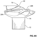
- FIG. 6 a is a side view of the rotatable drive attachment region, the generally circularly shaped hub and the downwardly directed progressively tapered volume with the blades removed of the impeller of FIG. 1 ;
- FIG. 6 b is a side view of the rotatable drive attachment region, the generally circularly shaped hub and the downwardly directed progressively tapered volume with the blades removed of an embodiment of the impeller in accordance with the disclosure wherein the downwardly directed progressively tapered volume has logarithmic taper;
- FIG. 7 is a side perspective view of the embodiment of FIG. 1 showing the rotatable drive attachment region, the generally circularly shaped hub and the downwardly directed progressively tapered volume with the blades removed;
- FIG. 8 is a top perspective view of the embodiment of FIG. 1 showing the rotatable drive attachment region and the generally circularly shaped hub with the blades removed;
- FIG. 9 is a side view of the rotatable drive attachment region, the generally circularly shaped hub and the downwardly directed progressively tapered volume with the blades removed of the impeller of FIG. 1 ;
- FIG. 10 is a bottom plan view of the impeller of FIG. 1 ;
- FIG. 11 is a cutaway side view along line A′ of FIG. 5 of the rotatable drive attachment region, the generally circularly shaped hub and the downwardly directed progressively tapered volume with the blades removed of the impeller of FIG. 1 ;
- FIG. 12 is a cutaway perspective view along line A′ of FIG. 5 of the rotatable drive attachment region, the generally circularly shaped hub and the downwardly directed progressively tapered volume with the blades removed of the impeller of FIG. 1 ;
- FIG. 13 is a graphical representation of a spiral having the general profile of a blade of the impeller of an embodiment of the instant application laid there-over;
- FIG. 14 is schematic side view of an impeller of the instant disclosure mixing a fluid showing the center vortex being drawn upwards into the downwardly directed progressively tapered volume;
- FIG. 15 is a schematic side view of an exemplary cell-culturing bioreactor system maintaining microcarriers in suspension
- FIG. 16A is a pH and temperature versus time plot of pH and temperature of a culture medium in a bioreactor vessel mixed with an axial propeller;
- FIG. 16B is a pH and temperature versus time plot of pH and temperature of a culture medium in a bioreactor vessel mixed with an impeller of the instant disclosure
- FIG. 17A is a dissolved oxygen (pO 2 ) versus time plot of dissolved oxygen in a culture medium in a bioreactor vessel mixed with an axial propeller;
- FIG. 17B is a dissolved oxygen (pO 2 ) versus time plot of dissolved oxygen in a culture medium in a bioreactor vessel mixed with an impeller of the instant disclosure.
- an impeller 10 in accordance with various embodiments of the invention is described below. Additionally, the systems, methods and kit of parts described herein provide, in accordance with different embodiments, different examples in which low shear, low turbulence-generating impellers, including those noted above and the impeller 10 described in detail below, may be used with biodegradable and/or non-biodegradable microcarriers 54 for suspension cell culturing. Although it is contemplated that such a system can be utilized with several different cell types, the present system and method is generally provided for use in stem cell suspension culturing. Since it is contemplated that the presently described systems and method could be used to grow many different cell types in suspension culture, even though the present disclosure is directed to stem cells or, in some instances T-cells, it should not be limited to strictly stem cell suspension cell culturing.
- the impeller 10 has a rotatable drive attachment region 12 coupled to a generally circular shaped hub 14 , as shown, for example, in FIGS. 1, 2 and 3 , where the rotatable drive attachment region 12 is adapted for coupling to a rotatable drive member (not shown).
- the impeller 10 coupled to a rotatable drive member via the rotatable drive attachment region 12 , for example the drive shaft 56 of a motor 58 , the impeller 10 is rotated as the drive shaft is turned.
- the rotation of the impeller 10 results in the fluid being moved in a circular pattern so as to result in mixing of the fluid, as shown in FIG. 14 , for example.
- the impeller 10 has a generally circularly shaped hub 14 with the rotatable drive attachment region 12 coupled to a top side thereof and depending from a bottom side thereof, a downwardly directed progressively tapered volume 16 .
- a plurality of increasingly arced blades 18 arranged along a periodic pattern formed into the downwardly directed progressively tapered volume 16 .
- the number of periods corresponds to the number of increasingly arced blades 18 , for example, as shown in FIG. 10 , five increasingly arced blades 18 .
- the impeller 10 may be provided with only one blade 18 , which, in such a case may follow a single helical period formed into the downwardly directed progressively tapered volume 16 such that the single blade 18 extends helically substantially around the hub 14 thus providing the required balance as the impeller 10 is rotated during use.
- the single blade may be offset by counterbalance weight.
- the increasingly arced blades 18 are coupled to the generally circularly shaped hub 14 at a proximal region 26 a .
- the proximal region 26 a of the blades extend from a peripheral edge region 20 of the hub 14 along the downwardly directed progressively tapered volume 16 to a predetermined point inward 24 of said peripheral edge region 20 .
- FIG. 3 it is shown that the increasingly arced blades 18 are flared as they extend from the progressively tapered volume 16 to a distal end region 26 b of the blades 18 .
- the circumference of the impeller 10 as defined by the distal end regions 26 b of the blades 18 is larger than the circumference of the hub 14 thereby imparting a generally frusto-conical, or flaring, shape to the impeller 10 .
- the distal end regions 26 b of the blades define a larger circumference to the impeller 10 in this distal area than near the hub 14 .
- the blades 18 are flared outwardly as they go from the peripheral end region 26 a , coupled to the hub 14 , to the distal end region 26 b.
- Arrow “A” of FIGS. 5 and 10 shows the direction of rotation of the impeller 10 in use to mix a fluid 50 .
- a leading edge region 38 of the blades 18 is moved though the fluid 50 and the fluid is ejected or discharged, in part, from the impeller 10 at the trailing edge region 40 of the blades 18 thereby aiding to circulate the fluid 50 in a vessel (not shown), in a manner as shown in FIG. 14 , for example.
- the periods of the downwardly directed progressively tapered volume 16 may take the form of, in some embodiments, a plurality of spiral helices 34 formed into the downwardly directed progressively tapered volume 16 .
- each spiral helix 34 is formed by a single period.
- the number of spiral helices 34 corresponds to the number of periods of the hub and thus also the number of increasing radius arced blades 18 .
- the periods or spiral helices 34 begin at the centre of the progressively tapered, at point referred to herein as the progressively tapered volume centre 42 .
- the periods or spiral helices 34 extending from the progressively tapered volume centre 42 , have a ridge component, the spiral ridges 28 a and channel component, the spiral channels or spiraling grooves, 28 b , thus forming a corresponding period.
- the periods may be a raised formation, as opposed to, for example, the channel.
- FIGS. 11 and 12 are side cross-sectional views of the downwardly directed progressively tapered volume 16 and the rotatable drive attachment region 12 along line A′ of FIG. 5 . In these views, the spiral helices 34 and corresponding spiral ridges 28 a and the spiral channels 28 b can be seen.
- the spiral channels 28 b have a semi-circular profiles, as can be seen in the embodiment shown in figures.
- the progressively tapered volume 16 in some embodiments it is provided as having a generally conical shape having the spiral ridges 26 a and spiral 26 b formed in its surface.
- the slope to the conical volume may have angle ⁇ , as shown for example in FIG. 6 a .
- the progressively tapered volume 16 may have a profile such that a cross-sectional profile of progressively tapered volume 16 is not seen as a straight line from the progressively tapered volume centre 42 to the outer peripheral region near the hub 14 . That being, in some embodiments, the progressively tapered volume 16 may have a curved profile and furthermore, an exponentially increasing curve, or in other words a compound logarithmic taper to the volume 16 , as shown for example, in FIG. 6 b.
- the spiral component, formed by the spiral ridges 28 a is provided as a logarithmic spiral.
- the logarithmic spiral pattern as formed on the surface of the progressively tapered volume 16 aids to create the above-noted prewhirl effect along a downward path extending from the progressively tapered volume centre 42 which matches a prewhirl generated by the circumferentially attached increasingly arced blades.
- the spiral channels 28 b or in other words, the swirling channels intermittent the increasingly arced blades allows the vortex created by the blades and motion of the hub to meet and be divided upwardly and outwardly with minimal velocity change to the various regions of the fluid about the hub 14 .
- the swirling internal channels 28 b of the downwardly directed progressively tapered volume of the hub extended into discharge channels 32 a on the upper anterior side of the hub which provide a substantially smooth velocity transition of the fluid in various zones and reduce or substantially eliminate known zones of recirculation as the fluid tangentially flows between adjacent blade ends.
- a height and a depth of the spiral ridges 26 a and the spiral channels 26 b may be variable. For example, one of skill in the art may wish to increase the depth of the spiral channels 26 b in certain applications and decrease it in others. Additionally, in some embodiments, the depth of the spiral channels 26 b may be increased or decreased along a spiral path from the progressively tapered volume centre 42 to the discharge channels 32 b near the peripheral region of the hub 14 .
- FIG. 13 with reference to the terminology of the increasing arced blade, a logarithmic spiral is shown.
- the spiral ridges 28 a are formed along, for example, with reference to FIG. 13 , line “B”.
- line “C” is provided so as to show schematic reference to the peripheral edge region 20 of the generally circularly shaped hub 14 . Therefore, the logarithmic spiral path of the spiral ridges 28 a is shown by line B over-layed and reference to the peripheral edge path of the generally circularly shaped hub 14 by line C.
- the fluid 46 in a vessel is drawn upward into the impeller 10 as a center vortex 48 , as shown in FIG. 14 towards the progressively tapered volume centre 42 .
- the spiral ridges 28 a and the spiral channels 28 b create a prewhirl effect to the fluid.
- the fluid is drawn into the downwardly directed progressively tapered volume centre 42 and then travels along spiral channels 28 b and then forwarded to the peripheral edge region 20 where is it ejected or discharged from the hub region via discharge channels 32 .
- the discharge channels 32 a have a curved peripheral surface 32 b.
- the impeller 10 of the instant disclosure can be formed through joining several independent parts, for example attaching the blades 18 and the rotatable drive attachment region 12 to the hub 14 , in preferred embodiments, the blades 18 and/or the rotatable drive attachment region 12 are integrally formed with the hub 14 . In more preferred embodiments, the impeller 10 and the various components are formed of a monolithic structure. Furthermore, in some embodiments, a connecting ring 36 is provided for joining each blade or blade ends to the next near the distal end region 26 b , as shown in the figures.
- biodegradable and non-biodegradable microcarriers allow cell attachment to a particle that can be left attached to the cell cluster and harvested from the bioreactor once a desired cell confluency is reached.
- the mass of produced cells and biodegradable microcarriers in some embodiments, can then be introduced into a patient or biological system without undertaking a microcarrier separation process since the biodegradable microcarriers will dissolve in the patient's body or biological system over a period of time.
- a separation step such as through the use of trypsinization as is known in the field of cell culturing, may be undertaken so a release the cells from the non-biodegradable microcarrier. In some instance it may be also desirable to undertake such a separation step when utilizing biodegradable microcarriers.
- Biodegradable and non-biodegradable microcarriers are typically used in small applications as a matrix to grow cell structures, typically epithelial cells, yet in the correct stirring conditions can be used to expand suspension cell cultures of various cell types, such as for example, stem cells or T-cells.
- a suspension cell culturing bioreactor 52 suitable for suspension cell culture of various cell types, and in particular embodiments, stem cells.
- a suitable quantity of suitable biodegradable and/or non-biodegradable microcarrier beads 54 such as those commercially available and/or as may be determined by a person of skill in the art as well as a volume of an appropriate cell culture medium and a desired quantity of seed cells (not shown for simplicity).
- the desired quantity of seed cells may be determined by a person of skill in the art so as to render an expanded suspension cell culture through the use of suspension cell culturing.
- biodegradable microcarrier and/or non-biodegradable microcarrier beads 54 Disposed within the bioreactor having therein the above-noted cell culture medium, biodegradable microcarrier and/or non-biodegradable microcarrier beads 54 , which in some instance may have a relative density versus H 2 O similar to biodegradable microcarrier beads, and seed cells is a rotatably-driven impeller, such as impeller 10 , designed to impart a swirling motion to the culture medium 60 which can maintain the microcarriers in suspension in a low shear and/or low turbulence environment.
- the rotatably-driven impeller is driven the coupled impeller drive shaft 56 operatively coupled to motor 58 .
- the motor 58 may be capable or rotation in both a clock-wise or counter clockwise direction as may be selected by an operator.
- the microcarriers, and in particular the non-biodegradable microcarriers may have a relative density versus H 2 O of greater than being neutrally buoyant.
- the biodegradable microcarrier beads and/or non-biodegradable microcarrier beads have a relative density versus H 2 O of from about 1.01 cm 2 /g to about 1.3 cm 2 /g.
- the biodegradable microcarrier beads and/or non-biodegradable microcarrier beads have a relative density versus H 2 O of from about 1.01 cm 2 /g to about 1.2 cm 2 /g.
- the total number of cells seeded in both the suspension culture mixed with the axial propeller and the impeller 10 as disclosed herein was 8.64E+07.
- the harvesting efficiency for both of the impellers was greater than 98%.
- the impeller 10 of the instant disclosure showed a more rapid cell detachment, which was observed at 7.5 min.
- the number of viable cells harvested from the bioreactor suspension cell culture mixed with impeller 10 was 95% as compared to the number of viable cells harvested from the bioreactor suspension culture mixed with the axial propeller being 83%. Therefore, the suspension culture mixed with the impeller 10 of the instant disclosure showed a 12% increase in number of viable cells recovered over the axial propeller.
- the impeller 10 of the instant disclosure was compared to an axial propeller in a bioreactor system for suspension culturing in order to determine and compare the pH (element E in FIG. 16A ; element G in FIG. 16B ) and temperature (element F in FIG. 16A ; element H in FIG. 16B ) conditions over time in: 1) a bioreactor system wherein the culture media is mixed with an axial propeller, as shown in FIG. 16A ; and 2) a bioreactor system wherein the culture media is mixed with an impeller 10 as disclosed herein, as shown in FIG. 16B .
- dissolved oxygen levels pO 2
- FIG. 17A shows the dissolved oxygen levels over time in relation to a culture medium in a bioreactor mixed with an axial propeller
- FIG. 17B shows dissolved oxygen levels over time in relation to a culture medium in a bioreactor mixed with an impeller 10 as disclosed herein.
- the exemplary were results taken over a 150-hour time period.
- FIGS. 16B and 17B indicate a stabilization of the fluid flow within the bioreactor which results in a more steady state as compared to using an axial propeller, as shown in FIGS. 16A and 17A .
- the date indicates that all areas of the fluid in the bioreactor mixed with the impeller 10 of the instant disclosure are evenly mixed to a point that there are no regions of the vessel that differ in characteristics from each other, thus indicating a uniform distribution.
- FIGS. 16B and 17B indicate a stabilization of the fluid flow within the bioreactor which results in a more steady state as compared to using an axial propeller, as shown in FIGS. 16A and 17A .
- the impeller 10 of the instant disclosure shows a flat line of dissolved oxygen and pH readings, as shown in FIGS. 16B and 17B thereby indicating that all zones of the fluid in motion in the bioreactor have an equal measurement due to a more complete mixing and thus the interior of the bioreactor vessel can be considered one mixing zone.
- readings such as dissolved oxygen and PH, show spikes of high and low during the mixing which indicates that there are several fluid mixing zones.
- Suitable conical impellers in additional to the impeller 10 described in detailed herein, such as those disclosed in U.S. Pat. No. 5,314,310, entitled “SPIDER MOUNTED CENTRIFUGAL MIXING IMPELLER”, issued May 24, 1994 (Bachellier, Carl R.), U.S. Pat. No. 5,938,332, entitled “MIXING DEVICE”, issued Aug. 17, 1999 (Bachellier, Carl R.) and International Patent Application serial number PCT/CA2012/050873, entitled “IMPROVED IMPELLER APPARATUS AND DISPERSION METHOD FIELD OF THE INVENTION”, filed Dec.
- impellers may be suitable for suspension cell culturing utilizing biodegradable microcarriers and/or non-biodegradable microcarriers which may have a relative density versus H 2 O of greater than being neutrally buoyant
- the invention is not so limited and other existing or future impeller designs may also be suitable in the instantly disclosed system and method.
- Another consideration, regardless of the impeller design chosen to stir the culture medium 60 is providing a drive shaft 56 for driving the impeller which only partially extends into to the bioreactor.
- a depth may be determined by one of skill in the art, however, a low shear and low turbulence environment may further be enhanced or achieved since a guidance peg on the bottom of the bioreactor vessel, as commonly present in currently available bioreactor designs, which may further cause unwanted fluid disruption or turbulence may not be present or necessary.
- a guidance peg on the bottom of the bioreactor vessel as commonly present in currently available bioreactor designs, which may further cause unwanted fluid disruption or turbulence may not be present or necessary.
- the elimination of one or more guidance pegs may allow for smoother, and thus, less turbulent fluid flow of the culture medium in use during the suspension cell culturing.
- the instantly disclosed system may enable the suspension cell culturing with biodegradable microcarriers and/or non-biodegradable microcarriers which may have a relative density versus H 2 O of greater than being neutrally buoyant in larger scale bioreactors, such as for example, up to and greater than fifty-litre volumes.
- the instantly disclosed system may be provided as a complete system in which only seed cells need to be added by an end-user.
- the system may be provided as a bioreactor, having therein suitable biodegradable and on-biodegradable microcarrier beads, and a suitable drivable impeller operably disposed therein.
- an end user may simply add a suitable quantity of desired seed cells and suspension culture medium 60 , introduce and maintain the system to a suitable environment and connect a drive shaft 56 , connected to the impeller, to a motor 58 and apply a force to cause rotation of the impeller.
- such a prepared system may be provided complete with a suitable culture medium preinstalled for a given cell type.
Landscapes
- Chemical & Material Sciences (AREA)
- Engineering & Computer Science (AREA)
- Health & Medical Sciences (AREA)
- Organic Chemistry (AREA)
- Wood Science & Technology (AREA)
- Life Sciences & Earth Sciences (AREA)
- Bioinformatics & Cheminformatics (AREA)
- Zoology (AREA)
- Chemical Kinetics & Catalysis (AREA)
- Biotechnology (AREA)
- Microbiology (AREA)
- Biochemistry (AREA)
- General Engineering & Computer Science (AREA)
- General Health & Medical Sciences (AREA)
- Genetics & Genomics (AREA)
- Sustainable Development (AREA)
- Biomedical Technology (AREA)
- Aviation & Aerospace Engineering (AREA)
- Mixers Of The Rotary Stirring Type (AREA)
- Apparatus Associated With Microorganisms And Enzymes (AREA)
- Immunology (AREA)
- Micro-Organisms Or Cultivation Processes Thereof (AREA)
Abstract
Description
-
- introducing into a fluid an impeller coupled to a rotatable drive shaft;
- the impeller comprising a generally circularly shaped hub, including a downwardly directed progressively tapered volume having coupled thereto a proximal end region of one or more arced blades arranged along a periodic pattern formed into the downwardly directed progressively tapered volume wherein the number of periods corresponds to the number of blades;
- each of the one or more arced blades having an increasing radius to the arc towards a peripheral edge region of said hub;
- the proximal end region of the at one or more increasing radius arced blades extending from the peripheral edge region of the hub along the downwardly directed progressively tapered volume to a predetermined point inward of the peripheral edge region;
- the one or more arced blades further being flared as extending from the progressively tapered volume such that a distal end region of each of the one or more increasing radius arced blades, in combination, defines a larger circumference than that of the hub, thereby imparting a generally frusto-conical shape to the impeller;
- causing the impeller to rotate in the direction of the predetermined point inward of the peripheral edge region;
- by rotating of the impeller, creating a fluid vortex channeled upwards to a centre point of the progressively tapered volume so as to create a prewhirl to the fluid about a region near the hub, the velocity of which substantially matching the velocity of the fluid moving near the increasingly arced blades; and
- tangentially discharging the fluid between adjacent ends of the one or more increasingly arced blades so as mix the fluid.
-
- introducing into a fluid an impeller coupled to a rotatable drive shaft;
- the impeller comprising a generally circularly shaped hub including a downwardly directed progressively tapered volume having coupled thereto toward a peripheral end region thereof one or more flaring arced blades arranged along a periodic pattern formed into the downwardly directed progressively tapered volume to project generally downwards from the peripheral edge region and to define a periodically flaring impeller radius along their length which allows for tangential fluid flow between adjacent blade ends;
- rotating of the impeller so as to create a fluid vortex channeled upwards to a centre point of the progressively tapered volume so as to create a prewhirl to the fluid about a region near the hub, the velocity of which substantially matching the velocity of the fluid moving near the one or more flaring arced blades; and tangentially discharging the fluid between adjacent ends of said one or more flaring arced blades so as mix the fluid.
-
- providing a suspension cell culturing bioreactor vessel having disposed therein an impeller for stirring a culture medium operably coupled to a selectively-reversible rotatable drive shaft driveable by a motor; the impeller characterized in that during use the impeller, when rotated, imparts sufficient motion to the culture medium contained with the bioreactor vessel to maintain a plurality of biodegradable microcarrier and/or non-biodegradable microcarrier beads in suspension in an environment substantially-free from mechanical stresses to the cultureable cells;
- providing the plurality of biodegradable microcarrier and/or non-biodegradable microcarrier beads and introducing the plurality of biodegradable microcarrier and/or non-biodegradable microcarrier beads into the bioreactor;
- providing the suitable culture medium and the suitable quantity of culturable cells;
- providing suitable conditions for culturing the culturable cells; and
- culturing the culturable cells.
| TABLE 1 | ||||
| Harvest Output | | Impeller | 10 | |
| Total Cells | 1.17E+09 | 1.38E+09 | ||
| Viable Cells | 1.01E+09 | 1.31E+09 | ||
| Percent recovered cell | 83% | 95% | ||
| viability | ||||
Claims (16)
Priority Applications (1)
| Application Number | Priority Date | Filing Date | Title |
|---|---|---|---|
| US16/169,354 US11117107B2 (en) | 2016-07-18 | 2018-10-24 | Low shear, low velocity differential, impeller having a progressively tapered hub volume with periods formed into a bottom surface, systems and methods for suspension cell culturing |
Applications Claiming Priority (5)
| Application Number | Priority Date | Filing Date | Title |
|---|---|---|---|
| CA2936339A CA2936339C (en) | 2016-07-18 | 2016-07-18 | Low shear, low velocity differential, impeller having a progressively tapered hub volume with periods formed into a bottom surface |
| CA2936339 | 2016-07-18 | ||
| PCT/CA2017/050845 WO2018014114A1 (en) | 2016-07-18 | 2017-07-11 | Low shear, low velocity differential, impeller having a progressively tapered hub volume with periods formed into a bottom surface |
| US201762577933P | 2017-10-27 | 2017-10-27 | |
| US16/169,354 US11117107B2 (en) | 2016-07-18 | 2018-10-24 | Low shear, low velocity differential, impeller having a progressively tapered hub volume with periods formed into a bottom surface, systems and methods for suspension cell culturing |
Related Parent Applications (1)
| Application Number | Title | Priority Date | Filing Date |
|---|---|---|---|
| PCT/CA2017/050845 Continuation-In-Part WO2018014114A1 (en) | 2016-07-18 | 2017-07-11 | Low shear, low velocity differential, impeller having a progressively tapered hub volume with periods formed into a bottom surface |
Publications (2)
| Publication Number | Publication Date |
|---|---|
| US20190054432A1 US20190054432A1 (en) | 2019-02-21 |
| US11117107B2 true US11117107B2 (en) | 2021-09-14 |
Family
ID=60989371
Family Applications (1)
| Application Number | Title | Priority Date | Filing Date |
|---|---|---|---|
| US16/169,354 Active 2038-08-14 US11117107B2 (en) | 2016-07-18 | 2018-10-24 | Low shear, low velocity differential, impeller having a progressively tapered hub volume with periods formed into a bottom surface, systems and methods for suspension cell culturing |
Country Status (5)
| Country | Link |
|---|---|
| US (1) | US11117107B2 (en) |
| EP (1) | EP3484606B1 (en) |
| CA (1) | CA2936339C (en) |
| DK (1) | DK3484606T3 (en) |
| WO (1) | WO2018014114A1 (en) |
Cited By (2)
| Publication number | Priority date | Publication date | Assignee | Title |
|---|---|---|---|---|
| US11958026B2 (en) | 2021-09-15 | 2024-04-16 | Sanisure, Inc. | Low volume magnetic mixing system |
| WO2025054708A1 (en) * | 2023-09-13 | 2025-03-20 | Silent Propulsion Inc. | Fluid displacement or propulsion device having a progressively tapered hub volume with periods formed into a surface, system and methods for moving a fluid or causing propulsion |
Families Citing this family (8)
| Publication number | Priority date | Publication date | Assignee | Title |
|---|---|---|---|---|
| CA2936339C (en) * | 2016-07-18 | 2019-02-12 | Carl R. Bachellier | Low shear, low velocity differential, impeller having a progressively tapered hub volume with periods formed into a bottom surface |
| EP3986603B1 (en) * | 2019-06-24 | 2024-09-18 | Global Life Sciences Solutions USA LLC | Bioreactor support system |
| CN114981402A (en) * | 2020-01-27 | 2022-08-30 | Pbs生物技术公司 | Systems and methods for scalable production of therapeutic cells in bioreactors |
| CN112772292B (en) * | 2021-03-09 | 2023-07-04 | 贵州贵旺生物科技有限公司 | Pleurotus eryngii liquid culture medium preparation system |
| EP4388203A4 (en) * | 2021-10-06 | 2024-12-25 | N. Arumugam | INDUCTOR ASSISTED MIXED FLOW CEILING FAN |
| CN114602341A (en) * | 2022-03-21 | 2022-06-10 | 四川大学 | Stirring paddles and cell bioreactors for cell culture |
| CN114736797A (en) * | 2022-03-30 | 2022-07-12 | 昆明柏特生物科技有限公司 | A cell culture reactor |
| CN117431144B (en) * | 2023-09-28 | 2024-06-21 | 深圳睿生生物工程有限公司 | Stirring wheel and bioreactor |
Citations (25)
| Publication number | Priority date | Publication date | Assignee | Title |
|---|---|---|---|---|
| US3644056A (en) * | 1970-03-06 | 1972-02-22 | Koninkl Maschf Stork Nv | Centrifugal pump |
| US4093401A (en) * | 1976-04-12 | 1978-06-06 | Sundstrand Corporation | Compressor impeller and method of manufacture |
| US4468358A (en) * | 1980-07-08 | 1984-08-28 | Haegeman Johny H | Apparatus for mixing air and liquid |
| US4594052A (en) * | 1982-02-08 | 1986-06-10 | A. Ahlstrom Osakeyhtio | Centrifugal pump for liquids containing solid material |
| US4647215A (en) * | 1983-09-19 | 1987-03-03 | Envirotech Corporation | Ragless propeller draft tube mixer |
| US5314310A (en) * | 1986-05-07 | 1994-05-24 | Bachellier Carl R | Spider mounted centrifugal mixing impeller |
| US5938332A (en) * | 1997-10-27 | 1999-08-17 | Bachellier; Carl R. | Mixing device |
| US6158959A (en) * | 1997-11-18 | 2000-12-12 | Itt Manufacturing Enterprises, Inc. | Pump impeller |
| US7597541B2 (en) * | 2005-07-12 | 2009-10-06 | Robert Bosch Llc | Centrifugal fan assembly |
| US20100061841A1 (en) * | 2008-09-11 | 2010-03-11 | Visintainer Robert J | Froth handling pump |
| US20100135765A1 (en) * | 2007-05-21 | 2010-06-03 | Kevin Edward Burgess | Pumps |
| WO2011051880A2 (en) | 2009-10-26 | 2011-05-05 | Spal Automotive S.R.L. | Axial ventilator |
| US20110194931A1 (en) * | 2010-02-05 | 2011-08-11 | Cameron International Corporation | Centrifugal compressor diffuser vanelet |
| GB2486019A (en) * | 2010-12-02 | 2012-06-06 | Dyson Technology Ltd | Fan impeller |
| WO2013082717A1 (en) | 2011-12-06 | 2013-06-13 | Bachellier Carl Roy | Improved impeller apparatus and dispersion method |
| CA2872355A1 (en) | 2013-12-16 | 2015-06-16 | Pall Corporation | High turndown impeller |
| US20150292523A1 (en) * | 2014-04-14 | 2015-10-15 | Enevor Inc. | Conical Impeller and Applications Thereof |
| WO2016165795A1 (en) * | 2015-04-15 | 2016-10-20 | Sulzer Management Ag | An impeller for a centrifugal headbox feed pump |
| US20170096628A1 (en) * | 2014-04-14 | 2017-04-06 | Enevor Inc. | Conical Impeller and Applications Thereof |
| US9868155B2 (en) * | 2014-03-20 | 2018-01-16 | Ingersoll-Rand Company | Monolithic shrouded impeller |
| US9920768B2 (en) * | 2015-03-26 | 2018-03-20 | Deere & Company | Centrifugal fan assembly |
| US20190054432A1 (en) * | 2016-07-18 | 2019-02-21 | Cellmotions Inc. | Low shear, low velocity differential, impeller having a progressively tapered hub volume with periods formed into a bottom surface, systems and methods for suspension cell culturing |
| US10371154B2 (en) * | 2012-07-25 | 2019-08-06 | Halliburton Energy Services, Inc. | Apparatus, system and method for pumping gaseous fluid |
| US10527053B2 (en) * | 2013-12-31 | 2020-01-07 | Ningbo Fotile Kitchen Ware Co., Ltd. | Open water pump |
| US10550854B2 (en) * | 2014-05-05 | 2020-02-04 | Ziehl-Abegg Se | Impeller wheel for diagonal or radial fans, injection molding tool for manufacturing such an impeller wheel, and device comprising such an impeller wheel |
Family Cites Families (1)
| Publication number | Priority date | Publication date | Assignee | Title |
|---|---|---|---|---|
| DE1542357A1 (en) * | 1951-01-28 | 1972-02-17 | Oestberg Jan Erik | Arrangement for the formation of a flow in the reaction zone between two fluids of different specific gravity in a container |
-
2016
- 2016-07-18 CA CA2936339A patent/CA2936339C/en active Active
-
2017
- 2017-07-11 WO PCT/CA2017/050845 patent/WO2018014114A1/en not_active Ceased
- 2017-07-11 EP EP17830137.0A patent/EP3484606B1/en active Active
- 2017-07-11 DK DK17830137.0T patent/DK3484606T3/en active
-
2018
- 2018-10-24 US US16/169,354 patent/US11117107B2/en active Active
Patent Citations (34)
| Publication number | Priority date | Publication date | Assignee | Title |
|---|---|---|---|---|
| US3644056A (en) * | 1970-03-06 | 1972-02-22 | Koninkl Maschf Stork Nv | Centrifugal pump |
| US4093401A (en) * | 1976-04-12 | 1978-06-06 | Sundstrand Corporation | Compressor impeller and method of manufacture |
| US4468358A (en) * | 1980-07-08 | 1984-08-28 | Haegeman Johny H | Apparatus for mixing air and liquid |
| US4594052A (en) * | 1982-02-08 | 1986-06-10 | A. Ahlstrom Osakeyhtio | Centrifugal pump for liquids containing solid material |
| US4647215A (en) * | 1983-09-19 | 1987-03-03 | Envirotech Corporation | Ragless propeller draft tube mixer |
| US5314310A (en) * | 1986-05-07 | 1994-05-24 | Bachellier Carl R | Spider mounted centrifugal mixing impeller |
| US5938332A (en) * | 1997-10-27 | 1999-08-17 | Bachellier; Carl R. | Mixing device |
| US6158959A (en) * | 1997-11-18 | 2000-12-12 | Itt Manufacturing Enterprises, Inc. | Pump impeller |
| US7597541B2 (en) * | 2005-07-12 | 2009-10-06 | Robert Bosch Llc | Centrifugal fan assembly |
| US20100135765A1 (en) * | 2007-05-21 | 2010-06-03 | Kevin Edward Burgess | Pumps |
| US20100061841A1 (en) * | 2008-09-11 | 2010-03-11 | Visintainer Robert J | Froth handling pump |
| WO2011051880A2 (en) | 2009-10-26 | 2011-05-05 | Spal Automotive S.R.L. | Axial ventilator |
| WO2011051880A3 (en) | 2009-10-26 | 2011-06-23 | Spal Automotive S.R.L. | Axial ventilator |
| US8985970B2 (en) * | 2009-10-26 | 2015-03-24 | Spal Automotive S.R.L. | Axial ventilator |
| US20110194931A1 (en) * | 2010-02-05 | 2011-08-11 | Cameron International Corporation | Centrifugal compressor diffuser vanelet |
| US9745996B2 (en) * | 2010-12-02 | 2017-08-29 | Dyson Technology Limited | Fan |
| GB2486019A (en) * | 2010-12-02 | 2012-06-06 | Dyson Technology Ltd | Fan impeller |
| WO2013082717A1 (en) | 2011-12-06 | 2013-06-13 | Bachellier Carl Roy | Improved impeller apparatus and dispersion method |
| US20140349379A1 (en) * | 2011-12-06 | 2014-11-27 | Enevor Inc. | Impeller Apparatus and Dispersion Method |
| US9682348B2 (en) * | 2011-12-06 | 2017-06-20 | Enevor Inc. | Impeller apparatus and dispersion method |
| US10371154B2 (en) * | 2012-07-25 | 2019-08-06 | Halliburton Energy Services, Inc. | Apparatus, system and method for pumping gaseous fluid |
| CA2872355A1 (en) | 2013-12-16 | 2015-06-16 | Pall Corporation | High turndown impeller |
| US10527053B2 (en) * | 2013-12-31 | 2020-01-07 | Ningbo Fotile Kitchen Ware Co., Ltd. | Open water pump |
| US9868155B2 (en) * | 2014-03-20 | 2018-01-16 | Ingersoll-Rand Company | Monolithic shrouded impeller |
| WO2015160850A1 (en) | 2014-04-14 | 2015-10-22 | Enevor Inc. | Conical impeller and applications thereof |
| US9863423B2 (en) * | 2014-04-14 | 2018-01-09 | Enevor Inc. | Conical impeller and applications thereof |
| US20170096628A1 (en) * | 2014-04-14 | 2017-04-06 | Enevor Inc. | Conical Impeller and Applications Thereof |
| US20150292523A1 (en) * | 2014-04-14 | 2015-10-15 | Enevor Inc. | Conical Impeller and Applications Thereof |
| US10550854B2 (en) * | 2014-05-05 | 2020-02-04 | Ziehl-Abegg Se | Impeller wheel for diagonal or radial fans, injection molding tool for manufacturing such an impeller wheel, and device comprising such an impeller wheel |
| US9920768B2 (en) * | 2015-03-26 | 2018-03-20 | Deere & Company | Centrifugal fan assembly |
| US20180112673A1 (en) * | 2015-04-15 | 2018-04-26 | Sulzer Management Ag | Impeller for a centrifugal headbox feed pump |
| US10247195B2 (en) * | 2015-04-15 | 2019-04-02 | Sulzer Management Ag | Impeller for a centrifugal headbox feed pump |
| WO2016165795A1 (en) * | 2015-04-15 | 2016-10-20 | Sulzer Management Ag | An impeller for a centrifugal headbox feed pump |
| US20190054432A1 (en) * | 2016-07-18 | 2019-02-21 | Cellmotions Inc. | Low shear, low velocity differential, impeller having a progressively tapered hub volume with periods formed into a bottom surface, systems and methods for suspension cell culturing |
Non-Patent Citations (4)
| Title |
|---|
| "Corning Synthemax II Microcarriers, Dissolvable, 5g, Sterile"; Corning Incorporated Life Sciences; Catalog No. 4988; 2018. |
| "Expansion and Characterization of Mesenchymal Stem Cells on Pall SoloHill Microcarriers"; Pall Life Sciences; 2015; pp. 1-12. |
| "Human Mesenchymal Stem Cell Growth on Corning Denatured Collagen Dissolvable Microcamers in a 5L Bioreactor"; Weber et al.; Oct. 2017; pp. 1-8. |
| "Microcarrier Cell Culture Principles and Methods"; GE Healthcare Life Sciences Handbooks; 2005-2013 General Electric Company—First Published Apr. 2005; pp. 1-171. |
Cited By (3)
| Publication number | Priority date | Publication date | Assignee | Title |
|---|---|---|---|---|
| US11958026B2 (en) | 2021-09-15 | 2024-04-16 | Sanisure, Inc. | Low volume magnetic mixing system |
| US12377392B2 (en) | 2021-09-15 | 2025-08-05 | Sanisure, Inc. | Low volume magnetic mixing system |
| WO2025054708A1 (en) * | 2023-09-13 | 2025-03-20 | Silent Propulsion Inc. | Fluid displacement or propulsion device having a progressively tapered hub volume with periods formed into a surface, system and methods for moving a fluid or causing propulsion |
Also Published As
| Publication number | Publication date |
|---|---|
| CA2936339A1 (en) | 2018-01-18 |
| EP3484606A4 (en) | 2019-08-14 |
| CA2936339C (en) | 2019-02-12 |
| WO2018014114A1 (en) | 2018-01-25 |
| EP3484606B1 (en) | 2020-11-25 |
| US20190054432A1 (en) | 2019-02-21 |
| DK3484606T3 (en) | 2021-03-01 |
| EP3484606A1 (en) | 2019-05-22 |
Similar Documents
| Publication | Publication Date | Title |
|---|---|---|
| US11117107B2 (en) | Low shear, low velocity differential, impeller having a progressively tapered hub volume with periods formed into a bottom surface, systems and methods for suspension cell culturing | |
| US11185799B2 (en) | Particle settling devices | |
| JP4279669B2 (en) | Unit and method for performing high cell density fermentation | |
| WO2016054939A1 (en) | Tube having spiral protrusion on inner wall and photobioreactor thereof | |
| CN205115475U (en) | Ventilating fermentation tank | |
| US20100144022A1 (en) | Continuous Flow Bioreactor | |
| CN101827644A (en) | Stirring device, method and stirring element therefor, and computer program for stirring viscous fluid by using said device | |
| US11679345B2 (en) | Particle settling devices | |
| RU2135579C1 (en) | Apparatus for suspension cultivation of cells of tissues and microorganisms | |
| AU2008340237B2 (en) | Method and apparatus for mixing | |
| CN107636140A (en) | For producing the fermentation tank of shear thinning medium | |
| CA3021960A1 (en) | System, method and kit of parts for suspension cell culturing with microcarriers | |
| CN113813812B (en) | A new type of stirring paddle and a stirring paddle system and fermentation method suitable for fermentation of high-viscosity materials | |
| US20230121588A1 (en) | Particle settling devices inside bioreactors | |
| HK40003242B (en) | Low shear, low velocity differential, impeller having a progressively tapered hub volume with periods formed into a bottom surface and methods of mixing therewith | |
| CN117431144B (en) | Stirring wheel and bioreactor | |
| CN201981204U (en) | Bioreactor for culturing cells | |
| CN221822172U (en) | An alkaline lysis device for preparing plasmid DNA | |
| US20200347334A1 (en) | Macrocarriers for cell growth in bioreactors | |
| RU2295571C2 (en) | Method for production of preparative amounts of plasmid dna from recombinant microorganism cells | |
| WO2024056037A1 (en) | Liquid drawing device, bioreactor, and liquid drawing method | |
| JPS609482A (en) | Highly-concentrated cultivation of floating cell and its device |
Legal Events
| Date | Code | Title | Description |
|---|---|---|---|
| AS | Assignment |
Owner name: CELLMOTIONS INC., CANADA Free format text: ASSIGNMENT OF ASSIGNORS INTEREST;ASSIGNOR:BACHELLIER, CARL R;REEL/FRAME:047299/0988 Effective date: 20170707 |
|
| FEPP | Fee payment procedure |
Free format text: ENTITY STATUS SET TO UNDISCOUNTED (ORIGINAL EVENT CODE: BIG.); ENTITY STATUS OF PATENT OWNER: SMALL ENTITY |
|
| FEPP | Fee payment procedure |
Free format text: ENTITY STATUS SET TO SMALL (ORIGINAL EVENT CODE: SMAL); ENTITY STATUS OF PATENT OWNER: SMALL ENTITY |
|
| STPP | Information on status: patent application and granting procedure in general |
Free format text: DOCKETED NEW CASE - READY FOR EXAMINATION |
|
| STPP | Information on status: patent application and granting procedure in general |
Free format text: NON FINAL ACTION MAILED |
|
| STPP | Information on status: patent application and granting procedure in general |
Free format text: RESPONSE TO NON-FINAL OFFICE ACTION ENTERED AND FORWARDED TO EXAMINER |
|
| STPP | Information on status: patent application and granting procedure in general |
Free format text: NOTICE OF ALLOWANCE MAILED -- APPLICATION RECEIVED IN OFFICE OF PUBLICATIONS |
|
| STPP | Information on status: patent application and granting procedure in general |
Free format text: AWAITING TC RESP., ISSUE FEE NOT PAID |
|
| STPP | Information on status: patent application and granting procedure in general |
Free format text: NOTICE OF ALLOWANCE MAILED -- APPLICATION RECEIVED IN OFFICE OF PUBLICATIONS |
|
| STPP | Information on status: patent application and granting procedure in general |
Free format text: NOTICE OF ALLOWANCE MAILED -- APPLICATION RECEIVED IN OFFICE OF PUBLICATIONS |
|
| STPP | Information on status: patent application and granting procedure in general |
Free format text: PUBLICATIONS -- ISSUE FEE PAYMENT VERIFIED |
|
| STCF | Information on status: patent grant |
Free format text: PATENTED CASE |
|
| MAFP | Maintenance fee payment |
Free format text: PAYMENT OF MAINTENANCE FEE, 4TH YR, SMALL ENTITY (ORIGINAL EVENT CODE: M2551); ENTITY STATUS OF PATENT OWNER: SMALL ENTITY Year of fee payment: 4 |