US11094964B2 - Rechargeable electrochemical cell - Google Patents
Rechargeable electrochemical cell Download PDFInfo
- Publication number
- US11094964B2 US11094964B2 US16/462,419 US201716462419A US11094964B2 US 11094964 B2 US11094964 B2 US 11094964B2 US 201716462419 A US201716462419 A US 201716462419A US 11094964 B2 US11094964 B2 US 11094964B2
- Authority
- US
- United States
- Prior art keywords
- group
- alkyl
- electrochemical cell
- phosphonate
- set forth
- Prior art date
- Legal status (The legal status is an assumption and is not a legal conclusion. Google has not performed a legal analysis and makes no representation as to the accuracy of the status listed.)
- Active, expires
Links
- 0 [1*]C1=CC([4*])=C2C(=C1)S(=O)(=O)C1=C(C([5*])=CC([2*])=C1)N2[3*] Chemical compound [1*]C1=CC([4*])=C2C(=C1)S(=O)(=O)C1=C(C([5*])=CC([2*])=C1)N2[3*] 0.000 description 10
Classifications
-
- H—ELECTRICITY
- H01—ELECTRIC ELEMENTS
- H01M—PROCESSES OR MEANS, e.g. BATTERIES, FOR THE DIRECT CONVERSION OF CHEMICAL ENERGY INTO ELECTRICAL ENERGY
- H01M10/00—Secondary cells; Manufacture thereof
- H01M10/05—Accumulators with non-aqueous electrolyte
- H01M10/052—Li-accumulators
-
- C—CHEMISTRY; METALLURGY
- C07—ORGANIC CHEMISTRY
- C07D—HETEROCYCLIC COMPOUNDS
- C07D279/00—Heterocyclic compounds containing six-membered rings having one nitrogen atom and one sulfur atom as the only ring hetero atoms
- C07D279/10—1,4-Thiazines; Hydrogenated 1,4-thiazines
- C07D279/14—1,4-Thiazines; Hydrogenated 1,4-thiazines condensed with carbocyclic rings or ring systems
- C07D279/18—[b, e]-condensed with two six-membered rings
- C07D279/34—[b, e]-condensed with two six-membered rings with hetero atoms directly attached to the ring sulfur atom
-
- H—ELECTRICITY
- H01—ELECTRIC ELEMENTS
- H01G—CAPACITORS; CAPACITORS, RECTIFIERS, DETECTORS, SWITCHING DEVICES, LIGHT-SENSITIVE OR TEMPERATURE-SENSITIVE DEVICES OF THE ELECTROLYTIC TYPE
- H01G11/00—Hybrid capacitors, i.e. capacitors having different positive and negative electrodes; Electric double-layer [EDL] capacitors; Processes for the manufacture thereof or of parts thereof
- H01G11/02—Hybrid capacitors, i.e. capacitors having different positive and negative electrodes; Electric double-layer [EDL] capacitors; Processes for the manufacture thereof or of parts thereof using combined reduction-oxidation reactions, e.g. redox arrangement or solion
-
- H—ELECTRICITY
- H01—ELECTRIC ELEMENTS
- H01G—CAPACITORS; CAPACITORS, RECTIFIERS, DETECTORS, SWITCHING DEVICES, LIGHT-SENSITIVE OR TEMPERATURE-SENSITIVE DEVICES OF THE ELECTROLYTIC TYPE
- H01G11/00—Hybrid capacitors, i.e. capacitors having different positive and negative electrodes; Electric double-layer [EDL] capacitors; Processes for the manufacture thereof or of parts thereof
- H01G11/14—Arrangements or processes for adjusting or protecting hybrid or EDL capacitors
- H01G11/16—Arrangements or processes for adjusting or protecting hybrid or EDL capacitors against electric overloads, e.g. including fuses
-
- H—ELECTRICITY
- H01—ELECTRIC ELEMENTS
- H01G—CAPACITORS; CAPACITORS, RECTIFIERS, DETECTORS, SWITCHING DEVICES, LIGHT-SENSITIVE OR TEMPERATURE-SENSITIVE DEVICES OF THE ELECTROLYTIC TYPE
- H01G11/00—Hybrid capacitors, i.e. capacitors having different positive and negative electrodes; Electric double-layer [EDL] capacitors; Processes for the manufacture thereof or of parts thereof
- H01G11/54—Electrolytes
- H01G11/58—Liquid electrolytes
- H01G11/60—Liquid electrolytes characterised by the solvent
-
- H—ELECTRICITY
- H01—ELECTRIC ELEMENTS
- H01G—CAPACITORS; CAPACITORS, RECTIFIERS, DETECTORS, SWITCHING DEVICES, LIGHT-SENSITIVE OR TEMPERATURE-SENSITIVE DEVICES OF THE ELECTROLYTIC TYPE
- H01G11/00—Hybrid capacitors, i.e. capacitors having different positive and negative electrodes; Electric double-layer [EDL] capacitors; Processes for the manufacture thereof or of parts thereof
- H01G11/54—Electrolytes
- H01G11/58—Liquid electrolytes
- H01G11/62—Liquid electrolytes characterised by the solute, e.g. salts, anions or cations therein
-
- H—ELECTRICITY
- H01—ELECTRIC ELEMENTS
- H01G—CAPACITORS; CAPACITORS, RECTIFIERS, DETECTORS, SWITCHING DEVICES, LIGHT-SENSITIVE OR TEMPERATURE-SENSITIVE DEVICES OF THE ELECTROLYTIC TYPE
- H01G11/00—Hybrid capacitors, i.e. capacitors having different positive and negative electrodes; Electric double-layer [EDL] capacitors; Processes for the manufacture thereof or of parts thereof
- H01G11/54—Electrolytes
- H01G11/58—Liquid electrolytes
- H01G11/64—Liquid electrolytes characterised by additives
-
- H—ELECTRICITY
- H01—ELECTRIC ELEMENTS
- H01M—PROCESSES OR MEANS, e.g. BATTERIES, FOR THE DIRECT CONVERSION OF CHEMICAL ENERGY INTO ELECTRICAL ENERGY
- H01M10/00—Secondary cells; Manufacture thereof
- H01M10/05—Accumulators with non-aqueous electrolyte
- H01M10/052—Li-accumulators
- H01M10/0525—Rocking-chair batteries, i.e. batteries with lithium insertion or intercalation in both electrodes; Lithium-ion batteries
-
- H—ELECTRICITY
- H01—ELECTRIC ELEMENTS
- H01M—PROCESSES OR MEANS, e.g. BATTERIES, FOR THE DIRECT CONVERSION OF CHEMICAL ENERGY INTO ELECTRICAL ENERGY
- H01M10/00—Secondary cells; Manufacture thereof
- H01M10/05—Accumulators with non-aqueous electrolyte
- H01M10/056—Accumulators with non-aqueous electrolyte characterised by the materials used as electrolytes, e.g. mixed inorganic/organic electrolytes
- H01M10/0564—Accumulators with non-aqueous electrolyte characterised by the materials used as electrolytes, e.g. mixed inorganic/organic electrolytes the electrolyte being constituted of organic materials only
- H01M10/0566—Liquid materials
- H01M10/0567—Liquid materials characterised by the additives
-
- H—ELECTRICITY
- H01—ELECTRIC ELEMENTS
- H01M—PROCESSES OR MEANS, e.g. BATTERIES, FOR THE DIRECT CONVERSION OF CHEMICAL ENERGY INTO ELECTRICAL ENERGY
- H01M10/00—Secondary cells; Manufacture thereof
- H01M10/42—Methods or arrangements for servicing or maintenance of secondary cells or secondary half-cells
- H01M10/4235—Safety or regulating additives or arrangements in electrodes, separators or electrolyte
-
- H—ELECTRICITY
- H01—ELECTRIC ELEMENTS
- H01M—PROCESSES OR MEANS, e.g. BATTERIES, FOR THE DIRECT CONVERSION OF CHEMICAL ENERGY INTO ELECTRICAL ENERGY
- H01M8/00—Fuel cells; Manufacture thereof
- H01M8/18—Regenerative fuel cells, e.g. redox flow batteries or secondary fuel cells
- H01M8/184—Regeneration by electrochemical means
- H01M8/188—Regeneration by electrochemical means by recharging of redox couples containing fluids; Redox flow type batteries
-
- H—ELECTRICITY
- H01—ELECTRIC ELEMENTS
- H01M—PROCESSES OR MEANS, e.g. BATTERIES, FOR THE DIRECT CONVERSION OF CHEMICAL ENERGY INTO ELECTRICAL ENERGY
- H01M2300/00—Electrolytes
- H01M2300/0017—Non-aqueous electrolytes
- H01M2300/0025—Organic electrolyte
-
- Y—GENERAL TAGGING OF NEW TECHNOLOGICAL DEVELOPMENTS; GENERAL TAGGING OF CROSS-SECTIONAL TECHNOLOGIES SPANNING OVER SEVERAL SECTIONS OF THE IPC; TECHNICAL SUBJECTS COVERED BY FORMER USPC CROSS-REFERENCE ART COLLECTIONS [XRACs] AND DIGESTS
- Y02—TECHNOLOGIES OR APPLICATIONS FOR MITIGATION OR ADAPTATION AGAINST CLIMATE CHANGE
- Y02E—REDUCTION OF GREENHOUSE GAS [GHG] EMISSIONS, RELATED TO ENERGY GENERATION, TRANSMISSION OR DISTRIBUTION
- Y02E60/00—Enabling technologies; Technologies with a potential or indirect contribution to GHG emissions mitigation
- Y02E60/10—Energy storage using batteries
Definitions
- the present disclosure relates generally to rechargeable electrochemical cells.
- the present disclosure relates to a rechargeable lithium-ion cell including a particular redox shuttle.
- the present disclosure relates to a redox flow battery including a particular redox active material.
- Rechargeable electrochemical cells can exhibit excellent charge-discharge cycle life, little or no memory effect, and high specific and volumetric energy.
- lithium-ion cells typically exhibit an inability to tolerate recharging to potentials above the manufacturer's recommended end of charge potential without degradation in cycle life. Recharging to potentials above the manufacturer's recommended end of charge potential is typically described as overcharge.
- Overcharge generally occurs when a current is forced through the cells and the charge delivered exceeds the charge-storing capability of the cell. Overcharge of lithium-ion cells can lead to the chemical and electrochemical degradation of cell components, rapid temperature elevation, and can also trigger self-accelerating reactions in the cells.
- Redox shuttles are chemical compounds that are incorporated into lithium-ion cells for overcharge protection.
- the redox shuttle can be reversibly electrochemically oxidized at a potential slightly higher than the working potential of a positive electrode of the lithium-ion cell.
- Use of the redox shuttles allows lithium-ion cells to normally operate in a voltage range less than the redox potential of the redox shuttle.
- the voltage increases to the redox potential of the redox shuttle first and activates a redox mechanism, which proceeds as the only active component to transfer the excessive charge through the lithium-ion cells while minimizing damage. Use of such a mechanism inhibits overcharging.
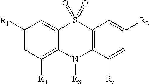
- the present disclosure provides a rechargeable battery comprising a positive electrode having a recharged potential, a negative electrode, a charge-carrying electrolyte, and an active material having the following structure:
- R 1 and R 2 are independently an alkyl group, a nitrile group, a haloalkyl group, a perhaloalkyl group, an acyl group, and acyloxy group, an acetyl group, a haloacetyl group, an alkylaryl group, an alkoxy group, an acetamido group, an amido group, an aryl group, an aralkyl group, an alkyl carboxyl group, an aryl carboxyl group, an alkylsulfonyl group, a benzoyl group, a carbamoyl group, a carboxy group, a cyano group, a formyl group, a halo group, a haloacetamido group, a haloacyl group, a haloalkylsulfonyl group, a haloaryl group, an arylhaloalkyl group, a methylsulfony
- R 3 is an alkyl group, a haloalkyl group, a perhaloalkyl group, an acyl group, and acyloxy group, an acetyl group, a haloacetyl group, an alkylaryl group, an alkoxy group, an acetamido group, an amido group, an aryl group, an aralkyl group, an alkyl carboxyl group, an aryl carboxyl group, an alkylsulfonyl group, a benzoyl group, a carbamoyl group, a carboxy group, a cyano group, a formyl group, a halo group, a haloacetamido group, a haloacyl group, a haloalkylsulfonyl group, a haloaryl group, an arylhaloalkyl group, a methylsulfonyloxyl group, a nitro group, an
- R 4 and R 5 are independently hydrogen, an alkyl group, a haloalkyl group, a perhaloalkyl group, an acyl group, and acyloxy group, an acetyl group, a haloacetyl group, an alkylaryl group, an alkoxy group, an acetamido group, an amido group, an aryl group, an aralkyl group, an alkyl carboxyl group, an aryl carboxyl group, an alkylsulfonyl group, a benzoyl group, a carbamoyl group, a carboxy group, a cyano group, a formyl group, a halo group, a haloacetamido group, a haloacyl group, a haloalkylsulfonyl group, a haloaryl group, an arylhaloalkyl group, a methylsulfonyloxyl group,
- the device may be a rechargeable lithium-ion cell (hereinafter described as a “cell”).
- the cell can alternatively be described as a battery, i.e., a rechargeable lithium-ion battery.
- the cell has a cell capacity, which is known in the art as an amount of electric charge the cell can deliver at a rated voltage.
- the capacity of the instant cell is not particularly limited and may be chosen by one of skill in the art.
- the device may be a redox flow battery.
- the device may be an electrochemical double layer capacitor, which may be described as a supercapacitor or ultracapacitor.
- the cell may be sealed in a suitable case, e.g., in mating cylindrical metal shells such as in a coin-type cell, in an elongated cylindrical AAA, AA, C, or D cell casing, or in a replaceable battery pack.
- the cell may be sealed in a Li-ion format such as in an 18650 format, in a pouch cell, etc.
- the cell may be used in a variety of devices, including portable computers, tablet displays, personal digital assistants, mobile telephones, motorized devices (e.g., personal or household appliances and vehicles), instruments, illumination devices (e.g., flashlights), and heating devices.
- the cell may have particular utility in low-cost mass market electrical and electronic devices such as flashlights, radios, compact disc (CD) players, and the like, which heretofore have usually been powered by non-rechargeable batteries such as alkaline cells.
- the cell includes a positive electrode having a recharged potential.
- the cell may have a single positive electrode or more than one positive electrode.
- the terminology “positive electrode” may describe one or a pair of electrodes that, under typical circumstances and when the cell is fully charged, will have the highest potential the electrode(s) can achieve under normal operation. The terminology also typically describes the same physical electrode under all cell operating conditions even if the electrode temporarily (e.g., due to cell overdischarge) is driven to or exhibits a potential less than that of another (e.g., negative) electrode.
- the positive electrode is not particularly limited and may be any known in the art.
- Non-limiting examples of the positive electrode may include FeS 2 , LiCoPO 4 , LiFePO 4 , Li 2 FeS 2 , Li 2 FeSiO 4 , LiMn 2 O 4 , LiMnPO 4 , LiNiPO 4 , LiV 3 O 8 , LiV 6 O 13 , LiVOPO 4 , Li 3 V 2 (PO 4 ) 3 , MnO 2 , MoS 3 , sulfur, TiS 2 , TiS 3 , V 2 O 5 , V 6 O 13 , LiCoO 2 , LiNiMnCoO 2 , LiNiCoAlO 2 , and/or combinations thereof.
- the positive electrode may include additives, e.g., carbon black, flake graphite, and the like.
- the positive electrode may be in any convenient form including foils, plates, rods, pastes, or as a composite made by forming a coating of the positive electrode material on a conductive current collector or other suitable support.
- the cell includes a negative electrode.
- the cell may have a single negative electrode or more than one negative electrode.
- the terminology “negative electrode” may describe one of a pair of electrodes that, under normal circumstances and when the cell is fully charged, has the lowest potential. This terminology also typically describes the same physical electrode under all cell operating conditions even if such electrode is temporarily (e.g., due to cell overdischarge) driven to or exhibits a potential above that of the other (e.g., positive) electrode.
- the negative electrode is not particularly limited and may be any known in the art.
- the negative electrode includes graphitic carbon, lithium metal, a lithium alloy, or combinations thereof.
- the negative electrode may include additives, e.g., carbon black.
- the negative electrode may be in any convenient form including foils, plates, rods, pastes, or as a composite made by forming a coating of the negative electrode material on a conductive current collector or other suitable support.
- the rechargeable lithium-ion cell also includes a charge-carrying electrolyte.
- the charge-carrying electrolyte includes a charge-carrying medium and a lithium salt.
- the charge-carrying electrolyte is not particularly limited and may be any known in the art.
- the charge-carrying electrolyte provides a charge-carrying pathway between the positive and negative electrodes, and initially includes at least the charge-carrying medium and the lithium salt.
- the charge-carrying electrolyte may include other additives typically utilized in the art.
- the charge-carrying electrolyte may be in any convenient form including liquids and gels.
- the charge-carrying electrolyte may include an active material, such as the redox shuttle (as described in detail below) that may or may not be dissolved therein.
- the charge-carrying electrolyte may be formulated without the redox shuttle and incorporated into a cell whose positive or negative electrode includes a dissolvable redox shuttle that can dissolve into the charge-carrying electrolyte after cell assembly or during the first charge-discharge cycle, so that the charge-carrying electrolyte includes a redox shuttle once the cell has been put into use.
- the charge-carrying electrolyte is not particularly limited and may be any known in the art.
- suitable charge-carrying mediums include liquids and gels capable of solubilizing sufficient quantities of lithium salt and the redox shuttle so that a suitable quantity of charge can be transported from the positive electrode to the negative electrode.
- the charge-carrying medium can typically be used over a wide temperature range, e.g., from about ⁇ 30° C. to about 70° C. without freezing or boiling, and is typically stable in the electrochemical window within which the electrodes operate.
- Non-limiting examples of charge-carrying mediums include, but are not limited to, ethylene carbonate, propylene carbonate, dimethyl carbonate, diethyl carbonate, ethylmethyl carbonate, butylene carbonate, vinylene carbonate, fluoroethylene carbonate, fluoropropylene carbonate, ⁇ -butyrolactone, methyl difluoroacetate, ethyl difluoroacetate, dimethoxyethane, diglyme (bis(2-methoxyethyl)ether), and combinations thereof.
- the charge-carrying medium includes ethylene carbonate, propylene carbonate, dimethyl carbonate, diethyl carbonate, ethylmethyl carbonate, and/or combinations thereof.
- the charge-carrying medium is typically present in an amount of from 60% to 99% by weight, from 65% to 95% by weight, or from 70% to 90% by weight, each based on a total weight of the charge-carrying electrolyte.
- all values and ranges of values within those values described above are hereby expressly contemplated in various non-limiting embodiments.
- the lithium salt is also not particularly limited and may include any known in the art.
- suitable lithium salts are stable and soluble in the chosen charge-carrying medium and perform well in the chosen lithium-ion cell, and can include or be LiPF 6 , LiBF 4 , LiClO 4 , lithium bis(oxalato)borate (“LiBOB”), LiN(CF 3 SO 2 ) 2 , LiN(C 2 F 5 SO 2 ) 2 , LiAsF 6 , LiC(CF 3 SO 2 ) 3 and/or combinations thereof.
- the lithium salt is typically present in an amount of from 1 to 40, from 5 to 35, or from 10 to 30, parts by weight per 100 parts by weight of the charge-carrying electrolyte.
- All values and ranges of values within those values described above are hereby expressly contemplated in various non-limiting embodiments.
- the cell includes a redox shuttle.
- the terminology “redox shuttle” describes an electrochemically reversible moiety or compound that can become oxidized at the positive electrode, migrate to the negative electrode, become reduced at the negative electrode to reform the unoxidized (or less-oxidized) shuttle species, and migrate back to the positive electrode.
- the redox shuttle may be described as an electroactive compound, which may be heterocyclic, wherein the terminology “electroactive” is as understood by those of skill in the art.
- any one or more of the substituted phenothiazine 5,5-dioxides described below may be described as a redox shuttle and/or a compound that protects against overcharging.
- a redox shuttle may have an oxidation potential above the recharged potential of the positive electrode and may serve as a cyclable redox shuttle providing cell overcharge protection.
- the terminology “oxidation potential” typically refers to a value E 1/2 which may be measured by dissolving the redox shuttle in the chosen charge-carrying electrolyte, measuring current versus applied voltage using cyclic voltammetry and a platinum or glassy carbon working electrode, a counter electrode and a suitable reference electrode that has been previously referenced to Li/Li + and determining the potentials E pa (i.e., the potential at which the peak anodic current is observed) and E pc (i.e., the potential at which the peak cathodic current is observed), relative to Li/Li + .
- E pa i.e., the potential at which the peak anodic current is observed
- E pc i.e., the potential at which the peak cathodic current is observed
- E 1/2 is typically taken as the average of E pa and E pc .
- Shuttle oxidation potentials may be estimated (to provide a value “E obs ”) by constructing a cell including the shuttle, carrying out a charge/discharge cycling test, and observing during a charging sequence the potential at which a voltage plateau indicative of shuttle oxidation and reduction occurs. The observed result may be corrected by the amount of the negative electrode potential vs. Li/Li + to provide an E obs value relative to Li/Li + .
- Shuttle oxidation potentials may be approximated (to provide a value “E calc ”) using modeling software such as GAUSSIAN 03 from Gaussian Inc. to predict oxidation potentials (e.g. for compounds whose D 1/2 is not known) by correlating model ionization potentials to the oxidation potentials and lithium-ion cell behavior of measured compounds.
- the redox shuttle may, for example, have an oxidation potential from 3.5 to 5, from 3.6 to 5, from 3.7 to 5, from 3.8 to 5, from 3.9 to 4.9, from 4 to 4.8, from 4.1 to 4.7, from 4.2 to 4.6, from 4.3 to 4.5, or from 4.4 to 4.5 V as compared to Li/Li + , above the recharged potential of the positive electrode.
- a redox shuttle has an oxidation potential from 3.5 to 5 V as compared to Li/Li + .
- the redox shuttle has an oxidation potential from 4 to 5 V as compared to Li/Li + .
- the redox shuttle has an oxidation potential from 3.5 to 4 V as compared to Li/Li + . In a further embodiment, the redox shuttle has an oxidation potential from 3.7 to 3.9 V as compared to Li/Li + , e.g. for LiFePO 4 cells. Alternatively, all values and ranges of values within those values described above are hereby expressly contemplated in various non-limiting embodiments.
- the redox shuttle may be disposed in a charge-carrying electrolyte and/or in another location in the cell.
- the oxidized redox shuttle carries a charge quantity corresponding to the applied charging current to the negative electrode, which prevents or at least minimizes cell overcharge.
- the redox shuttle is cyclable to provide at least 10, at least 30, at least 100, or at least 500 cycles of overcharge protection at a charging voltage sufficient to oxidize the redox shuttle and at an overcharge charge flow equivalent to 100% of the cell capacity during each cycle.
- the aforementioned number of cycles is 500-1000, greater than 1,000, from 1,000 to 10,000, or even greater than 10,000.
- the redox shuttle is different from the positive electrode and typically has an oxidation potential different from and/or higher (e.g. more positive) than the recharged potential of the positive electrode.
- the potential of the redox shuttle may be slightly greater than the recharged potential of the positive electrode, less than the potential at which irreversible cell damage might occur, and less than the potential at which excessive cell heating or outgassing may occur.
- the substituted phenothiazine 5,5-dioxide is utilized alone as a redox shuttle or in combination with other redox shuttles.
- Alternative redox shuttles include substituted carbazoles, substituted phenothiazines, substituted 5,10-dihydrophenazines, and/or combinations thereof.
- the substituted phenothiazine-5,5-dioxide typically has the following structure:
- R 1 and R 2 are independently an alkyl group, a nitrile group, a haloalkyl group, a perhaloalkyl group, an acyl group, and acyloxy group, an acetyl group, a haloacetyl group, an alkylaryl group, an alkoxy group, an acetamido group, an amido group, an aryl group, an aralkyl group, an alkyl carboxyl group, an aryl carboxyl group, an alkylsulfonyl group, a benzoyl group, a carbamoyl group, a carboxy group, a cyano group, a formyl group, a halo group, a haloacetamido group, a haloacyl group, a haloalkylsulfonyl group, a haloaryl group, an arylhaloalkyl group, a methyls
- R 3 is an alkyl group, a haloalkyl group, a perhaloalkyl group, an acyl group, and acyloxy group, an acetyl group, a haloacetyl group, an alkylaryl group, an alkoxy group, an acetamido group, an amido group, an aryl group, an aralkyl group, an alkyl carboxyl group, an aryl carboxyl group, an alkylsulfonyl group, a benzoyl group, a carbamoyl group, a carboxy group, a cyano group, a formyl group, a halo group, a haloacetamido group, a haloacyl group, a haloalkylsulfonyl group, a haloaryl group, an arylhaloalkyl group, a methylsulfonyloxyl group, a nitro group, an
- R 4 and R 5 are independently hydrogen, an alkyl group, a haloalkyl group, a perhaloalkyl group, an acyl group, and acyloxy group, an acetyl group, a haloacetyl group, an alkylaryl group, an alkoxy group, an acetamido group, an amido group, an aryl group, an aralkyl group, an alkyl carboxyl group, an aryl carboxyl group, an alkylsulfonyl group, a benzoyl group, a carbamoyl group, a carboxy group, a cyano group, a formyl group, a halo group, a haloacetamido group, a haloacyl group, a haloalkylsulfonyl group, a haloaryl group, an arylhaloalkyl group, a methylsulfonyloxyl group,
- R 4 and R 5 are not a hydrogen atom
- R 1 and R 2 are independently an alkyl group, a nitrile group, a haloalkyl group (e.g. mono-, di-, or tri-halo), a perhaloalkyl group, an acyl group, an acyloxy group, an acetyl group, a haloacetyl group, an alkaryl group, an alkoxy group, an acetamido group, an amido group, an aryl group, an aralkyl group, an alkyl carboxyl group, an aryl carboxyl group, an alkylsulfonyl group, a benzoyl group, a carbamoyl group, a carboxy group, a cyano group, a formyl group, a halo group, a haloacetamido group, a haloacyl group, a haloalkylsulfonyl group, a haloaryl group,
- R 3 is an alkyl group having 1-6 carbon atoms or 1-12 carbon atoms or a haloalkyl group (e.g., mono-, di-, or tri-halo) having 1-12 carbon atoms.
- both of R 4 and R 5 is hydrogen.
- one of R 4 and R 5 is a hydrogen atom, whereas the other of R 4 and R 5 is not a hydrogen atom.
- R 3 is an alkyl group having 1, 2, 3, 4, 5, or 6 carbon atoms or 1-12 carbon atoms, a haloalkyl group (e.g.
- R 1 and R 2 are independently an alkyl group having 1, 2, 3, 4, 5, or 6 carbon atoms or 1-12 carbon atoms, a trifluoromethyl group, a halo group, a cyano group, an alkyl ether group having 1 to 12 carbon atoms, an alkyl ether group having 1-12 carbon atoms, or a trialkylammoniumalkyl group having 1 to 12 carbon atoms.
- R 4 and R 5 are independently an alkyl group having 1, 2, 3, 4, 5, or 6 carbon atoms or 1-12 carbon atoms, a haloalkyl group (e.g.
- Suitable alkyl groups are methyl, ethyl, propyl, iso-propyl, butyl, iso-butyl, sec-butyl, tert-butyl, neopentyl, n-pentyl, hexyl, octyl, and the like, as appreciated by those of skill in the art.
- all values and ranges of values within those values described above are hereby expressly contemplated in various non-limiting embodiments.
- one of R 4 and R 5 is sterically bulky.
- each of R 4 and R 5 is sterically bulky.
- the terminology “sterically bulky” is appreciated by those of skill in the art.
- one or each of R 4 and R 5 may be C 2 -C 4 alkyl group, such as an iso-propyl, butyl, iso-butyl, sec-butyl, tert-butyl group.
- These types of groups may shift a potential to a more positive value without sacrificing (or at least minimizing an effect on) stability of the compound. In some instances, these types of groups may actually enhance stability of the compound.
- R 4 and R 5 may be a C 2 -C 5 alkyl group and may include those groups described above and neopentyl groups.
- each of R 4 and R 5 may be methyl and/or CF 3 groups.
- R 1 and R 2 are independently an alkyl group, a haloalkyl group (including perhaloalkyl), or an alkyl ether group and at least one of R 3 , R 4 , and R 5 is an alkyl group, a haloalkyl group (including perhaloalkyl), an alkyl ether group, an acyl group, or a haloacyl group.
- each of R 1 , R 2 , R 3 , R 4 , and R 5 are chosen from alkyl groups, alkyl ether groups, acetyl groups, and CF 3 groups. Without intending to be bound by any particular theory, it is believed that substitution at some of these positions (such as, e.g., at R 3 , R 4 and/or R 5 ) surprisingly increases the oxidation potential through a steric effect.
- R 1 and R 2 are independently an alkyl group or a nitrile group.
- R 3 is an alkyl group, a haloalkyl group, a perhaloalkyl group, an acyl group, and acyloxy group, an acetyl group, a haloacetyl group, an alkylaryl group, an alkoxy group, an acetamido group, an amido group, an aryl group, an aralkyl group, an alkyl carboxyl group, an aryl carboxyl group, an alkylsulfonyl group, a benzoyl group, a carbamoyl group, a carboxy group, a cyano group, a formyl group, a halo group, a haloacetamido group, a haloacyl group, a haloalkylsulfonyl group, a haloaryl group, an arylhaloal
- R 4 and R 5 are independently hydrogen, an alkyl group, a haloalkyl group, a perhaloalkyl group, an acyl group, and acyloxy group, an acetyl group, a haloacetyl group, an alkylaryl group, an alkoxy group, an acetamido group, an amido group, an aryl group, an aralkyl group, an alkyl carboxyl group, an aryl carboxyl group, an alkylsulfonyl group, a benzoyl group, a carbamoyl group, a carboxy group, a cyano group, a formyl group, a halo group, a haloacetamido group, a haloacyl group, a haloalkylsulfonyl group, a haloaryl group, an arylhaloalkyl group, a methylsulfonyloxyl group,
- R 3 is chosen from —CH 2 CH 3 , —CH 2 CH 2 OCH 2 CH 2 OCH 3 , —CH 2 CH 2 OCH 3 , and -phenyl-N(CH 3 ) 3+ .
- R 3 may be any one of these moieties.
- compounds having one of these R 3 moieties may have an oxidation potential of 4.26 to 4.40 V.
- such compound may have increased solubility in at least high lithium content carbonate electrolytes.
- the redox shuttle e.g. the substituted phenothiazine-5,5-dioxide
- the substituted phenothiazine-5,5-dioxide is present in an amount of from 0.05 to 20, from 0.05 to 10, from 1 to 10, from 2 to 9, from 3 to 8, from 4 to 7, or from 5 to 6, parts by weight per 100 parts by weight of the charge-carrying electrolyte.
- Amounts of the substituted phenothiazine-5,5-dioxide may be chosen based on solubility, diffusion coefficients, the need for overcharge protection, etc.
- Mixtures of two or more redox shuttles including the phenothiazine-5,5-dioxide and one or more substituted phenothiazines, substituted carbazoles, substituted dihydrophenazines, or other redox shuttle) having different electrochemical potentials vs. Li/Li + may also be employed.
- a first redox shuttle operative at 3.7 V and a second redox shuttle operative at 3.9 V may both be employed in a single cell.
- the second redox shuttle (which typically would not have been oxidized while the first redox shuttle was operative) can take over and provide a further (albeit higher E 1/2 ) margin of safety against overcharge damage.
- the redox shuttle can also provide overdischarge protection to a cell or to a battery of series-connected cells.
- Redox shuttles can also be used for cell balancing purposes as well as or even in lieu of overcharge protection. For example, redox shuttles could be used to reduce the cost of cell-balancing associated electronics.
- the redox shuttle can be dissolved or is dissolvable in the charge-carrying electrolyte in an amount sufficient to provide overcharge protection at the intended charging rate.
- the charge-carrying electrolyte promotes a large diffusion constant D to the redox shuttle and/or supports a high redox shuttle concentration C. Accordingly, the charge-carrying electrolyte initially or eventually includes a dissolved quantity of the substituted phenothiazine 5,5-dioxide and/or other redox shuttles.
- the redox shuttle diffusion constant D typically increases as the viscosity of the charge-carrying electrolyte decreases.
- Non-limiting concentrations of the substituted phenothiazine 5,5-dioxide and/or other redox shuttle in the charge-carrying electrolyte are about 0.02 M up to a limit of solubility, about 0.05 M up to a limit of solubility, more than 0.1 M up to a limit of solubility, about 0.2 M up to a limit of solubility or about 0.3 M up to a limit of solubility.
- the concentration of the substituted phenothiazine 5,5-dioxide and/or other redox shuttle may be increased by incorporating a suitable co-solvent in the charge-carrying electrolyte.
- Non-limiting co-solvents include acetonitrile, benzene, ethers, esters, lactones, pyridine, tetrahydrofuran, toluene, and/or combinations thereof.
- the co-solvent is chosen from ethylene carbonate, propylene carbonate, dimethyl carbonate, diethyl carbonate, ethylmethyl carbonate, butylene carbonate, vinylene carbonate, fluoroethylene carbonate, fluoropropylene carbonate, ⁇ -butyrolactone, methyl difluoroacetate, ethyl difluoroacetate, dimethoxyethane, diglyme (bis(2-methoxyethyl)ether), and combinations thereof.
- the co-solvent is chosen from ethylene carbonate, propylene carbonate, dimethyl carbonate, diethyl carbonate, ethylmethyl carbonate, and/or combinations thereof.
- the redox-shuttle may be 3,7-bis(tert-butyl)-10-methylphenothiazine-5,5-dioxide; 3,7-bis(tert-butyl)-10-(p-tolyl)-phenothiazine-5,5-dioxide; 3,7-bis(tert-butyl)-10-(9-trifluoromethylphenyl)-phenothiazine-5,5-dioxide; or other phenothiazine-5,5-dioxides analogous to the aforementioned compounds; and/or any analogs having substitution at any position such as C 1 -C 20 alkyl, alkyl ether or oligoether, trialkylammoniumalkyl, or other solubilizing groups.
- the solubilizing group may be any known in the art.
- the solubilizing groups may be as described in U.S. Pat. No. 6,445,486, which is expressly incorporated herein by reference in various non-limiting embodiments.
- any compounds described in the Examples below may be utilized in any embodiments described herein in various non-limiting embodiments.
- the cell may also include a porous cell separator disposed between the positive and negative electrodes and through which charge-carrying species (including the oxidized or reduced substituted phenothiazine-5,5-dioxide) may pass.
- charge-carrying species including the oxidized or reduced substituted phenothiazine-5,5-dioxide
- the redox shuttle provides overcharge protection to the cell after at least 30, 40, 50, 60, 70, 80, 90, 100, 200, 300, 400, 500, 600, 700, 800, 900, 1,000, 1,500, 2,000, 2,500, 3,000, 3,500, 4,000, 4,500, 5,000, 5,500, 6,000, 6,500, 7,000, 7,500, 8,000, 8,500, 9,000, 9,500, 10,000, or even greater, charge-discharge cycles at a charging voltage sufficient to oxidize the redox shuttle and at an overcharge charge flow equivalent to 100% of the cell capacity during each charge-discharge cycle.
- all values and ranges of values within those values described above are hereby expressly contemplated in various non-limiting embodiments.
- This disclosure also provides an article including the cell and an array of cells.
- the article may be any known in the art that utilizes cells (or batteries), e.g. hand-held devices, flashlights, power tools, or any of those described above.
- the array of cells may also be any known in the art.
- the redox shuttle may also be used as an active catholyte material in redox flow batteries.
- Redox flow batteries include an electrochemical cell containing at least two electrodes and at least two electroactive materials. At least one of the electroactive materials is in the form of an electrolyte solution or slurry, including the electroactive material, a suitable solvent, and optionally an added electrolyte salt for improved ionic conductivity.
- the electrolyte solution may be moved from a separate tank through a cell using a pump, gravity, pressure, or other suitable means.
- the electrochemical cell may be divided into an anode and a cathode chamber by an ion exchange or microporous membrane that serves to minimize mixing of the different electroactive materials (often described as “crossover”).
- the electrochemical cell may be a membrane-free system that can maintain separation of the active species by laminar flow. Transport of the electrolyte salt anion and/or cation across the membrane can occur, which facilitates an electrochemical reaction between the electroactive materials (provided that the electrodes are connected by an external electrical circuit).
- multiple electrochemical cells can be connected in series or in parallel to form a cell stack for producing a desired level of current and/or voltage.
- Redox flow batteries typically utilize solution phase materials in both the anode and cathode compartments (which are often described as “anolyte” and “catholyte”, respectively).
- redox flow batteries may utilize an intercalation-type electrode, such as graphite or the like, as the anode or cathode.
- the electroactive materials for the redox flow battery are typically stored in a tank or other suitable container outside of the electrochemical cell, power and energy are effectively decoupled and energy storage can be readily and inexpensively scaled. While the energy density of the redox flow battery is generally too low for mobile applications, the potential low cost and scalability renders the redox flow battery as being well suited for grid or energy storage applications.
- Embodiments of the redox shuttle described in detail above may be used as a redox active or catholyte material for a redox flow battery, at least in part because the redox shuttle has one or more of a low manufacturing cost, a high solubility, a rapid electrochemical response, a high oxidation potential, and excellent durability.
- the catholyte material is present in an amount of from about 2 to 80 parts by weight per 100 parts by weight of the charge-carrying electrolyte.
- 3,7-bis(tert-butyl)-10-methylphenothiazine-5,5-dioxide may be used as a catholyte material, may be readily prepared from inexpensive materials, is soluble in propylene carbonate to over 1.4 M, exhibits a desirable electrochemical oxidation at 4.28V as compared to Li/Li + , and is stable in both the neutral and oxidized form.
- the redox shuttle may be used as an active catholyte material in electrochemical double layer (EDL) capacitors, which are often also described as supercapacitors or ultracapacitors.
- EDL capacitors differ from batteries in that the electrical energy is stored by the physical process of building charge on the surface of inert electrodes rather than storing energy in an electrochemical reaction (as in batteries).
- the electrical current that serves to build charge on the surface of an electrode may be described as capacitive or nonfaradaic current.
- Current that serves to carry out a chemical reaction may be described as faradaic current or, with electrochemical reactions within an EDL capacitor, pseudocapacitance.
- Hybrid supercapacitors are devices that combine the properties of batteries and EDL capacitors, and can store electrical energy in both faradaic and nonfaradaic processes.
- a common type of hybrid supercapacitor is an EDL capacitor with the charge storage capability enhanced by incorporating a redox active material in the electrolyte.
- Embodiments of the redox shuttle described in detail above may also be used as the redox active material for EDL capacitors, particularly hybrid supercapacitors, at least in part because the redox shuttle has one or more of a low manufacturing cost, a high solubility, a rapid electrochemical response, a high oxidation potential, and excellent durability.
- this disclosure provides a redox shuttle for a lithium-ion cell having the following structure:
- R 1 and R 2 are independently an alkyl group, a nitrile group, a haloalkyl group, a perhaloalkyl group, an acyl group, and acyloxy group, an acetyl group, a haloacetyl group, an alkylaryl group, an alkoxy group, an acetamido group, an amido group, an aryl group, an aralkyl group, an alkyl carboxyl group, an aryl carboxyl group, an alkylsulfonyl group, a benzoyl group, a carbamoyl group, a carboxy group, a cyano group, a formyl group, a halo group, a haloacetamido group, a haloacyl group, a haloalkylsulfonyl group, a haloaryl group, an arylhaloalkyl group, a methylsulfony
- R 3 is an alkyl group, a haloalkyl group, a perhaloalkyl group, an acyl group, and acyloxy group, an acetyl group, a haloacetyl group, an alkylaryl group, an alkoxy group, an acetamido group, an amido group, an aryl group, an aralkyl group, an alkyl carboxyl group, an aryl carboxyl group, an alkylsulfonyl group, a benzoyl group, a carbamoyl group, a carboxy group, a cyano group, a formyl group, a halo group, a haloacetamido group, a haloacyl group, a haloalkylsulfonyl group, a haloaryl group, an arylhaloalkyl group, a methylsulfonyloxyl group, a nitro group, an
- R 4 and R 5 are independently hydrogen, an alkyl group, a haloalkyl group, a perhaloalkyl group, an acyl group, and acyloxy group, an acetyl group, a haloacetyl group, an alkylaryl group, an alkoxy group, an acetamido group, an amido group, an aryl group, an aralkyl group, an alkyl carboxyl group, an aryl carboxyl group, an alkylsulfonyl group, a benzoyl group, a carbamoyl group, a carboxy group, a cyano group, a formyl group, a halo group, a haloacetamido group, a haloacyl group, a haloalkylsulfonyl group, a haloaryl group, an arylhaloalkyl group, a methylsulfonyloxyl group,
- this disclosure provides a catholyte material for a redox flow battery having the following structure:
- R 1 and R 2 are independently an alkyl group, a nitrile group, a haloalkyl group, a perhaloalkyl group, an acyl group, and acyloxy group, an acetyl group, a haloacetyl group, an alkylaryl group, an alkoxy group, an acetamido group, an amido group, an aryl group, an aralkyl group, an alkyl carboxyl group, an aryl carboxyl group, an alkylsulfonyl group, a benzoyl group, a carbamoyl group, a carboxy group, a cyano group, a formyl group, a halo group, a haloacetamido group, a haloacyl group, a haloalkylsulfonyl group, a haloaryl group, an arylhaloalkyl group, a methylsulfony
- R 3 is an alkyl group, a haloalkyl group, a perhaloalkyl group, an acyl group, and acyloxy group, an acetyl group, a haloacetyl group, an alkylaryl group, an alkoxy group, an acetamido group, an amido group, an aryl group, an aralkyl group, an alkyl carboxyl group, an aryl carboxyl group, an alkylsulfonyl group, a benzoyl group, a carbamoyl group, a carboxy group, a cyano group, a formyl group, a halo group, a haloacetamido group, a haloacyl group, a haloalkylsulfonyl group, a haloaryl group, an arylhaloalkyl group, a methylsulfonyloxyl group, a nitro group, an
- R 4 and R 5 are independently hydrogen, an alkyl group, a haloalkyl group, a perhaloalkyl group, an acyl group, and acyloxy group, an acetyl group, a haloacetyl group, an alkylaryl group, an alkoxy group, an acetamido group, an amido group, an aryl group, an aralkyl group, an alkyl carboxyl group, an aryl carboxyl group, an alkylsulfonyl group, a benzoyl group, a carbamoyl group, a carboxy group, a cyano group, a formyl group, a halo group, a haloacetamido group, a haloacyl group, a haloalkylsulfonyl group, a haloaryl group, an arylhaloalkyl group, a methylsulfonyloxyl group,
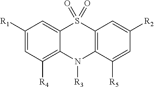
- this disclosure provides a phenothiazine-5,5-dioxide having the following structure:
- R 1 and R 2 are independently an alkyl group or a nitrile group
- R 3 is an alkyl group, a haloalkyl group, a perhaloalkyl group, an acyl group, and acyloxy group, an acetyl group, a haloacetyl group, an alkylaryl group, an alkoxy group, an acetamido group, an amido group, an aryl group, an aralkyl group, an alkyl carboxyl group, an aryl carboxyl group, an alkylsulfonyl group, a benzoyl group, a carbamoyl group, a carboxy group, a cyano group, a formyl group, a halo group, a haloacetamido group, a haloacyl group, a haloalkylsulfonyl group, a haloaryl group, an arylhaloalkyl group, a methylsulfonyloxyl group, a nitro group, an
- R 4 and R 5 are independently hydrogen, an alkyl group, a haloalkyl group, a perhaloalkyl group, an acyl group, and acyloxy group, an acetyl group, a haloacetyl group, an alkylaryl group, an alkoxy group, an acetamido group, an amido group, an aryl group, an aralkyl group, an alkyl carboxyl group, an aryl carboxyl group, an alkylsulfonyl group, a benzoyl group, a carbamoyl group, a carboxyl group, a haloalkylsulfonyl group, a haloaryl group, an arylhaloalkyl group, a methylsulfonyloxyl group, a nitro group, an alkyl ether group, a haloalkylether group, a trialkylammoniumalkyl group, a phosphat
- the oxidation potential E 0 of a redox shuttle candidate relative to a lithium-ion cell can be determined by comparing the difference in standard free energies between the B3LYP energy G 0 (in electronvolts) between the shuttle S and its radical cation S + :
- the phenothiazine-5,5-dioxides are generally prepared by preparing a phenothiazine including the R 1 and R 2 groups and optionally including the R 4 and R 5 groups, then attaching the R 3 group, and then oxidizing to form a dioxide.
- the R 4 and R 5 groups are attached early, e.g. when forming the ring.
- the R 4 and R 5 groups may be attached late, e.g. after attaching the R 3 group and before oxidation.
- Specific examples of precursors for forming phenothiazine-5,5-dioxides, as well as specific examples of phenothiazine-5,5-dioxides are described below.
- the precursor 3,7-bis-tert-butylphenothiazine is prepared according to the following synthesis.
- About 10 g (50.25 mmol, 1 eq) of phenothiazine and about 9 g (67.5 mmol, 1.3 eq) of aluminum chloride are placed in a round bottom flask.
- About 120 mL of dichloromethane is added and the reacted mixture (or reaction) is placed in a water/ice bath.
- About 27.3 mL (251.16 mmol, 5 eq) of tert-butyl chloride are added dropwise. After the addition is complete, the reacted mixture is left stirring at 0-5° C.
- the precursor 3,7-bis-tert-butylphenothiazine may be used to prepare the following 10-substituted 3,7-bis-tert-butylphenothiazines: 3,7-bis(tert-butyl)-10-methylphenothiazine; 3,7-bis(tert-butyl)-10-(p-tolyl)phenothiazine; 3,7-bis(tert-butyl)-10-(p-trifluoromethylphenyl)phenothiazine; 3,7-bis(tert-butyl)-10-(p-nitrophenyl)phenothiazine; and 3,7-bis(tert-butyl)-10-(3-bromopropyl)phenothiazine.
- 3,7-bis(tert-butyl)-10-methylphenothiazine is prepared according to the following synthesis.
- About 200 mL of acetonitrile and about 4.4 mL (70.7 mmol, 2.2 eq) are added.
- the reacted mixture (i.e., the reaction) is heated to reflux and left overnight. Then, the reaction is cooled to room temperature and about 200 mL of water is added, which crashes out the product. The reaction is filtered by gravity filtration, to produce about 9.21 g (88% yield) of 3,7-bis(tert-butyl)-10-methylphenothiazine.
- 3,7-bis(tert-butyl)-10-(p-tolyl)phenothiazine is prepared according to the following synthesis.
- 4-iodobenzene (0.79 g, 3.62 mmol, 1.2 eq) is melted in a round bottom flask.
- About 1.3 g (9.4 mmol, 3 eq) of potassium carbonate and about 1 g (3.21 mmol, 1 eq) of 3,7-bis-tert-butylphenothiazine, and some copper powder is added.
- the reacted mixture is cooled and dried via rotary evaporation. The remainder is dissolved in ethanol and filtered.
- 3,7-bis(tert-butyl)-10-(p-trifluoromethylphenyl)phenothiazine is prepared according to the following synthesis.
- 3,7-bis-t-butyl phenothiazine (5 g, 0.016 mol) is dissolved under stirring in about 50 mL N-methylpyrrolidinone (NMP) in a glove box under a nitrogen atmosphere.
- NaH as a 60% wt. suspension in mineral oil (1.0 g, 0.024 mol, 1.5 eq) is added at once, and the reaction mixture is stirred for about 60 minutes to form an orange suspension.
- 1-fluoro-4-trifluoromethylbenzene (5 mL, 0.040 mol, 2.5 eq) is added to the reaction mixture dropwise, and the flask is then transferred in the hood into an oil bath and pre-heated at about 80° C. The reaction is continued at the foregoing temperature for about 5 hours until a small sample analyzed by thin layer chromatography (eluent: hexane/ethylacetate: 8/2) indicates the completion of the reaction. The flask is then transferred into a water-ice bath, cooled to 0-5° C. and diluted with about 100 mL deionized water under vigorous stirring.
- the orange emulsion formed is extracted with about 3 ⁇ 100 mL dichloromethane, and the combined organic phase is washed with about 3 ⁇ 100 mL water and about 1 ⁇ 50 mL brine. After drying the dichloromethane solution over MgSO 4 , (5 g), the solvent is evaporated under reduced pressure and the orange crystals are washed with about 25 mL cold methanol and about 25 mL cold hexane. After traces of solvents are removed by drying the product in a vacuum oven at room temperature for 12 hours, 6.3 g (yield: 86.3%) of pale yellow crystals (3,7-bis(tert-butyl)-10-(p-trifluoromethylphenyl)phenothiazine) are obtained.
- 3,7-bis(tert-butyl)-N-nitrophenylphenothiazine is prepared according to the following synthesis.
- 3,7-bis-tert-butylphenothiazine (2 g, 6.43 mmol, 1 eq) is dissolved in about 30 mL of dry tetrahydrofuran and about 0.77 g NaH, 60% dispersion in mineral oil (19.25 mmol, 3 eq).
- About 2.82 g of p-nitrofluorobenzene (19.98 mmol, 3 eq) is added.
- the reaction mixture is put under N 2 , stirred overnight, and then washed with water and the tetrahydrofuran is removed via rotary evaporation.
- the synthesis produced about 2.55 g (92% yield) of 3,7-bis(tert-butyl)-N-nitrophenylphenothiazine.
- 3,7-bis(tert-butyl)-10-(3-bromopropyl)phenothiazine is produced according to the following synthesis.
- a 100 ml flask is charged with about 4.7 g of phenothiazine, about 0.78 g of sodium dithionite, about 2.6 g of sodium carbonate, about 0.52 g of methyltributylammonium chloride, and about 30 mL of acetonitrile.
- the combination is allowed to stir, and about 17 mL of 1,3-dibromopropane is added.
- the reaction mixture is heated to reflux and allowed to stir for about 44 hours.
- reaction mixture is then quenched with water, and the desired product is extracted with about 600 mL of dichloromethane (100 mL washes).
- the organic washes are dried over MgSO 4 , and the dichloromethane is removed by rotary evaporation, resulting in an amber-brown colored liquid.
- the reaction mixture is further purified by adding the reaction mixture to about 50 mL of acetonitrile and about 50 mL of hexane in a separatory funnel.
- the hexane layer is washed with about 3 ⁇ 50 mL of acetonitrile, and the hexane is removed by rotary evaporation to give a slightly tan clear oil.
- the oil is dried in a vacuum oven to yield about 2.14 g of substantially pure 3,7-bis(tert-butyl)-10-(3-bromopropyl)phenothiazine.
- the 3,7-bis-tert-butylphenothiazine-5,5-dioxides are generally prepared according to the following synthesis.
- One equivalent of 3,7-bis(tert-butyl)-10-substituted phenothiazine is dissolved in 2:1 dichloromethane:acetic acid, and about 2.5 equivalents of H 2 O 2 is added.
- the reaction mixture is heated to reflux overnight, then quenched with water, dried over MgSO 4 , and further dried via rotary evaporation.
- the reaction mixture is then triturated in water.
- the synthesis typically produced approximately 50% of the desired 3,7-bis-tert-butyl-10-substituted phenothiazine-5,5-dioxide.
- the MgSO 4 is filtered off and the solvent is removed by rotary evaporation to give a thick white solid.
- the solid is dried in a vacuum oven for at least three hours to produce (yield) about 1.9 g, approximately 80%, of 3,7-bis(tert-butyl)-10-(3-bromopropyl)phenothiazine-5,5-dioxide.
- 3,7-bis-t-butyl-10-(p-trifluoromethylphenyl)phenothiazine-5,5-dioxide is prepared according to the following synthesis. 3,7-bis-t-butyl-10-(p-trifluoromethylphenyl)phenothiazine (2.5 g, 5.4 mmol) is added to a mixture of acetic acid (12.5 mL) and acetic anhydride (25 mL) to form a pink suspension. The pink suspension is vigorously stirred at room temperature for about 5 minutes.
- a 30% aqueous solution of H 2 O 2 (2.7 g, 32.92 mmol, 6 eq) is added at once, and the flask is transferred into an oil bath pre-heated at 65° C. Within about 5 minutes, a violet solution is formed and after another 5 minutes, the color of the solution turns to a pale yellow. During the next 30 minutes, a white solid separates and the flask is transferred to a water bath and cooled to room temperature. The white crystals are filtered, washed with about 3 ⁇ 50 mL deionized water, and dried at room temperature under reduced pressure. The amount of white crystals recovered is about 1.4 g.
- the filtrate is added dropwise, using a dropping funnel, into 500 mL deionized water when a milk-like suspension is obtained.
- the slurry is filtrated, washed with water, and then dried.
- the synthesis produced (yield) about 1 g, 89.69%, of 3,7-bis-t-butyl-10-(p-trifluoromethylphenyl)phenothiazine-5,5-dioxide.
- Additional compounds are also synthesized, as set forth below. More specifically, the synthesis of three intermediates is described followed by the synthesis of various embodiments of phenothiazine-5,5-dioxides. These compounds, as set forth in the table below, are evaluated in the same way as is described above.
- 3,7-Di-t-butyl phenothiazine (5 g, 16.05 mmol) was dissolved under stirring in 50 mL NMP, in a 250-mL round bottomed, 2-necked flask fitted with septa, in the glove box. NaH as a 60% wt. suspension in mineral oil (1.3 g, 32.1 mmol, 2 eq) was added at once and the reaction mixture was stirred for 30 minutes. 2-Methoxyethoxyethyl tosylate (5.5 g, 20.06 mmol, 1.25 eq) was dissolved in 10 mL NMP and added to the reaction mixture and the stirring was continued for 10 more minutes.
- the flask was then transferred into an oil bath pre-heated at 60° C., in the hood.
- a nitrogen flow was added via a syringe needle through one septum, with a short needle inserted as well, as a bleed point in another septum.
- the mixture was stirred for 5 hours at 60° C., and then allowed to cool to room temperature.
- the flask was next transferred into a water-ice bath, and the reaction mixture was cooled to 0-5° C. and diluted with 200 mL deionized water under vigorous stirring.
- the yellow emulsion that formed was extracted with 3 ⁇ 100 mL hexanes and combined hexanes solution was washed with 3 ⁇ 150 mL water and 1 ⁇ 150 mL brine. After drying the hexanes solution on MgSO 4 , the solvent was evaporated under reduced pressure to give 16.69 g of crude product, as yellow oil.
- the crude material was purified by column chromatography using as eluent a mixture of hexanes and ethyl acetate (80/20, v/v). The amount of product recovered after column: 15 g of colorless viscous oil (yield: 100%).
- reaction mixture was added dropwise, using a dropping funnel, into 500 mL deionized water and the emulsion formed was extracted with 3 ⁇ 100 mL ethyl acetate.
- the combined ethyl acetate solution was washed with 2 ⁇ 150 mL water, 2 ⁇ 100 mL 10 wt. % Na 2 CO 3 , and finally 2 ⁇ 150 mL water, dried over 5 g of MgSO 4 and the solvent was removed by rotary evaporation at reduced pressure to afford 5.1 g of pale yellow crude product.
- 3,7-Di-t-butyl phenothiazine (10 g, 32.1 mmol) was dissolved under stirring in 100 mL NMP, in a 500-mL round bottomed, 3-necked flask fitted with septa, in the glove box.
- NaH as a 60% wt. suspension in mineral oil (2 g, 48.2 mmol, 1.5 eq) was added at once and the reaction mixture was stirred for 60 minutes.
- 2-Bromoethyl methyl ether (6.7 g, 48.2 mmol, 1.5 eq) was dissolved in 10 mL NMP and added to the reaction mixture dropwise and the stirring was continued for 10 more minutes.
- the flask was then transferred into an oil bath pre-heated at 60° C., in the hood.
- a nitrogen flow was added via a syringe needle through one septum, with a short needle inserted as well, as a bleed point in another septum.
- the mixture was stirred for 1 hour at 60° C., and then allowed to cool to room temperature and stirred overnight.
- the crude reaction mixture was then quenched in 500 mL deionized water, under vigorous stirring.
- the milky emulsion that formed was extracted with 3 ⁇ 150 mL hexanes and combined hexanes solution was washed with 4 ⁇ 150 mL water and 1 ⁇ 150 mL brine.
- the reaction mixture was added dropwise, using a dropping funnel, into 500 mL deionized (DI) water and the emulsion formed was extracted with 3 ⁇ 100 mL ethyl acetate.
- DI deionized
- the combined ethyl acetate solution was washed with 2 ⁇ 150 mL water, 2 ⁇ 100 mL 10 wt. % Na 2 CO 3 , and finally 2 ⁇ 150 mL water, dried over 5 g of MgSO 4 and the solvent was removed by rotary evaporation at reduced pressure to afford 5.1 g of pale yellow solid product.
- 3,7-Di-t-butyl phenothiazine 14 g, 45 mmol was dissolved under stirring in 100 mL NMP, in a 250-mL round bottomed, 2-necked flask fitted with septa, in the glove box.
- NaH as a 60% wt. suspension in mineral oil (2.7 g, 67.5 mmol, 1.5 eq) was added at once and the reaction mixture was stirred for 60 minutes at room temperature.
- Ethyl iodide 14 g, 90 mmol, 2 eq was dissolved in 10 mL NMP and added to the reaction mixture dropwise.
- any ranges and subranges relied upon in describing various embodiments of the present disclosure independently and collectively fall within the scope of the appended claims and are understood to describe and contemplate all ranges, including whole and/or fractional values therein, even if such values are not expressly written herein.
- One of skill in the art readily recognizes that the enumerated ranges and subranges sufficiently describe and enable various embodiments of the present disclosure and such ranges and subranges may be further delineated into relevant halves, thirds, quarters, fifths, and so on.
- a range “of from 0.1 to 0.9” may be further delineated into a lower third, i.e., from 0.1 to 0.3, a middle third, i.e., from 0.4 to 0.6, and an upper third, i.e., from 0.7 to 0.9, which individually and collectively are within the scope of the appended claims and may be relied upon individually and/or collectively and provide adequate support for specific embodiments within the scope of the appended claims.
- a range such as “at least,” “greater than,” “less than,” “no more than,” and the like, it is to be understood that such language includes subranges and/or an upper or lower limit.
- a range of “at least 10” inherently includes a subrange of from at least 10 to 35, a subrange of from at least 10 to 25, a subrange from 25 to 35, and so on, and each subrange may be relied upon individually and/or collectively and provides adequate support for specific embodiments within the scope of the appended claims.
- an individual number within a disclosed range may be relied upon and provides adequate support for specific embodiments within the scope of the appended claims.
- a range “of from 1 to 9” includes various individual integers, such as 3, as well as individual numbers including a decimal point (or fraction), such as 4.1, which may be relied upon and provide adequate support for specific embodiments within the scope of the appended claims.
Landscapes
- Chemical & Material Sciences (AREA)
- Engineering & Computer Science (AREA)
- Chemical Kinetics & Catalysis (AREA)
- Electrochemistry (AREA)
- Power Engineering (AREA)
- Manufacturing & Machinery (AREA)
- General Chemical & Material Sciences (AREA)
- Microelectronics & Electronic Packaging (AREA)
- Organic Chemistry (AREA)
- Sustainable Development (AREA)
- Sustainable Energy (AREA)
- Physics & Mathematics (AREA)
- Condensed Matter Physics & Semiconductors (AREA)
- General Physics & Mathematics (AREA)
- Inorganic Chemistry (AREA)
- Life Sciences & Earth Sciences (AREA)
- Materials Engineering (AREA)
- Secondary Cells (AREA)
- Electric Double-Layer Capacitors Or The Like (AREA)
- Battery Electrode And Active Subsutance (AREA)
Abstract
Description

- The terminology “recharged potential” typically describes a value Ecp measured relative to Li/Li+ by constructing a cell including the positive electrode, a negative electrode, a charge-carrying electrolyte, and no redox shuttle, carrying out a charge/discharge cycling test and observing the potential at which the positive electrode become delithiated during the first charge cycle to a lithium level corresponding to at least 90% of the available recharged cell capacity. For some positive electrodes (e.g., LiFePO4), this lithium level may correspond to approximately complete delithiation (e.g., to Li0FePO4). For other positive electrodes (e.g., some electrodes having a layered lithium-including structure), this lithium level may correspond to partial delithiation.
Negative Electrode:

I max =FADC/d.

wherein:

wherein:

wherein:
 |
| R1 and R2 | R3 | R4 and R5 | E calc (Li/Li+) | E exp (Li/Li+) |
| t-Bu | CH3 | H | 4.27 | 4.28 |
| t-Bu | BrCH2CH2CH2 | H | 4.19 | 4.31 |
| t-Bu | 4-CH3-phenyl | H | 4.07 | 4.30 |
| t-Bu | 4-CF3-phenyl | H | 4.14 | 4.36 |
| t-Bu | 4-NO2-phenyl | H | N/A | 4.39 |
| CF3 | CH3 | H | 4.72 | N/A |
| E calc | E exp | |||
| R1 and R2 | R3 | R4 and R5 | (Li/Li+) | (Li/Li+) |
| t-Bu | —CH2CH3 | H | N/A | 4.26 |
| t-Bu | —CH2CH2OCH2CH2OCH3 | H | 4.09 | 4.27 |
| t-Bu | —CH2CH2OCH3 | H | N/A | 4.31 |
Claims (19)


Priority Applications (1)
| Application Number | Priority Date | Filing Date | Title |
|---|---|---|---|
| US16/462,419 US11094964B2 (en) | 2016-11-22 | 2017-11-21 | Rechargeable electrochemical cell |
Applications Claiming Priority (3)
| Application Number | Priority Date | Filing Date | Title |
|---|---|---|---|
| US201662425226P | 2016-11-22 | 2016-11-22 | |
| PCT/US2017/062698 WO2018098116A2 (en) | 2016-11-22 | 2017-11-21 | Rechargeable electrochemical cell |
| US16/462,419 US11094964B2 (en) | 2016-11-22 | 2017-11-21 | Rechargeable electrochemical cell |
Publications (2)
| Publication Number | Publication Date |
|---|---|
| US20190372163A1 US20190372163A1 (en) | 2019-12-05 |
| US11094964B2 true US11094964B2 (en) | 2021-08-17 |
Family
ID=62196057
Family Applications (1)
| Application Number | Title | Priority Date | Filing Date |
|---|---|---|---|
| US16/462,419 Active 2038-01-29 US11094964B2 (en) | 2016-11-22 | 2017-11-21 | Rechargeable electrochemical cell |
Country Status (5)
| Country | Link |
|---|---|
| US (1) | US11094964B2 (en) |
| EP (1) | EP3545580A4 (en) |
| JP (1) | JP7089295B2 (en) |
| AU (1) | AU2017363603B2 (en) |
| WO (1) | WO2018098116A2 (en) |
Families Citing this family (5)
| Publication number | Priority date | Publication date | Assignee | Title |
|---|---|---|---|---|
| US10249910B2 (en) | 2014-07-18 | 2019-04-02 | Board Of Trustees Of Michigan State University | Rechargeable lithium-ion cell |
| US11094964B2 (en) | 2016-11-22 | 2021-08-17 | Board Of Trustees Of Michigan State University | Rechargeable electrochemical cell |
| DE112018003716B4 (en) | 2017-07-20 | 2022-12-15 | The Board Of Trustees Of The Michigan State University | Redox flow battery |
| US20230323086A1 (en) * | 2020-09-03 | 2023-10-12 | Unimatec Co., Ltd. | Phenothiazine derivative and acrylic rubber composition |
| CN119707864A (en) * | 2023-09-28 | 2025-03-28 | 北京师范大学 | Compound, luminescent layer main body material and organic electroluminescent device |
Citations (48)
| Publication number | Priority date | Publication date | Assignee | Title |
|---|---|---|---|---|
| US3896145A (en) | 1972-07-24 | 1975-07-22 | Hoffmann La Roche | Carbazoles |
| JPH08195199A (en) | 1995-01-20 | 1996-07-30 | Toray Ind Inc | Electrode for battery and secondary battery using it |
| EP0827230A2 (en) | 1996-09-03 | 1998-03-04 | Fuji Photo Film Co., Ltd. | Non-aqueous lithium ion secondary battery |
| JPH10134845A (en) | 1996-09-03 | 1998-05-22 | Fuji Photo Film Co Ltd | Nonaqueous electrolyte secondary battery |
| JPH10144347A (en) | 1996-11-07 | 1998-05-29 | Fuji Photo Film Co Ltd | Non-aqueous electrolyte secondary battery |
| WO1999009111A1 (en) | 1997-08-18 | 1999-02-25 | Bayer Aktiengesellschaft | Electrochromic system with coupled red-ox system and special anions |
| JP2001023687A (en) * | 1999-07-09 | 2001-01-26 | Sony Corp | Non-aqueous electrolyte battery |
| US6249369B1 (en) | 1999-07-09 | 2001-06-19 | Gentex Corporation | Coupled electrochromic compounds with photostable dication oxidation states |
| US6445486B1 (en) | 1999-12-03 | 2002-09-03 | Gentex Corporation | Electroactive materials and beneficial agents having a solubilizing moiety |
| JP2004101729A (en) | 2002-09-06 | 2004-04-02 | Nippon Oil Corp | Thin film |
| FR2866478A1 (en) | 2004-02-12 | 2005-08-19 | Commissariat Energie Atomique | Lithium battery with protection against inappropriate utilization, notably to provide an energy source for portable equipment |
| US20050221196A1 (en) | 2004-04-01 | 2005-10-06 | Dahn Jeffrey R | Redox shuttle for rechargeable lithium-ion cell |
| US20060257746A1 (en) | 2005-05-13 | 2006-11-16 | Hiroki Inagaki | Nonaqueous electrolyte battery, lithium-titanium composite oxide, battery pack and vehicle |
| US20060263697A1 (en) | 2005-05-17 | 2006-11-23 | Dahn Jeffrey R | Substituted phenothiazine redox shuttles for rechargeable lithium-ion cell |
| US20070020479A1 (en) | 2003-05-12 | 2007-01-25 | Yasunori Uetani | Luminescent-polymer composition |
| US20070196727A1 (en) | 2006-02-17 | 2007-08-23 | 3M Innovative Properties Company | Rechargeable Lithium-Ion Cell with Triphenylamine Redox Shuttle |
| US20080014496A1 (en) | 1999-06-30 | 2008-01-17 | Matsushita Electric Industrial Co., Ltd. | Non-aqueous electrolyte secondary batteries and devices using the same |
| US20090042103A1 (en) | 2005-10-18 | 2009-02-12 | Byd Company Limited | Additive mixture for electrolyte of lithium ion secondary battery and electrolyte of lithium ion secondary battery comprising the same |
| WO2009102604A1 (en) | 2008-02-12 | 2009-08-20 | 3M Innovative Properties Company | Redox shuttles for high voltage cathodes |
| US7615317B2 (en) | 2005-05-17 | 2009-11-10 | 3M Innovative Properties Company | N-oxide redox shuttles for rechargeable lithium-ion cell |
| JP2009272170A (en) | 2008-05-08 | 2009-11-19 | Sanyo Electric Co Ltd | Nonaqueous electrolyte secondary battery |
| WO2009141288A2 (en) | 2008-05-19 | 2009-11-26 | Basf Se | Switchable special effect substances |
| US20100068621A1 (en) | 2006-10-18 | 2010-03-18 | Ivan Exnar | Nanotube wiring |
| US20100187980A1 (en) | 2007-04-26 | 2010-07-29 | Basf Se | Silanes containing phenothiazine-s-oxide or phenothiazine-s,s-dioxide groups and the use thereof in oleds |
| US7851092B2 (en) | 2005-03-02 | 2010-12-14 | U Chicago Argonne Llc | Redox shuttles for overcharge protection of lithium batteries |
| US20110006738A1 (en) | 2007-09-21 | 2011-01-13 | Sion Power Corporation | Electrolyte additives for lithium batteries and related methods |
| US20110079773A1 (en) | 2009-08-21 | 2011-04-07 | Wasielewski Michael R | Selectively Functionalized Rylene Imides and Diimides |
| US20110244319A1 (en) | 2009-03-31 | 2011-10-06 | Mitsubishi Heavy Industries, Ltd. | Secondary battery and battery system |
| US20110294019A1 (en) | 2010-05-27 | 2011-12-01 | Khalil Amine | Electrode stabilizing materials |
| JP2012214671A (en) | 2011-03-31 | 2012-11-08 | Fujifilm Corp | Pigment, photoelectric conversion element, and photoelectrochemical cell |
| JP2013501337A (en) | 2009-08-05 | 2013-01-10 | エーシーエーエル・エナジー・リミテッド | Fuel cell |
| US8367253B2 (en) | 2006-02-02 | 2013-02-05 | U Chicago Argonne Llc | Lithium-ion batteries with intrinsic pulse overcharge protection |
| US8384068B2 (en) | 2007-10-02 | 2013-02-26 | Basf Se | Use of acridine derivatives as matrix materials and/or electron blockers in OLEDs |
| US20130288137A1 (en) | 2012-04-26 | 2013-10-31 | Wei Weng | Redox shuttles having an aromatic ring fused to a 1,1,4,4-tetrasubstituted cyclohexane ring |
| US8609287B2 (en) | 2010-05-25 | 2013-12-17 | Uchicago Argonne, Llc | Polyether-functionalized redox shuttle additives for lithium ion batteries |
| US20140178756A1 (en) * | 2011-08-04 | 2014-06-26 | Zeon Corporation | Composite particles for electrochemical device electrode, material for electrochemical device electrode, electrochemical device electrode, and electrochemical device |
| US20150108451A1 (en) | 2013-10-23 | 2015-04-23 | University Of Southern California | Organic electroluminescent materials and devices |
| JP2015086202A (en) | 2013-11-01 | 2015-05-07 | 公益財団法人相模中央化学研究所 | Carbazole compound and electrolytic solution for lithium ion battery to which carbazole compound is added |
| JP2015086201A (en) | 2013-11-01 | 2015-05-07 | 公益財団法人相模中央化学研究所 | Carbazole compound and lithium ion battery doped therewith |
| JP2015115110A (en) | 2013-12-09 | 2015-06-22 | 学校法人東京理科大学 | Method of manufacturing dye-sensitized solar cell, and dye-sensitized solar cell |
| US20150248969A1 (en) | 2012-11-16 | 2015-09-03 | Fujifilm Corporation | Photoelectric conversion element, dye-sensitized solar cell, metal complex dye, dye solution, dye-adsorbed electrode, and method for producing dye-sensitized solar cell |
| US20150372333A1 (en) * | 2014-06-23 | 2015-12-24 | University Of Kentucky Research Foundation | Non-aqueous redox flow batteries including 3,7-perfluoroalkylated phenothiazine derivatives |
| WO2016011393A1 (en) | 2014-07-18 | 2016-01-21 | Board Of Trustees Of Michigan State University | Rechargeable lithium-ion cell comprising a redox shuttle additive |
| JP2016033117A (en) | 2014-07-31 | 2016-03-10 | 国立大学法人鳥取大学 | Ionic liquid, redox flow secondary battery electrolyte, redox flow secondary battery and salt |
| JP2016103417A (en) | 2014-11-28 | 2016-06-02 | 東洋インキScホールディングス株式会社 | Power storage material, electrode for power storage device, and power storage device |
| US20170062842A1 (en) * | 2015-08-31 | 2017-03-02 | Uchicago Argonne, Llc | Two-electron redox active molecules with high capacity and energy density for energy storage applications |
| WO2018098116A2 (en) | 2016-11-22 | 2018-05-31 | Board Of Trustees Of Michigan State University | Rechargeable electrochemical cell |
| WO2019018741A1 (en) | 2017-07-20 | 2019-01-24 | Board Of Trustees Of Michigan State University | Redox flow battery |
Family Cites Families (1)
| Publication number | Priority date | Publication date | Assignee | Title |
|---|---|---|---|---|
| JP2001015156A (en) * | 1999-06-30 | 2001-01-19 | Sony Corp | Non-aqueous electrolyte battery |
-
2017
- 2017-11-21 US US16/462,419 patent/US11094964B2/en active Active
- 2017-11-21 WO PCT/US2017/062698 patent/WO2018098116A2/en not_active Ceased
- 2017-11-21 EP EP17873923.1A patent/EP3545580A4/en not_active Withdrawn
- 2017-11-21 JP JP2019527435A patent/JP7089295B2/en active Active
- 2017-11-21 AU AU2017363603A patent/AU2017363603B2/en active Active
Patent Citations (58)
| Publication number | Priority date | Publication date | Assignee | Title |
|---|---|---|---|---|
| US3896145A (en) | 1972-07-24 | 1975-07-22 | Hoffmann La Roche | Carbazoles |
| JPH08195199A (en) | 1995-01-20 | 1996-07-30 | Toray Ind Inc | Electrode for battery and secondary battery using it |
| EP0827230A2 (en) | 1996-09-03 | 1998-03-04 | Fuji Photo Film Co., Ltd. | Non-aqueous lithium ion secondary battery |
| JPH10134845A (en) | 1996-09-03 | 1998-05-22 | Fuji Photo Film Co Ltd | Nonaqueous electrolyte secondary battery |
| US5976731A (en) | 1996-09-03 | 1999-11-02 | Fuji Photo Film Co., Ltd. | Non-aqueous lithium ion secondary battery |
| JPH10144347A (en) | 1996-11-07 | 1998-05-29 | Fuji Photo Film Co Ltd | Non-aqueous electrolyte secondary battery |
| WO1999009111A1 (en) | 1997-08-18 | 1999-02-25 | Bayer Aktiengesellschaft | Electrochromic system with coupled red-ox system and special anions |
| US20080014496A1 (en) | 1999-06-30 | 2008-01-17 | Matsushita Electric Industrial Co., Ltd. | Non-aqueous electrolyte secondary batteries and devices using the same |
| US6249369B1 (en) | 1999-07-09 | 2001-06-19 | Gentex Corporation | Coupled electrochromic compounds with photostable dication oxidation states |
| JP2001023687A (en) * | 1999-07-09 | 2001-01-26 | Sony Corp | Non-aqueous electrolyte battery |
| US6445486B1 (en) | 1999-12-03 | 2002-09-03 | Gentex Corporation | Electroactive materials and beneficial agents having a solubilizing moiety |
| JP2004101729A (en) | 2002-09-06 | 2004-04-02 | Nippon Oil Corp | Thin film |
| US20070020479A1 (en) | 2003-05-12 | 2007-01-25 | Yasunori Uetani | Luminescent-polymer composition |
| FR2866478A1 (en) | 2004-02-12 | 2005-08-19 | Commissariat Energie Atomique | Lithium battery with protection against inappropriate utilization, notably to provide an energy source for portable equipment |
| JP2007522628A (en) | 2004-02-12 | 2007-08-09 | コミサリア、ア、レネルジ、アトミク | Lithium battery protected when used inappropriately |
| US20100297480A1 (en) | 2004-02-12 | 2010-11-25 | Commissariat A L'energie Atomique | Lithium battery which is protected in case of inappropriate use |
| US20050221196A1 (en) | 2004-04-01 | 2005-10-06 | Dahn Jeffrey R | Redox shuttle for rechargeable lithium-ion cell |
| US7811710B2 (en) | 2004-04-01 | 2010-10-12 | 3M Innovative Properties Company | Redox shuttle for rechargeable lithium-ion cell |
| US7851092B2 (en) | 2005-03-02 | 2010-12-14 | U Chicago Argonne Llc | Redox shuttles for overcharge protection of lithium batteries |
| US20060257746A1 (en) | 2005-05-13 | 2006-11-16 | Hiroki Inagaki | Nonaqueous electrolyte battery, lithium-titanium composite oxide, battery pack and vehicle |
| US20060263697A1 (en) | 2005-05-17 | 2006-11-23 | Dahn Jeffrey R | Substituted phenothiazine redox shuttles for rechargeable lithium-ion cell |
| US7615312B2 (en) | 2005-05-17 | 2009-11-10 | 3M Innovative Properties Company | Substituted phenothiazine redox shuttles for rechargeable lithium-ion cell |
| US7615317B2 (en) | 2005-05-17 | 2009-11-10 | 3M Innovative Properties Company | N-oxide redox shuttles for rechargeable lithium-ion cell |
| CN101595591A (en) | 2005-05-17 | 2009-12-02 | 3M创新有限公司 | N-oxide redox shuttles for rechargeable lithium-ion batteries |
| US20090042103A1 (en) | 2005-10-18 | 2009-02-12 | Byd Company Limited | Additive mixture for electrolyte of lithium ion secondary battery and electrolyte of lithium ion secondary battery comprising the same |
| US8367253B2 (en) | 2006-02-02 | 2013-02-05 | U Chicago Argonne Llc | Lithium-ion batteries with intrinsic pulse overcharge protection |
| US20070196727A1 (en) | 2006-02-17 | 2007-08-23 | 3M Innovative Properties Company | Rechargeable Lithium-Ion Cell with Triphenylamine Redox Shuttle |
| US20100068621A1 (en) | 2006-10-18 | 2010-03-18 | Ivan Exnar | Nanotube wiring |
| US20100187980A1 (en) | 2007-04-26 | 2010-07-29 | Basf Se | Silanes containing phenothiazine-s-oxide or phenothiazine-s,s-dioxide groups and the use thereof in oleds |
| US20110006738A1 (en) | 2007-09-21 | 2011-01-13 | Sion Power Corporation | Electrolyte additives for lithium batteries and related methods |
| US8384068B2 (en) | 2007-10-02 | 2013-02-26 | Basf Se | Use of acridine derivatives as matrix materials and/or electron blockers in OLEDs |
| WO2009102604A1 (en) | 2008-02-12 | 2009-08-20 | 3M Innovative Properties Company | Redox shuttles for high voltage cathodes |
| JP2009272170A (en) | 2008-05-08 | 2009-11-19 | Sanyo Electric Co Ltd | Nonaqueous electrolyte secondary battery |
| WO2009141288A2 (en) | 2008-05-19 | 2009-11-26 | Basf Se | Switchable special effect substances |
| US20110244319A1 (en) | 2009-03-31 | 2011-10-06 | Mitsubishi Heavy Industries, Ltd. | Secondary battery and battery system |
| US9209476B2 (en) | 2009-08-05 | 2015-12-08 | Acal Energy Limited | Fuel cells |
| JP2013501337A (en) | 2009-08-05 | 2013-01-10 | エーシーエーエル・エナジー・リミテッド | Fuel cell |
| US20110079773A1 (en) | 2009-08-21 | 2011-04-07 | Wasielewski Michael R | Selectively Functionalized Rylene Imides and Diimides |
| US8609287B2 (en) | 2010-05-25 | 2013-12-17 | Uchicago Argonne, Llc | Polyether-functionalized redox shuttle additives for lithium ion batteries |
| US20110294019A1 (en) | 2010-05-27 | 2011-12-01 | Khalil Amine | Electrode stabilizing materials |
| GB2507661A (en) | 2011-03-31 | 2014-05-07 | Fujifilm Corp | Pigment, photoelectric converter, and photoelectrochemical cell |
| JP2012214671A (en) | 2011-03-31 | 2012-11-08 | Fujifilm Corp | Pigment, photoelectric conversion element, and photoelectrochemical cell |
| US20140178756A1 (en) * | 2011-08-04 | 2014-06-26 | Zeon Corporation | Composite particles for electrochemical device electrode, material for electrochemical device electrode, electrochemical device electrode, and electrochemical device |
| US20130288137A1 (en) | 2012-04-26 | 2013-10-31 | Wei Weng | Redox shuttles having an aromatic ring fused to a 1,1,4,4-tetrasubstituted cyclohexane ring |
| US20150248969A1 (en) | 2012-11-16 | 2015-09-03 | Fujifilm Corporation | Photoelectric conversion element, dye-sensitized solar cell, metal complex dye, dye solution, dye-adsorbed electrode, and method for producing dye-sensitized solar cell |
| US20150108451A1 (en) | 2013-10-23 | 2015-04-23 | University Of Southern California | Organic electroluminescent materials and devices |
| JP2015086201A (en) | 2013-11-01 | 2015-05-07 | 公益財団法人相模中央化学研究所 | Carbazole compound and lithium ion battery doped therewith |
| JP2015086202A (en) | 2013-11-01 | 2015-05-07 | 公益財団法人相模中央化学研究所 | Carbazole compound and electrolytic solution for lithium ion battery to which carbazole compound is added |
| JP2015115110A (en) | 2013-12-09 | 2015-06-22 | 学校法人東京理科大学 | Method of manufacturing dye-sensitized solar cell, and dye-sensitized solar cell |
| US20150372333A1 (en) * | 2014-06-23 | 2015-12-24 | University Of Kentucky Research Foundation | Non-aqueous redox flow batteries including 3,7-perfluoroalkylated phenothiazine derivatives |
| WO2016011393A1 (en) | 2014-07-18 | 2016-01-21 | Board Of Trustees Of Michigan State University | Rechargeable lithium-ion cell comprising a redox shuttle additive |
| US20170162916A1 (en) | 2014-07-18 | 2017-06-08 | Board Of Trustees Of Michigan State University | Rechargeable lithium-ion cell |
| US20190305381A1 (en) | 2014-07-18 | 2019-10-03 | Board Of Trustees Of Michigan State University | Rechargeable Lithium-ion Cell |
| JP2016033117A (en) | 2014-07-31 | 2016-03-10 | 国立大学法人鳥取大学 | Ionic liquid, redox flow secondary battery electrolyte, redox flow secondary battery and salt |
| JP2016103417A (en) | 2014-11-28 | 2016-06-02 | 東洋インキScホールディングス株式会社 | Power storage material, electrode for power storage device, and power storage device |
| US20170062842A1 (en) * | 2015-08-31 | 2017-03-02 | Uchicago Argonne, Llc | Two-electron redox active molecules with high capacity and energy density for energy storage applications |
| WO2018098116A2 (en) | 2016-11-22 | 2018-05-31 | Board Of Trustees Of Michigan State University | Rechargeable electrochemical cell |
| WO2019018741A1 (en) | 2017-07-20 | 2019-01-24 | Board Of Trustees Of Michigan State University | Redox flow battery |
Non-Patent Citations (33)
| Title |
|---|
| Adachi, Momoe et al., "Aromatic Compounds at Redox Shuttle Additives for 4 V Class Secondary Lithium Batteries" J. Electrochem.Soc. 1999, vol. 146(4)m pp. 1256-1261. |
| Buhrmester, Claudia et al., "Phenothiazine Molecules-Possible Redox Shuttle Additives for Chemical Overcharge and Overdischarge Protection for Lithium-Ion Batteries", J. Electrochem.Soc, 2006, vol. 153(2), pp. A288-A294. |
| Casselman, Matthew et al.; "The fate of phenothiazine-based redox shuttles in lithium-ion batteries", 8 pages, Jan. 22, 2015. |
| English language abstract and machine-assisted English translation for JP2004101729 extracted from espacenet.com database on Jun. 17, 2021,15 pages. |
| English language abstract and machine-assisted English translation for JP2015115110 extracted from espacenet com database on Jun. 17, 2021, 32 pages. |
| English language abstract and machine-assisted English translation for JP2016033117 extracted from espacenet com database on Jun. 17, 2021, 23 pages. |
| English language abstract and machine-assisted English translation for JPH08195199 extracted from espacenet.com database on Jun. 17, 2021, 12 pages. |
| English language abstract for JP2012214671 extracted from espacenet.com database on Jun. 17, 2021, 1 page. |
| English language abstract for JP2013501337 extracted from espacenet.com database on Jun. 17, 2021, 1 page. |
| Ergun, Selin et al.; "Overcharge performance of 3,7-disubstituted N-ethylphenothiazine derivatives in lithium-ion batteries", The Royal Society of Chemistry, 3 pages, Nov. 11, 2013. |
| Examination Report No. 1 (AU Application No. 2018302335); dated Apr. 24, 2020; 9 pages. |
| Examination Report No. 2 (AU Application No. 2018302335); dated May 28, 2020; 3 pages. |
| International Application No. PCT/US2018/043048 filed Jul. 20, 2018, 66 pages. |
| International Search Report and Written Opinion ; Office Action (PCT Application No. PCT/US2015/040970); dated Jan. 5, 2016; 5 pages. |
| International Search Report and Written Opinion; Office Action (PCT Appication No. PCT/US17/62698); dated Feb. 2, 2018; 9 pages. |
| International Search Report and Written Opinion; Office Action (PCT Application No. PCT/US18/43048); dated Sep. 17, 2018; 16 pages. |
| International Search Report for Application No. PCT/US2015/040970 dated Jan. 5, 2016, 7 pages. |
| International Search Report for Application No. PCT/US2017/062698 dated Feb. 2, 2018. 1 page. |
| International Search Report for Application No. PCT/US2018/043048 dated Sep. 17, 2018, 1 page. |
| Kaur, Aman Preet et al.; "Overcharge protection of lithium-ion batteries above 4 V with a perfluorinated phenothiazine derivative", 5 pages, Mar. 10, 2016. |
| Narayana, Kishore Anand et al.; "N-Substituted Phenothiazine Derivatives: How the Stability of the Neutral and Radical Cation Forms Affects Overcharge Performance in Lithium-Ion Batteries", 11 pages. |
| Narayana, Klishore et al.; "N-substituted phenothiazine derivatives as electrolyte additives for overcharge protection in lithium-ion batteries", 1 page. |
| Non-Final Office Action (U.S. Appl. No. 16/269,009); dated Nov. 24, 2020; 23 pages. |
| Notice of Acceptance (AU Application No. 2018302335); dated Jul. 3, 2020; 3 pages. |
| Notification of Reasons for Refusal; Office Action (JP Application No. 2017-502961); dated Jun. 24, 2019; 12 pages. |
| Odom, Susan et al.; "A fast, inexpensive method for predicting overcharge performance in lithium-ion batteries", The Royal Society of Chemistry, 8 pages, Nov. 11, 2013. |
| Odom, Susan et al.; "Increasing redox shuttle oxidation potentials to match high voltage cathodes in lithium-ion batteries", 1 page. |
| Odom, Susan et al.; "Synthesis and analysis of redox shuttles for overcharge protection in lithium-ion batteries", 1 page. |
| R. L. Wang and J. R. Dahn. Computational Estimates of Stability of Redox Shuttle Additives for Li-Ion Cells, 2006 J. Electrochem. Soc. 153 A1922. * |
| Sevov, Christo S. et al., "Physical Organic Approach to Persistent, Cyclable, Low-Potential Electrolytes for Flow Battery Applications", J. A,/ Chem Soc., vol. 139, No. 8, 2017, pp. 2924-2927. |
| Zhang, Lu et al., "Lithium Ion Batteries—New Developments", Chapter 7—Redox Shuttle Additives for Lithium-Ion Battery, Chapter 7, Feb. 2012, pp. 173-188. |
| Zhang, Lu et al., "Molecular Engineering Towards Safer Lithium-Ion Batteries: a Highly Stable and Compatible Redox Shuttle for Overcharge Protection", Energy Environ. Sci., vol. 5, 2012, pp. 8204-8207. |
| Zhang, Lu et al., "Novel Redox Shuttle Additive for High-Voltage Cathode Materials", Energy Environ. Sci., vol. 4, 2011, pp. 2858-2862. |
Also Published As
| Publication number | Publication date |
|---|---|
| AU2017363603B2 (en) | 2023-01-05 |
| WO2018098116A3 (en) | 2019-12-05 |
| EP3545580A2 (en) | 2019-10-02 |
| US20190372163A1 (en) | 2019-12-05 |
| AU2017363603A1 (en) | 2019-06-13 |
| WO2018098116A2 (en) | 2018-05-31 |
| EP3545580A4 (en) | 2020-12-30 |
| JP7089295B2 (en) | 2022-06-22 |
| JP2020504419A (en) | 2020-02-06 |
Similar Documents
| Publication | Publication Date | Title |
|---|---|---|
| US11177513B2 (en) | Rechargeable lithium-ion cell | |
| KR102621329B1 (en) | Dioxazolone and nitrile sulfite as electrolyte additives for lithium-ion batteries | |
| EP1380569B1 (en) | Ionic liquid of dimethylethyl(methoxyethyl)ammonium for an electric double layer capacitor and a secondary battery | |
| US11094964B2 (en) | Rechargeable electrochemical cell | |
| Schmidt et al. | Lithium fluoroalkylphosphates: a new class of conducting salts for electrolytes for high energy lithium-ion batteries | |
| JP3555097B2 (en) | Electrode materials and secondary batteries | |
| US20210005937A1 (en) | ELECTROLYTES FOR RECHARGEABLE Zn-METAL BATTERY | |
| EP3391453B1 (en) | Cyanoalkyl sulfonylfluorides for electrolyte compositions for high energy lithium-ion batteries | |
| ES2863322T3 (en) | Electrolyte Additive for Lithium Ion Batteries | |
| CN103250297B (en) | Ionic liquid, comprise described ionic liquid lithium secondary battery electrolyte and comprise described lithium secondary battery of electrolyte | |
| CN106458872B (en) | Use of reactive ionic liquids as additives for electrolytes in secondary lithium-ion batteries | |
| US20230238582A1 (en) | Non-aqueous electrolytes for batteries | |
| TWI880968B (en) | Composition | |
| US10388958B2 (en) | Electrode for an electrochemical element with an organic electrolyte, electrochemical elements comprising the electrode and polymeric material and its use as electrode active material or as electrode binder | |
| JP6435235B2 (en) | Fluorine-containing phosphate ester cyanoalkylamide, nonaqueous electrolyte containing the same, and nonaqueous secondary battery | |
| JP2000016983A (en) | Salt, electrolyte and electrochemical device using the same | |
| US20240128506A1 (en) | Composition | |
| 서상원 | Novel electrolytes in the mixed solvents of pyrrolinium-based ionic liquid and carbonate for a Li/LiFePO4 cell | |
| EP3605700A1 (en) | New components for electrolyte compositions |
Legal Events
| Date | Code | Title | Description |
|---|---|---|---|
| AS | Assignment |
Owner name: BOARD OF TRUSTEES OF MICHIGAN STATE UNIVERSITY, MI Free format text: ASSIGNMENT OF ASSIGNORS INTEREST;ASSIGNORS:GUARR, THOMAS;HENTON, DANIEL R.;PRINS, AMBER;AND OTHERS;REEL/FRAME:049231/0859 Effective date: 20171127 Owner name: BOARD OF TRUSTEES OF MICHIGAN STATE UNIVERSITY, MICHIGAN Free format text: ASSIGNMENT OF ASSIGNORS INTEREST;ASSIGNORS:GUARR, THOMAS;HENTON, DANIEL R.;PRINS, AMBER;AND OTHERS;REEL/FRAME:049231/0859 Effective date: 20171127 |
|
| FEPP | Fee payment procedure |
Free format text: ENTITY STATUS SET TO UNDISCOUNTED (ORIGINAL EVENT CODE: BIG.); ENTITY STATUS OF PATENT OWNER: SMALL ENTITY |
|
| FEPP | Fee payment procedure |
Free format text: ENTITY STATUS SET TO SMALL (ORIGINAL EVENT CODE: SMAL); ENTITY STATUS OF PATENT OWNER: SMALL ENTITY |
|
| STPP | Information on status: patent application and granting procedure in general |
Free format text: APPLICATION DISPATCHED FROM PREEXAM, NOT YET DOCKETED |
|
| STPP | Information on status: patent application and granting procedure in general |
Free format text: DOCKETED NEW CASE - READY FOR EXAMINATION |
|
| STPP | Information on status: patent application and granting procedure in general |
Free format text: FINAL REJECTION MAILED |
|
| STPP | Information on status: patent application and granting procedure in general |
Free format text: RESPONSE AFTER FINAL ACTION FORWARDED TO EXAMINER |
|
| STPP | Information on status: patent application and granting procedure in general |
Free format text: ADVISORY ACTION MAILED |
|
| STPP | Information on status: patent application and granting procedure in general |
Free format text: DOCKETED NEW CASE - READY FOR EXAMINATION |
|
| STPP | Information on status: patent application and granting procedure in general |
Free format text: NOTICE OF ALLOWANCE MAILED -- APPLICATION RECEIVED IN OFFICE OF PUBLICATIONS |
|
| STPP | Information on status: patent application and granting procedure in general |
Free format text: AWAITING TC RESP., ISSUE FEE NOT PAID |
|
| STPP | Information on status: patent application and granting procedure in general |
Free format text: NOTICE OF ALLOWANCE MAILED -- APPLICATION RECEIVED IN OFFICE OF PUBLICATIONS |
|
| STPP | Information on status: patent application and granting procedure in general |
Free format text: PUBLICATIONS -- ISSUE FEE PAYMENT RECEIVED |
|
| STPP | Information on status: patent application and granting procedure in general |
Free format text: PUBLICATIONS -- ISSUE FEE PAYMENT VERIFIED |
|
| STCF | Information on status: patent grant |
Free format text: PATENTED CASE |
|
| MAFP | Maintenance fee payment |
Free format text: PAYMENT OF MAINTENANCE FEE, 4TH YR, SMALL ENTITY (ORIGINAL EVENT CODE: M2551); ENTITY STATUS OF PATENT OWNER: SMALL ENTITY Year of fee payment: 4 |