US11087100B2 - Configuring signal devices in thermal processing systems - Google Patents
Configuring signal devices in thermal processing systems Download PDFInfo
- Publication number
- US11087100B2 US11087100B2 US16/892,736 US202016892736A US11087100B2 US 11087100 B2 US11087100 B2 US 11087100B2 US 202016892736 A US202016892736 A US 202016892736A US 11087100 B2 US11087100 B2 US 11087100B2
- Authority
- US
- United States
- Prior art keywords
- torch
- consumable
- data
- processing system
- storage device
- Prior art date
- Legal status (The legal status is an assumption and is not a legal conclusion. Google has not performed a legal analysis and makes no representation as to the accuracy of the status listed.)
- Active
Links
Images


Classifications
-
- B—PERFORMING OPERATIONS; TRANSPORTING
- B23—MACHINE TOOLS; METAL-WORKING NOT OTHERWISE PROVIDED FOR
- B23K—SOLDERING OR UNSOLDERING; WELDING; CLADDING OR PLATING BY SOLDERING OR WELDING; CUTTING BY APPLYING HEAT LOCALLY, e.g. FLAME CUTTING; WORKING BY LASER BEAM
- B23K5/00—Gas flame welding
-
- G—PHYSICS
- G06—COMPUTING; CALCULATING OR COUNTING
- G06K—GRAPHICAL DATA READING; PRESENTATION OF DATA; RECORD CARRIERS; HANDLING RECORD CARRIERS
- G06K7/00—Methods or arrangements for sensing record carriers, e.g. for reading patterns
- G06K7/10—Methods or arrangements for sensing record carriers, e.g. for reading patterns by electromagnetic radiation, e.g. optical sensing; by corpuscular radiation
- G06K7/10009—Methods or arrangements for sensing record carriers, e.g. for reading patterns by electromagnetic radiation, e.g. optical sensing; by corpuscular radiation sensing by radiation using wavelengths larger than 0.1 mm, e.g. radio-waves or microwaves
- G06K7/10019—Methods or arrangements for sensing record carriers, e.g. for reading patterns by electromagnetic radiation, e.g. optical sensing; by corpuscular radiation sensing by radiation using wavelengths larger than 0.1 mm, e.g. radio-waves or microwaves resolving collision on the communication channels between simultaneously or concurrently interrogated record carriers.
-
- B—PERFORMING OPERATIONS; TRANSPORTING
- B23—MACHINE TOOLS; METAL-WORKING NOT OTHERWISE PROVIDED FOR
- B23K—SOLDERING OR UNSOLDERING; WELDING; CLADDING OR PLATING BY SOLDERING OR WELDING; CUTTING BY APPLYING HEAT LOCALLY, e.g. FLAME CUTTING; WORKING BY LASER BEAM
- B23K10/00—Welding or cutting by means of a plasma
- B23K10/006—Control circuits therefor
-
- B—PERFORMING OPERATIONS; TRANSPORTING
- B23—MACHINE TOOLS; METAL-WORKING NOT OTHERWISE PROVIDED FOR
- B23K—SOLDERING OR UNSOLDERING; WELDING; CLADDING OR PLATING BY SOLDERING OR WELDING; CUTTING BY APPLYING HEAT LOCALLY, e.g. FLAME CUTTING; WORKING BY LASER BEAM
- B23K10/00—Welding or cutting by means of a plasma
- B23K10/02—Plasma welding
-
- B—PERFORMING OPERATIONS; TRANSPORTING
- B23—MACHINE TOOLS; METAL-WORKING NOT OTHERWISE PROVIDED FOR
- B23K—SOLDERING OR UNSOLDERING; WELDING; CLADDING OR PLATING BY SOLDERING OR WELDING; CUTTING BY APPLYING HEAT LOCALLY, e.g. FLAME CUTTING; WORKING BY LASER BEAM
- B23K26/00—Working by laser beam, e.g. welding, cutting or boring
- B23K26/20—Bonding
- B23K26/21—Bonding by welding
-
- B—PERFORMING OPERATIONS; TRANSPORTING
- B23—MACHINE TOOLS; METAL-WORKING NOT OTHERWISE PROVIDED FOR
- B23K—SOLDERING OR UNSOLDERING; WELDING; CLADDING OR PLATING BY SOLDERING OR WELDING; CUTTING BY APPLYING HEAT LOCALLY, e.g. FLAME CUTTING; WORKING BY LASER BEAM
- B23K26/00—Working by laser beam, e.g. welding, cutting or boring
- B23K26/36—Removing material
- B23K26/38—Removing material by boring or cutting
-
- B—PERFORMING OPERATIONS; TRANSPORTING
- B23—MACHINE TOOLS; METAL-WORKING NOT OTHERWISE PROVIDED FOR
- B23K—SOLDERING OR UNSOLDERING; WELDING; CLADDING OR PLATING BY SOLDERING OR WELDING; CUTTING BY APPLYING HEAT LOCALLY, e.g. FLAME CUTTING; WORKING BY LASER BEAM
- B23K7/00—Cutting, scarfing, or desurfacing by applying flames
- B23K7/10—Auxiliary devices, e.g. for guiding or supporting the torch
-
- B—PERFORMING OPERATIONS; TRANSPORTING
- B24—GRINDING; POLISHING
- B24C—ABRASIVE OR RELATED BLASTING WITH PARTICULATE MATERIAL
- B24C1/00—Methods for use of abrasive blasting for producing particular effects; Use of auxiliary equipment in connection with such methods
- B24C1/04—Methods for use of abrasive blasting for producing particular effects; Use of auxiliary equipment in connection with such methods for treating only selected parts of a surface, e.g. for carving stone or glass
- B24C1/045—Methods for use of abrasive blasting for producing particular effects; Use of auxiliary equipment in connection with such methods for treating only selected parts of a surface, e.g. for carving stone or glass for cutting
-
- B—PERFORMING OPERATIONS; TRANSPORTING
- B26—HAND CUTTING TOOLS; CUTTING; SEVERING
- B26F—PERFORATING; PUNCHING; CUTTING-OUT; STAMPING-OUT; SEVERING BY MEANS OTHER THAN CUTTING
- B26F3/00—Severing by means other than cutting; Apparatus therefor
- B26F3/004—Severing by means other than cutting; Apparatus therefor by means of a fluid jet
-
- G—PHYSICS
- G05—CONTROLLING; REGULATING
- G05B—CONTROL OR REGULATING SYSTEMS IN GENERAL; FUNCTIONAL ELEMENTS OF SUCH SYSTEMS; MONITORING OR TESTING ARRANGEMENTS FOR SUCH SYSTEMS OR ELEMENTS
- G05B19/00—Programme-control systems
- G05B19/02—Programme-control systems electric
- G05B19/18—Numerical control [NC], i.e. automatically operating machines, in particular machine tools, e.g. in a manufacturing environment, so as to execute positioning, movement or co-ordinated operations by means of programme data in numerical form
- G05B19/182—Numerical control [NC], i.e. automatically operating machines, in particular machine tools, e.g. in a manufacturing environment, so as to execute positioning, movement or co-ordinated operations by means of programme data in numerical form characterised by the machine tool function, e.g. thread cutting, cam making, tool direction control
-
- G—PHYSICS
- G06—COMPUTING; CALCULATING OR COUNTING
- G06K—GRAPHICAL DATA READING; PRESENTATION OF DATA; RECORD CARRIERS; HANDLING RECORD CARRIERS
- G06K7/00—Methods or arrangements for sensing record carriers, e.g. for reading patterns
- G06K7/10—Methods or arrangements for sensing record carriers, e.g. for reading patterns by electromagnetic radiation, e.g. optical sensing; by corpuscular radiation
- G06K7/10009—Methods or arrangements for sensing record carriers, e.g. for reading patterns by electromagnetic radiation, e.g. optical sensing; by corpuscular radiation sensing by radiation using wavelengths larger than 0.1 mm, e.g. radio-waves or microwaves
- G06K7/10316—Methods or arrangements for sensing record carriers, e.g. for reading patterns by electromagnetic radiation, e.g. optical sensing; by corpuscular radiation sensing by radiation using wavelengths larger than 0.1 mm, e.g. radio-waves or microwaves using at least one antenna particularly designed for interrogating the wireless record carriers
-
- H—ELECTRICITY
- H05—ELECTRIC TECHNIQUES NOT OTHERWISE PROVIDED FOR
- H05H—PLASMA TECHNIQUE; PRODUCTION OF ACCELERATED ELECTRICALLY-CHARGED PARTICLES OR OF NEUTRONS; PRODUCTION OR ACCELERATION OF NEUTRAL MOLECULAR OR ATOMIC BEAMS
- H05H1/00—Generating plasma; Handling plasma
- H05H1/24—Generating plasma
- H05H1/26—Plasma torches
- H05H1/32—Plasma torches using an arc
- H05H1/34—Details, e.g. electrodes, nozzles
- H05H1/3473—Safety means
-
- H—ELECTRICITY
- H05—ELECTRIC TECHNIQUES NOT OTHERWISE PROVIDED FOR
- H05H—PLASMA TECHNIQUE; PRODUCTION OF ACCELERATED ELECTRICALLY-CHARGED PARTICLES OR OF NEUTRONS; PRODUCTION OR ACCELERATION OF NEUTRAL MOLECULAR OR ATOMIC BEAMS
- H05H1/00—Generating plasma; Handling plasma
- H05H1/24—Generating plasma
- H05H1/26—Plasma torches
- H05H1/32—Plasma torches using an arc
- H05H1/34—Details, e.g. electrodes, nozzles
- H05H1/3489—Means for contact starting
-
- H—ELECTRICITY
- H05—ELECTRIC TECHNIQUES NOT OTHERWISE PROVIDED FOR
- H05H—PLASMA TECHNIQUE; PRODUCTION OF ACCELERATED ELECTRICALLY-CHARGED PARTICLES OR OF NEUTRONS; PRODUCTION OR ACCELERATION OF NEUTRAL MOLECULAR OR ATOMIC BEAMS
- H05H1/00—Generating plasma; Handling plasma
- H05H1/24—Generating plasma
- H05H1/26—Plasma torches
- H05H1/32—Plasma torches using an arc
- H05H1/34—Details, e.g. electrodes, nozzles
- H05H1/3494—Means for controlling discharge parameters
-
- B—PERFORMING OPERATIONS; TRANSPORTING
- B23—MACHINE TOOLS; METAL-WORKING NOT OTHERWISE PROVIDED FOR
- B23K—SOLDERING OR UNSOLDERING; WELDING; CLADDING OR PLATING BY SOLDERING OR WELDING; CUTTING BY APPLYING HEAT LOCALLY, e.g. FLAME CUTTING; WORKING BY LASER BEAM
- B23K2101/00—Articles made by soldering, welding or cutting
- B23K2101/18—Sheet panels
-
- B—PERFORMING OPERATIONS; TRANSPORTING
- B23—MACHINE TOOLS; METAL-WORKING NOT OTHERWISE PROVIDED FOR
- B23K—SOLDERING OR UNSOLDERING; WELDING; CLADDING OR PLATING BY SOLDERING OR WELDING; CUTTING BY APPLYING HEAT LOCALLY, e.g. FLAME CUTTING; WORKING BY LASER BEAM
- B23K2103/00—Materials to be soldered, welded or cut
- B23K2103/02—Iron or ferrous alloys
- B23K2103/04—Steel or steel alloys
-
- B—PERFORMING OPERATIONS; TRANSPORTING
- B26—HAND CUTTING TOOLS; CUTTING; SEVERING
- B26D—CUTTING; DETAILS COMMON TO MACHINES FOR PERFORATING, PUNCHING, CUTTING-OUT, STAMPING-OUT OR SEVERING
- B26D5/00—Arrangements for operating and controlling machines or devices for cutting, cutting-out, stamping-out, punching, perforating, or severing by means other than cutting
-
- G—PHYSICS
- G05—CONTROLLING; REGULATING
- G05B—CONTROL OR REGULATING SYSTEMS IN GENERAL; FUNCTIONAL ELEMENTS OF SUCH SYSTEMS; MONITORING OR TESTING ARRANGEMENTS FOR SUCH SYSTEMS OR ELEMENTS
- G05B2219/00—Program-control systems
- G05B2219/30—Nc systems
- G05B2219/45—Nc applications
- G05B2219/45041—Laser cutting
-
- G—PHYSICS
- G05—CONTROLLING; REGULATING
- G05B—CONTROL OR REGULATING SYSTEMS IN GENERAL; FUNCTIONAL ELEMENTS OF SUCH SYSTEMS; MONITORING OR TESTING ARRANGEMENTS FOR SUCH SYSTEMS OR ELEMENTS
- G05B2219/00—Program-control systems
- G05B2219/30—Nc systems
- G05B2219/49—Nc machine tool, till multiple
- G05B2219/49001—Machine tool problems
-
- H05H2001/3473—
-
- H05H2001/3489—
-
- H05H2001/3494—
Definitions
- This technology relates generally to thermal processing systems (e.g., plasma arc torch systems), and more specifically to configuring signal devices in thermal processing systems and related systems and methods.
- thermal processing systems e.g., plasma arc torch systems
- a plasma arc torch generally includes an electrode, a nozzle having a central exit orifice mounted within a torch body, electrical connections, passages for cooling, and passages for arc control fluids (e.g., plasma gas).
- arc control fluids e.g., plasma gas
- a swirl ring is employed to control fluid flow patterns in the plasma chamber formed between the electrode and the nozzle.
- a retaining cap can be used to maintain the nozzle and/or swirl ring in the plasma arc torch.
- the torch produces a plasma arc, which is a constricted jet of an ionized gas with high temperature and sufficient momentum to assist with removal of molten metal.
- the consumable can include a chip containing data.
- the chip can have at least 256 bits of data storage space.
- Methods can also include providing an antenna in the torch for inducing a current in the RFID tag. Methods can also include communicating with the RFID tag. Methods can also include inserting a second RFID tag having a second conductive coil within the torch, wherein the second conductive coil is substantially parallel to the conductive coil of the first tag.
- a consumable for consistent orienting and positioning a ring-shaped RFID tag within a material processing head can include a body; and a ring-shaped RFID tag coupled to the body, the RFID tag defining a central axis and comprising: a coiled antenna encircling the central axis of the RFID tag for transmitting data from the RFID tag, and a chip in communication with the coil, the chip having a storage capacity of at least 60 bits of data.
- the storage capacity of the chip can be between about 256 bits and about 900 bits.
- Data stored on the chip can be divided into two or more segments.
- a first segment of the data can be locked and a second segment of the data can be unlocked. Two or more segments can be locked independently of one another. Two or more segments can be locked at different times.
- a first segment of the data can include consumable identification data and a second segment of the data can include data pertaining to the operation of the consumable.
- Embodiments can include one or more of the following features.
- Methods can also include tuning at least one of: the first resonant frequency or the second resonant frequency.
- Tuning the at least one of: the first resonant frequency or the second resonant frequency can include i) selecting a number of turns of a conductive antenna coil within the first RFID tag or the second RFID tag; ii) selecting a diameter of the coil of the first RFID tag that is different than the diameter of the coil of the second RFID tag; or iii) selecting an IC capacitor for the first RFID tag that has a different capacitance than the capacitor of the second RFID tag.
- a material processing head having a consumable component with a ring-shaped RFID tag for reducing communication interference between the ring-shaped RFID tag and an antenna
- a processing head body located on or within the body; a consumable removably installed in the processing head body; and a ring-shaped RFID tag associated with the consumable and located adjacent a substantially metallic component, wherein the tag: a) is removable from the processing head body, b) comprises a conductive coil that can be energized by the antenna, and c) is located within a flux communication zone defined by at least one of: (a) a region unobstructed by magnetic field inhibiting materials between the antenna and the tag, or (b) the presence of a magnetic field amplifier.
- the material processing head further comprises a second tag and a consumable within the flux communication zone.
- Decreasing the volume of magnetic field inhibiting materials in the region adjacent the site for the antenna coil can include replacing at portion of the magnetic field inhibiting materials in the region adjacent the site for the antenna coil with non-conductive materials.
- Magnetic field amplifiers can include a ferrite material.
- Ferrite materials can include a flux tape material.
- Embodiments can include one or more of the following features.
- the operation instruction includes a firmware update.
- the readable data storage device comprises a first readable data storage device of a first replaceable consumable component and the data reading device comprises at least one data reading device of the cutting or welding system; and the operating data comprises a first set of operating data from the first readable data storage device, further comprising: facilitating communication between a second readable data storage device of a second replaceable consumable component and one of the at least one data reading devices of the cutting or welding system; and transferring a second set of operating data from the second readable data storage device to one of the at least one data reading devices, the second set of operating data being configured to adjust the operation of the cutting or welding system.
- the first replaceable consumable component includes an electrode component and the second replaceable consumable component includes a nozzle component. In some cases, a combination of the first set of operating data and second set of operating data are required to fully operate the cutting or welding system.
- the replaceable consumable component is a first consumable component and the cutting or welding system is further configured to identify a second consumable component based on physical features of the second consumable component. For example, identifying the second consumable component based on physical features of the second consumable component can include measuring a gas flow through the second consumable component.
- a method for storing information on a replaceable consumable component used in a thermal processing machine while the replaceable consumable component is in an operation configuration can include configuring a rewritable data storage device of the replaceable consumable component for communication with a data writing device of the thermal processing machine; and writing the information by the data writing device to the rewritable data storage device.
- the information can be associated with a previous use (e.g., a cutting or welding operation) of the replaceable consumable component.
- the information can include information relating to a time duration of the previous use of the replaceable consumable component.
- the information can include information relating to a failure or error of a torch, the replaceable consumable component, or the thermal processing machine.
- the information can be rewritten while the consumable is operationally installed within the thermal processing machine.
- the information can be repeatedly rewritten while in operation.
- the information can include information relating to a frequency of use of the thermal processing machine.
- the information can include information relating to a number of cutting cycles for which the replaceable consumable component has been used.
- the information can include information relating to operating parameters of the thermal processing machine during the previous use of the replaceable consumable component.
- an operator of the thermal processing machine is not required to manually input as many operating parameters that would be required if the operating data was not transferred.
- the signal device e.g., tag
- the signal device can be rewriteable (writable while in service and while in the torch).
- FIG. 10 is a flow chart illustrating another exemplary method for providing information to a thermal processing system using a data storage device disposed in or on a consumable component used by the thermal processing system.
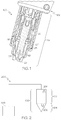
- FIG. 12 is a cross-sectional view of an example thermal processing torch illustrating various signal devices affixed to various torch components.
- FIG. 21 is a cross sectional view of an example magnetic flux field generated from a data tag reading device within a flux communication zone near a magnetic field amplifier.
- Each of the various consumables include a body that defines various features that, as discussed herein, can direct fluids (e.g., gas or liquids) during operation of the torch 100 .
- the torch body 102 which has a generally cylindrical shape, supports the electrode 105 and the nozzle 110 .
- the nozzle 110 is spaced from the electrode 105 and has a central exit orifice mounted within the torch body 102 .
- the swirl ring 120 is mounted to the torch body 102 and has a set of radially offset or canted gas distribution holes 127 that impart a tangential velocity component to the plasma gas flow, causing the plasma gas flow to swirl.
- FIG. 2 shows an exemplary communication network 200 of the present invention.
- the communication network 200 includes one or more signal devices (e.g., a readable data storage device) 202 , each assigned to a consumable of a thermal processing torch, such as the plasma arc torch 100 of FIG. 1 .
- the readable data storage device 202 is located on (e.g., coupled to) the body or located within (e.g., integrated within) the body.
- Exemplary consumables include the electrode 105 , the nozzle 110 , the retaining cap 115 , the swirl ring 120 , and the shield 125 .
- a signal device 202 is an electrically writable device configured to transmit information about a consumable in the form of one or more signals.
- the communication network 200 also includes at least one receiver (e.g., a data reading device arranged in or on the torch) 204 for (i) receiving signals transmitted by the signal devices 202 (e.g., reading the data storage device 202 ), (ii) extracting data conveyed by the signals, and (iii) providing the extracted data to a processor 206 for analysis and further action.
- the data reading device 204 is also a data writing device that is configured to write data to a rewritable storage device positioned within the torch.
- information is encoded to a signal device 202 at the time of manufacture of the corresponding consumable.
- Information can also be encoded to a signal device 202 during the lifetime of the consumable, such as after each consumable use.
- Such information can include the date, time and location of consumable use, any abnormalities detected during use, and/or consumable conditions after use so that a log can be created to predict a failure event or end-of-life event associated with the consumable.
- the information encoded to a signal device 202 can also specify operating parameters (e.g., operation instructions or operating data). For example, for a signal device 202 associated with the shield 125 , data encoded to the signal device 202 can indicate the type of shield gas and/or the appropriate gas flow rate for the shield 125 .
- encoded data of a signal device 202 provides information about other related torch components. For example, encoded data can identify other torch components that are compatible with the assigned consumable, assisting with installation of the entire consumable set in a torch to achieve certain performance metrics.
- the operating parameters include one or more of various types of information or data that can be utilized by the thermal processing system 100 during use.
- the firmware update residing on the readable data storage device can include an identifying code (e.g., a date code, a revision identifying (e.g., a revision number), or any of various other suitable identifying codes) which the data reading device can read and consider.
- the information comprises full control software that can be sent to the data reading device and installed by the controller.
- consumable components can be “pre-loaded” with information (e.g., operating parameters) that make the consumable preferred for any of various types of cutting performance characteristics.
- information e.g., operating parameters
- a consumer e.g., machine operator
- preferred cutting characteristics include fast cutting, slow cutting, high quality cutting edges, reduced kerf, reduced workpiece splatter, straight line cutting, curved cutting, circle cutting, clockwise or counterclockwise cutting, or various other cutting characteristics.
- the signal device 202 and/or the receiver 204 are encrypted in order to limit (e.g., prevent) a third party from interfering (e.g., fraudulently interfering) or altering data stored on the signal device 202 .
- encryption can help to limit a third party from fraudulently storing incorrect usage data or set up information (e.g., operating parameters) onto a consumable, which could cause a thermal processing system to mistake or misinterpret a used (e.g., used to the end life) consumable as an usable consumable.
- encryption can be used in order to code consumables for use with only one type (e.g., manufacturer or OEM brand) or thermal processing system.
- the signal device 202 is located inside or on the torch 100 .
- the signal device 202 can be attached to a surface of a consumable that is ultimately installed inside of the torch tip 104 .
- the signal device 202 can also be attached to a component inside of the torch 100 other than the assigned consumable.
- the signal device 202 can be affixed to a surface of the retaining cap 115 .
- the signal device 202 is coupled to an external source that is not physically associated with the torch 100 .
- the signal device 202 can be attached to a package used to store the consumable and is remote from the consumable once it is installed in the torch 100 .
- the signal device 202 can wirelessly transmit its stored information to the receiver 204 in the form of one or more signals.
- the receiver 204 is adapted to process these signals to extract pertinent data about the consumable and forward the data to the processor 206 for analysis.
- the receiver 204 is located in or on the plasma arc torch 100 .
- the receiver 204 can be located in the torch body 102 .
- the receiver 204 is at a location external to the torch 100 , such as attached to a power supply module, a gas console, the processor 206 , etc.
- the distance between an RFID tag and a reader can be from less than one inch to 100 feet or more, depending on the power output, the radio frequency used and the type of material through which the RF signals need to travel. In one example, the distance between an RFID tag and an antenna of a corresponding reader can be about 2-4 cm.
- a reader antenna and remaining reader components do not need be in the same packaging.
- the reader antenna can be located on or inside of the torch body 102 while the remaining reader components are external to the torch 100 .
- Using an RFID tag is advantageous because it does not require direct contact (e.g., via wires) or direct line of sight (e.g., via optical signals) with the reader and is well suited for use in harsh environments.
- a signal device 202 is a detector (e.g., a sensor) for detecting at least one physical marker of the consumable for uniquely identifying the consumable by its type or individually.
- the physical marker can be a physical alteration of the consumable, for example.
- identification of a consumable is achieved by altering the geometry of the consumable such that, when it is installed in the torch 100 , it affects the wall of an adjacent coolant passageway 402 , which in turn alters the rate of a coolant flowing therethrough. Specifically, the altered section of the coolant passageway 402 can restrict the rate of the coolant flow.
- a signal device 202 can be used to measure the pressure change as a function of the coolant flow rate.
- the measured coolant pressure change serves as an identification of the consumable.
- an auxiliary vent line 404 that is connected to a valve and a flow meter is attached to the nozzle 110 to identify the nozzle 110 .
- the valve is opened prior to plasma arc ignition and the auxiliary vent line flow rate is measured by a signal device 202 as a function of plasma pressure during a purge cycle. Therefore, the measured flow rate serves as an identification of the nozzle 110 .
- one or more uniquely sized metering holes can be drilled into the outer retain cap to identify the cap once it is installed in the torch 100 .
- a signal device 202 is a barcode that provides optical machine-representation of data about the corresponding consumable.
- a barcode can be read by the receiver 204 in the form of a barcode reader.
- a signal device 202 can convey data about a consumable in the form of any machine readable signals, including radio signals, optical or other light-based signals (e.g., infrared signals or ultraviolet signals), magnetic signals, pneumatic signals, or hydraulic signals.
- Each receiver 204 is configured (e.g., tuned) to read signals from one or more of the signal devices 202 and transmit the extracted data to the processor 206 .
- a single receiver 204 is used to read signals from all signal devices 202 in the communication network 200 .
- the processor 206 thus can simultaneously process data associated with multiple consumables.
- the processor 206 can control and verify one or more of the following system components: (i) settings of the power supply 304 for regulating power to the torch 100 , (ii) settings of the nesting software 312 for processing a workpiece, (iii) settings of the gas console 308 for controlling shield and/or plasma gases supplied to the torch 100 , (iv) settings of the height controller 310 for adjusting the height between the torch 100 and the workpiece, and (v) settings of various motors and drivers 306 .
- the processor 206 interacts with the nesting software 312 to automatically select a cutting program that sets parameters for processing a workpiece, such as the cutting speed, direction, paths, nesting sequences, etc.
- the cutting program can also define the gas types, gas pressure and/or flow settings and height control settings for the torch in view of the collected consumable data.
- an operator needs to manually configure the nesting software 312 to create the cutting program for the torch by supplying information to the software including the type and thickness of the workpiece material being processed, the type of gas being used, and the current rating of the consumable set.
- the processor 206 selects a suitable cutting program from the nesting software 312 by taking into consideration of consumable data from the signal devices 202 and user-input operating parameters, including the characteristics of the workpiece being cut and the desired cut shape. For example, an operator can first send a generic program file to the nesting software 312 .
- the generic program file specifies, for each workpiece thickness, variable cut speeds, gas flows, kerf compensations, torch heights, etc. that change with different consumable parts.
- the processor 206 interacts with the generic program file to configure a cutting program for the torch.
- the processor 206 manipulates the torch height controller 310 , which sets the height of the torch 100 relative to the workpiece.
- the torch height controller 310 can include a control module to control an arc voltage during cutting by adjusting the standoff (i.e., the distance between the torch 100 and the work piece) to maintain a predetermined arc voltage value.
- the torch height controller 310 can also include an external control module to control the standoff.
- the torch height controller 310 can further include a lifter, which is controlled by the control module through a motor or driver 306 , to slide the torch 100 in a vertical direction relative to the workpiece to maintain the desired voltage during cutting.
- the torch height controller 310 can automatically determine the height to position the torch relative to the top of a workpiece. Therefore, the torch height controller 310 does not need to perform a height sense in order to set an appropriate pierce height and cut height before beginning arc voltage control.
- the processor 206 manipulates the motors and drivers 306 to move the torch 100 laterally in relation to the surface of the workpiece. The processor 206 can also manipulate the height controller 310 to move the torch 100 vertically in relation to the surface of the workpiece.
- the processor 206 is configured to prevent the thermal processing system 300 from commencing an operation on the workpiece if it determines that the consumables installed in the torch 100 are mismatched with each other, not compatible with the thermal processing system 300 or inconsistent with other pre-selected operating parameters input by an operator. If such a determination is made, the processor 206 can trigger an audio or visual alert indicating to the operator that one or more of the connected consumables are unsupported and that the consumables should be replaced or operator inputs should be revised. Additionally, the processor 206 can prevent initiation of an operation if an alert is triggered.
- the processor 206 recommends one or more remedial actions to the operator to address alarm situations. For example, the processor 206 can suggest one or more consumables to install in the torch 100 to avoid potential mismatch with other components of thermal processing system 300 . The processor 206 can suggest suitable types of workpiece for processing based on the ratings of the installed consumable set. The processor 206 can recommend a cutting sequence that reconciles the settings of the installed consumables with settings provided by the operator.
- the signal devices 202 can store information about torch components other than consumables.
- the signal devices 202 can store information about the torch body 102 or about one or more leads. Therefore, as one in the art will fully appreciate, the exemplary communication network 200 of FIG. 2 and the configuration of FIG. 3 can be easily adapted to store information about any torch component.
- an operator places a workpiece on the cutting table 520 and mounts the torch 100 into the torch height controller 512 , which is attached to the gantry 522 .
- the driver system 516 and the height controller 512 provide relative motion between the tip of the torch 100 and the workpiece while the torch 100 directs plasma arc along a processing path on the workpiece.
- at least one receiver 204 is attached to a component of the thermal processing system 500 to receive signals emitted by at least one signal device 202 associated with one or more consumables of the torch 100 .
- a receiver 204 can be coupled to the gantry 522 to read signals from the torch 100 after the torch 100 is installed into the system 500 .
- the receiver 204 can also be attached to other system components including, for example, the CNC 502 , the height controller 512 , the driver system 516 or the cutting table 520 .
- the receiver 204 is mounted inside or on the surface of the torch 100 .
- multiple receivers 204 are disbursed throughout the system 500 external to the torch 100 , each receiver 204 being tuned to read data concerning one or more specific consumables of the torch 100 .
- the receiver 204 can transmit the information to the CNC 502 , which uses the information to configure the thermal processing system 500 for processing.
- signal devices 202 associated with two sets of physically identical (or at least substantially identical) consumables are encoded with different consumable information and installed into two different torches.
- a signal device for the nozzle of one torch can be encoded with Serial Number A while another signal device for the nozzle of a second torch can be encoded with Serial Number B, even though the two nozzles are manufactured to identical design specifications.
- the nozzles are installed into the respective torches.
- the two torches are installed into their respective thermal processing systems, and the receiver 204 of each thermal processing system can receive consumable data from the signal device 202 of each torch.
- the signal devices 1202 a - g can be in various forms and configurations that are suitable to communicate with the receivers 1204 a , 1204 b .
- the signal devices are formed of circular, ring-like components containing or enclosing one or more RFID tags that store information relating to the various torch components on which they are installed.
- the ring-like signal devices can be affixed to the respective torch components by any of various connection techniques including threaded connections, adhesives or a welded connection, or a press or friction fit.
- the ring-like signal devices can be integrally formed as a feature of the torch consumable.
- other arrangements and configurations are possible.
- dividing or distributing data onto different consumable components By dividing or distributing data onto different consumable components, less data is typically required to be stored on a single signal device which can result in easier to configure, program, and manage signal devices. Additionally, dividing data onto different consumable components is expected to create a more versatile and customizable thermal processing system as a result of different consumable components being able to be mixed and matched in various different configurations while properly providing adequate operating parameters to the torch system.
- a rewritable data storage device is typically able to add new data after the initial writing of data (e.g., with or without deleting or overwriting other data present on the data storage device).
- the rewritable data storage device is typically able to have new data written while disposed within the torch.
- the operation configuration includes the consumable component being installed within a torch of the thermal processing system ready for use.
- the operation configuration includes the thermal processing system being turned on for operation (e.g., being used).
- the operation configuration can include the torch being in use (e.g., undergoing a processing (e.g., cutting) operation in the field).
- the information could be used to track usage in order to troubleshoot the machine, in order to review and handle warranty issues (e.g., by being able to observe how an operator was previous using the consumable and thermal processing system prior to inquiring about a warranty), or in order to predict the end of life of the consumable.
- the signal device can be a data tag (e.g., an RFID data tag) configured to communicate with a reading device of a material processing head.
- the data tag 1304 can have a central axis 1305 (shown in FIG. 14 ) that is substantially coaxial with the central longitudinal axis 1301 of the body 1302 .
- the data tag can be disposed substantially perpendicular to the central longitudinal axis 1301 of the body.
- the consumable can include a cartridge consumable device that is configured to replace one or more other consumable components.
- a cartridge consumable device is a component that typically includes a housing, a connection mechanism for coupling the cartridge to a plasma arc torch, and components including at least an arc constrictor (e.g. a nozzle) and an arc emitter (e.g. an electrode), and optionally including a swirl ring or swirling feature, a shield, and/or a retaining cap.
- the cartridge enhances consumable alignment and/or spacing because cartridge parts are assembled in a manufacturing setting, thereby achieving tighter tolerances than are possible in the field.
- the cartridge improves heat dissipation and/or conduction capabilities.
- heat is moved substantially away from the torch, but not so far as to heat or melt plastic components.
- the housing can have an outer shape that is non-circular, such as polygonal (e.g., triangular, square, hexagonal) or other non-circular shapes.
- the housing 1306 can be formed of any structurally suitable (and in some cases chemically resistant) materials such as various plastics.
- the conductive coil 1308 is typically formed around the central axis 1305 of the data tag 1304 .
- the conductive coil 1308 can encircle (e.g., symmetrically surround) the central axis 1305 .
- the conductive coil 1308 can include substantially a single turn (e.g., to form a ring) or can include multiple turns and can be formed along a substantially helical path.
- FIG. 17 illustrates an example helical coil having a radius R, a height H, and a number of turns N (e.g., number of revolutions of the coil). As discussed below, the number of turns N of the coil can be adjusted to improve communications, for example, to tune a resonant frequency of the data tag.
- the conductive coil 1308 can be formed of any of various materials.
- the conductive coil 1308 can be formed of a metallic material (e.g., a helical coil).
- the conductive coil 1308 can include a winding of wire (e.g., bare metal wire (e.g., copper wire)).
- the conductive coil can be a printed circuit.
- the printed circuit can include a printed coil of a conductive material (e.g., a conductive ink material).
- FIG. 15 depicts an example path of a coil current 1502 (e.g., a current traveling through a ring-shaped conductive coil (e.g., coil 1308 )).
- the coil 1308 can be disposed substantially symmetrically about the central axis 1301 of the consumable, which can be coaxial with the central axis 1305 of the data tag.
- aligning the magnetic flux 1504 centrally through the consumable body 1302 can help to limit adverse effects on the material processing head operation or on communication of the data tag. For example, in a plasma arc torch in which an operating current travels through the body 1302 , aligning the operating current and the magnetic flux 1502 can reduce the likelihood that the flux would adversely impact the operating current. Additionally or alternatively, such alignment could reduce the likelihood that the operating current could distort or otherwise affect the magnetic flux 1504 , which could affect the tag current and the ability for the tag to function properly.
- data stored on the chip is divided into two or more segments.
- a first segment of the data can be locked and a second segment of the data can be unlocked.
- the first segment and the second segment can both be locked, for example, independently of one another.
- the first segment and second segment can typically be locked and unlocked at different times and for different purposes, such as during system use or during consumable set up.
- the first segment of the data can include consumable identification data (e.g., serial numbers, manufacturer information, a type of a consumable, etc.) and the second segment of the data can include data pertaining to the operation of the consumable (e.g., number of hours used in operation, operating conditions used during operation, estimated hours until failure, desired operating instructions to be used with the consumable, etc.).
- consumable identification data e.g., serial numbers, manufacturer information, a type of a consumable, etc.
- the second segment of the data can include data pertaining to the operation of the consumable (e.g., number of hours used in operation, operating conditions used during operation, estimated hours until failure, desired operating instructions to be used with the consumable, etc.).
- potential data locking configurations can include: i) locking the unique identification number (e.g., serial numbers) at the time when the data tag is manufactured; ii) locking some data at different times and steps (e.g., milestones) while the data tag is being manufactured; iii) locking some data at different times as the data tag is being distributed (e.g., passing through its distribution channel); iv) locking some data at different times during the data tag's usage or service life; and/or v) never locking certain portions of data space.
- unique identification number e.g., serial numbers
- Memory can also be portioned (e.g., partitioned, divided, etc.) and potentially locked by certain business partners involved in the data tag or consumables manufacture and distribution, such as a manufacture, wholesale distributor, retail seller, equipment servicer, or other involved party.
- Examples of potential data portioning configurations can include: i) a portion of the memory can be controlled by the data tag manufacturer including data content and locking; ii) a portion of the memory can be reserved for a channel partner to determine the memory content (e.g., data to be stored) and locking procedures; and/or iii) a portion of the memory can be reserved for an end-user of the tag to determine the memory content (e.g., data to be stored) and locking procedures.
- Memory portioning techniques can be implemented in addition to, or in combination with, one or more of the data locking configurations described above.
- Using consumables having ring-shaped data communication signal devices can help to configure material processing systems (e.g., plasma arc systems) to have better communication between signal devices associated with consumables and a reading device of the material processing system.
- material processing systems e.g., plasma arc systems
- ring-shaped data tags e.g., ring-shaped conductive coils
- methods for reducing communication interference of an RFID communication system in a plasma arc or welding torch having a consumable component disposed therein can include providing a ring-shaped RFID tag (e.g., the data tag 1304 ) coaxially disposed relative to the consumable component (e.g., the consumable body 1302 ).
- the data tag can define an open central portion (e.g., central opening 1312 ) and has a conductive coil (e.g., the coil 1308 ) disposed substantially around the open central portion.
- the conductive coil can include a magnetic material (e.g., wire) wound in a circular shape to be disposed around the open central portion.
- the consumable component can be positioned in a torch such that the central axis of the consumable component is disposed along a substantially similar or common axis (e.g., be coaxial with) the open central portion of the RFID tag.
- the data tag can be coupled around the consumable body or at an end of the body so that the conductive coil of the data tag is substantially centered around the central axis of the body.
- a current can be passed along a portion of the central axis of the torch (e.g., along the portion of the consumable) that extends through the ring-shaped RFID tag. That is, a torch current can be passed through a torch (e.g., along a consumable) to generate a cutting medium, such as a plasma cutting current. In some cases, a cutting current can be passed through a central region of the consumable.
- material processing heads can include multiple data tags, which can each be associated with one or more consumable components disposed in a material processing head. Using multiple data tags can help the material processing head identify individual components for any of the various reasons or uses discussed herein. As discussed below, multiple data tags can be constructed and arranged within a material processing head in a manner that helps to facilitate better communication between multiple data tags and a data tag reader.
- the second data tag 1810 which is separated from the reading device 1806 by a second spacing 1811 is farther from the reading device 1806 than the first data tag 1808 , which is separated from the reading device by a first spacing 1809 .
- a majority e.g., a significant majority
- the energy given off by the reading device would be absorbed or captured by the closer, first data tag 1808 , resulting in a large induced current that is predominantly discarded by the first data tag 1808 and resulting in a large counter magnetic flux from the predominantly discarded induced current in the first data tag 1808 which lowers the net magnetic flux reaching the second data tag 1810 and finally results in poor communication between the reading device and the second data tag 1810 .
- the closer data tag would have a smaller induced current through it than it would have if it had not been detuned.
- the smaller induced current creates a smaller counter magnetic flux which results in a greater signal strength between the second data tag and the reading device than would exist without detuning the first data tag.
- a communication signal between the first data tag and the reading device can be about half as strong as a result of detuning than it would be without detuning.
- a received signal strength indicator (RSSI) (on a scale that can range between 0-7 for some implementations, where 0 is the lowest strength and 7 is the highest strength) between the first data tag (e.g., the closer data tag) and the reading device can be de-tuned to be mid-range, such as between about 2 and about 4 (e.g., about 3), and a signal strength between the second data tag and the reading device can be between about 6 and about 7.
- Data tag locations and distances from the reading device coil are typically fixed inside the torch (e.g., when the consumable on which the data tag is attached is installed in the torch) and can be taken advantage of to de-tune the closer data tag (e.g., to reduce the closer data tag coupling with the reading device).
- the data tag's conductive coil will resonate with the capacitor inside the data tag's integrated circuitry. The resonance will allow a higher current to flow inside the coil than without resonance. The amount of the increase in current due to resonance is defined by the Quality Factor (Q) of the resonant circuit.
- Q Quality Factor
- high current flow through a data tag's conductive coil can interfere with the communications of other data tags.
- a reduction in the resonant tag current is expected to reduce the interference.
- the data tag's desired resonant current can be achieved by changing the resonant frequency of the data tag (e.g., slightly), which can have the effect of changing the operating Q of the circuit.
- a resonant frequency of the antenna coil of the reading device can be about 13.5 MHz to about 13.6 MHz
- a resonant frequency of the first data tag can be about 17 MHz to about 20 MHz
- a resonant frequency of the second data tag can be about 13 MHz to about 14 MHz.
- the tag resonant frequencies can deviated from the reading device's broadcast frequency by being either greater than or less than the broadcast frequency, e.g. the first data tag's resonant frequency can alternatively be about 7 MHz to about 10 MHz.
- the first spacing 1809 can be about 1 mm to about 3 mm and the second spacing 1811 can be about 4 mm to about 6 mm.
- the inductance of the conductive coil (e.g., and therefore the resonant frequencies) can be determined by the diameter of the conductive coil material.
- An equation for a simple solenoid is shown below:
- resonant frequencies can be determined by selecting an integrated circuit (IC) capacitor of the data tags to have different capacitance.
- the IC capacitor can have a lower value as seen in Equation 1.
- the first data tag can include a capacitor with a capacitance that is about 20 pico-Faraday (pF) to about 25 pF and the second data tag can include a capacitor with a capacitance that is about 85 pF to about 105 pF.
- a reading device 1904 positioned near (e.g., adjacent) an area of magnetic field inhibiting material (e.g., a metal material) 1905 can generate and broadcast a skewed (e.g., off center or otherwise distorted) flux field 1903 due to the presence of the metal material. That is, the volume of metal material can serve to effectively “push” the flux field.
- the skewed flux field 1903 has been depicted, for simplicity purposed in explanation, as a pushed, off-center field. As depicted, the skewed flux path can fail to align with one or more of data tags 1902 positioned around the reading device 1904 . As a result, communication between data tags 1902 and the reading device 1904 can be inhibited.
- the data tags and be selectively positioned in regions of a material processing head that are conducive to providing a pathway for magnetic flux to travel to generate a magnetic field in which an antenna coil can be excited and energized (e.g., a flux communication zone).
- the flux communication zone can be toroidal in shape.
- the flux communication zone can have (e.g., or define) an open space in all directions around the broadcasting antenna. If the flux communication zone below the antenna (e.g., towards the torch tip) is blocked by a magnetic field inhibiting material (e.g., metal), it is expected to interfere with the flux communication zone on all sides of the antenna (e.g., effectively distorting the flux path as described herein).
- a magnetic field inhibiting material e.g., metal
- FIGS. 6A and 6B are flow diagrams illustrating exemplary operations of the communication network 200 of FIG. 2 .
- FIG. 6A illustrates an exemplary process for assembling thermal processing torches to include one or more consumables and signal devices (e.g., signal devices 202 , 1202 , 1304 ).
- signal devices e.g., signal devices 202 , 1202 , 1304 .
- two consumables are provided, with both consumables manufactured based on the same, or substantially the same, physical specifications.
- the two consumables have identical, or substantially identical, physical characteristics.
- a signal device 202 such as an RFID tag, can be coupled to each of the two consumables.
- Each signal device 202 can be located on or within the body of the corresponding consumable.
- another receiver 204 can read data B from the signal device 202 of the consumable of the second torch.
- the receivers 204 of the thermal processing systems forward the data to the respective CNC's of the thermal processing systems, which set and/or adjust certain parameters of the corresponding thermal processing systems based on the received data to operate the corresponding torches.
- the difference in the encoded data for the two consumables translates to different values for setting the operating parameters of the thermal processing systems, even though the consumables are physically identical to each other.
- the thermal processing systems assign the same values to the operating parameters despite the dissimilarity in the encoded data.
- the plasma arc torch system can include various gas flow detection devices, such as valves, pressure detectors, pressure regulators, gas flow meters, and other devices, which can all be fluidly connected to one another by gas tubing (e.g., semi-rigid tubing or flexible hose).
- gas tubing e.g., semi-rigid tubing or flexible hose.
- the gas supply 702 is typically fluidly connected to a torch system control unit (e.g., a power supply), which can house the supply off-valve 704 , the supply pressure sensor 706 , and the supply gas flow detector 708 (or the combined pressure compensated flow meter).
- a torch system control unit e.g., a power supply
- the supply off-valve 704 can house the supply off-valve 704 , the supply pressure sensor 706 , and the supply gas flow detector 708 (or the combined pressure compensated flow meter).
- the various gas delivery components can be arranged in any number of various different configurations relative to one another as part of the torch system.
- the gas supply 702 is fluidly connected (e.g., via rigid gas lines) to a torch system control unit.
- the supply off-valve 704 , supply pressure sensor 706 , and supply gas flow detector 708 can all be housed within the torch system control unit.
- the supply gas pressure regulator 710 and the off-valve pressure sensor 712 can be located separately from the control unit, for example, disposed on or within a torch gas supply lead line connected to the control unit for providing gas and electricity to a torch.
- the off-valve pressure sensor 712 can be disposed closer to the torch.
- the second pressure determining device can include a pressure sensor (e.g., the vent pressure sensor 714 ) fluidly connected to the torch vent, which can measure the pressure within the plasma plenum, for example, when the vent valve is closed.
- the second pressure determining device includes a vent valve (e.g., the vent off-valve 716 ) that is configured to expose the location downstream from the flow-restriction element (e.g., the torch vent passage) to the atmosphere to set the pressure to atmospheric pressure. That is, in some cases, the second pressure is not explicitly measured by one of the components of the gas delivery system, but is rather set to atmospheric pressure (e.g., 0 psig). As discussed below, such a configuration can permit identification of a consumable using only one pressure sensor when the region downstream of the flow restriction element can be exposed to atmospheric pressure, for example, by opening the vent valve 716 .
- a torch 800 includes a plasma chamber 802 located at an end of a consumable (e.g., nozzle) 803 having one or more flow-restriction elements (e.g., a nozzle exit orifice 805 or a nozzle vent hole 807 ).
- a consumable e.g., nozzle
- flow-restriction elements e.g., a nozzle exit orifice 805 or a nozzle vent hole 807 .
- the plasma chamber 802 can be fluidly connected to a pressure sensor (e.g., the torch plasma plenum pressure sensor 714 ) so that gas pressure within the plasma chamber 802 and/or the plasma plenum 806 can be monitored and measured.
- the plasma chamber 802 is fluidly connected to the pressure sensor via the plasma plenum 806 fluidly connected to a vent line 809 .
- gas e.g., plasma cutting gas
- gas can be delivered from the gas delivery system 700 to the gas supply region 804 , and then be directed to the plasma plenum 806 (towards the vent hole 807 and vent system) and/or be directed through orifice 805 expelled out of the torch.
- the consumable installed within the torch can be identified by directing and monitoring gas flow through these flow-restriction elements (e.g., the vent hole 807 and/or the orifice 805 ).
- the pressure and gas flow rate of the gas flow directed through the consumable can be monitored and measured.
- the measured gas flow rates and pressures can be compared to known (or expected) values for different torch consumables to indicate the type of consumable installed in the torch. For example, measured values can be compared to a lookup table of previously measured values for various particular consumables.
- the pressure of gas flow upstream of the torch that is needed to achieve the predetermined pressure in the plasma plenum e.g., as measured by the off-valve pressure sensor 712
- the measured gas pressure can be compared to expected pressure values for different consumables.
- vent off-valve when the vent off-valve is opened, some gas will flow from the plasma plenum, through the nozzle vent hole, and out of the vent (i.e., the gas stream G 2 ). While the vent is then opened to atmospheric pressure, it is expected that the plasma plenum pressure will not significantly drop (e.g., will not significantly drop below the predetermined pressure) so that there will be a certain pressure upstream of the vent hole (e.g., in the plasma plenum, such as the predetermined pressure), a different (e.g., atmospheric) pressure downstream of the vent hole, and a gas flow therethrough. In some cases, the gas flow through the vent hole can be measured by vent gas flow detector 718 or by supply gas flow detector 708 .
- the pressure (e.g., the first pressure) of the gas being delivered to the torch head can be measured once the predetermined plasma plenum pressure is established.
- the off-valve pressure sensor 712 is used to determine the pressure of gas directed to the flow-restriction element once the predetermined plasma plenum pressure is established.
- the vent off-valve 716 can be opened to vent the region downstream of the flow restriction, such as downstream of a vent hole of a nozzle to atmospheric pressure, and the first pressure can be determined (e.g., measured) upstream using a sensor (e.g., an off-valve pressure sensor 712 ).
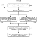
- a vent valve (e.g., the vent off-valve 716 ) coupled to a vent line connected to the plasma chamber can be manipulated to control an outlet flow of the gas from the plasma chamber ( 2308 ). That is, in some embodiments, a previously open vent valve can be manipulated (e.g., closed) to control the outlet flow of the gas from the plasma chamber to limit or prevent the outlet flow of the gas from the plasma chamber via the vent system prior to the criterion being reached. For example, the vent valve can be closed to limit the outlet flow of the gas from the plasma chamber (e.g., substantially eliminating the gas stream G 2 ) so that the plasma plenum pressure can build to the threshold plasma plenum pressure value. Alternatively or additionally, in some embodiments, the vent valve can be opened to vent the vent region downstream of the flow restriction to establish the downstream pressure to be atmospheric pressure.
- a first value of an operating parameter of the torch associated with one of the inlet flow or the outlet flow of the gas can be determined ( 2310 ).
- the operating parameter can include any of various gas flow properties, such as a pressure or flow rate into or out of the consumable.
- the consumable can be identified ( 2312 ). For example, a lookup table that correlates one or more consumables with respective values of one or more operating parameters can be used to identify the consumable based on the first value of the operating parameter.
- the lookup table 2500 as discussed above can be used to identify a consumable installed in the torch.
- a second value of the operating parameter can be measured. That is, when the vent valve is opened and both the gas streams G 1 and G 2 are being expelled from the torch, the various operating parameters (e.g., the supply pressure of the inlet flow, the flow rate of the inlet flow, the off-valve pressure of the inlet flow, or the flow rate of an outlet flow (e.g., G 1 and/or G 2 )) are expected to change as a result of the additional gas flows. Therefore, the second value of the operating parameter and/or the difference or other change between the first and second values can be used to identify the consumable disposed within the torch, for example, using a lookup table.
- the various operating parameters e.g., the supply pressure of the inlet flow, the flow rate of the inlet flow, the off-valve pressure of the inlet flow, or the flow rate of an outlet flow (e.g., G 1 and/or G 2 )
- the second value of the operating parameter and/or the difference or other change between the first and second values can be
- the consumable can be a nozzle having at least one metering hole of a unique dimension for a given nozzle design. That is, different nozzle designs (e.g., nozzles designed for different material types or current values) can include differently sized metering holes, which can be determined using these methods. For example, a particular product line of nozzle, for example an entire line of gouging nozzles, piercing nozzles, or fine cut nozzles can all include the same configuration (e.g., the same size) metering holes.
- an inlet flow of a gas can be directed through a gas supply valve (e.g., the supply off-valve 704 ) and a gas supply line to the plasma chamber of the torch ( 2402 ).
- the gas supply line can include a regulator (e.g., the regulator 710 ) and a plasma off-valve (e.g., the off-valve 704 ) coupled thereto to deliver gas to the torch.
- a flow characteristic can be determined ( 2408 ). For example, in some embodiments, at least one of: (i) a first value of a pressure of the inlet flow (e.g., as measured by the pressure sensor 706 ) ( 2410 ); (ii) a first value of a flow rate of the inlet flow (e.g., as measured by flow detector 708 ) ( 2412 ); (iii) a first value of an off-valve pressure of the inlet flow (e.g., as measured by the off-valve pressure sensor 712 ) ( 2414 ); or (iv) a first value of a flow rate of the outlet flow (e.g., as measured by the vent flow detector 718 ) ( 2416 ) can be determined.
- the vent valve can be adjusted (e.g., manipulated) to permit the outlet flow of the gas from the plasma chamber ( 2418 ). For example, in some embodiments, after the threshold value has been reached and the flow characteristic has been measured, the vent valve can be opened (e.g., partially or fully opened) to permit an outlet flow of gas from the plasma chamber (e.g., through the flow restriction element and downstream of the flow restriction element out of the vent passage). That is, opening the vent valve can cause the torch to begin expelling the gas stream G 2 from the torch. In some cases, adjusting (e.g., manipulating) the vent valve to permit the outlet flow of the gas from the plasma chamber is performed prior to ignition of the torch.
- the opening of the vent valve is expected to alter the flow characteristics of the torch system based on some of the gas entering the torch being expelled as the gas stream G 2 . Therefore, with the outlet flow of gas from the plasma chamber, at least one of various flow characteristics can be determined (e.g., re-measured) ( 2420 ). For example, at least one of: (i) a second value of the pressure of the inlet flow ( 2422 ), (ii) a second value of the flow rate of the inlet flow ( 2424 ), (iii) a second value of the off-value pressure of the inlet flow ( 2426 ), or (iv) a second value of the flow rate of the outlet flow ( 2428 ) can be determined.
- the consumable can be identified ( 2430 ).
- the measured flow characteristics can be referenced to a lookup table (e.g., the lookup table 2500 , as shown in FIG. 25 ).
- While many of the systems and methods herein with respect to FIGS. 7, 8 and 22-25 have generally been described and illustrated as being used and implemented primarily in association with plasma arc torches, they can also be implemented with other material processing systems, such as water-jet systems.
- fluids such as gases or liquids (e.g., water) can be directed to one or more components of a water-jet cutting system, such as a water-jet orifice, a mixing tube used to mix abrasive particles with fluid, and/or one or more high pressure cylinders or pump components to generate the high velocity water flow used to cut material.
Landscapes
- Engineering & Computer Science (AREA)
- Physics & Mathematics (AREA)
- Plasma & Fusion (AREA)
- Mechanical Engineering (AREA)
- Optics & Photonics (AREA)
- Toxicology (AREA)
- Health & Medical Sciences (AREA)
- General Physics & Mathematics (AREA)
- Spectroscopy & Molecular Physics (AREA)
- Artificial Intelligence (AREA)
- Computer Networks & Wireless Communication (AREA)
- Electromagnetism (AREA)
- General Health & Medical Sciences (AREA)
- Computer Vision & Pattern Recognition (AREA)
- Theoretical Computer Science (AREA)
- Forests & Forestry (AREA)
- Life Sciences & Earth Sciences (AREA)
- Automation & Control Theory (AREA)
- Manufacturing & Machinery (AREA)
- Human Computer Interaction (AREA)
- Plasma Technology (AREA)
Abstract
Description
where μ is the permeability of the region containing the magnetic flux, N is the number of turns of the coil, d is the diameter of the coil, and l is the length of the coil. From the equation it can be seen that increasing the diameter of the coil will increase the inductance and decreasing the diameter will decrease the inductance. From equation 1 above, it can be seen that increasing the inductance will decrease the resonant frequency and decreasing the inductance will increase the resonant frequency.
Claims (23)
Priority Applications (3)
| Application Number | Priority Date | Filing Date | Title |
|---|---|---|---|
| US16/892,736 US11087100B2 (en) | 2012-04-04 | 2020-06-04 | Configuring signal devices in thermal processing systems |
| US17/382,992 US11783138B2 (en) | 2012-04-04 | 2021-07-22 | Configuring signal devices in thermal processing systems |
| US18/462,283 US12217118B2 (en) | 2012-04-04 | 2023-09-06 | Configuring signal devices in thermal processing systems |
Applications Claiming Priority (11)
| Application Number | Priority Date | Filing Date | Title |
|---|---|---|---|
| US13/439,259 US10455682B2 (en) | 2012-04-04 | 2012-04-04 | Optimization and control of material processing using a thermal processing torch |
| US13/560,059 US20130263420A1 (en) | 2012-04-04 | 2012-07-27 | Optimization and Control of Material Processing Using a Thermal Processing Torch |
| US13/838,919 US10486260B2 (en) | 2012-04-04 | 2013-03-15 | Systems, methods, and devices for transmitting information to thermal processing systems |
| US14/075,692 US20140061170A1 (en) | 2012-04-04 | 2013-11-08 | Identifying Thermal Processing Torch Components |
| US14/135,714 US9144882B2 (en) | 2012-04-04 | 2013-12-20 | Identifying liquid jet cutting system components |
| US201462028065P | 2014-07-23 | 2014-07-23 | |
| US14/589,270 US9395715B2 (en) | 2012-04-04 | 2015-01-05 | Identifying components in a material processing system |
| US14/807,679 US20150332071A1 (en) | 2012-04-04 | 2015-07-23 | Configuring Signal Devices in Thermal Processing Systems |
| US15/863,402 US10346647B2 (en) | 2012-04-04 | 2018-01-05 | Configuring signal devices in thermal processing systems |
| US16/425,197 US10713448B2 (en) | 2012-04-04 | 2019-05-29 | Configuring signal devices in thermal processing systems |
| US16/892,736 US11087100B2 (en) | 2012-04-04 | 2020-06-04 | Configuring signal devices in thermal processing systems |
Related Parent Applications (1)
| Application Number | Title | Priority Date | Filing Date |
|---|---|---|---|
| US16/425,197 Continuation US10713448B2 (en) | 2012-04-04 | 2019-05-29 | Configuring signal devices in thermal processing systems |
Related Child Applications (1)
| Application Number | Title | Priority Date | Filing Date |
|---|---|---|---|
| US17/382,992 Continuation US11783138B2 (en) | 2012-04-04 | 2021-07-22 | Configuring signal devices in thermal processing systems |
Publications (2)
| Publication Number | Publication Date |
|---|---|
| US20200293727A1 US20200293727A1 (en) | 2020-09-17 |
| US11087100B2 true US11087100B2 (en) | 2021-08-10 |
Family
ID=54538758
Family Applications (4)
| Application Number | Title | Priority Date | Filing Date |
|---|---|---|---|
| US14/807,679 Abandoned US20150332071A1 (en) | 2012-04-04 | 2015-07-23 | Configuring Signal Devices in Thermal Processing Systems |
| US15/863,402 Active US10346647B2 (en) | 2012-04-04 | 2018-01-05 | Configuring signal devices in thermal processing systems |
| US16/425,197 Active US10713448B2 (en) | 2012-04-04 | 2019-05-29 | Configuring signal devices in thermal processing systems |
| US16/892,736 Active US11087100B2 (en) | 2012-04-04 | 2020-06-04 | Configuring signal devices in thermal processing systems |
Family Applications Before (3)
| Application Number | Title | Priority Date | Filing Date |
|---|---|---|---|
| US14/807,679 Abandoned US20150332071A1 (en) | 2012-04-04 | 2015-07-23 | Configuring Signal Devices in Thermal Processing Systems |
| US15/863,402 Active US10346647B2 (en) | 2012-04-04 | 2018-01-05 | Configuring signal devices in thermal processing systems |
| US16/425,197 Active US10713448B2 (en) | 2012-04-04 | 2019-05-29 | Configuring signal devices in thermal processing systems |
Country Status (1)
| Country | Link |
|---|---|
| US (4) | US20150332071A1 (en) |
Cited By (1)
| Publication number | Priority date | Publication date | Assignee | Title |
|---|---|---|---|---|
| US12217118B2 (en) | 2012-04-04 | 2025-02-04 | Hypertherm, Inc. | Configuring signal devices in thermal processing systems |
Families Citing this family (27)
| Publication number | Priority date | Publication date | Assignee | Title |
|---|---|---|---|---|
| US10455682B2 (en) | 2012-04-04 | 2019-10-22 | Hypertherm, Inc. | Optimization and control of material processing using a thermal processing torch |
| US10486260B2 (en) * | 2012-04-04 | 2019-11-26 | Hypertherm, Inc. | Systems, methods, and devices for transmitting information to thermal processing systems |
| US20150332071A1 (en) * | 2012-04-04 | 2015-11-19 | Hypertherm, Inc. | Configuring Signal Devices in Thermal Processing Systems |
| US9981335B2 (en) | 2013-11-13 | 2018-05-29 | Hypertherm, Inc. | Consumable cartridge for a plasma arc cutting system |
| US11684995B2 (en) | 2013-11-13 | 2023-06-27 | Hypertherm, Inc. | Cost effective cartridge for a plasma arc torch |
| US11278983B2 (en) | 2013-11-13 | 2022-03-22 | Hypertherm, Inc. | Consumable cartridge for a plasma arc cutting system |
| US11432393B2 (en) | 2013-11-13 | 2022-08-30 | Hypertherm, Inc. | Cost effective cartridge for a plasma arc torch |
| US10456855B2 (en) | 2013-11-13 | 2019-10-29 | Hypertherm, Inc. | Consumable cartridge for a plasma arc cutting system |
| US10786924B2 (en) | 2014-03-07 | 2020-09-29 | Hypertherm, Inc. | Waterjet cutting head temperature sensor |
| US20150269603A1 (en) | 2014-03-19 | 2015-09-24 | Hypertherm, Inc. | Methods for Developing Customer Loyalty Programs and Related Systems and Devices |
| JP6437227B2 (en) | 2014-07-18 | 2018-12-12 | 株式会社ヨコオ | In-vehicle antenna device |
| CN106715027B (en) * | 2014-08-12 | 2020-04-21 | 海别得公司 | Cost-effective cartridge for plasma arc torch |
| CN104759753B (en) * | 2015-03-30 | 2016-08-31 | 江苏大学 | The co-ordination of multisystem automatization improves the method for induced with laser cavitation reinforcement |
| KR102586885B1 (en) | 2015-08-04 | 2023-10-06 | 하이퍼썸, 인크. | Cartridges for liquid-cooled plasma arc torches |
| FR3047074B1 (en) * | 2016-01-21 | 2018-01-26 | Pfeiffer Vacuum | SPRAY DEVICE AND LEAK DETECTION MODULE |
| CA3030109A1 (en) * | 2016-07-18 | 2018-01-25 | Victor Equipment Company | Plasma device consumable part change detection |
| US10195683B2 (en) * | 2016-11-14 | 2019-02-05 | Matthew Fagan | Metal analyzing plasma CNC cutting machine and associated methods |
| US10300551B2 (en) * | 2016-11-14 | 2019-05-28 | Matthew Fagan | Metal analyzing plasma CNC cutting machine and associated methods |
| US11267069B2 (en) * | 2018-04-06 | 2022-03-08 | The Esab Group Inc. | Recognition of components for welding and cutting torches |
| US10625359B2 (en) | 2018-04-06 | 2020-04-21 | The Esab Group Inc. | Automatic identification of components for welding and cutting torches |
| DE102018003123A1 (en) * | 2018-04-17 | 2019-10-17 | Bräuer Systemtechnik GmbH | Arrangement for monitoring tools when machining rotationally symmetrical workpieces |
| IT201800011036A1 (en) * | 2018-12-12 | 2020-06-12 | Bicarjet S R L | SANDBLASTING MACHINE WITH ABRASIVE MATERIAL LOADING CONTROL SYSTEM |
| US11188052B2 (en) * | 2019-03-29 | 2021-11-30 | Illinois Tool Works Inc. | Systems and methods to provide vendor managed inventory with active tracking |
| US11664971B2 (en) | 2019-11-13 | 2023-05-30 | The Esab Group Inc. | Encrypted communication between components of welding and cutting systems |
| DE102021108738A1 (en) * | 2020-04-09 | 2021-10-14 | Robert Bosch Gesellschaft mit beschränkter Haftung | WELDING POINT ANALYSIS |
| EP3928960B1 (en) * | 2020-06-25 | 2023-09-20 | Georg Fischer Omicron S.r.l. | Method and device for welding electrofusion fittings |
| US11839015B2 (en) | 2021-02-04 | 2023-12-05 | The Esab Group Inc. | Consumables for processing torches |
Citations (213)
| Publication number | Priority date | Publication date | Assignee | Title |
|---|---|---|---|---|
| US2985050A (en) | 1958-10-13 | 1961-05-23 | North American Aviation Inc | Liquid cutting of hard materials |
| US3010012A (en) * | 1959-12-24 | 1961-11-21 | Air Reduction | Arc welding |
| US3018360A (en) * | 1960-04-25 | 1962-01-23 | Air Reduction | Arc welding torch |
| US3518401A (en) * | 1967-10-04 | 1970-06-30 | Air Reduction | Electric arc pulsing |
| US3602683A (en) | 1969-02-03 | 1971-08-31 | Sumitomo Heavy Industries | Automatic control mechanism for plasma welder |
| US3996070A (en) | 1974-11-22 | 1976-12-07 | Nasa | Thermocouple installation |
| US4125754A (en) | 1976-01-15 | 1978-11-14 | Rene Wasserman | Installation for surfacing using plasma-arc welding |
| US4497029A (en) * | 1981-04-15 | 1985-01-29 | Mitsubishi Denki Kabushiki Kaisha | Numerical control device |
| US4519835A (en) * | 1981-07-30 | 1985-05-28 | Hydro-Quebec | Transferred-arc plasma reactor for chemical and metallurgical applications |
| JPS6163368A (en) | 1984-09-03 | 1986-04-01 | Takashi Murata | Automatic setting method of welding condition for covered electrode |
| US4588880A (en) * | 1982-09-16 | 1986-05-13 | Robert Bosch Gmbh | Non-contacting code recognition system for code carriers on production line workpieces |
| US4733052A (en) * | 1985-02-15 | 1988-03-22 | Esab Aktiebolag | Contact tip welding electrode |
| US4742470A (en) * | 1985-12-30 | 1988-05-03 | Gte Valeron Corporation | Tool identification system |
| US4929811A (en) * | 1988-12-05 | 1990-05-29 | The Lincoln Electric Company | Plasma arc torch interlock with disabling control arrangement system |
| US5018670A (en) | 1990-01-10 | 1991-05-28 | Possis Corporation | Cutting head for water jet cutting machine |
| US5050106A (en) * | 1987-10-07 | 1991-09-17 | Omron Tateisi Electronics Co. | Article recognizing system |
| US5086655A (en) | 1985-10-15 | 1992-02-11 | Avl Gesellschaft Fuer Verbrennungskraftmaschinen Und Messtechnik Mbh | Orifice measuring device |
| US5099226A (en) * | 1991-01-18 | 1992-03-24 | Interamerican Industrial Company | Intelligent security system |
| EP0508482A2 (en) | 1991-04-12 | 1992-10-14 | The Lincoln Electric Company | Plasma torch with identification circuit |
| JPH05154732A (en) | 1991-11-30 | 1993-06-22 | Nippei Toyama Mechatronics:Kk | Machining device with tool exchanging system |
| US5248867A (en) * | 1990-11-30 | 1993-09-28 | Mitsubishi Denki K.K. | Electric spark machine |
| US5309683A (en) | 1992-01-28 | 1994-05-10 | Sandroid Systems, Inc. | Recovery system |
| US5381487A (en) * | 1989-01-25 | 1995-01-10 | Shamos; Morris H. | Patient identification system |
| US5388965A (en) | 1990-10-10 | 1995-02-14 | Friedrich Wilhelm Schwing Gmbh | Sludge pump with monitoring system |
| US5390964A (en) * | 1992-10-01 | 1995-02-21 | Gray, Jr.; Lawrence C. | Labeled pipe fitting and method |
| US5400389A (en) * | 1992-05-19 | 1995-03-21 | Fujitsu Limited | System for rewriting information in rewritable memory provided in portable remote terminal and portable remote terminal applicable to the system |
| US5440477A (en) | 1991-05-20 | 1995-08-08 | Creative Pathways, Inc. | Modular bottle-mounted gas management system |
| US5500512A (en) | 1994-12-16 | 1996-03-19 | General Electric Company | Welding wire verification control system |
| US5556562A (en) * | 1994-12-12 | 1996-09-17 | J. W. Harris Co., Inc. | Welding assembly |
| US5643058A (en) | 1995-08-11 | 1997-07-01 | Flow International Corporation | Abrasive fluid jet system |
| US5653264A (en) | 1995-10-13 | 1997-08-05 | Atkinson; Louis D. | Fluid orifice device having encoded orifice size indicia |
| US5717187A (en) * | 1994-03-25 | 1998-02-10 | Commonwealth Scientific And Industrial Research Organisation | Plasma torch condition monitoring |
| US5860849A (en) | 1997-03-25 | 1999-01-19 | Huffman Corp | Liquid abrasive jet focusing tube for making non-perpendicular cuts |
| JPH11285831A (en) | 1998-04-07 | 1999-10-19 | Koike Sanso Kogyo Co Ltd | Cutting device |
| US5994663A (en) | 1996-10-08 | 1999-11-30 | Hypertherm, Inc. | Plasma arc torch and method using blow forward contact starting system |
| US6047579A (en) * | 1998-04-17 | 2000-04-11 | The Minster Machine Company | RF tag attached to die assembly for use in press machine |
| US6130407A (en) * | 1998-07-29 | 2000-10-10 | Tregaskiss, Ltd. | Arc welding torch |
| US6133542A (en) * | 1996-07-04 | 2000-10-17 | Castolin S.A. | Process for coating or welding easily oxidized materials and plasma torch for carrying out this process |
| EP1065620A2 (en) | 1999-06-21 | 2001-01-03 | Lincoln Global, Inc. | Coded and electronically tagged welding wire |
| US6201207B1 (en) * | 2000-01-13 | 2001-03-13 | Koike Sanso Kogyo Co., Ltd. | Torch angle setting apparatus |
| US6248975B1 (en) * | 1997-05-16 | 2001-06-19 | Illinois Tool Works Inc. | Welding machine with automatic parameter setting |
| US6259059B1 (en) * | 1999-12-21 | 2001-07-10 | Lincoln Global, Inc. | Arc welder and torch for same |
| EP1117279A1 (en) | 2000-01-17 | 2001-07-18 | L'air Liquide, Societe Anonyme Pour L'etude Et L'exploitation Des Procedes Georges Claude | Plasma torch with head, electrode and nozzle identification means |
| US6326583B1 (en) | 2000-03-31 | 2001-12-04 | Innerlogic, Inc. | Gas control system for a plasma arc torch |
| US6409476B2 (en) | 1999-08-06 | 2002-06-25 | Djax Corporation | Pumpjack dynamometer and method |
| US20020117484A1 (en) | 2001-02-27 | 2002-08-29 | Jones Joseph P. | Contact start plasma arc torch and method of initiating a pilot arc |
| US6479793B1 (en) | 1998-05-13 | 2002-11-12 | Fronius Schweissmaschinen Produktion Gmbh & Co. Kg | Method for controlling a welding apparatus and corresponding control device |
| US20020194064A1 (en) | 2001-06-01 | 2002-12-19 | Parry Travis J. | Methods and apparatus for promoting use of consumable goods in imaging devices |
| JP2003025176A (en) | 2001-07-11 | 2003-01-29 | Incs Inc | Tool management system |
| US20030025598A1 (en) | 2000-01-10 | 2003-02-06 | Filterwerk Mann & Hummel Gmbh | Method and apparatus for monitoring service-intensive replaceable parts in an assembly |
| US20030029934A1 (en) | 2001-07-31 | 2003-02-13 | Flow International Corporation | Multiple segment high pressure fluidjet nozzle and method of making the nozzle |
| JP2003048134A (en) | 2001-08-07 | 2003-02-18 | Incs Inc | Tool managing system |
| EP1288016A1 (en) | 2001-01-11 | 2003-03-05 | Hanex Co. Ltd | Communication device and its installation structure, manufacturing method, and communication method |
| US6539813B1 (en) | 1999-11-15 | 2003-04-01 | Smc Kabushiki Kaisha | Throttle structure and flow meter incorporated with throttle structure |
| US20030148709A1 (en) | 2002-02-05 | 2003-08-07 | The Johns Hopkins University | Porous, lubricated nozzle for abrasive fluid suspension jet |
| US6657162B1 (en) * | 1999-05-31 | 2003-12-02 | Alexander Binzel Schweisstechnik Gmbh & Co. Kg | Burner head of an electric arc welding or cutting burner with contact nozzle supported in positive fit |
| US6659098B1 (en) * | 1999-11-10 | 2003-12-09 | Disco Corporation | Rotary tool including a cutting blade and cutting apparatus comprising the same |
| US20040004113A1 (en) | 1999-06-21 | 2004-01-08 | Lincoln Global, Inc., A Delaware Corporation | Coded welding consumable |
| US6693252B2 (en) | 2002-04-01 | 2004-02-17 | Illinois Tool Works Inc. | Plasma MIG welding with plasma torch and MIG torch |
| US20040031776A1 (en) | 2002-04-29 | 2004-02-19 | Gevelber Michael Alan | Feedback enhanced plasma spray tool |
| US6707304B2 (en) * | 2000-12-12 | 2004-03-16 | Agie Sa | Devices and methods for detecting a processing electrode of a machine tool |
| US6717096B2 (en) | 2001-02-27 | 2004-04-06 | Thermal Dynamics Corporation | Dual mode plasma arc torch |
| US6729468B1 (en) * | 2003-03-28 | 2004-05-04 | Thomas N Dobmeier | Circular saw blade holder |
| US20040106101A1 (en) | 2002-12-02 | 2004-06-03 | Evans Daron G. | System and method for quality control of a shipped neural cell culture on a microelectrode array |
| US6772040B1 (en) | 2000-04-10 | 2004-08-03 | Hypertherm, Inc. | Centralized control architecture for a plasma arc system |
| US6781085B2 (en) | 2002-10-09 | 2004-08-24 | Illinois Tool Works Inc. | Method and apparatus of coordinating operating modes of a plasma cutter and a power supply |
| US20040173583A1 (en) | 2003-02-06 | 2004-09-09 | Komatsu Industries Corporation | Plasma processing apparatus |
| US20040193307A1 (en) | 2003-03-26 | 2004-09-30 | Mori Seiki Co., Ltd. | Maintenance system for machine tool |
| US20050045599A1 (en) | 2003-09-03 | 2005-03-03 | Matus Tim A. | Method and apparatus of coordinating operational feedback in a plasma cutter |
| EP1516688A1 (en) | 2003-09-18 | 2005-03-23 | Illinois Tool Works Inc. | Welding-type system with controller configured for automatic determination of the type of consumables |
| EP1522371A1 (en) | 2003-10-09 | 2005-04-13 | Illinois Tool Works Inc. | Method and apparatus for localized control of a plasma cutter |
| US20050109738A1 (en) | 2003-11-21 | 2005-05-26 | Hewett Roger W. | Color coding of plasma arc torch parts and part sets |
| US20050145688A1 (en) * | 2003-12-29 | 2005-07-07 | Milan Milenkovic | Asset management methods and apparatus |
| US6960737B2 (en) | 2003-08-29 | 2005-11-01 | Thermal Dynamics Corporation | Gas flow pre-charge for a plasma arc torch |
| US20050266777A1 (en) | 2004-05-31 | 2005-12-01 | K.C. Tech Co., Ltd. | Nozzle for spraying sublimable solid particles entrained in gas for cleaning surface and method of cleaning surface using the same |
| US6980704B2 (en) | 1999-05-25 | 2005-12-27 | Silverbrook Research Pty Ltd | Sensing device for sensing coded marks |
| US20060006154A1 (en) * | 2004-05-24 | 2006-01-12 | Tetsuo Koike | Plasma torch life duration detecting device |
| US20060020415A1 (en) | 2004-07-23 | 2006-01-26 | Hardwicke Canan U | Sensor and method for making same |
| US6995545B2 (en) | 2003-08-18 | 2006-02-07 | Mks Instruments, Inc. | Control system for a sputtering system |
| US20060070986A1 (en) | 2004-09-28 | 2006-04-06 | Ihde Jeffery R | System and method of precise wire feed control in a welder |
| US7030337B2 (en) | 2003-12-19 | 2006-04-18 | Honeywell International, Inc. | Hand-held laser welding wand having removable filler media delivery extension tips |
| US20060163228A1 (en) * | 2005-01-25 | 2006-07-27 | Lincoln Global, Inc. | Methods and apparatus for tactile communication in an arc processing system |
| US20060163230A1 (en) | 2005-01-26 | 2006-07-27 | Kaufman Charles L | System and method for coordinating wire feeder motor operation |
| US20060201923A1 (en) | 2005-03-11 | 2006-09-14 | Hutchison Richard M | Method and system of determining wire feed speed |
| US20060215389A1 (en) | 2005-03-24 | 2006-09-28 | Fosbinder Daniel C | Control panel for a welding-type apparatus |
| US7115833B2 (en) | 2004-11-03 | 2006-10-03 | The Esab Group, Inc. | Metering system and method for supplying gas to a torch |
| CA2439213C (en) | 1999-06-21 | 2006-10-10 | Lincoln Global, Inc. | Coded and electronically tagged welding wire |
| US20060289406A1 (en) * | 2003-09-17 | 2006-12-28 | Pekka Helenius | Cooled plasma torch and method for cooling the torch |
| US20070012099A1 (en) | 2005-07-04 | 2007-01-18 | Alcatel | Vacuum line and a method of monitoring such a line |
| CN1919516A (en) | 2005-08-25 | 2007-02-28 | 林肯环球公司 | Torch for electric arc welding system |
| US20070080153A1 (en) | 2005-10-07 | 2007-04-12 | Bruce Albrecht | Wireless tracking and inventory monitoring for welding-type devices |
| US20070080152A1 (en) | 2005-10-07 | 2007-04-12 | Bruce Albrecht | Wireless communication system for welding-type devices |
| US20070193988A1 (en) | 2004-04-08 | 2007-08-23 | 3D Industrie (Sas) | Laser Cutting Machine For Trimming, Adding, Punching Or Similar Comprising A Support For The Removable Laser Head Of A Machine Tool Bed |
| WO2007109636A2 (en) | 2006-03-20 | 2007-09-27 | Monto Kumagai | Rfid-tagged consumer items having personalized event information |
| US7307533B2 (en) * | 2005-01-31 | 2007-12-11 | Fujitsu Limited | Information reading apparatus, information reading system, and RFID tag |
| US20070294608A1 (en) | 2006-05-18 | 2007-12-20 | Huettinger Elektronik Gmbh + Co. Kg | Plasma process power delivery system and method with event-controlled data storage |
| US20080001752A1 (en) * | 2005-04-21 | 2008-01-03 | Skyetek, Inc. | System and method for securing rfid tags |
| US20080011821A1 (en) | 2006-07-10 | 2008-01-17 | Daniel Measurement And Control, Inc. | Method and System of Determining Orifice Plate Parameters |
| US20080023451A1 (en) * | 2006-07-27 | 2008-01-31 | Salsich Anthony V | Method and apparatus for automatically controlling gas pressure for a plasma cutter |
| US20080061049A1 (en) * | 2006-09-07 | 2008-03-13 | Bruce Albrecht | Wireless system control and inventory monitoring for welding-type devices |
| US20080066596A1 (en) * | 2004-05-20 | 2008-03-20 | Komatsu Insustries Corporation | Cutting Machine and Method of Moving Cutting Head |
| US20080083711A1 (en) * | 2006-09-13 | 2008-04-10 | Hypertherm, Inc. | High Visibility Plasma Arc Torch |
| US20080093476A1 (en) | 2005-06-27 | 2008-04-24 | Johnson Kaj A | Modular Sprayer |
| US7375302B2 (en) * | 2004-11-16 | 2008-05-20 | Hypertherm, Inc. | Plasma arc torch having an electrode with internal passages |
| US20080118253A1 (en) | 2006-11-16 | 2008-05-22 | Brother Kogyo Kabushiki Kaisha | Image-forming apparatus |
| US20080149686A1 (en) | 2006-12-20 | 2008-06-26 | Lincoln Global, Inc. | Welding Job Sequencer |
| US20080149608A1 (en) * | 2006-12-22 | 2008-06-26 | Bruce Albrecht | System and method for identifying welding consumable wear |
| US20080156783A1 (en) | 2006-12-29 | 2008-07-03 | Vanden Heuvel Michael L | Portable multi-wire feeder |
| US20080217305A1 (en) | 2007-02-16 | 2008-09-11 | Hypertherm, Inc. | Gas-Cooled Plasma Arc Cutting Torch |
| US20080223952A1 (en) | 2007-03-16 | 2008-09-18 | Sulzer Metco Ag | Device and method for the management of data |
| US20080257874A1 (en) * | 2007-04-19 | 2008-10-23 | Illinois Tool Works Inc. | Synchronized multiple drive wire feed welding system and method |
| WO2008144785A1 (en) | 2007-05-25 | 2008-12-04 | Fronius International Gmbh | Welding system and method for transmitting information and for influencing parameters of a welding system |
| WO2008150136A1 (en) | 2007-06-08 | 2008-12-11 | Plasmart Inc. | Arc detecting apparatus and arc monitoring method using the same |
| US20080308641A1 (en) | 2007-04-10 | 2008-12-18 | Advanced Microelectronic And Automation Technology Ltd. | Smart card with switchable matching antenna |
| US20090008370A1 (en) | 2006-07-27 | 2009-01-08 | Salsich Anthony V | Automatic consumable and torch length detection via pressure decay |
| US20090057286A1 (en) * | 2007-03-19 | 2009-03-05 | Hideki Ihara | Welding device |
| US20090065489A1 (en) | 2005-09-09 | 2009-03-12 | John Duffy | Arc welding |
| US20090078196A1 (en) | 2005-03-14 | 2009-03-26 | Tokyo Electron Limited | Treatment device, treatment device consumable parts management method, treatment system, and treatment system consumable parts management method |
| US20090107960A1 (en) | 2007-10-30 | 2009-04-30 | Gm Global Technology Operations, Inc. | Welding Stability System and Method |
| RU2354460C2 (en) | 2007-04-02 | 2009-05-10 | Обшество с ограниченной ответственностью "ПЛАЗМА" (ООО "ПЛАЗМА") | Portable plasma generator for coating evaporation and overlaying welding |
| WO2009076496A2 (en) | 2007-12-11 | 2009-06-18 | Kennametal Inc. | Cutting tool with integrated circuit chip |
| US20090152255A1 (en) * | 2007-12-18 | 2009-06-18 | Illinois Tool Works Inc. | Retaining head and contact tip for controlling wire contour and contacting point for gmaw torches |
| US20090159575A1 (en) | 2007-12-19 | 2009-06-25 | Illinois Tool Works Inc. | Plasma Cutter Having Microprocessor Control |
| US20090159577A1 (en) | 2007-12-19 | 2009-06-25 | Illinois Tool Works Inc. | Multi-Stage Compressor in a Plasma Cutter |
| US20090163130A1 (en) | 2007-12-21 | 2009-06-25 | Jurijs Zambergs | Ventilation system ofr wide-bodied aircraft |
| US20090159571A1 (en) | 2007-12-19 | 2009-06-25 | Illinois Tool Works, Inc. | Plasma Cutter Having High Power Density |
| US20090159572A1 (en) | 2007-12-19 | 2009-06-25 | Illinois Tool Works Inc. | Plasma Cutter Having Thermal Model for Component Protection |
| US20090184098A1 (en) | 2006-12-05 | 2009-07-23 | Lincoln Global, Inc. | System for measuring energy using digitally controlled welding power sources |
| US20090212027A1 (en) | 2008-02-21 | 2009-08-27 | Hypertherm, Inc. | Binary Signal Detection |
| US20090222804A1 (en) * | 2008-02-29 | 2009-09-03 | Illinois Tool Works, Inc. | Embedded firmware updating system and method |
| US20090219136A1 (en) | 2006-08-03 | 2009-09-03 | Olivier Brunet | Secure Document, In Particular Electronic Passport With Enhanced Security |
| US20090230097A1 (en) * | 2008-03-12 | 2009-09-17 | Hypertherm, Inc. | Liquid cooled shield for improved piercing performance |
| US20090240368A1 (en) | 2008-03-24 | 2009-09-24 | Hypertherm, Inc. | Method and Apparatus for Operating an Automated High Temperature Thermal Cutting System |
| JP2009252085A (en) | 2008-04-09 | 2009-10-29 | Nec Fielding Ltd | Maintenance operation support system and its method |
| WO2009142941A2 (en) | 2008-05-21 | 2009-11-26 | Flow International Corporation | Mixing tube for a waterjet system |
| US20090294415A1 (en) | 2008-05-29 | 2009-12-03 | Salsich Anthony V | System and method for start flow approach control for a proportional valve in a plasma cutter |
| US7645960B2 (en) * | 2004-06-18 | 2010-01-12 | Lincoln Global, Inc. | Coded welding consumable |
| US7651269B2 (en) | 2007-07-19 | 2010-01-26 | Lam Research Corporation | Temperature probes having a thermally isolated tip |
| US20100046210A1 (en) | 2008-08-19 | 2010-02-25 | Plextronics, Inc. | Organic light emitting diode products |
| US7671294B2 (en) * | 2006-11-28 | 2010-03-02 | Vladimir Belashchenko | Plasma apparatus and system |
| US7680625B2 (en) * | 2005-11-14 | 2010-03-16 | Macsema, Inc. | Systems and methods for monitoring system performance |
| US20100084381A1 (en) | 2007-01-11 | 2010-04-08 | Sbi Produktion Techn. Alagen Gmbh | Process for the plasma spot welding of surface-treated workpieces and plasma torch |
| US7728401B2 (en) | 2004-09-06 | 2010-06-01 | Nec Corporation | Thin-film semiconductor device, circuitry thereof, and apparatus using them |
| US20100155377A1 (en) | 2008-12-22 | 2010-06-24 | Hypertherm, Inc. | Method And Apparatus For Cutting High Quality Internal Features And Contours |
| US7755484B2 (en) | 2004-02-12 | 2010-07-13 | Avery Dennison Corporation | RFID tag and method of manufacturing the same |
| WO2010142858A1 (en) | 2009-06-12 | 2010-12-16 | Kemppi Oy | Welding optimisation |
| US20100324868A1 (en) | 2009-06-22 | 2010-12-23 | Russell Mark C | Core Sample Preparation, Analysis, And Virtual Presentation |
| US20110000893A1 (en) | 2009-07-06 | 2011-01-06 | Lincoln Global, Inc. | Synergistic welding and electrode selection and identification method |
| US20110029385A1 (en) | 2009-07-28 | 2011-02-03 | Oohdoo, Inc. | System and method for providing advertising content via mobile device docking station |
| US20110114616A1 (en) | 2009-11-17 | 2011-05-19 | Illinois Tool Works Inc. | Welding system with lockout mechanism |
| US20110163857A1 (en) | 2003-04-09 | 2011-07-07 | Visible Assets, Inc. | Energy Harvesting for Low Frequency Inductive Tagging |
| US20110220630A1 (en) * | 2010-03-10 | 2011-09-15 | Illinois Tool Works Inc. | Welding wire feeder with multimotor standard |
| US8035487B2 (en) | 2001-08-08 | 2011-10-11 | Stryker Corporation | Method for assembling, identifying and controlling a powered surgical tool assembly assembled from multiple components |
| US20110294401A1 (en) | 2005-08-04 | 2011-12-01 | Par Systems, Inc. | Method of compensation for a fluid cutting apparatus |
| US8085150B2 (en) * | 2007-05-29 | 2011-12-27 | Rcd Technology Inc | Inventory system for RFID tagged objects |
| US20120012565A1 (en) * | 2010-07-16 | 2012-01-19 | Hypertherm, Inc. | Diffuser Shape Vent Slots in a Hand Torch Shield Castellation |
| US20120021676A1 (en) | 2010-06-21 | 2012-01-26 | Omax Corporation | Systems for abrasive jet piercing and associated methods |
| JP2012048287A (en) | 2010-08-24 | 2012-03-08 | Mitsubishi Electric Corp | Component management device, component management system, component management method and component management program |
| US8141240B2 (en) | 1999-08-04 | 2012-03-27 | Super Talent Electronics, Inc. | Manufacturing method for micro-SD flash memory card |
| JP2012079221A (en) | 2010-10-05 | 2012-04-19 | Mitsubishi Heavy Ind Ltd | Component management system |
| US20120138583A1 (en) | 2010-12-03 | 2012-06-07 | Itt Manufacturing Enterprises, Inc. | Plasma arc systems with cutting and marking functions |
| US20120139692A1 (en) | 2010-12-06 | 2012-06-07 | Andreas Neubauer | Use block for a handheld work apparatus |
| US8203095B2 (en) * | 2006-04-20 | 2012-06-19 | Materials & Electrochemical Research Corp. | Method of using a thermal plasma to produce a functionally graded composite surface layer on metals |
| US8242907B2 (en) | 2005-12-09 | 2012-08-14 | Tego, Inc. | Multiple radio frequency network node RFID tag |
| US8263896B2 (en) | 2005-01-03 | 2012-09-11 | Illinois Tool Works Inc. | Automated determination of plasma torch operating mode |
| US20120234803A1 (en) * | 2010-07-16 | 2012-09-20 | Hypertherm, Inc. | Failure event detection in a plasma arc torch |
| US8272794B2 (en) | 2009-04-29 | 2012-09-25 | Ed Silchenstedt | Material marking system and method incorporating an HMI device |
| US20120241428A1 (en) | 2011-03-25 | 2012-09-27 | Illinois Tool Works Inc. | Systems and methods for adjusting multiple settings of a welding power supply |
| US20120247293A1 (en) | 2011-03-30 | 2012-10-04 | Brother Kogyo Kabushiki Kaisha | Cutting apparatus, holding member for holding object to be cut and storage medium storing cutting control program |
| WO2013000700A1 (en) | 2011-06-29 | 2013-01-03 | Trumpf Werkzeugmaschinen Gmbh + Co. Kg | Optical element of a laser material machining tool, laser machining head having an optical element, and method for operating a laser machining tool |
| US20130001221A1 (en) * | 2011-06-30 | 2013-01-03 | Cem Corporation | Instrument for Performing Microwave-Assisted Reactions |
| US8376671B2 (en) * | 2007-08-06 | 2013-02-19 | Makino Milling Machine Co., Ltd | Tool holder |
| US8395076B2 (en) * | 2003-11-06 | 2013-03-12 | Illinois Tool Works Inc. | One-piece consumable assembly |
| US20130068732A1 (en) | 2007-04-23 | 2013-03-21 | Cold Plasma Medical Technologies, Inc. | Harmonic Cold Plasma Devices and Associated Methods |
| US20130087537A1 (en) | 2011-10-10 | 2013-04-11 | Thermal Dynamics Corporation | Translational torch height controller for a plasma arc torch |
| US20130163637A1 (en) | 2011-12-21 | 2013-06-27 | Unison Industries, Llc | Thermocouple |
| US20130167697A1 (en) | 2010-09-13 | 2013-07-04 | Techni Waterjet Pty Ltd | Ultra high pressure pump |
| US20130179241A1 (en) | 2012-01-05 | 2013-07-11 | Jiwen Liu | Universal loyalty program and system, which can include aspects in food and medicine recall, anti-counterfeiting, anti-identity theft, anti-credit card fraud and more |
| US20130210319A1 (en) | 2012-02-13 | 2013-08-15 | Marco Group International, Inc. | Blast machine system controller |
| US20130253728A1 (en) | 2011-05-27 | 2013-09-26 | Fronius International Gmbh | Method for determining the setpoint contact pressure value for conveying a welding wire of a welding device and corresponding welding device |
| US20130264320A1 (en) * | 2012-04-04 | 2013-10-10 | Hypertherm, Inc. | Optimization and Control of Material Processing Using a Thermal Processing Torch |
| US20130264317A1 (en) * | 2012-04-04 | 2013-10-10 | Hypertherm, Inc. | Systems, Methods, and Devices for Transmitting Information to Thermal Processing Systems |
| US20130263420A1 (en) * | 2012-04-04 | 2013-10-10 | Hypertherm, Inc. | Optimization and Control of Material Processing Using a Thermal Processing Torch |
| US8620738B2 (en) * | 2006-08-31 | 2013-12-31 | Visa U.S.A. Inc | Loyalty program incentive determination |
| US20140029178A1 (en) | 2012-07-27 | 2014-01-30 | Emerson Climate Technologies, Inc. | Compressor protection module |
| US20140061170A1 (en) * | 2012-04-04 | 2014-03-06 | Hypertherm, Inc | Identifying Thermal Processing Torch Components |
| US20140069895A1 (en) * | 2012-04-04 | 2014-03-13 | Hypertherm, Inc. | Automated cartridge detection for a plasma arc cutting system |
| US20140113527A1 (en) * | 2012-04-04 | 2014-04-24 | Hypertherm, Inc. | Identifying liquid jet cutting system components |
| US20140116217A1 (en) | 2012-10-31 | 2014-05-01 | Flow International Corporation | Fluid distribution components of high-pressure fluid jet systems |
| US20140170935A1 (en) | 2012-12-18 | 2014-06-19 | Micromachining Ag | Method for machining a series of workpieces by means of at least one machining jet |
| US20140165807A1 (en) | 2011-08-11 | 2014-06-19 | Durr Ecoclean Gmbh | Apparatus for generating a pulsating pressurized fluid jet |
| US8759715B2 (en) * | 2004-10-06 | 2014-06-24 | Lincoln Global, Inc. | Method of AC welding with cored electrode |
| US20140235140A1 (en) | 2013-02-21 | 2014-08-21 | Waterjet Robotics AG | Method for drilling at least one hole into a workpiece |
| US8859828B2 (en) | 2009-03-02 | 2014-10-14 | Clariant Corporation | Conversion of sugar, sugar alcohol, or glycerol to valuable chemicals using a promoted zirconium oxide supported catalyst |
| US20140335761A1 (en) * | 2013-05-09 | 2014-11-13 | Kinik Company | Detection apparatus and method of chemical mechanical polishing conditioner |
| US20150108223A1 (en) * | 2011-05-12 | 2015-04-23 | Petratec International Ltd. | Rfid collar |
| US20150127137A1 (en) | 2012-04-04 | 2015-05-07 | Hypertherm, Inc. | Identifying Components in a Material Processing System |
| US9031683B2 (en) * | 2006-07-10 | 2015-05-12 | Entegris, Inc. | Systems and methods for managing material storage vessels having information storage elements |
| US20150196989A1 (en) | 2014-01-15 | 2015-07-16 | Flow International Corporation | High-pressure waterjet cutting head systems, components and related methods |
| US20150251267A1 (en) | 2014-03-05 | 2015-09-10 | Lincoln Global, Inc. | System and method for integrated controller |
| US20150251331A1 (en) | 2014-03-07 | 2015-09-10 | Hypertherm, Inc. | Liquid Pressurization Pump and Systems With Data Storage |
| US20150332071A1 (en) * | 2012-04-04 | 2015-11-19 | Hypertherm, Inc. | Configuring Signal Devices in Thermal Processing Systems |
| US20150371129A1 (en) * | 2012-04-04 | 2015-12-24 | Hypertherm, Inc. | Configuring Signal Devices in Thermal Processing Systems |
| US9316546B2 (en) | 2011-01-07 | 2016-04-19 | Murata Manufacturing Co., Ltd. | Temperature sensor and temperature sensor attaching structure |
| US20160221108A1 (en) * | 2012-04-04 | 2016-08-04 | Hypertherm, Inc. | Automatically Sensing Consumable Components in Thermal Processing Systems |
| US20160230763A1 (en) | 2012-07-27 | 2016-08-11 | Emerson Climate Technologies, Inc. | Rotary Compressor With Vapor Injection System |
| US20170042011A1 (en) * | 2015-08-04 | 2017-02-09 | Hypertherm, Inc. | Cartridge for a liquid-cooled plasma arc torch |
| US20170046544A1 (en) | 2010-03-24 | 2017-02-16 | Murata Manufacturing Co., Ltd. | Rfid system |
| US20170091634A1 (en) * | 2015-09-30 | 2017-03-30 | Deere & Company | Machine diagnostics system |
| US9724787B2 (en) * | 2014-08-07 | 2017-08-08 | Illinois Tool Works Inc. | System and method of monitoring a welding environment |
| US20180257253A1 (en) | 2014-03-07 | 2018-09-13 | Hypertherm, Inc. | Waterjet cutting head temperature sensor |
| US10314155B2 (en) * | 2012-08-06 | 2019-06-04 | Hypertherm, Inc. | Asymmetric consumables for a plasma arc torch |
| US10321551B2 (en) * | 2014-08-12 | 2019-06-11 | Hypertherm, Inc. | Cost effective cartridge for a plasma arc torch |
Family Cites Families (2)
| Publication number | Priority date | Publication date | Assignee | Title |
|---|---|---|---|---|
| JPH06163368A (en) | 1992-11-25 | 1994-06-10 | Matsushita Electric Works Ltd | X-ray exposure mask |
| JP6163368B2 (en) | 2013-06-28 | 2017-07-12 | 三星ダイヤモンド工業株式会社 | Break tool for brittle material substrate |
-
2015
- 2015-07-23 US US14/807,679 patent/US20150332071A1/en not_active Abandoned
-
2018
- 2018-01-05 US US15/863,402 patent/US10346647B2/en active Active
-
2019
- 2019-05-29 US US16/425,197 patent/US10713448B2/en active Active
-
2020
- 2020-06-04 US US16/892,736 patent/US11087100B2/en active Active
Patent Citations (262)
| Publication number | Priority date | Publication date | Assignee | Title |
|---|---|---|---|---|
| US2985050A (en) | 1958-10-13 | 1961-05-23 | North American Aviation Inc | Liquid cutting of hard materials |
| US3010012A (en) * | 1959-12-24 | 1961-11-21 | Air Reduction | Arc welding |
| US3018360A (en) * | 1960-04-25 | 1962-01-23 | Air Reduction | Arc welding torch |
| US3518401A (en) * | 1967-10-04 | 1970-06-30 | Air Reduction | Electric arc pulsing |
| US3602683A (en) | 1969-02-03 | 1971-08-31 | Sumitomo Heavy Industries | Automatic control mechanism for plasma welder |
| US3996070A (en) | 1974-11-22 | 1976-12-07 | Nasa | Thermocouple installation |
| US4125754A (en) | 1976-01-15 | 1978-11-14 | Rene Wasserman | Installation for surfacing using plasma-arc welding |
| US4497029A (en) * | 1981-04-15 | 1985-01-29 | Mitsubishi Denki Kabushiki Kaisha | Numerical control device |
| US4519835A (en) * | 1981-07-30 | 1985-05-28 | Hydro-Quebec | Transferred-arc plasma reactor for chemical and metallurgical applications |
| US4588880A (en) * | 1982-09-16 | 1986-05-13 | Robert Bosch Gmbh | Non-contacting code recognition system for code carriers on production line workpieces |
| JPS6163368A (en) | 1984-09-03 | 1986-04-01 | Takashi Murata | Automatic setting method of welding condition for covered electrode |
| US4733052A (en) * | 1985-02-15 | 1988-03-22 | Esab Aktiebolag | Contact tip welding electrode |
| US5086655A (en) | 1985-10-15 | 1992-02-11 | Avl Gesellschaft Fuer Verbrennungskraftmaschinen Und Messtechnik Mbh | Orifice measuring device |
| US4742470A (en) * | 1985-12-30 | 1988-05-03 | Gte Valeron Corporation | Tool identification system |
| US5050106A (en) * | 1987-10-07 | 1991-09-17 | Omron Tateisi Electronics Co. | Article recognizing system |
| US4929811A (en) * | 1988-12-05 | 1990-05-29 | The Lincoln Electric Company | Plasma arc torch interlock with disabling control arrangement system |
| US5381487A (en) * | 1989-01-25 | 1995-01-10 | Shamos; Morris H. | Patient identification system |
| US5018670A (en) | 1990-01-10 | 1991-05-28 | Possis Corporation | Cutting head for water jet cutting machine |
| US5388965A (en) | 1990-10-10 | 1995-02-14 | Friedrich Wilhelm Schwing Gmbh | Sludge pump with monitoring system |
| US5248867A (en) * | 1990-11-30 | 1993-09-28 | Mitsubishi Denki K.K. | Electric spark machine |
| US5099226A (en) * | 1991-01-18 | 1992-03-24 | Interamerican Industrial Company | Intelligent security system |
| EP0508482A2 (en) | 1991-04-12 | 1992-10-14 | The Lincoln Electric Company | Plasma torch with identification circuit |
| US5357076A (en) | 1991-04-12 | 1994-10-18 | The Lincoln Electric Company | Plasma torch with identification circuit |
| US5440477A (en) | 1991-05-20 | 1995-08-08 | Creative Pathways, Inc. | Modular bottle-mounted gas management system |
| JPH05154732A (en) | 1991-11-30 | 1993-06-22 | Nippei Toyama Mechatronics:Kk | Machining device with tool exchanging system |
| US5309683A (en) | 1992-01-28 | 1994-05-10 | Sandroid Systems, Inc. | Recovery system |
| US5400389A (en) * | 1992-05-19 | 1995-03-21 | Fujitsu Limited | System for rewriting information in rewritable memory provided in portable remote terminal and portable remote terminal applicable to the system |
| US5390964A (en) * | 1992-10-01 | 1995-02-21 | Gray, Jr.; Lawrence C. | Labeled pipe fitting and method |
| US5717187A (en) * | 1994-03-25 | 1998-02-10 | Commonwealth Scientific And Industrial Research Organisation | Plasma torch condition monitoring |
| US5556562A (en) * | 1994-12-12 | 1996-09-17 | J. W. Harris Co., Inc. | Welding assembly |
| US5500512A (en) | 1994-12-16 | 1996-03-19 | General Electric Company | Welding wire verification control system |
| US5643058A (en) | 1995-08-11 | 1997-07-01 | Flow International Corporation | Abrasive fluid jet system |
| US5653264A (en) | 1995-10-13 | 1997-08-05 | Atkinson; Louis D. | Fluid orifice device having encoded orifice size indicia |
| US6133542A (en) * | 1996-07-04 | 2000-10-17 | Castolin S.A. | Process for coating or welding easily oxidized materials and plasma torch for carrying out this process |
| US5994663A (en) | 1996-10-08 | 1999-11-30 | Hypertherm, Inc. | Plasma arc torch and method using blow forward contact starting system |
| US5860849A (en) | 1997-03-25 | 1999-01-19 | Huffman Corp | Liquid abrasive jet focusing tube for making non-perpendicular cuts |
| US20050173390A1 (en) | 1997-05-16 | 2005-08-11 | Illinois Tool Works Inc. | Welding machine with automatic parameter setting |
| US6852949B2 (en) | 1997-05-16 | 2005-02-08 | Illinois Tool Works Inc. | Welding machine with automatic parameter setting |
| US20040004064A1 (en) | 1997-05-16 | 2004-01-08 | Illinois Tool Works Inc. | Welding machine with automatic parameter setting |
| US6248975B1 (en) * | 1997-05-16 | 2001-06-19 | Illinois Tool Works Inc. | Welding machine with automatic parameter setting |
| US6563085B2 (en) * | 1997-05-16 | 2003-05-13 | Illinois Tool Works Inc. | Welding machine with automatic parameter setting |
| JPH11285831A (en) | 1998-04-07 | 1999-10-19 | Koike Sanso Kogyo Co Ltd | Cutting device |
| US6047579A (en) * | 1998-04-17 | 2000-04-11 | The Minster Machine Company | RF tag attached to die assembly for use in press machine |
| US6479793B1 (en) | 1998-05-13 | 2002-11-12 | Fronius Schweissmaschinen Produktion Gmbh & Co. Kg | Method for controlling a welding apparatus and corresponding control device |
| US6130407A (en) * | 1998-07-29 | 2000-10-10 | Tregaskiss, Ltd. | Arc welding torch |
| US6980704B2 (en) | 1999-05-25 | 2005-12-27 | Silverbrook Research Pty Ltd | Sensing device for sensing coded marks |
| US6657162B1 (en) * | 1999-05-31 | 2003-12-02 | Alexander Binzel Schweisstechnik Gmbh & Co. Kg | Burner head of an electric arc welding or cutting burner with contact nozzle supported in positive fit |
| US7032814B2 (en) * | 1999-06-21 | 2006-04-25 | Lincoln Global, Inc. | Coded welding consumable |
| US20030094487A1 (en) * | 1999-06-21 | 2003-05-22 | Lincoln Global, Inc., A Corporation Of The State Of Delaware | Coded and electronically tagged welding wire |
| US6267291B1 (en) * | 1999-06-21 | 2001-07-31 | Lincoln Global, Inc. | Coded and electronically tagged welding wire |
| CA2439213C (en) | 1999-06-21 | 2006-10-10 | Lincoln Global, Inc. | Coded and electronically tagged welding wire |
| US6510984B2 (en) | 1999-06-21 | 2003-01-28 | Lincoln Global, Inc. | Coded and electronically tagged welding wire |
| US20040004113A1 (en) | 1999-06-21 | 2004-01-08 | Lincoln Global, Inc., A Delaware Corporation | Coded welding consumable |
| EP1065620A2 (en) | 1999-06-21 | 2001-01-03 | Lincoln Global, Inc. | Coded and electronically tagged welding wire |
| US8141240B2 (en) | 1999-08-04 | 2012-03-27 | Super Talent Electronics, Inc. | Manufacturing method for micro-SD flash memory card |
| US6409476B2 (en) | 1999-08-06 | 2002-06-25 | Djax Corporation | Pumpjack dynamometer and method |
| US6659098B1 (en) * | 1999-11-10 | 2003-12-09 | Disco Corporation | Rotary tool including a cutting blade and cutting apparatus comprising the same |
| US6539813B1 (en) | 1999-11-15 | 2003-04-01 | Smc Kabushiki Kaisha | Throttle structure and flow meter incorporated with throttle structure |
| US6259059B1 (en) * | 1999-12-21 | 2001-07-10 | Lincoln Global, Inc. | Arc welder and torch for same |
| US20030025598A1 (en) | 2000-01-10 | 2003-02-06 | Filterwerk Mann & Hummel Gmbh | Method and apparatus for monitoring service-intensive replaceable parts in an assembly |
| US6201207B1 (en) * | 2000-01-13 | 2001-03-13 | Koike Sanso Kogyo Co., Ltd. | Torch angle setting apparatus |
| EP1117279A1 (en) | 2000-01-17 | 2001-07-18 | L'air Liquide, Societe Anonyme Pour L'etude Et L'exploitation Des Procedes Georges Claude | Plasma torch with head, electrode and nozzle identification means |
| US6326583B1 (en) | 2000-03-31 | 2001-12-04 | Innerlogic, Inc. | Gas control system for a plasma arc torch |
| US6772040B1 (en) | 2000-04-10 | 2004-08-03 | Hypertherm, Inc. | Centralized control architecture for a plasma arc system |
| US6707304B2 (en) * | 2000-12-12 | 2004-03-16 | Agie Sa | Devices and methods for detecting a processing electrode of a machine tool |
| EP1288016A1 (en) | 2001-01-11 | 2003-03-05 | Hanex Co. Ltd | Communication device and its installation structure, manufacturing method, and communication method |
| US6717096B2 (en) | 2001-02-27 | 2004-04-06 | Thermal Dynamics Corporation | Dual mode plasma arc torch |
| US20020117484A1 (en) | 2001-02-27 | 2002-08-29 | Jones Joseph P. | Contact start plasma arc torch and method of initiating a pilot arc |
| US20020194064A1 (en) | 2001-06-01 | 2002-12-19 | Parry Travis J. | Methods and apparatus for promoting use of consumable goods in imaging devices |
| JP2003025176A (en) | 2001-07-11 | 2003-01-29 | Incs Inc | Tool management system |
| US6851627B2 (en) | 2001-07-31 | 2005-02-08 | Flow International Corporation | Multiple segment high pressure fluidjet nozzle and method of making the nozzle |
| US20030029934A1 (en) | 2001-07-31 | 2003-02-13 | Flow International Corporation | Multiple segment high pressure fluidjet nozzle and method of making the nozzle |
| JP2003048134A (en) | 2001-08-07 | 2003-02-18 | Incs Inc | Tool managing system |
| US8035487B2 (en) | 2001-08-08 | 2011-10-11 | Stryker Corporation | Method for assembling, identifying and controlling a powered surgical tool assembly assembled from multiple components |
| US20030148709A1 (en) | 2002-02-05 | 2003-08-07 | The Johns Hopkins University | Porous, lubricated nozzle for abrasive fluid suspension jet |
| US6693252B2 (en) | 2002-04-01 | 2004-02-17 | Illinois Tool Works Inc. | Plasma MIG welding with plasma torch and MIG torch |
| US20040031776A1 (en) | 2002-04-29 | 2004-02-19 | Gevelber Michael Alan | Feedback enhanced plasma spray tool |
| US6781085B2 (en) | 2002-10-09 | 2004-08-24 | Illinois Tool Works Inc. | Method and apparatus of coordinating operating modes of a plasma cutter and a power supply |
| US20040106101A1 (en) | 2002-12-02 | 2004-06-03 | Evans Daron G. | System and method for quality control of a shipped neural cell culture on a microelectrode array |
| US6933462B2 (en) | 2003-02-06 | 2005-08-23 | Komatsu Industries Corporation | Plasma processing apparatus for monitoring and storing lifetime usage data of a plurality of interchangeable parts |
| US20040173583A1 (en) | 2003-02-06 | 2004-09-09 | Komatsu Industries Corporation | Plasma processing apparatus |
| US6836698B2 (en) | 2003-03-26 | 2004-12-28 | Mori Seiki Co., Ltd. | Maintenance system for machine tool |
| US20040193307A1 (en) | 2003-03-26 | 2004-09-30 | Mori Seiki Co., Ltd. | Maintenance system for machine tool |
| US6729468B1 (en) * | 2003-03-28 | 2004-05-04 | Thomas N Dobmeier | Circular saw blade holder |
| US20110163857A1 (en) | 2003-04-09 | 2011-07-07 | Visible Assets, Inc. | Energy Harvesting for Low Frequency Inductive Tagging |
| US6995545B2 (en) | 2003-08-18 | 2006-02-07 | Mks Instruments, Inc. | Control system for a sputtering system |
| US6960737B2 (en) | 2003-08-29 | 2005-11-01 | Thermal Dynamics Corporation | Gas flow pre-charge for a plasma arc torch |
| US20050045599A1 (en) | 2003-09-03 | 2005-03-03 | Matus Tim A. | Method and apparatus of coordinating operational feedback in a plasma cutter |
| US20060289406A1 (en) * | 2003-09-17 | 2006-12-28 | Pekka Helenius | Cooled plasma torch and method for cooling the torch |
| EP1516688A1 (en) | 2003-09-18 | 2005-03-23 | Illinois Tool Works Inc. | Welding-type system with controller configured for automatic determination of the type of consumables |
| US7186944B2 (en) * | 2003-09-18 | 2007-03-06 | Illinois Tool Works Inc. | Method and apparatus for autodetection of plasma torch consumables |
| US20050061784A1 (en) | 2003-09-18 | 2005-03-24 | Matus Tim A. | Method and apparatus for autodetection of consumables |
| US6992262B2 (en) * | 2003-10-09 | 2006-01-31 | Illinois Tool Works Inc. | Method and apparatus for localized control of a plasma cutter |
| EP1522371A1 (en) | 2003-10-09 | 2005-04-13 | Illinois Tool Works Inc. | Method and apparatus for localized control of a plasma cutter |
| US20050077273A1 (en) | 2003-10-09 | 2005-04-14 | Matus Tim A. | Method and apparatus for localized control of a plasma cutter |
| US8395076B2 (en) * | 2003-11-06 | 2013-03-12 | Illinois Tool Works Inc. | One-piece consumable assembly |
| US20050109738A1 (en) | 2003-11-21 | 2005-05-26 | Hewett Roger W. | Color coding of plasma arc torch parts and part sets |
| US7030337B2 (en) | 2003-12-19 | 2006-04-18 | Honeywell International, Inc. | Hand-held laser welding wand having removable filler media delivery extension tips |
| US20050145688A1 (en) * | 2003-12-29 | 2005-07-07 | Milan Milenkovic | Asset management methods and apparatus |
| US7755484B2 (en) | 2004-02-12 | 2010-07-13 | Avery Dennison Corporation | RFID tag and method of manufacturing the same |
| US20070193988A1 (en) | 2004-04-08 | 2007-08-23 | 3D Industrie (Sas) | Laser Cutting Machine For Trimming, Adding, Punching Or Similar Comprising A Support For The Removable Laser Head Of A Machine Tool Bed |
| US20080066596A1 (en) * | 2004-05-20 | 2008-03-20 | Komatsu Insustries Corporation | Cutting Machine and Method of Moving Cutting Head |
| US20060006154A1 (en) * | 2004-05-24 | 2006-01-12 | Tetsuo Koike | Plasma torch life duration detecting device |
| US20050266777A1 (en) | 2004-05-31 | 2005-12-01 | K.C. Tech Co., Ltd. | Nozzle for spraying sublimable solid particles entrained in gas for cleaning surface and method of cleaning surface using the same |
| US20090039178A1 (en) | 2004-05-31 | 2009-02-12 | K.C. Tech Co., Ltd. | Nozzle for spraying sublimable solid particles entrained in gas for cleaning surface |
| US7762869B2 (en) | 2004-05-31 | 2010-07-27 | K.C. Tech Co., Ltd. | Nozzle for spraying sublimable solid particles entrained in gas for cleaning surface |
| US7645960B2 (en) * | 2004-06-18 | 2010-01-12 | Lincoln Global, Inc. | Coded welding consumable |
| US20080003353A1 (en) | 2004-07-23 | 2008-01-03 | General Electric Company | Sensor and method for making same |
| US20060020415A1 (en) | 2004-07-23 | 2006-01-26 | Hardwicke Canan U | Sensor and method for making same |
| US7728401B2 (en) | 2004-09-06 | 2010-06-01 | Nec Corporation | Thin-film semiconductor device, circuitry thereof, and apparatus using them |
| US20060070986A1 (en) | 2004-09-28 | 2006-04-06 | Ihde Jeffery R | System and method of precise wire feed control in a welder |
| US8759715B2 (en) * | 2004-10-06 | 2014-06-24 | Lincoln Global, Inc. | Method of AC welding with cored electrode |
| US7115833B2 (en) | 2004-11-03 | 2006-10-03 | The Esab Group, Inc. | Metering system and method for supplying gas to a torch |
| US7375302B2 (en) * | 2004-11-16 | 2008-05-20 | Hypertherm, Inc. | Plasma arc torch having an electrode with internal passages |
| US8263896B2 (en) | 2005-01-03 | 2012-09-11 | Illinois Tool Works Inc. | Automated determination of plasma torch operating mode |
| US7358458B2 (en) * | 2005-01-25 | 2008-04-15 | Lincoln Global, Inc. | Methods and apparatus for tactile communication in an arc processing system |
| US20060163228A1 (en) * | 2005-01-25 | 2006-07-27 | Lincoln Global, Inc. | Methods and apparatus for tactile communication in an arc processing system |
| US20060163230A1 (en) | 2005-01-26 | 2006-07-27 | Kaufman Charles L | System and method for coordinating wire feeder motor operation |
| US7307533B2 (en) * | 2005-01-31 | 2007-12-11 | Fujitsu Limited | Information reading apparatus, information reading system, and RFID tag |
| US20060201923A1 (en) | 2005-03-11 | 2006-09-14 | Hutchison Richard M | Method and system of determining wire feed speed |
| US20090078196A1 (en) | 2005-03-14 | 2009-03-26 | Tokyo Electron Limited | Treatment device, treatment device consumable parts management method, treatment system, and treatment system consumable parts management method |
| US20060215389A1 (en) | 2005-03-24 | 2006-09-28 | Fosbinder Daniel C | Control panel for a welding-type apparatus |
| US7411154B2 (en) | 2005-03-24 | 2008-08-12 | Illinois Tool Works Inc. | Control panel for a welding-type apparatus |
| US20080001752A1 (en) * | 2005-04-21 | 2008-01-03 | Skyetek, Inc. | System and method for securing rfid tags |
| US20080093476A1 (en) | 2005-06-27 | 2008-04-24 | Johnson Kaj A | Modular Sprayer |
| US20070012099A1 (en) | 2005-07-04 | 2007-01-18 | Alcatel | Vacuum line and a method of monitoring such a line |
| US20110294401A1 (en) | 2005-08-04 | 2011-12-01 | Par Systems, Inc. | Method of compensation for a fluid cutting apparatus |
| US8431862B2 (en) * | 2005-08-25 | 2013-04-30 | Lincoln Global, Inc. | Torch for electric arc welding system |
| CN1919516A (en) | 2005-08-25 | 2007-02-28 | 林肯环球公司 | Torch for electric arc welding system |
| US20070051711A1 (en) * | 2005-08-25 | 2007-03-08 | Lincoln Global, Inc. | Torch for electric arc welding system |
| US20090065489A1 (en) | 2005-09-09 | 2009-03-12 | John Duffy | Arc welding |
| US20070080149A1 (en) | 2005-10-07 | 2007-04-12 | Bruce Albrecht | Wireless communication system for welding-type devices |
| US8748776B2 (en) | 2005-10-07 | 2014-06-10 | Illinois Tool Works Inc. | Wireless system for monitoring theft of welding-type devices |
| US8686318B2 (en) * | 2005-10-07 | 2014-04-01 | Illinois Tool Works Inc. | Wireless tracking and inventory monitoring for welding-type devices |
| US20070080153A1 (en) | 2005-10-07 | 2007-04-12 | Bruce Albrecht | Wireless tracking and inventory monitoring for welding-type devices |
| US20070080152A1 (en) | 2005-10-07 | 2007-04-12 | Bruce Albrecht | Wireless communication system for welding-type devices |
| US20070080150A1 (en) | 2005-10-07 | 2007-04-12 | Bruce Albrecht | Wireless system for monitoring theft of welding-type devices |
| US20070080151A1 (en) | 2005-10-07 | 2007-04-12 | Bruce Albrecht | Wireless system for prevantative maintenance of welding-type devices |
| US9129330B2 (en) | 2005-10-07 | 2015-09-08 | Illinois Tool Works Inc. | Wireless tracking and inventory monitoring for welding-type devices |
| US7680625B2 (en) * | 2005-11-14 | 2010-03-16 | Macsema, Inc. | Systems and methods for monitoring system performance |
| US8242907B2 (en) | 2005-12-09 | 2012-08-14 | Tego, Inc. | Multiple radio frequency network node RFID tag |
| WO2007109636A2 (en) | 2006-03-20 | 2007-09-27 | Monto Kumagai | Rfid-tagged consumer items having personalized event information |
| US7843334B2 (en) * | 2006-03-20 | 2010-11-30 | Kumagai Monto H | Method to promote and distribute multimedia content using radio frequency identification tags |
| US8203095B2 (en) * | 2006-04-20 | 2012-06-19 | Materials & Electrochemical Research Corp. | Method of using a thermal plasma to produce a functionally graded composite surface layer on metals |
| US20070294608A1 (en) | 2006-05-18 | 2007-12-20 | Huettinger Elektronik Gmbh + Co. Kg | Plasma process power delivery system and method with event-controlled data storage |
| US20080011821A1 (en) | 2006-07-10 | 2008-01-17 | Daniel Measurement And Control, Inc. | Method and System of Determining Orifice Plate Parameters |
| US9031683B2 (en) * | 2006-07-10 | 2015-05-12 | Entegris, Inc. | Systems and methods for managing material storage vessels having information storage elements |
| US20090008370A1 (en) | 2006-07-27 | 2009-01-08 | Salsich Anthony V | Automatic consumable and torch length detection via pressure decay |
| US20080023451A1 (en) * | 2006-07-27 | 2008-01-31 | Salsich Anthony V | Method and apparatus for automatically controlling gas pressure for a plasma cutter |
| US20090219136A1 (en) | 2006-08-03 | 2009-09-03 | Olivier Brunet | Secure Document, In Particular Electronic Passport With Enhanced Security |
| US8620738B2 (en) * | 2006-08-31 | 2013-12-31 | Visa U.S.A. Inc | Loyalty program incentive determination |
| US20080061049A1 (en) * | 2006-09-07 | 2008-03-13 | Bruce Albrecht | Wireless system control and inventory monitoring for welding-type devices |
| US8658941B2 (en) * | 2006-09-07 | 2014-02-25 | Illinois Tool Works Inc. | Wireless system control and inventory monitoring for welding-type devices |
| US20080083711A1 (en) * | 2006-09-13 | 2008-04-10 | Hypertherm, Inc. | High Visibility Plasma Arc Torch |
| US20080118253A1 (en) | 2006-11-16 | 2008-05-22 | Brother Kogyo Kabushiki Kaisha | Image-forming apparatus |
| US7671294B2 (en) * | 2006-11-28 | 2010-03-02 | Vladimir Belashchenko | Plasma apparatus and system |
| US20090184098A1 (en) | 2006-12-05 | 2009-07-23 | Lincoln Global, Inc. | System for measuring energy using digitally controlled welding power sources |
| US20080149686A1 (en) | 2006-12-20 | 2008-06-26 | Lincoln Global, Inc. | Welding Job Sequencer |
| US20080149608A1 (en) * | 2006-12-22 | 2008-06-26 | Bruce Albrecht | System and method for identifying welding consumable wear |
| US20080156783A1 (en) | 2006-12-29 | 2008-07-03 | Vanden Heuvel Michael L | Portable multi-wire feeder |
| US20100084381A1 (en) | 2007-01-11 | 2010-04-08 | Sbi Produktion Techn. Alagen Gmbh | Process for the plasma spot welding of surface-treated workpieces and plasma torch |
| US20080217305A1 (en) | 2007-02-16 | 2008-09-11 | Hypertherm, Inc. | Gas-Cooled Plasma Arc Cutting Torch |
| US20080223952A1 (en) | 2007-03-16 | 2008-09-18 | Sulzer Metco Ag | Device and method for the management of data |
| US20090057286A1 (en) * | 2007-03-19 | 2009-03-05 | Hideki Ihara | Welding device |
| RU2354460C2 (en) | 2007-04-02 | 2009-05-10 | Обшество с ограниченной ответственностью "ПЛАЗМА" (ООО "ПЛАЗМА") | Portable plasma generator for coating evaporation and overlaying welding |
| US20080308641A1 (en) | 2007-04-10 | 2008-12-18 | Advanced Microelectronic And Automation Technology Ltd. | Smart card with switchable matching antenna |
| US20080257874A1 (en) * | 2007-04-19 | 2008-10-23 | Illinois Tool Works Inc. | Synchronized multiple drive wire feed welding system and method |
| US20130068732A1 (en) | 2007-04-23 | 2013-03-21 | Cold Plasma Medical Technologies, Inc. | Harmonic Cold Plasma Devices and Associated Methods |
| WO2008144785A1 (en) | 2007-05-25 | 2008-12-04 | Fronius International Gmbh | Welding system and method for transmitting information and for influencing parameters of a welding system |
| US8085150B2 (en) * | 2007-05-29 | 2011-12-27 | Rcd Technology Inc | Inventory system for RFID tagged objects |
| WO2008150136A1 (en) | 2007-06-08 | 2008-12-11 | Plasmart Inc. | Arc detecting apparatus and arc monitoring method using the same |
| US7651269B2 (en) | 2007-07-19 | 2010-01-26 | Lam Research Corporation | Temperature probes having a thermally isolated tip |
| US8376671B2 (en) * | 2007-08-06 | 2013-02-19 | Makino Milling Machine Co., Ltd | Tool holder |
| US20090107960A1 (en) | 2007-10-30 | 2009-04-30 | Gm Global Technology Operations, Inc. | Welding Stability System and Method |
| WO2009076496A2 (en) | 2007-12-11 | 2009-06-18 | Kennametal Inc. | Cutting tool with integrated circuit chip |
| US20090175694A1 (en) | 2007-12-11 | 2009-07-09 | Karen Anne Craig | Cutting tool with integrated circuit chip |
| US8316742B2 (en) * | 2007-12-11 | 2012-11-27 | Kennametal Inc. | Cutting tool with integrated circuit chip |
| US20090152255A1 (en) * | 2007-12-18 | 2009-06-18 | Illinois Tool Works Inc. | Retaining head and contact tip for controlling wire contour and contacting point for gmaw torches |
| US20090159575A1 (en) | 2007-12-19 | 2009-06-25 | Illinois Tool Works Inc. | Plasma Cutter Having Microprocessor Control |
| US20090159571A1 (en) | 2007-12-19 | 2009-06-25 | Illinois Tool Works, Inc. | Plasma Cutter Having High Power Density |
| US20090159572A1 (en) | 2007-12-19 | 2009-06-25 | Illinois Tool Works Inc. | Plasma Cutter Having Thermal Model for Component Protection |
| US8373084B2 (en) | 2007-12-19 | 2013-02-12 | Illinois Tool Works Inc. | Plasma cutter having high power density |
| US8859928B2 (en) | 2007-12-19 | 2014-10-14 | Illinois Tool Works Inc. | Multi-stage compressor in a plasma cutter |
| US20090159577A1 (en) | 2007-12-19 | 2009-06-25 | Illinois Tool Works Inc. | Multi-Stage Compressor in a Plasma Cutter |
| US20090163130A1 (en) | 2007-12-21 | 2009-06-25 | Jurijs Zambergs | Ventilation system ofr wide-bodied aircraft |
| US20090212027A1 (en) | 2008-02-21 | 2009-08-27 | Hypertherm, Inc. | Binary Signal Detection |
| US20090222804A1 (en) * | 2008-02-29 | 2009-09-03 | Illinois Tool Works, Inc. | Embedded firmware updating system and method |
| US20090230097A1 (en) * | 2008-03-12 | 2009-09-17 | Hypertherm, Inc. | Liquid cooled shield for improved piercing performance |
| US8204618B2 (en) | 2008-03-24 | 2012-06-19 | Hypertherm, Inc. | Method and apparatus for operating an automated high temperature thermal cutting system |
| US20090240368A1 (en) | 2008-03-24 | 2009-09-24 | Hypertherm, Inc. | Method and Apparatus for Operating an Automated High Temperature Thermal Cutting System |
| JP2009252085A (en) | 2008-04-09 | 2009-10-29 | Nec Fielding Ltd | Maintenance operation support system and its method |
| US20090288532A1 (en) | 2008-05-21 | 2009-11-26 | Flow International Corporation | Mixing tube for a waterjet system |
| WO2009142941A2 (en) | 2008-05-21 | 2009-11-26 | Flow International Corporation | Mixing tube for a waterjet system |
| US20090294415A1 (en) | 2008-05-29 | 2009-12-03 | Salsich Anthony V | System and method for start flow approach control for a proportional valve in a plasma cutter |
| US8278588B2 (en) | 2008-05-29 | 2012-10-02 | Illinois Tool Works Inc. | System and method for start flow approach control for a proportional valve in a plasma cutter |
| US20100046210A1 (en) | 2008-08-19 | 2010-02-25 | Plextronics, Inc. | Organic light emitting diode products |
| US20100155377A1 (en) | 2008-12-22 | 2010-06-24 | Hypertherm, Inc. | Method And Apparatus For Cutting High Quality Internal Features And Contours |
| US8859828B2 (en) | 2009-03-02 | 2014-10-14 | Clariant Corporation | Conversion of sugar, sugar alcohol, or glycerol to valuable chemicals using a promoted zirconium oxide supported catalyst |
| US8272794B2 (en) | 2009-04-29 | 2012-09-25 | Ed Silchenstedt | Material marking system and method incorporating an HMI device |
| WO2010142858A1 (en) | 2009-06-12 | 2010-12-16 | Kemppi Oy | Welding optimisation |
| US20100324868A1 (en) | 2009-06-22 | 2010-12-23 | Russell Mark C | Core Sample Preparation, Analysis, And Virtual Presentation |
| US8766132B2 (en) | 2009-07-06 | 2014-07-01 | Lincoln Global, Inc. | Synergistic welding and electrode selection and identification method |
| US20110000893A1 (en) | 2009-07-06 | 2011-01-06 | Lincoln Global, Inc. | Synergistic welding and electrode selection and identification method |
| US20110029385A1 (en) | 2009-07-28 | 2011-02-03 | Oohdoo, Inc. | System and method for providing advertising content via mobile device docking station |
| US20110114616A1 (en) | 2009-11-17 | 2011-05-19 | Illinois Tool Works Inc. | Welding system with lockout mechanism |
| US20110220630A1 (en) * | 2010-03-10 | 2011-09-15 | Illinois Tool Works Inc. | Welding wire feeder with multimotor standard |
| US20170046544A1 (en) | 2010-03-24 | 2017-02-16 | Murata Manufacturing Co., Ltd. | Rfid system |
| US20120021676A1 (en) | 2010-06-21 | 2012-01-26 | Omax Corporation | Systems for abrasive jet piercing and associated methods |
| US20120012565A1 (en) * | 2010-07-16 | 2012-01-19 | Hypertherm, Inc. | Diffuser Shape Vent Slots in a Hand Torch Shield Castellation |
| US20120234803A1 (en) * | 2010-07-16 | 2012-09-20 | Hypertherm, Inc. | Failure event detection in a plasma arc torch |
| JP2012048287A (en) | 2010-08-24 | 2012-03-08 | Mitsubishi Electric Corp | Component management device, component management system, component management method and component management program |
| US20130167697A1 (en) | 2010-09-13 | 2013-07-04 | Techni Waterjet Pty Ltd | Ultra high pressure pump |
| JP2012079221A (en) | 2010-10-05 | 2012-04-19 | Mitsubishi Heavy Ind Ltd | Component management system |
| US20120138583A1 (en) | 2010-12-03 | 2012-06-07 | Itt Manufacturing Enterprises, Inc. | Plasma arc systems with cutting and marking functions |
| US20120139692A1 (en) | 2010-12-06 | 2012-06-07 | Andreas Neubauer | Use block for a handheld work apparatus |
| US9316546B2 (en) | 2011-01-07 | 2016-04-19 | Murata Manufacturing Co., Ltd. | Temperature sensor and temperature sensor attaching structure |
| US20120241428A1 (en) | 2011-03-25 | 2012-09-27 | Illinois Tool Works Inc. | Systems and methods for adjusting multiple settings of a welding power supply |
| US9233480B2 (en) | 2011-03-30 | 2016-01-12 | Brother Kogyo Kabushiki Kaisha | Cutting apparatus, holding member for holding object to be cut and storage medium storing cutting control program |
| US20120247293A1 (en) | 2011-03-30 | 2012-10-04 | Brother Kogyo Kabushiki Kaisha | Cutting apparatus, holding member for holding object to be cut and storage medium storing cutting control program |
| US20150108223A1 (en) * | 2011-05-12 | 2015-04-23 | Petratec International Ltd. | Rfid collar |
| US9229436B2 (en) | 2011-05-27 | 2016-01-05 | Fronius International Gmbh | Method for determining the setpoint contact pressure value for conveying a welding wire of a welding device and corresponding welding device |
| US20130253728A1 (en) | 2011-05-27 | 2013-09-26 | Fronius International Gmbh | Method for determining the setpoint contact pressure value for conveying a welding wire of a welding device and corresponding welding device |
| WO2013000700A1 (en) | 2011-06-29 | 2013-01-03 | Trumpf Werkzeugmaschinen Gmbh + Co. Kg | Optical element of a laser material machining tool, laser machining head having an optical element, and method for operating a laser machining tool |
| US20130001221A1 (en) * | 2011-06-30 | 2013-01-03 | Cem Corporation | Instrument for Performing Microwave-Assisted Reactions |
| US20140165807A1 (en) | 2011-08-11 | 2014-06-19 | Durr Ecoclean Gmbh | Apparatus for generating a pulsating pressurized fluid jet |
| US20130087537A1 (en) | 2011-10-10 | 2013-04-11 | Thermal Dynamics Corporation | Translational torch height controller for a plasma arc torch |
| US20130163637A1 (en) | 2011-12-21 | 2013-06-27 | Unison Industries, Llc | Thermocouple |
| US20130179241A1 (en) | 2012-01-05 | 2013-07-11 | Jiwen Liu | Universal loyalty program and system, which can include aspects in food and medicine recall, anti-counterfeiting, anti-identity theft, anti-credit card fraud and more |
| US20130210319A1 (en) | 2012-02-13 | 2013-08-15 | Marco Group International, Inc. | Blast machine system controller |
| WO2013151602A2 (en) | 2012-04-04 | 2013-10-10 | Hypertherm, Inc. | Optimization and control of material processing using a thermal processing torch |
| US20130264320A1 (en) * | 2012-04-04 | 2013-10-10 | Hypertherm, Inc. | Optimization and Control of Material Processing Using a Thermal Processing Torch |
| US9672460B2 (en) * | 2012-04-04 | 2017-06-06 | Hypertherm, Inc. | Configuring signal devices in thermal processing systems |
| US20130264317A1 (en) * | 2012-04-04 | 2013-10-10 | Hypertherm, Inc. | Systems, Methods, and Devices for Transmitting Information to Thermal Processing Systems |
| US20140061170A1 (en) * | 2012-04-04 | 2014-03-06 | Hypertherm, Inc | Identifying Thermal Processing Torch Components |
| US20150332071A1 (en) * | 2012-04-04 | 2015-11-19 | Hypertherm, Inc. | Configuring Signal Devices in Thermal Processing Systems |
| US20150127137A1 (en) | 2012-04-04 | 2015-05-07 | Hypertherm, Inc. | Identifying Components in a Material Processing System |
| US20150371129A1 (en) * | 2012-04-04 | 2015-12-24 | Hypertherm, Inc. | Configuring Signal Devices in Thermal Processing Systems |
| US20130263420A1 (en) * | 2012-04-04 | 2013-10-10 | Hypertherm, Inc. | Optimization and Control of Material Processing Using a Thermal Processing Torch |
| US20140113527A1 (en) * | 2012-04-04 | 2014-04-24 | Hypertherm, Inc. | Identifying liquid jet cutting system components |
| WO2013151886A2 (en) | 2012-04-04 | 2013-10-10 | Hypertherm, Inc. | Systems, methods, and devices for transmitting information to thermal processing systems |
| US20140069895A1 (en) * | 2012-04-04 | 2014-03-13 | Hypertherm, Inc. | Automated cartridge detection for a plasma arc cutting system |
| US9737954B2 (en) * | 2012-04-04 | 2017-08-22 | Hypertherm, Inc. | Automatically sensing consumable components in thermal processing systems |
| US20160221108A1 (en) * | 2012-04-04 | 2016-08-04 | Hypertherm, Inc. | Automatically Sensing Consumable Components in Thermal Processing Systems |
| US20140029178A1 (en) | 2012-07-27 | 2014-01-30 | Emerson Climate Technologies, Inc. | Compressor protection module |
| US20160230763A1 (en) | 2012-07-27 | 2016-08-11 | Emerson Climate Technologies, Inc. | Rotary Compressor With Vapor Injection System |
| US10314155B2 (en) * | 2012-08-06 | 2019-06-04 | Hypertherm, Inc. | Asymmetric consumables for a plasma arc torch |
| US20140116217A1 (en) | 2012-10-31 | 2014-05-01 | Flow International Corporation | Fluid distribution components of high-pressure fluid jet systems |
| US20140170935A1 (en) | 2012-12-18 | 2014-06-19 | Micromachining Ag | Method for machining a series of workpieces by means of at least one machining jet |
| US20140235140A1 (en) | 2013-02-21 | 2014-08-21 | Waterjet Robotics AG | Method for drilling at least one hole into a workpiece |
| US20140335761A1 (en) * | 2013-05-09 | 2014-11-13 | Kinik Company | Detection apparatus and method of chemical mechanical polishing conditioner |
| US20150196989A1 (en) | 2014-01-15 | 2015-07-16 | Flow International Corporation | High-pressure waterjet cutting head systems, components and related methods |
| US20180099378A1 (en) | 2014-01-15 | 2018-04-12 | Flow International Corporation | High-pressure waterjet cutting head systems, components and related methods |
| US20150251267A1 (en) | 2014-03-05 | 2015-09-10 | Lincoln Global, Inc. | System and method for integrated controller |
| US20150251331A1 (en) | 2014-03-07 | 2015-09-10 | Hypertherm, Inc. | Liquid Pressurization Pump and Systems With Data Storage |
| US20180257253A1 (en) | 2014-03-07 | 2018-09-13 | Hypertherm, Inc. | Waterjet cutting head temperature sensor |
| US20190344466A1 (en) | 2014-03-07 | 2019-11-14 | Hypertherm, Inc. | Liquid pressurization pump and systems with data storage |
| US9724787B2 (en) * | 2014-08-07 | 2017-08-08 | Illinois Tool Works Inc. | System and method of monitoring a welding environment |
| US10321551B2 (en) * | 2014-08-12 | 2019-06-11 | Hypertherm, Inc. | Cost effective cartridge for a plasma arc torch |
| US20170042012A1 (en) * | 2015-08-04 | 2017-02-09 | Hypertherm, Inc. | Cartridge for a liquid-cooled plasma arc torch |
| US20170042011A1 (en) * | 2015-08-04 | 2017-02-09 | Hypertherm, Inc. | Cartridge for a liquid-cooled plasma arc torch |
| US10278274B2 (en) * | 2015-08-04 | 2019-04-30 | Hypertherm, Inc. | Cartridge for a liquid-cooled plasma arc torch |
| US20170091634A1 (en) * | 2015-09-30 | 2017-03-30 | Deere & Company | Machine diagnostics system |
Non-Patent Citations (3)
| Title |
|---|
| Examination Report for corresponding Australian Patent Application No. 2013243978, dated Nov. 17, 2015, 4 pages. |
| Torchmate Arc Voltage Torch Height Control—Operation Manual, Applied Robotics, Inc., Oct. 2005, pp. 1-19. |
| Trumpf Press Release, New RFID lens provides LensLine sensor system with improved condition checking capabilities, online press release available at http://www.trumpf.com/nc/en/press/press-releases/press-release/rec-uid/266044.html, Aug. 12, 2013. (4 pages). |
Cited By (1)
| Publication number | Priority date | Publication date | Assignee | Title |
|---|---|---|---|---|
| US12217118B2 (en) | 2012-04-04 | 2025-02-04 | Hypertherm, Inc. | Configuring signal devices in thermal processing systems |
Also Published As
| Publication number | Publication date |
|---|---|
| US10346647B2 (en) | 2019-07-09 |
| US20190303629A1 (en) | 2019-10-03 |
| US10713448B2 (en) | 2020-07-14 |
| US20150332071A1 (en) | 2015-11-19 |
| US20200293727A1 (en) | 2020-09-17 |
| US20180232545A1 (en) | 2018-08-16 |
Similar Documents
| Publication | Publication Date | Title |
|---|---|---|
| US11087100B2 (en) | Configuring signal devices in thermal processing systems | |
| US9672460B2 (en) | Configuring signal devices in thermal processing systems | |
| US9737954B2 (en) | Automatically sensing consumable components in thermal processing systems | |
| US11331743B2 (en) | Systems, methods, and devices for transmitting information to thermal processing systems | |
| US12217118B2 (en) | Configuring signal devices in thermal processing systems | |
| EP2835040B1 (en) | Optimization and control of material processing using a thermal processing torch | |
| US9395715B2 (en) | Identifying components in a material processing system | |
| US20140061170A1 (en) | Identifying Thermal Processing Torch Components | |
| US20130263420A1 (en) | Optimization and Control of Material Processing Using a Thermal Processing Torch | |
| WO2016138524A1 (en) | Automatically sensing consumable components in thermal processing systems | |
| EP3195701B1 (en) | Devices and methods for the transmission of information in thermal processing systems |
Legal Events
| Date | Code | Title | Description |
|---|---|---|---|
| FEPP | Fee payment procedure |
Free format text: ENTITY STATUS SET TO UNDISCOUNTED (ORIGINAL EVENT CODE: BIG.); ENTITY STATUS OF PATENT OWNER: LARGE ENTITY |
|
| AS | Assignment |
Owner name: HYPERTHERM, INC., NEW HAMPSHIRE Free format text: ASSIGNMENT OF ASSIGNORS INTEREST;ASSIGNORS:HOFFA, MICHAEL;SHIPULSKI, E. MICHAEL;SIGNING DATES FROM 20150730 TO 20150804;REEL/FRAME:052850/0797 |
|
| STPP | Information on status: patent application and granting procedure in general |
Free format text: NON FINAL ACTION MAILED |
|
| STPP | Information on status: patent application and granting procedure in general |
Free format text: RESPONSE TO NON-FINAL OFFICE ACTION ENTERED AND FORWARDED TO EXAMINER |
|
| STPP | Information on status: patent application and granting procedure in general |
Free format text: NOTICE OF ALLOWANCE MAILED -- APPLICATION RECEIVED IN OFFICE OF PUBLICATIONS |
|
| STPP | Information on status: patent application and granting procedure in general |
Free format text: PUBLICATIONS -- ISSUE FEE PAYMENT VERIFIED |
|
| STCF | Information on status: patent grant |
Free format text: PATENTED CASE |
|
| AS | Assignment |
Owner name: BANK OF AMERICA, N.A., NORTH CAROLINA Free format text: SECURITY INTEREST;ASSIGNOR:HYPERTHERM, INC.;REEL/FRAME:058510/0810 Effective date: 20211230 |
|
| AS | Assignment |
Owner name: BANK OF AMERICA, N.A., NORTH CAROLINA Free format text: SECURITY INTEREST;ASSIGNOR:HYPERTHERM, INC.;REEL/FRAME:058982/0480 Effective date: 20211230 Owner name: BANK OF AMERICA, N.A., NORTH CAROLINA Free format text: SECURITY INTEREST;ASSIGNOR:HYPERTHERM, INC.;REEL/FRAME:058982/0425 Effective date: 20211230 Owner name: BANK OF AMERICA, N.A., NEW HAMPSHIRE Free format text: SECURITY INTEREST;ASSIGNOR:HYPERTHERM, INC.;REEL/FRAME:058573/0832 Effective date: 20211230 |
|
| AS | Assignment |
Owner name: BANK OF AMERICA, N.A., NORTH CAROLINA Free format text: CORRECTIVE ASSIGNMENT TO CORRECT THE COLLATERAL AGENT/ASSIGNEE'S ADDRESS PREVIOUSLY RECORDED AT REEL: 058573 FRAME: 0832. ASSIGNOR(S) HEREBY CONFIRMS THE SECURITY INTEREST;ASSIGNOR:HYPERTHERM, INC.;REEL/FRAME:058983/0459 Effective date: 20211230 |