US11065120B2 - Method and apparatus for cardiac procedures - Google Patents
Method and apparatus for cardiac procedures Download PDFInfo
- Publication number
- US11065120B2 US11065120B2 US16/167,069 US201816167069A US11065120B2 US 11065120 B2 US11065120 B2 US 11065120B2 US 201816167069 A US201816167069 A US 201816167069A US 11065120 B2 US11065120 B2 US 11065120B2
- Authority
- US
- United States
- Prior art keywords
- knot
- suture
- locking
- sutures
- locking suture
- Prior art date
- Legal status (The legal status is an assumption and is not a legal conclusion. Google has not performed a legal analysis and makes no representation as to the accuracy of the status listed.)
- Active, expires
Links
- 238000000034 method Methods 0.000 title claims abstract description 180
- 230000000747 cardiac effect Effects 0.000 title description 18
- 230000033001 locomotion Effects 0.000 claims abstract description 34
- 210000002216 heart Anatomy 0.000 claims description 102
- 210000004115 mitral valve Anatomy 0.000 claims description 87
- 239000007943 implant Substances 0.000 claims description 83
- 230000007704 transition Effects 0.000 claims description 13
- 239000013598 vector Substances 0.000 claims description 10
- 238000013459 approach Methods 0.000 claims description 9
- 238000012800 visualization Methods 0.000 claims description 9
- 238000004873 anchoring Methods 0.000 claims description 8
- 230000008859 change Effects 0.000 claims description 7
- 210000001519 tissue Anatomy 0.000 description 108
- 230000008439 repair process Effects 0.000 description 57
- 241001236644 Lavinia Species 0.000 description 26
- 239000008280 blood Substances 0.000 description 24
- 210000004369 blood Anatomy 0.000 description 24
- 239000012636 effector Substances 0.000 description 22
- 210000005240 left ventricle Anatomy 0.000 description 19
- 206010067171 Regurgitation Diseases 0.000 description 18
- 230000006870 function Effects 0.000 description 18
- 210000003540 papillary muscle Anatomy 0.000 description 17
- 230000007257 malfunction Effects 0.000 description 15
- 210000003709 heart valve Anatomy 0.000 description 14
- 230000007246 mechanism Effects 0.000 description 14
- 210000000591 tricuspid valve Anatomy 0.000 description 14
- 230000008901 benefit Effects 0.000 description 12
- 230000007423 decrease Effects 0.000 description 12
- 210000002837 heart atrium Anatomy 0.000 description 12
- 210000003698 chordae tendineae Anatomy 0.000 description 11
- 230000008569 process Effects 0.000 description 10
- 238000001356 surgical procedure Methods 0.000 description 10
- 230000002861 ventricular Effects 0.000 description 9
- 210000005003 heart tissue Anatomy 0.000 description 8
- 210000005246 left atrium Anatomy 0.000 description 8
- 210000005241 right ventricle Anatomy 0.000 description 8
- 210000000115 thoracic cavity Anatomy 0.000 description 8
- 238000010009 beating Methods 0.000 description 7
- MWCLLHOVUTZFKS-UHFFFAOYSA-N Methyl cyanoacrylate Chemical compound COC(=O)C(=C)C#N MWCLLHOVUTZFKS-UHFFFAOYSA-N 0.000 description 6
- 230000001746 atrial effect Effects 0.000 description 6
- 230000015572 biosynthetic process Effects 0.000 description 6
- 230000006378 damage Effects 0.000 description 6
- 230000003247 decreasing effect Effects 0.000 description 6
- 238000003384 imaging method Methods 0.000 description 6
- 210000001765 aortic valve Anatomy 0.000 description 5
- 230000004087 circulation Effects 0.000 description 5
- 230000006835 compression Effects 0.000 description 5
- 238000007906 compression Methods 0.000 description 5
- 230000003412 degenerative effect Effects 0.000 description 5
- 229920000295 expanded polytetrafluoroethylene Polymers 0.000 description 5
- 239000000463 material Substances 0.000 description 5
- 210000000709 aorta Anatomy 0.000 description 4
- 230000017531 blood circulation Effects 0.000 description 4
- 210000000038 chest Anatomy 0.000 description 4
- 230000010339 dilation Effects 0.000 description 4
- 238000003780 insertion Methods 0.000 description 4
- 230000037431 insertion Effects 0.000 description 4
- 210000004072 lung Anatomy 0.000 description 4
- 208000005907 mitral valve insufficiency Diseases 0.000 description 4
- 206010019280 Heart failures Diseases 0.000 description 3
- 208000031481 Pathologic Constriction Diseases 0.000 description 3
- 208000012287 Prolapse Diseases 0.000 description 3
- 210000001367 artery Anatomy 0.000 description 3
- 238000007675 cardiac surgery Methods 0.000 description 3
- 230000002612 cardiopulmonary effect Effects 0.000 description 3
- 230000034994 death Effects 0.000 description 3
- 201000010099 disease Diseases 0.000 description 3
- 208000037265 diseases, disorders, signs and symptoms Diseases 0.000 description 3
- 230000004064 dysfunction Effects 0.000 description 3
- 208000015181 infectious disease Diseases 0.000 description 3
- 230000003993 interaction Effects 0.000 description 3
- 208000010125 myocardial infarction Diseases 0.000 description 3
- 210000004165 myocardium Anatomy 0.000 description 3
- 230000036961 partial effect Effects 0.000 description 3
- 229920000728 polyester Polymers 0.000 description 3
- 230000004044 response Effects 0.000 description 3
- 210000005245 right atrium Anatomy 0.000 description 3
- 230000036262 stenosis Effects 0.000 description 3
- 208000037804 stenosis Diseases 0.000 description 3
- 239000003356 suture material Substances 0.000 description 3
- 206010007559 Cardiac failure congestive Diseases 0.000 description 2
- 206010016803 Fluid overload Diseases 0.000 description 2
- 208000010496 Heart Arrest Diseases 0.000 description 2
- 208000003430 Mitral Valve Prolapse Diseases 0.000 description 2
- 208000006011 Stroke Diseases 0.000 description 2
- 208000027418 Wounds and injury Diseases 0.000 description 2
- 210000001015 abdomen Anatomy 0.000 description 2
- 230000002411 adverse Effects 0.000 description 2
- 210000003484 anatomy Anatomy 0.000 description 2
- 230000010100 anticoagulation Effects 0.000 description 2
- QVGXLLKOCUKJST-UHFFFAOYSA-N atomic oxygen Chemical compound [O] QVGXLLKOCUKJST-UHFFFAOYSA-N 0.000 description 2
- 230000000740 bleeding effect Effects 0.000 description 2
- 210000004204 blood vessel Anatomy 0.000 description 2
- 230000008602 contraction Effects 0.000 description 2
- 238000013461 design Methods 0.000 description 2
- 238000010586 diagram Methods 0.000 description 2
- 238000002592 echocardiography Methods 0.000 description 2
- 230000000694 effects Effects 0.000 description 2
- 206010014665 endocarditis Diseases 0.000 description 2
- 238000002513 implantation Methods 0.000 description 2
- 230000004054 inflammatory process Effects 0.000 description 2
- 230000007774 longterm Effects 0.000 description 2
- 238000002324 minimally invasive surgery Methods 0.000 description 2
- 210000004975 mitral orifice Anatomy 0.000 description 2
- 238000012986 modification Methods 0.000 description 2
- 230000004048 modification Effects 0.000 description 2
- 210000000056 organ Anatomy 0.000 description 2
- 229910052760 oxygen Inorganic materials 0.000 description 2
- 239000001301 oxygen Substances 0.000 description 2
- 210000001147 pulmonary artery Anatomy 0.000 description 2
- 208000002815 pulmonary hypertension Diseases 0.000 description 2
- 238000005086 pumping Methods 0.000 description 2
- 230000002829 reductive effect Effects 0.000 description 2
- 208000004124 rheumatic heart disease Diseases 0.000 description 2
- 230000000451 tissue damage Effects 0.000 description 2
- 231100000827 tissue damage Toxicity 0.000 description 2
- 238000013519 translation Methods 0.000 description 2
- 238000002604 ultrasonography Methods 0.000 description 2
- 206010002091 Anaesthesia Diseases 0.000 description 1
- 206010003402 Arthropod sting Diseases 0.000 description 1
- 206010003658 Atrial Fibrillation Diseases 0.000 description 1
- 208000031229 Cardiomyopathies Diseases 0.000 description 1
- 206010010356 Congenital anomaly Diseases 0.000 description 1
- 208000005189 Embolism Diseases 0.000 description 1
- 208000032843 Hemorrhage Diseases 0.000 description 1
- 206010061218 Inflammation Diseases 0.000 description 1
- 208000011682 Mitral valve disease Diseases 0.000 description 1
- 206010027727 Mitral valve incompetence Diseases 0.000 description 1
- 208000001647 Renal Insufficiency Diseases 0.000 description 1
- 208000004756 Respiratory Insufficiency Diseases 0.000 description 1
- 208000008166 Right Ventricular Dysfunction Diseases 0.000 description 1
- 229920006362 Teflon® Polymers 0.000 description 1
- 102000000591 Tight Junction Proteins Human genes 0.000 description 1
- 108010002321 Tight Junction Proteins Proteins 0.000 description 1
- 208000033774 Ventricular Remodeling Diseases 0.000 description 1
- 238000012084 abdominal surgery Methods 0.000 description 1
- 230000005856 abnormality Effects 0.000 description 1
- 230000037005 anaesthesia Effects 0.000 description 1
- 238000004458 analytical method Methods 0.000 description 1
- 208000013914 atrial heart septal defect Diseases 0.000 description 1
- 208000034158 bleeding Diseases 0.000 description 1
- 210000004556 brain Anatomy 0.000 description 1
- 230000003683 cardiac damage Effects 0.000 description 1
- 239000003795 chemical substances by application Substances 0.000 description 1
- 239000011248 coating agent Substances 0.000 description 1
- 238000000576 coating method Methods 0.000 description 1
- 238000004891 communication Methods 0.000 description 1
- 230000001010 compromised effect Effects 0.000 description 1
- 208000029078 coronary artery disease Diseases 0.000 description 1
- 238000012937 correction Methods 0.000 description 1
- 230000007547 defect Effects 0.000 description 1
- 230000007812 deficiency Effects 0.000 description 1
- 230000002950 deficient Effects 0.000 description 1
- 230000001419 dependent effect Effects 0.000 description 1
- 238000006073 displacement reaction Methods 0.000 description 1
- 238000005516 engineering process Methods 0.000 description 1
- 230000008713 feedback mechanism Effects 0.000 description 1
- PCHJSUWPFVWCPO-UHFFFAOYSA-N gold Chemical compound [Au] PCHJSUWPFVWCPO-UHFFFAOYSA-N 0.000 description 1
- 208000019622 heart disease Diseases 0.000 description 1
- 230000004217 heart function Effects 0.000 description 1
- 208000018578 heart valve disease Diseases 0.000 description 1
- 230000023597 hemostasis Effects 0.000 description 1
- 230000008676 import Effects 0.000 description 1
- 230000002458 infectious effect Effects 0.000 description 1
- 230000002401 inhibitory effect Effects 0.000 description 1
- 230000002427 irreversible effect Effects 0.000 description 1
- 201000006370 kidney failure Diseases 0.000 description 1
- 230000003902 lesion Effects 0.000 description 1
- 230000000670 limiting effect Effects 0.000 description 1
- 210000005244 lower chamber Anatomy 0.000 description 1
- 238000012544 monitoring process Methods 0.000 description 1
- 230000002107 myocardial effect Effects 0.000 description 1
- 208000015122 neurodegenerative disease Diseases 0.000 description 1
- 210000004789 organ system Anatomy 0.000 description 1
- 230000000399 orthopedic effect Effects 0.000 description 1
- 230000037361 pathway Effects 0.000 description 1
- 230000010412 perfusion Effects 0.000 description 1
- 229920001343 polytetrafluoroethylene Polymers 0.000 description 1
- 239000004810 polytetrafluoroethylene Substances 0.000 description 1
- 230000002028 premature Effects 0.000 description 1
- 238000004321 preservation Methods 0.000 description 1
- 230000002035 prolonged effect Effects 0.000 description 1
- 230000001737 promoting effect Effects 0.000 description 1
- 210000003102 pulmonary valve Anatomy 0.000 description 1
- 210000003492 pulmonary vein Anatomy 0.000 description 1
- 238000011084 recovery Methods 0.000 description 1
- 230000000306 recurrent effect Effects 0.000 description 1
- 201000004193 respiratory failure Diseases 0.000 description 1
- 230000002441 reversible effect Effects 0.000 description 1
- 230000006814 right ventricular dysfunction Effects 0.000 description 1
- 238000007789 sealing Methods 0.000 description 1
- 238000004513 sizing Methods 0.000 description 1
- 238000001228 spectrum Methods 0.000 description 1
- 230000002966 stenotic effect Effects 0.000 description 1
- 210000001562 sternum Anatomy 0.000 description 1
- 238000006467 substitution reaction Methods 0.000 description 1
- 238000011477 surgical intervention Methods 0.000 description 1
- 230000004083 survival effect Effects 0.000 description 1
- 230000002459 sustained effect Effects 0.000 description 1
- 208000024891 symptom Diseases 0.000 description 1
- 210000002435 tendon Anatomy 0.000 description 1
- 210000001578 tight junction Anatomy 0.000 description 1
- 230000017423 tissue regeneration Effects 0.000 description 1
- 210000005243 upper chamber Anatomy 0.000 description 1
- 238000007794 visualization technique Methods 0.000 description 1
Images


Classifications
-
- A—HUMAN NECESSITIES
- A61—MEDICAL OR VETERINARY SCIENCE; HYGIENE
- A61B—DIAGNOSIS; SURGERY; IDENTIFICATION
- A61B17/00—Surgical instruments, devices or methods
- A61B17/04—Surgical instruments, devices or methods for suturing wounds; Holders or packages for needles or suture materials
- A61B17/0469—Suturing instruments for use in minimally invasive surgery, e.g. endoscopic surgery
-
- A—HUMAN NECESSITIES
- A61—MEDICAL OR VETERINARY SCIENCE; HYGIENE
- A61F—FILTERS IMPLANTABLE INTO BLOOD VESSELS; PROSTHESES; DEVICES PROVIDING PATENCY TO, OR PREVENTING COLLAPSING OF, TUBULAR STRUCTURES OF THE BODY, e.g. STENTS; ORTHOPAEDIC, NURSING OR CONTRACEPTIVE DEVICES; FOMENTATION; TREATMENT OR PROTECTION OF EYES OR EARS; BANDAGES, DRESSINGS OR ABSORBENT PADS; FIRST-AID KITS
- A61F2/00—Filters implantable into blood vessels; Prostheses, i.e. artificial substitutes or replacements for parts of the body; Appliances for connecting them with the body; Devices providing patency to, or preventing collapsing of, tubular structures of the body, e.g. stents
- A61F2/02—Prostheses implantable into the body
- A61F2/24—Heart valves ; Vascular valves, e.g. venous valves; Heart implants, e.g. passive devices for improving the function of the native valve or the heart muscle; Transmyocardial revascularisation [TMR] devices; Valves implantable in the body
- A61F2/2442—Annuloplasty rings or inserts for correcting the valve shape; Implants for improving the function of a native heart valve
- A61F2/2466—Delivery devices therefor
-
- A—HUMAN NECESSITIES
- A61—MEDICAL OR VETERINARY SCIENCE; HYGIENE
- A61B—DIAGNOSIS; SURGERY; IDENTIFICATION
- A61B17/00—Surgical instruments, devices or methods
- A61B17/04—Surgical instruments, devices or methods for suturing wounds; Holders or packages for needles or suture materials
- A61B17/0482—Needle or suture guides
-
- A—HUMAN NECESSITIES
- A61—MEDICAL OR VETERINARY SCIENCE; HYGIENE
- A61B—DIAGNOSIS; SURGERY; IDENTIFICATION
- A61B17/00—Surgical instruments, devices or methods
- A61B17/04—Surgical instruments, devices or methods for suturing wounds; Holders or packages for needles or suture materials
- A61B17/0485—Devices or means, e.g. loops, for capturing the suture thread and threading it through an opening of a suturing instrument or needle eyelet
-
- A—HUMAN NECESSITIES
- A61—MEDICAL OR VETERINARY SCIENCE; HYGIENE
- A61B—DIAGNOSIS; SURGERY; IDENTIFICATION
- A61B17/00—Surgical instruments, devices or methods
- A61B17/00234—Surgical instruments, devices or methods for minimally invasive surgery
- A61B2017/00238—Type of minimally invasive operation
- A61B2017/00243—Type of minimally invasive operation cardiac
-
- A—HUMAN NECESSITIES
- A61—MEDICAL OR VETERINARY SCIENCE; HYGIENE
- A61B—DIAGNOSIS; SURGERY; IDENTIFICATION
- A61B17/00—Surgical instruments, devices or methods
- A61B2017/00743—Type of operation; Specification of treatment sites
- A61B2017/00778—Operations on blood vessels
- A61B2017/00783—Valvuloplasty
-
- A—HUMAN NECESSITIES
- A61—MEDICAL OR VETERINARY SCIENCE; HYGIENE
- A61B—DIAGNOSIS; SURGERY; IDENTIFICATION
- A61B17/00—Surgical instruments, devices or methods
- A61B17/04—Surgical instruments, devices or methods for suturing wounds; Holders or packages for needles or suture materials
- A61B17/0401—Suture anchors, buttons or pledgets, i.e. means for attaching sutures to bone, cartilage or soft tissue; Instruments for applying or removing suture anchors
- A61B2017/0406—Pledgets
-
- A—HUMAN NECESSITIES
- A61—MEDICAL OR VETERINARY SCIENCE; HYGIENE
- A61B—DIAGNOSIS; SURGERY; IDENTIFICATION
- A61B17/00—Surgical instruments, devices or methods
- A61B17/04—Surgical instruments, devices or methods for suturing wounds; Holders or packages for needles or suture materials
- A61B17/0401—Suture anchors, buttons or pledgets, i.e. means for attaching sutures to bone, cartilage or soft tissue; Instruments for applying or removing suture anchors
- A61B2017/0417—T-fasteners
-
- A—HUMAN NECESSITIES
- A61—MEDICAL OR VETERINARY SCIENCE; HYGIENE
- A61B—DIAGNOSIS; SURGERY; IDENTIFICATION
- A61B17/00—Surgical instruments, devices or methods
- A61B17/04—Surgical instruments, devices or methods for suturing wounds; Holders or packages for needles or suture materials
- A61B17/0401—Suture anchors, buttons or pledgets, i.e. means for attaching sutures to bone, cartilage or soft tissue; Instruments for applying or removing suture anchors
- A61B2017/0464—Suture anchors, buttons or pledgets, i.e. means for attaching sutures to bone, cartilage or soft tissue; Instruments for applying or removing suture anchors for soft tissue
-
- A—HUMAN NECESSITIES
- A61—MEDICAL OR VETERINARY SCIENCE; HYGIENE
- A61B—DIAGNOSIS; SURGERY; IDENTIFICATION
- A61B17/00—Surgical instruments, devices or methods
- A61B17/04—Surgical instruments, devices or methods for suturing wounds; Holders or packages for needles or suture materials
- A61B17/0469—Suturing instruments for use in minimally invasive surgery, e.g. endoscopic surgery
- A61B2017/0474—Knot pushers
-
- A—HUMAN NECESSITIES
- A61—MEDICAL OR VETERINARY SCIENCE; HYGIENE
- A61B—DIAGNOSIS; SURGERY; IDENTIFICATION
- A61B17/00—Surgical instruments, devices or methods
- A61B17/04—Surgical instruments, devices or methods for suturing wounds; Holders or packages for needles or suture materials
- A61B17/0469—Suturing instruments for use in minimally invasive surgery, e.g. endoscopic surgery
- A61B2017/0477—Suturing instruments for use in minimally invasive surgery, e.g. endoscopic surgery with pre-tied sutures
-
- A—HUMAN NECESSITIES
- A61—MEDICAL OR VETERINARY SCIENCE; HYGIENE
- A61B—DIAGNOSIS; SURGERY; IDENTIFICATION
- A61B17/00—Surgical instruments, devices or methods
- A61B17/04—Surgical instruments, devices or methods for suturing wounds; Holders or packages for needles or suture materials
- A61B17/0469—Suturing instruments for use in minimally invasive surgery, e.g. endoscopic surgery
- A61B2017/048—Suturing instruments for use in minimally invasive surgery, e.g. endoscopic surgery for reducing heart wall tension, e.g. sutures with a pad on each extremity
-
- A—HUMAN NECESSITIES
- A61—MEDICAL OR VETERINARY SCIENCE; HYGIENE
- A61B—DIAGNOSIS; SURGERY; IDENTIFICATION
- A61B17/00—Surgical instruments, devices or methods
- A61B17/04—Surgical instruments, devices or methods for suturing wounds; Holders or packages for needles or suture materials
- A61B2017/0496—Surgical instruments, devices or methods for suturing wounds; Holders or packages for needles or suture materials for tensioning sutures
-
- A—HUMAN NECESSITIES
- A61—MEDICAL OR VETERINARY SCIENCE; HYGIENE
- A61B—DIAGNOSIS; SURGERY; IDENTIFICATION
- A61B90/00—Instruments, implements or accessories specially adapted for surgery or diagnosis and not covered by any of the groups A61B1/00 - A61B50/00, e.g. for luxation treatment or for protecting wound edges
- A61B90/08—Accessories or related features not otherwise provided for
- A61B2090/0801—Prevention of accidental cutting or pricking
- A61B2090/08021—Prevention of accidental cutting or pricking of the patient or his organs
-
- A—HUMAN NECESSITIES
- A61—MEDICAL OR VETERINARY SCIENCE; HYGIENE
- A61B—DIAGNOSIS; SURGERY; IDENTIFICATION
- A61B90/00—Instruments, implements or accessories specially adapted for surgery or diagnosis and not covered by any of the groups A61B1/00 - A61B50/00, e.g. for luxation treatment or for protecting wound edges
- A61B90/03—Automatic limiting or abutting means, e.g. for safety
-
- A—HUMAN NECESSITIES
- A61—MEDICAL OR VETERINARY SCIENCE; HYGIENE
- A61F—FILTERS IMPLANTABLE INTO BLOOD VESSELS; PROSTHESES; DEVICES PROVIDING PATENCY TO, OR PREVENTING COLLAPSING OF, TUBULAR STRUCTURES OF THE BODY, e.g. STENTS; ORTHOPAEDIC, NURSING OR CONTRACEPTIVE DEVICES; FOMENTATION; TREATMENT OR PROTECTION OF EYES OR EARS; BANDAGES, DRESSINGS OR ABSORBENT PADS; FIRST-AID KITS
- A61F2/00—Filters implantable into blood vessels; Prostheses, i.e. artificial substitutes or replacements for parts of the body; Appliances for connecting them with the body; Devices providing patency to, or preventing collapsing of, tubular structures of the body, e.g. stents
- A61F2/02—Prostheses implantable into the body
- A61F2/24—Heart valves ; Vascular valves, e.g. venous valves; Heart implants, e.g. passive devices for improving the function of the native valve or the heart muscle; Transmyocardial revascularisation [TMR] devices; Valves implantable in the body
- A61F2/2442—Annuloplasty rings or inserts for correcting the valve shape; Implants for improving the function of a native heart valve
- A61F2/2445—Annuloplasty rings in direct contact with the valve annulus
-
- A—HUMAN NECESSITIES
- A61—MEDICAL OR VETERINARY SCIENCE; HYGIENE
- A61F—FILTERS IMPLANTABLE INTO BLOOD VESSELS; PROSTHESES; DEVICES PROVIDING PATENCY TO, OR PREVENTING COLLAPSING OF, TUBULAR STRUCTURES OF THE BODY, e.g. STENTS; ORTHOPAEDIC, NURSING OR CONTRACEPTIVE DEVICES; FOMENTATION; TREATMENT OR PROTECTION OF EYES OR EARS; BANDAGES, DRESSINGS OR ABSORBENT PADS; FIRST-AID KITS
- A61F2/00—Filters implantable into blood vessels; Prostheses, i.e. artificial substitutes or replacements for parts of the body; Appliances for connecting them with the body; Devices providing patency to, or preventing collapsing of, tubular structures of the body, e.g. stents
- A61F2/02—Prostheses implantable into the body
- A61F2/24—Heart valves ; Vascular valves, e.g. venous valves; Heart implants, e.g. passive devices for improving the function of the native valve or the heart muscle; Transmyocardial revascularisation [TMR] devices; Valves implantable in the body
- A61F2/2442—Annuloplasty rings or inserts for correcting the valve shape; Implants for improving the function of a native heart valve
- A61F2/2454—Means for preventing inversion of the valve leaflets, e.g. chordae tendineae prostheses
- A61F2/2457—Chordae tendineae prostheses
Definitions
- Some embodiments described herein relate to methods and apparatus for joining two or more sutures together during surgical procedures, such as cardiac valve repairs, and more particularly, methods and apparatus for performing minimally invasive mitral or tricuspid valve repairs.
- Various disease processes can impair the proper functioning of one or more of the valves of the heart.
- These disease processes include degenerative processes (e.g., Barlow's Disease, fibroelastic deficiency), inflammatory processes (e.g., Rheumatic Heart Disease), and infectious processes (e.g., endocarditis).
- damage to the ventricle from prior heart attacks e.g., myocardial infarction secondary to coronary artery disease
- other heart diseases e.g., cardiomyopathy
- valve stenosis occurs when a valve does not open completely and thereby causes an obstruction of blood flow.
- stenosis results from buildup of calcified material on the leaflets of the valves causing the leaflets to thicken, thereby impairing their ability to fully open and permit adequate forward blood flow.
- valve regurgitation occurs when the leaflets of the valve do not close completely thereby allowing blood to leak back into the prior chamber when the heart contracts.
- a Carpentier type I malfunction involves the dilation of the annulus such that the area of the valve orifice increases.
- the otherwise normally functioning leaflets do not have enough surface area to cover the enlarged orifice and fail to form a tight seal (e.g., do not coapt properly) causing regurgitation.
- Included in a type I mechanism malfunction are perforations of the valve leaflets, as in endocarditis.
- a Carpentier's type II malfunction involves prolapse of a segment of one or both leaflets above the plane of coaptation. This is the most commonly treated cause of mitral regurgitation and is often caused by the stretching or rupturing of chordae tendineae normally connected to the leaflet.
- a Carpentier's type III malfunction involves restriction of the motion of one or more leaflets such that the leaflets are abnormally constrained below the level of the plane of the annulus. Leaflet restriction can be caused by rheumatic heart disease (Ma) or dilation of the ventricle (IIIb).
- Mitral valve disease is the most common valvular heart disorder, with nearly 4 million Americans estimated to have moderate to severe mitral valve regurgitation (“MR”), with similar numbers of individuals impacted outside of the United States. MR results in a volume overload on the left ventricle which in turn progresses to ventricular dilation, decreased ejection performance, pulmonary hypertension, symptomatic congestive heart failure, atrial fibrillation, right ventricular dysfunction and death.
- Successful surgical mitral valve repair restores mitral valve competence, abolishes the volume overload on the left ventricle, improves symptom status, and prevents adverse left ventricular remodeling. While generally safe and effective, conventional open-heart operations are invasive, result in significant disability, and require extended post-procedure recovery. Patients routinely spend five to seven days in the hospital and often are not able to return to normal daily activities for a month or more.
- Malfunctioning valves may either be repaired or replaced. Repair typically involves the preservation and correction of the patient's own valve. Replacement typically involves replacing the patient's malfunctioning valve with a biological or mechanical substitute. Typically, replacement is preferred for stenotic damage sustained by the leaflets because the stenosis is irreversible.
- the mitral valve and tricuspid valve are more prone to deformation. Deformation of the leaflets, as described above, prevents the valves from closing properly and allows for regurgitation or back flow of blood from the ventricle into the atrium, which results in valvular insufficiency. Deformations in the structure or shape of the mitral valve or tricuspid valve are often repairable.
- Mitral valve replacement operations have a 2 ⁇ higher risk of operative mortality (Risk Standardized Mortality 1.65% vs. 2.96%), 2 x higher risk of stroke per year (1.15% vs. 2.2%) and a 10 x higher risk of infection per year (0.1% vs. 1.0%).
- Patients who receive a quality mitral valve repair operation do not require anticoagulation and rarely require reoperation. This is in stark contrast to mechanical valve replacement which mandates lifelong anticoagulation and bioprosthetic valve replacement with the eventual certainty of prosthetic valve dysfunction and reoperation.
- mitral valve repair results in improved left ventricular function and has superior long-term survival. Therefore, an improperly functioning mitral valve or tricuspid valve is ideally repaired, rather than replaced. Because of the complex and technical demands of the current repair procedures, however, the mitral valve is still replaced in approximately one third of all mitral valve operations performed in the United States.
- Carpentier type II malfunction often referred to as “Degenerative,” “Primary” or “Organic” MR, accounts for as much as 60% of MR.
- Resectional mitral valve repair techniques initially described by Dr. Carpentier, involve cutting out (resecting) a section of the prolapsed leaflet tissue, stitching the remaining tissue together and implanting an annuloplasty ring around the annulus. Removing a portion of one or both of the mitral valve leaflets during such a resectional repair decreases the available leaflet tissue to seal the mitral orifice.
- an annuloplasty ring must be implanted to decrease the size of the mitral orifice.
- Implanting an annuloplasty ring introduces various risks. For example, implanting an annuloplasty ring can increase pressure gradients across the valve. Further, an annuloplasty ring can lead to infection and/or annuloplasty ring dehiscence—a well-documented failure mode of valve repair surgery. Implanting an annuloplasty ring can further impact the dynamic nature of the mitral valve annulus throughout the cardiac cycle. In a healthy person, for example, the mitral valve annulus relaxes during diastole and contracts with the rest of the left ventricle during systole, causing the annulus to expand and contract as the heart beats. Implanting an annuloplasty ring can interfere with such normal functioning of the heart.
- annuloplasty rings and partial bands have been developed to minimize the impact a rigid or complete annuloplasty ring can have on the dynamic movement of the mitral annulus.
- an effective mitral valve repair procedure that eliminated the need for an annuloplasty ring is desirable, particularly a repair that can be performed minimally-invasively and off-pump in which implanting an annuloplasty ring would be present technical challenges.
- chordae tendineae made of expanded polytetrafluoroethylene (“ePTFE”) suture, or another suitable material
- ePTFE expanded polytetrafluoroethylene
- Implanting an annuloplasty ring in a beating heart repair is technically challenging and rarely done in practice due in large part to the costs associated with two separate procedures (e.g., cordal repair and annuloplasty).
- a device that can quickly and easily perform a beating-heart cordal repair while also addressing the mitral annulus would be a major advancement.
- Carpentier type I malfunction sometimes referred to as “Secondary” or “Functional” MR, is associated with heart failure and affects between 1.6 and 2.8 million people in the United States alone. Studies have shown that mortality doubles in patients with untreated mitral valve regurgitation after myocardial infarction. Unfortunately, there is no gold standard surgical treatment paradigm for functional MR and most functional MR patients are not referred for surgical intervention due to the significant morbidity, risk of complications and prolonged disability associated with cardiac surgery. Surgeons use a variety of approaches ranging from valve replacement to insertion of an undersized mitral valve annuloplasty ring for patients suffering from functional MR and the long-term efficacy is still unclear.
- mitral valve replacement had a similar mortality rate and resulted in significantly less recurrent MR after one year and two years.
- a subsequent sub-analysis of subjects in the repair group suggests that the people who received a “good repair” did better than the replacement group but that when the repair arm was compared to mitral valve replacement, the “bad repairs” caused the replacement arm to perform better.
- Less invasive, beating-heart, transcatheter repair and replacement technologies are of particular interest because they do not require cardiopulmonary bypass, cardioplegia, aortic cross-clamping or median sternotomy.
- Dr. Alfieri has demonstrated the benefit of securing the midpoint of both leaflets together creating a double orifice valve in patients with MR known as an “Edge-to-Edge” repair or an Alfieri procedure.
- the ability to combine a neochordal repair with an edge-to-edge repair in degenerative MR patients with a dilated annulus and who do not receive an annuloplasty ring because the repair is done in a minimally-invasive, off-pump procedure has particular promise.
- performing a facilitated edge-to-edge repair in which sutures placed on both the posterior and anterior leaflets are secured together and then pulled toward the base of the heart has the potential to improve the overall repair.
- Performing a facilitated edge-to-edge procedure in a minimally-invasive beating heart procedure is a further advancement.
- sutures extending from the leaflets can be secured together to pull or to otherwise move the posterior annulus towards the anterior leaflet and/or the anterior annulus towards to posterior leaflet. This reduces the distance between the anterior annulus and the posterior annulus (or the septal-lateral distance) (e.g., by about 10%-30%). Approximating the anterior annulus and the posterior annulus in this manner can decrease the valve orifice, and thereby decrease, limit, or otherwise prevent undesirable regurgitation.
- cardiac valves are typically invasive open-heart surgical procedures, such as sternotomy or thoracotomy, which require opening up of the thoracic cavity so as to gain access to the heart.
- open-heart surgical procedures such as sternotomy or thoracotomy
- cardiopulmonary bypass is typically established by inserting cannulae into the superior and inferior vena cavae (for venous drainage) and the ascending aorta (for arterial perfusion) and connecting the cannulae to a heart-lung machine, which functions to oxygenate the venous blood and pump it into the arterial circulation, thereby bypassing the heart.
- cardiac standstill is established by clamping the aorta and delivering a “cardioplegia” solution into the aortic root and then into the coronary circulation, which stops the heart from beating. Once cardiac standstill has been achieved, the surgical procedure may be performed. These procedures, however, adversely affect almost all of the organ systems of the body and may lead to complications, such as strokes, myocardial “stunning” or damage, respiratory failure, kidney failure, bleeding, generalized inflammation, and death. The risk of these complications is directly related to the amount of time the heart is stopped (“cross-clamp time”) and the amount of time the subject is on the heart-lung machine (“pump time”).
- Apparatus and methods for repairing a tissue by remotely securing two or more sutures together are described herein.
- apparatus and methods for performing a non-invasive procedure to repair a cardiac valve are described herein.
- apparatus and methods are described herein for repairing a mitral valve using an edge-to-edge procedure (also referred to as an Alfieri procedure) using a locking suture to secure or join portions of the mitral valve leaflets.
- the present disclosure provides a method for using locking sutures to approximate anchor implants attached to targeted tissue.
- the method includes attaching two or more cords to targeted tissue, individual cords including a distal anchor implant and a suture extending proximally from the distal anchor implant.
- the method also includes intertwining proximal end portions of the two or more sutures with a locking suture, the locking suture including a knot portion and a tether portion extending from the knot portion and configured to be manipulated to transition the knot portion from a delivery configuration to a deployed configuration.
- the method also includes positioning the knot portion of the locking suture along the two or more sutures to approximate portions of the targeted tissue.
- the method also includes transitioning the knot portion from the delivery configuration to the deployed configuration to lock the locking suture.
- the method also includes receiving feedback from a visualization system, the feedback including an approximation of the targeted tissue.
- transitioning the knot portion to the deployed configuration does not increase proximal forces on the targeted tissue.
- the targeted tissue includes a leaflet of a mitral valve. In some embodiments of the first aspect, positioning the locking suture along the sutures of the two or more sutures results in a point of intersection that approaches the targeted tissue to change a force vector on the two or more cords attached to the targeted tissue.
- the targeted tissue is within a targeted region and positioning the knot portion is done utilizing a locking suture device that is operated outside of the targeted region.
- the targeted region is the heart.
- the method further includes anchoring the proximal end portions of the two or more sutures.
- anchoring the proximal end portions includes securing the proximal end portions to an external wall of the heart.
- the method further includes securing the knot portion to a distal end of a locking suture delivery device.
- transitioning the knot portion to the deployed configuration includes manipulating an element of the locking suture delivery device to which the locking suture is secured.
- the method further includes applying sequential proximal forces to the proximal end portions using the locking suture delivery device.
- the present disclosure provides a locking suture delivery and deployment device.
- the device includes a body having a tip portion at a distal end, the tip portion being configured to be atraumatic to targeted tissue.
- the device also includes a holding component coupled to the body, the holding component having one or more features to secure a pre-formed knot of a locking suture at the distal end, the locking suture including a tether portion with two proximal ends.
- the device also includes a release component in communication with the holding component, the release component configured to release the pre-formed knot after it has been transitioned from a delivery configuration to a deployed configuration.
- the device also includes a tensioning component coupled to the body, the tensioning component configured to apply proximal forces to individual proximal ends of the tether portion at different times with targeted tension.
- the tensioning component is configured to transition the pre-formed knot from the delivery configuration to the deployed configuration without increasing tension on the targeted tissue.
- the tensioning component includes a rack and pinion configuration.
- the release component includes a pusher member to push the pre-formed knot from the holding component.
- the tensioning component is configured to apply a first force to a first proximal end portion of the tether portion and to apply a second force to a second proximal end of the tether portion. In further embodiments of the second aspect, the tensioning component is configured to apply the first force and the second force sequentially without human intervention between application of the first force and the second force. In further embodiments of the second aspect, the first force and the second force are different from one another.
- the tensioning component is configured to automatically stop increasing tension at a targeted tension. In some embodiments of the second aspect, the tensioning component includes a feedback mechanism to indicate when a targeted tension is achieved.
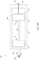
- FIG. 1 illustrates schematically a locking suture deployed within a target region for approximating tissues therein, according to an embodiment.
- FIGS. 2A, 2B, 2C, and 2D illustrate schematically a method and device for approximating tissues using a LS delivery device, according to an embodiment.
- FIGS. 3A, 3B, 3C, and 3D illustrate schematically and conceptually a method of deploying the locking suture of FIGS. 2A-2D .
- FIG. 4 illustrates a cut-away anterior view of a heart, showing the internal chambers, valves and adjacent structures.
- FIG. 5A illustrates a top perspective view of a healthy mitral valve with the mitral leaflets closed.
- FIG. 5B illustrates a top perspective view of a dysfunctional mitral valve with a visible gap between the mitral leaflets.
- FIG. 5C illustrates a cross-sectional view of a heart illustrating a mitral valve prolapsed into the left atrium.
- FIG. 5D illustrates an enlarged view of the prolapsed mitral valve of FIG. 5C .
- FIG. 6 illustrates a cross-sectional view of a heart showing the left atrium, right atrium, left ventricle, right ventricle and the apex region.
- FIG. 7 illustrates a block diagram of an example LS delivery device having a knot holder and atraumatic tip with a tensioner and release mechanism.
- FIG. 8 illustrates a flow chart of an example method for securing a locking suture to approximate distal anchors attached to tissue
- FIG. 9 is a schematic illustration of a mitral valve with leaflets that are separated by a gap.
- FIGS. 10A, 10B, 10C, and 10D illustrate a method using a LS delivery device to deliver and deploy a locking suture, according to an embodiment.
- FIGS. 11A, 11B, 11C, 11D, 11E, 11F, and 11G illustrate a method of forming a knot portion of a locking suture about a knot holder, according to an embodiment.
- FIGS. 12A, 12B, 12C, 12D, and 12E illustrate an alternate approach for forming the locking suture knot portion of FIGS. 11A-11G .
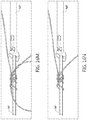
- FIG. 13 illustrates in right side view a LS delivery device, according to an embodiment.
- FIG. 14 illustrates in left side view the LS delivery device of FIG. 13 .
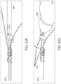
- FIGS. 15A and 15B illustrate detailed top views of the knot pusher of the LS delivery device of FIG. 13 with a knot holder in an extended position and a retracted position, respectively.
- FIG. 15C illustrates a detailed side view of the knot pusher of the LS delivery device of FIG. 13 with a knot holder in an extended position.
- FIG. 15D illustrates a detailed front view of the knot pusher of the LS delivery device of FIG. 13 with a knot holder in disposed within the lumen of the knot pusher.
- FIG. 15E illustrates a detailed perspective view of the knot pusher, the knot end effector, and the knot holder extending distally therefrom.
- FIG. 15F illustrates a detailed front view version of FIG. 15E .
- FIG. 15G illustrates a detailed bottom perspective view version of FIG. 15E .
- FIG. 15H illustrates a detailed top view version of FIG. 15E .
- FIG. 15I illustrates a detailed front perspective view version of FIG. 15E .
- FIGS. 16A, 16B, 16C, 16D, 16E, 16F, 16G, 16H, 16I, 16J, 16K, 16L, 16M, 16N, 160, 16P, 16Q, 16R, 16S, 16T, 16U , 16 V, 16 W, 16 X, 16 Y, 16 Z, 16 AA, 16 AB, 16 AC, 16 AD, 16 AE, 16 AF, 16 AG, 16 AH, 16 AI, 16 AJ, and 16 AK illustrate a method of preparing the locking suture of the LS delivery device of FIG. 13 for delivery and deployment.
- FIG. 16AL illustrates the locking suture of FIGS. 16A-16AK deployed and secured to sutures extending from implants.
- FIGS. 17A, 17B, 17C, 17D, 17E, 17F, 17G, 17H, 17I, 17J, 17K, 17L, 17M, 17N, 170, 17P, 17Q, 17R, 17S, 17T, 17U , 17 V, and 17 W illustrate an alternate method of forming the locking suture described with reference to FIGS. 16A-16AK .
- FIGS. 18A, 18B, 18C, 18D, 18E, 18F, 18G, 18H, 18I, 18J, 18K, 18L, and 18M illustrate another example LS delivery device with a tensioning mechanism that includes a rack and pinion configuration.
- FIG. 19 illustrates a flowchart of an example method of delivering and deploying a locking suture to approximate mitral valve leaflets, according to an embodiment.
- FIG. 20 illustrates a locking suture disposed about a knot holder in an elongated configuration, according to an embodiment.
- FIG. 21 illustrates the locking suture of FIG. 20 in a deployed knot configuration.
- FIGS. 22A, 22B, and 22C illustrate an edge-to-edge procedure for a mitral valve using the locking sutures and delivery devices described herein.
- the ability to remotely (e.g., from outside the heart during a cardiac valve repair) and adjustably secure two or more otherwise separate strands of suture together within a body has wide ranging applications.
- One application for example, is in minimally-invasive, beating-heart, cardiac procedures.
- the ability to remotely secure two or more suture strands together while the heart is beating should dramatically expand the utility of the devices that have been used in cardiac operations to date.
- a method for repairing tissue includes inserting a delivery device, such as a delivery device described in the '761 PCT Application and/or in International Patent Application No. PCT/US2016/055170 (published as WO 2017/059426A1 and referred to herein as “the '170 PCT Application”), the entire disclosure of each of which is incorporated herein by reference, into a body and extending a distal end of the delivery device to a proximal side of the tissue. Advancement of the delivery device may be performed in conjunction with sonography or direct visualization (e.g., direct transblood visualization), and/or any other suitable remote visualization technique.
- a delivery device such as a delivery device described in the '761 PCT Application and/or in International Patent Application No. PCT/US2016/055170 (published as WO 2017/059426A1 and referred to herein as “the '170 PCT Application”), the entire disclosure of each of which is incorporated herein by reference, into a body and extending a
- the delivery device may be advanced in conjunction with transesophageal (TEE) guidance or intracardiac echocardiography (ICE) guidance to facilitate and to direct the movement and proper positioning of the device for contacting the appropriate target cardiac region and/or target cardiac tissue (e.g., a valve leaflet, a valve annulus, or any other suitable cardiac tissue).
- TEE transesophageal
- ICE intracardiac echocardiography
- target cardiac tissue e.g., a valve leaflet, a valve annulus, or any other suitable cardiac tissue.
- Typical procedures for use of echo guidance are set forth in Suematsu, Y., J. Thorac. Cardiovasc. Surg. 2005; 130:1348-56 (“Suematsu”), the entire disclosure of which is incorporated herein by reference.
- a piercing portion of the delivery device can be used to form an opening in the tissue, through which the distal end of the delivery device can be inserted.
- the delivery device can be used to form or deliver an implant (e.g., a distal anchor) to the distal side of the tissue.
- the delivery device can be used in this manner to deliver two or more implants to the distal side of the tissue.
- the implants can be delivered to a single tissue (e.g., a posterior mitral valve leaflet), or one or more implants can be delivered to a first tissue (e.g., a posterior mitral valve leaflet), and one or more other implants can be delivered to a second tissue (e.g., an anterior mitral valve leaflet, a mitral valve annulus, or any other suitable tissue) separate from the first tissue.
- the delivery device can then be withdrawn, and suture portions extending from the implants can extend to a location (e.g., an outside surface of the heart or other suitable organ) remote from the tissue(s).
- the remote suture portions can then be coupled to a locking suture delivery and deployment device (also referred to as a locking suture device or locking suture delivery device) that can be operated from outside the target region to deliver and to deploy a locking suture within the targeted region about the suture portions extending from the tissue(s).
- a locking suture delivery and deployment device also referred to as a locking suture device or locking suture delivery device
- introducing additional foreign objects, such as, for example, a securing device to an area within the target region (e.g., the heart) within which the tissues are located, can be avoided.
- the locking suture device can remain outside the heart and can be used to selectively and remotely secure the suture portions extending from the implants and to selectively, reversibly, and controllably approximate the tissue(s) from which the suture portions extend.
- one or more pairs of sutures can be used to secure the annuloplasty ring around the mitral annulus.
- the suture pairs may be joined using embodiments of the devices and methods disclosed herein.
- a procedure e.g., a mitral valve repair
- an anchor e.g., a pledget
- knotting, joining, securing, and/or approximating multiple sutures together may be useful in minimally invasive thoracic and/or abdominal surgeries where, for example, there is restrictive or limited space (e.g., when working through relatively small trocar portal(s)).
- Another example includes using sutures to restrict or cut off blood flow in a damaged blood vessel, such as in the brain.
- the disclosed locking sutures, devices, and methods can be used to secure sutures in a way that restricts blood flow through targeted blood vessels.
- FIG. 1 illustrates schematically an example of a locking suture 137 deployed within a target region TR for approximating tissues T 1 , T 2 therein.
- the locking suture 137 includes a knot portion 137 A configurable between a delivery configuration and a deployed configuration, and a tether portion 137 B extending from the knot portion 137 A and configured to be manipulated outside the target region TR to transition the knot portion 137 A within the target region TR from its delivery configuration to its deployed configuration.
- the locking suture 137 can be secured within the target region TR to both the first suture portion 132 and the second suture portion 134 , and can be anchored to a location outside the target region TR.
- translating or moving the locking suture 137 distally and/or proximally along the free ends of the sutures 132 , 134 can change the distance between the implants 131 , 131 ′ and therefore the tissues T 1 , T 2 .
- the locking suture 137 can be locked by transitioning the knot portion 137 A from its delivery configuration to its deployed configuration using the tether portion 137 B.
- the locking suture 137 can be formed of any suitable material.
- the locking suture can made of one or more of expanded polytetrafluoroethylene (“ePTFE”) suture, polybutylate-coated polyester suture, or polyester suture (such as, for example, Ethibond Excel® Polyester Suture, Johnson & Johnson, New Brunswick, N.J.).
- ePTFE expanded polytetrafluoroethylene
- polyester suture such as, for example, Ethibond Excel® Polyester Suture, Johnson & Johnson, New Brunswick, N.J.
- the locking suture can be modified to increase its coefficient of friction to improve its locking capability.
- the locking suture, made from ePTFE for example, can be braided, twisted, or knotted (e.g., with overhand knots).
- the locking suture's thickness and/or surface texture e.g., textured surface, coating, etc.
- the implants 131 , 131 ′ can be delivered and disposed on an atrial, distal, or top side of heart valve leaflets (e.g., mitral valve leaflets).
- the implants 131 , 131 ′ can be formed with a suture material that forms a loop on the atrial, distal, or top side of the leaflets and extends through the leaflets, with two loose suture end portions that extend on the ventricular, proximal, or bottom side of the leaflets.
- implants can be formed separately from and then attached to the suture end portions.
- the implants can be attached to the suture material, deployed on the atrial side of the leaflets, and the suture end portions can extend from the implants and through the leaflets to the ventricular side of the leaflets, and then anchored outside the target region TR (e.g., the heart) as described in further detail herein.
- TR target region
- the knot portion 137 A of the locking suture 137 when in its delivery configuration can be slidably coupled to and delivered (e.g., pushed distally) along the suture portions 132 , 134 into and through the target region TR using a delivery device that is operated from outside the target region TR (e.g., controlled remotely and delivered minimally invasively).
- the knot portion 137 A can be in the form of braided, twisted, coiled, looped, and/or knotted lines (e.g., sutures). In a delivery configuration, the knot portion 137 A can be loose enough to allow a plurality of sutures to slide therethrough.
- the knot portion 137 A can be constricted to create a tortuous path for the plurality of sutures passing through the knot portion.
- the knot portion 137 A can be in the form of one or more multi-turn coils distributed about various regions of the suture portions 132 , 134 , and the coils can be changed from an elongated, delivery configuration, in which the knot portion 137 A is slidable, translatable, and/or pushable along or about the suture portions 132 , 134 while maintaining its integrity (e.g., its coiled formation), to a deployed configuration by constricting the coils and/or approximating opposite ends of the coil(s) towards each other to lock or secure the knot portion 137 A to the suture portions 132 , 134 and inhibit relative motion therebetween.
- the tether portion 137 B can be pulled proximally. This causes the knot portion 137 A to constrict on the suture portions 132 , 134 so that they are secured together within the knot portion 137 A at a targeted location within the target region TR relative to the tissues T 1 , and T 2 .
- the knot portion 137 A can be secured in a way that the knot portion 137 A does not move distally or proximally along the suture portions 132 , 134 .
- the free ends of the suture portions 132 , 134 and the free ends of the tether portion 137 B extend to a location outside the target region TR.
- the tether portion 137 B and the free ends of the suture portions 132 , 134 can be coupled to and secured outside the target region TR using a proximal anchor 144 .
- the tether portion 137 B and the free ends of the suture portions 132 , 134 can be secured via the proximal anchor 144 to an external or outer surface of a tissue, such as the heart.
- FIGS. 2A, 2B, 2C, and 2D illustrate schematically examples of a method and a device for approximating tissues T 1 , T 2 (e.g., mitral valve leaflets within a heart) by delivering and deploying a locking suture 237 using a locking suture (LS) delivery device 246 .
- LS locking suture
- a user can control or manipulate the LS delivery device 246 from outside the target region TR to deliver and to deploy the locking suture 237 within the target region TR.
- FIG. 2A illustrates a first suture portion 232 extending from a first implant 231 secured to a first tissue T 1 and a second suture portion 234 extending from a second implant 231 ′ secured to a second tissue T 2 .
- the first suture portion 232 and the second suture portion 234 can extend to a location remote from the tissues T 1 , T 2 (e.g., an outer surface of the heart), and can be operably coupled to the LS delivery device 246 outside the target region TR.
- the first and second suture portions 232 , 234 can be passed through the locking suture 237 that is coupled to an end of the LS delivery device 246 .
- first and second suture portions 232 , 234 can be threaded through portions of the locking suture. In some embodiments, the first and second suture portions 232 , 234 can pass through a central portion of the locking suture 237 (e.g., a lumen formed by one or more coils of the locking suture 237 ).
- a central portion of the locking suture 237 e.g., a lumen formed by one or more coils of the locking suture 237 .
- each suture portion 232 , 234 is coupled to the LS delivery device 246 remote from the tissues T 1 , T 2 and is outside the target region TR, the LS delivery device 246 can deliver and deploy the locking suture 237 within the target region TR to approximate the tissues T 1 , T 2 .
- FIG. 2B illustrates inserting a portion of the LS delivery device 246 into the target region TR to move the locking suture 237 to a targeted location.
- actuation of the LS delivery device 246 can operate (1) to deliver the locking suture 237 in its delivery configuration, and (2) to transition the locking suture 237 into its deployed configuration.
- the knot portion 237 A of the locking suture 237 is able to slide or translate along, or otherwise move relative to, the suture portions 232 , 234 , to a targeted location within the target region TR.
- the knot portion 237 A of the locking suture 237 is tightened, compressed (e.g., radially and/or laterally), cinched, or otherwise secured to the suture portions 232 , 234 .
- the LS delivery device 246 is used to push, urge, slide, translate or otherwise move the knot portion 237 A in its delivery configuration distally along the suture portions 232 , 234 within the target region TR. Movement of the knot portion 237 A can be along a translation axis 247 that is preferably, but not necessarily, oriented between the axes of the suture portions 232 , 234 . In some embodiments, the axis 247 may approximately bisect the angle ⁇ defined between the axes of the suture portions 232 , 234 .
- the suture portions 232 , 234 define a point of intersection 299 of the axes of the suture portions 232 , 234 .
- the point of intersection 299 is moved towards the implants 231 , 231 ′ (and thus the tissues T 1 , T 2 ), the lengths of the suture portions 232 , 234 between the point of intersection 299 and the respective tissues T 1 , T 2 shorten, and the angle ⁇ defined between the axes of the suture portions 232 , 234 increases.
- the tether portion 237 B can be pulled proximally or withdrawn to deploy the knot portion 237 A. Deployment of the knot portion 237 A inhibits relative movement between the knot portion 237 A and the suture portions 232 , 234 disposed therein.
- pulling the tether portion 237 B does not significantly increase or alter the tension on the suture portions 232 , 234 and, consequently, the force or tension on the distal anchors 231 , 231 ′ and the tissue T 1 , T 2 does not significantly change during deployment of the knot portion 237 A.
- the force or tension applied to the tether portion 237 B that causes the knot portion 237 A to deploy is directed to the knot portion 237 A at the distal tip of the LS delivery device 246 and not to the distal anchors 231 , 231 ′ or the tissues T 1 , T 2 .
- the suture portions 232 , 234 , the distal anchors 231 , 231 ′, and/or the tissues T 1 , T 2 can be free from any additional tension or force applied when deploying the knot portion 237 A. This may be due at least in part to the design of the distal end of the LS delivery device 246 .
- the distal tip of the LS delivery device 246 can include one or more features that angle the tether portion 237 B at a desired angle so that stress applied to the tether portion 237 B causes the knot portion 237 A to constrict or tighten while not applying significant proximal force that may cause the knot portion 237 A to pull proximally on the suture portions 232 , 234 .
- FIG. 2C illustrates the locking suture 237 in its deployed configuration, secured to the first and second suture portions 232 , 234 .
- the LS delivery device 246 can be withdrawn proximally (e.g., along the suture portions 232 , 234 extending proximally from the locking suture 237 ) and removed from the target region TR. Removing the LS delivery device 246 leaves behind the deployed locking suture 237 secured to the suture portions 232 , 234 at a targeted location within the target region TR.
- the targeted location can be selected or based on a targeted approximation of tissues T 1 , T 2 and/or a targeted amount of tension applied by the suture portions 232 , 234 to the tissues T 1 , T 2 .
- the free ends of the suture end portions 232 , 234 and the free ends of the tether portion 237 B can extend from the deployed locking suture 237 within the target region TR to an area outside the target region TR. These ends can be secured via a proximal anchor 244 outside the target region TR (e.g., against an outer surface of the heart).
- a force, F applied to the locking suture 237 and/or to the two suture portions 232 , 234 (and considering each suture portion 232 , 234 as a pure tension member), results in an axial force, Fs, carried by each suture portion 232 , 234 between the knot portion 237 A and the tissues T 1 , T 2 along the respective axes of the suture portions 232 , 234 .
- Each axial force, Fs can be decomposed into a first component, Fa, that is parallel to the axis 247 that bisects the angle ⁇ and a second component, Fb, that is perpendicular to the axis 247 .
- the second component, Fb, of the axial force, Fs, in each suture portion 232 , 234 acts to approximate, or draw together, the tissue T 1 , T 2 to which the implants 231 , 231 ′ are coupled.
- the LS delivery device 246 can be used to slide the knot portion 237 A distally or proximally along the suture portions 232 , 234 to change the angle ⁇ and the location of the point of intersection 299 . For example, pushing the knot portion 237 A distally approximates the implants 231 , 231 ′. Similarly, pulling the knot portion 237 A proximally reduces the amount of approximation of the implants 231 , 23 P. For example, the LS delivery device 246 can be withdrawn (e.g., when in its delivery configuration) proximally before the locking suture 237 is deployed to withdraw the knot portion 237 A proximally to reduce the approximation of the implants 231 , 231 ′.
- the degree of approximation can be increased or decreased until the desired or targeted approximation is achieved.
- the targeted degree of approximation can be confirmed under image guidance (e.g., echocardiography).
- the LS delivery device 246 can then be actuated to transition the knot portion 237 A of the locking suture 237 from its delivery configuration to its deployed configuration to lock, radially and/or laterally compress (described in more detail herein), and/or otherwise secure the locking suture 237 in place relative to the suture portions 232 , 234 . This results in the degree of approximation of the implants 231 , 231 ′ being substantially secured and maintained after the LS delivery device 246 is removed.
- the LS delivery device 246 can then be withdrawn from the target region TR and decoupled or withdrawn from the suture portions 232 , 234 and the tether portion 237 B.
- the suture portions 232 , 234 and the free ends of the locking suture 237 can be secured outside the target region TR in a suitable location (e.g., an outer surface of the heart) with, for example, a proximal anchor 244 .
- the knot portion 237 A has (1) a delivery configuration in which the locking suture 237 is pushable, slidable or deliverable along or about the suture portions 232 , 234 , and (2) a deployed configuration in which the knot portion 237 B is further engaged with, further constricted about, compressed (e.g., radially and/or laterally), cinched, secured, tightened, or fixed to the suture portions 232 , 234 , such that relative motion between the knot portion 237 A and a portion of the suture portions 232 , 234 is inhibited and/or prevented.
- a delivery configuration in which the locking suture 237 is pushable, slidable or deliverable along or about the suture portions 232 , 234
- a deployed configuration in which the knot portion 237 B is further engaged with, further constricted about, compressed (e.g., radially and/or laterally), cinched, secured, tightened, or fixed to the suture portions 232 , 234 , such that relative
- the knot portion 237 A is wrapped, intertwined, looped, turned, wound, or otherwise engaged with the suture portions 232 , 234 in a manner that allows the locking suture 237 to maintain its structural integrity (e.g., its coiled disposition) such that it is in a ready-state to be deployed, while allowing sufficient relative movement between the locking suture 237 and the suture portions 232 , 234 .
- This allows the knot portion 237 A to be moved distally and/or proximally along the suture portions 232 , 234 .
- FIGS. 3A-3D conceptually illustrate a segment of the knot portion 237 A of FIGS. 2A-2D disposed about the suture portions 232 , 234 as it transitions from a delivery configuration to a deployed configuration.
- transitioning to the deployed configuration is presented as having a number of sequential stages, however, it is to be understood that the stages or portions of the stages may occur simultaneously or in a different order.
- FIG. 3A illustrates the segment of the knot portion 237 A in the delivery configuration disposed about the suture portions 232 , 234 .
- FIG. 3B illustrates the segment of the knot portion 237 A in a first stage of the deployed configuration where the knot portion 237 A experiences radial compression.
- FIG. 3C illustrates the segment of the knot portion 237 A in a second stage of the deployed configuration where the knot portion 237 A experiences lateral compression.
- FIG. 3D illustrates the segment of the knot portion 237 A in a different second stage of the deployed configuration that is limited to axial compression of the knot portion 237 A.
- the locking functionality of the knot portion 237 A can be decomposed into multiple locking portions that individually provide forces against the suture portions 232 , 234 disposed therebetween.
- a first portion 237 A- 1 provides a first force component Fa 1
- a second portion 237 A- 2 provides a second force component Fb 1
- a third portion 237 A- 3 provides a third force component Fc 1 .
- the three portions 237 A- 1 , 237 A- 2 , 237 A- 3 and their respective associated force components Fa 1 , Fb 1 , Fc 1 represent example locations from which forces are applied by the knot portion 237 A of the locking suture 237 .
- the knot portion 237 A can provide circumferentially continuous compressive, constrictive, or locking force components or vectors about the suture portions 232 , 234 , as more clearly evident in embodiments described herein.
- the arrow A represents a direction of allowable movement or translation of the suture portions 232 , 234 relative to the knot portion 237 A when in the delivery configuration. That is, in the delivery configuration the locking suture 237 is sufficiently loosely wound, wrapped, and/or coiled around the suture portions 232 , 234 in an elongated manner that the locking suture 237 can be moved along the suture portions 232 , 234 . This can be done, for example, to deliver the locking suture 237 into the target region TR and towards the tissues T 1 , T 2 (which is described in greater detail herein with reference to FIGS. 2A and 2B ).
- the locking suture 237 With the knot portion 237 A delivered to a targeted location, the locking suture 237 can be deployed or transitioned into a tightened, bulky, bunched, or looped knot configuration. This can be accomplished, for example, by approximating opposite ends of the winds or coils of the locking suture 237 towards each other.
- the coils, wraps, loops, turns, or portions of the knot portion 237 A disposed about the suture portions 232 , 234 are tightened, shortened, and/or constricted, resulting in a restrained or confined tortuous path for the suture portions 232 , 234 , as illustrated conceptually in FIGS. 3B, 3C, and 3D .
- FIGS. 3B, 3C, and 3D With reference to FIG.
- the magnitude of the force components Fa 2 , Fb 2 , Fc 2 applied by the respective portions 237 A- 1 , 237 A- 2 , 237 A- 3 of the knot portion 237 A in the first stage of its deployed configuration is greater than a magnitude of the force components Fa 1 , Fb 1 , Fc 1 in the delivery configuration shown in FIG. 3A , resulting in the respective locking suture portions 237 A- 1 , 237 A- 2 , 237 A- 3 moving towards the suture portions 232 , 234 , e.g., towards axis B.
- the knot portion 237 A is radially compressed about the suture portions 232 , 234 by opposing forces, e.g., forces Fa 2 and Fc 2 oppose force Fb 2 , thereby increasing the friction between the knot portion 237 A and the suture portions 232 , 234 and restricting relative movement therebetween.
- opposing forces e.g., forces Fa 2 and Fc 2 oppose force Fb 2
- Fb 2 force between the knot portion 237 A and the suture portions 232 , 234 and restricting relative movement therebetween.
- one strand or free end of the tether portion 237 B can be pulled or withdrawn proximally.
- Such radial compression is illustrated by the opposing movements of the first and third locking portions 237 A- 1 237 A- 3 relative to the second locking portion 237 A- 2 .
- a second stage of deployment can include pulling on the other strand or free end of the tether portion 237 B to laterally or angularly deflect the first portion 237 A- 1 (e.g., along arrow C, about the B axis, and/or about the second portion 237 A- 2 ) to create a bulky or looped configuration to further secure and inhibit relative movement of the suture portions 232 , 234 , as illustrated in FIG. 3C .
- FIG. 3C examples of which are illustrated in FIG.
- the second stage of deployment can involve only axial compression of knot portion 237 A, e.g., reducing the axial spacing of first, second, and third locking portions 237 A- 1 , 237 A- 2 , and 237 A- 3 along axis B.
- the free ends of the suture portions 232 , 234 and the tether portion 237 B can be dealt with in any suitable manner.
- the free ends of the suture portions 232 , 234 and the tether portion 237 B can be secured outside the target region (e.g., to an external surface of the heart).
- the methods and devices described herein are readily adaptable for various types of tissue repair procedures.
- embodiments described herein are described with respect to repairing a cardiac mitral valve. It should be understood, however, that the devices and methods described herein can be used to repair other cardiac valves, such as a tricuspid, aortic, or pulmonic valve, or non-valvular cardiac tissue, such as heart walls and/or septa, or non-cardiac tissues, such as in orthopedic applications where two or more tissues are to be approximated.
- the devices and methods described herein can be used in applications in which two or more sutures or the like are to be approximated, knotted, joined, and/or secured together.
- the free ends of the cords may extend outside the heart.
- the devices and methods described herein can be used to secure the cords together outside the heart, and optionally, for example, to a pledget or similar anchor.
- apparatus and methods are described herein for remotely securing two or more sutures together within a non-invasive procedure to repair a cardiac valve.
- apparatus and methods are described herein for performing a non-invasive procedure for repairing a mitral valve using an edge-to-edge stitch (also referred to as an Alfieri procedure) to secure two mitral valve leaflets together.
- the human heart 10 has four chambers, which include two upper chambers denoted as atria 12 , 16 and two lower chambers denoted as ventricles 14 , 18 .
- a septum 20 (see, e.g., FIG. 6 ) divides the heart 10 and separates the left atrium 12 and left ventricle 14 from the right atrium 16 and right ventricle 18 .
- the heart further contains four valves 22 , 23 , 26 , and 27 . The valves function to maintain the pressure and unidirectional flow of blood through the body and to prevent blood from leaking back into a chamber from which it has been pumped.
- the mitral valve 22 also known as the left atrioventricular valve, controls the passage of oxygenated blood from the left atrium 12 to the left ventricle 14 .
- a second valve, the aortic valve 23 separates the left ventricle 14 from the aortic artery (aorta) 29 , which delivers oxygenated blood via the circulation to the entire body.
- the aortic valve 23 and mitral valve 22 are part of the “left” heart, which controls the flow of oxygen-rich blood from the lungs to the body.
- the right atrioventricular valve, the tricuspid valve 24 controls passage of deoxygenated blood into the right ventricle 18 .
- a fourth valve, the pulmonary valve 27 separates the right ventricle 18 from the main pulmonary artery 25 .
- the right ventricle 18 pumps deoxygenated blood through the pulmonary artery 25 to the lungs wherein the blood is oxygenated and then delivered to the left atrium 12 via the pulmonary vein.
- the tricuspid valve 24 and pulmonic valve 27 are part of the right heart, which control the flow of oxygen-depleted blood from the body to the lungs.
- Both the left and right ventricles 14 , 18 constitute pumping chambers.
- the aortic valve 23 and pulmonic valve 27 lie between a pumping chamber (ventricle) and a major artery and control the flow of blood out of the ventricles and into the circulation.
- the aortic valve 23 and pulmonic valve 27 have three cusps, or leaflets, that open and close and thereby function to prevent blood from leaking back into the ventricles after being ejected into the lungs or aorta 29 for circulation.
- Both the left and right atria 12 , 16 are receiving chambers.
- the mitral valve 22 and tricuspid valve 24 therefore, lie between a receiving chamber (atrium) and a ventricle so as to control the flow of blood from the atria to the ventricles and prevent blood from leaking back into the atrium during ejection from the ventricle.
- Both the mitral valve 22 and tricuspid valve 24 include two or more cusps, or leaflets (not shown in FIG. 4 ), that are encircled by a variably dense fibrous ring of tissues known as the annulus (not shown in FIG. 4 ).
- the valves are anchored to the walls of the ventricles by chordae tendineae (chordae) 17 .
- the chordae tendineae 17 are cord-like tendons that connect the papillary muscles 19 to the leaflets (not shown in FIG. 4 ) of the mitral valve 22 and tricuspid valve 24 of the heart 10 .
- the papillary muscles 19 are located at the base of the chordae tendineae 17 and are within the walls of the ventricles.
- the papillary muscles 19 do not open or close the valves of the heart, which close passively in response to pressure gradients; rather, the papillary muscles 19 brace the valves against the high pressure needed to circulate the blood throughout the body.
- the papillary muscles 19 and the chordae tendineae 17 are known as the sub-valvular apparatus.
- the function of the sub-valvular apparatus is to keep the valve leaflets from prolapsing into the atria when they close.
- the mitral valve 22 is illustrated in FIG. 5A .
- the mitral valve 22 includes two leaflets, the anterior leaflet 52 and the posterior leaflet 54 , and a diaphanous incomplete ring around the valve, called the annulus 53 .
- the mitral valve 22 has two papillary muscles 19 , the anteromedial and the posterolateral papillary muscles (see, e.g., FIG. 4 ), which attach the leaflets 52 , 54 to the walls of the left ventricle 14 via the chordae tendineae 17 (see, e.g., FIG. 4 ).
- FIG. 5B illustrates a prolapsed mitral valve 22 .
- prolapse occurs when a prolapsed segment of a leaflet 52 , 54 of the mitral valve 22 is displaced above the plane of the mitral annulus into the left atrium 12 (see FIGS. 5C and 5D ) preventing the leaflets from properly sealing together to form the natural plane or line of coaptation between the valve leaflets during systole. Because one or more of the leaflets 52 , 54 malfunctions, the mitral valve 22 does not close properly, and, therefore, the leaflets 52 , 54 fail to coapt.
- This failure to coapt causes a gap 55 between the leaflets 52 , 54 that allows blood to flow back into the left atrium, during systole, while it is being ejected by the left ventricle.
- a leaflet may malfunction, which can thereby lead to regurgitation.
- Mitral valve regurgitation increases the workload on the heart and may lead to very serious conditions if left untreated, such as decreased ventricular function, pulmonary hypertension, congestive heart failure, permanent heart damage, cardiac arrest, and ultimately death. Since the left heart is primarily responsible for circulating the flow of blood throughout the body, malfunction of the mitral valve 22 is particularly problematic and often life threatening.
- a cardiac valve such as a mitral valve
- procedures include procedures to repair regurgitation that occurs when the leaflets of the mitral valve do not coapt at peak contraction pressures, resulting in an undesired back flow of blood from the ventricle into the atrium.
- a corrective procedure can be performed after the malfunctioning cardiac valve has been assessed and the source of the malfunction verified.
- Various procedures can be performed in accordance with the methods described therein to effectuate a cardiac valve repair, which will depend on the specific abnormality and the tissues involved.
- a transesophageal echocardiogram (2D or 3D)
- a transthoracic echocardiogram TTE
- intracardiac echo ICE
- cardio-optic direct visualization e.g., via infrared vision from the tip of a 7.5 F catheter
- one or more incisions are made proximate to the thoracic cavity to provide a surgical field of access.
- the total number and length of the incisions to be made depend on the number and types of the instruments to be used as well as the procedure(s) to be performed.
- the incision(s) should be made in such a manner to be minimally invasive.
- the term minimally invasive means in a manner by which an interior organ or tissue may be accessed with as little as possible damage being done to the anatomical structure through which entry is sought.
- a minimally invasive procedure is one that involves accessing a body cavity by a small incision of, for example, approximately 5 cm or less made in the skin of the body.
- the incision may be vertical, horizontal, or slightly curved. If the incision is placed along one or more ribs, it should follow the outline of the rib.
- the opening should extend deep enough to allow access to the thoracic cavity between the ribs or under the sternum and is preferably set close to the rib cage and/or diaphragm, dependent on the entry point chosen.
- the heart may be accessed through one or more openings made by a small incision(s) in a portion of the body proximal to the thoracic cavity, for example, between one or more of the ribs of the rib cage of a patient, proximate to the xyphoid appendage, or via the abdomen and diaphragm.
- Access to the thoracic cavity may be sought to allow the insertion and use of one or more thorascopic instruments, while access to the abdomen may be sought to allow the insertion and use of one or more laparoscopic instruments. Insertion of one or more visualizing instruments may then be followed by transdiaphragmatic access to the heart.
- access to the heart may be gained by direct puncture (e.g., via an appropriately sized needle, for instance an 18-gauge needle) of the heart from the xyphoid region.
- the one or more incisions should be made in such a manner as to provide an appropriate surgical field and access site to the heart in the least invasive manner possible. Access may also be achieved using percutaneous methods further reducing the invasiveness of the procedure.
- the surgeon can use one or more sutures to make a series of stiches in one or more concentric circles in the myocardium at the desired location to create a “pursestring” closure.
- the Seldinger technique can be used to access the left ventricle in the area surrounded by the pursestring suture by puncturing the myocardium with a small sharp hollow needle (a “trocar”) with a guidewire in the lumen of the trocar. Once the ventricle has been accessed, the guidewire can be advanced, and the trocar removed.
- a valved-introducer with dilator extending through the lumen of the valved-introducer can be advanced over the guidewire to gain access to the left ventricle.
- the guidewire and dilator can be removed and the valved-introducer will maintain hemostasis, with or without a suitable delivery device inserted therein, throughout the procedure.
- the surgeon can make a small incision in the myocardium and insert the valved-introducer into the heart via the incision. Once the valved-introducer is properly placed the pursestring suture is tightened to reduce bleeding around the shaft of the valved-introducer.
- a suitable device such as a delivery device described in the '761 PCT Application and/or the '170 PCT Application, may be advanced into the body and through the valved-introducer in a manner to access the left ventricle.
- the advancement of the device may be performed in conjunction with sonography or direct visualization (e.g., direct transblood visualization).
- the delivery device may be advanced in conjunction with TEE guidance or ICE to facilitate and direct the movement and proper positioning of the device for contacting the appropriate apical region of the heart.
- Typical procedures for use of echo guidance are set forth in Suematsu.
- one or more chambers e.g., the left atrium 12 , left ventricle 14 , right atrium 16 , or right ventricle 18 in the heart 10 may be accessed in accordance with the methods disclosed herein. Access into a chamber 12 , 14 , 16 , 18 in the heart 10 may be made at any suitable site of entry but is preferably made in the apex region of the heart, for example, slightly above the apex 26 at the level of the papillary muscles 19 (see also FIG. 5C ).
- access into the left ventricle 14 for instance, to perform a mitral valve repair, is gained through the process described above performed in the apical region, close to (or slightly skewed toward the left of) the median axis 28 of the heart 10 .
- access into the right ventricle 18 for instance, to perform a tricuspid valve repair, is gained through the process described above performed in the apical region, close to or slightly skewed toward the right of the median axis 28 of the heart 10 .
- an apex region of the heart is a bottom region of the heart that is within the left or right ventricular region and is below the mitral valve 22 and tricuspid valve 24 and toward the tip or apex 26 of the heart 10 . More specifically, an apex region AR of the heart (see, e.g., FIG. 6 ) is within a few centimeters to the right or to the left of the septum 20 of the heart 10 at or near the level of the papillary muscles 19 .
- the ventricle can be accessed directly via the apex 26 , or via an off-apex location that is in the apical or apex region AR, but slightly removed from the apex 26 , such as via a lateral ventricular wall, a region between the apex 26 and the base of a papillary muscle 19 , or even directly at the base of a papillary muscle 19 or above.
- the incision made to access the appropriate ventricle of the heart is no longer than about, for example, about 0.5 cm.
- access can be obtained using the Seldinger technique described above.
- the mitral valve 22 and tricuspid valve 24 can be divided into three parts: an annulus (see 53 in FIGS. 5A and FB), leaflets (see 52 , 54 in FIGS. 5A and 5B ), and a sub-valvular apparatus.
- the sub-valvular apparatus includes the papillary muscles 19 (see FIG. 4 ) and the chordae tendineae 17 (see FIG. 4 ), which can elongate and/or rupture. If the valve is functioning properly, when closed, the free margins or edges of the leaflets come together and form a tight junction, the arc of which, in the mitral valve, is known as the line, plane, or area of coaptation.
- the procedures described herein are with reference to repairing a cardiac mitral valve or tricuspid valve by the implantation of one or more artificial chordae, the methods presented are readily adaptable for various types of tissue, leaflet, and annular repair procedures.
- the methods described herein can be performed to selectively approximate two or more portions of tissue to limit a gap between the portions.
- the methods herein are described with reference to a mitral valve 22 but should not be understood to be limited to procedures involving the mitral valve.
- FIG. 7 illustrates a block diagram of an example LS delivery device 846 having a knot holder 841 and atraumatic tip 840 with a tensioner 843 and release mechanism 842 .
- the LS delivery device 846 is configured to secure a pre-formed locking suture to allow one or more suture ends to be passed through or interweaved with the locking suture, to maneuver the locking suture with suture ends to a targeted location, to allow the suture ends to be adjusted, to tension the locking suture to lock the suture ends (e.g., to inhibit relative motion between the suture tails and the locking suture), and to release the locking suture in its deployed or locked state.
- the LS delivery device 846 includes the atraumatic tip 840 attached to the knot holder 841 .
- the atraumatic tip 840 can be the most distal component of the LS delivery device 846 so that as the LS delivery device 846 advances the locking suture little or no damage is done to the tissue in the target region, such as a valve leaflet.
- the atraumatic tip 840 can be made of a tissue-friendly material that is pliable and/or relatively dull to prevent or reduce the likelihood of tissue damage when the LS delivery device 846 is in the process of delivering the locking suture to its targeted location.
- the knot holder 841 is configured to secure the locking suture in its pre-deployment or delivery configuration.
- the knot holder 841 can be a needle holder and/or a knot holder, where the needle holder secures a needle that is used to hold or secure the locking suture in place during a portion of a procedure using the locking suture.
- a needle can be used to hold a locking suture while suture tail ends are interweaved or inserted through the locking suture, after which the needle can be removed leaving the locking suture with the suture tail ends in a delivery configuration. An example of this configuration is described herein with reference to FIGS. 18A-18K .
- the knot holder 841 can be configured to push off the locking suture as part of deployment or the transition from a delivery state to a deployed state.
- the knot holder 841 can be configured to pull back the holder so that the locking suture slides off the LS delivery device 846 .
- the knot holder 841 can include an outer tube with a flexible feature at a distal end (where the flexible feature functions as the atraumatic tip 840 ).
- the LS delivery device 846 can secure a loose locking suture or a locking suture in a delivery configuration that allows suture tail ends to be threaded through the locking suture using the knot holder 841 wherein the knot holder includes a needle holder. Once the locking suture and suture tail ends are sufficiently intertwined, the needle holder can be removed leaving the locking suture secured to the flexible distal end of the outer tube for delivery.
- the knot holder 841 secures the knot in place without a tip 840 in such a way that the knot goes before the knot holder 841 , the knot therefore providing protection against tissue damage.
- the knot holder 841 also includes tissue-friendly characteristics so that the knot holder 841 and the atraumatic tip 840 are combined. An example of such a configuration is described herein with reference to FIGS. 18A-18K (see, e.g., FIG. 18J ).
- the LS delivery device 846 includes a tensioner 843 that is configured to apply tension to the ends of the locking suture to transition the locking suture from a delivery configuration to a deployed configuration.
- the transition from the delivery configuration to the deployed configuration includes tightening the locking suture to inhibit relative motion between the locking suture and the suture tail ends.
- components of the tensioner 843 include, but are not limited to, a pinion wheel, a loaded spring, gears, grips to allow manually pulling the locking suture tethers, and the like.
- the tensioner 843 is configured so that, advantageously, application of tension to a knot portion of the locking suture does not alter or increase proximal tension on suture tail ends intertwined with the knot portion.
- the knot holder 841 can be configured so that the tensioner 843 applies force to a tether portion of the locking suture and the knot holder 841 directs the applied force to cause the knot portion to tighten while not pulling proximally on the suture tail ends. This can be accomplished, at least in part, by fixing the knot portion in place with the knot holder 841 while it is being tightened. This can be accomplished, at least in part, by configuring the knot holder 841 so that it re-directs tension on the tether portion at an angle relative to the knot portion of the locking suture.
- the tensioner 843 can be configured to provide mechanical advantages when tensioning the tethers of the locking suture.
- the tensioner 843 can be configured to provide a targeted tension.
- the tensioner 843 can be configured to prevent or inhibit the application of too much force to prevent over-tensioning the locking suture.
- the tensioner 843 may include one or more sensors configured to determine or measure the amount of tension on the locking suture tethers.
- the tensioner 843 may also include feedback systems or user interface features to indicate when a targeted tension has been achieved (or exceeded). Examples include gauges, readouts, indicator lights (e.g., green, yellow, and red lights), and the like.
- the tensioner 843 may include a mechanism for allowing a user to dial, set, or enter a targeted tension. The tensioner 843 can then provide that targeted tension to improve repeatability and reliability of the LS delivery device 846 .
- the tensioner 843 can be a multi-stage device that provides forces at different times.
- the tensioner 843 can be configured to sequentially tension or apply force to the ends of the locking suture.
- the tensioner 843 can be configured to apply a first force to a first locking suture end (e.g., a first tether) and at a later time to apply a second force to a second locking suture end (e.g., a second tether).
- the tensioner can be configured to apply a targeted force to each tether of the locking suture to achieve a targeted locking force on the suture tail ends.
- the tensioner 843 is configured to apply at least about 5 N and/or less than or equal to about 40 N, at least about 7 N and/or less than or equal to about 35 N, or at least about 10 N and/or less than or equal to about 30 N on an individual tether of the locking suture.
- the locking suture prior to deployment, can be configured to slide along the suture tails with the application of at least 3 N of force and/or less than or equal to about 13 N of force, at least 4 N of force and/or less than or equal to about 10 N of force, or at least 5 N of force and/or less than or equal to about 7.5 N of force.
- the LS delivery device 846 also includes a release mechanism 842 .
- the release mechanism 842 is configured to cause the knot holder 841 to release the locking suture after it has transitioned to a deployed state.
- the release mechanism 843 is configured to interface or interact with the tensioner 843 and/or the knot holder 841 to cause these components to release the locking suture.
- the release mechanism 842 can be manually activated by a user or it can be configured to automatically release the locking suture after the locking suture has been tightened by the tensioner.
- the release mechanism 842 includes one or more user interface features to allow the user to control when the release mechanism 843 releases the locking suture and suture tail ends.
- FIG. 8 illustrates a flow chart of an example method 900 for securing a locking suture to approximate distal anchors attached to tissue.
- the method 900 can be used with any of the LS delivery devices disclosed herein.
- the method 900 can be used to approximate any tissue that can receive an anchor implant (e.g., a bulky knot implant) with a suture attached thereto. Examples provided herein focus on implanting artificial tendineae, but other procedures may utilize the method 900 .
- an anchor refers to any suitable component or element that serves to anchor a suture to tissue such as, for example and without limitation, hooks, barbs, knots (e.g., bulky knots), and the like.
- the method 900 improves upon existing Alfieri procedures by sliding a locking suture to adjust the tension and direction of force vectors applied to tissues to be approximated.
- the method 900 allows an operator (e.g., a physician or surgeon) a way to change force vectors applied by anchor implants in tissue.
- an operator e.g., a physician or surgeon
- the knot that coalesces a plurality of the sutures or cords can be adjusted to be at any location from the apex of the heart to the valve with the implanted cords. This can be used to adjust both the angle of the force vectors as well as the magnitude of the force vectors, providing increased control to the operator.
- two or more artificial cords are attached to targeted tissue.
- the artificial cords include anchor implants at a distal end that are anchored to the targeted tissue, e.g., a posterior or anterior leaflet.
- the cords also include sutures extending proximally from the anchor implants. These sutures extend proximally from the implants to a region away and/or outside of the targeted region.
- the targeted region is within the heart or within a chamber of the heart (e.g., the left ventricle).
- the proximal ends or portions of the sutures are threaded through a pre-formed locking suture.
- the sutures can be threaded through various strands of the locking suture or the sutures can be threaded through a central lumen or corridor of the locking suture.
- the locking suture can be attached or secure to a LS delivery device, such as any of the LS delivery devices described herein.
- the LS delivery device can be configured to deploy and release the locking suture after approximation of the targeted tissue.
- the pre-formed locking suture can be any of the locking sutures described herein.
- the pre-formed locking suture includes a knot formed from a suture wherein the knot includes a plurality of cow hitches with ends of the knot suture being threaded through portions of the plurality of cow hitches so that, when the ends of the knot suture are tensioned, they axially and radially constrict to create a tortuous path for any suture tail ends threaded through the locking suture. In this way, the suture tail ends and the locking suture are inhibited or prevented from relative movement.
- the locking suture with the suture tail ends intertwined is moved along the sutures toward and/or away from the distal anchors and the targeted tissue.
- Moving, sliding, or otherwise translating the locking suture in its delivery configuration can be accomplished using an LS delivery device.
- the device can push and pull the locking suture to a targeted location. This can be monitored and confirmed using various imaging techniques.
- Moving the locking suture towards the targeted tissue causes the implants (and the tissues) to approximate.
- the targeted tissue can be approximated.
- the locking suture proximally e.g., pulling
- the approximation of the tissues can be decreased.
- the LS delivery device allows an operator to control approximation of the distal anchors and, consequently, the targeted tissue.
- the tension of the sutures can be adjusted. This can be done, for example, by pulling proximally on the suture tail ends. This can be done in conjunction with sliding the locking suture to tailor the force vectors on the implants to achieve targeted tissue approximation. For example, sliding the locking suture can be done simultaneously with pulling (or releasing tension) on the sutures to achieve targeted force vectors and/or targeted tissue approximation.
- imaging or other methods are used to verify that the targeted approximation of the tissues has been achieved.
- This feedback step allows the operator to iteratively adjust the position of the locking suture and/or the amount of tension on the sutures (e.g., as provided in optional step 517 ).
- the iterative nature of this portion of the method 900 is illustrated using an arrow that goes from step 920 back to step 915 .
- Imaging methods include cardiac ultrasound and echo guidance, as described herein.
- the locking suture is deployed at step 922 .
- Deployment of the locking suture includes applying tension to individual tethers of the locking suture. As described herein, the tension can be applied at different times (e.g., sequentially) and/or with different forces to achieve sufficient or targeted locking of the locking suture.
- the LS delivery device can be used to tension the locking suture and release it after tensioning.
- the LS delivery device can be configured so that tension applied to individual tethers of the locking suture does not alter or increase the tension on the distal anchors and the targeted tissue.
- the knot portion can be secured in place by the LS delivery device while tension is applied to the tether portion to limit or prevent movement of the knot portion relative to the two or more sutures during deployment of the locking suture.
- the locked sutures are anchored.
- the anchoring step is done to prevent or to reduce the likelihood that the locked sutures will come loose.
- the sutures can be anchored to a tissue wall, such as an external wall of the heart.
- a pledget can be used as the anchor.
- PTFE Teflon®, DuPont, Wilmington, Del.
- felt can be used as an anchor where the felt is attached to the tissue wall.
- the anchor includes a plurality of holes through which the sutures extend. Knots and/or additional locking sutures can be used to anchor the sutures.
- the locking suture is configured to be able to be moved or slid from outside of the target region. This can allow greater accessibility and flexibility to operators performing the procedure.
- Another advantage of the method 900 is that it is adjustable. The method 900 also allows for real-time adjustment of tissue approximation to achieve coaptation between leaflets because an operator can adjust the tension of the sutures, and by extension the approximation of the implants and targeted tissue, based on feedback from a visualization system (e.g., cardiac ultrasound).
- a visualization system e.g., cardiac ultrasound
- the method 900 also provides other advantages over other approaches to addressing MR. For example, implanting a clip in the mitral valve to address MR does not provide adjustability. In contrast, the method 900 allows for real-time adjustability. Furthermore, the method 900 can be accomplished using real-time imaging or other feedback to reduce or eliminate MR. This allows an operator to see the effects of the procedure in real time allowing for the operator to make adjustments to achieve targeted results. In addition, if reoperation is required the valve is unaffected by the method 900 whereas a mitral valve clip may destroy or damage the tissue. Furthermore, a mitral valve clip is a relatively large amount of hardware to implant in the heart which may increase the risk of embolism and tissue rejection. With the method 900 , the only materials implanted in the body are the sutures which present a significantly lower risk to the patient.
- FIGS. 9 and 10A-10D illustrate schematically a method and delivery device for delivering and deploying a locking suture 337 to secure artificial chordae tendineae that have been implanted as described in the '761 PCT Application and/or the '170 PCT Application.
- FIG. 9 is a schematic illustration of a mitral valve 322 with leaflets 352 , 354 that are separated by a gap 363 .
- two bulky knot implants 331 , 331 ′ are disposed on an atrial, distal, or top side of the leaflets 352 , 354 , respectively.
- the implants 331 , 331 ′ can be formed with a suture material that forms one or more loops on the atrial side of the leaflets 352 , 354 and extends through the leaflets 352 , 354 , with two loose suture end portions that extend on the ventricular, proximal, or bottom side of the leaflets 352 , 354 .
- the implant 331 has suture end portions 332 and 333
- the implant 331 ′ has suture end portions 334 and 335 (not shown in FIG. 9 ).
- a LS delivery device 346 as shown in FIGS. 10A-10D can be used during a procedure to secure the implants 331 , 331 ′ in the desired position and to secure the valve leaflets 352 , 354 in an edge-to-edge relationship.
- the implants 331 , 331 ′ can be secured together to pull or otherwise move the posterior annulus towards the anterior leaflet and/or the anterior annulus towards the posterior leaflet, to reduce the distance between the anterior annulus and the posterior annulus, e.g., the septal-lateral distance by about 10%-40%. Approximating the anterior annulus and the posterior annulus in this manner can decrease the valve orifice, and thereby decrease, limit, or otherwise prevent undesirable regurgitation.
- This technique can be valuable in both degenerative MR with a prolapsed leaflet where the annulus is dilated and in functional MR where the leaflet function is normal but the annulus has dilated and there is a gap between the leaflets that can be closed by approximating the tissue.
- the following example locking suture deployment sequence in connection with FIGS. 10A-10D is shown and described using only two suture portions 332 , 334 .
- the locking suture can be deployed about and secured to any suitable number of suture portions.
- four suture portions e.g., sutures portions 332 , 333 , 334 , 335
- the locking suture can be deployed about and/or secured to more than four suture portions (e.g., six or more suture portions).
- the LS delivery device 346 includes a distal end portion 340 , a medial portion 338 , and a proximal end portion 336 .
- Disposed on the distal end portion 340 is a knot end effector 333 that extends from a distal end portion 340 of an elongated knot pusher tube 347 (also referred to herein as “knot pusher”).
- the knot end effector 333 provides a surface against which and/or a volume within which a knot portion 337 A of the locking suture 337 can be deployed.
- a proximal end portion of the knot pusher 347 is coupled to a handle 335 at the proximal end portion 336 of the LS delivery device 346 . Coupled to and included at least partially within the handle 335 is a proximal end portion of the knot pusher 347 coupled to a pusher hub 357 , an inner elongate member 341 (also referred to herein as “pre-formed knot holder” or “knot holder”) coupled to an inner elongate member hub 351 (also referred to herein as “knot holder hub”), and a locking suture catch 367 (also referred to herein as “LS catch”).
- the knot holder hub 351 is disposed proximal to the knot pusher hub 357 and distal to the LS catch 367 .
- the knot holder 341 is movably disposed within a lumen of the knot pusher 347 .
- the locking suture 337 is coupled to the LS catch 367 and extends through a lumen of the knot holder 341 and a lumen of the knot pusher 347 and is formed into a coiled configuration (e.g., the knot portion 337 A) at the distal end portion 340 of the LS delivery device 346 .
- the knot portion 337 A of the locking suture 337 is disposed about the distal end portion of the knot holder 341 and distal to the knot pusher 347 , and the tether portion 337 B of the locking suture 337 extends from the knot portion 337 through the lumen of the knot pusher 347 and coupled to the LS catch 367 within the handle 335 .
- the LS catch 367 can be configured to releasably hold or secure the tether portion 337 B during delivery and deployment of the knot portion 337 A as described in more detail below.
- the LS catch 367 can hold the tether portion 337 B with a friction fit or with a clamping force and can have a lock that can be released after the knot portion 337 A has been deployed.
- the knot portion 337 A can be in the form of one or more multi-turn coils, winds, and/or cow hitches of the locking suture 337 that can be changed from an elongated configuration during delivery (see, e.g., FIGS.
- FIG. 10D a deployed configuration (e.g., tightened, bulky, bunched, or looped knot; see, e.g., FIG. 10D ) by tightening, constricting, and/or shrinking the multi-turn coils or winds, and/or approximating opposite ends of the winds or coils towards each other.
- a deployed configuration e.g., tightened, bulky, bunched, or looped knot; see, e.g., FIG. 10D
- tightening, constricting, and/or shrinking the multi-turn coils or winds and/or approximating opposite ends of the winds or coils towards each other.
- the coils, wraps, loops, turns, or portions of the knot portion 337 A disposed about the suture portions 332 , 334 are tightened, shortened, and/or constricted, and/or looped resulting in a restrained or confined tortuous path for the suture portions 332 , 334 sufficient to inhibit relative motion between the knot portion 337 A and the regions of the suture portions 332 , 334 intertwined therewith.
- the free ends of the suture portions 332 , 334 extending from the implants 331 , 331 ′ inside the heart and through an incision in the apex region of the heart, for example, can be threaded, woven, and/or routed through the turns or winds of the knot portion 337 A, e.g., in FIG. 8B .
- the LS delivery device 346 in some instances may be pre-loaded with one or more wire threaders (not shown in this embodiment) to assist an operator (e.g., a surgeon) with threading the suture portions 332 , 334 through various regions of the knot portion 337 A in a desired and/or predefined configuration to maximize post-deployment securement between the suture portions 332 , 334 and the locking suture 337 .
- wire threaders not shown in this embodiment
- the free ends of the suture portions 332 , 334 can be releasably held by the operator and/or releasably fixed or secured to a suitable component (e.g., to a portion of the knot pusher 347 ).
- a suitable component e.g., to a portion of the knot pusher 347 .
- the distal end portion 340 , and in some instances the medial portion 338 , of the LS delivery device 346 can be moved distally through the incision (through which the suture portions 332 , 334 extend from the heart) and into the left ventricle of the heart.
- the knot portion 337 A can be advanced along or about the suture portions 332 , 334 and towards the tissues until the knot portion 337 A reaches a desirable location and/or the tissues are desirably approximated.
- the knot holder hub 351 can be withdrawn within and relative to the handle 335 (in the direction of arrow B) and/or the knot pusher hub 357 can be pushed or moved distally within and relative to the handle 335 (in the direction of arrow A) to displace the knot portion 337 A off and/or from the knot holder 341 , leaving the knot portion 337 A separate from the knot holder 341 and on the distal side of the knot pusher 351 , as shown in FIG. 10C .
- knot portion 337 B there can be some slack in the length of tether portion 337 B to allow the knot portion 337 A to slide off the knot holder 341 before deploying. With the knot portion 337 A displaced from the knot holder 341 , the knot portion 337 is ready to be deployed about the suture portions 332 , 334 threaded therethrough.
- the knot holder hub 351 and the LS catch 367 , and thereby the tether portion 337 B of the locking suture 337 can be withdrawn proximally within and relative to the handle 335 (in the direction of arrow C), causing the knot portion 337 A to transition from its delivery configuration to its deployed configuration, as shown in FIG. 10D .
- the LS catch 367 and the knot holder hub 351 are shown and described as being withdrawn within the handle 335 together, in other embodiments, the LS catch 367 can be withdrawn proximally relative to the knot holder hub 351 to deploy the knot portion 337 A of the locking suture 337 .
- the suture portions 332 , 334 can be released by the operator, and the tether portion 337 B can be released from the LS catch 367 , and the LS delivery device 346 can be withdrawn proximally in the direction of arrow D, leaving the deployed knot portion 337 A within the heart, and free ends of the suture portions 332 , 334 and the free ends of the tether portion 337 B extending out of the heart.
- the LS delivery device 346 can be slid over the two lengths of the suture portions 332 , 334 for removal.
- the locking suture, and particularly the knot portions described herein can be formed in any suitable formation such that the locking suture can be suitably delivered and deployed in various expected environments, and that when deployed with portions of one or more sutures (e.g., suture portions 332 , 333 , 334 , 335 ) threaded therethrough, the deployed knot portion will secure and/or inhibit relative movement between the deployed knot portion and the sutures disposed or captured therein.
- securing or inhibiting relative movement can promote a desirable approximation of the tissues attached to the deployed knot portion via the suture portions.
- knot portion When disposed about the knot holder, unraveling of the knot portion can be inhibited or prevented during delivery to a target region.
- the knot portion can be assembled about the knot holder without fastening or retaining means (e.g., retaining clips or bands) to hold the knot portion in place without unraveling, thus promoting more efficient assembly.
- retaining means e.g., retaining clips or bands
- suture portions extending from the tissues can glide or be threaded through the winds or coils of the knot portion with minimal resistance to promote efficient assembly.
- the knot portion When deployed about the suture portions, the knot portion inhibits relative movement therebetween, and the knot portion retains this deployed state in part in response to tensile loading applied to its tether portion (e.g., the tether portion is pulled and anchored to an outer surface of the heart at a desirable tension). Slack or loose coils or winds in the knot portion from assembly to delivery and deployment can be inhibited or prevented.
- the knot portion is suitably slidable along or about the suture portions during delivery, including outside the target region or patient (e.g., in a relatively dry environment) and inside the target region or patient (e.g., in a relatively wet environment, such as, for example, within a beating heart).
- the knot portion is deliverable through an introducer or delivery catheter without being compromised (e.g., unraveling; damaged, or any other undesirable consequences).
- the knot portion is capable of being guided along or about the sutures without undesirable tension on the tissues attached to the sutures, by for example, pulling or tensioning the sutures while the knot portion is guided along or about the suture.
- the knot portion is capable of maintaining its deployed state under expected pressures or tension, such as, for example, about 2.2 pounds per square inch (psi).
- FIGS. 11A-11G illustrate an example method of forming a knot portion 437 A of a locking suture 437 in an elongated coiled configuration (e.g., delivery configuration) about an exterior of a knot holder 441 .
- the locking suture 437 and the knot holder 441 can be constructed similarly to or the same as, and function similarly to or the same as, any of the locking sutures and knot holders described herein. Thus, some details regarding the locking suture 437 and the knot holder 441 are not described below. It should be understood that for features and functions not specifically discussed, those features and functions can be the same as or similar to any of the locking sutures and knot holders described herein.
- three cow hitches 437 A- 1 , 437 A- 2 , 437 A- 3 are formed about the knot holder 441 .
- any suitable number of cow hitches may be used (e.g., 1, 2, 4, 5, or more cow hitches).
- the number of cow hitches may be selected based on the particular medical operation and/or the forces that the deployed locking suture 437 is expected to experience. For approximating two tissues within a ventricle of a human heart, for example, it has been found that, in some instances, three cow hitches is sufficient.
- each cow hitch defines two loops. Specifically, first cow hitch 437 A- 1 defines loop 1 and loop 2 , second cow hitch 437 A- 2 defines loop 3 and loop 4 , and third cow hitch 437 A- 3 defines loop 5 and loop 6 , as illustrated and labeled in FIGS. 11D-11G . After the three cow hitches are formed, the first free end extending from the first cow hitch 437 A- 1 (see, e.g., FIG.
- FIG. 11C in which the first free end is hatched in green, which is an extension of the white portion extending from loop 1 of the first cow hitch 437 A- 1 ) is routed proximally and threaded through loop 3 and loop 5 , as shown in FIG. 11D . More specifically, as shown in FIG. 11D , the first free end is routed around (or over, or radially outwardly from) loop 2 , then through (or within, or radially inwardly from) loop 3 , then around loop 4 , then through loop 5 , and then around loop 6 . After exiting loop 6 , the first free end is wrapped or turned around loop 6 , as shown in FIG. 11F . Similarly stated, after exiting loop 6 , the first free end is routed distally through loop 6 for a second time and then proximally around loop 6 for a second time.
- the second free end (e.g., the other free end of the locking suture 437 ) extending from the first cow hitch 437 A- 1 is routed proximally and threaded through loop 4 and loop 5 , as shown in FIG. 11E . More specifically, as shown in FIG. 11E , the second free end is routed around loop 3 , then through loop 4 and loop 5 , and then around loop 6 . After extending through loop 4 and 5 and around loop 6 , the second free end is wrapped or turned around loop 5 (e.g., through and around loop 5 ), and then through loop 6 , as shown in FIG. 11G .
- loop 5 e.g., through and around loop 5
- FIGS. 12A-12E illustrate another example approach for forming the locking suture knot 437 .
- FIG. 12A illustrates an alternate procedural step after performing the step illustrated in FIG. 11D .
- the second free end is routed around loop 3 , then through loops 4 , 5 , and 6 .
- the second free end is brought back through loops 5 and 6 , as illustrated in FIG. 12B .
- the first free end is then looped under loop 6 so that it goes through the loop formed by the second free end in the previous step, as illustrated in FIG. 12C .
- the first free end is then looped back around to go over the loop formed by the second free end and through loop 6 , as illustrated in FIG. 12D .
- the resulting locking suture is tensioned to remove the slack while still allowing the locking suture to slide to allow it to be positioned along suture tails, as illustrated in FIG. 12E .
- FIGS. 13, 14, 15A-15I, 16A-16AL, and 17A-17W illustrate another embodiment of a LS delivery device 546 that can be used to deliver and deploy a locking suture 537 .
- the LS delivery device 546 and the locking suture 537 can be constructed similar to or the same as and function similar to or the same as any of the LS delivery devices and locking sutures described herein. Thus, some details regarding the LS delivery device 546 and the locking suture 537 are not described below. It should be understood that for features and functions not specifically discussed, those features and functions can be the same as or similar to any of the LS delivery devices and locking sutures described herein.
- the LS delivery device 546 includes a distal end portion 540 , a medial portion 538 , and a proximal end portion 536 .
- a knot end effector 533 Disposed on the distal end portion 540 is a knot end effector 533 that extends from a distal end portion 540 of an elongated knot pusher tube 547 (also referred to herein as “knot pusher”).
- the knot end effector 533 provides a surface against which, and a volume within which, a knot portion 537 A of the locking suture 537 can be deployed.
- a proximal end portion of the knot pusher 547 is coupled to a handle 535 at the proximal end portion 536 of the LS delivery device 546 .
- the knot holder 541 is slidably disposed within the knot pusher 547 and the handle 535 , and is retractable (relative to the knot pusher 547 and handle 535 ) from the position shown in FIGS.
- the knot portion 537 A can be formed about the distal end of the knot holder 541 in a position distal to the knot end effector 533 , and then delivered to a suitable location within a target region (e.g., within the left ventricle of a heart).
- the LS delivery device 546 can then be actuated to deploy the knot portion 537 A, which can include displacing the knot portion 537 A from the knot holder 541 by retracting or withdrawing proximally the knot holder 541 relative to the knot pusher 547 .
- an LS delivery device can be constructed in any suitable manner to displace a knot portion from a knot holder.
- an LS delivery device may include a knot holder fixed relative to and extending from its handle, and a knot pusher slidable or extendable from the handle sufficient to push or displace the knot portion from and distal to the fixed knot holder.
- the LS delivery device 546 further includes an actuator 557 (also referred to herein as a “plunger”) configured to be actuated to push or advance the knot pusher 547 distally relative to the handle 533 .
- the LS delivery device 546 further includes a plunger lock 559 configured to be manipulated between a locked position, in which movement of the plunger 557 relative to the handle 533 is inhibited or prevented, and an unlocked position, in which the plunger 557 can be moved (e.g., actuated) relative to the handle 533 .
- the plunger 557 cannot be actuated when the plunger lock 559 is in its locked position, and can be actuated when the plunger lock 559 is in its unlocked position.
- the LS delivery device 546 further includes a plunger retainer 549 configured to be engaged or transitioned to its retaining position to prevent undesirable proximal movement of the plunger 557 relative to the handle 533 .
- FIGS. 15A and 15C illustrate detailed top and side views, respectively, of the knot pusher 547 , the knot end effector 533 , and the knot holder 541 extending distally therefrom.
- FIG. 15B illustrates a detailed top view of the knot pusher 547 and the knot end effector 533 , but with the distal end of the knot holder 541 disposed within the lumen of the knot pusher 547 and proximal to the knot end effector 533 .
- FIG. 15D illustrates a detailed front view of the knot pusher 547 , the knot end effector 533 , and the knot holder 541 disposed within the lumen of the knot pusher 547 .
- FIG. 15B illustrates a detailed top view of the knot pusher 547 and the knot end effector 533 , but with the distal end of the knot holder 541 disposed within the lumen of the knot pusher 547 and proximal to the knot end effector 533 .
- FIG. 15D illustrates
- FIG. 15E illustrates a detailed perspective view of the knot pusher 547 , the knot end effector 533 , and the knot holder 541 extending distally therefrom.
- FIG. 15F illustrates a detailed front view version of FIG. 15E ;
- FIG. 15G illustrates a detailed bottom perspective view version of FIG. 15E ;
- FIG. 15H illustrates a detailed top view version of FIG. 15E ;
- FIG. 15I illustrates a detailed front perspective view version of FIG. 15E .
- the knot end effector 533 includes a knot receiving portion 533 A (also referred to herein as “end effector cup”) configured to provide a volume or partial enclosure within which the knot portion 537 A can be deployed, and/or a surface or backstop against which the knot portion 537 A can be deployed.
- the end effector cup 533 A can serve as a place holder for the knot portion 537 A to form during deployment. In this manner, the end effector cup 533 A can contain the knot portion 537 A and inhibit undesirable movement, for example, as the free ends or tether portion 537 A is tensioned, pulled, and/or withdrawn.
- the knot portion 537 A in response to withdrawal of the tether portion 537 B will be pulled or urged proximally into and against the knot receiving portion 533 A. With the knot portion 537 A within the knot receiving portion 533 A and abutting a surface of the knot receiving portion 533 A, further withdrawal of the tether portion 537 B will result in the coils and turns of the knot portion 537 A tightening and constricting and the ends of the coils approximating, as described in previous embodiments. Causing the knot portion 537 A to deploy in such a restricted space (e.g., the partial enclosure of the knot receiving portion 533 A) promotes formation of a sufficiently tight and secured deployed knot.
- a restricted space e.g., the partial enclosure of the knot receiving portion 533 A
- the knot end effector 533 further includes a protrusion 533 B extending distally from the knot receiving portion 533 A and configured to prevent the knot portion 537 A from bunching and/or being drawn too far into the lumen of the knot pusher 547 , for example, when the suture portions extending from the tissues and implants (as described with respect to previous embodiments) are threaded through the knot portion 537 A and then into the knot pusher 547 , and to provide ample space through which the tether portion 537 B can extend from the knot portion 537 A into the lumen of the knot pusher 547 (see, e.g., FIG. 16AH ).
- the protrusion 533 B is configured to partially displace the knot portion 537 A from the lumen of the knot pusher 547 to inhibit undesirable resistance for the suture portions when threaded and/or pulled through portions of the knot portion 537 A when in its delivery configuration.
- the knot end effector 533 further includes an alignment loop, slot or guide 533 C configured to slidably receive and at least partially align, guide, or retain the suture portions extending from the knot portion 533 A (see, e.g., FIG. 16AJ or FIGS. 15E, 15F, and 15I ), as described in further detail below.
- the knot pusher 547 defines three side apertures or orifices (e.g., a first aperture 547 A, a second aperture 547 B circumferentially adjacent to the first aperture, and a third aperture 547 C proximal to the first and second apertures 547 A, 547 B) proximal to the knot end effector 533 , as shown in FIGS. 15A and 15B to provide knot pushing functionality, as described in further detail below.
- FIGS. 16A-16AK illustrate an example method of forming the knot portion 537 A in its delivery configuration (or “ready-state”) about the exterior of the knot holder 541 and preparing the locking suture 537 and suture portions for deployment.
- FIGS. 16A-16C To begin formation of the knot portion 537 A, in this embodiment, as shown in FIGS. 16A-16C , three cow hitches 537 A- 1 , 537 A- 2 , 537 A- 3 are formed about the knot holder 541 extending distally from the knot end effector 533 .
- any suitable number of cow hitches may be used (e.g., 1, 2, 4, 5, or more cow hitches).
- the number of cow hitches may be selected based on the particular medical operation and/or the forces that the deployed locking suture 537 is expected to experience. For approximating two tissues within a ventricle of a human heart, for example, it has been found that, in some instances, three cow hitches is sufficient.
- each loop formed about the knot holder 541 is labeled and/or referred to as loop 1 through loop 6 (from left to right, or distal to proximal).
- Each cow hitch defines two loops.
- the first cow hitch 537 A- 1 defines loop 1 and loop 2
- the second cow hitch 537 A- 2 defines loop 3 and loop 4
- the third cow hitch 537 A- 3 defines loop 5 and loop 6 , as illustrated and labeled in FIGS. 16C and 16D .
- a wire threader 570 is used to thread the free ends of the locking suture 537 to further form the knot portion 537 .
- the wire threader 570 is inserted through loop 3 and loop 5 , and then, as shown in FIG.
- the first free end extending from loop 1 of the first cow hitch 537 A- 1 is threaded through a loop of the wire threader 570 .
- the wire threader 570 is withdrawn from loops 3 and 5 , thereby threading or pulling the first free end through loops 3 and 5 , as shown in FIG. 16F .
- FIG. 16G the wire threader 570 is inserted through loop 4 and loop 5 , and then, as shown in FIG. 16H , the second free end of the locking suture 537 extending from loop 2 of the first cow hitch 537 A- 1 is threaded through the loop of the wire threader 570 .
- the wire threader 570 is withdrawn from loops 4 and 5 , thereby threading or pulling the second free end through loops 4 and 5 , as shown in FIG. 16I .
- FIG. 16 J illustrates the knot portion 537 A after the first free end is threaded through loops 3 and 5 and the second free end is threaded through loops 4 and 5 , as described above.
- the wire threader 570 is inserted through loop 5 and loop 6 , as shown in FIG. 16K , and then, as shown in FIG. 16L , the first free end of the locking suture 537 is threaded through the loop of the wire threader 570 .
- the wire threader 570 is withdrawn from loops 5 and 6 , thereby threading or pulling the first free end through loops 5 and 6 , as shown in FIGS. 16M and 16N .
- the wire threader 570 is inserted through loop 6 proximally, and then, as shown in FIG. 16P , the second free end of the locking suture 537 is threaded through the loop of the wire threader 570 .
- the wire threader 570 is withdrawn distally from loop 6 , thereby threading or pulling the second free end through loop 6 distally, as shown in FIGS. 16Q and 16R .
- the free ends can be threaded through the knot pusher 547 .
- the wire threader 570 is inserted distally through the first aperture 547 A, and then, as shown in FIG. 16T , the first free end of the locking suture 537 is threaded through the loop of the wire threader 570 .
- the wire threader 570 is withdrawn proximally from the first aperture 547 A, thereby threading or pulling the first free end of the locking suture 537 through the first aperture 547 A, as shown in FIG. 16U .
- FIG. 16S the wire threader 570 is inserted distally through the first aperture 547 A, and then, as shown in FIG. 16T , the first free end of the locking suture 537 is threaded through the loop of the wire threader 570 .
- the wire threader 570 is withdrawn proximally from the first aperture 547 A, thereby threading or pulling the first free end of the locking suture 537 through the first aperture 547 A, as shown in FIG. 16
- the wire threader 570 can be inserted distally through the second aperture 547 B, and then, as shown in FIG. 16W , the second free end of the locking suture 537 is threaded through the loop of the wire threader 570 .
- the wire threader 570 is withdrawn proximally from the second aperture 547 B, thereby threading or pulling the second free end of the locking suture 537 through the second aperture 547 B, as shown in FIG. 16X .
- a wire threader 573 is inserted distally into and through the proximal end portion (not shown) of the knot pusher 547 , through the lumen of the knot pusher 547 , and exiting the third aperture 547 C, as shown in FIG. 16Y .
- the wire threader 573 is longer than the wire threader 570 because the wire threader 573 needs to be long enough to extend through the length of the knot pusher from its proximal end to the third aperture 547 C (in some instances, a single wire threader can be configured to be used to perform the functions described herein with respect to both the wire threader 570 and 573 ).
- both the first free end and the second free end of the locking suture 537 are threaded through the loop of the wire threader 573 , as shown in FIG. 16Z , and then the wire threader 573 is withdrawn or pulled proximally through the lumen of the knot pusher 547 , thereby threading both the first free end and the second free end of the locking suture 537 (e.g., the tether portion 537 B) proximally from the knot portion 537 A into and through the lumen of the knot pusher 547 , as shown in FIG. 16AA .
- the tether portion 537 B With the tether portion 537 B threaded into the third aperture 547 C and proximally through the lumen of the knot pusher 547 , the tether portion 537 B can be secured or fixed to the LS catch 567 (not shown in FIG. 16AA ).
- the knot portion 537 A can be prepared to receive the suture portions extending from the implants and tissues, as described in previous embodiments, to assist the operator (e.g., surgeon) in threading the free ends of the suture portions through particular portions of the knot portion 537 A in a repeatable and efficient manner without compromising the formation of the knot portion 537 A.
- a first suture portion wire threader 571 is inserted distally through loop 5 , around loop 4 and loop 3 , and then through loop 2 and loop 1 . Further, as shown in FIG.
- a second suture portion wire threader 572 is inserted distally through loops 1 - 6 , e.g., through loop 6 , then loop 5 , then loop 4 , then loop 3 , then loop 2 , and then loop 1 .
- a kit can be provided to the operator including any of the components described herein.
- a kit may include a knot holder and a locking suture 537 coupled thereto, with first suture portion wire threader 571 and second suture portion wire threader 572 disposed through locking suture 537 , as shown in FIG. 16AC .
- the kit may include a LS delivery device assembled with the locking suture, knot holder, and knot pusher, as illustrated in various embodiments herein, while in on other instances, the kit may include only portions of the LS delivery device, and/or multiple or duplicate components of the LS delivery device.
- a kit may include a single handle and a single knot pusher, and multiple knot holders each having a locking suture coupled thereto in a delivery configuration, similar to as shown and described with respect to FIG. 16AC . In this manner, an operator can deliver and deploy multiple locking sutures.
- the operator e.g., surgeon
- FIG. 16AE the operator (e.g., surgeon) can thread the free ends of the suture portions 532 , 534 through the loop of the first suture portion wire threader 571 , and then pull or withdraw proximally the first suture portion wire threader 571 , thereby threading the free ends of the suture portions 532 , 534 proximally through loops 1 - 6 , as shown in FIG. 16AE .
- FIG. 16AE the operator (e.g., surgeon) can thread the free ends of the suture portions 532 , 534 through the loop of the first suture portion wire
- the operator can thread the free ends of the suture portions 532 , 534 through the loop of the second suture portion wire threader 572 , and then pull or withdrawn proximally the second suture portion wire threader 572 , thereby threading the free ends of the suture portions 532 , 534 proximally through loops 1 and 2 , around loops 3 and 4 , and then through loops 5 and 6 , as shown in FIG. 16AG .
- the free ends of the suture portions 532 , 534 can be threaded proximally through the alignment loop, slot or guide 533 C, and then into the third aperture 547 C of the knot pusher 547 , e.g., by using a wire threader, as shown in FIGS. 16AI-16AK .
- the slack or length of suture portions helps keep the knot portion 537 A away from the distal tip of the LS delivery device 546 to inhibit and/or prevent the knot portion 537 A from falling off (or being displaced distally off of) the knot holder 541 during the threading process.
- the LS delivery device 546 With the free ends of the suture portions 532 , 534 threaded proximally through the third aperture 547 C in this manner, the LS delivery device 546 is ready to be inserted into the target region (e.g., through an introducer at an apical region of a heart) to deliver and deploy the locking suture 537 .
- the alignment loop, slot, or guide 533 C can be a loop configured to completely circumferentially surround the tether portions 532 , 534 , as shown in FIGS. 15D and 16AJ , or in other instances, the alignment loop, slot, or guide 533 C can be a groove as shown, for example, in FIGS. 15E, 15F, and 15I .
- the knot portion 537 A can be displaced distally from the knot holder 541 , and the knot portion 537 can be slid or delivered along or about the suture portions 532 , 534 to a suitable location within the target region, and then the LS delivery device 546 can be actuated to deploy the locking suture 537 such that the knot portion 537 A secures, locks, or otherwise inhibits relative movement between the portions of the suture portions 532 , 534 physically engaged with the knot portion 537 A.
- the deployed knot portion 537 A is illustrated in FIG. 16AL .
- the suture portions 532 , 534 extending from the implants 531 , 531 ′ are secured within the knot portion 537 A of the suture lock 537 , and the free ends of the suture portion 532 , 534 , and the free ends of the locking suture 537 (e.g., the tether portion 537 B) extend proximally from the knot portion 537 B.
- the free ends of the suture portions 532 , 534 and the tether portion 537 B of the locking suture 537 can then be suitably tensioned and secured in a suitable location (e.g., via a proximal anchor outside of the target region, as described in connection with previous embodiments).
- the second free end of the tether portion 537 B it is preferable to pull or tension the second free end of the tether portion 537 B before pulling or tensioning the first free end of the tether portion 537 B to limit or prevent loose loops or coils in the knot portion 537 A when approximating the proximal and distal ends of the knot portion 537 A.
- the implants 531 , 531 ′ are secured within a heart and to heart valve leaflets, for example, deploying and anchoring the locking suture 537 in the manner described above can put the valve leaflets in a desirable edge-to-edge relationship.
- the implants 531 , 531 ′ can be secured together to pull or otherwise move the posterior annulus towards the anterior leaflet and/or the anterior annulus towards to posterior leaflet, thereby reducing the distance between the anterior annulus and the posterior annulus, e.g., the septal-lateral distance by about 10%-40%. Approximating the anterior annulus and the posterior annulus in this manner can decrease the valve orifice, and thereby decrease, limit, or otherwise prevent undesirable regurgitation.
- the tether portion 537 B and/or the free ends of the suture portions 532 , 534 can be selectively tensioned (e.g., pulled proximally while monitoring the valve leaflets and any associated regurgitation). After confirming the desirable tension and heart function (e.g., reduced or a suitable amount of regurgitation), the tether portion 537 B and the suture portions 532 , 534 can be anchored (e.g., outside the apex of the ventricle) using knots, a pledget, a pad, or any other suitable anchoring mechanism.
- FIGS. 17A-17W illustrate an alternate method of forming the locking suture described with reference to FIGS. 16A-16AK .
- the threader 570 is threaded under loops 5 and 6 , as illustrated in FIG. 17B .
- the second free end is looped through the threader 570 which pulls the second free end under loops 5 and 6 , forming a loop, as illustrated in FIGS. 17C and 17D .
- the threader 570 is then inserted through the newly formed loop of the second free end and under loop 6 , as illustrated in FIG. 17E .
- the first free end is then looped around and fed through the threader 570 and pulled under loop 6 and through the loop formed by the second free end and tightened, as illustrated in FIGS. 17F-17H .
- the threader 570 is then placed through the newly formed loop of the first free end and under loop 6 , as illustrated in FIG. 17I .
- the second free end is inserted through the threader which pulls it under loop 6 and through the loop formed by the first free end, as illustrated in FIGS. 17J and 17K .
- the threader 570 is used to pull the first free end and the second free end through respective apertures of the pusher tube 547 , as illustrated in FIGS. 17L-17Q .
- the threader is then used to pull the first and second free ends through the central aperture of the pusher tube 547 , as illustrated in FIGS. 17R and 17S .
- FIG. 17T illustrates a single threader 570 being threaded through the pre-formed locking suture by going under loop 6 , over loop 5 , under loop 4 , over loop 3 and under loops 2 and 1 .
- the locking suture 537 and the LS delivery device 546 are ready to receive suture ends 532 , 534 .
- the suture ends 532 , 534 are fed through the end of the threader in FIG. 17U and pulled through the locking suture in FIGS. 17V and 17W , thereby threading the suture ends 532 , 534 through the locking suture.
- the locking suture is ready to be delivered to a targeted location. Once at the target location, the target suture can be deployed by applying forces on the first and second free ends, forming the knot tethers 537 B.
- An advantageous aspect of the LS delivery device 546 is the configuration of the apertures 547 A, 547 B of the pusher tube 547 .
- the placement of these apertures causes a targeted or tailored force vector when tightening the locking suture.
- the apertures 547 A, 547 B cause the suture free ends to pull radially out as well as longitudinally. This advantageously causes the locking suture to tighten on the free suture ends while preventing or limiting proximal or distal movement of the locking suture during the tightening procedure.
- a benefit of the method of forming the locking suture illustrated in FIGS. 17A-17W is that it provides a way to use a single threader to interweave suture tails through the pre-formed deployable locking suture. Thus, this method may be easier and less complicated to implement than the method illustrated in FIGS. 16K-16AK .
- FIGS. 18A-18K illustrate another example LS delivery device 1046 with a tensioning mechanism that includes a rack and pinion configuration.
- the LS delivery device includes a proximal portion 1036 , a medial portion 1038 , and a distal portion 1040 .
- the proximal portion 1036 forms a handle 1035 to allow easy operation by a user.
- the proximal portion 1036 also includes a rack 1042 that operably couples to a pinion gear 1044 and a spring block 1048 .
- the proximal portion 1036 also includes spring plungers 1045 that are in contact with the spring block 1048 , applying a downward force on the spring block 1048 causing it to apply a downward force on the rack 1042 .
- a lever 1043 is coupled to the pinion gear 1044 so that rotation of the lever 1043 causes the pinion gear 1044 to rotate which in turn causes the rack 1042 to move backward or forward along a longitudinal axis of the LS delivery device 1046 .
- the LS delivery device 1046 includes a pre-formed knot holder 1041 (an elongate member) coupled to the housing at the medial portion 1038 of the LS delivery device 1046 . Similar to the other delivery devices disclosed herein, the knot holder 1041 is configured to secure a pre-formed locking suture for delivery and to aid in transitioning the locking suture from a delivery configuration to a deployed configuration.
- FIGS. 18A and 18C illustrate the LS delivery device in a delivery or pre-deployment configuration
- FIGS. 18B and 18D illustrate the LS delivery device in a deployed or post-deployment configuration.
- FIGS. 18A and 18B illustrate the LS delivery device 1846 with a portion of the housing removed to reveal the interactions between the lever 1043 , the pinion gear 1044 , the rack 1042 , the spring block 1048 , and the spring plungers 1045
- FIGS. 18C and 18D illustrate the same configurations but the complete, enclosed housing.
- the spring block 1048 and the spring plungers 1045 cooperate to limit the amount of tension applied by the rack 1042 on a tether of a locking suture.
- the rack 1042 experiences an upward force caused by the interaction of the rack 1042 with the pinion gear 1044 .
- the spring block 1048 moves up so that the teeth of the rack 1042 disengage from the teeth of the pinion gear 1044 . This can advantageously reduce the likelihood of over-tensioning the locking suture which may cause the sutures to fray or otherwise become damaged.
- FIG. 18E illustrates that a slotted needle knot holder 1075 can be inserted through the knot holder 1041 .
- the slotted needle 1075 can be configured to allow a locking suture to be formed thereon.
- FIGS. 18F and 18G illustrate a deployable locking suture 1037 formed on the needle knot holder with a threader 1070 interweaved through the pre-formed locking suture, ready to receive suture ends.
- the ends 1037 B of the locking suture 1037 are fed through the knot holder 1041 and tied or otherwise secured to a proximal end of the rack 1042 , as illustrated in FIG. 18G .
- FIG. 18H illustrates the slotted needle 1075 being withdrawn after the threader 1070 has been used to interweave the sutures 1032 , 1034 through the knot portion 1037 A to leave the locking suture at the distal end of the knot holder 1041 .
- FIG. 18I illustrates the knot portion 1037 A of the locking suture at the distal end of the knot holder 1041 with the sutures 1032 , 1034 threaded through the knot and the slotted needle 1075 being withdrawn.
- FIG. 18J illustrates these same elements after the slotted needle 1075 has been completely withdrawn.
- the knot portion 1037 A is positioned at the distal end of the knot holder 1041 prior to deployment.
- FIGS. 18K and 18L illustrate the knot portion 1037 A after the lever 1043 has been rotated to secure the knot 1037 A.
- the rack 1042 is shown as protruding proximally from the proximal portion of the LS delivery device 1046 to demonstrate pulling or tensioning of the locking suture tethers 1037 B.
- the knot portion 1037 A has constricted and tightened around the suture ends 1032 , 1034 and can be released from the knot holder 1041 .
- FIG. 19 is a flow chart that illustrates a method 600 of delivering and deploying a locking suture with a LS delivery device such as the LS delivery device 546 , for example, to approximate mitral valve leaflets, according to an embodiment.
- the method includes, at 600 , threading a free end of a first suture extending from a first implant implanted on a distal side of a first mitral valve leaflet of a heart through a first coil of a locking suture when the locking suture is disposed about a locking suture holder.
- the method further includes, at 602 , threading a free end of a second suture extending from a second implant implanted on a distal side of a second mitral valve leaflet of the heart through a second coil of the locking suture when the locking suture is disposed about the locking suture holder.
- the method further includes, at 604 , introducing into a ventricle of the heart (1) the locking suture disposed about the locking suture holder with the first suture threaded through the first coil and the second suture threaded through the second coil, and (2) a pusher having the locking suture holder slidably disposed within a lumen defined by the pusher.
- a distal end of the pusher is proximal to the first coil, the second coil, and a distal end of the locking suture holder.
- the method further includes, at 606 , moving the pusher distally relative to the locking suture holder to displace the first coil and the second coil off and distal to the distal end of the locking suture holder.
- the method further includes, at 608 , withdrawing proximally the free end of the first suture and the free end of the second suture to cause the first coil and the second coil to compress to inhibit relative movement between the first coil, the second coil, and portions of the first suture and the second suture that are threaded through the first and second coils.
- a knot portion could be formed with less than three cow hitches (e.g., 1 or 2 cow hitches).
- the gripping or securing force of the knot portion when deployed may be less than that of a knot portion formed with three cow hitches, as described above. Without sufficient gripping or securing force, the deployed locking suture may undesirably move or slip when under tension.
- cow hitches could be used to form the knot portion.
- additional cow hitches may increase the complexity and time required in forming the knot portion.
- Each additional cow hitch will require additional threading through the additional coils and may introduce additional slack or loose winds, thereby potentially reducing the effectiveness of the locking suture once deployed.
- a locking suture can be in the form of one or more multi-turn coils of a suture that can be changed from an elongated configuration to a knot configuration by approximating opposite ends of the coil(s) towards each other, to form one or more loops, similar to or the same as any of the pre-formed knots or anchors described in U.S. Pat. No. 8,852,213 (the '213 patent) and/or in International Application No. WO 2017/059426, the disclosures of each of which are incorporated by reference herein in their entireties.
- Such a locking suture 737 is shown in an elongated configuration in FIG.
- the locking suture 737 is disposed about a knot holder 741 that is slidably disposed within a lumen of a knot pusher 747 .
- the free ends of the suture portions 732 , 733 , 734 , 735 are routed through the coils of the locking suture 737 from its distal end to a medial portion (e.g., through the portion separating the two loops formed during deployment, as described below and shown in FIG.
- the locking suture 737 can be deployed to change from its elongated configuration to its knot configuration, as shown in FIG. 21 , by approximating opposite ends of the coils towards each other, to form two loops.
- the strands or lengths of the sutures can extend from opposite ends of the elongate coiled portion and extend through a delivery device, and then the proximal ends of the suture can be pulled proximally to cause opposite ends of the coiled portions to be pulled towards each other to form the loops.
- the suture portions 732 - 736 can be secured to inhibit relative movement therebetween as described in connection with previous embodiments.
- the suture portions are threaded through the distal end of the locking suture and out the medial portion
- the suture portions can be threaded in any suitable manner.
- one or more (including all) of the suture portions can be threaded through the distal end to the proximal end of the coils, through the proximal end to the distal end of the coils, through the proximal end and out the medial portion of the coils, through the medial portion of the coils and to the distal or proximal end, and/or interlaced (e.g., in and out of) throughout the coils.
- each free end or length of suture portion can be routed together or separately and through varying pathways.
- a single set of coils could be used and the suture tails or free ends can be interlaced with the locking suture in any suitable manner.
- a cardiac valve e.g., a mitral valve
- a distal anchor or implant as described herein, is often influenced by a patient's particular anatomy.
- the likelihood of a successful repair is significantly higher.
- a patient having a large posterior leaflet is desirable, as a large posterior leaflet provides a large surface of coaptation with the anterior leaflet, thereby providing a sufficient seal when the leaflets coapt, e.g., to limit regurgitation.
- a patient having a small posterior leaflet will have a relatively smaller surface of coaptation.
- a patient having a large anterior leaflet can help lead to a desirable and successful repair.
- the effectiveness and durability of a repair of this nature is influenced greatly by the amount of anterior and posterior leaflet tissue coapting together during systole.
- some patients have a relatively large valve orifice (e.g., the orifice may dilate over time due to illness), and as a result are prone to less leaflet coaptation and increased regurgitation. Ensuring sufficient coaptation is addressed by various embodiments described herein, including the following examples.
- FIGS. 22A-22C illustrate an edge-to-edge procedure for a mitral valve 1122 using the locking sutures and delivery devices described herein.
- the mitral valve 1122 includes two leaflets, the anterior leaflet 1152 and the posterior leaflet 1154 , and a diaphanous incomplete ring around the valve, called the annulus 1153 .
- FIG. 22A illustrates the ventricular side of the mitral valve 1122 .
- a delivery device 1146 delivers a locking suture to a targeted location along sutures 1132 , 1134 .
- FIG. 22B illustrates edge-to-edge approximation of the mitral valve leaflets 1152 , 1154 with the locking suture 1137 A placed at or near the tissue.
- FIG. 22C illustrates the atrial side of the mitral valve 1122 , with distal anchors 1131 , 1131 ′ visible.
- the implants can be alternatively or additionally deployed in other locations to facilitate other types of cardiac repairs necessitated by various cardiac issues (e.g., small posterior leaflet, large orifice, leaflet clefts, etc.), some of which are described below.
- the implants can be placed near the free edge of the anterior and posterior leaflets, and the cords extending therefrom can be approximated and secured together using the methods and devices described above to improve coaptation of the anterior and posterior leaflets.
- the implants can increase available leaflet surfaces for coaptation.
- the secured sutures (and/or the tether portion of the locking suture) can be suitably tensioned and/or pulled towards the access site and into the ventricle of the heart, resulting in a larger surface area of coaptation, and improved coaptation between the leaflets.
- implants can be deployed in the body of the leaflets and/or at or near the annulus of the anterior and posterior leaflets, and the cords extending therefrom can be secured together and pulled to move the posterior annulus towards the anterior leaflet and/or the anterior annulus towards the posterior leaflet, thereby reducing the distance between the anterior annulus and the posterior annulus, e.g., the septal-lateral distance, by about 10%-40%.
- approximating the anterior annulus and the poster annulus in this manner can decrease the valve orifice, and thereby decrease, limit, or otherwise prevent undesirable regurgitation.
- any suitable number of implants and any suitable number of sets of cords and any suitable number of locking sutures can be delivered and deployed to approximate various portions of the heart to combat the cardiac issues described herein.
- three or more sets of cords can be approximated and secured together using one or more locking sutures to approximate two, three or more implants.
- the heart can be effectively re-shaped (e.g., improve orifice geometry, improve relative leaflet geometry, etc.) by strategically deploying multiple implants and securing multiple cords extending therefrom using the methods and devices described herein.
- a first implant can be deployed on the posterior leaflet near the commissure and a second implant can be deployed on the anterior leaflet near the commissure.
- the cords extending therefrom can be interlaced to approximate the first implant and the second implant such that the gap between the commissure is limited, decreased, or eliminated.
- two or more implants can be deployed on either side of the cleft.
- the cords extending therefrom can then be approximated and secured together to approximate the implants such that the cleft in the leaflet is limited, decreased, or eliminated.
- valve annulus and/or orifice can be optimized and/or reduced in size by deploying multiple anchors and cords extending therefrom in various locations within the heart to effectively deliver the equivalent of an additional papillary muscle or a prosthetic papillary muscle (PPM).
- PPM prosthetic papillary muscle
- six implants can be deployed to a mitral valve, and all the cords extending from the six implants can be approximated and secured together using a locking suture to effectively create a single anchor common to all of the cords. Deploying multiple implants and securing or approximating the cords in this manner can provide the functionality otherwise provided by a properly functioning papillary muscle.
- a LS delivery device can be configured to deliver and deploy a locking suture automatically.
- the heart may receive rapid pacing to minimize the relative motion of the edges of the valve leaflets during the procedures described herein (e.g., while the sutures and locking suture is being delivered and deployed).
- the order of the steps and/or phases can be rearranged and certain steps and/or phases may be omitted entirely.
- the methods described herein are to be understood to be open-ended, such that additional steps and/or phases to those shown and described herein can also be performed.
- the words “comprise,” “comprising,” and the like are to be construed in an inclusive sense, as opposed to an exclusive or exhaustive sense; that is to say, in the sense of “including, but not limited to.”
- the word “coupled”, as generally used herein, refers to two or more elements that may be either directly connected, or connected by way of one or more intermediate elements. Additionally, the words “herein,” “above,” “below,” and words of similar import, when used in this application, shall refer to this application as a whole and not to any particular portions of this application. Where the context permits, words in the above Detailed Description using the singular or plural number may also include the plural or singular number respectively.
Landscapes
- Health & Medical Sciences (AREA)
- Life Sciences & Earth Sciences (AREA)
- Surgery (AREA)
- Veterinary Medicine (AREA)
- General Health & Medical Sciences (AREA)
- Biomedical Technology (AREA)
- Heart & Thoracic Surgery (AREA)
- Engineering & Computer Science (AREA)
- Public Health (AREA)
- Animal Behavior & Ethology (AREA)
- Medical Informatics (AREA)
- Molecular Biology (AREA)
- Nuclear Medicine, Radiotherapy & Molecular Imaging (AREA)
- Cardiology (AREA)
- Oral & Maxillofacial Surgery (AREA)
- Transplantation (AREA)
- Vascular Medicine (AREA)
- Prostheses (AREA)
- Surgical Instruments (AREA)
Abstract
Description
Claims (20)
Priority Applications (3)
| Application Number | Priority Date | Filing Date | Title |
|---|---|---|---|
| US16/167,069 US11065120B2 (en) | 2017-10-24 | 2018-10-22 | Method and apparatus for cardiac procedures |
| US17/379,904 US11833048B2 (en) | 2017-10-24 | 2021-07-19 | Method and apparatus for cardiac procedures |
| US18/528,660 US20240099845A1 (en) | 2017-10-24 | 2023-12-04 | Method and apparatus for cardiac procedures |
Applications Claiming Priority (2)
| Application Number | Priority Date | Filing Date | Title |
|---|---|---|---|
| US201762576364P | 2017-10-24 | 2017-10-24 | |
| US16/167,069 US11065120B2 (en) | 2017-10-24 | 2018-10-22 | Method and apparatus for cardiac procedures |
Related Child Applications (1)
| Application Number | Title | Priority Date | Filing Date |
|---|---|---|---|
| US17/379,904 Division US11833048B2 (en) | 2017-10-24 | 2021-07-19 | Method and apparatus for cardiac procedures |
Publications (2)
| Publication Number | Publication Date |
|---|---|
| US20190117401A1 US20190117401A1 (en) | 2019-04-25 |
| US11065120B2 true US11065120B2 (en) | 2021-07-20 |
Family
ID=64277807
Family Applications (3)
| Application Number | Title | Priority Date | Filing Date |
|---|---|---|---|
| US16/167,069 Active 2039-03-01 US11065120B2 (en) | 2017-10-24 | 2018-10-22 | Method and apparatus for cardiac procedures |
| US17/379,904 Active 2039-02-27 US11833048B2 (en) | 2017-10-24 | 2021-07-19 | Method and apparatus for cardiac procedures |
| US18/528,660 Pending US20240099845A1 (en) | 2017-10-24 | 2023-12-04 | Method and apparatus for cardiac procedures |
Family Applications After (2)
| Application Number | Title | Priority Date | Filing Date |
|---|---|---|---|
| US17/379,904 Active 2039-02-27 US11833048B2 (en) | 2017-10-24 | 2021-07-19 | Method and apparatus for cardiac procedures |
| US18/528,660 Pending US20240099845A1 (en) | 2017-10-24 | 2023-12-04 | Method and apparatus for cardiac procedures |
Country Status (7)
| Country | Link |
|---|---|
| US (3) | US11065120B2 (en) |
| EP (1) | EP3700434A1 (en) |
| CN (1) | CN111372525B (en) |
| CA (1) | CA3076928A1 (en) |
| CR (1) | CR20200141A (en) |
| SG (1) | SG11202002916VA (en) |
| WO (1) | WO2019083894A1 (en) |
Cited By (1)
| Publication number | Priority date | Publication date | Assignee | Title |
|---|---|---|---|---|
| WO2023146748A1 (en) | 2022-01-27 | 2023-08-03 | Edwards Lifesciences Corporation | Methods and devices for heart valve repair |
Families Citing this family (31)
| Publication number | Priority date | Publication date | Assignee | Title |
|---|---|---|---|---|
| US11083580B2 (en) | 2016-12-30 | 2021-08-10 | Pipeline Medical Technologies, Inc. | Method of securing a leaflet anchor to a mitral valve leaflet |
| US9877833B1 (en) | 2016-12-30 | 2018-01-30 | Pipeline Medical Technologies, Inc. | Method and apparatus for transvascular implantation of neo chordae tendinae |
| US10925731B2 (en) | 2016-12-30 | 2021-02-23 | Pipeline Medical Technologies, Inc. | Method and apparatus for transvascular implantation of neo chordae tendinae |
| JP7258890B2 (en) * | 2017-12-18 | 2023-04-17 | テルモ メディカル コーポレイション | knot delivery device |
| WO2019195860A2 (en) | 2018-04-04 | 2019-10-10 | Vdyne, Llc | Devices and methods for anchoring transcatheter heart valve |
| US11278437B2 (en) | 2018-12-08 | 2022-03-22 | Vdyne, Inc. | Compression capable annular frames for side delivery of transcatheter heart valve replacement |
| US10595994B1 (en) | 2018-09-20 | 2020-03-24 | Vdyne, Llc | Side-delivered transcatheter heart valve replacement |
| US10321995B1 (en) | 2018-09-20 | 2019-06-18 | Vdyne, Llc | Orthogonally delivered transcatheter heart valve replacement |
| US12186187B2 (en) | 2018-09-20 | 2025-01-07 | Vdyne, Inc. | Transcatheter deliverable prosthetic heart valves and methods of delivery |
| US11344413B2 (en) | 2018-09-20 | 2022-05-31 | Vdyne, Inc. | Transcatheter deliverable prosthetic heart valves and methods of delivery |
| US11071627B2 (en) | 2018-10-18 | 2021-07-27 | Vdyne, Inc. | Orthogonally delivered transcatheter heart valve frame for valve in valve prosthesis |
| US11109969B2 (en) | 2018-10-22 | 2021-09-07 | Vdyne, Inc. | Guidewire delivery of transcatheter heart valve |
| AU2019397490A1 (en) | 2018-12-12 | 2021-07-29 | Pipeline Medical Technologies, Inc. | Method and apparatus for mitral valve chord repair |
| US11253359B2 (en) | 2018-12-20 | 2022-02-22 | Vdyne, Inc. | Proximal tab for side-delivered transcatheter heart valves and methods of delivery |
| US10653522B1 (en) | 2018-12-20 | 2020-05-19 | Vdyne, Inc. | Proximal tab for side-delivered transcatheter heart valve prosthesis |
| US11185409B2 (en) | 2019-01-26 | 2021-11-30 | Vdyne, Inc. | Collapsible inner flow control component for side-delivered transcatheter heart valve prosthesis |
| US11273032B2 (en) | 2019-01-26 | 2022-03-15 | Vdyne, Inc. | Collapsible inner flow control component for side-deliverable transcatheter heart valve prosthesis |
| EP4364706A3 (en) | 2019-03-05 | 2024-08-07 | Vdyne, Inc. | Tricuspid regurgitation control devices for orthogonal transcatheter heart valve prosthesis |
| US10631983B1 (en) | 2019-03-14 | 2020-04-28 | Vdyne, Inc. | Distal subannular anchoring tab for side-delivered transcatheter valve prosthesis |
| US11076956B2 (en) | 2019-03-14 | 2021-08-03 | Vdyne, Inc. | Proximal, distal, and anterior anchoring tabs for side-delivered transcatheter mitral valve prosthesis |
| US11173027B2 (en) | 2019-03-14 | 2021-11-16 | Vdyne, Inc. | Side-deliverable transcatheter prosthetic valves and methods for delivering and anchoring the same |
| US10758346B1 (en) | 2019-03-14 | 2020-09-01 | Vdyne, Inc. | A2 clip for side-delivered transcatheter mitral valve prosthesis |
| JP7529689B2 (en) | 2019-05-04 | 2024-08-06 | ブイダイン,インコーポレイテッド | Clamping device and method for deploying a laterally delivered prosthetic heart valve at a native valve annulus - Patents.com |
| WO2021035032A1 (en) | 2019-08-20 | 2021-02-25 | Vdyne, Inc. | Delivery and retrieval devices and methods for side-deliverable transcatheter prosthetic valves |
| AU2020337235A1 (en) | 2019-08-26 | 2022-03-24 | Vdyne, Inc. | Side-deliverable transcatheter prosthetic valves and methods for delivering and anchoring the same |
| US11234813B2 (en) | 2020-01-17 | 2022-02-01 | Vdyne, Inc. | Ventricular stability elements for side-deliverable prosthetic heart valves and methods of delivery |
| US11951002B2 (en) * | 2020-03-30 | 2024-04-09 | Tendyne Holdings, Inc. | Apparatus and methods for valve and tether fixation |
| CN115666412A (en) * | 2020-04-22 | 2023-01-31 | 爱德华兹生命科学公司 | Controlled suture tensioning |
| WO2022173780A1 (en) | 2021-02-09 | 2022-08-18 | Edwards Lifesciences Corporation | High strength cords for cardiac procedures |
| WO2023212245A1 (en) * | 2022-04-29 | 2023-11-02 | Tangent Biotech Inc. | Percutaneous tricuspid valve repair devices and methods |
| WO2024039534A1 (en) | 2022-08-19 | 2024-02-22 | Edwards Lifesciences Corporation | Echogenic sutures for cardiac procedures |
Citations (160)
| Publication number | Priority date | Publication date | Assignee | Title |
|---|---|---|---|---|
| DE912619C (en) | 1952-03-22 | 1954-05-31 | Walter Hirsch | Device for producing and tightening a knot formed from loops of thread and comprising a body |
| US3131957A (en) | 1962-06-18 | 1964-05-05 | Daniel F Musto | Apparatus for tying leaders and lines |
| US3752516A (en) | 1971-12-07 | 1973-08-14 | P Mumma | Knot tying jig |
| US4403797A (en) | 1982-03-08 | 1983-09-13 | Ragland Jr Ewing | Fishing line knot tying tool |
| US4662376A (en) | 1985-05-29 | 1987-05-05 | Belanger Rose Ange | Obstetrical instrument for rupturing the amniotic membranes |
| US4807625A (en) | 1987-07-07 | 1989-02-28 | Singleton Rosa R | Membrane puncturing aspirator with drainage shield |
| US5144961A (en) | 1991-07-11 | 1992-09-08 | Ethicon, Inc. | Endoscopic ligating device |
| US5147316A (en) | 1990-11-19 | 1992-09-15 | Castillenti Thomas A | Laparoscopic trocar with self-locking port sleeve |
| US5312423A (en) | 1992-10-01 | 1994-05-17 | Advanced Surgical Intervention, Inc. | Apparatus and method for laparaoscopic ligation |
| US5391176A (en) | 1993-06-02 | 1995-02-21 | General Surgical Innovations, Inc. | Surgical instrument for tying a knot in a length of suture at a remote location |
| US5405352A (en) | 1991-04-09 | 1995-04-11 | Weston; Peter V. | Suture knot, method for its formation and use, and knot forming apparatus |
| US5454821A (en) | 1992-12-15 | 1995-10-03 | Harm; Michael | System for the application of knots in surgical suture material |
| US5472446A (en) | 1993-06-02 | 1995-12-05 | De La Torre; Roger A. | Surgical instrument for tying a knot in a length of suture at a remote location |
| US5507754A (en) | 1993-08-20 | 1996-04-16 | United States Surgical Corporation | Apparatus and method for applying and adjusting an anchoring device |
| US5527323A (en) | 1993-06-02 | 1996-06-18 | General Surgical Innovations, Inc. | Surgical instrument for tying a knot in a length of suture at a remote location |
| US5554184A (en) | 1994-07-27 | 1996-09-10 | Machiraju; Venkat R. | Heart valve |
| US5626614A (en) | 1995-12-22 | 1997-05-06 | Applied Medical Resources Corporation | T-anchor suturing device and method for using same |
| US5643293A (en) | 1993-12-29 | 1997-07-01 | Olympus Optical Co., Ltd. | Suturing instrument |
| EP0791330A2 (en) | 1996-02-20 | 1997-08-27 | Cardiothoracic Systems, Inc. | Surgical instruments and procedures for stabilizing the beating heart during coronary artery bypass graft surgery |
| US5681331A (en) | 1993-06-02 | 1997-10-28 | De La Torre; Roger A. | Surgical instrument for tying a knot in a length of suture at a remote location |
| US5716368A (en) | 1993-06-02 | 1998-02-10 | General Surgical Innovations, Inc. | Knotmaker with curved elongate member used in tying a ligature |
| US5727569A (en) | 1996-02-20 | 1998-03-17 | Cardiothoracic Systems, Inc. | Surgical devices for imposing a negative pressure to fix the position of cardiac tissue during surgery |
| US5728109A (en) | 1997-04-08 | 1998-03-17 | Ethicon Endo-Surgery, Inc. | Surgical knot and method for its formation |
| US5746752A (en) | 1995-11-08 | 1998-05-05 | Arthrex, Inc. | Double-diameter knot pusher |
| US5769862A (en) | 1993-07-14 | 1998-06-23 | Ethicon, Inc. | Tube knot applicator |
| US5797928A (en) | 1995-01-20 | 1998-08-25 | Olympus Optical Co., Ltd. | Ligating apparatus |
| US5824065A (en) | 1995-12-01 | 1998-10-20 | Medtronic, Inc. | Sewing tube for a xenograft mitral valve |
| US5931868A (en) | 1996-04-08 | 1999-08-03 | Medtronic, Inc. | Method of fixing a physiologic mitral valve bioprosthesis |
| US5957936A (en) | 1997-05-01 | 1999-09-28 | Inbae Yoon | Instrument assemblies for performing anatomical tissue ligation |
| US5971447A (en) | 1998-04-15 | 1999-10-26 | Steck, Iii; William F | Fisherman's knot tying device |
| US6010531A (en) | 1993-02-22 | 2000-01-04 | Heartport, Inc. | Less-invasive devices and methods for cardiac valve surgery |
| US6074417A (en) | 1992-11-16 | 2000-06-13 | St. Jude Medical, Inc. | Total mitral heterologous bioprosthesis to be used in mitral or tricuspid heart replacement |
| US6269819B1 (en) | 1997-06-27 | 2001-08-07 | The Trustees Of Columbia University In The City Of New York | Method and apparatus for circulatory valve repair |
| US6332893B1 (en) | 1997-12-17 | 2001-12-25 | Myocor, Inc. | Valve to myocardium tension members device and method |
| US20020013571A1 (en) | 1999-04-09 | 2002-01-31 | Evalve, Inc. | Methods and devices for capturing and fixing leaflets in valve repair |
| US20030023254A1 (en) | 2001-07-24 | 2003-01-30 | Wen-Hsiang Chiu | Blood vessel fastening knot in intracavitary surgery |
| US6562051B1 (en) | 1994-08-05 | 2003-05-13 | Sherwood Services Ag | Surgical helical fastener with applicator |
| US20030094180A1 (en) | 1995-04-10 | 2003-05-22 | Benetti Frederico J. | Method for coronary artery bypass |
| US20030105519A1 (en) | 1997-09-04 | 2003-06-05 | Roland Fasol | Artificial chordae replacement |
| US20030120264A1 (en) | 2001-12-08 | 2003-06-26 | Lattouf Omar M. | Treatments for a patient with congestive heart failure |
| US20030120341A1 (en) | 2001-12-21 | 2003-06-26 | Hani Shennib | Devices and methods of repairing cardiac valves |
| US6626930B1 (en) | 1999-10-21 | 2003-09-30 | Edwards Lifesciences Corporation | Minimally invasive mitral valve repair method and apparatus |
| US6629534B1 (en) | 1999-04-09 | 2003-10-07 | Evalve, Inc. | Methods and apparatus for cardiac valve repair |
| US20040044365A1 (en) | 2002-09-03 | 2004-03-04 | Bachman Alan B. | Single catheter mitral valve repair device and method for use |
| WO2004037463A1 (en) | 2002-10-24 | 2004-05-06 | Beere Precision Medical Instruments, Inc. | Instrument for applying a tie to two items and method of making same |
| US6752810B1 (en) | 2002-05-31 | 2004-06-22 | Pilling Weck Incorporated | Instrument and method for pulling and twisting a tie onto two separated items |
| US20050004667A1 (en) | 2003-06-05 | 2005-01-06 | Cardiac Dimensions, Inc. A Delaware Corporation | Device, system and method to affect the mitral valve annulus of a heart |
| US6840246B2 (en) | 2000-06-20 | 2005-01-11 | University Of Maryland, Baltimore | Apparatuses and methods for performing minimally invasive diagnostic and surgical procedures inside of a beating heart |
| US20050019735A1 (en) | 2003-07-08 | 2005-01-27 | Demas Donald P. | System for creating a personalized fitness video for an individual |
| US6860890B2 (en) * | 2001-03-02 | 2005-03-01 | Edwards Lifesciences Corporation | Surgical knot pushing device and method of use |
| US20050075654A1 (en) | 2003-10-06 | 2005-04-07 | Brian Kelleher | Methods and devices for soft tissue securement |
| US20050149067A1 (en) | 2002-01-30 | 2005-07-07 | Olympus Corporation | Endoscopic suturing system |
| US20050149093A1 (en) | 2003-10-30 | 2005-07-07 | Pokorney James L. | Valve bypass graft device, tools, and method |
| US20050154402A1 (en) | 2004-01-14 | 2005-07-14 | Lsi Solutions, Inc. | Sew-right running stitch instrument |
| US6921408B2 (en) | 2002-03-12 | 2005-07-26 | Lsi Solutions, Inc. | Apparatus for sewing tissue and method of use |
| US6940246B2 (en) | 2003-09-04 | 2005-09-06 | Yazaki Corporation | Power-window jamming preventing apparatus |
| US20050216077A1 (en) | 2002-01-30 | 2005-09-29 | Mathis Mark L | Fixed length anchor and pull mitral valve device and method |
| US20050216036A1 (en) | 2004-03-29 | 2005-09-29 | Nakao Naomi L | Endoscopic fastening system with multiple fasteners |
| US20050261710A1 (en) | 2004-05-20 | 2005-11-24 | Olympus Corporation | Treatment system for living tissues |
| US20050267493A1 (en) | 2001-02-06 | 2005-12-01 | Schreck Stefan G | Method and system for tissue repair using dual catheters |
| US6991635B2 (en) | 2001-10-01 | 2006-01-31 | Nipro Corporation | Intracardiac suture device |
| US20060030866A1 (en) | 2002-03-26 | 2006-02-09 | Stefan Schreck | Sequential heart valve leaflet repair device and method of use |
| US6997950B2 (en) | 2003-01-16 | 2006-02-14 | Chawla Surendra K | Valve repair device |
| US20060111739A1 (en) | 2002-09-03 | 2006-05-25 | Urs Staufer | Device for stabilising and/or positioning a medical tool in a body cavity |
| WO2006078694A2 (en) | 2005-01-21 | 2006-07-27 | Mayo Foundation For Medical Education And Research | Thorascopic heart valve repair method and apparatus |
| US20060190030A1 (en) | 2002-06-13 | 2006-08-24 | John To | Methods and devices for termination |
| WO2006127509A2 (en) | 2005-05-20 | 2006-11-30 | Mayo Foundation For Medical Education And Research | Devices and methods for reducing cardiac valve regurgitation |
| US20060282088A1 (en) | 2005-06-08 | 2006-12-14 | Ryan Timothy J | Apparatus and methods for delivering sutures |
| US20070001857A1 (en) | 2002-01-28 | 2007-01-04 | Rf Saw Components, Incorporated | Method of manufacturing piezoelectric wafers of saw identification tags |
| US20070049952A1 (en) | 2005-08-30 | 2007-03-01 | Weiss Steven J | Apparatus and method for mitral valve repair without cardiopulmonary bypass, including transmural techniques |
| US20070055292A1 (en) | 2005-09-02 | 2007-03-08 | Ortiz Mark S | Method and apparatus for endoscopically performing gastric reduction surgery in a single step |
| US20070112422A1 (en) | 2005-11-16 | 2007-05-17 | Mark Dehdashtian | Transapical heart valve delivery system and method |
| US20070112425A1 (en) | 2005-04-22 | 2007-05-17 | Laurent Schaller | Catheter-based tissue remodeling devices and methods |
| US20070118154A1 (en) | 2005-11-23 | 2007-05-24 | Crabtree Traves D | Methods and apparatus for atrioventricular valve repair |
| US20070118151A1 (en) | 2005-11-21 | 2007-05-24 | The Brigham And Women's Hospital, Inc. | Percutaneous cardiac valve repair with adjustable artificial chordae |
| US20070149995A1 (en) | 2005-12-01 | 2007-06-28 | Chris Quinn | Method for accessing the left atrial appendage with a balloon-tipped transeptal sheath |
| US20070197858A1 (en) | 2004-09-27 | 2007-08-23 | Evalve, Inc. | Methods and devices for tissue grasping and assessment |
| WO2007100268A2 (en) | 2006-03-02 | 2007-09-07 | Uros Babic | Catheter based mitral valve repair method and apparatus |
| US20070213582A1 (en) | 2006-03-09 | 2007-09-13 | Zollinger Christopher J | Apparatus, system, and method for applying and adjusting a tensioning element to a hollow body organ |
| WO2007119057A1 (en) | 2006-04-18 | 2007-10-25 | Royal Brompton And Harefield Nhs Trust | Sternal closure device |
| US7291168B2 (en) | 2001-10-01 | 2007-11-06 | Ample Medical, Inc. | Methods and devices for heart valve treatments |
| US7294148B2 (en) | 2004-04-29 | 2007-11-13 | Edwards Lifesciences Corporation | Annuloplasty ring for mitral valve prolapse |
| US20070270793A1 (en) | 2001-12-08 | 2007-11-22 | Lattouf Omar M | Methods for endocardial ablation |
| US7309086B2 (en) | 2006-02-08 | 2007-12-18 | Calvin Carrier | Uni-knot tying apparatus |
| US20080004597A1 (en) | 2001-12-08 | 2008-01-03 | Lattouf Omar M | Methods and devices for endocardiac access |
| US7316706B2 (en) | 2003-06-20 | 2008-01-08 | Medtronic Vascular, Inc. | Tensioning device, system, and method for treating mitral valve regurgitation |
| US20080009888A1 (en) | 2006-07-07 | 2008-01-10 | Usgi Medical, Inc. | Low profile tissue anchors, tissue anchor systems, and methods for their delivery and use |
| WO2008013869A2 (en) | 2006-07-25 | 2008-01-31 | Yeung Feffrey E | Spooled filament to repair tissue |
| US20080065203A1 (en) | 2006-07-12 | 2008-03-13 | Tigran Khalapyan | Annuloplasty system and surgical method |
| US20080140093A1 (en) | 2006-02-03 | 2008-06-12 | Stone Kevin T | Soft tissue repair device and associated methods |
| US20080188893A1 (en) * | 2004-02-24 | 2008-08-07 | Depuy Mitek, Inc. | Methods and devices for repairing tissue |
| US20080228223A1 (en) | 2007-03-14 | 2008-09-18 | St. Jude Medical, Inc. | Heart valve chordae replacement methods and apparatus |
| US20080249504A1 (en) | 2007-04-06 | 2008-10-09 | Lattouf Omar M | Instrument port |
| US20080269781A1 (en) | 2005-04-21 | 2008-10-30 | Tyco Healthcare Group Lp | Surgical Fastener, Surgical Fastener Kit and Removing Tool |
| WO2008143740A2 (en) | 2007-04-06 | 2008-11-27 | Transcardiac Therapeutics, Inc. | Methods and devices for endocardiac access |
| US20090005863A1 (en) | 2006-02-16 | 2009-01-01 | Goetz Wolfgang | Minimally invasive heart valve replacement |
| US20090105729A1 (en) | 2007-10-18 | 2009-04-23 | John Zentgraf | Minimally invasive repair of a valve leaflet in a beating heart |
| WO2009081396A2 (en) | 2007-12-20 | 2009-07-02 | Mor Research Applications Ltd. | Methods and devices for treatment of a heart |
| US20090276038A1 (en) | 2002-06-12 | 2009-11-05 | Tremulis William S | Method and apparatus for tissue connection |
| US7632308B2 (en) | 2005-11-23 | 2009-12-15 | Didier Loulmet | Methods, devices, and kits for treating mitral valve prolapse |
| US7635386B1 (en) | 2006-03-07 | 2009-12-22 | University Of Maryland, Baltimore | Methods and devices for performing cardiac valve repair |
| US20100023056A1 (en) | 2008-07-23 | 2010-01-28 | Guided Delivery Systems Inc. | Tether-anchor assemblies |
| US20100023117A1 (en) | 2005-12-15 | 2010-01-28 | Georgia Tech Research Corporation | Papillary muscle position control devices, systems, & methods |
| US20100023118A1 (en) | 2008-07-24 | 2010-01-28 | Edwards Lifesciences Corporation | Method and apparatus for repairing or replacing chordae tendinae |
| US20100042147A1 (en) | 2008-08-14 | 2010-02-18 | Edwards Lifesciences Corporation | Method and apparatus for repairing or replacing chordae tendinae |
| US7666196B1 (en) | 2005-11-21 | 2010-02-23 | Miles Christopher R | Knot tying device and method |
| WO2010070649A1 (en) | 2008-12-21 | 2010-06-24 | Mor Research Applications Ltd. | Elongated body for deployment in a coronary sinus |
| US20100179574A1 (en) | 2009-01-14 | 2010-07-15 | James Longoria | Synthetic chord |
| US20100210899A1 (en) | 2009-01-21 | 2010-08-19 | Tendyne Medical, Inc. | Method for percutaneous lateral access to the left ventricle for treatment of mitral insufficiency by papillary muscle alignment |
| WO2010105046A1 (en) | 2009-03-11 | 2010-09-16 | Synthes Usa, Llc | Threadable knot soft tissue defect repair system |
| US20100298930A1 (en) | 2007-12-02 | 2010-11-25 | Boris Orlov | Access to the left atrium and reduction of mitral valve leaflet mobility |
| US20100298929A1 (en) * | 2005-02-07 | 2010-11-25 | Thornton Troy L | Methods, systems and devices for cardiac valve repair |
| US20110015476A1 (en) | 2009-03-04 | 2011-01-20 | Jeff Franco | Devices and Methods for Treating Cardiomyopathy |
| US20110022083A1 (en) | 2009-07-24 | 2011-01-27 | Dimatteo Kristian | Methods and devices for repairing and anchoring damaged tissue |
| US20110022084A1 (en) | 2009-07-24 | 2011-01-27 | Mehmet Ziya Sengun | Methods and devices for repairing and anchoring damaged tissue |
| US20110028995A1 (en) | 2009-07-28 | 2011-02-03 | Edwards Lifesciences Corporation | Surgical Puncture Cinch and Closure System |
| US20110060407A1 (en) | 2005-02-07 | 2011-03-10 | Ted Ketai | Methods, systems and devices for cardiac valve repair |
| US20110106106A1 (en) | 2009-04-13 | 2011-05-05 | Meier Stephen C | Termination devices and related methods |
| US7959650B2 (en) | 2006-09-29 | 2011-06-14 | Biomet Sports Medicine, Llc | Adjustable knotless loops |
| US20110264208A1 (en) | 2010-04-27 | 2011-10-27 | Medtronic, Inc. | Prosthetic Heart Valve Devices and Methods of Valve Repair |
| US20110270278A1 (en) | 2010-04-27 | 2011-11-03 | Tom Overes | Anchor assembly including expandable anchor |
| US20110288637A1 (en) | 2009-02-11 | 2011-11-24 | De Marchena Eduardo | Percutaneous Mitral Annular Stitch to Decrease Mitral Regurgitation |
| US20120004669A1 (en) | 2010-04-27 | 2012-01-05 | Tom Overes | Insertion instrument for anchor assembly |
| US8147542B2 (en) | 2008-12-22 | 2012-04-03 | Valtech Cardio, Ltd. | Adjustable repair chords and spool mechanism therefor |
| US20120143215A1 (en) | 2010-04-27 | 2012-06-07 | Ernie Corrao | Insertion instrument for anchor assembly |
| US20120150223A1 (en) | 2010-04-27 | 2012-06-14 | Jamie Manos | Stitch lock for attaching two or more structures |
| US20120179184A1 (en) | 2009-09-15 | 2012-07-12 | Boris Orlov | Heart valve remodeling |
| US20120184971A1 (en) | 2010-12-29 | 2012-07-19 | John Zentgraf | Exchangeable system for minimally invasive beating heart repair of heart valve leaflets |
| US8252050B2 (en) | 2008-12-22 | 2012-08-28 | Valtech Cardio Ltd. | Implantation of repair chords in the heart |
| US20120226349A1 (en) | 2011-03-01 | 2012-09-06 | Medtronic Ventor Technologies Ltd. | Mitral Valve Repair |
| US20120226294A1 (en) | 2011-03-01 | 2012-09-06 | Medtronic Ventor Technologies Ltd. | Self-Suturing Anchors |
| WO2012137208A1 (en) | 2011-04-04 | 2012-10-11 | The Medical Research, Infrastructure, And Health Services Fund Of The Tel Aviv Medical Center | Device and method for heart valve repair |
| US8292884B2 (en) | 2002-08-01 | 2012-10-23 | Levine Robert A | Cardiac devices and methods for minimally invasive repair of ischemic mitral regurgitation |
| US8333788B2 (en) | 2008-10-09 | 2012-12-18 | Covidien Lp | Knotted suture end effector |
| WO2013003228A1 (en) | 2011-06-27 | 2013-01-03 | University Of Maryland, Baltimore | Transapical mitral valve repair device |
| US20130018459A1 (en) | 2010-01-22 | 2013-01-17 | Francesco Maisano | Method and apparatus for tricuspid valve repair using tension |
| US20130035757A1 (en) | 2011-06-01 | 2013-02-07 | John Zentgraf | Minimally invasive repair of heart valve leaflets |
| US8382829B1 (en) | 2008-03-10 | 2013-02-26 | Mitralign, Inc. | Method to reduce mitral regurgitation by cinching the commissure of the mitral valve |
| US8439969B2 (en) | 2009-03-31 | 2013-05-14 | The Cleveland Clinic Foundation | Pre-sized prosthetic chordae implantation system |
| JP2013517110A (en) | 2010-01-20 | 2013-05-16 | ニュー ホープ ベンチャーズ,リミティド パートナーシップ | Tissue repair implant and input device and method |
| US8475525B2 (en) | 2010-01-22 | 2013-07-02 | 4Tech Inc. | Tricuspid valve repair using tension |
| US20130282059A1 (en) | 2005-02-07 | 2013-10-24 | Evalve, Inc. | Methods, systems and devices for cardiac valve repair |
| US20130345749A1 (en) | 2012-06-22 | 2013-12-26 | Arthrex, Inc. | Knotless suture anchors and methods of tissue repair |
| US20140039607A1 (en) | 2012-08-02 | 2014-02-06 | St. Jude Medical, Cardiology Division, Inc. | Mitral valve leaflet clip |
| US8652213B2 (en) | 2007-12-28 | 2014-02-18 | DePuy Synthes Products, LLC | Aspheric hip bearing couple |
| US8663278B2 (en) | 2004-10-06 | 2014-03-04 | Covidien Lp | Organ fixing equipment |
| US20140067052A1 (en) | 2012-09-06 | 2014-03-06 | Edwards Lifesciences Corporation | Heart Valve Sealing Devices |
| WO2014093861A1 (en) | 2012-12-14 | 2014-06-19 | Mayo Foundation For Medical Education And Research | Mitral valve repair devices |
| US8771296B2 (en) | 2008-05-09 | 2014-07-08 | Nobles Medical Technologies Inc. | Suturing devices and methods for suturing an anatomic valve |
| US20140214152A1 (en) | 2013-01-31 | 2014-07-31 | St. Jude Medical, Inc. | Method and device for heart valve repair |
| US20140243968A1 (en) | 2011-09-09 | 2014-08-28 | Emory University | Systems, devices and methods for repair of heart valve lesions |
| US8888791B2 (en) | 2008-10-07 | 2014-11-18 | Kardium Inc. | Surgical instrument and method for tensioning and securing a flexible suture |
| US20140364938A1 (en) | 2013-06-05 | 2014-12-11 | Lc Therapeutics, Inc. | Synthetic chord for cardiac valve repair applications |
| US8940008B2 (en) | 2010-04-23 | 2015-01-27 | Assist Medical Llc | Transseptal access device and method of use |
| US20150045879A1 (en) | 2013-08-06 | 2015-02-12 | Lc Therapeutics, Inc. | Synthetic chord for cardiac valve repair applications |
| US9131884B2 (en) | 2003-09-11 | 2015-09-15 | Theranos, Inc. | Medical device for analyte monitoring and drug delivery |
| US9192287B2 (en) | 2005-10-25 | 2015-11-24 | Intuitive Surgical Operations, Inc. | Tissue visualization device and method variations |
| US20160317144A1 (en) | 2013-01-04 | 2016-11-03 | Anchor Orthopedics Xt Inc. | Devices And Methods for Advancing Knots |
| US20160317304A1 (en) * | 2007-03-13 | 2016-11-03 | Mitralign, Inc. | Tissue anchors, systems and methods, and devices |
| WO2016192481A1 (en) | 2015-06-02 | 2016-12-08 | 北京迈迪顶峰医疗科技有限公司 | Heart valve repair device |
Family Cites Families (10)
| Publication number | Priority date | Publication date | Assignee | Title |
|---|---|---|---|---|
| US8449599B2 (en) | 2009-12-04 | 2013-05-28 | Edwards Lifesciences Corporation | Prosthetic valve for replacing mitral valve |
| SG186460A1 (en) * | 2010-06-29 | 2013-02-28 | Univ Yale | Tissue retractor assembly |
| RU2570969C2 (en) * | 2010-09-24 | 2015-12-20 | СпортУэлдинг ГмбХ | Device and method of fastening suture fixer in solid tissue |
| CN107468298A (en) * | 2013-03-14 | 2017-12-15 | 因库麦迪斯有限公司 | The method of implantable component and the implantable component of manufacture |
| EP3995087A1 (en) * | 2014-01-02 | 2022-05-11 | Anchor Orthopedics XT Inc. | Devices and methods for advancing knots |
| US9681864B1 (en) * | 2014-01-03 | 2017-06-20 | Harpoon Medical, Inc. | Method and apparatus for transapical procedures on a mitral valve |
| US10624627B2 (en) * | 2014-09-05 | 2020-04-21 | University Hospitals Cleveland Medical Center | Implantable fascial approximator |
| US9907547B2 (en) * | 2014-12-02 | 2018-03-06 | 4Tech Inc. | Off-center tissue anchors |
| EP3753498B1 (en) | 2015-10-02 | 2023-12-06 | Harpoon Medical, Inc. | Distal anchor apparatus for mitral valve repair |
| CA2999513C (en) * | 2015-10-02 | 2022-03-22 | Harpoon Medical, Inc. | Distal anchor apparatus and methods for mitral valve repair |
-
2018
- 2018-10-22 CA CA3076928A patent/CA3076928A1/en not_active Abandoned
- 2018-10-22 US US16/167,069 patent/US11065120B2/en active Active
- 2018-10-22 CR CR20200141A patent/CR20200141A/en unknown
- 2018-10-22 SG SG11202002916VA patent/SG11202002916VA/en unknown
- 2018-10-22 WO PCT/US2018/056906 patent/WO2019083894A1/en unknown
- 2018-10-22 CN CN201880074143.3A patent/CN111372525B/en active Active
- 2018-10-22 EP EP18801117.5A patent/EP3700434A1/en active Pending
-
2021
- 2021-07-19 US US17/379,904 patent/US11833048B2/en active Active
-
2023
- 2023-12-04 US US18/528,660 patent/US20240099845A1/en active Pending
Patent Citations (202)
| Publication number | Priority date | Publication date | Assignee | Title |
|---|---|---|---|---|
| DE912619C (en) | 1952-03-22 | 1954-05-31 | Walter Hirsch | Device for producing and tightening a knot formed from loops of thread and comprising a body |
| US3131957A (en) | 1962-06-18 | 1964-05-05 | Daniel F Musto | Apparatus for tying leaders and lines |
| US3752516A (en) | 1971-12-07 | 1973-08-14 | P Mumma | Knot tying jig |
| US4403797A (en) | 1982-03-08 | 1983-09-13 | Ragland Jr Ewing | Fishing line knot tying tool |
| US4662376A (en) | 1985-05-29 | 1987-05-05 | Belanger Rose Ange | Obstetrical instrument for rupturing the amniotic membranes |
| US4807625A (en) | 1987-07-07 | 1989-02-28 | Singleton Rosa R | Membrane puncturing aspirator with drainage shield |
| US5147316A (en) | 1990-11-19 | 1992-09-15 | Castillenti Thomas A | Laparoscopic trocar with self-locking port sleeve |
| US5405352A (en) | 1991-04-09 | 1995-04-11 | Weston; Peter V. | Suture knot, method for its formation and use, and knot forming apparatus |
| US5144961A (en) | 1991-07-11 | 1992-09-08 | Ethicon, Inc. | Endoscopic ligating device |
| US5312423A (en) | 1992-10-01 | 1994-05-17 | Advanced Surgical Intervention, Inc. | Apparatus and method for laparaoscopic ligation |
| US6074417A (en) | 1992-11-16 | 2000-06-13 | St. Jude Medical, Inc. | Total mitral heterologous bioprosthesis to be used in mitral or tricuspid heart replacement |
| US5454821A (en) | 1992-12-15 | 1995-10-03 | Harm; Michael | System for the application of knots in surgical suture material |
| US6010531A (en) | 1993-02-22 | 2000-01-04 | Heartport, Inc. | Less-invasive devices and methods for cardiac valve surgery |
| US5472446A (en) | 1993-06-02 | 1995-12-05 | De La Torre; Roger A. | Surgical instrument for tying a knot in a length of suture at a remote location |
| US5527323A (en) | 1993-06-02 | 1996-06-18 | General Surgical Innovations, Inc. | Surgical instrument for tying a knot in a length of suture at a remote location |
| US5681331A (en) | 1993-06-02 | 1997-10-28 | De La Torre; Roger A. | Surgical instrument for tying a knot in a length of suture at a remote location |
| US5716368A (en) | 1993-06-02 | 1998-02-10 | General Surgical Innovations, Inc. | Knotmaker with curved elongate member used in tying a ligature |
| US5391176A (en) | 1993-06-02 | 1995-02-21 | General Surgical Innovations, Inc. | Surgical instrument for tying a knot in a length of suture at a remote location |
| US5769862A (en) | 1993-07-14 | 1998-06-23 | Ethicon, Inc. | Tube knot applicator |
| US5507754A (en) | 1993-08-20 | 1996-04-16 | United States Surgical Corporation | Apparatus and method for applying and adjusting an anchoring device |
| US5643293A (en) | 1993-12-29 | 1997-07-01 | Olympus Optical Co., Ltd. | Suturing instrument |
| US5554184A (en) | 1994-07-27 | 1996-09-10 | Machiraju; Venkat R. | Heart valve |
| US6562051B1 (en) | 1994-08-05 | 2003-05-13 | Sherwood Services Ag | Surgical helical fastener with applicator |
| US5797928A (en) | 1995-01-20 | 1998-08-25 | Olympus Optical Co., Ltd. | Ligating apparatus |
| US20030094180A1 (en) | 1995-04-10 | 2003-05-22 | Benetti Frederico J. | Method for coronary artery bypass |
| US5746752A (en) | 1995-11-08 | 1998-05-05 | Arthrex, Inc. | Double-diameter knot pusher |
| US5824065A (en) | 1995-12-01 | 1998-10-20 | Medtronic, Inc. | Sewing tube for a xenograft mitral valve |
| US5626614A (en) | 1995-12-22 | 1997-05-06 | Applied Medical Resources Corporation | T-anchor suturing device and method for using same |
| US5727569A (en) | 1996-02-20 | 1998-03-17 | Cardiothoracic Systems, Inc. | Surgical devices for imposing a negative pressure to fix the position of cardiac tissue during surgery |
| EP0791330A2 (en) | 1996-02-20 | 1997-08-27 | Cardiothoracic Systems, Inc. | Surgical instruments and procedures for stabilizing the beating heart during coronary artery bypass graft surgery |
| US5931868A (en) | 1996-04-08 | 1999-08-03 | Medtronic, Inc. | Method of fixing a physiologic mitral valve bioprosthesis |
| US5728109A (en) | 1997-04-08 | 1998-03-17 | Ethicon Endo-Surgery, Inc. | Surgical knot and method for its formation |
| US5957936A (en) | 1997-05-01 | 1999-09-28 | Inbae Yoon | Instrument assemblies for performing anatomical tissue ligation |
| US6269819B1 (en) | 1997-06-27 | 2001-08-07 | The Trustees Of Columbia University In The City Of New York | Method and apparatus for circulatory valve repair |
| US20040199183A1 (en) | 1997-06-27 | 2004-10-07 | Oz Mehmet C. | Method and apparatus for circulatory valve repair |
| US20030105519A1 (en) | 1997-09-04 | 2003-06-05 | Roland Fasol | Artificial chordae replacement |
| US8226711B2 (en) | 1997-12-17 | 2012-07-24 | Edwards Lifesciences, Llc | Valve to myocardium tension members device and method |
| US6332893B1 (en) | 1997-12-17 | 2001-12-25 | Myocor, Inc. | Valve to myocardium tension members device and method |
| US5971447A (en) | 1998-04-15 | 1999-10-26 | Steck, Iii; William F | Fisherman's knot tying device |
| US8029518B2 (en) | 1999-04-09 | 2011-10-04 | Evalve, Inc. | Methods and devices for capturing and fixing leaflets in valve repair |
| US20080167714A1 (en) | 1999-04-09 | 2008-07-10 | Evalve, Inc. | Methods and apparatus for cardiac valve repair |
| US6629534B1 (en) | 1999-04-09 | 2003-10-07 | Evalve, Inc. | Methods and apparatus for cardiac valve repair |
| US7608091B2 (en) | 1999-04-09 | 2009-10-27 | Evalve, Inc. | Methods and apparatus for cardiac valve repair |
| US20110307055A1 (en) | 1999-04-09 | 2011-12-15 | Abbott Vascular | Methods and devices for capturing and fixing leaflets in valve repair |
| US20020013571A1 (en) | 1999-04-09 | 2002-01-31 | Evalve, Inc. | Methods and devices for capturing and fixing leaflets in valve repair |
| US6626930B1 (en) | 1999-10-21 | 2003-09-30 | Edwards Lifesciences Corporation | Minimally invasive mitral valve repair method and apparatus |
| US7744609B2 (en) | 1999-10-21 | 2010-06-29 | Edwards Lifesciences Corporation | Minimally invasive mitral valve repair method and apparatus |
| US7112207B2 (en) | 1999-10-21 | 2006-09-26 | Edwards Lifesciences Corporation | Minimally invasive mitral valve repair method and apparatus |
| US20040093023A1 (en) | 1999-10-21 | 2004-05-13 | Allen William J. | Minimally invasive mitral valve repair method and apparatus |
| US6840246B2 (en) | 2000-06-20 | 2005-01-11 | University Of Maryland, Baltimore | Apparatuses and methods for performing minimally invasive diagnostic and surgical procedures inside of a beating heart |
| US20050267493A1 (en) | 2001-02-06 | 2005-12-01 | Schreck Stefan G | Method and system for tissue repair using dual catheters |
| US6860890B2 (en) * | 2001-03-02 | 2005-03-01 | Edwards Lifesciences Corporation | Surgical knot pushing device and method of use |
| US20030023254A1 (en) | 2001-07-24 | 2003-01-30 | Wen-Hsiang Chiu | Blood vessel fastening knot in intracavitary surgery |
| US6991635B2 (en) | 2001-10-01 | 2006-01-31 | Nipro Corporation | Intracardiac suture device |
| US7291168B2 (en) | 2001-10-01 | 2007-11-06 | Ample Medical, Inc. | Methods and devices for heart valve treatments |
| US20030120264A1 (en) | 2001-12-08 | 2003-06-26 | Lattouf Omar M. | Treatments for a patient with congestive heart failure |
| US20130253641A1 (en) | 2001-12-08 | 2013-09-26 | Trans Cardiac Therapeutics, Inc. | Methods for accessing a left ventricle |
| US20120203072A1 (en) | 2001-12-08 | 2012-08-09 | Transcardiac Therapeutics, Inc. | Apical Instrument Port |
| US20070270793A1 (en) | 2001-12-08 | 2007-11-22 | Lattouf Omar M | Methods for endocardial ablation |
| US20080004597A1 (en) | 2001-12-08 | 2008-01-03 | Lattouf Omar M | Methods and devices for endocardiac access |
| US7373207B2 (en) | 2001-12-08 | 2008-05-13 | Lattouf Omar M | Treatments for a patient with congestive heart failure |
| US20110144743A1 (en) | 2001-12-08 | 2011-06-16 | Transcardiac Therapeutics, Inc. | Treatments for a patient with congestive heart failure |
| US6978176B2 (en) | 2001-12-08 | 2005-12-20 | Lattouf Omar M | Treatment for patient with congestive heart failure |
| US8029565B2 (en) | 2001-12-08 | 2011-10-04 | Lattouf Omar M | Treatment for a patient with congestive heart failure |
| US7513908B2 (en) | 2001-12-08 | 2009-04-07 | Lattouf Omar M | Treatments for a patient with congestive heart failure |
| US7534260B2 (en) | 2001-12-08 | 2009-05-19 | Lattouf Omar M | Treatments for a patient with congestive heart failure |
| US20060100698A1 (en) | 2001-12-08 | 2006-05-11 | Lattouf Omar M | Treatments for a patient with congestive heart failure |
| US7871433B2 (en) | 2001-12-08 | 2011-01-18 | Lattouf Omar M | Treatments for a patient with congestive heart failure |
| US20060167541A1 (en) | 2001-12-08 | 2006-07-27 | Lattouf Omar M | Treatments for a patient with congestive heart failure |
| US20030120341A1 (en) | 2001-12-21 | 2003-06-26 | Hani Shennib | Devices and methods of repairing cardiac valves |
| US20070001857A1 (en) | 2002-01-28 | 2007-01-04 | Rf Saw Components, Incorporated | Method of manufacturing piezoelectric wafers of saw identification tags |
| US20050149067A1 (en) | 2002-01-30 | 2005-07-07 | Olympus Corporation | Endoscopic suturing system |
| US20050216077A1 (en) | 2002-01-30 | 2005-09-29 | Mathis Mark L | Fixed length anchor and pull mitral valve device and method |
| US6921408B2 (en) | 2002-03-12 | 2005-07-26 | Lsi Solutions, Inc. | Apparatus for sewing tissue and method of use |
| US20060030866A1 (en) | 2002-03-26 | 2006-02-09 | Stefan Schreck | Sequential heart valve leaflet repair device and method of use |
| US6752810B1 (en) | 2002-05-31 | 2004-06-22 | Pilling Weck Incorporated | Instrument and method for pulling and twisting a tie onto two separated items |
| US20090276038A1 (en) | 2002-06-12 | 2009-11-05 | Tremulis William S | Method and apparatus for tissue connection |
| US7618449B2 (en) | 2002-06-12 | 2009-11-17 | Mitral Interventions | Method and apparatus for tissue connection |
| US20060190030A1 (en) | 2002-06-13 | 2006-08-24 | John To | Methods and devices for termination |
| US8292884B2 (en) | 2002-08-01 | 2012-10-23 | Levine Robert A | Cardiac devices and methods for minimally invasive repair of ischemic mitral regurgitation |
| US20060111739A1 (en) | 2002-09-03 | 2006-05-25 | Urs Staufer | Device for stabilising and/or positioning a medical tool in a body cavity |
| US8241304B2 (en) | 2002-09-03 | 2012-08-14 | Edwards Lifesciences Corporation | Single catheter mitral valve repair device and method for use |
| US20040044365A1 (en) | 2002-09-03 | 2004-03-04 | Bachman Alan B. | Single catheter mitral valve repair device and method for use |
| WO2004037463A1 (en) | 2002-10-24 | 2004-05-06 | Beere Precision Medical Instruments, Inc. | Instrument for applying a tie to two items and method of making same |
| US6997950B2 (en) | 2003-01-16 | 2006-02-14 | Chawla Surendra K | Valve repair device |
| US20050004667A1 (en) | 2003-06-05 | 2005-01-06 | Cardiac Dimensions, Inc. A Delaware Corporation | Device, system and method to affect the mitral valve annulus of a heart |
| US7316706B2 (en) | 2003-06-20 | 2008-01-08 | Medtronic Vascular, Inc. | Tensioning device, system, and method for treating mitral valve regurgitation |
| US20050019735A1 (en) | 2003-07-08 | 2005-01-27 | Demas Donald P. | System for creating a personalized fitness video for an individual |
| US6940246B2 (en) | 2003-09-04 | 2005-09-06 | Yazaki Corporation | Power-window jamming preventing apparatus |
| US9131884B2 (en) | 2003-09-11 | 2015-09-15 | Theranos, Inc. | Medical device for analyte monitoring and drug delivery |
| US20050075654A1 (en) | 2003-10-06 | 2005-04-07 | Brian Kelleher | Methods and devices for soft tissue securement |
| US20050149093A1 (en) | 2003-10-30 | 2005-07-07 | Pokorney James L. | Valve bypass graft device, tools, and method |
| US20050154402A1 (en) | 2004-01-14 | 2005-07-14 | Lsi Solutions, Inc. | Sew-right running stitch instrument |
| US20080188893A1 (en) * | 2004-02-24 | 2008-08-07 | Depuy Mitek, Inc. | Methods and devices for repairing tissue |
| US20050216036A1 (en) | 2004-03-29 | 2005-09-29 | Nakao Naomi L | Endoscopic fastening system with multiple fasteners |
| US7294148B2 (en) | 2004-04-29 | 2007-11-13 | Edwards Lifesciences Corporation | Annuloplasty ring for mitral valve prolapse |
| US20050261710A1 (en) | 2004-05-20 | 2005-11-24 | Olympus Corporation | Treatment system for living tissues |
| US20070197858A1 (en) | 2004-09-27 | 2007-08-23 | Evalve, Inc. | Methods and devices for tissue grasping and assessment |
| US8663278B2 (en) | 2004-10-06 | 2014-03-04 | Covidien Lp | Organ fixing equipment |
| US20100174297A1 (en) | 2005-01-21 | 2010-07-08 | Giovanni Speziali | Thorascopic Heart Valve Repair Method and Apparatus |
| US8465500B2 (en) | 2005-01-21 | 2013-06-18 | Mayo Foundation For Medical Education And Research | Thorascopic heart valve repair method and apparatus |
| WO2006078694A2 (en) | 2005-01-21 | 2006-07-27 | Mayo Foundation For Medical Education And Research | Thorascopic heart valve repair method and apparatus |
| US20110060407A1 (en) | 2005-02-07 | 2011-03-10 | Ted Ketai | Methods, systems and devices for cardiac valve repair |
| US20100298929A1 (en) * | 2005-02-07 | 2010-11-25 | Thornton Troy L | Methods, systems and devices for cardiac valve repair |
| US20130282059A1 (en) | 2005-02-07 | 2013-10-24 | Evalve, Inc. | Methods, systems and devices for cardiac valve repair |
| US20080269781A1 (en) | 2005-04-21 | 2008-10-30 | Tyco Healthcare Group Lp | Surgical Fastener, Surgical Fastener Kit and Removing Tool |
| US20070112425A1 (en) | 2005-04-22 | 2007-05-17 | Laurent Schaller | Catheter-based tissue remodeling devices and methods |
| WO2006127509A2 (en) | 2005-05-20 | 2006-11-30 | Mayo Foundation For Medical Education And Research | Devices and methods for reducing cardiac valve regurgitation |
| US20060282088A1 (en) | 2005-06-08 | 2006-12-14 | Ryan Timothy J | Apparatus and methods for delivering sutures |
| US20070049952A1 (en) | 2005-08-30 | 2007-03-01 | Weiss Steven J | Apparatus and method for mitral valve repair without cardiopulmonary bypass, including transmural techniques |
| US20070055292A1 (en) | 2005-09-02 | 2007-03-08 | Ortiz Mark S | Method and apparatus for endoscopically performing gastric reduction surgery in a single step |
| US9192287B2 (en) | 2005-10-25 | 2015-11-24 | Intuitive Surgical Operations, Inc. | Tissue visualization device and method variations |
| US20070112422A1 (en) | 2005-11-16 | 2007-05-17 | Mark Dehdashtian | Transapical heart valve delivery system and method |
| US20070118151A1 (en) | 2005-11-21 | 2007-05-24 | The Brigham And Women's Hospital, Inc. | Percutaneous cardiac valve repair with adjustable artificial chordae |
| US7666196B1 (en) | 2005-11-21 | 2010-02-23 | Miles Christopher R | Knot tying device and method |
| US7632308B2 (en) | 2005-11-23 | 2009-12-15 | Didier Loulmet | Methods, devices, and kits for treating mitral valve prolapse |
| US20070118154A1 (en) | 2005-11-23 | 2007-05-24 | Crabtree Traves D | Methods and apparatus for atrioventricular valve repair |
| US8043368B2 (en) | 2005-11-23 | 2011-10-25 | Traves Dean Crabtree | Methods and apparatus for atrioventricular valve repair |
| US20070149995A1 (en) | 2005-12-01 | 2007-06-28 | Chris Quinn | Method for accessing the left atrial appendage with a balloon-tipped transeptal sheath |
| US20100023117A1 (en) | 2005-12-15 | 2010-01-28 | Georgia Tech Research Corporation | Papillary muscle position control devices, systems, & methods |
| US20080140093A1 (en) | 2006-02-03 | 2008-06-12 | Stone Kevin T | Soft tissue repair device and associated methods |
| US7309086B2 (en) | 2006-02-08 | 2007-12-18 | Calvin Carrier | Uni-knot tying apparatus |
| US7837727B2 (en) | 2006-02-16 | 2010-11-23 | Transcatheter Technologies Gmbh | Minimally invasive heart valve replacement |
| US20090005863A1 (en) | 2006-02-16 | 2009-01-01 | Goetz Wolfgang | Minimally invasive heart valve replacement |
| WO2007100268A2 (en) | 2006-03-02 | 2007-09-07 | Uros Babic | Catheter based mitral valve repair method and apparatus |
| US7635386B1 (en) | 2006-03-07 | 2009-12-22 | University Of Maryland, Baltimore | Methods and devices for performing cardiac valve repair |
| US20090043153A1 (en) | 2006-03-09 | 2009-02-12 | Edwards Lifesciences Corporation | Apparatus, system, and method for applying and adjusting a tensioning element to a hollow body organ |
| US7871368B2 (en) | 2006-03-09 | 2011-01-18 | Edwards Lifesciences Corporation | Apparatus, system, and method for applying and adjusting a tensioning element to a hollow body organ |
| US20070213582A1 (en) | 2006-03-09 | 2007-09-13 | Zollinger Christopher J | Apparatus, system, and method for applying and adjusting a tensioning element to a hollow body organ |
| US7431692B2 (en) | 2006-03-09 | 2008-10-07 | Edwards Lifesciences Corporation | Apparatus, system, and method for applying and adjusting a tensioning element to a hollow body organ |
| WO2007119057A1 (en) | 2006-04-18 | 2007-10-25 | Royal Brompton And Harefield Nhs Trust | Sternal closure device |
| US20080009888A1 (en) | 2006-07-07 | 2008-01-10 | Usgi Medical, Inc. | Low profile tissue anchors, tissue anchor systems, and methods for their delivery and use |
| US20080065203A1 (en) | 2006-07-12 | 2008-03-13 | Tigran Khalapyan | Annuloplasty system and surgical method |
| WO2008013869A2 (en) | 2006-07-25 | 2008-01-31 | Yeung Feffrey E | Spooled filament to repair tissue |
| US7959650B2 (en) | 2006-09-29 | 2011-06-14 | Biomet Sports Medicine, Llc | Adjustable knotless loops |
| US20160317304A1 (en) * | 2007-03-13 | 2016-11-03 | Mitralign, Inc. | Tissue anchors, systems and methods, and devices |
| US20080228223A1 (en) | 2007-03-14 | 2008-09-18 | St. Jude Medical, Inc. | Heart valve chordae replacement methods and apparatus |
| US8303622B2 (en) | 2007-03-14 | 2012-11-06 | St. Jude Medical, Inc. | Heart valve chordae replacement methods and apparatus |
| US20080249504A1 (en) | 2007-04-06 | 2008-10-09 | Lattouf Omar M | Instrument port |
| WO2008143740A2 (en) | 2007-04-06 | 2008-11-27 | Transcardiac Therapeutics, Inc. | Methods and devices for endocardiac access |
| WO2008124110A2 (en) | 2007-04-09 | 2008-10-16 | Transcardiac Therapeutics, Inc. | Methods for endocardiac ablation |
| US20090105729A1 (en) | 2007-10-18 | 2009-04-23 | John Zentgraf | Minimally invasive repair of a valve leaflet in a beating heart |
| US20090105751A1 (en) | 2007-10-18 | 2009-04-23 | John Zentgraf | Minimally invasive repair of a valve leaflet in a beating heart |
| US20100298930A1 (en) | 2007-12-02 | 2010-11-25 | Boris Orlov | Access to the left atrium and reduction of mitral valve leaflet mobility |
| WO2009081396A2 (en) | 2007-12-20 | 2009-07-02 | Mor Research Applications Ltd. | Methods and devices for treatment of a heart |
| US20110029071A1 (en) | 2007-12-20 | 2011-02-03 | Amnon Zlotnick | Elongated body for deployment in a coronary sinus |
| US8652213B2 (en) | 2007-12-28 | 2014-02-18 | DePuy Synthes Products, LLC | Aspheric hip bearing couple |
| US8382829B1 (en) | 2008-03-10 | 2013-02-26 | Mitralign, Inc. | Method to reduce mitral regurgitation by cinching the commissure of the mitral valve |
| US8771296B2 (en) | 2008-05-09 | 2014-07-08 | Nobles Medical Technologies Inc. | Suturing devices and methods for suturing an anatomic valve |
| US20100023056A1 (en) | 2008-07-23 | 2010-01-28 | Guided Delivery Systems Inc. | Tether-anchor assemblies |
| US20100023118A1 (en) | 2008-07-24 | 2010-01-28 | Edwards Lifesciences Corporation | Method and apparatus for repairing or replacing chordae tendinae |
| US20100042147A1 (en) | 2008-08-14 | 2010-02-18 | Edwards Lifesciences Corporation | Method and apparatus for repairing or replacing chordae tendinae |
| US8888791B2 (en) | 2008-10-07 | 2014-11-18 | Kardium Inc. | Surgical instrument and method for tensioning and securing a flexible suture |
| US8333788B2 (en) | 2008-10-09 | 2012-12-18 | Covidien Lp | Knotted suture end effector |
| WO2010070649A1 (en) | 2008-12-21 | 2010-06-24 | Mor Research Applications Ltd. | Elongated body for deployment in a coronary sinus |
| US8147542B2 (en) | 2008-12-22 | 2012-04-03 | Valtech Cardio, Ltd. | Adjustable repair chords and spool mechanism therefor |
| US8252050B2 (en) | 2008-12-22 | 2012-08-28 | Valtech Cardio Ltd. | Implantation of repair chords in the heart |
| US20100179574A1 (en) | 2009-01-14 | 2010-07-15 | James Longoria | Synthetic chord |
| US20100210899A1 (en) | 2009-01-21 | 2010-08-19 | Tendyne Medical, Inc. | Method for percutaneous lateral access to the left ventricle for treatment of mitral insufficiency by papillary muscle alignment |
| US20110288637A1 (en) | 2009-02-11 | 2011-11-24 | De Marchena Eduardo | Percutaneous Mitral Annular Stitch to Decrease Mitral Regurgitation |
| US20110015476A1 (en) | 2009-03-04 | 2011-01-20 | Jeff Franco | Devices and Methods for Treating Cardiomyopathy |
| US8608758B2 (en) | 2009-03-11 | 2013-12-17 | DePuy Synthes Products, LLC | Threadable knot soft tissue defect repair system |
| US20100249809A1 (en) | 2009-03-11 | 2010-09-30 | Synthes Usa, Llc | Threadable knot soft tissue defect repair system |
| WO2010105046A1 (en) | 2009-03-11 | 2010-09-16 | Synthes Usa, Llc | Threadable knot soft tissue defect repair system |
| US8439969B2 (en) | 2009-03-31 | 2013-05-14 | The Cleveland Clinic Foundation | Pre-sized prosthetic chordae implantation system |
| US20110106106A1 (en) | 2009-04-13 | 2011-05-05 | Meier Stephen C | Termination devices and related methods |
| US8500800B2 (en) | 2009-05-04 | 2013-08-06 | Valtech Cardio Ltd. | Implantation of repair chords in the heart |
| US20110022084A1 (en) | 2009-07-24 | 2011-01-27 | Mehmet Ziya Sengun | Methods and devices for repairing and anchoring damaged tissue |
| US8828053B2 (en) | 2009-07-24 | 2014-09-09 | Depuy Mitek, Llc | Methods and devices for repairing and anchoring damaged tissue |
| US20110022083A1 (en) | 2009-07-24 | 2011-01-27 | Dimatteo Kristian | Methods and devices for repairing and anchoring damaged tissue |
| US20110028995A1 (en) | 2009-07-28 | 2011-02-03 | Edwards Lifesciences Corporation | Surgical Puncture Cinch and Closure System |
| US20120179184A1 (en) | 2009-09-15 | 2012-07-12 | Boris Orlov | Heart valve remodeling |
| JP2013517110A (en) | 2010-01-20 | 2013-05-16 | ニュー ホープ ベンチャーズ,リミティド パートナーシップ | Tissue repair implant and input device and method |
| US20130018459A1 (en) | 2010-01-22 | 2013-01-17 | Francesco Maisano | Method and apparatus for tricuspid valve repair using tension |
| US8475525B2 (en) | 2010-01-22 | 2013-07-02 | 4Tech Inc. | Tricuspid valve repair using tension |
| US8940008B2 (en) | 2010-04-23 | 2015-01-27 | Assist Medical Llc | Transseptal access device and method of use |
| US20120143215A1 (en) | 2010-04-27 | 2012-06-07 | Ernie Corrao | Insertion instrument for anchor assembly |
| US20110264208A1 (en) | 2010-04-27 | 2011-10-27 | Medtronic, Inc. | Prosthetic Heart Valve Devices and Methods of Valve Repair |
| US20110270278A1 (en) | 2010-04-27 | 2011-11-03 | Tom Overes | Anchor assembly including expandable anchor |
| US20120150223A1 (en) | 2010-04-27 | 2012-06-14 | Jamie Manos | Stitch lock for attaching two or more structures |
| US20120004669A1 (en) | 2010-04-27 | 2012-01-05 | Tom Overes | Insertion instrument for anchor assembly |
| US20120184971A1 (en) | 2010-12-29 | 2012-07-19 | John Zentgraf | Exchangeable system for minimally invasive beating heart repair of heart valve leaflets |
| US20120226294A1 (en) | 2011-03-01 | 2012-09-06 | Medtronic Ventor Technologies Ltd. | Self-Suturing Anchors |
| US20120226349A1 (en) | 2011-03-01 | 2012-09-06 | Medtronic Ventor Technologies Ltd. | Mitral Valve Repair |
| US8454656B2 (en) | 2011-03-01 | 2013-06-04 | Medtronic Ventor Technologies Ltd. | Self-suturing anchors |
| WO2012137208A1 (en) | 2011-04-04 | 2012-10-11 | The Medical Research, Infrastructure, And Health Services Fund Of The Tel Aviv Medical Center | Device and method for heart valve repair |
| US20140031926A1 (en) | 2011-04-04 | 2014-01-30 | The Medical Research, Infrastructure, And Health Services Fund Of The Tel Aviv Medical Center | Device and Method for Heart Valve Repair |
| US20130035757A1 (en) | 2011-06-01 | 2013-02-07 | John Zentgraf | Minimally invasive repair of heart valve leaflets |
| US20150032127A1 (en) | 2011-06-27 | 2015-01-29 | University Of Maryland, Baltimore | Transapical mitral valve repair method |
| US20140114404A1 (en) | 2011-06-27 | 2014-04-24 | University Of Maryland, Baltimore | Transapical mitral valve repair device |
| WO2013003228A1 (en) | 2011-06-27 | 2013-01-03 | University Of Maryland, Baltimore | Transapical mitral valve repair device |
| US20140243968A1 (en) | 2011-09-09 | 2014-08-28 | Emory University | Systems, devices and methods for repair of heart valve lesions |
| US20130345749A1 (en) | 2012-06-22 | 2013-12-26 | Arthrex, Inc. | Knotless suture anchors and methods of tissue repair |
| US20140039607A1 (en) | 2012-08-02 | 2014-02-06 | St. Jude Medical, Cardiology Division, Inc. | Mitral valve leaflet clip |
| US20140067052A1 (en) | 2012-09-06 | 2014-03-06 | Edwards Lifesciences Corporation | Heart Valve Sealing Devices |
| WO2014093861A1 (en) | 2012-12-14 | 2014-06-19 | Mayo Foundation For Medical Education And Research | Mitral valve repair devices |
| US20160317144A1 (en) | 2013-01-04 | 2016-11-03 | Anchor Orthopedics Xt Inc. | Devices And Methods for Advancing Knots |
| US20140214152A1 (en) | 2013-01-31 | 2014-07-31 | St. Jude Medical, Inc. | Method and device for heart valve repair |
| US20140364938A1 (en) | 2013-06-05 | 2014-12-11 | Lc Therapeutics, Inc. | Synthetic chord for cardiac valve repair applications |
| US20150045879A1 (en) | 2013-08-06 | 2015-02-12 | Lc Therapeutics, Inc. | Synthetic chord for cardiac valve repair applications |
| WO2015020816A1 (en) | 2013-08-06 | 2015-02-12 | Lc Therapeutics, Inc. | Synthetic chord for cardiac valve repair applications |
| WO2016192481A1 (en) | 2015-06-02 | 2016-12-08 | 北京迈迪顶峰医疗科技有限公司 | Heart valve repair device |
Non-Patent Citations (36)
| Title |
|---|
| Alfieri, 0. el al., "The double-orifice technique in mitral valve repair: a +A198:A225simple solution for complex problems," (2001) J. Thorne. Cardiovasc. Surg., 122(4):674-681. |
| Barbero-Marcial, M. et al., "Transxiphoid Approach Without Median Sternotomy for the Repair of Atrial Septal Defects," (1998) Ann. Thorne. Burg., 65(3):771-774. |
| Braunberger, E. et al., "Very long-term results (more than 20 years) of valve repair with Carpentier's echniques in nonheumatic mitral valve insufficiency," (2001) Circulation, I 04:1-8-1-11. |
| Carpentier, Alain, "Cardiac valve surgery—the ‘French coffection’," The Journal of Thoracic and Cardiovascular Surgery, vol. 86, No. 3, Sep. 1983, 15 pages. |
| David, T. E. et al., "Mitra! valve repair by replacement of chordae tendineae with polytetrafluoroethylene sutures," ( 1991) J. Thorne. Cardiovasc. Surg., 101 (3 ):495-50 I. |
| David, T. E. et al., "Replacement of chordae tendineae with Gore-Tex sutures: a ten-year experience," ( 1996) J. Heart Valve Dis., 5( 4 ):352-355. |
| Doty, D. B. et al., "Full-Spectrum Cardiac Surgery Through a Minimal Incision: Mini-Sternotomy (Lower Half) Technique," ( 1998) Ann. Thorne. Surg., 65(2):573-577. |
| Duran, C. M. G. et al., "Techniques for ensuring the correct length of new mitral chords," (2003) .I. Heart Valve Dis., 12(2):156-161. |
| Eishi, K. et al., "Long-term results of artificial chordae implantation in patients with mitrnl valve prolapse," (1997) J. Heal1 Valve Dis., 6(6):594-598. |
| Frater, R. W. M. ct al., "Chordal replacement in mitral valve repair," ( 1990) Circulation, 82(suppl. IV):IV-125-IV-130. |
| Frater, R. W. M., "Anatomical rules for the plastic repair of a diseased mitral valve," ( 1964) Thorax. 19:458-464. |
| Huber, C.H. et al., "Direct Access Valve Replacement (DAVR)—are we entering a new era in cardiac surgery?" (2006) European Journal ofCardio-thoracic Surgery, 29:380-385. |
| Hvass, U. et al., "Papillary Muscle Sling: A New Functional Approach to Mitra! Repair in Patients With Ischernic Left Ventricular Dysfunction and Functional Mitral Regurgitation," (2003) Ann. Thorne. Surg., 75:809-811. |
| Kasegawa, H. ct al., "Simple method for determining proper length of al1ificial chordae in mitral valve repair," ( 1994) Ann. Thorne. Surg., 57(1 ):237-239. |
| Kobayashi, J. et al., "Ten-year experience of chordal replacement with expanded polytetrafluoroethylene in mitral valve repair," (2000) Circulation, J 02(19 Suppl 3):1ii-30-Jii-34. |
| Kunzelman, K. et al., "Replacement of mitral valve posterior chordae tenclincae with expanded polytetrafluorocthylcnc suture: a finite element study," (1996) J. Card. Surg., 11(2):136-145. |
| Langer, F. et al., "RING plus STRING: Papillary muscle repositioning as an adjunctive repair technique for ischemic mitral regurgitation," (2007) J. Thorne. Cardiovasc. Surg., 133( I): 247-249. |
| Maisano, F. et al., "The double-orifice technique as a standardized approach to treat mitral regurgitation due to severe rnyxomatous disease: surgical technique," (2000) European journal of Cardio-thoracic Surgery, 17(3):201-205. |
| Merendino, K. A. et al., "The open con-ection of rheumatic mitral regurgitation and/or stenosis with special reference to regurgitation treated by posterornedial annuloplasty utilizing a pump-oxygenator," (1959) Annals of Surgery, 150(1 ):5-22. |
| Minatoya, K. et al., "Pathologic aspects of polytetrafluoroethylene sutures in human heart," ( 1996) Ann. Thorac. Surg., 61 (3 ):883-887. |
| Mohty, D. ct al., "Very long-term survival and durability ofmitral valve repair for mitral valve prolapse," (2001) Circulation, 104:1-1-1-7. |
| Neochord, Inc. v. Iiniversity of Maryland, Baltimore, Case No. IPR2016-00208, Petition for inter ParlesReview of U.S. Pat. No. 7,635,386, dated Nov. 18, 2015, 65 pages. |
| Neochord, Inc. v. University of Maryland, Bal tim ore, Case No. JPR2016-00208, Decision on Institution of Inter Faries Review,37 CFR §42. I 08, Paper 6, Entered May 24, 2016, 28 pages. |
| Neochord, Inc. v. University of Maryland, Baltimore, Case No. IPR2016-00208, Declaration of Dr. Lishan Aklog, dated Nov. 17, 2015, 91 pages. |
| Nigro, J. J. et al., "Neochordal repair of the posterior mitral leaflet," (2004) J. Thorne. Cardiovasc. Surg., 127 (2):440-447. |
| Phillips, M. R. et al., "Repair of anterior leaflet mitral valve prolapse: chordal replacement versus chordal shrntening," (2000) Ann. Thorac. Surg., 69(1 ):25-29. |
| Russo, M. J. ct al. ⋅Transapical Approach for Mitra! Valve Repair during Insertion of a Left Ventricular Assist Device, Hindawi Publishing Corporation, The Scientific World Journal, vol. 2013, Article ID 925310, [ online], Retrieved from the internet: <URL: http://dx.doi.org/J 0.1155/2013/92531 O> Apr. 11, 2013, 4 pages. |
| Sarsam, M.A. I., "Simplified technique for determining the length of artificial cl1ordae in milral valve repair," (2002) Ann. Thorac. Surg., 73(5): 1659-1660. |
| Savage, E. B. et al., Use of mitral valve repair: analysis of contemporary United States experience reported to the society of thoracic surgeons national cardiac database, . . . (2003) Ann. Thorne. Surg., 75:820-825. |
| Speziali, G. et al., "Collection of Mitra! Valve Regurgitation by Off-Pump, Transapical Placement of Artificial Chordae Tendinae, Results of the European TACT Trial," AATS 93rd Annual Meeting 2013, www.aats.org, 26 pages. |
| Suematsu, Y. et al., "Three-dimensional echo-guided beating heaii surgery without cardiopulmonary bypass: Atrial septa! defect closure in a swine model," (2005) J. Thorne. Cardiovasc. Surg., 130: 1348-1357. |
| Von Oppell, U. 0. et al., "Chordal replacement for both minimally invasive and conventional mitral valve surgery using prcrncasurcd Gore-Tex loops," (2000) Ann. Thorne, Surg., 70(6):2166-2168. |
| Zussa, C. et al., "Seven-year experience with chordal replacement with expanded polytetrafluoroethylene in floppyrnitral valve," (1994)1. Thorac. Cardiovasc. Surg., 108(1):37-41. |
| Zussa, C. et al., "Surgical technique for artificial mitral chordae implantation," ( 1991) Journal of Cardiac Surgery, 6(4):432-438. |
| Zussa, C. et al., Artificial rnitral valve chordae: experimental and clinical experience;⋅ ( 1990) Ann. Thorne. Surg., 50(3):367-373. |
| Zussa, C., "Artificial chordae," (1995) J. Heart Valve Dis., 4(2):S249-S256. |
Cited By (1)
| Publication number | Priority date | Publication date | Assignee | Title |
|---|---|---|---|---|
| WO2023146748A1 (en) | 2022-01-27 | 2023-08-03 | Edwards Lifesciences Corporation | Methods and devices for heart valve repair |
Also Published As
| Publication number | Publication date |
|---|---|
| EP3700434A1 (en) | 2020-09-02 |
| US20210338429A1 (en) | 2021-11-04 |
| WO2019083894A1 (en) | 2019-05-02 |
| CR20200141A (en) | 2020-08-27 |
| US20240099845A1 (en) | 2024-03-28 |
| US11833048B2 (en) | 2023-12-05 |
| CN111372525A (en) | 2020-07-03 |
| CN111372525B (en) | 2023-08-04 |
| SG11202002916VA (en) | 2020-05-28 |
| CA3076928A1 (en) | 2019-05-02 |
| US20190117401A1 (en) | 2019-04-25 |
Similar Documents
| Publication | Publication Date | Title |
|---|---|---|
| US20210338429A1 (en) | Method and apparatus for cardiac procedures | |
| US11944540B2 (en) | Delivery devices for forming a distal anchor for mitral valve repair | |
| US20240225840A1 (en) | Delivery devices for forming a distal anchor for mitral valve repair | |
| EP3641699B1 (en) | Apparatus for cardiac procedures | |
| US11672662B2 (en) | Short-throw tissue anchor deployment | |
| US20240173133A1 (en) | Double expandable tissue anchor | |
| US20230310153A1 (en) | Tissue anchor deployment | |
| US20220249232A1 (en) | Implanting grafts to valve leaflets for cardiac procedures | |
| US20220387015A1 (en) | Apparatus for approximating sutures in cardiac procedures |
Legal Events
| Date | Code | Title | Description |
|---|---|---|---|
| FEPP | Fee payment procedure |
Free format text: ENTITY STATUS SET TO UNDISCOUNTED (ORIGINAL EVENT CODE: BIG.); ENTITY STATUS OF PATENT OWNER: LARGE ENTITY |
|
| AS | Assignment |
Owner name: HARPOON MEDICAL, INC., MARYLAND Free format text: ASSIGNMENT OF ASSIGNORS INTEREST;ASSIGNORS:CORTEZ, FELINO V., JR.;WILSON, PETER;ZANETTI, LUKE ANTHONY;AND OTHERS;SIGNING DATES FROM 20190129 TO 20190204;REEL/FRAME:048479/0160 Owner name: UNIVERSITY OF MARYLAND, BALTIMORE, MARYLAND Free format text: ASSIGNMENT OF ASSIGNORS INTEREST;ASSIGNOR:GAMMIE, JAMES;REEL/FRAME:048478/0956 Effective date: 20171102 |
|
| STPP | Information on status: patent application and granting procedure in general |
Free format text: DOCKETED NEW CASE - READY FOR EXAMINATION |
|
| AS | Assignment |
Owner name: UNIVERSITY OF MARYLAND, BALTIMORE, MARYLAND Free format text: ASSIGNMENT OF ASSIGNORS INTEREST;ASSIGNOR:GAMMIE, JAMES;REEL/FRAME:048607/0734 Effective date: 20181023 |
|
| STPP | Information on status: patent application and granting procedure in general |
Free format text: RESPONSE TO NON-FINAL OFFICE ACTION ENTERED AND FORWARDED TO EXAMINER |
|
| STPP | Information on status: patent application and granting procedure in general |
Free format text: DOCKETED NEW CASE - READY FOR EXAMINATION |
|
| STPP | Information on status: patent application and granting procedure in general |
Free format text: NOTICE OF ALLOWANCE MAILED -- APPLICATION RECEIVED IN OFFICE OF PUBLICATIONS |
|
| STPP | Information on status: patent application and granting procedure in general |
Free format text: PUBLICATIONS -- ISSUE FEE PAYMENT VERIFIED |
|
| STCF | Information on status: patent grant |
Free format text: PATENTED CASE |
|
| MAFP | Maintenance fee payment |
Free format text: PAYMENT OF MAINTENANCE FEE, 4TH YEAR, LARGE ENTITY (ORIGINAL EVENT CODE: M1551); ENTITY STATUS OF PATENT OWNER: LARGE ENTITY Year of fee payment: 4 |