US11040592B2 - Climate control device for a motor vehicle - Google Patents
Climate control device for a motor vehicle Download PDFInfo
- Publication number
- US11040592B2 US11040592B2 US16/282,603 US201916282603A US11040592B2 US 11040592 B2 US11040592 B2 US 11040592B2 US 201916282603 A US201916282603 A US 201916282603A US 11040592 B2 US11040592 B2 US 11040592B2
- Authority
- US
- United States
- Prior art keywords
- flow path
- air
- flow
- bypass flow
- heat exchanger
- Prior art date
- Legal status (The legal status is an assumption and is not a legal conclusion. Google has not performed a legal analysis and makes no representation as to the accuracy of the status listed.)
- Active, expires
Links
- 230000007246 mechanism Effects 0.000 claims abstract description 76
- 238000002156 mixing Methods 0.000 claims abstract description 53
- 238000010438 heat treatment Methods 0.000 claims abstract description 31
- 238000001816 cooling Methods 0.000 claims abstract description 21
- 239000003507 refrigerant Substances 0.000 claims description 15
- 230000003750 conditioning effect Effects 0.000 claims description 9
- 230000008878 coupling Effects 0.000 claims description 8
- 238000010168 coupling process Methods 0.000 claims description 8
- 238000005859 coupling reaction Methods 0.000 claims description 8
- 238000007599 discharging Methods 0.000 claims 2
- 239000003570 air Substances 0.000 description 260
- 230000001143 conditioned effect Effects 0.000 description 7
- 230000000694 effects Effects 0.000 description 5
- 239000012080 ambient air Substances 0.000 description 4
- 230000008901 benefit Effects 0.000 description 4
- 238000009434 installation Methods 0.000 description 4
- 238000009833 condensation Methods 0.000 description 3
- 230000005494 condensation Effects 0.000 description 3
- 238000011161 development Methods 0.000 description 3
- 230000018109 developmental process Effects 0.000 description 3
- 230000015572 biosynthetic process Effects 0.000 description 2
- 230000003247 decreasing effect Effects 0.000 description 2
- 230000033001 locomotion Effects 0.000 description 2
- 238000000034 method Methods 0.000 description 2
- 239000000203 mixture Substances 0.000 description 2
- 230000008569 process Effects 0.000 description 2
- 230000033228 biological regulation Effects 0.000 description 1
- 230000008859 change Effects 0.000 description 1
- 230000001419 dependent effect Effects 0.000 description 1
- 238000005265 energy consumption Methods 0.000 description 1
- 238000005457 optimization Methods 0.000 description 1
- 238000000926 separation method Methods 0.000 description 1
Images


Classifications
-
- B—PERFORMING OPERATIONS; TRANSPORTING
- B60—VEHICLES IN GENERAL
- B60H—ARRANGEMENTS OF HEATING, COOLING, VENTILATING OR OTHER AIR-TREATING DEVICES SPECIALLY ADAPTED FOR PASSENGER OR GOODS SPACES OF VEHICLES
- B60H1/00—Heating, cooling or ventilating [HVAC] devices
- B60H1/00007—Combined heating, ventilating, or cooling devices
- B60H1/00021—Air flow details of HVAC devices
- B60H1/00028—Constructional lay-out of the devices in the vehicle
-
- B—PERFORMING OPERATIONS; TRANSPORTING
- B60—VEHICLES IN GENERAL
- B60H—ARRANGEMENTS OF HEATING, COOLING, VENTILATING OR OTHER AIR-TREATING DEVICES SPECIALLY ADAPTED FOR PASSENGER OR GOODS SPACES OF VEHICLES
- B60H1/00—Heating, cooling or ventilating [HVAC] devices
- B60H1/00007—Combined heating, ventilating, or cooling devices
- B60H1/00021—Air flow details of HVAC devices
- B60H1/00035—Air flow details of HVAC devices for sending an air stream of uniform temperature into the passenger compartment
- B60H1/0005—Air flow details of HVAC devices for sending an air stream of uniform temperature into the passenger compartment the air being firstly cooled and subsequently heated or vice versa
-
- B—PERFORMING OPERATIONS; TRANSPORTING
- B60—VEHICLES IN GENERAL
- B60H—ARRANGEMENTS OF HEATING, COOLING, VENTILATING OR OTHER AIR-TREATING DEVICES SPECIALLY ADAPTED FOR PASSENGER OR GOODS SPACES OF VEHICLES
- B60H1/00—Heating, cooling or ventilating [HVAC] devices
- B60H1/00321—Heat exchangers for air-conditioning devices
-
- B—PERFORMING OPERATIONS; TRANSPORTING
- B60—VEHICLES IN GENERAL
- B60H—ARRANGEMENTS OF HEATING, COOLING, VENTILATING OR OTHER AIR-TREATING DEVICES SPECIALLY ADAPTED FOR PASSENGER OR GOODS SPACES OF VEHICLES
- B60H1/00—Heating, cooling or ventilating [HVAC] devices
- B60H1/00507—Details, e.g. mounting arrangements, desaeration devices
- B60H1/00557—Details of ducts or cables
- B60H1/00564—Details of ducts or cables of air ducts
-
- B—PERFORMING OPERATIONS; TRANSPORTING
- B60—VEHICLES IN GENERAL
- B60H—ARRANGEMENTS OF HEATING, COOLING, VENTILATING OR OTHER AIR-TREATING DEVICES SPECIALLY ADAPTED FOR PASSENGER OR GOODS SPACES OF VEHICLES
- B60H1/00—Heating, cooling or ventilating [HVAC] devices
- B60H1/00642—Control systems or circuits; Control members or indication devices for heating, cooling or ventilating devices
- B60H1/00664—Construction or arrangement of damper doors
- B60H1/00671—Damper doors moved by rotation; Grilles
- B60H1/00678—Damper doors moved by rotation; Grilles the axis of rotation being in the door plane, e.g. butterfly doors
-
- B—PERFORMING OPERATIONS; TRANSPORTING
- B60—VEHICLES IN GENERAL
- B60H—ARRANGEMENTS OF HEATING, COOLING, VENTILATING OR OTHER AIR-TREATING DEVICES SPECIALLY ADAPTED FOR PASSENGER OR GOODS SPACES OF VEHICLES
- B60H1/00—Heating, cooling or ventilating [HVAC] devices
- B60H1/00642—Control systems or circuits; Control members or indication devices for heating, cooling or ventilating devices
- B60H1/00814—Control systems or circuits characterised by their output, for controlling particular components of the heating, cooling or ventilating installation
- B60H1/00821—Control systems or circuits characterised by their output, for controlling particular components of the heating, cooling or ventilating installation the components being ventilating, air admitting or air distributing devices
- B60H1/00871—Air directing means, e.g. blades in an air outlet
-
- B—PERFORMING OPERATIONS; TRANSPORTING
- B60—VEHICLES IN GENERAL
- B60H—ARRANGEMENTS OF HEATING, COOLING, VENTILATING OR OTHER AIR-TREATING DEVICES SPECIALLY ADAPTED FOR PASSENGER OR GOODS SPACES OF VEHICLES
- B60H1/00—Heating, cooling or ventilating [HVAC] devices
- B60H1/00642—Control systems or circuits; Control members or indication devices for heating, cooling or ventilating devices
- B60H1/00814—Control systems or circuits characterised by their output, for controlling particular components of the heating, cooling or ventilating installation
- B60H1/00878—Control systems or circuits characterised by their output, for controlling particular components of the heating, cooling or ventilating installation the components being temperature regulating devices
- B60H1/00885—Controlling the flow of heating or cooling liquid, e.g. valves or pumps
-
- B—PERFORMING OPERATIONS; TRANSPORTING
- B60—VEHICLES IN GENERAL
- B60H—ARRANGEMENTS OF HEATING, COOLING, VENTILATING OR OTHER AIR-TREATING DEVICES SPECIALLY ADAPTED FOR PASSENGER OR GOODS SPACES OF VEHICLES
- B60H1/00—Heating, cooling or ventilating [HVAC] devices
- B60H1/00007—Combined heating, ventilating, or cooling devices
- B60H1/00021—Air flow details of HVAC devices
- B60H2001/00078—Assembling, manufacturing or layout details
- B60H2001/00092—Assembling, manufacturing or layout details of air deflecting or air directing means inside the device
-
- B—PERFORMING OPERATIONS; TRANSPORTING
- B60—VEHICLES IN GENERAL
- B60H—ARRANGEMENTS OF HEATING, COOLING, VENTILATING OR OTHER AIR-TREATING DEVICES SPECIALLY ADAPTED FOR PASSENGER OR GOODS SPACES OF VEHICLES
- B60H1/00—Heating, cooling or ventilating [HVAC] devices
- B60H1/00007—Combined heating, ventilating, or cooling devices
- B60H1/00021—Air flow details of HVAC devices
- B60H2001/00078—Assembling, manufacturing or layout details
- B60H2001/00107—Assembling, manufacturing or layout details characterised by the relative position of the heat exchangers, e.g. arrangements leading to a curved airflow
-
- B—PERFORMING OPERATIONS; TRANSPORTING
- B60—VEHICLES IN GENERAL
- B60H—ARRANGEMENTS OF HEATING, COOLING, VENTILATING OR OTHER AIR-TREATING DEVICES SPECIALLY ADAPTED FOR PASSENGER OR GOODS SPACES OF VEHICLES
- B60H1/00—Heating, cooling or ventilating [HVAC] devices
- B60H1/00007—Combined heating, ventilating, or cooling devices
- B60H1/00021—Air flow details of HVAC devices
- B60H2001/0015—Temperature regulation
- B60H2001/00164—Temperature regulation with more than one by-pass
Definitions
- the invention relates to a climate control device for a motor vehicle with means for conveying and conditioning the inflowing air for a passenger compartment.
- the climate control device comprises a housing with a diffuser downstream of an air inlet, a mixing zone, a mixing chamber and air outlets into the passenger compartment as well as a heat exchanger for cooling and/or dehumidifying the inflowing air and a heating heat exchanger.
- An additional requirement made of a climate control system of a motor vehicle that conditions, optionally divides and conducts the individual air mass flows into different areas of the passenger compartment includes supplying different air outlets of the climate control system with differently tempered air mass flows depending on their position and function.
- the supplied air mass flow is herein conducted across different heat exchangers such that the air is cooled and dehumidified and, if necessary, heated again and subsequently guided into the passenger compartment.
- the air is herein blown into the footwell for example as well as through openings in the dashboard into the passenger compartment and additionally through outlets directly to the windshield in order to keep it free of condensation or to defrost it.
- the air to be conditioned is taken in by a fan into a climate control device and conducted through a filter to a heat exchanger operated as evaporator of a refrigerant circulation.
- a heat exchanger operated as evaporator of a refrigerant circulation.
- the air quantity in its entirety is cooled and/or dehumidified.
- the evaporator located within the air flow herein causes marked flow resistance.
- Prior art discloses furthermore climate control systems which contain a bypass flow path of the air around the evaporator in order to provide, for specific operating modes of the climate control system, the maximal air quantity necessary for example for pure heating operation of the air for the footwell or for the incident flow against the windshield to prevent condensation formation.
- a first partial air quantity is conducted through the evaporator, while a second partial air quantity is guided through the bypass flow path and consequently past the evaporator.
- An additional reason for conducting at least a partial air quantity past the evaporator is the increase of the efficiency of the climate control system operation which, especially in the case of electrically driven motor vehicles, electric cars for short, affects the range of the vehicle.
- the partial air quantity guided through the bypass flow path, and thus past the evaporator is neither cooled nor dehumidified such that lower cooling power needs to be applied by the refrigerant circulation at the evaporator.
- the nonconditioned and, in particular, not cooled air quantity following the evaporator in the direction of flow of the air does not need to be additionally heated when flowing across the heat transfer surface of a heating heat exchanger, which further lowers the energy consumption of the climate control system.
- Such operating modes of the climate control system are practical and feasible at certain temperatures and at a certain humidity of the outside air and in the case of certain air quantity requirements.
- the bypass flow path around the evaporator must, furthermore, be implemented such that it can be closed with an air guide mechanism, such as an air damper, in such manner that the partial air quantity through the bypass flow path can be controlled since the routing around the evaporator, at least with a partial air quantity, through the bypass flow path is not practical or sensible in every operating mode.
- an air guide mechanism such as an air damper
- DE 10 2010 029 495 A1 describes a climate control system for a motor vehicle with a first air routing for guiding a first portion of an air flow and a second air routing for guiding a second portion of the air flow.
- a first air routing for guiding a first portion of an air flow
- a second air routing for guiding a second portion of the air flow.
- an evaporator of a refrigerant circulation is disposed in order to cool the first portion of the air flow.
- the first air flow from the first air routing is mixed with the second portion of the air flow from the second air routing, developed as a bypass flow path around the evaporator, to generate a tempered air flow.
- the bypass flow path is disposed in the vertical direction above the evaporator such that the second portion of the air flow, conducted through the bypass flow path, after it leaves the bypass flow path can flow in a direct flow path into a mixing chamber or directly to at least one of the air outlets without being mixed with the first portion of the air flow, in particular with low humidity, conducted through the evaporator and optionally a heating heat exchanger. Therefore, for example ambient air with high humidity with a very high risk of condensing, can be guided directly to the windshield. For another, there is a high probability that the required temperature distribution of the air flows at the air outlets of the climate control device into the passenger compartment is not ensured since the ambient air with high humidity does not reach the mixing chamber.
- the present invention addresses the problem of providing a climate control device for a climate control system in which at least a partial air quantity conveyed in the climate control device is directed past the evaporator, wherein a bypass flow path is to be developed and disposed such that the effect of the bypass flow path on the temperature distribution of the air to be supplied to the passenger compartment or the effect on control curves of the air temperature is minimized and an air quantity conductible through the bypass flow path is maximal at given low installation space.
- the air is herein to be guided selectively and the space requirement of the components to be employed is to be minimal.
- the problem is resolved through a climate control device according to the invention for a motor vehicle with means for conveying and for conditioning the inflowing air for a passenger compartment.
- the climate control device comprises a housing in the flow direction of the air with an air inlet, a diffuser, a mixing zone and at least two flow paths disposed such that flow can be conducted through them in parallel.
- the flow paths extend each from the mixing zone to a mixing chamber.
- a heating heat exchanger is disposed for heating at least one air mass subflow.
- the climate control device comprises additionally a heat exchanger for cooling and/or dehumidifying the inflowing air, which heat exchanger is disposed within a flow channel filling the entire cross section of the flow channel, as well as at least one bypass flow path through which air can flow in parallel to the flow channel with the heat exchanger.
- the bypass flow path is implemented with at least one flow guide mechanism for opening and closing a flow cross section of the bypass flow path.
- the flow channel with the heat exchanger for cooling and/or dehumidifying the inflowing air and the bypass flow path each open out with outlet ports into the mixing zone.
- the outlet port of at least one bypass flow path is implemented in the proximity of an opening site of the first flow path into the mixing zone for specifically leading an air mass subflow, conveyed through the bypass flow path, into the first flow path developed with the heating heat exchanger.
- the flow guide mechanism is implemented as an end-supported air damper with a rotational axis disposed on a first end of the air damper.
- the flow guide mechanism is herein disposed at an outlet port of the bypass flow path into the mixing zone such that the bypass flow path, in an end position of the flow guide mechanism is completely opened and a second end, distal to the first end, of the flow guide mechanism projects into the mixing zone extending the bypass flow path.
- the rotational axis of the flow guide mechanism is advantageously disposed outside of a flow cross section of the bypass flow path.
- the flow guide mechanism In its end position with the completely opened bypass flow path, the flow guide mechanism is oriented such that it at least partially closes a flow cross section of a second flow path extending parallel to the first flow path.
- At least one first bypass flow path and a second bypass flow path are implemented with each including a flow guide mechanism. They are disposed at end sides, developed oppositely to one another, of the heat exchanger for cooling and/or dehumidifying the inflowing air.
- the bypass flow path to the flow channel with the heat exchanger for cooling and/or dehumidifying the inflowing air is implemented in two parts with a first bypass flow path and a second bypass flow path.
- the first bypass flow path and the second bypass flow path are disposed such that they open out into the mixing zone at opposite sides.
- the flow guide mechanisms are advantageously each implemented as an end-supported air damper with a rotational axis on a first end of the air damper.
- Each rotational axis is herein disposed outside of a flow cross section of the bypass flow path.
- the flow guide mechanism of the first bypass flow path is preferably disposed at the inlet port of the first bypass flow path as well as in the proximity of a wall of the housing. In an end position, in which the bypass flow path is completely opened, the flow guide mechanism is advantageously in contact on the wall of the housing.
- the flow guide mechanism of the second bypass flow path is disposed at the inlet port of the second bypass flow path.
- the flow guide mechanism In an end position, in which the bypass flow path is completely opened, the flow guide mechanism is advantageously disposed such that with a second end, implemented distally to the first end, it projects into a flow channel, extending from an air inlet port, in particular from a diffuser, downstream of the air inlet port in the direction of flow of the air, to the heat exchanger for cooling and/or dehumidifying the inflowing air, and such that it divides a flow cross section of the flow channel.
- the flow guide mechanism moreover, in an end position, in which the bypass flow path is completely closed, is advantageously disposed with the second end on a wall of the flow channel such that it extends the wall or closes it.
- the flow channel extending from the air inlet to the heat exchanger for cooling and/or dehumidifying the inflowing air is also referred to as diffuser of the housing.
- a further advantage of the invention resides therein that the flow guide mechanisms are each developed such that they are pivotable about a rotational axis in a rotational direction oppositely to one another.
- the flow guide mechanisms are mechanically connected with one another with a coupling element for the simultaneous control of the opening and closing of the bypass flow paths.
- the heat exchanger for cooling and/or dehumidifying the inflowing air is developed divided into at least two elements.
- the elements are disposed equidistantly forming an interspace such that the bypass flow path is disposed between the elements.
- the flow guide mechanism is implemented as an end-supported air damper with a rotational axis disposed on a first end of the air damper as well as being disposed on an outlet port of the bypass flow path into the mixing zone such that in an end position of the flow guide mechanism, the bypass flow path is completely opened and a second end, distal to the first end, projects into the mixing zone.
- the flow guide mechanism can alternatively also be developed at the inlet port of the bypass flow path or within the bypass flow path as well as be developed as an air damper with a central rotational axis.
- the heat exchanger for cooling and/or dehumidifying the inflowing air is preferably implemented as the evaporator of a refrigerant circulation.
- the bypass flow path can advantageously be closable and openable continuously between 0% and 100% such that an air mass flow conveyed in the housing can be split in proportions between 0% and 100% into a first air mass subflow through the heat exchanger for cooling and/or dehumidifying the inflowing air or into a second air mass subflow through the bypass flow path.
- the heating heat exchanger provided within the first flow path is preferably disposed such that it fills the cross section of the flow path.
- the contact areas between the heating heat exchanger and the wall of the flow path are advantageously technically closed air-tight such that the air mass flow, conducted through the first flow path, is guided in its entirety across a heat transfer surface of the heating heat exchanger.
- the second flow path is preferably developed as a bypass around the heating heat exchanger.
- the air mass flow conducted through the bypass consequently does not come into contact with the heat transfer surface of the heating heat exchanger.
- the flow paths developed within an air distributor of the housing can consequently be operated such that in the first flow path a warm air mass flow, or an air mass flow at higher temperature, and in the second flow path a cold air mass flow, or an air mass flow at low temperature, are conveyed.
- the air mass flows conducted through the flow paths can be mixed with one another within the mixing chamber.
- the flow paths with flow guide mechanisms are implemented such that the flow paths are openable and closeable independently of one another, wherein an air mass flow flowing through the air distributor can be split into air mass subflows through the flow paths.
- the housing in particular the air distributor, comprises air outlets into the passenger compartment, each of which being implemented such that they open out with an inlet port into the mixing chamber.
- At least one air outlet is herein provided directed toward the windshield, one air outlet toward the footwell and one air outlet in the dashboard.
- each Figure shows a climate control device of a climate control system of a motor vehicle with a heat exchanger for conditioning the inflowing air for a passenger compartment in cross section.
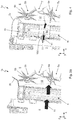
- FIG. 1 shows a bypass flow path of prior art disposed in the vertical direction with respect to the heat exchanger and extending in the horizontal direction
- FIG. 2 shows a bypass flow path disposed in the vertical direction with respect to the heat exchanger and extending in the horizontal direction as well as with a flow guide mechanism at the outlet port of the bypass flow path,
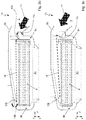
- FIG. 3A shows at least one bypass flow path disposed in a horizontal direction with respect to the heat exchanger and extending in a horizontal direction
- FIG. 3B shows a split bypass flow path according to FIG. 3A , each path in an opened state, disposed in a horizontal direction with respect to the heat exchanger and extending in a horizontal direction,
- FIG. 3C shows a split bypass flow path according to FIG. 3A , each in a closed state, disposed in a horizontal direction with respect to the heat exchanger and extending in a horizontal direction,
- FIG. 3D shows a split bypass flow path according to FIG. 3B with a coupling element for the control of air guide mechanisms of the split bypass flow paths in the opened state, as well as
- FIG. 3E shows a split bypass flow path according to FIG. 3C with a coupling element for the control of air guide mechanisms of the split bypass flow paths in the closed state
- FIG. 4 shows a split heat exchanger with a bypass flow path extending in the horizontal direction between the elements of the heat exchanger.
- FIG. 1 is shown in cross section a climate control device 1 ′ of a climate control system of a motor vehicle, with a housing 2 a with a diffuser 3 as well as with a heat exchanger 4 for conditioning the inflowing air for a passenger compartment, in particular an evaporator 4 of a refrigerant circulation of prior art.
- the climate control device 1 ′ comprises a bypass flow path 9 a , developed in the vertical direction z above the heat exchanger 4 , which extends in a plane spanned by the horizontal directions x, y.
- the heat exchanger 4 is substantially disposed in a plane spanned by the horizontal direction y and the vertical direction z.
- the bypass flow path 9 a is developed at an end side, oriented in the vertical direction z, of the heat exchanger 4 .
- the climate control device 1 ′ comprises a, not shown, fan for taking in the air through the air inlet as well as for conveying the air through the housing 2 a with the diffuser 3 .
- the fan can take in, as needed, fresh air from the surroundings, ambient air from the passenger compartment or a mixture of fresh air and ambient air.
- An air mass flow taken in through the air inlet into housing 2 a and conducted through the diffuser 3 to an evaporator region can, as needed and according to the operating mode of the climate control system, be split into a first air mass subflow flowing through the heat exchanger 4 , operated as evaporator of the refrigerant circulation, and into a second air mass subflow flowing through the bypass flow path 9 a .
- a flow guide mechanism 10 ′ implemented within the bypass flow path 9 a the bypass flow path 9 a can be opened and closed continuously between 0% and 100% such that an air mass flow conveyed in housing 2 a can be split between 0% and 100% into the first air mass subflow or the second air mass subflow.
- the first air mass subflow is conducted across the heat transfer surface of evaporator 4 of the refrigerant circulation.
- the air of the first air mass subflow can be cooled and/or dehumidified.
- the air of the second air mass subflow conducted through the bypass flow path 9 a is not conditioned. After it has flowed through the evaporator 4 or the bypass flow path 9 a , the air mass subflows are to be mixed with one another again.
- the air mass flow can subsequently be split into an air mass subflow flowing through a first flow path 5 a , in particular a warm air path, and an air mass subflow flowing through a second flow path 5 b , in particular a cold air path.
- the air mass flow can herein be conducted in its entirety into one of the flow paths 5 a , 5 b or proportionately into both flow paths 5 a , 5 b.
- the air mass flows conducted through the warm air path 5 a and the cold air path 5 b are controlled with the aid of flow guide mechanisms 6 a , 6 b opening or closing the flow paths 5 a , 5 b , wherein the flow guide mechanisms 6 a , 6 b , developed as temperature dampers, in an end position are each completely closing or opening the warm air path 5 a or the cold air path 5 b and in intermediate positions clear a portion of the flow cross section of the warm air path 5 a and of the cold air path 5 b .
- the flow paths 5 a , 5 b , opening out into a mixing chamber 8 by means of the flow guide mechanisms 6 a , 6 b are closable and openable continuously between 0% and 100% such that the air mass flow conveyed in housing 2 a can be split between 0% and 100% onto the flow paths in proportions between 0% and 100%.
- the flow paths 5 a , 5 b should be enabled to be supplied with air conditioned in evaporator 4 or with air conducted through the bypass flow path 9 a or with an air mass flow of a mixture of the air conditioned in evaporator 4 as well as of the air conducted through the bypass flow path 9 a.
- air outlets not shown, to the windshield, to the footwell and in the dashboard are implemented to open out into the mixing chamber 8 .
- the air mass flow conducted through the warm air path 5 a is heated when flowing across a heat exchanger 7 in particular a heating heat exchanger.
- the heated air mass flow is subsequently directed into the mixing chamber 8 and can be mixed with the air mass flow of the cold air flowing through the cold air path 5 b and also directed into the mixing chamber 8 .
- the second flow path 5 b is consequently developed as a bypass to the first flow path 5 a .
- An air mass flow conducted through the second flow path 5 b does not experience any change of temperature.
- An air mass flow conducted through the first flow path 5 a is conducted in its entirety across the heat transfer surfaces of the heating heat exchanger 7 and is heated.
- the flow guide mechanism 10 ′ for closing and opening the bypass flow path 9 a is disposed in the vertical direction z as well as in particular in the horizontal direction x centrally in the flow cross section of the bypass flow path 9 a and centered with respect to the evaporator 4 . Therefore, the flow guide mechanism 10 ′ as well as its reception in the proximity of the rotational axis is disposed completely within the flow cross section of the bypass flow path 9 a , such that the flow cross section of the bypass flow path 9 a is at least partially blocked, which increases the flow resistance of the air during its flow through the bypass flow path 9 a .
- the air quantity that can be conducted through the bypass flow path 9 a in the direction of flow 11 is thereby strongly affected and reduced.
- the air mass flow flowing out of the bypass flow path 9 a can, moreover, flow in the direction of flow 11 ′ through the second flow path 5 b unhindered and directly into the mixing chamber 8 as well as to the air outlets disposed above the evaporator 4 in the vertical direction z and cannot be guided to the first flow path 5 a , which leads to an undesirable effect on the temperature distribution of the air for the passenger compartment. Since in particular the air outlet to the windshield opens out in said region of the mixing chamber 8 , the nonconditioned air is directly directed to the windshield which can result in the formation of condensation on the windshield.
- the first air mass subflow conducted across the heat transfer surface of evaporator 4 of the refrigerant circulation and cooled and/or dehumidified in the process as well as the second air mass subflow conducted through the bypass flow path 9 a and nonconditioned, are not sufficiently mixed with one another as would be desired.
- FIG. 2 is shown in cross section a climate control device 1 a of a climate control system of a motor vehicle with the housing 2 a with the diffuser 3 as well as the heat exchanger 4 , in particular the evaporator 4 of the refrigerant circulation, for conditioning the inflowing air for the passenger compartment.
- the climate control device 1 a comprises also the bypass flow path 9 a disposed in the vertical direction z above the evaporator 4 , which extends in the plane spanned by the horizontal directions x, y.
- climate control devices 1 a , 1 ′ are identified by identical reference numbers. For the implementation of identical features, reference is made to the explanations of FIG. 1 .
- the flow guide mechanism 10 a for opening and closing the bypass flow path 9 a is disposed, for one, at the outlet port of the bypass flow path 9 a and, for another, in the proximity of the wall of the bypass flow path 9 a such that the flow cross section of the opened bypass flow path 9 a is not decreased by the flow guide mechanism 10 a.
- the flow guide mechanism 10 a implemented as an end-supported air damper, that is with a rotational axis disposed on a first end of the air damper, as well as its reception is disposed in the proximity of the rotational axis outside of the flow cross section of the bypass flow path 9 a such that the flow resistance of the air during its flow through the bypass flow path 9 a as well as also the air quantity that can be conducted through the bypass flow path 9 a are not affected.
- the flow cross section of the opened bypass flow path 9 a and the air quantity that can be conducted through the bypass flow path 9 a are increased and the flow resistance of air during its flow through the bypass flow path 9 a in the direction of flow 11 is as well decreased.
- bypass flow path 9 a With the disposition of the flow guide mechanism 10 a in the second end position, and therewith with the bypass flow path 9 a completely opened, the bypass flow path 9 a is moreover expanded up into a mixing zone 12 such that the air mass flow flowing out of the bypass flow path 9 a in the direction of flow 11 is directed in the vertical direction z downwardly into the mixing zone 12 such that, on the one hand, an unhindered and direct introduction of the air mass flow, conducted and nonconditioned through bypass flow path 9 a , into the mixing chamber 8 as well as a flow to the air outlets, disposed in the vertical direction z above the evaporator 4 , is prevented.
- a second end, developed distally to the first end, of the air damper 10 a projects into the mixing zone 12 .
- the second air mass subflow conducted through the bypass flow path 9 a can be conducted more directly than is the case in the prior art climate control device 1 ′ according to FIG. 1 to the first flow path 5 a with the heating heat exchanger 7 disposed therein
- the first air mass subflow, conducted and cooled and/or dehumidified across the heat transfer surface of evaporator 4 , as well as the second air mass subflow, conducted and non-conditioned through the bypass flow path 9 a , are sufficiently mixed with one another to ensure the desired temperature distribution at the air outlets into the passenger compartment.
- the air mass flow conducted through the bypass flow path 9 a is to be guided directly up to the warm air path 5 a , in particular to the temperature damper 6 a , and through the warm air path 5 a with the heating heat exchanger 7 specifically into the mixing chamber 8 .
- a climate control device 1 b of a climate control system of a motor vehicle is shown in cross section with a housing 2 b with diffuser 3 as well as with the heat exchanger 4 for conditioning the inflowing air for the passenger compartment, in particular the evaporator 4 of the refrigerant circulation.
- the climate control device 1 b comprises at least one bypass flow path, developed next to the heat exchanger 4 in the horizontal direction y, which extends in a plane spanned by the horizontal direction x and the vertical direction z.
- the heat exchanger 4 is in contact with the end sides directed in the vertical direction z on the wall of housing 2 b , wherein between these end sides and the wall no bypass flow path is developed.
- FIG. 3B to 3E show each the climate control device 1 b with the housing 2 b with the diffuser 3 as well as with the heat exchanger 4 , in particular the evaporator 4 , of FIG. 3A in cross section.
- the climate control device 1 b comprises a split bypass flow path 9 b , 9 c extending in a plane developed in the horizontal direction y next to the heat exchanger 4 spanned by the horizontal direction x and the vertical direction z.
- the bypass flow paths 9 b , 9 c are each shown in an opened state and according to FIG. 3C as well as FIG. 3E in a closed state.
- the bypass flow paths 9 b , 9 c are each disposed in the horizontal direction y laterally to the evaporator 4 , in particular on end sides oriented in the horizontal direction y, such that with the bypass flow paths 9 b , 9 c opened, the second air mass subflow conducted through the bypass flow paths 9 b , 9 c is, again split into air mass subflows, conducted through a first bypass flow path 9 b and a second bypass flow path 9 c .
- the bypass flow paths 9 b , 9 c open out into a mixing zone 12 developed, in the direction of flow 11 of the air, after the evaporator 4 .
- the second air mass subflow conducted through the bypass flow paths 9 b , 9 c can be conducted on a direct path to the warm air path.
- the air mass subflows substantially conducted in the horizontal direction x through the bypass flow paths 9 b , 9 c and consequently laterally past the evaporator 4 , can, depending on the operating mode, be mixed with the air mass subflow flowing through evaporator 4 in the direction of flow 11 before the, not shown, temperature dampers of the warm air path with the heating heat exchanger and of the cold air path.
- the air is subsequently supplied to the warm air path and/or the cold air path.
- the bypass flow paths 9 b , 9 c are each openable and closable continuously between 0% and 100% with a flow guide mechanism 10 b , 10 c .
- Each flow guide mechanism 10 b , 10 c is disposed at the inlet port of the bypass flow paths 9 b , 9 c as well as in the proximity of the wall of housing 2 b , in particular of the bypass flow paths 9 b , 9 c , such that the flow cross sections of the opened bypass flow paths 9 b , 9 c are not affected.
- the flow guide mechanisms 10 b , 10 c implemented as end-supported air dampers, in particular each with a rotational axis on a first end of the air damper, as well as their reception in the proximity of the rotational axis, are disposed outside of the flow cross sections of the bypass flow paths 9 b , 9 c such that the flow resistance of the air when flowing through the bypass flow paths 9 b , 9 c as well as also the air quantities, that can be conducted in the direction of flow 11 through the bypass flow paths 9 b , 9 c , remain free of any influence by the flow guide mechanisms 10 b , 10 c.
- the air dampers 10 b of the first bypass flow path 9 b and of the second bypass flow path 9 c are each implemented and disposed such that they, in a first end position in the closed state of the bypass flow paths 9 b , 9 c , according to FIG. 3C , guide the air mass flow conveyed into the housing 2 b as a portion of the wall along the wall of housing 2 b in the direction of the heat exchanger 4 .
- the second end, developed distally to the first end, of the air damper 10 b of the first bypass, flow path 9 b is in contact on a margin region of the heat exchanger 4 .
- the second end of air damper 10 c of the second bypass flow path 9 c developed distally to the first end, is in contact on the wall of housing 2 b such that it extends the wall in the direction of heat exchanger 4 .
- the air damper 10 b In a second end position of air dampers 10 b , 10 c according to FIG. 3B , and thus in the opened state of the first bypass flow path 9 b , the air damper 10 b is disposed in contact on the wall of housing 2 b or integrated within the wall of housing 2 b .
- the air damper 10 c In a second end position, in the opened state of the second bypass flow path 9 c , the air damper 10 c is disposed such that it projects with the second, free end in particular into the diffuser 3 , disposed in the direction of flow 11 of the air after the air inlet, such that a first air mass subflow is guided into the second bypass flow path 9 c and a second air mass subflow to the heat exchanger 4 as well as to the first bypass flow path 9 b .
- bypass flow path 9 c With the air damper 10 c in the open position, consequently an air mass subflow of the air mass flow conducted through the diffuser 3 is branched off and conducted into the bypass flow path 9 c .
- the separation of the second air mass subflow through the heat exchanger 4 and the first bypass flow path 9 b occurs via the flow resistances of the air when flowing through the heat exchanger 4 and of the first bypass flow path 9 b .
- the bypass flow path 9 b is developed such that the proportions of the air mass flows conducted through the bypass flow paths 9 b , 9 c are as much as possible equal.
- the flow guide mechanisms 10 b , 10 c disposed in the horizontal direction y laterally to the evaporator 4 are disposed according to FIG. 3D such that they can be swiveled in opposite directions about a rotational axis in a direction of rotation 13 b , 13 c .
- the flow guide mechanisms 10 b , 10 c are mechanically connected with one another by means of a coupling element 14 for the control of the opening and closing processes of the bypass flow paths 9 b , 9 c.
- the coupling element 14 for example of rodding, is connected with the flow guide mechanisms 10 b , 10 c such that a motion of the coupling elements 14 executed substantially in the horizontal direction y, results in the rotation in particular continuously of the flow guide mechanisms 10 b , 10 c in the oppositely directed directions of rotation 13 b , 13 C between the end positions.
- FIG. 4 is depicted in cross section a climate control device 1 c of a climate control system of a motor vehicle with a housing 2 c with the diffuser 3 as well as with a heat exchanger 4 c in particular with an evaporator 4 c of the refrigerant circulation for conditioning the inflowing air for a passenger compartment.
- the climate control device 1 c comprises a split heat exchanger 4 c with a bypass flow path 9 d extending in a plane spanned by the horizontal directions x, y between the elements of the heat exchanger 4 c.
- the essential difference between the climate control device 1 c according to FIG. 4 and the climate control device 1 a of FIG. 2 and the climate control device 1 b of FIG. 3A is evident in the implementation and the disposition of flow path 9 d .
- the heat exchanger 4 c is in contact with the end sides oriented in the vertical direction z on the wall of housing 2 c , wherein between the end sides and the wall no bypass flow path is developed.
- the heat exchanger 4 c is implemented of at least one first element, in the vertical direction y the upper element, as well as of a second, in the vertical direction y, the lower element.
- the elements of the heat exchange 4 c are spaced apart in the vertical direction y such that between the elements a throughflow, in particular the bypass flow path 9 d , remains for the air taken into the housing 2 c .
- the elements of the heat exchanger 4 c can have the same dimensions or be dimensioned differently.
- the air mass subflows, conducted in the direction of flow 11 and thus substantially in the horizontal direction x, through the elements of evaporator 4 c as well as through the bypass flow path 9 d , are, depending on the operating mode, mixed in the mixing zone 12 developed before the temperature damper 6 a of the warm air path 5 a with the heating heat exchanger and the temperature damper 6 b of the cold air path 5 b .
- the mixed air is subsequently supplied to the warm air path 5 a and/or to the cold air path 5 b .
- the second air mass subflow conducted through the bypass flow path 9 d can also be guided directly to the warm air path 5 a with the heating heat exchanger 7 disposed therein.
- the first air mass subflow, conducted across the heat transfer surfaces of evaporator 4 c of the refrigerant circulation and cooled and/or dehumidified, as well as the second air mass subflow, conducted through the bypass flow path 9 d and not conditioned, are sufficiently mixed with one another to ensure a desired temperature distribution at the air outlets into the passenger compartment.
- the flow path 9 d implemented to open out into the mixing zone 12 such that the air mass flow guided through the flow path 9 d and past the evaporator 4 c can also be guided directly to the temperature damper 6 a of the warm air path 5 a in order to decrease further the effect of the air mass flow, conducted through the bypass flow path 9 d , on the temperature distribution of the inflowing air to be introduced through the air outlets into the passenger compartment.
- the bypass flow path 9 d is openable and closable continuously between 0% and 100% with a flow guide mechanism 10 d .
- the flow guide mechanism 10 d developed as air damper with a central rotational axis, is herein disposed at the inlet port of the bypass flow path 9 d within the open flow cross section. According to alternative, not shown, embodiments, the flow guide mechanism is disposed at the outlet port of the bypass flow path 9 d into the mixing zone 12 or in the horizontal direction x centered with respect to evaporator 4 c .
- the flow guide mechanism can, furthermore, also be developed as an end-supported air damper, which means with a rotational axis disposed on a first end of the air damper, in order to be disposed in the opened state outside of the flow cross section of the bypass flow path 9 d.
- a maximal air quantity can be guided around the evaporator 4 , 4 c , whereby the air quantity depends on the available cross-sectional space, which means on the width and height of the flow cross sections of the bypass flow paths 9 d , 9 c as well as on the flow cross section of the flow path 9 d .
- the pressure loss of the bypass flow path is in each case minimal.
- the second air mass subflow conducted through the bypass flow paths 9 b , 9 c , 9 d and the first air mass subflow conducted through evaporator 4 , 4 c , are again mixed with one another such that the characteristic of the temperature distribution at the air outlets of the climate control device 1 b , 1 c is positively affected or not affected at all, such that a desired temperature distribution is achieved.
Landscapes
- Physics & Mathematics (AREA)
- Thermal Sciences (AREA)
- Engineering & Computer Science (AREA)
- Mechanical Engineering (AREA)
- Air-Conditioning For Vehicles (AREA)
Abstract
Description
-
- selective air routing, in particular through the bypass flow path, results in minimal influence of the bypass flow path on the temperature distribution of the air to be supplied to the passenger compartment or on control curves of the air temperature,
- maximal air quantity conductible through the bypass flow path at given low installation space,
- enhancement of the efficiency of the operation of the climate control system with energy-efficient temperature regulation, also through energy savings due to the lower necessary cooling power,
- humidity control of the air in the passenger compartment by means of outside air conducted through bypass flow path, which allows introducing additional air humidity into the passenger compartment—additional humidity input can at least be utilized within a limited frame to control the air humidity in the passenger compartment thereby that more humid outside air is mixed to the dehumidified air after the evaporator such that the relative air humidity in the passenger compartment can be adjusted to a comfortable level—therewith
- requirements with respect to temperature distribution and air temperature control, temperature as well as air quantity can be met,
- minimal installation space requirement as well as
- maximal level of comfort for the occupants of the passenger compartment.
- 1 a, 1 b, 1 c, 1′ Climate control device
- 2 a, 2 b, 2 c Housing
- 3 Diffuser
- 4, 4 c Heat exchanger, evaporator refrigerant circulation
- 5 a First flow path, warm air path
- 5 b Second flow path, cold air path
- 6 a First flow guide mechanism, temperature damper
warm air path 5 a - 6 b Second flow guide mechanism, temperature damper
cold air path 5 b - 7 Heat exchanger, heating heat exchanger
- 8 Mixing chamber
- 9 a, 9 d Bypass flow path evaporator 4
- 9 b First bypass flow path evaporator 4
- 9 c Second bypass flow path evaporator 4
- 10 a, 10 d, 10′ Flow guide mechanism, air damper bypass flow path
- 10 b Flow guide mechanism, air damper bypass flow path
- 10 c Flow guide mechanism, air damper bypass flow path
- 11, 11′ Direction of flow of air
- 12 Mixing zone
- 13 b Direction of rotation third
flow guide mechanism 10 b - 13 c Direction of rotation fourth
flow guide mechanism 10 c - 14 Coupling element flow
guide mechanisms - x, y Horizontal direction
- z Vertical direction
Claims (17)
Applications Claiming Priority (2)
| Application Number | Priority Date | Filing Date | Title |
|---|---|---|---|
| DE102018106321.0 | 2018-03-19 | ||
| DE102018106321.0A DE102018106321B4 (en) | 2018-03-19 | 2018-03-19 | Air conditioner for a motor vehicle |
Publications (2)
| Publication Number | Publication Date |
|---|---|
| US20190283523A1 US20190283523A1 (en) | 2019-09-19 |
| US11040592B2 true US11040592B2 (en) | 2021-06-22 |
Family
ID=67774362
Family Applications (1)
| Application Number | Title | Priority Date | Filing Date |
|---|---|---|---|
| US16/282,603 Active 2039-04-07 US11040592B2 (en) | 2018-03-19 | 2019-02-22 | Climate control device for a motor vehicle |
Country Status (4)
| Country | Link |
|---|---|
| US (1) | US11040592B2 (en) |
| KR (1) | KR102210270B1 (en) |
| CN (2) | CN110281729B (en) |
| DE (1) | DE102018106321B4 (en) |
Families Citing this family (2)
| Publication number | Priority date | Publication date | Assignee | Title |
|---|---|---|---|---|
| CZ310605B6 (en) * | 2020-05-15 | 2026-01-21 | ŠKODA AUTO a.s. | An air distribution equipment |
| CN112644245B (en) * | 2020-12-18 | 2022-09-30 | 艾泰斯热系统研发(上海)有限公司 | Air-conditioning box structure |
Citations (22)
| Publication number | Priority date | Publication date | Assignee | Title |
|---|---|---|---|---|
| US4453591A (en) * | 1980-04-30 | 1984-06-12 | Suddeutsche Kuhlerfabrik Julius Fr. Behr Gmbh & Co. Kg | Air-conditioning apparatus for motor vehicles |
| US5299431A (en) * | 1991-04-26 | 1994-04-05 | Nippondenso Co., Ltd. | Automotive air conditioner having condenser and evaporator provided within air duct |
| US5738579A (en) * | 1995-12-22 | 1998-04-14 | Valeo Climatisation | Heating ventilating and/or air conditioning apparatus, especially for motor vehicles |
| US5975191A (en) * | 1996-09-25 | 1999-11-02 | Calsonic Corporation | Vehicle air conditioner |
| US6311763B1 (en) * | 1999-04-28 | 2001-11-06 | Denso Corporation | Vehicle air conditioner |
| US6330909B1 (en) * | 1998-10-23 | 2001-12-18 | Denso Corporation | Vehicle air conditioning system |
| US6640570B2 (en) * | 2001-09-27 | 2003-11-04 | Denso Corporation | Vehicle air conditioner with heat pump refrigerant cycle |
| US6688120B2 (en) * | 2001-01-23 | 2004-02-10 | Denso Corporation | Vehicle air conditioner with cold storage and cold release |
| EP1510375A1 (en) | 2003-08-25 | 2005-03-02 | Behr France S.A.R.L. | Air conditioning installation and method for operating one such installation |
| JP2006027377A (en) | 2004-07-14 | 2006-02-02 | Denso Corp | Air-conditioner for vehicle |
| JP2007182206A (en) | 2005-12-06 | 2007-07-19 | Denso Corp | Heat exchanger for heating and air conditioner |
| US20080061159A1 (en) * | 2006-09-11 | 2008-03-13 | Denso Corporation | Electrical heater and vehicle air conditioner |
| JP2011111094A (en) | 2009-11-30 | 2011-06-09 | Denso Corp | Air conditioner for vehicle |
| DE102010029495A1 (en) | 2010-05-31 | 2011-12-01 | Behr Gmbh & Co. Kg | Temperature control device and method for producing a tempered air flow |
| DE102010031444A1 (en) | 2010-07-16 | 2012-01-19 | Visteon Global Technologies, Inc. | Heat exchanger arrangement for being arranged within air-duct of air conditioner of motor car, has bypass including deflection regions and separation edges to maximize thermal output transferred between surface and air-mass flow |
| DE102014209452A1 (en) | 2013-05-21 | 2014-11-27 | Behr Gmbh & Co. Kg | Air conditioning with bypass device |
| US20150158365A1 (en) * | 2012-02-06 | 2015-06-11 | Denso Corporation | Vehicular air conditioner |
| US20150174985A1 (en) * | 2013-12-20 | 2015-06-25 | MAHLE Behr GmbH & Co. KG | Air-conditioning system, in particular for a motor vehicle |
| US9242526B2 (en) * | 2012-08-31 | 2016-01-26 | Hanon Systems | Air conditioning system for a motorized vehicle |
| US9346337B2 (en) * | 2011-02-24 | 2016-05-24 | Panasonic Intellectual Property Management Co., Ltd. | Air conditioning device for vehicle |
| US20160272037A1 (en) * | 2012-11-13 | 2016-09-22 | Valeo Klimasysteme Gmbh | Vehicle air conditioner |
| US20170087956A1 (en) * | 2015-09-28 | 2017-03-30 | Hanon Systems | HV iCOOL LIGHT HVAC |
Family Cites Families (10)
| Publication number | Priority date | Publication date | Assignee | Title |
|---|---|---|---|---|
| FR2727359B1 (en) * | 1994-11-29 | 1997-01-10 | Valeo Thermique Habitacle | HOUSING FOR THE HOUSING OF A HEAT EXCHANGER IN A HEATING AND / OR AIR CONDITIONING SYSTEM OF A MOTOR VEHICLE |
| JP4075168B2 (en) * | 1998-12-04 | 2008-04-16 | 株式会社デンソー | Air conditioner for vehicles |
| JP4452849B2 (en) * | 2002-07-29 | 2010-04-21 | ベール ゲーエムベーハー ウント コー カーゲー | Air conditioning housing |
| WO2009075255A1 (en) * | 2007-12-10 | 2009-06-18 | Calsonic Kansei Corporation | Air conditioner for automobile |
| JP5761952B2 (en) * | 2010-10-05 | 2015-08-12 | 三菱重工業株式会社 | Air conditioner for vehicles |
| FR2975344B1 (en) * | 2011-05-20 | 2016-04-29 | Valeo Systemes Thermiques | APPARATUS FOR HEATING, VENTILATION AND / OR AIR CONDITIONING COMPRISING AN AIR CIRCULATION CHANNEL CONVERTING A HEAT EXCHANGER |
| CN103826889B (en) * | 2011-09-28 | 2016-04-20 | 汉拿伟世通空调有限公司 | Car air-conditioner equipment |
| BR112016029174A2 (en) * | 2014-06-30 | 2017-08-22 | Valeo Systemes Thermiques | method for operating a climate control device for a passenger compartment of a motor vehicle |
| JP6078575B2 (en) * | 2015-03-30 | 2017-02-08 | 富士重工業株式会社 | Air conditioner device for vehicles |
| DE102017116191B4 (en) * | 2016-07-27 | 2023-12-21 | Hanon Systems | Air conditioning system for multi-zone air conditioning of a vehicle interior |
-
2018
- 2018-03-19 DE DE102018106321.0A patent/DE102018106321B4/en active Active
-
2019
- 2019-02-22 US US16/282,603 patent/US11040592B2/en active Active
- 2019-03-12 KR KR1020190028323A patent/KR102210270B1/en active Active
- 2019-03-18 CN CN201910203579.4A patent/CN110281729B/en active Active
- 2019-03-18 CN CN202211444424.8A patent/CN115782511B/en active Active
Patent Citations (24)
| Publication number | Priority date | Publication date | Assignee | Title |
|---|---|---|---|---|
| US4453591A (en) * | 1980-04-30 | 1984-06-12 | Suddeutsche Kuhlerfabrik Julius Fr. Behr Gmbh & Co. Kg | Air-conditioning apparatus for motor vehicles |
| US5299431A (en) * | 1991-04-26 | 1994-04-05 | Nippondenso Co., Ltd. | Automotive air conditioner having condenser and evaporator provided within air duct |
| US5738579A (en) * | 1995-12-22 | 1998-04-14 | Valeo Climatisation | Heating ventilating and/or air conditioning apparatus, especially for motor vehicles |
| US5975191A (en) * | 1996-09-25 | 1999-11-02 | Calsonic Corporation | Vehicle air conditioner |
| US6330909B1 (en) * | 1998-10-23 | 2001-12-18 | Denso Corporation | Vehicle air conditioning system |
| US6311763B1 (en) * | 1999-04-28 | 2001-11-06 | Denso Corporation | Vehicle air conditioner |
| US6688120B2 (en) * | 2001-01-23 | 2004-02-10 | Denso Corporation | Vehicle air conditioner with cold storage and cold release |
| US6640570B2 (en) * | 2001-09-27 | 2003-11-04 | Denso Corporation | Vehicle air conditioner with heat pump refrigerant cycle |
| EP1510375A1 (en) | 2003-08-25 | 2005-03-02 | Behr France S.A.R.L. | Air conditioning installation and method for operating one such installation |
| JP2006027377A (en) | 2004-07-14 | 2006-02-02 | Denso Corp | Air-conditioner for vehicle |
| JP2007182206A (en) | 2005-12-06 | 2007-07-19 | Denso Corp | Heat exchanger for heating and air conditioner |
| US20080061159A1 (en) * | 2006-09-11 | 2008-03-13 | Denso Corporation | Electrical heater and vehicle air conditioner |
| JP2011111094A (en) | 2009-11-30 | 2011-06-09 | Denso Corp | Air conditioner for vehicle |
| DE102010029495A1 (en) | 2010-05-31 | 2011-12-01 | Behr Gmbh & Co. Kg | Temperature control device and method for producing a tempered air flow |
| US20130098595A1 (en) | 2010-05-31 | 2013-04-25 | Behr Gmbh & Co. Kg | Temperature control device and method for generating a temperature-controlled air flow |
| DE102010031444A1 (en) | 2010-07-16 | 2012-01-19 | Visteon Global Technologies, Inc. | Heat exchanger arrangement for being arranged within air-duct of air conditioner of motor car, has bypass including deflection regions and separation edges to maximize thermal output transferred between surface and air-mass flow |
| US9346337B2 (en) * | 2011-02-24 | 2016-05-24 | Panasonic Intellectual Property Management Co., Ltd. | Air conditioning device for vehicle |
| US20150158365A1 (en) * | 2012-02-06 | 2015-06-11 | Denso Corporation | Vehicular air conditioner |
| US9242526B2 (en) * | 2012-08-31 | 2016-01-26 | Hanon Systems | Air conditioning system for a motorized vehicle |
| US20160272037A1 (en) * | 2012-11-13 | 2016-09-22 | Valeo Klimasysteme Gmbh | Vehicle air conditioner |
| DE102014209452A1 (en) | 2013-05-21 | 2014-11-27 | Behr Gmbh & Co. Kg | Air conditioning with bypass device |
| US20150174985A1 (en) * | 2013-12-20 | 2015-06-25 | MAHLE Behr GmbH & Co. KG | Air-conditioning system, in particular for a motor vehicle |
| US20170087956A1 (en) * | 2015-09-28 | 2017-03-30 | Hanon Systems | HV iCOOL LIGHT HVAC |
| CN106965640A (en) * | 2015-09-28 | 2017-07-21 | 翰昂汽车零部件有限公司 | Air-conditioning system and the air that air mass flow is oriented in air-conditioning system guide equipment |
Non-Patent Citations (1)
| Title |
|---|
| JP2006027377 A—English machine translation.pdf (Year: 2006). * |
Also Published As
| Publication number | Publication date |
|---|---|
| CN110281729B (en) | 2023-04-11 |
| DE102018106321B4 (en) | 2023-06-01 |
| CN110281729A (en) | 2019-09-27 |
| DE102018106321A1 (en) | 2019-09-19 |
| CN115782511A (en) | 2023-03-14 |
| KR102210270B1 (en) | 2021-02-02 |
| CN115782511B (en) | 2024-06-14 |
| US20190283523A1 (en) | 2019-09-19 |
| KR20190110031A (en) | 2019-09-27 |
Similar Documents
| Publication | Publication Date | Title |
|---|---|---|
| KR101952118B1 (en) | Air-conditioning system for conditioning the air of a passenger compartment of a motor vehicle | |
| US10363792B2 (en) | Air-conditioning system for cooling and drying air in passenger compartment of vehicle | |
| US20210300155A1 (en) | Vehicle air conditioning apparatus | |
| US9446654B2 (en) | Vehicle air conditioner | |
| KR20140116157A (en) | Vehicle air conditioning device | |
| US11554630B2 (en) | Vehicular air conditioner having heating heat exchanger disposed downstream of blower fan | |
| US10350962B2 (en) | Assembly for air distribution for an air conditioning system of an automobile | |
| KR102056123B1 (en) | Air distribution assembly for an air-conditioning system of a motor vehicle | |
| CN110678338B (en) | Air conditioner for vehicle | |
| KR102536570B1 (en) | Air conditioner for vehicle | |
| US11040592B2 (en) | Climate control device for a motor vehicle | |
| KR101648124B1 (en) | Air conditioning system for vehicles | |
| KR20110090478A (en) | Car air conditioner | |
| US12103358B2 (en) | Vehicle air conditioner | |
| KR102136606B1 (en) | Air-conditioning system for a motor vehicle | |
| KR102218419B1 (en) | Air-conditioning system for a motor vehicle | |
| KR20190032207A (en) | Heater/air conditioning for a motor vehicle | |
| KR101425880B1 (en) | Air conditioner for vehicle | |
| KR20170085163A (en) | Air conditioner for vehicle | |
| JP2017177833A (en) | Air-conditioner for vehicle | |
| KR20190032206A (en) | Air conditioner for a motor vehicle | |
| KR20180131405A (en) | Air-conditioning system for a motor vehicle | |
| KR20050112279A (en) | Air conditioning system for a car | |
| KR20190038306A (en) | Air-conditioning system for a motor vehicle | |
| KR20190013598A (en) | Air conditioner for a motor vehicle and method for operating the air conditioner |
Legal Events
| Date | Code | Title | Description |
|---|---|---|---|
| FEPP | Fee payment procedure |
Free format text: ENTITY STATUS SET TO UNDISCOUNTED (ORIGINAL EVENT CODE: BIG.); ENTITY STATUS OF PATENT OWNER: LARGE ENTITY |
|
| AS | Assignment |
Owner name: HANON SYSTEMS, KOREA, REPUBLIC OF Free format text: ASSIGNMENT OF ASSIGNORS INTEREST;ASSIGNORS:CAPELLMANN, CHRISTOPH;DUKA, EVZI;EHLERS, THOMAS;SIGNING DATES FROM 20190315 TO 20190319;REEL/FRAME:048763/0353 |
|
| STPP | Information on status: patent application and granting procedure in general |
Free format text: DOCKETED NEW CASE - READY FOR EXAMINATION |
|
| STPP | Information on status: patent application and granting procedure in general |
Free format text: NON FINAL ACTION MAILED |
|
| STPP | Information on status: patent application and granting procedure in general |
Free format text: RESPONSE AFTER FINAL ACTION FORWARDED TO EXAMINER |
|
| STPP | Information on status: patent application and granting procedure in general |
Free format text: NOTICE OF ALLOWANCE MAILED -- APPLICATION RECEIVED IN OFFICE OF PUBLICATIONS |
|
| STPP | Information on status: patent application and granting procedure in general |
Free format text: PUBLICATIONS -- ISSUE FEE PAYMENT RECEIVED |
|
| STPP | Information on status: patent application and granting procedure in general |
Free format text: PUBLICATIONS -- ISSUE FEE PAYMENT VERIFIED |
|
| STCF | Information on status: patent grant |
Free format text: PATENTED CASE |
|
| MAFP | Maintenance fee payment |
Free format text: PAYMENT OF MAINTENANCE FEE, 4TH YEAR, LARGE ENTITY (ORIGINAL EVENT CODE: M1551); ENTITY STATUS OF PATENT OWNER: LARGE ENTITY Year of fee payment: 4 |