US11033403B2 - Expandable implant assembly - Google Patents
Expandable implant assembly Download PDFInfo
- Publication number
- US11033403B2 US11033403B2 US16/438,076 US201916438076A US11033403B2 US 11033403 B2 US11033403 B2 US 11033403B2 US 201916438076 A US201916438076 A US 201916438076A US 11033403 B2 US11033403 B2 US 11033403B2
- Authority
- US
- United States
- Prior art keywords
- control
- implant
- base member
- expandable implant
- adjustable
- Prior art date
- Legal status (The legal status is an assumption and is not a legal conclusion. Google has not performed a legal analysis and makes no representation as to the accuracy of the status listed.)
- Active, expires
Links
Images


Classifications
-
- A—HUMAN NECESSITIES
- A61—MEDICAL OR VETERINARY SCIENCE; HYGIENE
- A61F—FILTERS IMPLANTABLE INTO BLOOD VESSELS; PROSTHESES; DEVICES PROVIDING PATENCY TO, OR PREVENTING COLLAPSING OF, TUBULAR STRUCTURES OF THE BODY, e.g. STENTS; ORTHOPAEDIC, NURSING OR CONTRACEPTIVE DEVICES; FOMENTATION; TREATMENT OR PROTECTION OF EYES OR EARS; BANDAGES, DRESSINGS OR ABSORBENT PADS; FIRST-AID KITS
- A61F2/00—Filters implantable into blood vessels; Prostheses, i.e. artificial substitutes or replacements for parts of the body; Appliances for connecting them with the body; Devices providing patency to, or preventing collapsing of, tubular structures of the body, e.g. stents
- A61F2/02—Prostheses implantable into the body
- A61F2/30—Joints
- A61F2/44—Joints for the spine, e.g. vertebrae, spinal discs
- A61F2/4455—Joints for the spine, e.g. vertebrae, spinal discs for the fusion of spinal bodies, e.g. intervertebral fusion of adjacent spinal bodies, e.g. fusion cages
- A61F2/447—Joints for the spine, e.g. vertebrae, spinal discs for the fusion of spinal bodies, e.g. intervertebral fusion of adjacent spinal bodies, e.g. fusion cages substantially parallelepipedal, e.g. having a rectangular or trapezoidal cross-section
-
- A—HUMAN NECESSITIES
- A61—MEDICAL OR VETERINARY SCIENCE; HYGIENE
- A61F—FILTERS IMPLANTABLE INTO BLOOD VESSELS; PROSTHESES; DEVICES PROVIDING PATENCY TO, OR PREVENTING COLLAPSING OF, TUBULAR STRUCTURES OF THE BODY, e.g. STENTS; ORTHOPAEDIC, NURSING OR CONTRACEPTIVE DEVICES; FOMENTATION; TREATMENT OR PROTECTION OF EYES OR EARS; BANDAGES, DRESSINGS OR ABSORBENT PADS; FIRST-AID KITS
- A61F2/00—Filters implantable into blood vessels; Prostheses, i.e. artificial substitutes or replacements for parts of the body; Appliances for connecting them with the body; Devices providing patency to, or preventing collapsing of, tubular structures of the body, e.g. stents
- A61F2/02—Prostheses implantable into the body
- A61F2/30—Joints
- A61F2002/30001—Additional features of subject-matter classified in A61F2/28, A61F2/30 and subgroups thereof
- A61F2002/30316—The prosthesis having different structural features at different locations within the same prosthesis; Connections between prosthetic parts; Special structural features of bone or joint prostheses not otherwise provided for
- A61F2002/30329—Connections or couplings between prosthetic parts, e.g. between modular parts; Connecting elements
-
- A—HUMAN NECESSITIES
- A61—MEDICAL OR VETERINARY SCIENCE; HYGIENE
- A61F—FILTERS IMPLANTABLE INTO BLOOD VESSELS; PROSTHESES; DEVICES PROVIDING PATENCY TO, OR PREVENTING COLLAPSING OF, TUBULAR STRUCTURES OF THE BODY, e.g. STENTS; ORTHOPAEDIC, NURSING OR CONTRACEPTIVE DEVICES; FOMENTATION; TREATMENT OR PROTECTION OF EYES OR EARS; BANDAGES, DRESSINGS OR ABSORBENT PADS; FIRST-AID KITS
- A61F2/00—Filters implantable into blood vessels; Prostheses, i.e. artificial substitutes or replacements for parts of the body; Appliances for connecting them with the body; Devices providing patency to, or preventing collapsing of, tubular structures of the body, e.g. stents
- A61F2/02—Prostheses implantable into the body
- A61F2/30—Joints
- A61F2002/30001—Additional features of subject-matter classified in A61F2/28, A61F2/30 and subgroups thereof
- A61F2002/30316—The prosthesis having different structural features at different locations within the same prosthesis; Connections between prosthetic parts; Special structural features of bone or joint prostheses not otherwise provided for
- A61F2002/30535—Special structural features of bone or joint prostheses not otherwise provided for
- A61F2002/30537—Special structural features of bone or joint prostheses not otherwise provided for adjustable
- A61F2002/30538—Special structural features of bone or joint prostheses not otherwise provided for adjustable for adjusting angular orientation
-
- A—HUMAN NECESSITIES
- A61—MEDICAL OR VETERINARY SCIENCE; HYGIENE
- A61F—FILTERS IMPLANTABLE INTO BLOOD VESSELS; PROSTHESES; DEVICES PROVIDING PATENCY TO, OR PREVENTING COLLAPSING OF, TUBULAR STRUCTURES OF THE BODY, e.g. STENTS; ORTHOPAEDIC, NURSING OR CONTRACEPTIVE DEVICES; FOMENTATION; TREATMENT OR PROTECTION OF EYES OR EARS; BANDAGES, DRESSINGS OR ABSORBENT PADS; FIRST-AID KITS
- A61F2/00—Filters implantable into blood vessels; Prostheses, i.e. artificial substitutes or replacements for parts of the body; Appliances for connecting them with the body; Devices providing patency to, or preventing collapsing of, tubular structures of the body, e.g. stents
- A61F2/02—Prostheses implantable into the body
- A61F2/30—Joints
- A61F2002/30001—Additional features of subject-matter classified in A61F2/28, A61F2/30 and subgroups thereof
- A61F2002/30316—The prosthesis having different structural features at different locations within the same prosthesis; Connections between prosthetic parts; Special structural features of bone or joint prostheses not otherwise provided for
- A61F2002/30535—Special structural features of bone or joint prostheses not otherwise provided for
- A61F2002/30537—Special structural features of bone or joint prostheses not otherwise provided for adjustable
- A61F2002/30556—Special structural features of bone or joint prostheses not otherwise provided for adjustable for adjusting thickness
-
- A—HUMAN NECESSITIES
- A61—MEDICAL OR VETERINARY SCIENCE; HYGIENE
- A61F—FILTERS IMPLANTABLE INTO BLOOD VESSELS; PROSTHESES; DEVICES PROVIDING PATENCY TO, OR PREVENTING COLLAPSING OF, TUBULAR STRUCTURES OF THE BODY, e.g. STENTS; ORTHOPAEDIC, NURSING OR CONTRACEPTIVE DEVICES; FOMENTATION; TREATMENT OR PROTECTION OF EYES OR EARS; BANDAGES, DRESSINGS OR ABSORBENT PADS; FIRST-AID KITS
- A61F2/00—Filters implantable into blood vessels; Prostheses, i.e. artificial substitutes or replacements for parts of the body; Appliances for connecting them with the body; Devices providing patency to, or preventing collapsing of, tubular structures of the body, e.g. stents
- A61F2/02—Prostheses implantable into the body
- A61F2/30—Joints
- A61F2002/30001—Additional features of subject-matter classified in A61F2/28, A61F2/30 and subgroups thereof
- A61F2002/30316—The prosthesis having different structural features at different locations within the same prosthesis; Connections between prosthetic parts; Special structural features of bone or joint prostheses not otherwise provided for
- A61F2002/30535—Special structural features of bone or joint prostheses not otherwise provided for
- A61F2002/30579—Special structural features of bone or joint prostheses not otherwise provided for with mechanically expandable devices, e.g. fixation devices
-
- A—HUMAN NECESSITIES
- A61—MEDICAL OR VETERINARY SCIENCE; HYGIENE
- A61F—FILTERS IMPLANTABLE INTO BLOOD VESSELS; PROSTHESES; DEVICES PROVIDING PATENCY TO, OR PREVENTING COLLAPSING OF, TUBULAR STRUCTURES OF THE BODY, e.g. STENTS; ORTHOPAEDIC, NURSING OR CONTRACEPTIVE DEVICES; FOMENTATION; TREATMENT OR PROTECTION OF EYES OR EARS; BANDAGES, DRESSINGS OR ABSORBENT PADS; FIRST-AID KITS
- A61F2/00—Filters implantable into blood vessels; Prostheses, i.e. artificial substitutes or replacements for parts of the body; Appliances for connecting them with the body; Devices providing patency to, or preventing collapsing of, tubular structures of the body, e.g. stents
- A61F2/02—Prostheses implantable into the body
- A61F2/30—Joints
- A61F2002/30001—Additional features of subject-matter classified in A61F2/28, A61F2/30 and subgroups thereof
- A61F2002/30316—The prosthesis having different structural features at different locations within the same prosthesis; Connections between prosthetic parts; Special structural features of bone or joint prostheses not otherwise provided for
- A61F2002/30535—Special structural features of bone or joint prostheses not otherwise provided for
- A61F2002/30593—Special structural features of bone or joint prostheses not otherwise provided for hollow
-
- A—HUMAN NECESSITIES
- A61—MEDICAL OR VETERINARY SCIENCE; HYGIENE
- A61F—FILTERS IMPLANTABLE INTO BLOOD VESSELS; PROSTHESES; DEVICES PROVIDING PATENCY TO, OR PREVENTING COLLAPSING OF, TUBULAR STRUCTURES OF THE BODY, e.g. STENTS; ORTHOPAEDIC, NURSING OR CONTRACEPTIVE DEVICES; FOMENTATION; TREATMENT OR PROTECTION OF EYES OR EARS; BANDAGES, DRESSINGS OR ABSORBENT PADS; FIRST-AID KITS
- A61F2/00—Filters implantable into blood vessels; Prostheses, i.e. artificial substitutes or replacements for parts of the body; Appliances for connecting them with the body; Devices providing patency to, or preventing collapsing of, tubular structures of the body, e.g. stents
- A61F2/02—Prostheses implantable into the body
- A61F2/30—Joints
- A61F2/30767—Special external or bone-contacting surface, e.g. coating for improving bone ingrowth
- A61F2/30771—Special external or bone-contacting surface, e.g. coating for improving bone ingrowth applied in original prostheses, e.g. holes or grooves
- A61F2002/30904—Special external or bone-contacting surface, e.g. coating for improving bone ingrowth applied in original prostheses, e.g. holes or grooves serrated profile, i.e. saw-toothed
-
- A—HUMAN NECESSITIES
- A61—MEDICAL OR VETERINARY SCIENCE; HYGIENE
- A61F—FILTERS IMPLANTABLE INTO BLOOD VESSELS; PROSTHESES; DEVICES PROVIDING PATENCY TO, OR PREVENTING COLLAPSING OF, TUBULAR STRUCTURES OF THE BODY, e.g. STENTS; ORTHOPAEDIC, NURSING OR CONTRACEPTIVE DEVICES; FOMENTATION; TREATMENT OR PROTECTION OF EYES OR EARS; BANDAGES, DRESSINGS OR ABSORBENT PADS; FIRST-AID KITS
- A61F2/00—Filters implantable into blood vessels; Prostheses, i.e. artificial substitutes or replacements for parts of the body; Appliances for connecting them with the body; Devices providing patency to, or preventing collapsing of, tubular structures of the body, e.g. stents
- A61F2/02—Prostheses implantable into the body
- A61F2/30—Joints
- A61F2/44—Joints for the spine, e.g. vertebrae, spinal discs
- A61F2/442—Intervertebral or spinal discs, e.g. resilient
- A61F2/4425—Intervertebral or spinal discs, e.g. resilient made of articulated components
- A61F2002/443—Intervertebral or spinal discs, e.g. resilient made of articulated components having two transversal endplates and at least one intermediate component
Definitions
- the present disclosure relates to expandable implants and devices, including spinal interbody and intravertebral body devices, and vertebral interbody and intravertebral devices that are expandable after spinal placement thereof.
- Fusion cages as well as other types of implants, bodies and/or devices, are frequently utilized in spinal surgery inside a vertebra (intravertebral) and/or between vertebrae of a patient (interbody), or adjacent other bone bodies.
- interbody devices one or more such spinal bodies are placed between vertebrae to provide support and promote fusion between adjacent vertebrae where such is necessary due to disease, injury, general deterioration or congenital problem.
- intravertebral devices one or more spinal bodies are placed within a vertebra.
- Spinal devices such as fusion cages and/or the like, are inserted into a spinal space either anteriorly, posteriorly, laterally or posteriolaterally.
- a problem with most spinal interbody and intravertebral devices is that they are static in size and difficult to position. This poses various problems with their use and/or implantation. Particularly, static sized spinal devices are fairly large in order to properly bridge the gap between adjacent vertebrae. This large size does not lend itself to microsurgery, arthroscopic surgery or the like. Furthermore, spinal devices that are difficult to position require more invasive surgery techniques, and longer surgery time to implant. This complicated positioning does not lend itself to minimally invasive surgery or even outpatient procedures.
- Expandable interbody devices allow the device to be initially smaller than traditional non-expandable (static) interbody devices such that expandable interbody devices may be more easily inserted or implanted into the vertebral space.
- expandable devices allow the surgeon to set the amount of expansion necessary for the particular patient rather than the static device dictating the spacing.
- expandable devices can include attachment points for manipulation tools. Expandable devices integrated with a manipulation tool allows the surgeon to more easily position and expand the implant rather than using several bulkier tools.
- an expandable implant including a base member including a top surface, a first end, and a second end, and defining a central cavity positioned between the first end and the second end.
- the expandable implant further including an adjustable member including a top surface and at least one control channel, wherein the adjustable member is adjustably coupled to the base member and movable between a first, collapsed position, and a second, expanded position, a control shaft received by the base member, wherein manipulation of the control shaft causes relative movement of the adjustable member relative to the base member, and at least one control member coupled to the control shaft and received by the control channel, wherein manipulation of the control shaft causes the control member to translate along the control channel.
- the at least one control channel including a first control channel and a second control channel
- the at least one control member includes a first control member received in the first control channel and a second control member received in the second control channel.
- the first control channel and the second control channel extend in non-parallel directions.
- the first control member and the second control member are at least partially rectangular and include a flat portion configured to engage a corresponding flat portion on the adjustable member to prevent rotation of the first control member within the first control channel and the second control member within the second control channel.
- manipulation of the control shaft includes rotation, and wherein rotation of the control shaft causes the first and second control members to translate in opposite directions along the control shaft.
- a top surface of the adjustable member and a bottom surface of the base member define an implant height of the expandable implant and are configured to engage adjacent portions of bone.
- manipulation of the control member changes a height of the implant.
- an expandable implant including a base member including a central cavity positioned between a first end and a second end of the base member, an adjustable member coupled to the base member and movable between a collapsed position and an expanded position, the adjustable member including at least one guide channel, a control shaft received in the central cavity of the base member, wherein manipulation of the control shaft causes the adjustable member to move between the collapsed position and the expanded position, and at least one guide pin coupled to the base member and received by the guide channel of the adjustable member, wherein the at least one guide pin limits a degree of expansion of the adjustable member relative to the base member.
- the base member has first side, a second side, a first end, and a second end, and wherein the first side and the second side are curved between the first end and the second end.
- the first side has a first height and the second side has a second height, and wherein the first height is different than the second height.
- the adjustable member has a first side, a second side, a first end, and a second end, and wherein the first side and the second side are curved between the first end and the second end.
- the first side has a first height and the second side has a second height, and wherein the first height is different than the second height.
- the adjustable member further including at least one control channel.
- the expandable implant includes at least one control member received by the control shaft and the control channel, wherein manipulation of the control shaft causes the control member to translate along the control shaft.
- an expandable implant including a base member including a first side having a first height, a second side having a second height, a first end, and a second end, wherein the first side and the second side are curved between the first end and the second end, an adjustable member coupled to the base member and including a third side having a third height, a fourth side having a fourth height, a third end, and a fourth end, wherein the third side and the fourth side are curved between the third end and the fourth end, and wherein the adjustable member is movable between a collapsed position and an expanded position, and a control shaft rotatably received by the base member, wherein rotation of the control shaft causes the adjustable member to move between the collapsed position and the expanded position, wherein the first height and the second height are different, and wherein the third height and the fourth height are different.
- the adjustable member further comprising at least one control channel.
- the expandable implant further includes at least one control member received on the control shaft and by the control channel, wherein rotation of the control shaft causes the control member to translate along the control shaft.
- the at least one control channel including a first control channel and a second control channel, and wherein the at least one control member includes a first control member received in the first control channel and a second control member received in the second control channel.
- the first control member and the second control member are at least partially rectangular and include a flat portion configured to engage a corresponding flat portion on the adjustable member to prevent rotation of the first control member within the first control channel and the second control member within the second control channel.
- rotation of the control shaft causes the first and second control members to translate in opposite directions along the control shaft.
- a curvature of the first side is the same as a curvature of the third side and a curvature of the second side is the same as a curvature of the fourth side.
- the first side is aligned with the third side and the second side is aligned with the fourth side when the adjustable member is in the collapsed position.
- the control shaft is configured to enable a fluid to move between an exterior of the expandable implant and an interior of the expandable implant.
- FIG. 1 is perspective view of an expandable implant in a collapsed position according to one embodiment.
- FIG. 2 is a perspective view of the implant of FIG. 1 in an expanded position according to one embodiment.
- FIG. 3 is an exploded view of the implant of FIG. 1 according to one embodiment.
- FIG. 4 is a side cross-sectional view of the implant of FIG. 1 in a collapsed position according to one embodiment.
- FIG. 5 is a side cross-sectional view of the implant of FIG. 1 in an expanded position according to one embodiment.
- FIG. 6 is a top cross-sectional view of the implant of FIG. 1 according to one embodiment.
- FIG. 7 is a bottom perspective view of the implant of FIG. 1 in a collapsed position according to one embodiment.
- FIG. 8 is a bottom perspective view of the implant of FIG. 1 in an expanded position according to one embodiment.
- FIG. 9A is a schematic view of a control scheme usable with the implants disclosed herein according to one embodiment.
- FIG. 9B is a schematic view of a control scheme usable with the implants disclosed herein according to another embodiment.
- FIG. 9C is a schematic view of a control scheme usable with the implants disclosed herein according to another embodiment.
- FIG. 10 is a perspective view of an expandable implant in a collapsed position according to another embodiment.
- FIG. 11 is a perspective view of the implant of FIG. 10 in an expanded position according to one embodiment.
- FIG. 12 is an exploded view of the implant of FIG. 10 according to one embodiment.
- FIG. 13 is a side perspective cross-sectional view of the implant of FIG. 10 in a collapsed position according to one embodiment.
- FIG. 14 is a side perspective cross-sectional view of the implant of FIG. 10 in an expanded position according to one embodiment.
- FIG. 15 is a top cross-sectional view of the implant of FIG. 1 according to one embodiment.
- FIG. 16 is a perspective view of an expandable implant in a collapsed position according to another embodiment.
- FIG. 17 is a perspective view of the implant of FIG. 16 in an expanded position according to one embodiment.
- FIG. 18 is a perspective view of bone screws usable with the implant of FIG. 16 according to one embodiment.
- FIG. 19 is a perspective view of an expandable implant in a collapsed position according to another embodiment.
- FIG. 20 is a top view of the implant of FIG. 19 according to one embodiment.
- FIG. 21 is a bottom view of the implant of FIG. 19 according to one embodiment.
- FIG. 22 is an exploded view of the implant of FIG. 19 according to one embodiment.
- FIG. 23 is a perspective view of the implant of FIG. 19 in an expanded position according to one embodiment.
- FIG. 24 is a cross-sectional view of the implant of FIG. 19 in an expanded position according to one embodiment.
- FIG. 25 is a partial exploded view of the implant of FIG. 19 according to one embodiment.
- FIG. 26 is a partial exploded view of the implant of FIG. 19 according to another embodiment.
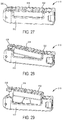
- FIG. 27 is a perspective view of an implant in a collapsed position according to another embodiment.
- FIG. 28 is a perspective view of the implant of FIG. 27 in an intermediate position according to one embodiment.
- FIG. 29 is a perspective view of the implant of FIG. 27 in an expanded position according to one embodiment.
- FIG. 30 is a side cross-section view of the implant of FIG. 27 in a collapsed position according to one embodiment.
- FIG. 31 is a side cross-section view of the implant of FIG. 27 in an intermediate position according to one embodiment.
- FIG. 32 is a side cross-section view of the implant of FIG. 27 in an expanded position according to one embodiment.
- FIG. 33 is a perspective view of a portion of the implant of FIG. 27 according to one embodiment.
- FIG. 34 is a cross-section view of the portion of the implant of FIG. 33 according to one embodiment.
- FIG. 35 is a side perspective view of an implant in a collapsed position according to another embodiment.
- FIG. 36 is a bottom perspective view of the implant of FIG. 35 according to one embodiment.
- FIG. 37 is a perspective view of the implant of FIG. 35 in an expanded position according to one embodiment.
- FIG. 38 is perspective view of the implant of FIG. 35 in an expanded position with bone screws according to one embodiment.
- FIG. 39 is an exploded view of the implant of FIG. 35 according to one embodiment.
- FIG. 40 is a cross-section view of the implant of FIG. 35 in a collapsed position according to one embodiment.
- FIG. 41 is a cross-section view of the implant of FIG. 35 in an expanded position according to one embodiment.
- FIG. 42 is a top view of the implant of FIG. 35 according to one embodiment.
- FIG. 43 is a front view of the implant of FIG. 35 according to one embodiment.
- FIG. 44 is a side view of the implant of FIG. 35 according to one embodiment.
- FIG. 45 is a perspective view of an implant in a collapsed position according to one embodiment.
- FIG. 46 is a perspective view of the implant of FIG. 45 in an expanded position according to one embodiment.
- FIG. 47 is a partial exploded view of the implant of FIG. 45 according to one embodiment.
- FIG. 48 is a partial exploded view of the implant of FIG. 45 according to one embodiment.
- FIG. 49 is a side view of the implant of FIG. 45 according to one embodiment.
- FIG. 50 is a cross-section view of the implant of FIG. 45 according to one embodiment.
- FIG. 51 is a top perspective view of the implant of FIG. 45 according to one embodiment.
- FIG. 52 is a bottom perspective view of the implant of FIG. 45 according to one embodiment.
- FIG. 53 is a partial exploded view of the implant of FIG. 45 according to one embodiment.
- FIG. 54 is a partial exploded view of the implant of FIG. 45 according to one embodiment.
- FIG. 55 is a perspective view of an expandable implant in a collapsed position according to another embodiment.
- FIG. 56 is another perspective view of the implant of FIG. 55 in a collapsed position according to one embodiment.
- FIG. 57 is a perspective view of the implant of FIG. 55 in an expanded position according to one embodiment.
- FIG. 58 is a side view of the implant of FIG. 55 in an expanded embodiment.
- FIG. 59 is a perspective view of the implant of FIG. 55 with bone screws inserted according to one embodiment.
- FIG. 60 is a perspective view of an expandable implant in a collapsed position according to another embodiment.
- FIG. 61 is a perspective view of the implant of FIG. 60 in an expanded position according to one embodiment.
- FIG. 62 is a bottom perspective view of the implant of FIG. 60 in an expanded position according to one embodiment.
- FIG. 63 is another bottom perspective view of the implant of FIG. 60 in an expanded position according to one embodiment.
- FIG. 64 is side perspective view of the implant of FIG. 60 in an expanded position with bone screws inserted according to one embodiment.
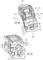
- FIG. 65 is a rear perspective view of the implant of FIG. 60 in an expanded position with bone screws inserted according to another embodiment.
- FIG. 66 is a perspective view of an expandable implant in a collapsed position according to one embodiment.
- FIG. 67 is a perspective view of the implant of FIG. 66 in an expanded position according to one embodiment.
- FIG. 68 is a front view of the implant of FIG. 66 in an expanded position according to one embodiment.
- FIG. 69 is a perspective view of the implant of FIG. 66 in an expanded position with bone screws inserted according to one embodiment.
- FIG. 70 is a side perspective view of an expandable implant in a collapsed position according to one embodiment.
- FIG. 71 is a cross section view of the implant of FIG. 70 is a collapsed position according to one embodiment.
- FIG. 72 is a side perspective view of the implant of FIG. 70 in an intermediate position according to one embodiment.
- FIG. 73 is a cross section view of the implant of FIG. 70 in an intermediate position according to one embodiment.
- FIG. 74 is side perspective view of the implant of FIG. 70 in an expanded position according to one embodiment.
- FIG. 75 is a cross section view of the implant of FIG. 70 in an expanded position according to one embodiment.
- FIG. 76 is another perspective view of the implant of FIG. 70 in an expanded position according to one embodiment.
- FIG. 77 is a partial cutaway view of the implant of FIG. 70 according to one embodiment.
- FIG. 78 is a side view of the implant of FIG. 70 according to another embodiment.
- FIG. 79 is a side perspective view of an expandable implant in a collapsed position according to one embodiment.
- FIG. 80 is a side perspective view of the implant of FIG. 79 in an expanded position according to one embodiment.
- FIG. 81 is a cross section view of the implant of FIG. 79 in a collapsed position according to one embodiment.
- FIG. 82 is a cross section view of the implant of FIG. 79 in an expanded position according to one embodiment.
- FIG. 83 is a partial cutaway view of the implant of FIG. 79 according to one embodiment.
- FIG. 84 is a partial exploded view of the implant of FIG. 79 according to one embodiment.
- FIG. 85 is another partial exploded view of the implant of FIG. 79 according to one embodiment.
- FIG. 86 is a front perspective view of an expandable implant in a collapsed position according to one embodiment.
- FIG. 87 is a front perspective view of the expandable implant of FIG. 86 in an expanded position according to one embodiment.
- FIG. 88 is a side perspective view of an expandable implant in a collapsed position according to one embodiment.
- FIG. 89 is a rear perspective view of the expandable implant of FIG. 88 according to one embodiment.
- FIG. 90 is a rear perspective view of the expandable implant of FIG. 88 and a manipulation device according to one embodiment.
- FIG. 91 is a detailed view of the expandable implant of FIG. 88 coupled to the manipulation device in a first position according to one embodiment.
- FIG. 92 is a top view of the expandable implant of FIG. 88 coupled to the manipulation device in a first position according to one embodiment.
- FIG. 93 is a top view of the expandable implant of FIG. 88 coupled to the manipulation device in an intermediate position according to one embodiment.
- FIG. 94 is a top view of the expandable implant of FIG. 88 coupled to the manipulation device in a second position according to one embodiment.
- FIG. 95 is a side perspective view of the expandable implant of FIG. 88 coupled to the manipulation device in a second position according to one embodiment.
- FIG. 96 is a side perspective view of the expandable implant of FIG. 88 coupled and locked to the manipulation device in a second position according to one embodiment.
- FIG. 97 is a top view of the expandable implant of FIG. 88 coupled and locked to the manipulation device in a second position according to one embodiment.
- FIG. 98 is a top view of the expandable implant of FIG. 88 uncoupled from the manipulation device according to one embodiment.
- FIG. 99 is a rear perspective view of the expandable implant of FIG. 88 uncoupled from the manipulation device according to one embodiment.
- the present disclosure relates to expandable and/or dynamic implants, including, but not limited to, interbody (between adjacent vertebrae), intravertebral-body (inside the vertebrae) and/or spinal stabilization devices that may or may not be used as interbody fusion cages or devices, interbody/intravertebral bodies/body stabilization devices and/or the like (e.g., spinal device(s)) for providing support, stabilization and/or promoting bone growth between or inside vertebrae or other portions of bone that have been destabilized or otherwise due to injury, illness and/or the like.
- spinal device(s) for providing support, stabilization and/or promoting bone growth between or inside vertebrae or other portions of bone that have been destabilized or otherwise due to injury, illness and/or the like.
- the present disclosure provides various versions of dynamic (expandable and/or expandable and retractable) interbody/intravertebral body devices that are usable in a spinal column or other areas of a human.
- the implant may be implanted or inserted into a human spine adjacent upper and lower vertebrae of the spine.
- the components of the implants disclosed herein may be made of any suitable material(s), including a variety of metals, plastics, composites, or other suitable bio-compatible materials.
- one or more components of the implants disclosed herein may be made of the same material, while in other embodiments, different materials may be used for different components of the various implants.
- Implant 10 is shown according to an exemplary embodiment.
- Implant 10 is usable, for example, between and/or within vertebral bodies of the spine, and may share many of the features of the other inter/intra-body implants discussed elsewhere herein. It should be understood that implant 10 may in some embodiments be usable in other portions of the body in addition to the spine, and all such applications are to be understood to be within the scope of the present disclosure.
- implant 10 includes a base member 12 and an adjustable member 14 adjustably coupled to the base member 12 .
- a control shaft 16 is received by the base member 12 and is retained by a retention pin 18 passing through a portion of the base member 12 .
- a first control member 20 and a second control member 22 are received on the control shaft 16 and are movable along the control shaft 16 to adjust a position of the adjustable member 14 between a collapsed position, as shown in FIG. 1 , and an expanded position, as shown in FIG. 2 .
- the base member 12 includes a front or first end 24 , a rear or second end 26 , and a central cavity 36 disposed between the first end 24 and the second end 26 .
- the base member 12 further includes a top surface 28 having ridges or projections 30 formed by corresponding grooves, a bottom surface 32 opposite the top surface 28 and having ridges or projections 34 formed by corresponding grooves, a first side 38 , and a second side 40 .
- the projections 30 , 34 are configured to engage adjacent portions of bone.
- the first side 38 defines a first side recess 42
- the second side 40 defines a second side recess 44 .
- a pin aperture 46 extends through one or both of first side 38 and second side 40 and is configured to receive the retention pin 18 (e.g., in a press fit or other manner).
- the second end 26 of the base member 12 includes a control bore 48 configured to receive a first portion of the control shaft 16 .
- the first end 24 of the base member 12 includes a control counterbore 50 (see FIG. 4 ) configured to receive a second portion of the control shaft 16 .
- the first end 24 of the base member 12 further includes a dovetail recess 58
- the second end 26 of the base member 12 further includes a dovetail recess 60 .
- the adjustable member 14 includes a front or first end 62 , a rear or second end 64 , and a central recess or cavity 78 positioned between the first end 62 and the second end 64 .
- a top cavity 84 (see FIG. 5 ) in the adjustable member 14 extends to the central cavity 78 .
- the adjustable member 14 further includes a top surface 66 having ridges or projections 68 formed by corresponding grooves, a bottom surface 70 including ridges or projections 72 (see FIG. 8 ) formed by corresponding grooves, a first side portion 80 , and a second side portion 82 .
- first and second side portions 80 , 82 have shapes generally corresponding to the shapes of the first and second side recesses 42 , 44 of base member 12 . In other embodiments, the first and second side portions 80 , 82 have shapes differing from the shapes of the first and second side recesses 42 , 44 of the base member 12 .
- the first end 62 of the adjustable member 14 further includes a dovetail projection 86
- the second end 64 of the adjustable member 14 further includes a dovetail projection 88 .
- the adjustable member 14 includes one or more control channels, such as a first control channel 74 and a second control channel 76 .
- the first control channel 74 receives the first control member 20
- the second control channel 76 receives the second control member 22 .
- the control members 20 , 22 are received in the control channels 74 , 76 in a sliding manner such that the control members 20 , 22 are able to translate within the control channels 74 , 76 .
- each control channel has a shape such that the control channel surrounds the control member and at least partially corresponds in shape to the control member.
- the control shaft 16 includes a head portion 90 , a tool port 92 disposed within the head portion 90 , and a retention groove 98 located at an end opposite the head portion 90 .
- the control shaft 16 further includes a first control thread 94 and a second control thread 96 .
- a non-threaded portion 100 may be located between the first control thread 94 and the second control thread 96 .
- the first control member 20 includes a body 102 , one or more flat portions 104 , and a first internal thread 106 .
- the second control member 22 includes a body 108 , one or more flat portions 110 , and a second internal thread 112 .
- the second control member 22 further includes a slotted portion 114 configured to enable passing the second control member 22 over a portion (e.g., non-threaded portion 100 ) of the control shaft 16 .
- the first control member 20 and the second control member 22 move or translate both along the control shaft 16 and within or on the first control channel 74 and the second control channel 76 .
- implant 10 is movable between a first, collapsed position, as shown in FIG. 1 , to a second, expanded position, shown in FIG. 2 .
- the adjustable member 14 In the first position, the adjustable member 14 is received within the central cavity 36 of the base member 12 .
- the dovetail projections 86 , 88 on the adjustable member 14 are received within the dovetail recesses 58 , 60 in the base member 12 (see FIG. 6 ).
- the projections and recesses have a relatively close fit to enable proper alignment between the adjustable member 14 and the base member 12 , while in other embodiments, the projections and recesses have a relatively loose fit to enable a desired angular offset between the adjustable member 14 and the base member 12 .
- the control shaft 16 is received by the base member 12 such that the retention groove 98 is positioned with the first end 24 of the base member 12 and the head portion 90 is positioned within the second end 26 of the base member 12 .
- the control shaft 16 is rotatable within the base member 12 , and the retention pin 18 extends through the first end 24 and into the retention groove 98 of the control shaft 16 to enable rotation of the control shaft 16 while inhibiting translation of the control shaft 16 relative to the base member 12 .
- the first control member 20 is received on the first control thread 94 of the control shaft 16
- the second control member 22 is received on the second control thread 96 of the control shaft 16 .
- the slot 114 enables passage of the second control member 22 over the non-threaded portion 100 of the control shaft 16 and subsequent threading of the second control member 22 onto the second control thread 96 .
- first control thread 94 and the second control thread 96 are threaded in opposite manners (e.g., left-handed and right-handed), such that upon rotation of the control shaft 16 , the control members 20 , 22 move in opposite directions along the control shaft 16 .
- the control shaft may be configured that rotation of the control shaft 16 in a first direction (e.g., clockwise) causes the first and second control members 20 , 22 to move toward each other, and rotation of the control shaft 16 in a second direction (e.g., counter-clockwise) causes the first and second control member 20 , 22 to move away from each other.
- FIGS. 4 and 5 show the control members 20 , 22 moving away from each other along the control shaft 16 .
- the adjustable member 14 is moved upward or downward due to the angled shape of the first and second control channels 74 , 76 .
- the rate of movement of the control members 20 , 22 , and therefore the adjustable member 14 can be adjusted by modifying the slope of the control channels 74 , 76 relative to the control shaft 16 .
- FIGS. 9A-9C schematic representations of the control shaft 16 , the first control channel 74 , and the second control channel 76 are shown according to various alternative embodiments.
- the first control channel 74 extends at a first angle 116 relative to the control shaft 16
- the second control channel 76 extends at a second angle 118 relative to the control shaft 16 .
- the first and second angles 116 , 118 define the rate at which first control member 20 and second control member 22 cause corresponding movement (e.g., expansion) of the first and second ends 62 , 64 of the adjustable member 14 relative to the base member 12 .
- FIG. 9A-9C schematic representations of the control shaft 16 , the first control channel 74 , and the second control channel 76 are shown according to various alternative embodiments.
- the first control channel 74 extends at a first angle 116 relative to the control shaft 16
- the second control channel 76 extends at a second angle 118 relative to the control shaft 16 .
- the first angle 116 and second angle 118 are approximately the same, and the control channels 74 , 76 define linear paths, such that the rates of movement of the first and second ends 62 , 64 of the adjustable member 14 are substantially the same and constant (assuming a constant rate of rotation of the control shaft 16 ).
- the first and second control channels 74 , 76 may extend in a parallel manner or be configured to extend upward at angles in the same general direction.
- one or both of the control channels 74 , 76 may define a non-linear channel. For example, as shown in FIG.
- the second control channel 76 defines a curved path, thereby providing a changing rate of movement of the second end 64 of adjustable member 14 .
- angles 116 , 118 may differ from each other to provide different amounts of movement and to suit a particular application.
- first control channel 74 and the second control channel 76 enables customization of the characteristics of the implant 10 in the second, expanded position.
- the control channels 74 , 76 may be configured such that in a fully expanded position of implant 10 , one of the first end 62 and the second end 64 of the adjustable member 14 is expanded to a greater degree than the opposing end.
- An example of such a configuration is reflected in FIG. 9C , and shown in greater detail with the embodiment of FIGS. 27-34 .
- Other configurations of the first and second control channels 74 , 76 are possible according to various alternative embodiments.
- implant 10 is positioned within a desired space (e.g., between adjacent portions of bone) while in the first, collapsed position, as shown in FIG. 1 .
- an appropriate tool may be used to engage tool recesses 56 and manipulate implant 10 into a desired position.
- a subsequent tool may be utilized to engage tool port 92 and rotate control shaft 16 to move adjustable member 14 to a desired degree of expansion.
- the adjustable member 14 may be utilized in a fully collapsed position, a fully expanded position, or any intermediate position therebetween.
- bone graft material may be delivered by way of, for example, access aperture 52 and placed into central cavity 36 .
- the various apertures in and through the base member 12 and adjustable member 14 may in some embodiments facilitate the growth of bone material in and around implant 10 to further stabilize the device.
- implant 10 may share various features with the other implants described herein, and be made of the same, similar, or different materials.
- various components of implant 10 may be made of metal, plastic, composites, or other suitable bio-compatible materials.
- implant 10 may be usable in connection with the spine or other parts of the body.
- Implant 210 may share many of the features of the other inter/intra-body implants discussed elsewhere herein. All such combinations of features are to be understood to be within the scope of the present disclosure.
- Implant 110 is generally similar to implant 10 in structure and function except that, while implant 10 expands to vary an implant height, implant 210 expands to vary an implant width.
- Implant 210 includes a base member 212 and an adjustable member 214 adjustably coupled to the base member 212 .
- a control shaft 216 is received by the base member 212 and is retained by a retention pin 218 passing through a portion of the base member 212 .
- a first control member 220 and a second control member 222 are received on the control shaft 216 and are movable along the control shaft 216 to adjust a position of the adjustable member 214 between a collapsed position, as shown in FIG. 10 , and an expanded position, as shown in FIG. 11 .
- the base member 212 includes a front or first end 224 , a rear or second end 226 , and a central cavity 236 disposed between the first end 224 and the second end 226 .
- the base member 212 further includes a top surface 228 having ridges or projections 230 formed by corresponding grooves, a bottom surface 232 opposite the top surface 228 and having ridges or projections 234 formed by corresponding grooves, a first side 238 , and a second side 240 .
- the projections 230 , 234 are configured to engage adjacent portions of bone.
- the first side 238 defines a plurality of recesses 244 .
- a pin aperture 246 extends through one or both of the first side 238 and the second side 240 and is configured to receive the retention pin 218 (e.g., in a press fit or other manner).
- the second end 226 of the base member 212 includes a control bore 248 configured to receive a first portion of the control shaft 216 .
- the first end 224 of the base member 212 includes a control counterbore 250 configured to receive a second portion of the control shaft 216 .
- the first end 224 of the base member 212 further includes a dovetail recess 258
- the second end 226 of the base member 212 further includes a dovetail recess 260 .
- the adjustable member 214 includes a front or first end 262 , a rear or second end 264 , and a central recess or cavity 278 positioned between the first end 262 and the second end 264 .
- a side cavity 284 in the adjustable member 214 extends to the central cavity 278 .
- the adjustable member 214 further includes a top surface 266 having ridges or projections 268 formed by corresponding grooves, a bottom surface 270 including ridges or projections 272 formed by corresponding grooves, a pair of top portions 280 , and a pair of bottom portions 282 .
- top and bottom portions 280 , 282 are configured to slide underneath or within the top and bottom portions of base member 212 when implant 210 is in the first, collapsed position.
- the first end 262 of the adjustable member 214 further includes a dovetail projection 286
- the second end 264 of the adjustable member 214 further includes a dovetail projection 288 .
- the adjustable member 214 includes one or more control channels, such as a first control channel 274 and a second control channel 276 .
- the first control channel 274 receives the first control member 220
- the second control channel 276 receives the second control member 222 .
- the control members 220 , 222 are received in or on the control channels 274 , 276 in a sliding manner such that the control members 220 , 222 are able to translate within the control channels 274 , 276 .
- each control channel has a shape such that the control channel surrounds the control member and at least partially corresponds in shape to the control member.
- Implant 210 is adjustable in a similar manner to implant 10 . However, while adjustment of implant 10 causes a change in height of the implant 10 , adjustment of the implant 210 causes a change in width of the implant 210 (while maintaining a constant height). As such, while during adjustment of the implant 10 , the top surface 66 of the adjustable member 14 may be offset from the top surface 28 of the base member 12 , during adjustment of implant 210 , the top surface 266 of the adjustable member 214 stays generally aligned with the top surface 228 of the base member 212 . As such, the implant 210 may be used to provide, for example, a more stable implant by increasing the footprint of the implant and engagement areas with adjacent portions of bone. The implantation of the implant 210 is otherwise similar to that of the implant 10 .
- implant 210 may share various features with the other implants described herein, and be made of the same, similar, or different materials.
- various components of implant 210 may be made of metal, plastic, composites, or other suitable bio-compatible materials.
- implant 210 may be usable in connection with the spine or other parts of the body.
- an implant 310 includes a base member 312 and an adjustable member 314 adjustably coupled to the base member 312 .
- a control shaft 316 is received by the base member 312 and is retained by a retention pin passing through a portion of the base member 312 .
- a first control member and a second control member are received on the control shaft 316 and are movable along the control shaft 316 to adjust a position of the adjustable member 314 between a collapsed position, as shown in FIG. 16 , and an expanded position, as shown in FIG. 17 .
- Bone screws 320 , 322 extend through base member 312 and adjustable member 314 .
- Implant 310 may share any combination of the features disclosed herein with respect to the other implants, and all such combinations of features are to be understood to be within the scope of the present disclosure.
- the implant 310 is generally rectangular in shape when in a first, collapsed position.
- the base member 312 includes a first bone screw support portion 324 having a first bone screw bore 326 configured to receive bone screw 320 .
- adjustable member 314 includes a second bone screw support portion 328 having a second bone screw bore 330 configured to receive bone screw 322 .
- the first bone screw support portion 324 and the second bone screw support portion 328 collectively form a proximal face 332 for implant 310 .
- the first bone screw bore 326 , the second bone screw bore 330 , and the control shaft 316 are accessible by way of the proximal face 332 of the implant 310 .
- the implant 310 may share various features with the other implants described herein, and be made of the same, similar, or different materials.
- various components of the implant 310 may be made of metal, plastic, composites, or other suitable bio-compatible materials.
- the implant 310 may be usable in connection with the spine or other parts of the body.
- an expandable implant 410 is shown according to an exemplary embodiment.
- the implant 410 is usable, for example, between and/or within vertebral bodies of the spine, and may share any or all of the features of the other inter/intra-body implants discussed elsewhere herein. All such combinations of features are to be understood to be within the scope of the present disclosure. It should be understood that the implant 410 may in some embodiments be usable in other portions of the body in addition to the spine, and all such applications are to be understood to be within the scope of the present disclosure.
- the implant 410 is substantially similar to the implant 10 in structure and function except as discussed herein with respect to the control members and corresponding control rails.
- the implant 410 includes a base member 412 and an adjustable member 414 adjustably coupled to the base member 412 .
- a control shaft 416 is received by the base member 412 and is retained by a retention pin 418 passing through a portion of the base member 412 .
- a first control member 420 and a second control member 422 are received on the control shaft 416 and are movable along the control shaft 416 to adjust a position of the adjustable member 414 between a collapsed position, as shown in FIG. 19 , and an expanded position, as shown in FIG. 23 .
- the adjustable member 414 includes one or more control rails, such as a first control rail 474 and a second control rail 476 .
- First control rail 474 receives first control member 420
- second control rail 476 receives second control member 422 .
- control members 420 , 422 are received on control rails 474 , 476 in a sliding manner such that the control members 420 , 422 are able to translate on the control rails 474 , 476 .
- the control rails 474 , 476 may define control channels on or in which the control members 420 , 422 are received.
- each control rail has a shape such that the control member surrounds all or a portion of the control rail and at least partially corresponds in shape to the control rail.
- the first control member 420 includes control arms 428 configured to engage the first control rail 474 .
- the second control member 422 includes control arms 430 configured to engage the second control rail 476 .
- the first control member 420 and the second control member 422 move or translate both along the control shaft 416 and along the first control rail 474 and the second control rail 476 .
- each control arm is substantially U-shaped and configured to wrap around an end portion of the corresponding control rail. In other embodiments, other shapes and/or configurations of control rails and control arms or other components may be utilized.
- the control members 420 , 422 Similar to implant 10 , and as shown in FIGS. 23 and 24 , as the control members 420 , 422 move along the control shaft 416 , the control members 420 , 422 further move along the control rails 474 , 476 , thereby causing relative movement of the adjustable member 414 and the base member 412 . As the control members 420 , 422 translate along the control shaft 416 , the adjustable member 414 is moved due to the orientation and shape of the first and second control rails 474 , 476 .
- the rate of movement of the control members 420 , 422 , and therefore adjustable member 414 can be adjusted by modifying the slope of the control rails 474 , 476 relative to the control shaft 416 , as discussed in greater detail elsewhere herein, including FIGS. 9A-9C .
- implant 410 may share various features with the other implants described herein, and be made of the same, similar, or different materials.
- various components of implant 410 may be made of metal, plastic, composites, or other suitable bio-compatible materials.
- implant 410 may be usable in connection with the spine or other parts of the body.
- an expandable implant 510 is shown according to an exemplary embodiment.
- the implant 510 is usable, for example, between and/or within vertebral bodies of the spine, and may share any or all of the features of the other inter/intra-body implants discussed elsewhere herein. All such combinations of features are to be understood to be within the scope of the present disclosure. It should be understood that the implant 510 may in some embodiments be usable in other portions of the body in addition to the spine, and all such applications are to be understood to be within the scope of the present disclosure.
- the implant 510 is substantially similar to implant 10 , with the exception of the configuration of the control channels as discussed below.
- the implant 510 includes a base member 512 and an adjustable member 514 adjustably coupled to the base member 512 .
- a control shaft 516 is received by the base member 512 and is retained by a retention pin 518 passing through a portion of the base member 512 .
- a first control member 520 and a second control member 522 are received on the control shaft 516 and are movable along the control shaft 516 to adjust a position of the adjustable member 514 between a collapsed position, as shown in FIGS. 27 and 30 , and an expanded position, as shown in FIGS. 29 and 32 .
- the adjustable member 514 includes a front or first end 530 , and a rear or second end 532 .
- the adjustable member 514 further includes one or more control channels, such as a first control channel 524 and a second control channel 526 .
- the first control channel 524 receives the first control member 520
- the second control channel 526 receives the second control member 522 .
- the control members 520 , 522 are received in the control channels 524 , 526 in a sliding manner such that the control members 520 , 522 are able to translate within the control channels 524 , 526 .
- each control channel has a shape such that the control channel surrounds the control member and at least partially corresponds in shape to the control member.
- the control members 520 , 522 move along the control shaft 516 , the control members 520 , 522 further move within the control channels 524 , 526 , thereby causing relative movement of the adjustable member 514 and the base member 512 .
- the adjustable member 514 is moved based on the shape of the first and second control channels 524 , 526 .
- the rate of movement of the control members 520 , 522 , and therefore the adjustable member 514 can be adjusted by modifying the slope of the control channels 524 , 526 relative to the control shaft 516 .
- the first control channel 524 extends at an angle relative to the control shaft 516 , and has a substantially linear form and constant slope, thereby providing a generally constant corresponding rate of movement of the first end 530 of the adjustable member 514 .
- the second control channel 526 includes a first channel portion 528 and a second channel portion 530 which extend at different angles relative to the control shaft 516 .
- the first channel portion 528 is generally parallel to the control shaft 516
- the second channel portion 530 extends at an angle similar to that of first control channel 524 .
- the second control channel 526 provides a non-constant rate of movement of second end 532 of the adjustable member 514 .
- FIGS. 27-32 illustrate the corresponding movement of the adjustable member 514 resulting from the differing configurations of the first control channel 524 and the second control channel 526 .
- the implant 510 is in a collapsed position, such that the control members 520 , 522 reside in the upper/inner—most positions within the first and second control channels 524 , 526 .
- FIGS. 28 and 31 illustrate implant 510 in an intermediate expanded position, where second control member 522 is positioned generally at the intersection of the first channel portion 528 and the second channel portion 530 . Due to the orientation of the first channel portion 528 , the second end 532 of adjustable member 514 has remained generally at the same height as that shown in FIGS.
- FIGS. 29-32 show the implant 510 in a fully expanded position, where control members 520 , 522 reside in the lower/outer—most positions within the first and second control channels 524 , 526 . Due to the angled configurations of both the first control channel 524 and the second channel portion 530 of the second control channel 526 , both the first end 530 and the second end 532 move relative to the base member 512 .
- implant 510 may facilitate accommodating a desired spinal curvature or other anatomical features where non-parallel supporting surfaces are suitable for a particular application.
- control channels and/or control rails herein may take any desired configuration to provide desired expansion and contraction characteristics for a particular implant.
- Implant 610 may share many of the features of the other inter/intra-body implants discussed elsewhere herein. All such combinations of features are to be understood to be within the scope of the present disclosure. Implant 610 is generally similar to the other implants disclosed herein in structure and function except that implant 610 utilizes a single control member/control channel configuration, and further utilizes a pivot pin about which an adjustable member pivots relative to a base member.
- implant 610 includes a base member 612 and an adjustable member 614 adjustably coupled to the base member 612 .
- a control shaft 616 is received by the base member 612 and is retained by a retention pin 618 (e.g., a pivot pin or member, retaining pin) passing through a portion of the base member 612 and/or the adjustable member 614 .
- a control member 620 is received on the control shaft 616 and is movable along the control shaft 616 to adjust a position of the adjustable member 614 between a collapsed position, as shown in FIGS. 35 and 36 , and an expanded position, as shown in FIGS. 37 and 38 .
- the base member 612 includes a front or first end 624 , a rear or second end 626 , and a central cavity 638 disposed between the first end 624 and the second end 626 .
- the base member 612 further includes a top surface 646 and a bottom surface 634 opposite the top surface 646 and having ridges or projections 636 formed by corresponding grooves.
- the projections 636 are configured to engage adjacent portions of bone.
- the base member 612 further includes a planar portion 628 .
- a first extension 630 is positioned at the first end 624 and extends upward from the planar portion 628
- a second extension 632 is positioned at the second end 626 and extends upward from the planar portion 628 .
- a pin aperture 640 extends through the first extension 630 and is configured to receive the retention pin 618 (e.g., in a press fit, sliding, or other manner).
- the second extension 632 includes a bone screw bore 650 configured to receive a bone screw 622 .
- the first extension 630 includes a first control bore 642 and the second extension includes a second control bore 644 . Control bores 642 , 644 receive opposing ends of the control shaft 616 .
- the adjustable member 614 includes a front or first end 652 , a rear or second end 654 , and cavities 664 extending through the adjustable member 614 and positioned between the first end 652 and the second end 654 .
- the adjustable member 614 further includes a top surface 656 having ridges or projections 658 formed by corresponding grooves, and a bottom surface 660 .
- the adjustable member 614 further includes pin apertures 668 configured to receive the retention pin 618 to enable movement (e.g., pivoting) of the adjustable member 614 relative to the base member 612 .
- the adjustable member includes a first bone screw support portion 670 including a bone screw bore 674 and a second bone screw support portion 672 having a bone screw bore 676 . As shown in FIG.
- the first and second bone screw support portions 670 , 672 of the adjustable member 614 and the second extension 632 of the base member 612 collectively form a front face of the implant 610 , such that the control shaft 616 and the bone screws 622 are accessible via the front face of the implant 610 (e.g., when the implant 610 is in a collapsed position).
- the adjustable member 614 includes one or more control channels, such as control channel 662 .
- the control channel 662 receives the control member 620 .
- the control member 620 is received in the control channel 662 in a sliding manner such that the control member 620 is able to translate within the control channel 662 .
- the control channel 662 has a shape such that the control channel 662 surrounds the control member 620 and at least partially corresponds in shape to the control member 620 .
- the control shaft 616 includes a head portion 678 , a tool port 680 disposed within the head portion 678 , and a retention groove 684 located at an end opposite the head portion 678 .
- the control shaft 616 further includes a control thread 682 .
- Non-threaded portions 686 may be located on one or both side of the control thread 682 .
- the control member 620 includes a body 688 , one or more flat portions 690 , and an internal thread 692 .
- the control member 620 further includes a slotted portion configured to enable passing the control member 620 over a portion (e.g., non-threaded portion 686 ) of the control shaft 616 .
- the control member 620 moves or translates both along the control shaft 616 and within or on the control channel 662 .
- control shaft 616 is received by the base member 612 such that the retention groove 684 is positioned with the first extension 630 of the base member 612 and the head portion 678 is positioned within the second extension 632 of the base member 612 .
- the control shaft 616 is rotatable within the base member 612 , and the retention pin 618 extends through the first extension 630 and into the retention groove 684 of the control shaft 616 to enable rotation of the control shaft 616 while inhibiting translation of the control shaft 616 relative to the base member 612 .
- the internal thread 692 of the control member 620 is received on the control thread 682 of the control shaft 616 such that as the control member 620 moves along the control shaft 616 , the control member 620 further moves within the control channel 662 , thereby causing relative movement (e.g., pivotal movement) of the adjustable member 614 relative to the base member 612 (e.g., about retention pin 618 ).
- FIGS. 40 and 41 show the control member 620 moving along the control shaft 616 .
- the adjustable member 614 pivots about the retention pin 618 .
- the rate of movement of the control member 620 and therefore the adjustable member 614 , can be adjusted by modifying the slope of the control channel 662 relative to the control shaft 616 .
- implant 610 is positioned within a desired space (e.g., between adjacent portions of bone) while in the first, collapsed position, as shown in FIG. 35 .
- an appropriate tool may be used to engage tool recesses 648 and manipulate implant 610 into a desired position.
- a subsequent tool may be utilized to engage tool port 680 and rotate control shaft 616 to pivot adjustable member 614 to a desired degree of expansion.
- the adjustable member 614 may be utilized in a fully collapsed position, a fully expanded position, or any intermediate position therebetween.
- One or more bone screws 622 may be screwed into adjacent portions of bone as shown in FIG. 38 .
- bone graft material may be delivered by way of, for example, apertures 664 or alternatively, by the space formed due to the expansion of adjustable member 614 .
- the various apertures in and through the base member 612 and adjustable member 614 may in some embodiments facilitate the growth of bone material in and around implant 610 to further stabilize the device.
- implant 610 may share various features with the other implants described herein, and be made of the same, similar, or different materials.
- various components of implant 610 may be made of metal, plastic, composites, or other suitable bio-compatible materials.
- implant 160 may be usable in connection with the spine or other parts of the body.
- Implant 710 may include any of the features shown and described with respect to the other expandable implants disclosed herein.
- implant 710 is in many ways similar to implant 10 , and may include any of the features of implant 10 .
- Implant 710 is usable, for example, between and/or within vertebral bodies of the spine, and may share many of the features of the other inter/intra-body implants discussed elsewhere herein. It should be understood that implant 710 may in some embodiments be usable in other portions of the body in addition to the spine, and all such applications are to be understood to be within the scope of the present disclosure.
- implant 710 includes a base member 712 and an adjustable member 714 adjustably coupled to the base member 712 .
- a control shaft 716 is received by the base member 712 and is retained by a retention member 718 passing through a portion of the base member 712 .
- Retention member 718 is in turn retained in place by a retention pin 719 , which may further be welded, press-fit, or otherwise secured in place, as shown in FIG. 54 .
- a first control member 720 and a second control member 722 are received on the control shaft 716 and are movable along the control shaft 716 to adjust a position of the adjustable member 714 between a collapsed position, as shown in FIG. 45 , and an expanded position, as shown in FIG. 46 .
- the base member 712 includes a front or first end 724 , a rear or second end 726 , and a central cavity 736 disposed between the first end 724 and the second end 726 .
- the base member 712 further includes a top surface 728 , a bottom surface 732 opposite the top surface 728 and having ridges or projections 734 formed by corresponding grooves, a first side 738 , and a second side 740 .
- the projections 734 are configured to engage adjacent portions of bone.
- the base member 712 further includes alignment guides 742 and alignment recesses 744 , which engage corresponding guides and recesses on adjustable member 714 .
- Limiting pin apertures 746 extends through one or both of first side 738 and second side 740 and are configured to receive limiting pins 747 (e.g., in a press fit or other manner). Limiting pins 747 engage corresponding projections 749 on adjustable member 714 to limit an amount of expansion of adjustable member 714 relative to base member 712 .
- the second end 726 of the base member 712 includes a control bore 748 configured to receive a first portion of the control shaft 716 .
- the first end 724 of the base member 712 includes a control counterbore 750 (see FIG. 50 ) configured to receive a second portion of the control shaft 716 .
- the adjustable member 714 includes a front or first end 762 , a rear or second end 764 , and a central recess or cavity 778 positioned between the first end 762 and the second end 764 .
- a top cavity 784 (see FIG. 5 ) in the adjustable member 714 extends to the central cavity 778 .
- the adjustable member 714 further includes a top surface 766 having ridges or projections 768 formed by corresponding grooves, and a bottom surface 770 including ridges or projections 772 (see FIG. 52 ) formed by corresponding grooves.
- Alignment guides 780 and alignment recesses 782 are received by alignment recesses 742 and alignment guides 741 of base member 712 to maintain a desired alignment between the base member 712 and the adjustable member 714 (e.g., to provide linear relative movement, permit non-linear relative movement, etc.).
- projections 749 are disposed within recesses 782 and are configured to engage limiting pins 747 to limit an amount of expansion of adjustable member 714 relative to base member 712 .
- the adjustable member 714 includes one or more control channels, such as a first control channel 774 and a second control channel 776 .
- the first control channel 774 receives the first control member 720
- the second control channel 776 receives the second control member 722 .
- the control members 720 , 722 are received in the control channels 774 , 776 in a sliding manner such that the control members 720 , 722 are able to translate within the control channels 774 , 776 .
- each control channel has a shape such that the control channel surrounds the control member and at least partially corresponds in shape to the control member.
- retention member 718 includes a surface 761 (see FIG.
- first control member 720 acts as a limit surface for first control member 720 , such that first control member 720 engages surface 761 at a maximum expansion position for adjustable member 714 .
- surface 761 acts to limit the maximum expansion of adjustable member 714 by limiting the degree of movement of first control member 720 (and therefore second control member 722 ) along control shaft 716 .
- the control shaft 716 includes a head portion 790 , a tool port 792 disposed within the head portion 790 , and a retention groove 798 located at an end opposite the head portion 790 .
- the control shaft 716 further includes a first control thread 794 and a second control thread 796 .
- a non-threaded portion 800 may be located between the first control thread 794 and the second control thread 796 .
- the first control member 720 includes a body, one or more flat portions, and a first internal thread.
- the second control member 722 includes a body, one or more flat portions, and a second internal thread.
- the second control member 722 further includes a slotted portion configured to enable passing the second control member 722 over a portion (e.g., non-threaded portion 800 ) of the control shaft 716 .
- the first control member 720 and the second control member 722 move or translate both along the control shaft 716 and within or on the first control channel 774 and the second control channel 776 .
- implant 710 is movable between a first, collapsed position, as shown in FIG. 45 , to a second, expanded position, shown in FIG. 46 .
- the adjustable member 714 In the first position, the adjustable member 714 is collapsed against the base member 712 .
- the alignment guides 741 and alignment recesses 742 on base member 712 are received by alignment recesses 780 and alignment guides 782 on adjustable member 714 .
- the alignment guides and recesses have a relatively close fit to enable proper alignment between the adjustable member 714 and the base member 712 , while in other embodiments, the alignment guides and recesses have a relatively loose fit to enable a desired angular offset between the adjustable member 714 and the base member 712 .
- the control shaft 716 is received by the base member 712 such that the retention groove 798 is positioned with the first end 724 of the base member 712 and the head portion 790 is positioned within the second end 726 of the base member 712 .
- the control shaft 716 is rotatable within the base member 712 , and the retention member 718 extends through the first end 724 and into the retention groove 798 of the control shaft 16 to enable rotation of the control shaft 716 while inhibiting translation of the control shaft 716 relative to the base member 712 .
- the first control member 720 is received on the first control thread 794 of the control shaft 716
- the second control member 722 is received on the second control thread 796 of the control shaft 716 .
- a slot enables passage of the second control member 722 over the non-threaded portion 800 of the control shaft 716 and subsequent threading of the second control member 722 onto the second control thread 796 (as discussed with respect to, for example, control member 22 shown in FIGS. 1-8 ).
- the first control thread 794 and the second control thread 796 are threaded in opposite manners (e.g., left-handed and right-handed), such that upon rotation of the control shaft 716 , the control members 720 , 722 move in opposite directions along the control shaft 716 .
- the control shaft 716 may be configured such that rotation of the control shaft 716 in a first direction (e.g., clockwise) causes the first and second control members 720 , 722 to move toward each other, and rotation of the control shaft 716 in a second direction (e.g., counter-clockwise) causes the first and second control member 720 , 722 to move away from each other.
- the first and second control members 720 , 722 are configured to translate in a same direction upon rotation of control shaft 716 .
- the control members 720 , 722 move along the control shaft 716 , the control members 720 , 722 further move within the control channels 774 , 776 , thereby causing relative movement of the adjustable member 714 and the base member 712 .
- the adjustable member 714 is moved upward or downward due to the angled shape of the first and second control channels 774 , 776 .
- the rate of movement of the control members 720 , 722 , and therefore the adjustable member 714 can be adjusted by modifying the slope of the control channels 774 , 776 relative to the control shaft 716 , as discussed in greater detail with respect to FIGS. 9A-9C .
- first control channel 774 and the second control channel 776 enables customization of the characteristics of the implant 710 in the second, expanded position.
- the control channels 774 , 776 may be configured such that in a fully expanded position of implant 710 , one of the first end 762 and the second end 764 of the adjustable member 714 is expanded to a greater degree than the opposing end.
- An example of such a configuration is reflected in FIG. 9C , and shown in greater detail with the embodiment of FIGS. 27-34 .
- Other configurations of the first and second control channels 774 , 776 are possible according to various alternative embodiments. All such modifications and features are to be understood to be within the scope of the present disclosure and may form part of any of the expandable implants disclosed herein.
- implant 710 is positioned within a desired space (e.g., between adjacent portions of bone) while in the first, collapsed position, as shown in FIG. 45 .
- an appropriate tool may be used to engage tool recesses 756 and manipulate implant 710 into a desired position.
- a subsequent tool may be utilized to engage tool port 792 and rotate control shaft 716 to move adjustable member 714 to a desired degree of expansion.
- the adjustable member 714 may be utilized in a fully collapsed position, a fully expanded position, or any intermediate position therebetween.
- bone graft material may be delivered by way of, for example, access aperture 752 (see FIG. 49 ) and placed into central cavity 736 .
- the various apertures in and through the base member 712 and adjustable member 714 may in some embodiments facilitate the growth of bone material in and around implant 710 to further stabilize the device.
- side apertures 752 may extend through one or both sides of the base member 712 and the adjustable member 714 and communicate with an interior of implant 710 to promote bone growth, etc.
- aperture 784 in adjustable member 714 and apertures 751 in the base member 712 provide access to the interior of implant 710 via the top/bottom of implant 710 .
- control member 716 may include an access port 791 accessible by way of tool port 792 that is in fluid communication with the interior of implant 710 and enables delivery of bone graft or other material to the interior of implant 710 (e.g., by way of a tool, etc.).
- implant 710 may share various features with the other implants described herein, and be made of the same, similar, or different materials.
- various components of implant 710 may be made of metal, plastic, composites, or other suitable bio-compatible materials.
- implant 710 may be usable in connection with the spine or other parts of the body.
- an implant 910 includes a base member 912 and an adjustable member 914 is adjustably coupled to the base member 912 .
- a control shaft 916 is received by the base member 912 and may be retained by a retention pin passing through a portion of the base member 912 .
- a first control member 920 and a second control member 922 are received on the control shaft 916 and are movable along the control shaft 916 to adjust a position of the adjustable member 914 between a collapsed position, as shown in FIGS. 55-56 , and an expanded position, as shown in FIGS. 57-59 .
- Bone screws 921 , 923 extend through base member 912 and adjustable member 914 (see FIG. 59 ).
- Implant 910 may include any combination of the features disclosed herein with respect to the other implants, and all such combinations of features are to be understood to be within the scope of the present disclosure, particularly, but not limited to, those features of implant 310 shown and described with respect to FIGS. 16-18 .
- a substantial portion of implant 910 is generally rectangular in shape when in a first, collapsed position.
- the base member 912 includes a first bone screw support portion or extension 924 having a first bone screw bore 926 configured to receive bone screw 921 .
- adjustable member 914 includes a second bone screw support portion or extension 928 having a second bone screw bore 930 configured to receive bone screw 923 .
- the first extension 924 and the second extension 928 collectively form a proximal face 932 (see FIG. 58 ) for implant 910 with the corresponding end portions of base member 912 and adjustable member 914 .
- the first bone screw bore 926 , the second bone screw bore 930 , and the control shaft 916 are accessible by way of the proximal face 932 of the implant 910 .
- extensions 924 , 928 extend in generally opposite directions relative to the remaining portions of the base member 912 and the adjustable member 914 (e.g., in a perpendicular fashion, in an angled fashion, etc.). As such, extensions 924 , 928 may act as to limit the insertion of implant 910 into a vertebral or other space by way of extensions 924 , 928 interfacing with adjacent portions of bone. Furthermore, extensions 924 , 928 and bone screw bores 926 , 930 may be configured such that bone screws 921 , 923 extend in a generally parallel manner to the longitudinal axis of implant 910 (see FIG. 59 ). This configuration may facilitate fastening screws 921 , 923 into adjacent portions of bone due to the alignment of the screws with an incision and/or the implant.
- implant 910 may include lower alignment guides 940 and lower alignment recesses 942 provided on base member 912 that are configured to be received by corresponding upper alignment recesses 946 and upper alignment guides 944 provided on adjustable member 914 to maintain a desired alignment (e.g., linear, non-linear, etc.) between adjustable member 914 and base member 912 .
- the alignment guides and recesses may be provide on both sides of implant 910 , and any suitable number of guides and recesses may be utilized.
- implant 910 includes a central cavity 950 that is accessible (e.g., to promote bone growth, to receive bone growth material, etc.) by way of side apertures 952 , which may be provide on one or both sides of base member 912 and/or adjustable member 914 .
- Implant may further include a top aperture 954 to provide access to the central cavity 950 .
- implant 910 may have a relatively flat profile, such that the width of the implant 910 is substantially greater than the height of the main portion or body of implant 910 excluding the extensions 924 , 928 .
- the width of the main body of implant 910 may be two, three, four, or more times the height.
- a flatter profile may provide a more stable implant.
- the first and second control members 920 , 922 may be flush with or adjacent the top and/or bottom surfaces of implant 910 , and the corresponding control channels may open up to the top and/or bottom surfaces of implant 910 .
- the implant 910 may share various features with the other implants described herein, and be made of the same, similar, or different materials.
- various components of the implant 910 may be made of metal, plastic, composites, or other suitable bio-compatible materials.
- the implant 910 may be usable in connection with the spine or other parts of the body.
- Implant 1010 may include many of the features of the other inter/intra-body implants discussed elsewhere herein, particularly implant 610 shown and described with respect to FIGS. 35-44 . All such combinations of features are to be understood to be within the scope of the present disclosure.
- Implant 1010 is generally similar to the other implants disclosed herein in structure and function except that implant 1010 utilizes a single control member/control channel configuration, and further utilizes a pivot pin about which an adjustable member pivots relative to a base member.
- implant 1010 includes a base member 1012 and an adjustable member 1014 adjustably coupled to the base member 1012 .
- a control shaft 1016 is received by the base member 1012 and is retained by a retention pin 1018 (e.g., a pivot pin or member, retaining pin) passing through a portion of the base member 1012 and/or the adjustable member 1014 .
- a control member 1020 is received on the control shaft 1016 and is movable along the control shaft 1016 to adjust a position of the adjustable member 1014 between a collapsed position, as shown in FIG. 60 , and an expanded position, as shown in FIG. 61 .
- the base member 1012 includes a front or first end 1024 , a rear or second end 1026 , and a central cavity 1039 disposed between the first end 1024 and the second end 1026 .
- the base member 1012 further includes a top surface 1046 and a bottom surface 1034 opposite the top surface 1046 .
- the top and bottom surfaces 1046 , 1034 may include ridges or projections formed by corresponding grooves, as similarly shown in FIGS. 35-44 . The projections are configured to engage adjacent portions of bone.
- the base member 1012 further includes a bottom portion 1028 .
- a first extension 1030 is positioned at a first side and extends upward from the bottom portion 1028
- a second extension 1032 is positioned at a second side and extends upward from the bottom portion 1028
- Extensions 1030 , 1032 include curved lateral surfaces 1033 (see FIG. 61 ) configured to engage corresponding curved surfaces 1035 (see FIG. 63 ) within recesses 1036 formed in adjustable member 1014 to maintain a desired pivotal alignment during movement of adjustable member 1014 .
- a pin aperture 1068 extends through the bottom portion 1028 and is configured to receive the retention pin 1018 (e.g., in a press fit, sliding, or other manner).
- a front extension 1038 includes a bone screw bore 1050 configured to receive a bone screw 1022 .
- the front extension 1038 includes a control bore 1042 configured to receive a head portion of the control shaft 1016 .
- the adjustable member 1014 includes a front or first end 1052 , a rear or second end 1054 , and cavities 1064 extending through the adjustable member 1014 and positioned between the first end 1052 and the second end 1054 (see FIG. 61 ).
- the adjustable member 1014 further includes a top surface 1056 that may include ridges or projections formed by corresponding grooves.
- the adjustable member 1014 further includes pin apertures 1068 (see FIG. 65 ) configured to receive the retention pin 1018 to enable movement (e.g., pivoting) of the adjustable member 1014 relative to the base member 1012 .
- the adjustable member includes a first bone screw support portion 1070 including a bone screw bore 1074 and a second bone screw support portion 1072 having a bone screw bore 1076 .
- the first and second bone screw support portions 1070 , 1072 of the adjustable member 1014 and the front extension 1038 of the base member 1012 collectively form a front face of the implant 1010 , such that the control shaft 1016 and the bone screws 1022 are accessible via the front face of the implant 1010 (e.g., when the implant 1010 is in a collapsed position).
- the first and second bone screw support portions 1070 , 1072 and the front extension 1038 may be sized and spaced relative to each other so as to prevent undesired relative lateral movement between base member 1012 and adjustable member 1014 .
- the adjustable member 1014 includes one or more control channels, such as control channel 1062 .
- the control channel 1062 receives the control member 1020 .
- the control member 1020 is received in the control channel 1062 in a sliding manner such that the control member 1020 is able to translate within the control channel 1062 .
- the control channel 1062 has a shape such that the control channel 1062 surrounds the control member 1020 and at least partially corresponds in shape to the control member 1020 .
- the control shaft 1016 may include the features of control shaft 616 disclosed herein, and may include a head portion, a tool port disposed within the head portion, and a retention groove located at an end opposite the head portion. In some embodiments, the control shaft 1016 further includes a control thread 1082 . Non-threaded portions may be located on one or both side of the control thread 1082 .
- the control member 1020 may include the features of control member 620 , and may include a body, one or more flat portions, and an internal thread. In some embodiments, the control member 1020 further includes a slotted portion configured to enable passing the control member 1020 over a portion (e.g., a non-threaded portion) of the control shaft 1016 . The control member 1020 moves or translates both along the control shaft 1016 and within or on the control channel 1062 .
- control shaft 1016 is received by the base member 1012 such that the head portion of control shaft 1016 is positioned within the front extension 1038 of the base member 1012 .
- control shaft 1016 is rotatable within the base member 1012 , and a retention pin (e.g., retention pin 1018 ) extends into a retention groove of the control shaft 1016 to enable rotation of the control shaft 1016 while inhibiting translation of the control shaft 1016 relative to the base member 1012 .
- a retention pin e.g., retention pin 1018
- the internal thread of the control member 1020 is received on the control thread 1082 of the control shaft 1016 such that as the control member 1020 moves along the control shaft 1016 , the control member 1020 further moves within the control channel 1062 , thereby causing relative movement (e.g., pivotal movement) of the adjustable member 1014 relative to the base member 1012 (e.g., about retention pin 1018 ). As the control member 1020 translates along the control shaft 1016 , the adjustable member 1014 pivots about the retention pin 1018 . The rate of movement of the control member 1020 , and therefore the adjustable member 1014 , can be adjusted by modifying the slope of the control channel 1062 relative to the control shaft 1016 .
- implant 1010 is positioned within a desired space (e.g., between adjacent portions of bone) while in the first, collapsed position, as shown in FIG. 60 .
- an appropriate tool may be used to engage tool recesses (similar to tool recesses 648 ) and manipulate implant 1010 into a desired position.
- a subsequent tool may be utilized to engage control shaft 1016 to pivot adjustable member 1014 to a desired degree of expansion.
- the adjustable member 1014 may be utilized in a fully collapsed position, a fully expanded position, or any intermediate position therebetween.
- One or more bone screws 1022 may be screwed into adjacent portions of bone as shown in FIG. 64 .
- bone graft material may be delivered by way of, for example, apertures 1064 or alternatively, by the space formed due to the expansion of adjustable member 1014 .
- the various apertures in and through the base member 1012 and adjustable member 1014 may in some embodiments facilitate the growth of bone material in and around implant 1010 to further stabilize the device.
- implant 1010 may share various features with the other implants described herein, and be made of the same, similar, or different materials.
- various components of implant 1010 may be made of metal, plastic, composites, or other suitable bio-compatible materials.
- implant 1010 may be usable in connection with the spine or other parts of the body.
- Implant 1110 may include many of the features of the other inter/intra-body implants discussed elsewhere herein, particularly those features of implant 210 shown and described with respect to FIGS. 10-15 . All such combinations of features are to be understood to be within the scope of the present disclosure. Implant 1110 is generally similar to implant 210 in structure and function except that implant 1110 includes extensions to receive bone screws.
- Implant 1110 includes a base member 1112 and an adjustable member 1114 adjustably coupled to the base member 1112 .
- a control shaft 1116 is received by the base member 1112 and is retained by a retention pin 1118 passing through a portion of the base member 1112 .
- a first control member and a second control member are received on the control shaft 1116 and are movable along the control shaft 1116 to adjust a position of the adjustable member 1114 between a collapsed position, as shown in FIG. 66 , and an expanded position, as shown in FIG. 67 .
- implant 1110 further includes a flange portion or extension 1120 .
- Extension 1120 extends from a main body portion 1122 of base member 1112 and includes an upper extension 1124 and a lower extension 1126 .
- Upper extension 1124 includes a first bone screw bore 1128
- lower extension 1126 includes a second bone screw bore 1130 .
- Extension 1120 further includes an aperture 1133 and a control bore 1134 .
- Implant 1110 is adjustable in a similar manner to implant 10 . However, while adjustment of implant 10 causes a change in height of the implant 10 , adjustment of the implant 1110 causes a change in width of the implant 1110 (while maintaining a constant height). As such, while during adjustment of the implant 10 , the top surface of the adjustable member 14 may be offset from the top surface of the base member 12 , during adjustment of implant 1110 , the top surface of the adjustable member 1114 stays generally aligned with the top surface of the base member 1112 .
- the implant 1110 may be used to provide, for example, a more stable implant by increasing the footprint of the implant and engagement areas with adjacent portions of bone.
- the implantation of the implant 1110 is otherwise similar to that of the implant 10 and the other implants noted herein.
- extensions 1124 , 1126 extend in generally opposite directions relative to main portion 1122 of the base member 1112 (e.g., in a perpendicular fashion, in an angled fashion, etc.). As such, extensions 1124 , 1126 may act as to limit the insertion of implant 1110 into a vertebral or other space by way of extensions 1124 , 1126 interfacing or interfering with adjacent portions of bone. Furthermore, extensions 1124 , 1126 and bone screw bores 1128 , 1130 may be configured such that bone screws 1132 extend in a generally parallel manner to the longitudinal axis of implant 1110 (see FIG. 69 ). This configuration may facilitate fastening bone screws 1132 into adjacent portions of bone due to the alignment of the screws with an incision and/or the implant.
- implant 1110 may share various features with the other implants described herein, and be made of the same, similar, or different materials.
- various components of implant 1110 may be made of metal, plastic, composites, or other suitable bio-compatible materials.
- implant 1110 may be usable in connection with the spine or other parts of the body.
- an expandable implant 1210 is shown according to an exemplary embodiment.
- the implant 1210 is usable, for example, between and/or within vertebral bodies of the spine, and may include any or all of the features of the other inter/intra-body implants discussed elsewhere herein. All such combinations of features are to be understood to be within the scope of the present disclosure. It should be understood that the implant 1210 may in some embodiments be usable in other portions of the body in addition to the spine, and all such applications are to be understood to be within the scope of the present disclosure.
- the implant 1210 is in many ways similar to implant 510 , and may include any of the features of implant 510 or the other implants disclosed herein.
- the implant 1210 includes a base member 1212 and an adjustable member 1214 adjustably coupled to the base member 1212 .
- a control shaft 1216 is received by the base member 1212 and is retained by a retention pin 1218 passing through a portion of the base member 1212 .
- a first control member 1220 and a second control member 1222 are received on the control shaft 1216 and are movable along the control shaft 1216 to adjust a position of the adjustable member 1214 between a collapsed position, as shown in FIGS. 70-71 , and an expanded position, as shown in FIGS. 74-75 .
- expansion due to the control shaft 1216 may enable fluid communication (e.g., for the delivery of bone growth material, etc.) between an exterior and an interior of implant 1210 .
- the adjustable member 1214 includes a front or first end 1230 , and a rear or second end 1232 .
- the adjustable member 1214 further includes one or more control channels, such as a first control channel 1224 and a second control channel 1226 .
- the first control channel 1224 receives the first control member 1220
- the second control channel 1226 receives the second control member 1222 .
- the control members 1220 , 1222 are received in the control channels 1224 , 1226 in a sliding manner such that the control members 1220 , 1222 are able to translate within the control channels 1224 , 1226 .
- each control channel has a shape such that the control channel surrounds the control member and at least partially corresponds in shape to the control member.
- the control members 1220 , 1222 move along the control shaft 1216 , the control members 1220 , 1222 further move within the control channels 1224 , 1226 , thereby causing relative movement of the adjustable member 1214 and the base member 1212 .
- the adjustable member 1214 is moved based on the shape of the first and second control channels 1224 , 1226 .
- the rate of movement of the control members 1220 , 1222 , and therefore the adjustable member 1214 can be adjusted by modifying the slope of the control channels 1224 , 1226 relative to the control shaft 1216 .
- the first control channel 1224 extends at an angle relative to the control shaft 1216 , and has a substantially linear form and constant slope, thereby providing a generally constant corresponding rate of movement of the first end 1230 of the adjustable member 1214 .
- the second control channel 1226 includes a first channel portion 1228 and a second channel portion 1231 which extend at different angles relative to the control shaft 1216 .
- the first channel portion 1228 is generally parallel to the control shaft 1216
- the second channel portion 1231 extends at an angle similar to that of first control channel 1224 .
- the second control channel 1226 provides a non-constant rate of movement of second end 1232 of the adjustable member 1214 .
- FIGS. 70-75 illustrate the corresponding movement of the adjustable member 1214 resulting from the differing configurations of the first control channel 1224 and the second control channel 1226 .
- the implant 1210 is in a collapsed position, such that the control members 1220 , 1222 reside in the upper positions within the first and second control channels 1224 , 1226 .
- FIGS. 72-73 illustrate implant 1210 in an intermediate expanded position, where second control member 1222 is positioned generally at the intersection of the first channel portion 1228 and the second channel portion 1231 . Due to the orientation of the first channel portion 1228 , the second end 1232 of adjustable member 1214 has moved downward relative to the height as that shown in FIGS.
- FIGS. 74-75 show the implant 1210 in a fully expanded position, where control members 1220 , 1222 reside in the lower/outer—most positions within the first and second control channels 1224 , 1226 . Due to the angled configurations of both the first control channel 1224 and the second channel portion 1231 of the second control channel 1226 , both the first end 1230 and the second end 1232 move relative to the base member 1212 .
- implant 1210 includes features intended to facilitate non-linear movement of adjustment member 1214 relative to base member 1212 .
- a pin 1240 e.g., a projection, etc.
- the pin 1240 may rotate and/or translate within the slot 1242 .
- Pin 1240 and a slot 1242 limit the range of relative motion between adjustable member 1214 and base member 1212 .
- base member 1212 may include an alignment guide 1244 (e.g., an upstanding wall portion, etc.) received within an alignment recess 1246 in adjustable member 1214 .
- Alignment guide 1244 and alignment recess 1246 are configured such that in a first, collapsed position, a first side of alignment guide 1244 engages a first side of recess 1246 (see FIG. 70 ), and in an intermediate position a second side of alignment guide 1244 engages a second side of recess 1246 (see FIG. 72 ). In the fully expanded position, the alignment guide 1244 and recess 1246 may disengage due to the separation of the adjustable member 1214 and the base member 1212 .
- implant 1210 includes one or more apertures intended to provide fluid communication (e.g., for the delivery of bone growth material, etc.) between an exterior and an interior of implant 1210 .
- implant 1210 includes one or more apertures 1250 extending from an exterior of implant 1210 to an interior.
- Aperture 1250 may be formed in base member 1212 , adjustable member 1214 , or as shown in FIG. 78 , collectively formed by members 1212 , 1214 .
- Providing an implant with adjustment features such as those provided by implant 1210 may facilitate accommodating a desired spinal curvature or other anatomical features where non-parallel supporting surfaces are suitable for a particular application.
- providing an implant with adjustment features such as those provided by implant 1210 may facilitate fluid delivery/fluid ingress into the implant.
- the control channels and/or control rails herein may take any desired configuration to provide desired expansion and contraction characteristics for a particular implant.
- an expandable implant 1310 is shown according to an exemplary embodiment.
- the implant 1310 is usable, for example, between and/or within vertebral bodies of the spine, and may include any or all of the features of the other inter/intra-body implants discussed elsewhere herein. All such combinations of features are to be understood to be within the scope of the present disclosure. It should be understood that the implant 1310 may in some embodiments be usable in other portions of the body in addition to the spine, and all such applications are to be understood to be within the scope of the present disclosure.
- the implant 1310 is in many ways similar to implant 410 , and may include any of the features of implant 410 or the other implants disclosed herein.
- the implant 1310 includes a base member 1312 and an adjustable member 1314 adjustably coupled to the base member 1312 .
- a control shaft 1316 is received by the base member 1312 and is retained by a retention pin 1318 passing through a portion of the base member 1312 to be received by a groove 1321 on the control shaft 1316 .
- the groove 1321 is configured to allow rotational motion of the control shaft 1316 while preventing lateral (e.g., side to side, in and out) translation of the control shaft 1316 .
- a first control member 1320 and a second control member 1322 are received on the control shaft 1316 and are movable along the control shaft 1316 to adjust a position of the adjustable member 1314 between a collapsed position, as shown in FIG. 79 , and an expanded position, as shown in FIG. 80 .
- the adjustable member 1314 includes a front or first end 1330 , and a rear or second end 1332 .
- the adjustable member 1314 further includes one or more control channels, such as first control channel 1324 and a second control channel 1326 .
- the first control channel 1324 receives the first control member 1320
- the second control channel 1326 receives the second control member 1322 .
- One or more retention pins 1317 may be received by the base member 1312 and prevent the adjustable member 1314 from becoming uncoupled from the base member 1312 , as shown in FIG. 85 .
- the retention pins 1317 may contact channels 1313 and 1315 of the adjustable member 1314 to prevent the adjustable member 1314 from extending further.
- the channels 1313 and 1315 may align the adjustable member 1314 to the base member 1312 and further prevent the adjustable member 1314 from uncoupling from the base member 1312 . Further, the channels 1313 and 1315 may define an amount of expansion allowable for the adjustable member 1314 .
- Retention pin 1319 may be received by slot 1311 of the base member 1312 and limit translation of the first control member 1320 , as shown in FIG. 81 . Further, one or more retention pins 1318 may be received by the base member 1312 and contact the groove 1321 to secure the control shaft 1316 , as shown in FIG. 84 .
- control members 1320 , 1322 are received in the first control channels 1324 , 1326 in a sliding manner such that the control members 1320 , 1322 are able to translate within the control channels 1324 , 1326 .
- each control channel has a shape such that the control channel surrounds the control member and at least partially corresponds in shape to the control member.
- the control members 1320 , 1322 are rhomboid prisms configured to engage the first and second control channels 1324 , 1326 .
- the control members 1320 , 1322 include one or more flat portions 1302 - 1306 , and an internal thread 1308 . Relative to other shapes, rhomboidal control members may provide greater surface contact for the first and second control channels 1324 , 1326 to increase the area over which an expanding force acts, thereby reducing part fatigue and increasing part lifetime.
- control members 1320 , 1322 move along the control shaft 1316 , the control members 1320 , 1322 further move within the control channels 1324 , 1326 , thereby causing relative movement of the adjustable member 1314 and the base member 1312 .
- the adjustable member 1314 is moved based on the shape of the first and second control channels 1324 , 1326 .
- the rate of movement of the control members 1320 , 1322 , and therefore the adjustable member 1314 can be adjusted by modifying the slope of the control channels 1324 , 1326 relative to the control shaft 1316 and/or by modifying the thread (e.g., lead, pitch, etc.) of the control shaft 1316 to cause greater or lesser translation of the control members 1320 , 1322 for the same amount of rotation of the control shaft 1316 .
- implant 1310 includes one or more apertures intended to provide fluid communication (e.g., for the delivery of bone growth material, etc.) between an exterior and an interior of implant 1310 .
- implant 1310 includes one or more apertures 1350 extending from an exterior of implant 1310 to an interior.
- Aperture 1350 may be formed in base member 1312 or adjustable member 1314 and may extend through a top, bottom, side, or other surface.
- an expandable implant 1410 is shown according to an exemplary embodiment.
- the implant 1410 is usable, for example, between and/or within vertebral bodies of the spine, and may include any or all of the features of the other inter/intra-body implants discussed elsewhere herein. All such combinations of features are to be understood to be within the scope of the present disclosure. It should be understood that the implant 1410 may in some embodiments be usable in other portions of the body in addition to the spine, and all such applications are to be understood to be within the scope of the present disclosure.
- the implant 1410 is in many ways similar to implant 1310 , and may include any of the features of implant 1310 or the other implants disclosed herein.
- the implant 1410 includes a base member 1412 and an adjustable member 1414 adjustably coupled to the base member 1412 .
- a control shaft 1416 is received by the base member 1412 .
- a first control member 1420 and a second control member 1422 are received on the control shaft 1416 and are movable along the control shaft 1416 to adjust a position of the adjustable member 1414 between a collapsed position, as shown in FIG. 86 , and an expanded position, as shown in FIG. 87 .
- the implant 1410 includes a front or first end 1460 , and a back or second end 1462 .
- the implant 1410 is substantially curved such that the sides 1427 and 1429 are curved between a first end 1460 and a second end 1462 .
- a curvature of the implant 1410 is “banana” shaped.
- the implant 1410 includes a front or first side 1427 , and a rear or second side 1429 .
- the first side 1427 of the base member 1412 has a first height 1431 and the second side 1429 of the base member 1412 has a second height 1433 .
- the first height 1431 and the second height 1433 are different.
- the second height 1433 may be greater than the first height 1431 such that the implant 1410 is substantially wedge shaped.
- the first side 1427 of the adjustable member 1414 has a first height 1441 and the second side 1429 of the adjustable member 1414 has a second height 1443 .
- Providing an implant with forms such as those provided by implant 1410 may facilitate accommodating a desired spinal curvature or other anatomical features where non-parallel supporting surfaces are suitable for a particular application.
- the sides (e.g., first and second side 1427 and 1429 ) of base member 1412 and/or adjustable member 1414 described herein may take any desired height to provide desired supporting slope for a particular implant.
- providing an implant with a curvature such as that of the implant 1410 may facilitate accommodating different shapes of bone members or other anatomical features that are substantially non-straight in form.
- an expandable implant 1510 is shown according to an exemplary embodiment.
- the implant 1510 is usable, for example, between and/or within vertebral bodies of the spine, and may include any or all of the features of the other inter/intra-body implants discussed elsewhere herein. All such combinations of features are to be understood to be within the scope of the present disclosure. It should be understood that the implant 1510 may in some embodiments be usable in other portions of the body in addition to the spine, and all such applications are to be understood to be within the scope of the present disclosure.
- the implant 1510 is in many ways similar to implant 1410 , and may include any of the features of implant 1410 or the other implants disclosed herein. For example, implant 1510 may be substantially identical to implant 1410 with the exception of the manipulation features disclosed below.
- the implant 1510 includes a base member 1512 and an adjustable member 1514 adjustably coupled to the base member 1512 .
- a control shaft 1516 is received by the base member 1512 .
- the base member 1512 includes an attachment member 1560 configured to allow a manipulative accessory 1580 to couple to the implant 1510 and thereby manipulate the implant 1510 .
- the attachment member 1560 includes a bottom or first segment 1562 and a top or second segment 1564 .
- the segments 1562 , 1564 include control channels 1563 and 1565 , respectively.
- the control channel 1563 may be located on an upper horizontal surface of the segment 1562 and the control channel 1565 may be located on a lower horizontal surface of the segment 1564 .
- the base member 1512 includes control channel 1561 .
- the control channel 1561 may be located on a vertical surface of the base member 1512 .
- the control channels 1561 , 1563 , and 1565 are configured to receive and couple to coupling member 1582 of manipulative accessory 1580 .
- Each control channel 1561 , 1563 , and 1565 has a shape such that the control channels 1561 , 1563 , and 1565 surround the coupling member 1582 and at least partially corresponds in shape to the coupling member 1582 .
- the attachment member 1560 is curved such that an orientation of the implant 1510 changes as the coupling member 1582 is inserted into the attachment member 1560 .
- the attachment member 1560 includes a dovetail recess and the coupling member 1582 includes a dovetail projection.
- the attachment member 1560 may have a slotted opening to receive the coupling member 1582 , as shown in FIG. 91 .
- the attachment member 1560 may be configured to receive the manipulative accessory 1580 at an angle (e.g., such that a longitudinal axis of the implant is axially offset from the manipulative accessory).
- the attachment member 1560 may receive the manipulative accessory 1580 at an 80° angle, as defined between an axis of the implant 1510 and an axis of the manipulative accessory 1580 .
- the angle is different (e.g., 70°, 90°, etc.).
- the base member 1512 includes one or more control channels, for example guide 1570 .
- the guide 1570 is configured to receive a manipulative accessory and facilitate coupling thereto.
- the guide 1570 may receive coupling member 1590 of the manipulative accessory 1580 .
- the coupling member 1590 includes a bottom or first portion 1592 and a top or second portion 1594 .
- the coupling member 1590 is fixed to a first portion 1583 of the manipulative accessory 1580 .
- the manipulative accessory 1580 further includes a second portion 1581 configured to couple axially within the first portion 1583 .
- the second portion 1581 is configured to translate (e.g., extend, retract, etc.) axially in/out from the first portion 1583 .
- the second portion 1581 is hollow to allow for a different tool to pass through the second portion 1581 and engage one more portions of the implant 1510 .
- an adjustment mechanism may pass through the second portion 1581 to engage an expansion mechanism of the implant 1510 to expand the implant 1510 as disclosed elsewhere herein.
- the manipulative accessory 1580 can include one or more additional elements to engage an expansion mechanism of the implant 1510 as described above.
- the manipulative accessory 1580 may include an adjustment mechanism (e.g., a screw drive) coupled within the second portion 1581 of the manipulative accessory 1580 to engage an expansion mechanism (e.g., a screw) to expand the implant 1510 .
- an adjustment mechanism e.g., a screw drive
- an expansion mechanism e.g., a screw
- the manipulative accessory 1580 couples to the implant 1510 .
- a user adjusts a position of the manipulative accessory 1580 between a first position, as shown in FIGS. 91-92 (e.g., an offset position), and a second position, as shown in FIGS. 94-97 (e.g., an aligned position).
- a user adjusts the second portion 1581 of the manipulative accessory 1580 between a first position, as shown in FIGS. 94-95 (e.g., a retracted position), and a second position, as shown in FIGS. 96-97 (e.g., an extended position).
- the coupling member 1590 of the manipulative accessory 1580 couples to or engages the guide 1570 and thereby secures the implant 1510 to the manipulative accessory 1580 to enable a user to manipulate the implant 1510 via the manipulative accessory 1580 .
- An example operation of the manipulative accessory 1580 is as follows.
- a user e.g., technician, surgeon, etc. inserts the coupling member 1582 into an opening in the attachment member 1560 , as shown in FIG. 91 .
- the user then rotates the coupling member 1582 through the slot created by the control channels 1561 , 1563 , and 1565 of attachment member 1560 until the implant 1510 is substantially aligned with the manipulative accessory 1580 , as shown in FIGS. 92-94 .
- the user slides the second portion 1581 of the manipulative accessory 1580 from an extended position to a retracted position, thereby engaging the coupling member 1590 and securing the implant 1510 to the manipulative accessory 1580 , as shown in FIGS. 95-96 .
- the user then inserts the implant 1510 into a patient and positions the implant into a final position.
- the user then inserts a co-axial screw drive through the manipulative accessory 1580 to engage an expansion mechanism of the implant 1510 to expand the implant 1510 thereby engaging and stabilizing adjacent portions of bone and providing therapeutic benefit.
- the user then disengages and withdraws the co-axial screw drive and further disengages the coupling member 1590 from the implant 1510 by sliding the second portion 1581 of the manipulative accessory 1580 from an extended position to a retracted position.
- the user then rotates the coupling member 1582 through the slot created by the control channels 1561 , 1563 , and 1565 of the attachment member 1560 in a reverse fashion as described above to disengage the manipulative accessory 1580 from the implant 1510 , as shown in FIGS. 98 - 99 .
- the implant 1510 shown in FIGS. 98-99 is in an expanded position.
- manipulative accessory 1580 may couple to any implant or any amalgam derived from the implants described herein.
- the various embodiments disclosed herein provide expandable implants including a base member, an adjustable member adjustably coupled to the base member and movable between a first, collapsed position, and a second, expanded position, and a control shaft rotatably received by the base member, where rotation of the control shaft cause relative movement of the adjustable member relative to the base member.
- At least one control member is received on the control shaft and by the control channel, and rotation of the control shaft causes the control member to translate along the control shaft and along the control channel.
- the adjustable member moves in a linear fashion relative to the base member. In other embodiments, the adjustable member moves in a non-linear fashion relative to the base member. In further embodiments, the adjustable member pivots about a pivot axis relative to the base member. The pivot axis may be provided by a pivot pin extending through one or both of the adjustable member and the base member.
- a single control member and control channel are utilized. In other embodiments, multiple (e.g., 2 ) control members and control channels are utilized. In some embodiments, the multiple control channels are parallel and straight. In other embodiments, the control channels are non-parallel and straight (e.g., angled toward each other). In further embodiments, the control channels are non-parallel and non-straight such that the adjustable member moves in a non-linear fashion relative to the base member.
- control shaft includes a control thread corresponding to each control member.
- control shaft includes a single control thread
- control shaft includes multiple (e.g., first and second) control threads.
- the control threads are like-threaded.
- the control threads have different threads.
- a first control thread is opposite-handed from a second control thread.
- a first control thread has a different pitch from a second control thread.
- a first control thread is different handed and has a different pitch from a second control thread.
- one or both of the adjustable member and the base member include projections/grooves to provide a gripping surface intended to facilitate gripping adjacent portions of bone.
- one or both of the adjustable member and the base member include one or more apertures and/or cavities configured to promote bone growth in and around the adjustable member and the base member.
- the apertures extend from a top, bottom, and/or side surface of the adjustment member or the base member and to a central cavity of the implant.
- one or more bone screws may be included and positioned to extend through one or both of the adjustable member and the base member and into adjacent portions of bone.
- multiple bone screws are used.
- a first bone screw may extend through the adjustable member and into a first portion of bone
- a second bone screw may extend through the base member and into a second portion of bone.
- multiple bone screws are accessible and manipulatable by way of a front face of the implant defined by one or both of the adjustable member and the base member.
- a head and tool port of the control shaft may further be accessible by way of the front face of the implant.
- control shaft/control member(s)/control channel(s) any suitable configuration of the control shaft/control member(s)/control channel(s) may be utilized.
- an at least partially spherical control member threadingly engages a threaded control shaft and translates both along the control shaft and within the control channel.
- the control member is non-spherical and is received at least partially on or in a control rail or control channel provided by the adjustable member, such that the control member translates along both the control shaft and the control channel or control rail.
- An embodiment of the present disclosure is a method of positioning an expandable implant including receiving, by an adjustment member of the expandable implant, a manipulation tool at a first angle, wherein the adjustment member includes a channel that receives a portion of the manipulation tool.
- the method including securing the expandable implant to the manipulation tool by rotating the portion of the manipulation tool through the channel, the rotation orienting the expandable implant to a second angle.
- the method including receiving, by the adjustment member, a locking member of the manipulation tool, the locking member locking the expandable implant at the second angle.
- the method including positioning, by a user using the manipulation tool, the expandable implant, and receiving, by an expansion mechanism of the expandable implant, via the manipulation tool, an expansion force, the expansion force causing the expandable implant to expand.
- the channel is a dovetail recess and the portion of the manipulation tool is a dovetail projection.
- the expansion force is a torque.
- the locking member is a pin configured to fit within a slot of the adjustment member.
- the adjustment member is coupled to a base member of the expandable implant, the base member including a bottom surface to contact an adjacent portion of bone.
- the expandable implant including an adjustable member coupled to the base member, the adjustable member including a top surface to contact an adjacent portion of bone, the adjustable member configured to expand relative to the base member in response to the expansion force.
- the expandable implant is perpendicular to the manipulation tool while at the first angle and is parallel to the manipulation tool while at the second angle.
- an expandable implant including a base member including a bottom surface to contact an adjacent portion of bone, an adjustable member coupled to the base member and including a top surface to contact an adjacent portion of bone.
- the expandable implant further including an adjustment member including a channel and coupled to the adjustable member and configured to receive a portion of a manipulation tool at a first angle.
- the adjustment member further configured to secure the manipulation tool to the expandable implant by rotating the portion of the manipulation tool through the channel, wherein the rotation orients the expandable implant to a second angle, and receive a locking member of the manipulation tool, the locking member locking the expandable implant at the second angle.
- the expandable implant is positioned by a user using the manipulation tool and wherein the expandable implant is expanded via the manipulation tool.
- the channel is a dovetail recess and the portion of the manipulation tool is a dovetail projection.
- the base member receives a screw drive to expand the expandable implant.
- the screw drive is coupled co-axially within the manipulation tool.
- the locking member is a pin configured to fit within a slot of the adjustment member.
- the expandable implant is perpendicular to the manipulation tool while at the first angle and is parallel to the manipulation tool while at the second angle.
- a manipulation tool for an expandable implant including a first portion including a first end and a second end, wherein the first end is configured to be a handle, the second end including a locking member.
- the manipulation tool including a second portion co-axially coupled within the second end of the first portion, the second portion configured to translate between a first position and a second position, the second portion including a coupling member configured to couple to an attachment member of the expandable implant at a first angle, wherein the coupling member secures the expandable implant to the manipulation tool by rotating through a channel of the attachment member to a second angle.
- Translating the second portion from the first position to the second position engages the locking member of the first portion and locks the expandable implant to the manipulation tool, locking the expandable implant at the second angle.
- the manipulation tool positions the expandable implant.
- the manipulation tool further including an adjustment mechanism co-axially coupled within the first and second portions and configured to engage the expandable implant to cause expansion.
- the adjustment mechanism is a screw drive.
- the channel is a dovetail recess and the coupling member is a dovetail projection.
- the locking member is a pin configured to fit within a slot of the expandable implant.
- the manipulation tool is perpendicular to the expandable implant at the first angle and is parallel to the expandable implant at the second angle.
- the first and second portions are hollow.
Landscapes
- Health & Medical Sciences (AREA)
- Engineering & Computer Science (AREA)
- Biomedical Technology (AREA)
- Neurology (AREA)
- Orthopedic Medicine & Surgery (AREA)
- Cardiology (AREA)
- Oral & Maxillofacial Surgery (AREA)
- Transplantation (AREA)
- Heart & Thoracic Surgery (AREA)
- Vascular Medicine (AREA)
- Life Sciences & Earth Sciences (AREA)
- Animal Behavior & Ethology (AREA)
- General Health & Medical Sciences (AREA)
- Public Health (AREA)
- Veterinary Medicine (AREA)
- Prostheses (AREA)
Abstract
Description
Claims (21)
Priority Applications (3)
| Application Number | Priority Date | Filing Date | Title |
|---|---|---|---|
| US16/438,076 US11033403B2 (en) | 2017-07-10 | 2019-06-11 | Expandable implant assembly |
| US17/317,557 US20210259852A1 (en) | 2017-07-10 | 2021-05-11 | Expandable implant assembly |
| US17/555,011 US20220104951A1 (en) | 2017-07-10 | 2021-12-17 | Implant assembly with expandable implant and plate |
Applications Claiming Priority (3)
| Application Number | Priority Date | Filing Date | Title |
|---|---|---|---|
| US15/645,179 US10154911B2 (en) | 2013-03-13 | 2017-07-10 | Expandable implant assembly |
| PCT/US2018/041306 WO2019014139A1 (en) | 2017-07-10 | 2018-07-09 | Expandable implant assembly |
| US16/438,076 US11033403B2 (en) | 2017-07-10 | 2019-06-11 | Expandable implant assembly |
Related Parent Applications (1)
| Application Number | Title | Priority Date | Filing Date |
|---|---|---|---|
| PCT/US2018/041306 Continuation-In-Part WO2019014139A1 (en) | 2017-07-10 | 2018-07-09 | Expandable implant assembly |
Related Child Applications (1)
| Application Number | Title | Priority Date | Filing Date |
|---|---|---|---|
| US17/317,557 Continuation US20210259852A1 (en) | 2017-07-10 | 2021-05-11 | Expandable implant assembly |
Publications (2)
| Publication Number | Publication Date |
|---|---|
| US20190307577A1 US20190307577A1 (en) | 2019-10-10 |
| US11033403B2 true US11033403B2 (en) | 2021-06-15 |
Family
ID=68099219
Family Applications (2)
| Application Number | Title | Priority Date | Filing Date |
|---|---|---|---|
| US16/438,076 Active 2037-09-20 US11033403B2 (en) | 2017-07-10 | 2019-06-11 | Expandable implant assembly |
| US17/317,557 Pending US20210259852A1 (en) | 2017-07-10 | 2021-05-11 | Expandable implant assembly |
Family Applications After (1)
| Application Number | Title | Priority Date | Filing Date |
|---|---|---|---|
| US17/317,557 Pending US20210259852A1 (en) | 2017-07-10 | 2021-05-11 | Expandable implant assembly |
Country Status (1)
| Country | Link |
|---|---|
| US (2) | US11033403B2 (en) |
Cited By (3)
| Publication number | Priority date | Publication date | Assignee | Title |
|---|---|---|---|---|
| US12318307B2 (en) | 2021-07-16 | 2025-06-03 | Blue Ocean Spine Gmbh | Adjustable spinal implants, associated instruments and methods |
| US12453640B2 (en) | 2021-07-16 | 2025-10-28 | Blue Ocean Spine Gmbh | Adjustable spinal implants, associated instruments and methods |
| US12533242B2 (en) | 2023-01-18 | 2026-01-27 | Blue Ocean Spine Gmbh | Adjustable spinal implants and related deployment instruments |
Families Citing this family (20)
| Publication number | Priority date | Publication date | Assignee | Title |
|---|---|---|---|---|
| US10426632B2 (en) | 2013-03-13 | 2019-10-01 | Life Spine, Inc. | Expandable spinal interbody assembly |
| US12193948B2 (en) | 2013-03-13 | 2025-01-14 | Life Spine, Inc. | Expandable implant assembly |
| US10786367B2 (en) * | 2016-07-21 | 2020-09-29 | Seaspine, Inc. | Expandable implant |
| US11896494B2 (en) | 2017-07-10 | 2024-02-13 | Life Spine, Inc. | Expandable implant assembly |
| US11382764B2 (en) | 2019-06-10 | 2022-07-12 | Life Spine, Inc. | Expandable implant assembly with compression features |
| US12042395B2 (en) | 2019-06-11 | 2024-07-23 | Life Spine, Inc. | Expandable implant assembly |
| KR102195237B1 (en) * | 2019-09-11 | 2020-12-28 | (주)엘앤케이바이오메드 | Expandable Spinal Fusion Cage |
| WO2021179011A1 (en) | 2020-03-05 | 2021-09-10 | Orchid Mps Holdings, Llc | Vertically and laterally expandable vertebral cage |
| US11857432B2 (en) | 2020-04-13 | 2024-01-02 | Life Spine, Inc. | Expandable implant assembly |
| US11602439B2 (en) | 2020-04-16 | 2023-03-14 | Life Spine, Inc. | Expandable implant assembly |
| US12336917B2 (en) | 2020-05-15 | 2025-06-24 | Life Spine, Inc. | Steerable implant assembly |
| US11337825B2 (en) * | 2020-05-15 | 2022-05-24 | Life Spine, Inc. | Steerable implant assembly |
| US11602440B2 (en) | 2020-06-25 | 2023-03-14 | Life Spine, Inc. | Expandable implant assembly |
| US11554020B2 (en) | 2020-09-08 | 2023-01-17 | Life Spine, Inc. | Expandable implant with pivoting control assembly |
| WO2022061477A1 (en) * | 2020-09-23 | 2022-03-31 | Caratsch Alexander | Expandable and modular intervertebral implant |
| WO2022232957A1 (en) | 2021-05-02 | 2022-11-10 | Caratsch Alexander | Expandable and flexible intervertebral implant |
| JP2024519371A (en) * | 2021-05-17 | 2024-05-10 | 25セグメンツ アクチェンゲゼルシャフト | Expandable Intervertebral Cage |
| AU2022291835A1 (en) * | 2021-06-15 | 2023-12-07 | Astura Medical Inc. | Expandable interbody spacer |
| WO2024220422A1 (en) | 2023-04-17 | 2024-10-24 | Life Spine, Inc. | Expandable implant assembly with modular endplates |
| US20250359999A1 (en) * | 2024-05-24 | 2025-11-27 | Astura Medical Inc. | Expandable lateral lumbar interbody spacer |
Citations (156)
| Publication number | Priority date | Publication date | Assignee | Title |
|---|---|---|---|---|
| GB284462A (en) | 1927-01-21 | 1928-02-02 | John Meredith Rubury | Improvements in and relating to universal joints and couplings |
| US4466426A (en) | 1981-06-29 | 1984-08-21 | Blackman Seymour N | Syringe with actinic ray blocking stripe |
| US4636217A (en) | 1985-04-23 | 1987-01-13 | Regents Of The University Of Minnesota | Anterior spinal implant |
| US4863476A (en) | 1986-08-29 | 1989-09-05 | Shepperd John A N | Spinal implant |
| US5098435A (en) | 1990-11-21 | 1992-03-24 | Alphatec Manufacturing Inc. | Cannula |
| US5390683A (en) | 1991-02-22 | 1995-02-21 | Pisharodi; Madhavan | Spinal implantation methods utilizing a middle expandable implant |
| US5645599A (en) | 1994-07-26 | 1997-07-08 | Fixano | Interspinal vertebral implant |
| US5658335A (en) | 1995-03-09 | 1997-08-19 | Cohort Medical Products Group, Inc. | Spinal fixator |
| US5658337A (en) | 1994-05-23 | 1997-08-19 | Spine-Tech, Inc. | Intervertebral fusion implant |
| US5836948A (en) | 1997-01-02 | 1998-11-17 | Saint Francis Medical Technologies, Llc | Spine distraction implant and method |
| US5860977A (en) | 1997-01-02 | 1999-01-19 | Saint Francis Medical Technologies, Llc | Spine distraction implant and method |
| US6048342A (en) | 1997-01-02 | 2000-04-11 | St. Francis Medical Technologies, Inc. | Spine distraction implant |
| US6068630A (en) | 1997-01-02 | 2000-05-30 | St. Francis Medical Technologies, Inc. | Spine distraction implant |
| US6126689A (en) | 1998-06-15 | 2000-10-03 | Expanding Concepts, L.L.C. | Collapsible and expandable interbody fusion device |
| US6176882B1 (en) | 1998-02-20 | 2001-01-23 | Biedermann Motech Gmbh | Intervertebral implant |
| US6290724B1 (en) | 1998-05-27 | 2001-09-18 | Nuvasive, Inc. | Methods for separating and stabilizing adjacent vertebrae |
| US20020010472A1 (en) | 2000-06-30 | 2002-01-24 | Kuslich Stephen D. | Tool to direct bone replacement material |
| US6375682B1 (en) | 2001-08-06 | 2002-04-23 | Lewis W. Fleischmann | Collapsible, rotatable and expandable spinal hydraulic prosthetic device |
| US20020128716A1 (en) | 1999-07-26 | 2002-09-12 | Howard Cohen | Spinal surgical prosthesis |
| US6451019B1 (en) | 1998-10-20 | 2002-09-17 | St. Francis Medical Technologies, Inc. | Supplemental spine fixation device and method |
| US6491724B1 (en) | 1999-08-13 | 2002-12-10 | Bret Ferree | Spinal fusion cage with lordosis correction |
| US6494883B1 (en) | 2000-05-26 | 2002-12-17 | Bret A. Ferree | Bone reinforcers |
| US20030040746A1 (en) | 2001-07-20 | 2003-02-27 | Mitchell Margaret E. | Spinal stabilization system and method |
| US6537320B1 (en) | 1998-10-30 | 2003-03-25 | Gary K. Michelson | Self-broaching, rotatable, push-in interbody spinal fusion implant and method for deployment thereof |
| US6648917B2 (en) | 2001-10-17 | 2003-11-18 | Medicinelodge, Inc. | Adjustable bone fusion implant and method |
| US20030236520A1 (en) | 2002-06-25 | 2003-12-25 | Roy Lim | Minimally invasive expanding spacer and method |
| US6695842B2 (en) | 1997-10-27 | 2004-02-24 | St. Francis Medical Technologies, Inc. | Interspinous process distraction system and method with positionable wing and method |
| US20040073213A1 (en) | 2002-10-09 | 2004-04-15 | Hassan Serhan | Device for distracting vertebrae and delivering a flowable material into a disc space |
| US6773460B2 (en) | 2000-12-05 | 2004-08-10 | Roger P. Jackson | Anterior variable expandable fusion cage |
| US20040167625A1 (en) | 1999-01-27 | 2004-08-26 | Disc-O-Tech Orthopedic Technologies Inc. | Spacer filler |
| US6796983B1 (en) | 1997-01-02 | 2004-09-28 | St. Francis Medical Technologies, Inc. | Spine distraction implant and method |
| US20040225292A1 (en) | 2003-05-05 | 2004-11-11 | Sasso Ricardo C. | Bone anchor and methods of using the same |
| US20050033437A1 (en) | 2002-05-23 | 2005-02-10 | Pioneer Laboratories, Inc. | Artificial disc device |
| US20050070911A1 (en) | 2003-09-29 | 2005-03-31 | Scimed Life Systems, Inc. | Apparatus and methods for reducing compression bone fractures using high strength ribbed members |
| US20050107800A1 (en) | 2003-11-19 | 2005-05-19 | Frankel Bruce M. | Fenestrated bone tap and method |
| US20050119747A1 (en) | 2002-02-26 | 2005-06-02 | Sdgi Holdings, Inc. | Connectable interbody implant |
| US20050131536A1 (en) | 2003-12-11 | 2005-06-16 | Lukas Eisermann | Expandable intervertebral implant |
| US20050222681A1 (en) | 2002-06-17 | 2005-10-06 | Richard Richley | Devices and methods for minimally invasive treatment of degenerated spinal discs |
| US20050228391A1 (en) | 2004-04-05 | 2005-10-13 | Levy Mark M | Expandable bone device |
| US20050261769A1 (en) | 2004-05-13 | 2005-11-24 | Moskowitz Nathan C | Artificial expansile total lumbar and thoracic discs for posterior placement without supplemental instrumentation and its adaptation for anterior placement of artificial cervical, thoracic and lumbar discs |
| US20050278036A1 (en) | 2004-06-09 | 2005-12-15 | Ceravic | Method for restoration of human or animal bone anatomy, and expansible prosthetic implant allowing implementation of this method |
| US20060036258A1 (en) | 2004-06-08 | 2006-02-16 | St. Francis Medical Technologies, Inc. | Sizing distractor and method for implanting an interspinous implant between adjacent spinous processes |
| US20060084988A1 (en) | 2004-10-20 | 2006-04-20 | The Board Of Trustees Of The Leland Stanford Junior University | Systems and methods for posterior dynamic stabilization of the spine |
| US20060089718A1 (en) | 2003-05-22 | 2006-04-27 | St. Francis Medical Technologies, Inc. | Interspinous process implant and method of implantation |
| US20060095136A1 (en) | 2004-11-03 | 2006-05-04 | Mcluen Design, Inc. | Bone fusion device |
| US7048736B2 (en) | 2002-05-17 | 2006-05-23 | Sdgi Holdings, Inc. | Device for fixation of spinous processes |
| US20060189999A1 (en) | 2005-02-24 | 2006-08-24 | Paul Zwirkoski | Linked slideable and interlockable rotatable components |
| US7101375B2 (en) | 1997-01-02 | 2006-09-05 | St. Francis Medical Technologies, Inc. | Spine distraction implant |
| WO2006102485A2 (en) | 2005-03-22 | 2006-09-28 | St. Francis Medical Technologies, Inc. | Interspinous process implant with slide-in distraction piece and method of implantation |
| WO2006105437A2 (en) | 2005-03-31 | 2006-10-05 | Life Spine, Inc. | Expandable spinal interbody and intravertebral body devices |
| US20060241601A1 (en) | 2005-04-08 | 2006-10-26 | Trautwein Frank T | Interspinous vertebral and lumbosacral stabilization devices and methods of use |
| US20060264938A1 (en) | 2005-03-21 | 2006-11-23 | St. Francis Medical Technologies, Inc. | Interspinous process implant having deployable wing and method of implantation |
| US7217291B2 (en) | 2003-12-08 | 2007-05-15 | St. Francis Medical Technologies, Inc. | System and method for replacing degenerated spinal disks |
| US20070142915A1 (en) | 2004-10-20 | 2007-06-21 | Moti Altarac | Systems and methods for posterior dynamic stabilization of the spine |
| US7250055B1 (en) | 2003-08-26 | 2007-07-31 | Biomet Manufacturing Corp. | Method and apparatus for cement delivering buttress pin |
| US20080114456A1 (en) | 2006-11-15 | 2008-05-15 | Warsaw Orthopedic, Inc. | Spinal implant system |
| US20080140207A1 (en) | 2006-12-07 | 2008-06-12 | Interventional Spine, Inc. | Intervertebral implant |
| US20080140085A1 (en) | 2006-12-11 | 2008-06-12 | G&L Consulting, Llc | Steerable spine implant insertion device and method |
| US20080161818A1 (en) | 2005-02-08 | 2008-07-03 | Henning Kloss | Spinous Process Distractor |
| US20080177391A1 (en) | 2006-10-24 | 2008-07-24 | St. Francis Medical Technologies, Inc. | Systems and Methods for In Situ Assembly of an Interspinous Process Distraction Implant |
| US20080183211A1 (en) | 2007-01-11 | 2008-07-31 | Lanx, Llc | Spinous process implants and associated methods |
| US20080312741A1 (en) | 2007-04-10 | 2008-12-18 | David Lee | Adjustable spine distraction implant |
| US20090062915A1 (en) | 2007-08-27 | 2009-03-05 | Andrew Kohm | Spinous-process implants and methods of using the same |
| WO2009124269A1 (en) | 2008-04-05 | 2009-10-08 | Synthes Usa, Llc | Expandable intervertebral implant |
| US7621950B1 (en) | 1999-01-27 | 2009-11-24 | Kyphon Sarl | Expandable intervertebral spacer |
| US7695513B2 (en) | 2003-05-22 | 2010-04-13 | Kyphon Sarl | Distractible interspinous process implant and method of implantation |
| US20100211176A1 (en) | 2008-11-12 | 2010-08-19 | Stout Medical Group, L.P. | Fixation device and method |
| US20100241167A1 (en) | 2007-01-11 | 2010-09-23 | Lanx, Inc. | Spinous process implants and associated methods |
| US7824427B2 (en) | 2007-01-16 | 2010-11-02 | Perez-Cruet Miquelangelo J | Minimally invasive interbody device |
| US20110022090A1 (en) | 2009-06-23 | 2011-01-27 | Osteomed, L.P. | Spinous process fusion implants |
| US7879098B1 (en) | 2005-10-19 | 2011-02-01 | Simmons Jr James W | Expandable lordosis stabilizing cage |
| US20110066186A1 (en) | 2009-09-11 | 2011-03-17 | Boyer Ii Michael Lee | Spinous Process Fusion Devices |
| US20110071635A1 (en) | 2009-09-23 | 2011-03-24 | Zimmer Spine, Inc. | Composite implant |
| US20110077738A1 (en) | 2009-09-28 | 2011-03-31 | Lfc Sp. Z.O.O. | Device for surgical displacement of vertebrae |
| US7959675B2 (en) | 2005-04-08 | 2011-06-14 | G&L Consulting, Llc | Spine implant insertion device and method |
| US20110144692A1 (en) | 2008-08-13 | 2011-06-16 | Synthes Usa, Llc | Interspinous spacer assembly |
| US20110172709A1 (en) | 2010-01-13 | 2011-07-14 | Kyphon Sarl | Dynamic interspinous process device |
| US20110184468A1 (en) | 2010-01-28 | 2011-07-28 | Warsaw Orthopedic, Inc., An Indiana Corporation | Spinous process fusion plate with osteointegration insert |
| US8016861B2 (en) | 2008-02-26 | 2011-09-13 | Spartek Medical, Inc. | Versatile polyaxial connector assembly and method for dynamic stabilization of the spine |
| US20110224731A1 (en) | 2010-03-12 | 2011-09-15 | Southern Spine, Llc | Interspinous Process Spacing Device |
| US20110282453A1 (en) | 2010-05-13 | 2011-11-17 | Stout Medical Group, L.P. | Fixation device and method |
| US8071007B1 (en) | 2000-09-20 | 2011-12-06 | Osteopore International Pte. Ltd. | Three-dimensional bioresorbable scaffolds for tissue engineering applications |
| US20110319997A1 (en) | 2010-06-25 | 2011-12-29 | Chad Glerum | Expandable Fusion Device and Method of Installation Thereof |
| US20120010717A1 (en) | 2008-12-26 | 2012-01-12 | Scott Spann | Spinal implant for use during retroperitoneal lateral insertion procedures |
| US20120016418A1 (en) | 2010-07-15 | 2012-01-19 | Spinefrontier Inc | Interspinous fixation implant |
| US20120059474A1 (en) | 2010-09-03 | 2012-03-08 | Mark Weiman | Expandable Fusion Device and Method of Installation Thereof |
| CN102427769A (en) | 2009-03-12 | 2012-04-25 | 维克辛姆公司 | Apparatus for bone restoration of the spine and methods of use |
| US20120109203A1 (en) | 2010-11-01 | 2012-05-03 | Warsaw Orthopedic, Inc. | Spinous process implant with extended post |
| US20120185049A1 (en) | 2010-01-11 | 2012-07-19 | Innova Spinal Technologies, Llc | Expandable intervertebral implant and associated surgical method |
| US8241364B2 (en) | 2009-04-02 | 2012-08-14 | Globus Medical, Inc. | Method of installation of intervertebral spacers |
| US20120221051A1 (en) | 2010-12-05 | 2012-08-30 | Robinson James C | Spinous process fixation apparatus |
| US8303663B2 (en) | 2009-07-22 | 2012-11-06 | Spinex Tec, Llc | Methods and apparatuses for vertebral body distraction and fusion employing a coaxial screw gear sleeve mechanism |
| US20120330422A1 (en) | 2010-09-03 | 2012-12-27 | Mark Weiman | Expandable Fusion Device and Method of Installation Thereof |
| US8343190B1 (en) | 2008-03-26 | 2013-01-01 | Nuvasive, Inc. | Systems and methods for spinous process fixation |
| US8353963B2 (en) | 2010-01-12 | 2013-01-15 | Globus Medical | Expandable spacer and method for use thereof |
| US8382801B2 (en) | 2007-01-11 | 2013-02-26 | Lanx, Inc. | Spinous process implants, instruments, and methods |
| US20130085572A1 (en) | 2011-09-30 | 2013-04-04 | Chad Glerum | Expandable Fusion Device and Method of Installation Thereof |
| US20130103156A1 (en) | 2011-10-19 | 2013-04-25 | Evan PACKER | Laterally expandable spinal prosthesis |
| US20130116793A1 (en) | 2010-07-23 | 2013-05-09 | Privelop-Spine Ag | Surgical implant |
| US8454706B2 (en) | 2009-02-25 | 2013-06-04 | Brian C. de Beaubien | Antibiotic delivery system and method for treating an infected synovial joint during re-implantation of an orthopedic prosthesis |
| US20130158668A1 (en) | 2011-12-14 | 2013-06-20 | Biospine, Llc | Unilateral moveable interbody fusion device and method of use |
| US20130158664A1 (en) | 2011-12-19 | 2013-06-20 | Warsaw Orthopedic, Inc. | Expandable interbody implant and methods of use |
| US20130158669A1 (en) * | 2012-02-13 | 2013-06-20 | Arno Sungarian | Expandable Self-Anchoring Interbody Cage for Orthopedic Applications |
| US8506629B2 (en) | 2005-01-28 | 2013-08-13 | Advanced Medical Technologies Ag | Implant for transforaminal interbody fusion |
| US20130211526A1 (en) | 2011-08-16 | 2013-08-15 | Stryker Spine | Expandable implant |
| US8597360B2 (en) | 2004-11-03 | 2013-12-03 | Neuropro Technologies, Inc. | Bone fusion device |
| US8641764B2 (en) | 2006-10-11 | 2014-02-04 | G&L Consulting, Llc | Spine implant insertion device and method |
| US8690883B2 (en) | 2004-06-29 | 2014-04-08 | Spine Wave, Inc. | Articulating injection cannula and seal assembly |
| US20140148904A1 (en) | 2012-08-08 | 2014-05-29 | James C. Robinson | Expandable intervertebral cage assemblies and methods |
| US20140236296A1 (en) | 2013-02-20 | 2014-08-21 | Erik Wagner | Expandable fusion device for positioning between adjacent vertebral bodies |
| US8821506B2 (en) | 2006-05-11 | 2014-09-02 | Michael David Mitchell | Bone screw |
| EP2777633A2 (en) | 2013-03-15 | 2014-09-17 | Expanding Orthopedics, Inc. | Expandable orthopedic devices |
| US20140277473A1 (en) | 2013-03-15 | 2014-09-18 | Pioneer Surgical Technology, Inc. | Systems and methods for inserting an expandable intervertebral device |
| US20140277500A1 (en) | 2013-03-15 | 2014-09-18 | Neuropro Technologies, INC | Bodiless bone fusion device, apparatus and method |
| US20140277461A1 (en) | 2013-03-15 | 2014-09-18 | Smed-Ta/Td, Llc | Porous tissue ingrowth structure |
| US8845728B1 (en) | 2011-09-23 | 2014-09-30 | Samy Abdou | Spinal fixation devices and methods of use |
| WO2014165319A1 (en) | 2013-04-03 | 2014-10-09 | Globus Medical, Inc. | Expandable fusion device and method of installation thereof |
| US20140343678A1 (en) | 2013-05-20 | 2014-11-20 | K2M, Inc. | Adjustable Implant and Insertion Tool |
| US8894712B2 (en) | 2010-01-11 | 2014-11-25 | Innova Spinal Technologies, Llc | Expandable intervertebral implant and associated surgical method |
| US8974505B2 (en) | 2008-06-16 | 2015-03-10 | Anna G. U. Sawa | Venting/pressure adjustment to aid in delivery of material into an anatomic region via a cannula |
| US20150100128A1 (en) | 2009-10-15 | 2015-04-09 | Globus Medical, Inc. | Expandable Fusion Device and Method of Installation Thereof |
| US20150112438A1 (en) | 2013-10-18 | 2015-04-23 | Spine Wave, Inc. | Method of expanding an intradiscal space and providing an osteoconductive path during expansion |
| US9034041B2 (en) | 2005-03-31 | 2015-05-19 | Life Spine, Inc. | Expandable spinal interbody and intravertebral body devices |
| US9044284B2 (en) | 2010-09-29 | 2015-06-02 | Spinal Generations, Llc | Intervertebral insert system |
| US20150173917A1 (en) | 2013-12-19 | 2015-06-25 | Amendia, Inc. | Expandable spinal implant |
| US9101487B2 (en) | 2012-08-27 | 2015-08-11 | Globus Medical, Inc. | Intevertebral implant |
| US9198772B2 (en) | 2013-03-01 | 2015-12-01 | Globus Medical, Inc. | Articulating expandable intervertebral implant |
| US9204972B2 (en) | 2013-03-01 | 2015-12-08 | Globus Medical, Inc. | Articulating expandable intervertebral implant |
| US9204922B2 (en) | 2010-12-01 | 2015-12-08 | Enable Urology, Llc | Method and apparatus for remodeling/profiling a tissue lumen, particularly in the urethral lumen in the prostate gland |
| US9216098B2 (en) | 2006-08-10 | 2015-12-22 | Pioneer Surgical Technology, Inc. | Intervertebral disc space sizing tools and methods |
| US20150374507A1 (en) | 2005-03-31 | 2015-12-31 | Life Spine, Inc. | Expandable spinal interbody and intravertebral body devices |
| US9295562B2 (en) | 2008-01-17 | 2016-03-29 | DePuy Synthes Products, Inc. | Expandable intervertebral implant and associated method of manufacturing the same |
| WO2016077610A1 (en) | 2014-11-12 | 2016-05-19 | Grotz Robert Thomas | Universally expanding cage |
| EP3031424A1 (en) | 2014-12-11 | 2016-06-15 | K2M, Inc. | Expandable spinal implants |
| WO2016127139A1 (en) | 2015-02-05 | 2016-08-11 | Spectrum Spine Ip Holdings, Llc | Expandable, adjustable inter-body fusion devices and methods |
| US20160242927A1 (en) | 2012-12-11 | 2016-08-25 | Globus Medical, Inc. | Expandable vertebral implant |
| US9492286B2 (en) | 2011-06-14 | 2016-11-15 | Biedermann Technologies Gmbh & Co. Kg | Intervertebral implant |
| US20160361177A1 (en) * | 2015-06-10 | 2016-12-15 | Lutz Biedermann | Intervertebral implant and system of an intervertebral implant and an instrument for inserting the intervertebral implant |
| US9532883B2 (en) | 2012-04-13 | 2017-01-03 | Neuropro Technologies, Inc. | Bone fusion device |
| US9554918B2 (en) | 2013-03-01 | 2017-01-31 | Globus Medical, Inc. | Articulating expandable intervertebral implant |
| WO2017027873A1 (en) | 2015-08-13 | 2017-02-16 | K2M, Inc. | Adjustable spinal implant |
| US20170056197A1 (en) | 2015-09-02 | 2017-03-02 | Globus Medical, Inc. | Expandable intervertebral fusion devices and methods of installation thereof |
| US9610174B2 (en) | 2013-11-29 | 2017-04-04 | Metal Industries Research & Development Centre | Intervertebral implant |
| US9622879B2 (en) | 2011-10-21 | 2017-04-18 | Ebi, Llc | Curved spacer and inserter |
| WO2017066463A1 (en) | 2015-10-16 | 2017-04-20 | Warsaw Orthopedic, Inc. | Expandable spinal implant system and method |
| US20170216036A1 (en) | 2014-10-16 | 2017-08-03 | Additive Innovations, Llc | Additive manufactured titanium bone device |
| US20170224504A1 (en) | 2013-03-13 | 2017-08-10 | Life Spine, Inc. | Expandable spinal interbody assembly |
| US20170224505A1 (en) | 2013-03-13 | 2017-08-10 | Life Spine, Inc. | Expandable spinal interbody assembly |
| US20170258605A1 (en) | 2013-12-05 | 2017-09-14 | Spinal Elements, Inc. | Expandable interbody device |
| US9770343B2 (en) | 2013-03-01 | 2017-09-26 | Globus Medical Inc. | Articulating expandable intervertebral implant |
| US20170281432A1 (en) | 2009-10-15 | 2017-10-05 | Globus Medical, Inc. | Expandable fusion device and method of installation thereof |
| US20170333198A1 (en) | 2014-10-28 | 2017-11-23 | Spectrum Spine Ip Holdings, Llc | Expandable, adjustable inter-body fusion devices and methods |
| US10004607B2 (en) | 2013-03-01 | 2018-06-26 | Globus Medical, Inc. | Articulating expandable intervertebral implant |
| WO2018200507A1 (en) | 2017-04-25 | 2018-11-01 | Life Spine, Inc. | Expandable spinal interbody assembly |
| US10154911B2 (en) * | 2013-03-13 | 2018-12-18 | Life Spine, Inc. | Expandable implant assembly |
| WO2019014139A1 (en) | 2017-07-10 | 2019-01-17 | Life Spine, Inc. | Expandable implant assembly |
-
2019
- 2019-06-11 US US16/438,076 patent/US11033403B2/en active Active
-
2021
- 2021-05-11 US US17/317,557 patent/US20210259852A1/en active Pending
Patent Citations (180)
| Publication number | Priority date | Publication date | Assignee | Title |
|---|---|---|---|---|
| GB284462A (en) | 1927-01-21 | 1928-02-02 | John Meredith Rubury | Improvements in and relating to universal joints and couplings |
| US4466426A (en) | 1981-06-29 | 1984-08-21 | Blackman Seymour N | Syringe with actinic ray blocking stripe |
| US4636217A (en) | 1985-04-23 | 1987-01-13 | Regents Of The University Of Minnesota | Anterior spinal implant |
| US4863476A (en) | 1986-08-29 | 1989-09-05 | Shepperd John A N | Spinal implant |
| US5098435A (en) | 1990-11-21 | 1992-03-24 | Alphatec Manufacturing Inc. | Cannula |
| US5390683A (en) | 1991-02-22 | 1995-02-21 | Pisharodi; Madhavan | Spinal implantation methods utilizing a middle expandable implant |
| US5658337A (en) | 1994-05-23 | 1997-08-19 | Spine-Tech, Inc. | Intervertebral fusion implant |
| US5645599A (en) | 1994-07-26 | 1997-07-08 | Fixano | Interspinal vertebral implant |
| US5658335A (en) | 1995-03-09 | 1997-08-19 | Cohort Medical Products Group, Inc. | Spinal fixator |
| US5860977A (en) | 1997-01-02 | 1999-01-19 | Saint Francis Medical Technologies, Llc | Spine distraction implant and method |
| US6699246B2 (en) | 1997-01-02 | 2004-03-02 | St. Francis Medical Technologies, Inc. | Spine distraction implant |
| US5876404A (en) | 1997-01-02 | 1999-03-02 | St. Francis Medical Technologies, Llc | Spine distraction implant and method |
| US6048342A (en) | 1997-01-02 | 2000-04-11 | St. Francis Medical Technologies, Inc. | Spine distraction implant |
| US6068630A (en) | 1997-01-02 | 2000-05-30 | St. Francis Medical Technologies, Inc. | Spine distraction implant |
| US6074390A (en) | 1997-01-02 | 2000-06-13 | St. Francis Medical Technologies, Inc. | Spine distraction implant and method |
| US6699247B2 (en) | 1997-01-02 | 2004-03-02 | St. Francis Medical Technologies, Inc. | Spine distraction implant |
| US7101375B2 (en) | 1997-01-02 | 2006-09-05 | St. Francis Medical Technologies, Inc. | Spine distraction implant |
| US6183471B1 (en) | 1997-01-02 | 2001-02-06 | St. Francis Medical Technologies, Inc. | Spine distraction implant and method |
| US6190387B1 (en) | 1997-01-02 | 2001-02-20 | St. Francis Medical Technologies, Inc. | Spine distraction implant |
| US6235030B1 (en) | 1997-01-02 | 2001-05-22 | St. Francis Medical Technologies, Inc. | Spine distraction implant |
| US5836948A (en) | 1997-01-02 | 1998-11-17 | Saint Francis Medical Technologies, Llc | Spine distraction implant and method |
| US6796983B1 (en) | 1997-01-02 | 2004-09-28 | St. Francis Medical Technologies, Inc. | Spine distraction implant and method |
| US6695842B2 (en) | 1997-10-27 | 2004-02-24 | St. Francis Medical Technologies, Inc. | Interspinous process distraction system and method with positionable wing and method |
| US6176882B1 (en) | 1998-02-20 | 2001-01-23 | Biedermann Motech Gmbh | Intervertebral implant |
| US6290724B1 (en) | 1998-05-27 | 2001-09-18 | Nuvasive, Inc. | Methods for separating and stabilizing adjacent vertebrae |
| US6126689A (en) | 1998-06-15 | 2000-10-03 | Expanding Concepts, L.L.C. | Collapsible and expandable interbody fusion device |
| US6409766B1 (en) | 1998-07-30 | 2002-06-25 | Expanding Concepts, Llc | Collapsible and expandable interbody fusion device |
| US6451019B1 (en) | 1998-10-20 | 2002-09-17 | St. Francis Medical Technologies, Inc. | Supplemental spine fixation device and method |
| US6537320B1 (en) | 1998-10-30 | 2003-03-25 | Gary K. Michelson | Self-broaching, rotatable, push-in interbody spinal fusion implant and method for deployment thereof |
| US20050143827A1 (en) | 1999-01-27 | 2005-06-30 | Disco-O-Tech Medical Technologies Ltd. | Expandable intervertebral spacer |
| US7621950B1 (en) | 1999-01-27 | 2009-11-24 | Kyphon Sarl | Expandable intervertebral spacer |
| US20040167625A1 (en) | 1999-01-27 | 2004-08-26 | Disc-O-Tech Orthopedic Technologies Inc. | Spacer filler |
| US20020128716A1 (en) | 1999-07-26 | 2002-09-12 | Howard Cohen | Spinal surgical prosthesis |
| US20040153156A1 (en) | 1999-07-26 | 2004-08-05 | Howard Cohen | Artificial disc spinal surgical prosthesis |
| US6491724B1 (en) | 1999-08-13 | 2002-12-10 | Bret Ferree | Spinal fusion cage with lordosis correction |
| US6494883B1 (en) | 2000-05-26 | 2002-12-17 | Bret A. Ferree | Bone reinforcers |
| US20020010472A1 (en) | 2000-06-30 | 2002-01-24 | Kuslich Stephen D. | Tool to direct bone replacement material |
| US8071007B1 (en) | 2000-09-20 | 2011-12-06 | Osteopore International Pte. Ltd. | Three-dimensional bioresorbable scaffolds for tissue engineering applications |
| US6773460B2 (en) | 2000-12-05 | 2004-08-10 | Roger P. Jackson | Anterior variable expandable fusion cage |
| US20030040746A1 (en) | 2001-07-20 | 2003-02-27 | Mitchell Margaret E. | Spinal stabilization system and method |
| US6375682B1 (en) | 2001-08-06 | 2002-04-23 | Lewis W. Fleischmann | Collapsible, rotatable and expandable spinal hydraulic prosthetic device |
| US6648917B2 (en) | 2001-10-17 | 2003-11-18 | Medicinelodge, Inc. | Adjustable bone fusion implant and method |
| US20050119747A1 (en) | 2002-02-26 | 2005-06-02 | Sdgi Holdings, Inc. | Connectable interbody implant |
| US7048736B2 (en) | 2002-05-17 | 2006-05-23 | Sdgi Holdings, Inc. | Device for fixation of spinous processes |
| US20050033437A1 (en) | 2002-05-23 | 2005-02-10 | Pioneer Laboratories, Inc. | Artificial disc device |
| US20050222681A1 (en) | 2002-06-17 | 2005-10-06 | Richard Richley | Devices and methods for minimally invasive treatment of degenerated spinal discs |
| US20030236520A1 (en) | 2002-06-25 | 2003-12-25 | Roy Lim | Minimally invasive expanding spacer and method |
| US20040073213A1 (en) | 2002-10-09 | 2004-04-15 | Hassan Serhan | Device for distracting vertebrae and delivering a flowable material into a disc space |
| US20040225292A1 (en) | 2003-05-05 | 2004-11-11 | Sasso Ricardo C. | Bone anchor and methods of using the same |
| US8048117B2 (en) | 2003-05-22 | 2011-11-01 | Kyphon Sarl | Interspinous process implant and method of implantation |
| US7695513B2 (en) | 2003-05-22 | 2010-04-13 | Kyphon Sarl | Distractible interspinous process implant and method of implantation |
| US20060089718A1 (en) | 2003-05-22 | 2006-04-27 | St. Francis Medical Technologies, Inc. | Interspinous process implant and method of implantation |
| US7250055B1 (en) | 2003-08-26 | 2007-07-31 | Biomet Manufacturing Corp. | Method and apparatus for cement delivering buttress pin |
| US20050070911A1 (en) | 2003-09-29 | 2005-03-31 | Scimed Life Systems, Inc. | Apparatus and methods for reducing compression bone fractures using high strength ribbed members |
| US20050107800A1 (en) | 2003-11-19 | 2005-05-19 | Frankel Bruce M. | Fenestrated bone tap and method |
| US7217291B2 (en) | 2003-12-08 | 2007-05-15 | St. Francis Medical Technologies, Inc. | System and method for replacing degenerated spinal disks |
| US20050131536A1 (en) | 2003-12-11 | 2005-06-16 | Lukas Eisermann | Expandable intervertebral implant |
| US20050228391A1 (en) | 2004-04-05 | 2005-10-13 | Levy Mark M | Expandable bone device |
| US20050261769A1 (en) | 2004-05-13 | 2005-11-24 | Moskowitz Nathan C | Artificial expansile total lumbar and thoracic discs for posterior placement without supplemental instrumentation and its adaptation for anterior placement of artificial cervical, thoracic and lumbar discs |
| US20060036258A1 (en) | 2004-06-08 | 2006-02-16 | St. Francis Medical Technologies, Inc. | Sizing distractor and method for implanting an interspinous implant between adjacent spinous processes |
| US20050278036A1 (en) | 2004-06-09 | 2005-12-15 | Ceravic | Method for restoration of human or animal bone anatomy, and expansible prosthetic implant allowing implementation of this method |
| US8690883B2 (en) | 2004-06-29 | 2014-04-08 | Spine Wave, Inc. | Articulating injection cannula and seal assembly |
| US20060084988A1 (en) | 2004-10-20 | 2006-04-20 | The Board Of Trustees Of The Leland Stanford Junior University | Systems and methods for posterior dynamic stabilization of the spine |
| US20070142915A1 (en) | 2004-10-20 | 2007-06-21 | Moti Altarac | Systems and methods for posterior dynamic stabilization of the spine |
| US20060095136A1 (en) | 2004-11-03 | 2006-05-04 | Mcluen Design, Inc. | Bone fusion device |
| US8597360B2 (en) | 2004-11-03 | 2013-12-03 | Neuropro Technologies, Inc. | Bone fusion device |
| US8506629B2 (en) | 2005-01-28 | 2013-08-13 | Advanced Medical Technologies Ag | Implant for transforaminal interbody fusion |
| US20080161818A1 (en) | 2005-02-08 | 2008-07-03 | Henning Kloss | Spinous Process Distractor |
| US20060189999A1 (en) | 2005-02-24 | 2006-08-24 | Paul Zwirkoski | Linked slideable and interlockable rotatable components |
| US20060264938A1 (en) | 2005-03-21 | 2006-11-23 | St. Francis Medical Technologies, Inc. | Interspinous process implant having deployable wing and method of implantation |
| WO2006102485A2 (en) | 2005-03-22 | 2006-09-28 | St. Francis Medical Technologies, Inc. | Interspinous process implant with slide-in distraction piece and method of implantation |
| US7731751B2 (en) | 2005-03-31 | 2010-06-08 | Life Spine, Inc. | Expandable spinal devices and method of insertion |
| US9034041B2 (en) | 2005-03-31 | 2015-05-19 | Life Spine, Inc. | Expandable spinal interbody and intravertebral body devices |
| US20150374507A1 (en) | 2005-03-31 | 2015-12-31 | Life Spine, Inc. | Expandable spinal interbody and intravertebral body devices |
| US9801733B2 (en) | 2005-03-31 | 2017-10-31 | Life Spine, Inc. | Expandable spinal interbody and intravertebral body devices |
| WO2006105437A2 (en) | 2005-03-31 | 2006-10-05 | Life Spine, Inc. | Expandable spinal interbody and intravertebral body devices |
| US7959675B2 (en) | 2005-04-08 | 2011-06-14 | G&L Consulting, Llc | Spine implant insertion device and method |
| US20060241601A1 (en) | 2005-04-08 | 2006-10-26 | Trautwein Frank T | Interspinous vertebral and lumbosacral stabilization devices and methods of use |
| US7879098B1 (en) | 2005-10-19 | 2011-02-01 | Simmons Jr James W | Expandable lordosis stabilizing cage |
| US8821506B2 (en) | 2006-05-11 | 2014-09-02 | Michael David Mitchell | Bone screw |
| US9216098B2 (en) | 2006-08-10 | 2015-12-22 | Pioneer Surgical Technology, Inc. | Intervertebral disc space sizing tools and methods |
| US8641764B2 (en) | 2006-10-11 | 2014-02-04 | G&L Consulting, Llc | Spine implant insertion device and method |
| US20080177391A1 (en) | 2006-10-24 | 2008-07-24 | St. Francis Medical Technologies, Inc. | Systems and Methods for In Situ Assembly of an Interspinous Process Distraction Implant |
| US20080114456A1 (en) | 2006-11-15 | 2008-05-15 | Warsaw Orthopedic, Inc. | Spinal implant system |
| US20080140207A1 (en) | 2006-12-07 | 2008-06-12 | Interventional Spine, Inc. | Intervertebral implant |
| US8105382B2 (en) | 2006-12-07 | 2012-01-31 | Interventional Spine, Inc. | Intervertebral implant |
| US20080140085A1 (en) | 2006-12-11 | 2008-06-12 | G&L Consulting, Llc | Steerable spine implant insertion device and method |
| US20080183211A1 (en) | 2007-01-11 | 2008-07-31 | Lanx, Llc | Spinous process implants and associated methods |
| US20100241167A1 (en) | 2007-01-11 | 2010-09-23 | Lanx, Inc. | Spinous process implants and associated methods |
| US8382801B2 (en) | 2007-01-11 | 2013-02-26 | Lanx, Inc. | Spinous process implants, instruments, and methods |
| US8241330B2 (en) | 2007-01-11 | 2012-08-14 | Lanx, Inc. | Spinous process implants and associated methods |
| US7824427B2 (en) | 2007-01-16 | 2010-11-02 | Perez-Cruet Miquelangelo J | Minimally invasive interbody device |
| US20080312741A1 (en) | 2007-04-10 | 2008-12-18 | David Lee | Adjustable spine distraction implant |
| US8231656B2 (en) | 2007-04-10 | 2012-07-31 | Life Spine, Inc. | Adjustable spine distraction implant |
| US20090062915A1 (en) | 2007-08-27 | 2009-03-05 | Andrew Kohm | Spinous-process implants and methods of using the same |
| US9295562B2 (en) | 2008-01-17 | 2016-03-29 | DePuy Synthes Products, Inc. | Expandable intervertebral implant and associated method of manufacturing the same |
| US8016861B2 (en) | 2008-02-26 | 2011-09-13 | Spartek Medical, Inc. | Versatile polyaxial connector assembly and method for dynamic stabilization of the spine |
| US8343190B1 (en) | 2008-03-26 | 2013-01-01 | Nuvasive, Inc. | Systems and methods for spinous process fixation |
| WO2009124269A1 (en) | 2008-04-05 | 2009-10-08 | Synthes Usa, Llc | Expandable intervertebral implant |
| US8974505B2 (en) | 2008-06-16 | 2015-03-10 | Anna G. U. Sawa | Venting/pressure adjustment to aid in delivery of material into an anatomic region via a cannula |
| US20110144692A1 (en) | 2008-08-13 | 2011-06-16 | Synthes Usa, Llc | Interspinous spacer assembly |
| US20100211176A1 (en) | 2008-11-12 | 2010-08-19 | Stout Medical Group, L.P. | Fixation device and method |
| US20120010717A1 (en) | 2008-12-26 | 2012-01-12 | Scott Spann | Spinal implant for use during retroperitoneal lateral insertion procedures |
| US8454706B2 (en) | 2009-02-25 | 2013-06-04 | Brian C. de Beaubien | Antibiotic delivery system and method for treating an infected synovial joint during re-implantation of an orthopedic prosthesis |
| CN102427769A (en) | 2009-03-12 | 2012-04-25 | 维克辛姆公司 | Apparatus for bone restoration of the spine and methods of use |
| US8241364B2 (en) | 2009-04-02 | 2012-08-14 | Globus Medical, Inc. | Method of installation of intervertebral spacers |
| US20110022090A1 (en) | 2009-06-23 | 2011-01-27 | Osteomed, L.P. | Spinous process fusion implants |
| US8303663B2 (en) | 2009-07-22 | 2012-11-06 | Spinex Tec, Llc | Methods and apparatuses for vertebral body distraction and fusion employing a coaxial screw gear sleeve mechanism |
| US20110066186A1 (en) | 2009-09-11 | 2011-03-17 | Boyer Ii Michael Lee | Spinous Process Fusion Devices |
| US20110071635A1 (en) | 2009-09-23 | 2011-03-24 | Zimmer Spine, Inc. | Composite implant |
| US20110077738A1 (en) | 2009-09-28 | 2011-03-31 | Lfc Sp. Z.O.O. | Device for surgical displacement of vertebrae |
| US20150100128A1 (en) | 2009-10-15 | 2015-04-09 | Globus Medical, Inc. | Expandable Fusion Device and Method of Installation Thereof |
| US20170281432A1 (en) | 2009-10-15 | 2017-10-05 | Globus Medical, Inc. | Expandable fusion device and method of installation thereof |
| US20120185049A1 (en) | 2010-01-11 | 2012-07-19 | Innova Spinal Technologies, Llc | Expandable intervertebral implant and associated surgical method |
| US8894711B2 (en) | 2010-01-11 | 2014-11-25 | Innova Spinal Technologies, Llc | Expandable intervertebral implant and associated surgical method |
| US8894712B2 (en) | 2010-01-11 | 2014-11-25 | Innova Spinal Technologies, Llc | Expandable intervertebral implant and associated surgical method |
| US8353963B2 (en) | 2010-01-12 | 2013-01-15 | Globus Medical | Expandable spacer and method for use thereof |
| US20110172709A1 (en) | 2010-01-13 | 2011-07-14 | Kyphon Sarl | Dynamic interspinous process device |
| US20110184468A1 (en) | 2010-01-28 | 2011-07-28 | Warsaw Orthopedic, Inc., An Indiana Corporation | Spinous process fusion plate with osteointegration insert |
| US20110224731A1 (en) | 2010-03-12 | 2011-09-15 | Southern Spine, Llc | Interspinous Process Spacing Device |
| US20110282453A1 (en) | 2010-05-13 | 2011-11-17 | Stout Medical Group, L.P. | Fixation device and method |
| US20110319997A1 (en) | 2010-06-25 | 2011-12-29 | Chad Glerum | Expandable Fusion Device and Method of Installation Thereof |
| US20120016418A1 (en) | 2010-07-15 | 2012-01-19 | Spinefrontier Inc | Interspinous fixation implant |
| US20130116793A1 (en) | 2010-07-23 | 2013-05-09 | Privelop-Spine Ag | Surgical implant |
| US20120059474A1 (en) | 2010-09-03 | 2012-03-08 | Mark Weiman | Expandable Fusion Device and Method of Installation Thereof |
| US20120330422A1 (en) | 2010-09-03 | 2012-12-27 | Mark Weiman | Expandable Fusion Device and Method of Installation Thereof |
| US9044284B2 (en) | 2010-09-29 | 2015-06-02 | Spinal Generations, Llc | Intervertebral insert system |
| US20120109203A1 (en) | 2010-11-01 | 2012-05-03 | Warsaw Orthopedic, Inc. | Spinous process implant with extended post |
| US9204922B2 (en) | 2010-12-01 | 2015-12-08 | Enable Urology, Llc | Method and apparatus for remodeling/profiling a tissue lumen, particularly in the urethral lumen in the prostate gland |
| US20120221051A1 (en) | 2010-12-05 | 2012-08-30 | Robinson James C | Spinous process fixation apparatus |
| US9492286B2 (en) | 2011-06-14 | 2016-11-15 | Biedermann Technologies Gmbh & Co. Kg | Intervertebral implant |
| US20130211526A1 (en) | 2011-08-16 | 2013-08-15 | Stryker Spine | Expandable implant |
| US8845728B1 (en) | 2011-09-23 | 2014-09-30 | Samy Abdou | Spinal fixation devices and methods of use |
| US20130085572A1 (en) | 2011-09-30 | 2013-04-04 | Chad Glerum | Expandable Fusion Device and Method of Installation Thereof |
| US20130103156A1 (en) | 2011-10-19 | 2013-04-25 | Evan PACKER | Laterally expandable spinal prosthesis |
| US9622879B2 (en) | 2011-10-21 | 2017-04-18 | Ebi, Llc | Curved spacer and inserter |
| US20130158668A1 (en) | 2011-12-14 | 2013-06-20 | Biospine, Llc | Unilateral moveable interbody fusion device and method of use |
| US20130158664A1 (en) | 2011-12-19 | 2013-06-20 | Warsaw Orthopedic, Inc. | Expandable interbody implant and methods of use |
| US20130158669A1 (en) * | 2012-02-13 | 2013-06-20 | Arno Sungarian | Expandable Self-Anchoring Interbody Cage for Orthopedic Applications |
| US9532883B2 (en) | 2012-04-13 | 2017-01-03 | Neuropro Technologies, Inc. | Bone fusion device |
| US20140148904A1 (en) | 2012-08-08 | 2014-05-29 | James C. Robinson | Expandable intervertebral cage assemblies and methods |
| US9101487B2 (en) | 2012-08-27 | 2015-08-11 | Globus Medical, Inc. | Intevertebral implant |
| US20160242927A1 (en) | 2012-12-11 | 2016-08-25 | Globus Medical, Inc. | Expandable vertebral implant |
| US20140236296A1 (en) | 2013-02-20 | 2014-08-21 | Erik Wagner | Expandable fusion device for positioning between adjacent vertebral bodies |
| US9204972B2 (en) | 2013-03-01 | 2015-12-08 | Globus Medical, Inc. | Articulating expandable intervertebral implant |
| US9770343B2 (en) | 2013-03-01 | 2017-09-26 | Globus Medical Inc. | Articulating expandable intervertebral implant |
| US20180325693A1 (en) | 2013-03-01 | 2018-11-15 | Globus Medical, Inc. | Articulating expandable intervertebral implant |
| US20160051377A1 (en) | 2013-03-01 | 2016-02-25 | Globus Medical, Inc. | Articulating expandable intervertebral implant |
| US10004607B2 (en) | 2013-03-01 | 2018-06-26 | Globus Medical, Inc. | Articulating expandable intervertebral implant |
| US9968462B2 (en) | 2013-03-01 | 2018-05-15 | Globus Medical, Inc. | Articulating expandable intervertebral implant |
| US20170348116A1 (en) | 2013-03-01 | 2017-12-07 | Globus Medical, Inc. | Articulating expandable intervertebral implant |
| US9554918B2 (en) | 2013-03-01 | 2017-01-31 | Globus Medical, Inc. | Articulating expandable intervertebral implant |
| US9198772B2 (en) | 2013-03-01 | 2015-12-01 | Globus Medical, Inc. | Articulating expandable intervertebral implant |
| US10426632B2 (en) | 2013-03-13 | 2019-10-01 | Life Spine, Inc. | Expandable spinal interbody assembly |
| US10154911B2 (en) * | 2013-03-13 | 2018-12-18 | Life Spine, Inc. | Expandable implant assembly |
| US20190374348A1 (en) | 2013-03-13 | 2019-12-12 | Life Spine, Inc. | Expandable implant assembly |
| US10383741B2 (en) | 2013-03-13 | 2019-08-20 | Life Spine, Inc. | Expandable spinal interbody assembly |
| US20170224505A1 (en) | 2013-03-13 | 2017-08-10 | Life Spine, Inc. | Expandable spinal interbody assembly |
| US20170224504A1 (en) | 2013-03-13 | 2017-08-10 | Life Spine, Inc. | Expandable spinal interbody assembly |
| US20140277473A1 (en) | 2013-03-15 | 2014-09-18 | Pioneer Surgical Technology, Inc. | Systems and methods for inserting an expandable intervertebral device |
| EP2777633A2 (en) | 2013-03-15 | 2014-09-17 | Expanding Orthopedics, Inc. | Expandable orthopedic devices |
| US20140277461A1 (en) | 2013-03-15 | 2014-09-18 | Smed-Ta/Td, Llc | Porous tissue ingrowth structure |
| US20140277500A1 (en) | 2013-03-15 | 2014-09-18 | Neuropro Technologies, INC | Bodiless bone fusion device, apparatus and method |
| WO2014165319A1 (en) | 2013-04-03 | 2014-10-09 | Globus Medical, Inc. | Expandable fusion device and method of installation thereof |
| US20140343678A1 (en) | 2013-05-20 | 2014-11-20 | K2M, Inc. | Adjustable Implant and Insertion Tool |
| US20150112438A1 (en) | 2013-10-18 | 2015-04-23 | Spine Wave, Inc. | Method of expanding an intradiscal space and providing an osteoconductive path during expansion |
| US9610174B2 (en) | 2013-11-29 | 2017-04-04 | Metal Industries Research & Development Centre | Intervertebral implant |
| US20170258605A1 (en) | 2013-12-05 | 2017-09-14 | Spinal Elements, Inc. | Expandable interbody device |
| US20150173917A1 (en) | 2013-12-19 | 2015-06-25 | Amendia, Inc. | Expandable spinal implant |
| US20170216036A1 (en) | 2014-10-16 | 2017-08-03 | Additive Innovations, Llc | Additive manufactured titanium bone device |
| US20170333198A1 (en) | 2014-10-28 | 2017-11-23 | Spectrum Spine Ip Holdings, Llc | Expandable, adjustable inter-body fusion devices and methods |
| WO2016077610A1 (en) | 2014-11-12 | 2016-05-19 | Grotz Robert Thomas | Universally expanding cage |
| EP3031424A1 (en) | 2014-12-11 | 2016-06-15 | K2M, Inc. | Expandable spinal implants |
| WO2016127139A1 (en) | 2015-02-05 | 2016-08-11 | Spectrum Spine Ip Holdings, Llc | Expandable, adjustable inter-body fusion devices and methods |
| US20160361177A1 (en) * | 2015-06-10 | 2016-12-15 | Lutz Biedermann | Intervertebral implant and system of an intervertebral implant and an instrument for inserting the intervertebral implant |
| WO2017027873A1 (en) | 2015-08-13 | 2017-02-16 | K2M, Inc. | Adjustable spinal implant |
| US20170056197A1 (en) | 2015-09-02 | 2017-03-02 | Globus Medical, Inc. | Expandable intervertebral fusion devices and methods of installation thereof |
| WO2017066463A1 (en) | 2015-10-16 | 2017-04-20 | Warsaw Orthopedic, Inc. | Expandable spinal implant system and method |
| WO2018200507A1 (en) | 2017-04-25 | 2018-11-01 | Life Spine, Inc. | Expandable spinal interbody assembly |
| WO2019014139A1 (en) | 2017-07-10 | 2019-01-17 | Life Spine, Inc. | Expandable implant assembly |
Non-Patent Citations (12)
| Title |
|---|
| Bacfuse® Spinous Process Fusion Plate Surgical Technique, 2011, Pioneer Surgical, 12 pages. |
| Extended European Search Report for European Application No. 14159101.6, dated Jun. 18, 2014, 6 pages. |
| Extended European Search Report for European Application No. 16169890.7, dated Oct. 21, 2016, 7 pages. |
| International Preliminary Report on Patentability tor Application No. PCT/US06/12060 dated Sep. 30, 2007, 3 pages. |
| International Search Report and Written Opinion for International Application No. PCT/US2012/057324, dated Dec. 20, 2012, 10 pages. |
| International Search Report and Written Opinion on PCT/US2020/036809 dated Sep. 14, 2020, 12 pages. |
| International Search Report for International Application No. PCT/US2018/029120, dated Jun. 28, 2018, 17 pages. |
| International Search Report for International Application No. PCT/US2018/029149, dated Jun. 25, 2018, 13 pages. |
| International Search Report for International Application No. PCT/US2019/037275, dated Sep. 24, 2019, 12 pages. |
| International Search Report on PCT/US2020/037020, dated Sep. 29, 2020, 20 pages. |
| Search Report for International Application No. PCT/US2018/041306, dated Sep. 28, 2018, 12 pages. |
| Written Opinion of the International Searching Authority for Application No. PCT/US06/12060, dated Apr. 5, 2007, 3 pages. |
Cited By (3)
| Publication number | Priority date | Publication date | Assignee | Title |
|---|---|---|---|---|
| US12318307B2 (en) | 2021-07-16 | 2025-06-03 | Blue Ocean Spine Gmbh | Adjustable spinal implants, associated instruments and methods |
| US12453640B2 (en) | 2021-07-16 | 2025-10-28 | Blue Ocean Spine Gmbh | Adjustable spinal implants, associated instruments and methods |
| US12533242B2 (en) | 2023-01-18 | 2026-01-27 | Blue Ocean Spine Gmbh | Adjustable spinal implants and related deployment instruments |
Also Published As
| Publication number | Publication date |
|---|---|
| US20210259852A1 (en) | 2021-08-26 |
| US20190307577A1 (en) | 2019-10-10 |
Similar Documents
| Publication | Publication Date | Title |
|---|---|---|
| US11033403B2 (en) | Expandable implant assembly | |
| US12138179B2 (en) | Expandable implant assembly with compression features | |
| US10154911B2 (en) | Expandable implant assembly | |
| US11986398B2 (en) | Expandable implant assembly | |
| US11896494B2 (en) | Expandable implant assembly | |
| US10383741B2 (en) | Expandable spinal interbody assembly | |
| EP3614974B1 (en) | Expandable spinal interbody assembly | |
| WO2019014139A1 (en) | Expandable implant assembly | |
| US8105358B2 (en) | Medical implants and methods | |
| US8167950B2 (en) | Minimally invasive lateral intervertbral fixation system, device and method | |
| EP3614975B1 (en) | Expandable spinal interbody assembly | |
| US20250090348A1 (en) | Expandable implant assembly | |
| US20240325164A1 (en) | Expandable implant assembly | |
| US20200170688A1 (en) | Facet joint replacement device and methods of use | |
| US11058464B2 (en) | Interspinous process fixation devices, systems, instruments and methods of assembly and use | |
| WO2021257191A1 (en) | Expandable implant assembly |
Legal Events
| Date | Code | Title | Description |
|---|---|---|---|
| FEPP | Fee payment procedure |
Free format text: ENTITY STATUS SET TO UNDISCOUNTED (ORIGINAL EVENT CODE: BIG.); ENTITY STATUS OF PATENT OWNER: SMALL ENTITY |
|
| FEPP | Fee payment procedure |
Free format text: ENTITY STATUS SET TO SMALL (ORIGINAL EVENT CODE: SMAL); ENTITY STATUS OF PATENT OWNER: SMALL ENTITY |
|
| STPP | Information on status: patent application and granting procedure in general |
Free format text: DOCKETED NEW CASE - READY FOR EXAMINATION |
|
| AS | Assignment |
Owner name: LIFE SPINE, INC., ILLINOIS Free format text: ASSIGNMENT OF ASSIGNORS INTEREST;ASSIGNORS:PREDICK, DANIEL;WOLTERS, MADELINE;BUTLER, MICHAEL S.;SIGNING DATES FROM 20200504 TO 20200505;REEL/FRAME:052613/0957 |
|
| STPP | Information on status: patent application and granting procedure in general |
Free format text: NON FINAL ACTION MAILED |
|
| AS | Assignment |
Owner name: GIZMO MEDICAL, LLC, ILLINOIS Free format text: RELEASE BY SECURED PARTY;ASSIGNOR:FIFTH THIRD BANK, NATIONAL ASSOCIATION;REEL/FRAME:054843/0755 Effective date: 20201218 Owner name: LIFE SPINE, INC., ILLINOIS Free format text: RELEASE BY SECURED PARTY;ASSIGNOR:FIFTH THIRD BANK, NATIONAL ASSOCIATION;REEL/FRAME:054843/0755 Effective date: 20201218 Owner name: ST. CLOUD CAPITAL PARTNERS III SBIC, LP, CALIFORNIA Free format text: SECURITY INTEREST;ASSIGNORS:LIFE SPINE, INC.;GIZMO MEDICAL, LLC;REEL/FRAME:054844/0239 Effective date: 20201218 |
|
| STPP | Information on status: patent application and granting procedure in general |
Free format text: NOTICE OF ALLOWANCE MAILED -- APPLICATION RECEIVED IN OFFICE OF PUBLICATIONS |
|
| STPP | Information on status: patent application and granting procedure in general |
Free format text: AWAITING TC RESP., ISSUE FEE NOT PAID |
|
| STPP | Information on status: patent application and granting procedure in general |
Free format text: NOTICE OF ALLOWANCE MAILED -- APPLICATION RECEIVED IN OFFICE OF PUBLICATIONS |
|
| STPP | Information on status: patent application and granting procedure in general |
Free format text: PUBLICATIONS -- ISSUE FEE PAYMENT RECEIVED |
|
| STPP | Information on status: patent application and granting procedure in general |
Free format text: PUBLICATIONS -- ISSUE FEE PAYMENT VERIFIED |
|
| STPP | Information on status: patent application and granting procedure in general |
Free format text: AWAITING TC RESP, ISSUE FEE PAYMENT VERIFIED Free format text: PUBLICATIONS -- ISSUE FEE PAYMENT VERIFIED |
|
| STCF | Information on status: patent grant |
Free format text: PATENTED CASE |
|
| AS | Assignment |
Owner name: ASSOCIATED BANK, NATIONAL ASSOCIATION, AS AGENT, ILLINOIS Free format text: SECURITY INTEREST;ASSIGNOR:LIFE SPINE, INC.;REEL/FRAME:056728/0438 Effective date: 20210630 |
|
| AS | Assignment |
Owner name: LIFE SPINE, INC., ILLINOIS Free format text: RELEASE BY SECURED PARTY;ASSIGNOR:ASSOCIATED BANK, NATIONAL ASSOCIATION;REEL/FRAME:064275/0446 Effective date: 20230526 Owner name: LIFE SPINE, INC., ILLINOIS Free format text: RELEASE OF SECURITY INTEREST;ASSIGNOR:ASSOCIATED BANK, NATIONAL ASSOCIATION;REEL/FRAME:064275/0446 Effective date: 20230526 |
|
| FEPP | Fee payment procedure |
Free format text: MAINTENANCE FEE REMINDER MAILED (ORIGINAL EVENT CODE: REM.); ENTITY STATUS OF PATENT OWNER: SMALL ENTITY |
|
| FEPP | Fee payment procedure |
Free format text: SURCHARGE FOR LATE PAYMENT, SMALL ENTITY (ORIGINAL EVENT CODE: M2554); ENTITY STATUS OF PATENT OWNER: SMALL ENTITY |
|
| MAFP | Maintenance fee payment |
Free format text: PAYMENT OF MAINTENANCE FEE, 4TH YR, SMALL ENTITY (ORIGINAL EVENT CODE: M2551); ENTITY STATUS OF PATENT OWNER: SMALL ENTITY Year of fee payment: 4 |