US11011882B2 - Ultrafast electro-optic laser - Google Patents
Ultrafast electro-optic laser Download PDFInfo
- Publication number
- US11011882B2 US11011882B2 US16/561,564 US201916561564A US11011882B2 US 11011882 B2 US11011882 B2 US 11011882B2 US 201916561564 A US201916561564 A US 201916561564A US 11011882 B2 US11011882 B2 US 11011882B2
- Authority
- US
- United States
- Prior art keywords
- signal
- phase
- oscillator
- light
- communication
- Prior art date
- Legal status (The legal status is an assumption and is not a legal conclusion. Google has not performed a legal analysis and makes no representation as to the accuracy of the status listed.)
- Active, expires
Links
- 238000004891 communication Methods 0.000 claims abstract description 138
- 230000003287 optical effect Effects 0.000 claims abstract description 95
- 230000006641 stabilisation Effects 0.000 claims abstract description 63
- 238000011105 stabilization Methods 0.000 claims abstract description 63
- 239000000835 fiber Substances 0.000 claims abstract description 55
- 239000003381 stabilizer Substances 0.000 claims abstract description 21
- 238000000034 method Methods 0.000 claims description 52
- 230000008569 process Effects 0.000 claims description 45
- 239000013078 crystal Substances 0.000 claims description 18
- 238000002156 mixing Methods 0.000 claims description 2
- 230000000087 stabilizing effect Effects 0.000 claims description 2
- 238000001228 spectrum Methods 0.000 description 39
- 230000003595 spectral effect Effects 0.000 description 17
- 239000006185 dispersion Substances 0.000 description 16
- 239000013307 optical fiber Substances 0.000 description 14
- 238000010168 coupling process Methods 0.000 description 11
- 238000005859 coupling reaction Methods 0.000 description 11
- 230000008878 coupling Effects 0.000 description 9
- 238000005259 measurement Methods 0.000 description 9
- 229910052581 Si3N4 Inorganic materials 0.000 description 8
- VYPSYNLAJGMNEJ-UHFFFAOYSA-N Silicium dioxide Chemical compound O=[Si]=O VYPSYNLAJGMNEJ-UHFFFAOYSA-N 0.000 description 8
- 230000001427 coherent effect Effects 0.000 description 8
- 210000001520 comb Anatomy 0.000 description 8
- 238000012935 Averaging Methods 0.000 description 7
- 230000005855 radiation Effects 0.000 description 7
- HQVNEWCFYHHQES-UHFFFAOYSA-N silicon nitride Chemical compound N12[Si]34N5[Si]62N3[Si]51N64 HQVNEWCFYHHQES-UHFFFAOYSA-N 0.000 description 7
- 108091028140 FREP Proteins 0.000 description 6
- 238000007906 compression Methods 0.000 description 6
- 230000000694 effects Effects 0.000 description 6
- 239000004065 semiconductor Substances 0.000 description 6
- XUIMIQQOPSSXEZ-UHFFFAOYSA-N Silicon Chemical compound [Si] XUIMIQQOPSSXEZ-UHFFFAOYSA-N 0.000 description 5
- 230000005540 biological transmission Effects 0.000 description 5
- 230000015572 biosynthetic process Effects 0.000 description 5
- 230000006835 compression Effects 0.000 description 5
- 238000001914 filtration Methods 0.000 description 5
- GQYHUHYESMUTHG-UHFFFAOYSA-N lithium niobate Chemical compound [Li+].[O-][Nb](=O)=O GQYHUHYESMUTHG-UHFFFAOYSA-N 0.000 description 5
- 230000010287 polarization Effects 0.000 description 5
- 230000009467 reduction Effects 0.000 description 5
- 230000002829 reductive effect Effects 0.000 description 5
- 229910052710 silicon Inorganic materials 0.000 description 5
- 239000010703 silicon Substances 0.000 description 5
- 238000003786 synthesis reaction Methods 0.000 description 5
- 230000002123 temporal effect Effects 0.000 description 5
- 229910052782 aluminium Inorganic materials 0.000 description 4
- XAGFODPZIPBFFR-UHFFFAOYSA-N aluminium Chemical compound [Al] XAGFODPZIPBFFR-UHFFFAOYSA-N 0.000 description 4
- 230000008901 benefit Effects 0.000 description 4
- 238000005516 engineering process Methods 0.000 description 4
- 230000010363 phase shift Effects 0.000 description 4
- 238000001514 detection method Methods 0.000 description 3
- 230000004992 fission Effects 0.000 description 3
- 239000005350 fused silica glass Substances 0.000 description 3
- 239000011521 glass Substances 0.000 description 3
- 239000000463 material Substances 0.000 description 3
- 229910052751 metal Inorganic materials 0.000 description 3
- 239000002184 metal Substances 0.000 description 3
- 238000005498 polishing Methods 0.000 description 3
- 238000012545 processing Methods 0.000 description 3
- 238000011160 research Methods 0.000 description 3
- 238000000926 separation method Methods 0.000 description 3
- 239000000377 silicon dioxide Substances 0.000 description 3
- 230000001629 suppression Effects 0.000 description 3
- 229910052691 Erbium Inorganic materials 0.000 description 2
- 229910000530 Gallium indium arsenide Inorganic materials 0.000 description 2
- 230000002411 adverse Effects 0.000 description 2
- 230000003321 amplification Effects 0.000 description 2
- 230000002547 anomalous effect Effects 0.000 description 2
- 230000035559 beat frequency Effects 0.000 description 2
- 230000008033 biological extinction Effects 0.000 description 2
- 238000004364 calculation method Methods 0.000 description 2
- 238000006243 chemical reaction Methods 0.000 description 2
- 238000000576 coating method Methods 0.000 description 2
- 239000003086 colorant Substances 0.000 description 2
- 150000001875 compounds Chemical class 0.000 description 2
- 239000000470 constituent Substances 0.000 description 2
- 238000010276 construction Methods 0.000 description 2
- 238000012937 correction Methods 0.000 description 2
- 230000007123 defense Effects 0.000 description 2
- 239000002612 dispersion medium Substances 0.000 description 2
- GNTDGMZSJNCJKK-UHFFFAOYSA-N divanadium pentaoxide Chemical compound O=[V](=O)O[V](=O)=O GNTDGMZSJNCJKK-UHFFFAOYSA-N 0.000 description 2
- 230000005672 electromagnetic field Effects 0.000 description 2
- UYAHIZSMUZPPFV-UHFFFAOYSA-N erbium Chemical compound [Er] UYAHIZSMUZPPFV-UHFFFAOYSA-N 0.000 description 2
- YBMRDBCBODYGJE-UHFFFAOYSA-N germanium dioxide Chemical compound O=[Ge]=O YBMRDBCBODYGJE-UHFFFAOYSA-N 0.000 description 2
- 230000010354 integration Effects 0.000 description 2
- 238000005305 interferometry Methods 0.000 description 2
- 230000000670 limiting effect Effects 0.000 description 2
- 238000004518 low pressure chemical vapour deposition Methods 0.000 description 2
- 238000004519 manufacturing process Methods 0.000 description 2
- 239000000203 mixture Substances 0.000 description 2
- 238000003199 nucleic acid amplification method Methods 0.000 description 2
- BPUBBGLMJRNUCC-UHFFFAOYSA-N oxygen(2-);tantalum(5+) Chemical compound [O-2].[O-2].[O-2].[O-2].[O-2].[Ta+5].[Ta+5] BPUBBGLMJRNUCC-UHFFFAOYSA-N 0.000 description 2
- 239000004038 photonic crystal Substances 0.000 description 2
- BASFCYQUMIYNBI-UHFFFAOYSA-N platinum Chemical compound [Pt] BASFCYQUMIYNBI-UHFFFAOYSA-N 0.000 description 2
- 230000035945 sensitivity Effects 0.000 description 2
- 235000012239 silicon dioxide Nutrition 0.000 description 2
- 239000007787 solid Substances 0.000 description 2
- 125000006850 spacer group Chemical group 0.000 description 2
- 238000004611 spectroscopical analysis Methods 0.000 description 2
- 239000000126 substance Substances 0.000 description 2
- PBCFLUZVCVVTBY-UHFFFAOYSA-N tantalum pentoxide Inorganic materials O=[Ta](=O)O[Ta](=O)=O PBCFLUZVCVVTBY-UHFFFAOYSA-N 0.000 description 2
- WSMQKESQZFQMFW-UHFFFAOYSA-N 5-methyl-pyrazole-3-carboxylic acid Chemical compound CC1=CC(C(O)=O)=NN1 WSMQKESQZFQMFW-UHFFFAOYSA-N 0.000 description 1
- 241000931526 Acer campestre Species 0.000 description 1
- RYGMFSIKBFXOCR-UHFFFAOYSA-N Copper Chemical compound [Cu] RYGMFSIKBFXOCR-UHFFFAOYSA-N 0.000 description 1
- 229910001218 Gallium arsenide Inorganic materials 0.000 description 1
- UFHFLCQGNIYNRP-UHFFFAOYSA-N Hydrogen Chemical compound [H][H] UFHFLCQGNIYNRP-UHFFFAOYSA-N 0.000 description 1
- 238000003332 Raman imaging Methods 0.000 description 1
- 230000018199 S phase Effects 0.000 description 1
- 238000010521 absorption reaction Methods 0.000 description 1
- 239000000956 alloy Substances 0.000 description 1
- 229910045601 alloy Inorganic materials 0.000 description 1
- 238000013459 approach Methods 0.000 description 1
- 230000002238 attenuated effect Effects 0.000 description 1
- 238000010009 beating Methods 0.000 description 1
- 230000009286 beneficial effect Effects 0.000 description 1
- 238000012984 biological imaging Methods 0.000 description 1
- 239000012472 biological sample Substances 0.000 description 1
- 230000000903 blocking effect Effects 0.000 description 1
- 230000015556 catabolic process Effects 0.000 description 1
- 230000008859 change Effects 0.000 description 1
- 239000007795 chemical reaction product Substances 0.000 description 1
- 238000005253 cladding Methods 0.000 description 1
- 229910052681 coesite Inorganic materials 0.000 description 1
- 230000000295 complement effect Effects 0.000 description 1
- 238000011109 contamination Methods 0.000 description 1
- 229910052802 copper Inorganic materials 0.000 description 1
- 239000010949 copper Substances 0.000 description 1
- 229910052906 cristobalite Inorganic materials 0.000 description 1
- 230000007812 deficiency Effects 0.000 description 1
- 238000006731 degradation reaction Methods 0.000 description 1
- 238000013461 design Methods 0.000 description 1
- 238000011161 development Methods 0.000 description 1
- 239000003814 drug Substances 0.000 description 1
- 230000005284 excitation Effects 0.000 description 1
- 230000001747 exhibiting effect Effects 0.000 description 1
- 238000002474 experimental method Methods 0.000 description 1
- 239000007789 gas Substances 0.000 description 1
- 230000007274 generation of a signal involved in cell-cell signaling Effects 0.000 description 1
- PCHJSUWPFVWCPO-UHFFFAOYSA-N gold Chemical compound [Au] PCHJSUWPFVWCPO-UHFFFAOYSA-N 0.000 description 1
- 229910052737 gold Inorganic materials 0.000 description 1
- 239000010931 gold Substances 0.000 description 1
- 239000001257 hydrogen Substances 0.000 description 1
- 229910052739 hydrogen Inorganic materials 0.000 description 1
- 238000003384 imaging method Methods 0.000 description 1
- 230000006872 improvement Effects 0.000 description 1
- 238000002329 infrared spectrum Methods 0.000 description 1
- 238000003780 insertion Methods 0.000 description 1
- 230000037431 insertion Effects 0.000 description 1
- 239000012212 insulator Substances 0.000 description 1
- 230000003993 interaction Effects 0.000 description 1
- 238000002955 isolation Methods 0.000 description 1
- 230000002045 lasting effect Effects 0.000 description 1
- 239000007788 liquid Substances 0.000 description 1
- 239000004973 liquid crystal related substance Substances 0.000 description 1
- 230000007774 longterm Effects 0.000 description 1
- 238000003754 machining Methods 0.000 description 1
- 239000002609 medium Substances 0.000 description 1
- 150000002739 metals Chemical class 0.000 description 1
- 238000000386 microscopy Methods 0.000 description 1
- 238000012986 modification Methods 0.000 description 1
- 230000004048 modification Effects 0.000 description 1
- 239000003607 modifier Substances 0.000 description 1
- NJPPVKZQTLUDBO-UHFFFAOYSA-N novaluron Chemical compound C1=C(Cl)C(OC(F)(F)C(OC(F)(F)F)F)=CC=C1NC(=O)NC(=O)C1=C(F)C=CC=C1F NJPPVKZQTLUDBO-UHFFFAOYSA-N 0.000 description 1
- 230000010355 oscillation Effects 0.000 description 1
- 239000002245 particle Substances 0.000 description 1
- 230000000737 periodic effect Effects 0.000 description 1
- 238000000053 physical method Methods 0.000 description 1
- 229910052697 platinum Inorganic materials 0.000 description 1
- 230000001902 propagating effect Effects 0.000 description 1
- 238000002310 reflectometry Methods 0.000 description 1
- 230000002441 reversible effect Effects 0.000 description 1
- 239000000523 sample Substances 0.000 description 1
- 238000005070 sampling Methods 0.000 description 1
- 238000007493 shaping process Methods 0.000 description 1
- 229910052682 stishovite Inorganic materials 0.000 description 1
- 238000006467 substitution reaction Methods 0.000 description 1
- 239000000758 substrate Substances 0.000 description 1
- 230000002459 sustained effect Effects 0.000 description 1
- 230000001360 synchronised effect Effects 0.000 description 1
- 230000001052 transient effect Effects 0.000 description 1
- 229910052905 tridymite Inorganic materials 0.000 description 1
- 238000012795 verification Methods 0.000 description 1
- 230000000007 visual effect Effects 0.000 description 1
Images


Classifications
-
- H—ELECTRICITY
- H01—ELECTRIC ELEMENTS
- H01S—DEVICES USING THE PROCESS OF LIGHT AMPLIFICATION BY STIMULATED EMISSION OF RADIATION [LASER] TO AMPLIFY OR GENERATE LIGHT; DEVICES USING STIMULATED EMISSION OF ELECTROMAGNETIC RADIATION IN WAVE RANGES OTHER THAN OPTICAL
- H01S3/00—Lasers, i.e. devices using stimulated emission of electromagnetic radiation in the infrared, visible or ultraviolet wave range
- H01S3/005—Optical devices external to the laser cavity, specially adapted for lasers, e.g. for homogenisation of the beam or for manipulating laser pulses, e.g. pulse shaping
- H01S3/0057—Temporal shaping, e.g. pulse compression, frequency chirping
-
- G—PHYSICS
- G02—OPTICS
- G02F—OPTICAL DEVICES OR ARRANGEMENTS FOR THE CONTROL OF LIGHT BY MODIFICATION OF THE OPTICAL PROPERTIES OF THE MEDIA OF THE ELEMENTS INVOLVED THEREIN; NON-LINEAR OPTICS; FREQUENCY-CHANGING OF LIGHT; OPTICAL LOGIC ELEMENTS; OPTICAL ANALOGUE/DIGITAL CONVERTERS
- G02F1/00—Devices or arrangements for the control of the intensity, colour, phase, polarisation or direction of light arriving from an independent light source, e.g. switching, gating or modulating; Non-linear optics
- G02F1/01—Devices or arrangements for the control of the intensity, colour, phase, polarisation or direction of light arriving from an independent light source, e.g. switching, gating or modulating; Non-linear optics for the control of the intensity, phase, polarisation or colour
- G02F1/03—Devices or arrangements for the control of the intensity, colour, phase, polarisation or direction of light arriving from an independent light source, e.g. switching, gating or modulating; Non-linear optics for the control of the intensity, phase, polarisation or colour based on ceramics or electro-optical crystals, e.g. exhibiting Pockels effect or Kerr effect
- G02F1/0344—Devices or arrangements for the control of the intensity, colour, phase, polarisation or direction of light arriving from an independent light source, e.g. switching, gating or modulating; Non-linear optics for the control of the intensity, phase, polarisation or colour based on ceramics or electro-optical crystals, e.g. exhibiting Pockels effect or Kerr effect controlled by a high-frequency electromagnetic wave component in an electric waveguide
-
- H—ELECTRICITY
- H01—ELECTRIC ELEMENTS
- H01S—DEVICES USING THE PROCESS OF LIGHT AMPLIFICATION BY STIMULATED EMISSION OF RADIATION [LASER] TO AMPLIFY OR GENERATE LIGHT; DEVICES USING STIMULATED EMISSION OF ELECTROMAGNETIC RADIATION IN WAVE RANGES OTHER THAN OPTICAL
- H01S3/00—Lasers, i.e. devices using stimulated emission of electromagnetic radiation in the infrared, visible or ultraviolet wave range
- H01S3/10—Controlling the intensity, frequency, phase, polarisation or direction of the emitted radiation, e.g. switching, gating, modulating or demodulating
- H01S3/11—Mode locking; Q-switching; Other giant-pulse techniques, e.g. cavity dumping
- H01S3/1106—Mode locking
-
- H—ELECTRICITY
- H01—ELECTRIC ELEMENTS
- H01S—DEVICES USING THE PROCESS OF LIGHT AMPLIFICATION BY STIMULATED EMISSION OF RADIATION [LASER] TO AMPLIFY OR GENERATE LIGHT; DEVICES USING STIMULATED EMISSION OF ELECTROMAGNETIC RADIATION IN WAVE RANGES OTHER THAN OPTICAL
- H01S3/00—Lasers, i.e. devices using stimulated emission of electromagnetic radiation in the infrared, visible or ultraviolet wave range
- H01S3/10—Controlling the intensity, frequency, phase, polarisation or direction of the emitted radiation, e.g. switching, gating, modulating or demodulating
- H01S3/13—Stabilisation of laser output parameters, e.g. frequency or amplitude
- H01S3/1301—Stabilisation of laser output parameters, e.g. frequency or amplitude in optical amplifiers
-
- H—ELECTRICITY
- H01—ELECTRIC ELEMENTS
- H01S—DEVICES USING THE PROCESS OF LIGHT AMPLIFICATION BY STIMULATED EMISSION OF RADIATION [LASER] TO AMPLIFY OR GENERATE LIGHT; DEVICES USING STIMULATED EMISSION OF ELECTROMAGNETIC RADIATION IN WAVE RANGES OTHER THAN OPTICAL
- H01S3/00—Lasers, i.e. devices using stimulated emission of electromagnetic radiation in the infrared, visible or ultraviolet wave range
- H01S3/10—Controlling the intensity, frequency, phase, polarisation or direction of the emitted radiation, e.g. switching, gating, modulating or demodulating
- H01S3/13—Stabilisation of laser output parameters, e.g. frequency or amplitude
- H01S3/1307—Stabilisation of the phase
-
- G—PHYSICS
- G01—MEASURING; TESTING
- G01J—MEASUREMENT OF INTENSITY, VELOCITY, SPECTRAL CONTENT, POLARISATION, PHASE OR PULSE CHARACTERISTICS OF INFRARED, VISIBLE OR ULTRAVIOLET LIGHT; COLORIMETRY; RADIATION PYROMETRY
- G01J1/00—Photometry, e.g. photographic exposure meter
- G01J1/10—Photometry, e.g. photographic exposure meter by comparison with reference light or electric value provisionally void
- G01J1/16—Photometry, e.g. photographic exposure meter by comparison with reference light or electric value provisionally void using electric radiation detectors
-
- G—PHYSICS
- G01—MEASURING; TESTING
- G01J—MEASUREMENT OF INTENSITY, VELOCITY, SPECTRAL CONTENT, POLARISATION, PHASE OR PULSE CHARACTERISTICS OF INFRARED, VISIBLE OR ULTRAVIOLET LIGHT; COLORIMETRY; RADIATION PYROMETRY
- G01J3/00—Spectrometry; Spectrophotometry; Monochromators; Measuring colours
- G01J3/02—Details
-
- G—PHYSICS
- G01—MEASURING; TESTING
- G01J—MEASUREMENT OF INTENSITY, VELOCITY, SPECTRAL CONTENT, POLARISATION, PHASE OR PULSE CHARACTERISTICS OF INFRARED, VISIBLE OR ULTRAVIOLET LIGHT; COLORIMETRY; RADIATION PYROMETRY
- G01J9/00—Measuring optical phase difference; Determining degree of coherence; Measuring optical wavelength
- G01J9/02—Measuring optical phase difference; Determining degree of coherence; Measuring optical wavelength by interferometric methods
-
- G—PHYSICS
- G02—OPTICS
- G02F—OPTICAL DEVICES OR ARRANGEMENTS FOR THE CONTROL OF LIGHT BY MODIFICATION OF THE OPTICAL PROPERTIES OF THE MEDIA OF THE ELEMENTS INVOLVED THEREIN; NON-LINEAR OPTICS; FREQUENCY-CHANGING OF LIGHT; OPTICAL LOGIC ELEMENTS; OPTICAL ANALOGUE/DIGITAL CONVERTERS
- G02F1/00—Devices or arrangements for the control of the intensity, colour, phase, polarisation or direction of light arriving from an independent light source, e.g. switching, gating or modulating; Non-linear optics
- G02F1/01—Devices or arrangements for the control of the intensity, colour, phase, polarisation or direction of light arriving from an independent light source, e.g. switching, gating or modulating; Non-linear optics for the control of the intensity, phase, polarisation or colour
- G02F1/0128—Devices or arrangements for the control of the intensity, colour, phase, polarisation or direction of light arriving from an independent light source, e.g. switching, gating or modulating; Non-linear optics for the control of the intensity, phase, polarisation or colour based on electro-mechanical, magneto-mechanical, elasto-optic effects
-
- G—PHYSICS
- G02—OPTICS
- G02F—OPTICAL DEVICES OR ARRANGEMENTS FOR THE CONTROL OF LIGHT BY MODIFICATION OF THE OPTICAL PROPERTIES OF THE MEDIA OF THE ELEMENTS INVOLVED THEREIN; NON-LINEAR OPTICS; FREQUENCY-CHANGING OF LIGHT; OPTICAL LOGIC ELEMENTS; OPTICAL ANALOGUE/DIGITAL CONVERTERS
- G02F1/00—Devices or arrangements for the control of the intensity, colour, phase, polarisation or direction of light arriving from an independent light source, e.g. switching, gating or modulating; Non-linear optics
- G02F1/35—Non-linear optics
-
- G—PHYSICS
- G02—OPTICS
- G02F—OPTICAL DEVICES OR ARRANGEMENTS FOR THE CONTROL OF LIGHT BY MODIFICATION OF THE OPTICAL PROPERTIES OF THE MEDIA OF THE ELEMENTS INVOLVED THEREIN; NON-LINEAR OPTICS; FREQUENCY-CHANGING OF LIGHT; OPTICAL LOGIC ELEMENTS; OPTICAL ANALOGUE/DIGITAL CONVERTERS
- G02F2203/00—Function characteristic
- G02F2203/26—Pulse shaping; Apparatus or methods therefor
-
- G—PHYSICS
- G02—OPTICS
- G02F—OPTICAL DEVICES OR ARRANGEMENTS FOR THE CONTROL OF LIGHT BY MODIFICATION OF THE OPTICAL PROPERTIES OF THE MEDIA OF THE ELEMENTS INVOLVED THEREIN; NON-LINEAR OPTICS; FREQUENCY-CHANGING OF LIGHT; OPTICAL LOGIC ELEMENTS; OPTICAL ANALOGUE/DIGITAL CONVERTERS
- G02F2203/00—Function characteristic
- G02F2203/56—Frequency comb synthesizer
-
- H—ELECTRICITY
- H01—ELECTRIC ELEMENTS
- H01S—DEVICES USING THE PROCESS OF LIGHT AMPLIFICATION BY STIMULATED EMISSION OF RADIATION [LASER] TO AMPLIFY OR GENERATE LIGHT; DEVICES USING STIMULATED EMISSION OF ELECTROMAGNETIC RADIATION IN WAVE RANGES OTHER THAN OPTICAL
- H01S3/00—Lasers, i.e. devices using stimulated emission of electromagnetic radiation in the infrared, visible or ultraviolet wave range
- H01S3/005—Optical devices external to the laser cavity, specially adapted for lasers, e.g. for homogenisation of the beam or for manipulating laser pulses, e.g. pulse shaping
- H01S3/0078—Frequency filtering
-
- H—ELECTRICITY
- H01—ELECTRIC ELEMENTS
- H01S—DEVICES USING THE PROCESS OF LIGHT AMPLIFICATION BY STIMULATED EMISSION OF RADIATION [LASER] TO AMPLIFY OR GENERATE LIGHT; DEVICES USING STIMULATED EMISSION OF ELECTROMAGNETIC RADIATION IN WAVE RANGES OTHER THAN OPTICAL
- H01S3/00—Lasers, i.e. devices using stimulated emission of electromagnetic radiation in the infrared, visible or ultraviolet wave range
- H01S3/005—Optical devices external to the laser cavity, specially adapted for lasers, e.g. for homogenisation of the beam or for manipulating laser pulses, e.g. pulse shaping
- H01S3/0092—Nonlinear frequency conversion, e.g. second harmonic generation [SHG] or sum- or difference-frequency generation outside the laser cavity
-
- H—ELECTRICITY
- H01—ELECTRIC ELEMENTS
- H01S—DEVICES USING THE PROCESS OF LIGHT AMPLIFICATION BY STIMULATED EMISSION OF RADIATION [LASER] TO AMPLIFY OR GENERATE LIGHT; DEVICES USING STIMULATED EMISSION OF ELECTROMAGNETIC RADIATION IN WAVE RANGES OTHER THAN OPTICAL
- H01S3/00—Lasers, i.e. devices using stimulated emission of electromagnetic radiation in the infrared, visible or ultraviolet wave range
- H01S3/05—Construction or shape of optical resonators; Accommodation of active medium therein; Shape of active medium
- H01S3/06—Construction or shape of active medium
- H01S3/063—Waveguide lasers, i.e. whereby the dimensions of the waveguide are of the order of the light wavelength
- H01S3/067—Fibre lasers
- H01S3/06754—Fibre amplifiers
-
- H—ELECTRICITY
- H01—ELECTRIC ELEMENTS
- H01S—DEVICES USING THE PROCESS OF LIGHT AMPLIFICATION BY STIMULATED EMISSION OF RADIATION [LASER] TO AMPLIFY OR GENERATE LIGHT; DEVICES USING STIMULATED EMISSION OF ELECTROMAGNETIC RADIATION IN WAVE RANGES OTHER THAN OPTICAL
- H01S3/00—Lasers, i.e. devices using stimulated emission of electromagnetic radiation in the infrared, visible or ultraviolet wave range
- H01S3/10—Controlling the intensity, frequency, phase, polarisation or direction of the emitted radiation, e.g. switching, gating, modulating or demodulating
- H01S3/13—Stabilisation of laser output parameters, e.g. frequency or amplitude
- H01S3/1303—Stabilisation of laser output parameters, e.g. frequency or amplitude by using a passive reference, e.g. absorption cell
-
- H—ELECTRICITY
- H01—ELECTRIC ELEMENTS
- H01S—DEVICES USING THE PROCESS OF LIGHT AMPLIFICATION BY STIMULATED EMISSION OF RADIATION [LASER] TO AMPLIFY OR GENERATE LIGHT; DEVICES USING STIMULATED EMISSION OF ELECTROMAGNETIC RADIATION IN WAVE RANGES OTHER THAN OPTICAL
- H01S3/00—Lasers, i.e. devices using stimulated emission of electromagnetic radiation in the infrared, visible or ultraviolet wave range
- H01S3/10—Controlling the intensity, frequency, phase, polarisation or direction of the emitted radiation, e.g. switching, gating, modulating or demodulating
- H01S3/13—Stabilisation of laser output parameters, e.g. frequency or amplitude
- H01S3/1304—Stabilisation of laser output parameters, e.g. frequency or amplitude by using an active reference, e.g. second laser, klystron or other standard frequency source
-
- H—ELECTRICITY
- H01—ELECTRIC ELEMENTS
- H01S—DEVICES USING THE PROCESS OF LIGHT AMPLIFICATION BY STIMULATED EMISSION OF RADIATION [LASER] TO AMPLIFY OR GENERATE LIGHT; DEVICES USING STIMULATED EMISSION OF ELECTROMAGNETIC RADIATION IN WAVE RANGES OTHER THAN OPTICAL
- H01S3/00—Lasers, i.e. devices using stimulated emission of electromagnetic radiation in the infrared, visible or ultraviolet wave range
- H01S3/10—Controlling the intensity, frequency, phase, polarisation or direction of the emitted radiation, e.g. switching, gating, modulating or demodulating
- H01S3/13—Stabilisation of laser output parameters, e.g. frequency or amplitude
- H01S3/1305—Feedback control systems
Definitions
- an ultrafast electro-optic laser for making a stabilized comb
- the ultrafast electro-optic laser comprising: a comb generator that produces a frequency comb and comprises: a dielectric resonant oscillator that: receives a stabilization signal; and produces a phase control signal from the stabilization signal; a phase modulator in communication with the dielectric resonant oscillator and that: receives continuous wave light; receives, from the dielectric resonant oscillator, a phase control signal; produces, from the continuous wave light and the phase control signal, phase modulated light; and produces a phase modulation signal; an intensity modulator in communication with the phase modulator and that: receives, from the phase modulator, the phase modulated light; receives an intensity control signal; and produces a frequency comb from the intensity control signal and the phase modulated light; an optical tailor in communication with the comb generator and that produces tailored light, the optical tailor comprising: a filter cavity in communication with the intensity modulator and that: receives the frequency comb from the
- a process for making a stabilized comb with an ultrafast electro-optic laser comprising: producing, by a comb generator, a frequency comb by: receiving, by a dielectric resonant oscillator, a stabilization signal; and producing, by the dielectric resonant oscillator, a phase control signal from the stabilization signal; receiving, by a phase modulator in communication with the dielectric resonant oscillator, continuous wave light; receiving, by the phase modulator from the dielectric resonant oscillator, a phase control signal; producing, from the continuous wave light and the phase control signal, phase modulated light; and producing a phase modulation signal; receiving, by an intensity modulator in communication with the phase modulator, the phase modulated light; receiving, by the intensity modulator an intensity control signal; and producing, the frequency comb from the intensity control signal and the phase modulated light; producing, by an optical tailor in communication with the comb generator, tailored light by: receiving, a filter cavity in communication with the intensity modulator,
- FIG. 1 shows an ultrafast electro-optic laser
- FIG. 2 shows an ultrafast electro-optic laser
- FIG. 3 shows a graph of intensity versus time for an un-stabilized comb in panel A and a stabilized comb in panel B;
- FIG. 4 shows a graph of amplitude versus frequency
- FIG. 5 shows a graph of optical phase noise versus frequency
- FIG. 6 shows a graph of amplitude versus wavelength in panel A, a graph of intensity versus wavelength in panel B, a graph of intensity versus wavelength in panel C, and a graph of intensity versus wavelength in panel D;
- FIG. 7 shows graph optical phase noise in panel A and graphs of amplitude versus frequency in panels B, C, and D;
- FIG. 8 shows a graph of frequency versus delay in panels A and B, a graph of amplitude versus time in panel C, and graph of amplitude versus wavelength in panel D;
- FIG. 9 shows a graph of fractional stability versus averaging time
- FIG. 10 shows graphs of amplitude versus frequency
- FIG. 11 shows a graph of signal-to-noise ratio versus frequency
- FIG. 12 shows graphs of frequency versus time in panels A and B.
- an ultrafast electro-optic laser and processes described herein overcomes technical limitations of conventional apparatus in making a stabilized comb.
- the ultrafast electro-optic laser extends frontiers of physical measurements and enable techniques in areas such as chemistry, biology, information science, medicine, and manufacturing.
- Conventional ultrafast lasers involve mode-locked resonators, but the ultrafast electro-optic laser includes ultrastable control of femtosecond pulses based on electro-optic modulation of light.
- the ultrafast electro-optic laser produces unique, high-speed pulse trains with a rate up, e.g., to 30 GHz and provides sub-optical cycle timing precision with output spectra that spans from ultraviolet to near infrared.
- the ultrafast electro-optic laser is an ultrafast light source that produces femtosecond pulses with sub-cycle timing jitter and includes electro-optic switching of a continuous-wave (cw) laser.
- the ultrafast electro-optic laser includes an electro-optic (EO) frequency comb; microwave-cavity stabilization to suppress electronic oscillator noise; an optical noise filtering cavity; a nanophotonic waveguide for broad spectrum generation; and an electronic feedback loop for microwave noise reduction via f-2f offset stabilization.
- EO electro-optic
- the ultrafast electro-optic laser has EO phase and intensity modulation of a cw laser to make a train of optical pulses driven directly by an electronic oscillator.
- the resulting frequency comb is spectrally broadened in a nanophotonic waveguide, and the ultrafast electro-optic laser generates ultrashort few-cycle pulses of light and self-referenced frequency stabilization and suppresses electronic noise of the comb at frequencies that can be, e.g., less than about 100 kHz.
- Electronic noise in the frequency range up to several megahertz is suppressed via locking the electronic oscillator to a narrow-linewidth microwave cavity and noise at frequencies extending up to the Nyquist frequency are filtered with the optical cavity.
- the ultrafast electro-optic laser reduces microwave noise that can limit conventional EO comb performance to below a noise of an optical carrier wave. Accordingly, the ultrafast electro-optic laser provides ultrastable timing precision of the pulse train.
- the ultrafast electro-optic laser generates ultrashort pulses of light with extremely low timing and phase noise from cavity stabilization of a microwave electronic oscillator, a photonic waveguide for pulse compression and spectral broadening, and self-referencing of the comb for microwave phase noise reduction.
- the ultrafast electro-optic laser produces pulses at a rate, e.g., greater than 10 GHz and fills a need for a stable high-repetition-rate comb source that can be used, e.g., in communications, spectroscopy, and real-time biological imaging as well as microscopy of a chemical or biological target.
- the ultrafast electro-optic laser overcomes technical limitation of conventional apparatus and has a repetition rate that can be directly synchronized to a microwave drive at a same frequency.
- An optical phase of pulses from the ultrafast electro-optic laser can be controlled relative to a pulse repetition rate with sub-optical-cycle precision.
- a frequency domain spectrum of the pulses can be engineered to extend from the visible and near infrared spectrum, e.g., from 600 nm to 2400 nm.
- a repetition rate and center wavelength of the ultrafast electro-optic laser can be selected.
- Ultrafast electro-optic laser 200 makes stabilized comb 306 .
- ultrafast electro-optic laser 200 includes comb generator 210 that produces frequency comb 228 .
- Comb generator 210 includes dielectric resonant oscillator 290 that receives stabilization signal 288 and produces phase control signal 300 from stabilization signal 288 ; and phase modulator 222 in communication with dielectric resonant oscillator 290 and that receives continuous wave light 220 ; receives, from dielectric resonant oscillator 290 , phase control signal 300 ; produces, from continuous wave light 220 and phase control signal 300 , phase modulated light 224 ; and produces phase modulation signal 308 .
- Comb generator 210 also includes intensity modulator 226 in communication with phase modulator 222 and that receives, from phase modulator 222 , phase modulated light 224 ; receives intensity control signal 302 ; and produces frequency comb 228 from intensity control signal 302 and phase modulated light 224 .
- Ultrafast electro-optic laser 200 also includes optical tailor 212 in communication with comb generator 210 and that produces tailored light 298 .
- Optical tailor 212 includes filter cavity 234 in communication with intensity modulator 226 that receives frequency comb 228 from intensity modulator 226 and produces filtered light 236 from frequency comb 228 .
- Pulse shaper 238 is in communication with filter cavity 234 and receives filtered light 236 from filter cavity 234 and produces shaped light 240 from filtered light 236 .
- Highly nonlinear fiber 242 and compressor 246 are in communication with pulse shaper 238 and receive shaped light 240 from pulse shaper 238 and produce compressed light 248 from shaped light 240 .
- Waveguide 250 is in communication with highly nonlinear fiber 242 and compressor 246 and receives compressed light 248 and produces tailored light 298 from compressed light 248 .
- Ultrafast electro-optic laser 200 also includes interferometer 214 in communication with optical tailor 212 and that produces difference frequency 258 from tailored light 298 .
- Interferometer 214 includes frequency difference crystal 256 that receives tailored light 298 .
- Electrical stabilizer 216 is in communication with interferometer 214 and comb generator 210 and produces stabilization signal 288 .
- Electrical stabilizer 216 includes stabilized local oscillator cavity 280 that produces stabilized local oscillator signal 282 , which is converted into stabilization signal 288 that is communicated to dielectric resonant oscillator 290 from electrical stabilizer 216 .
- ultrafast electro-optic laser 200 includes continuous wave laser 218 in communication with phase modulator 222 and that produces continuous wave light 220 .
- Lock cavity 292 can be in communication with continuous wave laser 218 to produce lock signal 294 to which continuous wave laser 218 is locked.
- phase shifter 286 is in communication with dielectric resonant oscillator 290 and phase modulator 222 and can be electronically interposed between dielectric resonant oscillator 290 and phase modulator 222 to receive phase control signal 300 from dielectric resonant oscillator 290 and to shift a frequency of phase control signal 300 before phase control signal 300 is received by phase modulator 222 .
- phase shifter 286 is in communication with phase modulator 222 and intensity modulator 226 and can be electronically interposed between phase modulator 222 and intensity modulator 226 to receive phase modulation signal 308 from phase modulator 222 and to shift a frequency of phase modulation signal 308 to produce intensity control signal 302 from phase modulation signal 308 before intensity control signal 302 is received by intensity modulator 226 .
- amplifier 230 is in communication with intensity modulator 226 and filter cavity 234 , optically interposed between intensity modulator 226 and filter cavity 234 , and receives frequency comb 228 from intensity modulator 226 ; and amplifies frequency comb 228 to produce amplified light 232 from frequency comb 228 before frequency comb 228 is received by filter cavity 234 as amplified light 232 .
- amplifier 230 is in communication with pulse shaper 238 and highly nonlinear fiber 242 , optically interposed between pulse shaper 238 and highly nonlinear fiber 242 , and receives shaped light 240 from pulse shaper 238 ; and amplifies shaped light 240 to produce amplified light 232 from shaped light 240 before amplified light 232 is received by shaped light 240 as amplified light 232 .
- electrical stabilizer 216 also includes filter 260 in communication with frequency difference crystal 256 and that: receives difference frequency 258 from frequency difference crystal 256 ; and passes only difference frequency 258 into electrical stabilizer 216 from frequency difference crystal 256 .
- Clock 270 produces clock signal 310 .
- Oscillator 272 . 2 is in communication with clock 270 and receives clock signal 310 from clock 270 and produces oscillator signal 274 . 4 from clock signal 310 .
- Mixer 264 . 1 is in communication with filter 260 and second oscillator 272 . 2 and receives difference frequency 258 from filter 260 ; receives oscillator signal 274 . 4 from oscillator 272 . 2 ; and produces mixed signal 312 .
- Band pass filter 266 is in communication with mixer 264 . 1 and receives mixed signal 312 . 1 from mixer 264 . 1 ; and produces band pass signal 314 from mixed signal 312 . 1 .
- Divider 268 is in communication with band pass filter 266 and receives band pass signal 314 from band pass filter 266 ; and produces oscillator signal 274 . 2 from band pass signal 314 .
- Oscillator 272 . 1 is in communication with clock 270 and receives clock signal 310 from clock 270 ; and produces oscillator signal 274 . 1 from clock signal 310 .
- Mixer 264 . 2 is in communication with divider 268 and oscillator 272 .
- oscillator signal 274 . 1 from oscillator 272 . 1 ; receives oscillator signal 274 . 2 from divider 268 ; and produces oscillator signal 274 . 3 from oscillator signal 274 . 1 and oscillator signal 274 . 2 .
- Servo 276 . 1 is in communication with mixer 264 . 2 and receives oscillator signal 274 . 3 from mixer 264 . 2 ; produces servo signal 316 and set point 278 . 1 from oscillator signal 274 . 3 ; and communicates servo signal 316 to stabilized local oscillator cavity 280 , from which a temperature of stabilized local oscillator cavity 280 is controlled.
- Phase shifter 286 . 1 is in communication with dielectric resonant oscillator 290 and receives phase control signal 300 from dielectric resonant oscillator 290 and shifts a frequency of phase control signal 300 before phase control signal 300 is received by mixer 264 . 3 .
- Mixer 264 is in communication with mixer 264 . 2 and receives oscillator signal 274 . 3 from mixer 264 . 2 ; produces servo signal 316 and set point 278 . 1 from oscillator signal 274 . 3 ; and communicates servo signal 316 to stabilized local oscil
- Servo 276 . 2 is in communication with mixer 264 . 3 and servo 276 . 1 and receives set point 278 from servo 276 . 1 ; receives mixed signal 312 . 3 from mixer 264 . 3 ; and produces stabilization signal 288 , which is communicated comb generator 210 , from set point 278 and mixed signal 312 . 3 .
- comb generator 210 includes elements to produce frequency comb 228 from inputs such as continuous wave light 220 and stabilization signal 288 .
- continuous wave laser 218 can include lasers with a narrow linewidth and high-speed frequency control bandwidth.
- Exemplary continuous wave lasers 218 include semiconductor-based lasers assembled from discrete elements, or heterogeneously integrated, semiconductor-based lasers fabricated with semiconductor processing techniques, or doped-fiber-based lasers.
- laser 218 features an output with a single frequency of light, a narrow linewidth, high-power, and a single polarization of the electromagnetic field.
- continuous wave laser 218 includes a laser with 1 kHz linewidth and 10 mW output power.
- Continuous wave laser 218 produces continuous wave light 220 .
- Continuous wave light 220 can include light guided in single mode, polarization-maintaining optical fiber, single mode optical fiber, or light propagating in free space.
- Exemplary continuous wave lights 220 include light of a single frequency that is guided in a polarization maintaining fiber coupled together with angled physical contact fiber optic (FC/APC) connectors.
- a wavelength of continuous wave light 220 can be from 300 nm to 20,000 nm, specifically from 500 nm to 2500 nm, and more specifically from 1500 nm to 1600 nm.
- a power of continuous wave light 220 can be from 1 mW to 100 mW, specifically from 25 mW to 50 mW, and more specifically from 40 mW to 50 mW.
- Continuous wave light 220 includes light with a single frequency, a single linear polarization, and a single spatial mode profile that is guided in a single mode polarization maintaining optical fiber with FC/APC connectorization.
- Phase modulator 222 can include a modulator or series of modulators that vary the instantaneous phase of continuous wave light 220 .
- Exemplary phase modulators 222 include modulators in which light propagates in free space or modulators in which light propagates in a guided mode, which can be implemented with a circular cross section waveguide, a rectangular cross section waveguide, or a photonic-crystal waveguide.
- the phase modulator may be implemented with a traveling wave mode, a traveling wave resonator mode, or a standing wave mode.
- the modulator may either accept free-space light or light in a guided mode.
- the modulator can include low loss of light 220 and high conversion efficiency of the phase control signals 300 into modulation of the light 220 .
- phase modulator efficiency can be described by the half-wave voltage and the modulator loss can be described in decibels of light power.
- the phase modulator can include a lithium niobate device, a silicon-on-insulator device, a lithium tantalate device, or a tantalum pentoxide device.
- Phase modulators 222 can be optically disposed serially in ultrafast electro-optic laser 200 and can receive independent phase control signals 300 .
- the half-wave voltage of phase modulator 222 can be from 0.001 Volts to 5 Volts, specifically from 0.1 Volts to 3 Volts, and more specifically from 1 Volts to 3 Volts.
- phase modulator 222 can be from 0.1 dB to 5 dB and more specifically from 1 dB to 3 dB.
- phase modulator 222 includes a fiber-coupled, lithium-niobate waveguide phase modulator.
- Phase modulated light 224 can include light with an instantaneous phase modulation that corresponds to a low phase noise electronic signal.
- a wavelength of phase modulated light 224 can be from 300 nm to 20,000 nm, specifically from 500 nm to 2500 nm, and more specifically from 1500 nm to 1600 nm.
- a power of phase modulated light 224 can be from 1 mW to 100 mW.
- a duty cycle of phase modulated light 224 can be from 0% to 100%, specifically from 10% to 100%.
- the frequency of the phase modulation can be from 1 GHz to 50 GHz, specifically from 1 GHz to 30 GHz.
- phase modulated light 224 includes a 1550 nm laser with 8 pi radians of phase modulation applied at a frequency of 10 GHz.
- Intensity modulator 226 can include a modulator or series of modulators that vary the instantaneous intensity of light 224 .
- Exemplary intensity modulators 226 include modulators in which light propagates in free space or modulators in which light propagates in a guided mode, which may be implemented with a circular cross section waveguide, a rectangular cross section waveguide, or a photonic-crystal waveguide.
- intensity modulators can be implemented in a Mach Zehnder configuration, or with electro absorption, or with an optical resonator that is tuned with an electronic signal.
- the half-wave voltage of intensity modulator 226 can be from 0.001 Volts to 5 Volts, specifically from 0.1 Volts to 3 Volts, and more specifically from 1 Volts to 3 Volts.
- the loss of intensity modulator 226 can be from 0.1 dB to 5 dB and more specifically from 1 dB to 3 dB.
- the bandwidth of intensity modulator 226 can be from 1 Ghz to 50 GHz, specifically from 1 GHz to 30 GHz.
- intensity modulator 226 includes a fiber coupled lithium niobate Mach Zehnder modulator.
- Frequency comb 228 can result from phase modulation and intensity modulation of the continuous wave laser.
- the frequency comb 228 can include instantaneous intensity and phase modulation.
- the frequency comb can include modulation sidebands with a frequency separation given by the modulation control signals 300 and 302 and the phase and intensity modulator electro-optical conversion efficiencies.
- Phase shifter 286 adjusts the phase or temporal delay of electronic signals that are applied to phase modulator 222 and intensity modulator 226 .
- phase shift 286 is a mechanical phase shifter with SMA connectors and less than 1 dB insertion loss.
- Stabilization signal 288 can include an electronic signal communicated by an electronic wire for frequency stabilization of DRO 290 with respect to cavity 280 .
- signal 288 has a bandwidth from DC to 10 MHz.
- Dielectric resonator oscillator (DRO) 290 can include an electronic oscillator that produces a low-phase-noise output frequency.
- the oscillation frequency of DRO 290 can be from 1 GHz to 50 GHz, and specifically from 1 GHz to 30 GHz.
- the output power of the DRO can be from 0 dBm to 40 dBm, specifically from 5 dBm to 15 dBm.
- DRO produces a 10 GHz output frequency with phase noise of ⁇ 137 dBm/Hz at 100 kHz and ⁇ 158 dBm/Hz at 1 MHz.
- Lock cavity 292 can include an optical frequency reference cavity.
- Exemplary lock cavities 292 can include ultralow expansion glass spacer cavities with low loss dielectric mirrors and bulk fused silica solid cylinder cavities with one plano endface and one convex endface and low loss dielectric mirror coatings applied to the endfaces.
- lock cavity 292 is an evacuated Fabry Perot cavity implemented with fused silica mirror substrates with 10 ppm transmission dielectric reflector coatings for 1550 nm light, and the mirrors are supported by an ultralow expansion glass spacer with a 15 cm length.
- lock signal 294 can include the feedback signal for frequency stabilization of the continuous wave laser 218 and continuous wave laser light 220 to the lock cavity 292 .
- Mirror 296 can include a metallic or dielectric reflecting surface.
- Phase control signal 300 can include an electronic signal of wide bandwidth.
- phase control signal 300 is a low phase noise single frequency microwave tone at 10 GHz or 30 GHz with a power level up to 36 dBm.
- Intensity control signal 302 can include an electronic signal of wide bandwidth.
- intensity control signal 302 is a low phase noise single frequency microwave tone at 10 GHz or 30 GHz with a power level up to 27 dBm.
- Tailored light 298 can include light with a wide bandwidth, high power, periodic structure in the temporal and frequency domains, and high spectral coherence.
- the wavelength of tailored light 298 can be from 300 nm to 30,000 nm, specifically from 500 nm to 3000 nm.
- tailored light 298 contains a supercontinuum spanning from 780 nm to 2500 nm with 2000 mW of average power and a pulse repetition frequency of 10 GHz.
- Amplifier 230 can include an optical amplifier for the frequency comb light 228 .
- Exemplary amplifiers 230 can include doped-fiber amplifiers and semiconductor amplifiers.
- amplifier 230 . 1 is an erbium doped fiber amplifier with a maximum output power of 100 mW and a required input power of 1 mW.
- amplifier 230 . 2 is an erbium doped fiber amplifier with a maximum output power of 5000 mW and a required input power of 1 mW.
- Amplified light 232 can include frequency comb light 228 following optical amplification.
- Exemplary amplified light 232 can include light centered in the 1550 nm wavelength region and include intensity modulation and phase modulation.
- amplified light 232 includes a 1550-nm-band laser with 100 mW of power and with 8 pi radians of phase modulation and 50% duty cycle intensity modulation applied at a frequency of 10 GHz.
- Filter cavity 234 can include a standing-wave or traveling wave optical cavity.
- filter cavity 234 is a Fabry-Perot cavity with a free-spectral range of 10 GHz, and a resonance linewidth of 2 MHz.
- Filtered light 236 can include light with instantaneous phase and intensity modulation.
- a wavelength of filtered light 236 can be from 300 nm to 20,000 nm, specifically from 500 nm to 2500 nm, and more specifically from 1500 nm to 1600 nm.
- a power of filtered light 236 can be from 1 mW to 1000 mW.
- the frequency of the phase and intensity modulation can be from 1 GHz to 50 GHz, specifically from 1 GHz to 30 GHz.
- filtered light 236 includes a 1550-nm-band laser with 50 mW of power and with 8 pi radians of phase modulation and 50% duty cycle intensity modulation applied at a frequency of 10 GHz.
- Pulse shaper 238 can include a programmable optical filter with high frequency resolution to adjust the intensity and phase of each line of the frequency comb light 228 .
- Exemplary pulse shapers can include those created with a spatial light modulator, using liquid crystal devices, or with a silicon photonics device.
- Shaped light 240 can include light with instantaneous phase and intensity modulation.
- a wavelength of shaped light 240 can be from 300 nm to 20,000 nm, specifically from 500 nm to 2500 nm, and more specifically from 1500 nm to 1600 nm.
- a power of shaped light 240 can be from 1 mW to 1000 mW.
- the frequency of the phase and intensity modulation can be from 1 GHz to 50 GHz, specifically from 1 GHz to 30 GHz.
- shaped light 240 includes a 1550-nm-band laser with 10 mW of power and with 8 pi radians of phase modulation and 50% duty cycle intensity modulation applied at a frequency of 10 GHz.
- Highly nonlinear fiber 242 can include an optical fiber with sufficiently large third-order nonlinear coefficient.
- highly nonlinear fiber 242 is five meters in length, includes GeO2 doped silica fiber with an operating wavelength of 1550 nm, with a group-velocity dispersion that is ⁇ 1.3 ps/nm/km.
- Optical coupler 244 can include a high numerical aperture lens to collimate the output of the highly nonlinear fiber 242 .
- Compressor 246 can apply a tunable quantity of second-order group-velocity dispersion.
- Exemplary compressors 246 include optical grating compressors, fiber Bragg grating compressors, optical fiber of a specific length, and programmable spatial light modulators.
- compressor 246 is a diffraction grating pair with a tunable separation between the gratings in order to affect a change in the applied second-order group-velocity dispersion.
- Compressed light 248 can include light with instantaneous phase and intensity modulation.
- a wavelength of compressed light 240 can be from 300 nm to 20,000 nm, specifically from 500 nm to 2500 nm, and more specifically from 1500 nm to 1600 nm.
- a power of shaped light 240 can be from 1 mW to 5000 mW.
- the frequency of the phase and intensity modulation can be from 1 GHz to 50 GHz, specifically from 1 GHz to 30 GHz.
- compressed light 240 includes a 1550-nm-band laser with 4000 mW of power and with 8 pi radians of phase modulation and 50% duty cycle intensity modulation applied at a frequency of 10 GHz.
- the relative phase shift between the frequency-comb modes that provide compressed light 248 are set to zero to the extent possible by the system.
- Waveguide 250 can include a chip-integrated nonlinear waveguide made from either silicon nitride or tantalum pentoxide that is deposited onto an oxidized silicon wafer. Waveguide 250 can include other materials, including silicon, GaAs, InGaAs, InP, and vanadium pentoxide.
- the waveguide 250 can include optimized chip-edge coupling structures that include a tapered waveguide region that enhances coupling efficiency to free-space optics or fiber optics. Furthermore, the input and output tapering structures can be different to optimize operation at different wavelength.
- waveguide 250 can include a section designed for supercontinuum generation with an optimized rectangular cross section and a length from 1 mm to 10,000 mm, specifically 1 mm to 1000 mm, and more specifically 1 mm to 100 mm.
- waveguide 250 can include sections of differing rectangular cross section to separately optimize soliton compression effects and soliton fission or dispersive-wave generations effects.
- waveguide 250 includes silicon nitride with silicon dioxide cladding.
- Waveguide 250 can have has tapered waveguide structures at both ends with waveguide height that is approximately 800 nm and width approximately 2000 nm with waveguide length that is 15 mm.
- Mirror 252 . 1 can include a metallic or dielectric reflecting surface that is partially transmissive at one wavelength and fully transmissive at another wavelength.
- Lens 254 can include a lens to couple light from a free space laser beam to a single mode optical fiber.
- Second-harmonic generation crystal 256 can include a crystal designed to create second-harmonic light based on a second-order nonlinearity.
- Difference frequency 258 can include the carrier-envelope offset frequency of ultrafast electro-optic laser 200 .
- difference frequency 258 is the difference in frequency between the second-harmonic of 1550-nm light emitted by waveguide 250 and the 780-nm light emitted by waveguide 250 .
- Exemplary photodetectors 260 include devices made from silicon and InGaAs.
- photodetector 260 includes a silicon photodiode with transimpedance amplifier.
- Electrical amplifier 262 includes a microwave frequency electronic amplifier.
- Mixer 264 can include an electronic double balanced mixer.
- Band pass filter 266 can include an electronic, frequency tunable bandpass filter with less than 50 MHz bandwidth.
- Exemplary filters include cavity filters and lumped element filters.
- Divider 268 can include an electronic digital frequency divider that reduces the frequency of an electronic signal by an integer ratio. In an embodiment, divider 268 reduces the frequency of an input signal by a factor of 32.
- Clock 270 can include an electronic oscillator that provides a frequency reference for the ultrafast electro-optic laser 200 .
- Oscillator 272 can include a RF oscillator that is phase stabilized to an input RF clock.
- Exemplary oscillators include direct-digital synthesis oscillators and phase locked voltage-controlled oscillators.
- Oscillator signal 274 can include a sine-wave electronic signal with power level of 7 dBm.
- Servo 276 can include a proportional, integral, and differential (PID) electronic servo controller.
- PID proportional, integral, and differential
- Set point 278 can include an electronic voltage signal that is used as the reference for an electronic servo.
- Stabilized local oscillator cavity 280 can include a high quality factor electronic resonant cavity consisting of a closed or mostly closed metal volume that stores microwave radiation.
- Cavity 280 includes input and output coupling ports with a coupling between a coaxial cable and the stored microwave radiation inside the cavity.
- Exemplary cavities include those constructed in the form of a circular cylinder or rectangular box, and those constructed of metals such as aluminum and copper and those in which the internal surface is coated with a metal like gold or platinum.
- the cavity may be highly polished on the internal surfaces to reduce scattering of the microwave radiation, and polishing may be obtained through precision machining, chemical vapor polishing, or mechanical polishing.
- the cavity may feature an insertable element designed to distort the internal microwave field shape and alter the resonant frequency of the cavity.
- cavity 280 includes aluminum in which the internal surface has been precision machined and mechanically polished.
- Stabilized local oscillator signal 282 can include microwave radiation that is incident upon the cavity 280 .
- Circulator 284 can include a passive, non-reciprocal microwave frequency device with three ports.
- Phase modulation signal 308 can include a phase modulation of the signal incident upon the microwave cavity 280 .
- Clock signal 310 can include an electronic sine wave signal at a single frequency.
- Mixed signal 312 can include the interference between the electronic signal from oscillator 290 and the output signal from cavity 280 .
- Band pass signal 314 can include an electronic signal that is output from the band pass filter 266 .
- Servo signal 316 can include an electronic servo signal, designed to actuate a temperature controller on cavity 280 .
- Circulator signal 318 can include an electronic signal obtained from the output port of circulator 284 .
- Un-stabilized comb 304 is the ultrafast electro-optic laser in which feedback to oscillator 290 has been disabled.
- Stabilized comb 306 is the ultrafast electro-optic laser in which feedback to oscillator 290 has been enabled.
- Ultrafast electro-optic laser 200 can be made in various ways.
- a process for making ultrafast electro-optic laser 200 includes: disposing continuous wave laser 218 in optical communication with phase modulator 222 by polarization maintaining (PM) optical fiber; disposing phase modulator 222 in optical communication with intensity modulator 226 by PM optical fiber; disposing lock cavity 292 in optical communication with continuous wave laser 218 by PM optical fiber; disposing dielectric resonant oscillator 290 in electrical communication with phase modulator 222 by an electrical cable; disposing intensity modulator 226 in optical communication with amplifier 230 . 1 by an electrical cable; disposing amplifier 230 .
- PM polarization maintaining
- a process for making stabilized comb 306 with ultrafast electro-optic laser 200 includes: producing, by comb generator 210 , frequency comb 228 by: receiving, by dielectric resonant oscillator 290 , stabilization signal 288 ; and producing, by dielectric resonant oscillator 290 , phase control signal 300 from stabilization signal 288 ; receiving, by phase modulator 222 in communication with dielectric resonant oscillator 290 , continuous wave light 220 ; receiving, by phase modulator 222 from dielectric resonant oscillator 290 , phase control signal 300 ; producing, from continuous wave light 220 and phase control signal 300 , phase modulated light 224 ; and producing phase modulation signal 308 ; receiving, by intensity modulator 226 in communication with phase modulator 222 , phase modulated light 224 ; receiving, by intensity modulator 226 , intensity control signal 302 ; and producing, frequency comb 228
- stabilization signal 288 can include a signal obtained from a PID servo controller based on the interference of the microwave signal from oscillator 290 and the microwave signal at the output of cavity 280 . This signal is electronically mixed in a double balanced mixer 264 .
- phase control signal 300 from stabilization signal 288 can include an amplified signal from oscillator 290 in which the relative phase of the microwave signals applied to phase modulators 222 , 222 . 2 , and 222 . 3 are aligned using phase shifters 286 . 2 and 286 . 3 .
- continuous wave light 220 can include laser light with a single frequency and a constant intensity.
- phase control signal 300 can include an amplified signal from oscillator 290 in which the relative phase of the microwave signals applied to phase modulators 222 , 222 . 2 , and 222 . 3 are aligned using phase shifters 286 . 2 and 286 . 3 .
- phase modulated light 224 can include continuous light 220 with the application of phase modulation sidebands at the microwave frequency of oscillators 290 and with a phase modulation index given by the power of microwave radiation 300 applied to the modulator and the phase modulation efficiency of phase modulator 222 .
- producing phase modulation signal 308 can include signal 300 after it has passed through phase modulator 222 . 3 .
- phase modulated light 224 can include continuous light 220 with the application of phase modulation sidebands at the microwave frequency of oscillators 290 and with a phase modulation index given by the power of microwave radiation 300 applied to the modulator and the phase modulation efficiency of phase modulator 222 .
- intensity modulator 226 intensity control signal 302 can include a microwave frequency signal that is derived from oscillator 290 and whose phase is adjusted with shifter 286 . 4 to be aligned with the phase of signals 300 applied to phase modulators 222 , 222 . 2 , and 222 . 3 and whose power is adjusted to provide a 50% duty cycle intensity modulation of light 224 . 3 .
- producing, frequency comb 228 from intensity control signal 302 and phase modulated light 224 can include continuous wave light 220 with the application of phase modulation and a 50% duty cycle intensity modulation at the frequency of oscillator 290 .
- frequency comb 228 from intensity modulator 226 can include a Fabry Perot optical cavity of two mirrors in which the medium between the mirrors is filled with air, vacuum, or a low-loss optical material.
- the linewidth of the Fabry-Perot cavity must be less than approximately 10 MHz.
- the free-spectral range of the cavity must be aligned to the frequency of oscillator 290 .
- the resonance frequency of one filter cavity mode must be aligned to the continuous wave laser 218 .
- producing filtered light 236 from frequency comb 228 can include light 232 . 1 after passing through the filter cavity.
- Light 236 has been filtered by the filter cavity 234 such that the intensity of radiation about each mode of the frequency comb light 228 and outside the bandwidth of the filter cavity 234 is attenuated.
- receiving, by pulse shaper 238 in communication with filter cavity 234 , filtered light 236 from filter cavity 234 can include a programmed line-by-line optical filter that enables intensity and phase control of each mode of the frequency comb light 228 that is received from the filter cavity 236 .
- Line-by-line intensity and phase control enables generation of a compressed pulse in which the relative phase difference between the frequency comb modes is zero.
- producing shaped light 240 from filtered light 236 can include adjustment and alignment of the phases of the comb modes produced by phase modulation and intensity modulation such that the relative line-by-line relative phase is zero.
- receiving, by highly nonlinear fiber 242 and compressor 246 in communication with pulse shaper 238 , shaped light 240 from pulse shaper 238 can include shaping the pulse incident on element 242 such that the pulse is compressed to its maximum peak intensity including the effects of amplifier 230 . 2 .
- producing compressed light 248 from shaped light 240 can include adjusting the applied second order dispersion with grating compressor 246 by adjusting the relative separation of the grating pair.
- compressed light 248 can include a pulse that is temporally compressed to achieve its high peak intensity.
- producing tailored light 298 from compressed light 248 can include utilizing a waveguide to create a supercontinuum spectrum by soliton compression, soliton fission, and dispersive-wave generation.
- difference frequency 258 from tailored light 298 with frequency difference crystal 256 can include use of light 298 that contains components at approximately 1550 nm, which is frequency doubled to 780 nm, and 780 nm. Interference of the frequency doubled light and the approximately 780 nm light from element 298 is used to detect the carrier envelope offset frequency of the ultrafast electro-optic laser 200 .
- stabilized local oscillator signal 282 can include the signal from the oscillator 290 after passing through phase modulator 222 . 3 and the cavity 280 .
- converting stabilized local oscillator signal 282 into stabilization signal 288 can include a phase quadrature comparison of the oscillator signal 290 and the signal that is output from the cavity 280 .
- a double balanced mixer is used to perform the phase comparison between signal 308 and the oscillator 290 .
- communicating stabilization signal 288 to dielectric resonant oscillator 290 to make stabilization signal 288 can include use of a PID servo electronics to create the feedback signal 288 that is applied to oscillator 290 .
- the process for making stabilized comb 306 can include receiving, by phase shifter 286 in communication with dielectric resonant oscillator 290 and phase modulator 222 , phase control signal 300 from dielectric resonant oscillator 290 by microwave amplification of the signal from oscillator 290 and coordinating application of phase shifts with phase shifters 286 .
- the process for making stabilized comb 306 can include receiving, by phase shifter 286 in communication with phase modulator 222 and intensity modulator 226 , phase modulation signal 308 from phase modulator 222 by taking the signal 300 that is output from phase modulator 222 . 3 , applying a phase shift, and applying it to intensity modulator 226 .
- the process for making stabilized comb 306 can include producing clock signal 310 by use of a suitable clock source as determined by the frequency stability needs of the ultrafast electro-optic laser 210 .
- the process for making stabilized comb 306 can include signal processing and PID servo stabilization of the carrier-envelope offset (CEO) frequency signal f 0 .
- the CEO signal a microwave-rate signal, may be amplified with amplifier 262 . 1 , and it may be reduced in frequency with respect to an electronic oscillator 272 . 2 that is phase locked to clock 270 using an electronic frequency mixer 264 . 1 , and it may be bandpass filtered by filter 266 in order to improve the signal to noise ratio, and it may be further amplified by amplifier 262 . 2 , and it may be frequency divided by an integer ratio with digital frequency divider 268 , and it is phase locked with respect to the reference oscillator 272 .
- the process for making stabilized comb 306 can include signal processing to further stabilize the dielectric resonator oscillator 290 by stabilization with respect to the cavity 280 .
- Signal 308 emitted by phase modulator 222 . 3 is delivered to cavity 280 and the output signal 318 from cavity 280 is phase compared to oscillator 290 .
- Signal 312 . 3 which represents the relative phase fluctuations of oscillator 290 and cavity 280 are used for servo stabilization of oscillator 290 with PID servo 276 . 2 .
- Ultrafast electro-optic laser 200 and processes disclosed herein have numerous beneficial uses, including high-speed linear and nonlinear spectroscopy of solid, liquid, and gas samples, for high speed ranging measurements, calibration of astronomical spectrographs, optical driving of particle accelerators, for microwave and millimeter wave signal generation, and high-speed optical communications systems.
- ultrafast electro-optic laser 200 overcomes limitations of technical deficiencies of conventional articles such as traditional mode locked laser technology that do not operate at microwave rates with the ease and simplicity of electro-optic lasers.
- Ultrafast electro-optic laser 200 and processes herein unexpectedly provides stabilization of an electro-optic laser with sub-cycle accuracy and precision.
- Ultrafast electro-optic laser 200 is a stabilized ultrafast pulse source with sub-cycle accuracy and precision that does not involve mode locking.
- Light sources that are ultrafast and ultrastable enable applications like timing with sub femtosecond precision and control of quantum and classical systems.
- Mode-locked lasers have often given access to this regime, by using their high pulse energies.
- the ultrafast electro-optic laser provides ultrastable control of low-energy femtosecond pulses based on common electro-optic modulation of a continuous-wave laser light source and provides 100-picojoule pulse trains at rates up to 30 gigahertz and demonstrate sub-optical cycle timing precision and output spectra spanning the near infrared.
- the ultrafast electro-optic laser provides few-cycle ultrafast pulses in an absence of mode locking and provides high speed access to nonlinear measurements and rapid transients.
- Ultrafast lasers produce trains of femtosecond-duration light pulses and can operate as frequency combs to provide a time and frequency reference bridging the optical and microwave domains of the electromagnetic spectrum. Achieving phase control of these pulse trains to better than a single optical cycle has enabled diverse applications ranging from optical atomic clocks to controlling quantum states of matter. These capabilities involve stability of a suitable mode-locked resonator.
- EOM electro-optic modulation
- the ultrafast electro-optic laser generates ultrafast and ultrastable electro-optic pulses without any mode locking and mitigates electro-optic noise by relying on the quantum-limited optical processes of cavity transmission, nonlinear interferometry, and nonlinear optical pulse compression, as well as low-loss microwave interferometry. This results in phase control of ultrafast electro-optic fields with a temporal precision better than one cycle of the optical carrier. Because electro-optic sources support pulse repetition rates greater than 10 GHz, the ultrafast electro-optic laser opens up the regime of high-speed, ultrafast light sources, enabling sampling or excitation of high-speed transient events, as well as making precision measurements across octaves of bandwidth.
- the ultrafast electro-optic laser has ultrafast phase control by directly carving electro-optic pulse trains at 10 and 30 GHz with ⁇ 1-ps initial pulse durations and show that these pulses can be spectrally broadened to octave bandwidths and temporally compressed to less than three optical cycles (15 fs) in nanophotonic silicon-nitride (Si 3 N 4 , henceforth SiN) waveguides.
- an EOM-comb configuration implements high-Q microwave-cavity stabilization of the 10-GHz electronic oscillator.
- This oscillator is phase-locked to the continuous-wave (CW) pump source via f-2f stabilization of the carrier-envelope offset, enabling complete knowledge of the 28,000 EOM-comb frequencies to 17 digits.
- Our implementation uses a cavity-stabilized CW laser to demonstrate sub hertz-linewidth modes spanning the near infrared.
- the EOM comb is derived from a microwave source that drives an intensity modulator placed in series with multiple phase modulators to produce a 50%-duty-cycle pulse train with mostly linear frequency chirp as shown in FIG. 1 , FIG. 3 , FIG. 4 , and FIG. 5 .
- this process results in a deterministic cascade of sidebands with prescribed amplitude and phase that converts the CW laser power into a frequency comb with a mode spacing given by the microwave driving frequency f eo .
- FIG. 1 shows carving femtosecond pulses from a continuous-wave (CW) laser with subcycle precision, wherein a chirped pulse train is derived from a 1550-nm CW laser by electro-optic phase and intensity modulation driven by a 10-GHz dielectric resonant oscillator (DRO) that is locked to a high-Q microwave cavity in the stabilized-local-oscillator (STALO) configuration.
- DRO dielectric resonant oscillator
- STALO stabilized-local-oscillator
- митоддддддддддддддддддддддддд allow detection of the comb offset frequency in an f-2f interferometer that is used to stabilize the DRO output.
- FIG. 3 shows, that without stabilization, the microwave-derived pulse train exhibits large pulse-to-pulse timing jitter relative to the CW carrier.
- the drive frequency is stabilized by feedback from the comb offset frequency and the STALO cavity, sub-optical cycle phase coherence between successive pulses is achieved. Stabilized pulses are shown with zero carrier-envelope offset.
- FIG. 4 shows, in a frequency-domain picture, the unstabilized comb exhibits large noise multiplication as the mode number n expands about zero. Mode filtering suppresses high-frequency thermal noise.
- FIG. 5 shows ab optical phase noise picture of the comb, showing the effects of the f-2f stabilization, STALO cavity, and filter cavity.
- Fabry-Pérot cavity optically filters the broadband thermal noise fundamental to electro-optic modulation, resulting in a detectable carrier-envelope offset frequency.
- the cavity linewidth typically a few megahertz
- a dielectric-resonator oscillator has a nominal operating frequency of 10 GHz and 0.1% tuning range to drive the modulators.
- comb generation and stabilization includes fiber paths shown as solid lines; free-space paths shown as dashed lines; and electrical shown as gray dotted lines, wherein the following abbreviations or acronyms are used: ULE, ultra-low expansion cavity, PM, phase modulation; IM, intensity modulation; DRO, dielectric resonant oscillator; PS, phase shifter; EDFA, erbium-doped fiber amplifier; HNLF, highly nonlinear fiber; SiN, silicon-nitride waveguide; BPF, band-pass filter; DBM, double-balanced mixer; STALO, stabilized-local-oscillator cavity; and PPLN, periodically poled lithium niobate.
- ULE ultra-low expansion cavity
- PM phase modulation
- IM intensity modulation
- DRO dielectric resonant oscillator
- PS phase shifter
- EDFA erbium-doped fiber amplifier
- HNLF highly nonlinear fiber
- SiN silicon-nitride waveguide
- DRO output is amplified before driving phase modulators to produce comb spectra, e.g., as FIG. 6A .
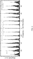
- FIG. 6 shows high-repetition-rate supercontinuum for a (panel A) spectrum of the 10-GHz EOM comb directly after generation.
- Panel B shows a ten-gigahertz supercontinuum spectra spanning from 750 to 2750 nm for two different silicon-nitride waveguide widths. The spectral intensity is scaled to intrawaveguide levels. Also shown is the spectrum of the first-stage highly nonlinear fiber (HNLF).
- Panel C shows a ten-gigahertz supercontinuum optimized for spectral smoothness by reducing incident power (blue). Between 830 and 1450 nm, a flat spectrum ( ⁇ 3 dB) is produced by a single passive optical attenuator.
- Panel D shows a supercontinuum spectrum from a 30-GHz EOM comb. Top insets show that comb coherence is maintained across the entire spectrum (optical SNRs are spectrometer limited). Bottom inset shows initial spectrum of the 30-GHz EOM comb. They axes in both (C) and (D) show the power spectral density (PSD) obtained in the output fiber.
- PSD power spectral density
- the chirped-pulse output of the EOM comb is compressible to durations as short as 600 fs, depending on the initial spectral bandwidth. Pulse durations greater than ⁇ 200 fs have been contemplated for coherent supercontinuum broadening in nonlinear media with anomalous dispersion. If the nonlinear material exhibits normal dispersion, broadening due to pure self-phase modulation is produces lower-noise spectra owing to the suppression of modulation instability.
- the ultrafast electro-optic laser includes two-stage broadening from a normal-dispersion highly nonlinear fiber (HNLF) to achieve initial spectral broadening and pulse compression to 100 fs followed by an anomalous-dispersion SiN waveguide for broad spectrum generation.
- HNLF normal-dispersion highly nonlinear fiber
- High-repetition rate lasers (f rep ⁇ 10 GHz) produce lower pulse energies for the same average power, making it challenging to use nonlinear broadening to produce the octave bandwidths required for self-referencing.
- patterned nanophotonic waveguides have high nonlinearity and engineerable dispersion.
- the ultrafast electro-optic laser has input-coupling efficiency with a SiN waveguide of up to 85% that enables a broadband supercontinuum to be generated with pulses from high-repetition rate ultrafast sources.
- the spectra generated with the 10-GHz EOM comb from the ultrafast electro-optic laser spans wavelengths from 750 nm to beyond 2700 nm for two different waveguide geometries ( FIG.
- the offset frequency is detected with >30 dB signal-to-noise ratio (SNR), suggesting that the scheme of combining normal- and anomalous-dispersion media indeed allows us to overcome the difficulties of producing a coherent supercontinuum using pulses longer than a few hundred femtoseconds; see FIG. 11 for SNR versus bandwidth.
- Stabilization of f 0 is subsequently accomplished by feeding back to the frequency-tuning port of the DRO.
- the feedback bandwidth is limited to ⁇ 200 kHz ( FIG. 7A ) and thus is insufficient on its own to narrow the comb linewidth set by the multiplied microwave noise of the DRO.
- FIG. 7 shows aspects of EOM-comb phase noise.
- Panel A shows optical phase noise of the comb offset frequency measured at 775 nm (left axis) and scaled to the 10-GHz repetition rate (right axis) under different locking conditions.
- Prestabilizing the free-running RF oscillator (DRO) using a high-Q microwave cavity in the stabilized-local-oscillator (STALO) configuration lowers the phase noise by up to 20 dB at frequencies below 500 kHz.
- DRO free-running RF oscillator
- STALO stabilized-local-oscillator
- the output of one high-power microwave amplifier is stabilized to an air-filled aluminum microwave cavity in the stabilized-local-oscillator (STALO) configuration and yields an immediate reduction in phase noise of up to 20 dB at frequencies less than 500 kHz from the carrier.
- STALO stabilized-local-oscillator
- the ⁇ -line distinguishes between regimes where the linewidth of the comb offset f 0 is adversely affected (phase noise above the ⁇ -line) and where there is no linewidth contribution (phase noise below the ⁇ -line). Having phase noise below the ⁇ -line at all points is approximately equivalent to an integrated phase noise below ⁇ radians and provides a convenient visual way to assess the impact of noise at different Fourier frequencies.
- the f 0 phase noise remains below the ⁇ -line at all frequencies only when both the STALO lock and the f-2f lock are used in tandem.
- the progression of offset-frequency stabilization is also shown by the beat frequencies as each lock is turned on ( FIG. 7 , panel B to D).
- the coherent carrier seen in the offset frequency when fully stabilized indicates that phase coherence has been achieved between individual comb lines across the entire available spectral bandwidth.
- the accuracy and precision of the stabilized EOM comb were determined by beating the 10-GHz repetition rate against the 40th harmonic of an independent mode-locked laser operating at 250 MHz. After 2000 s of averaging, a fractional stability of 3 ⁇ 10 ⁇ 17 was obtained with no statistically significant frequency offset observed. This level of accuracy represents an improvement of more than three orders of magnitude over previously demonstrated EOM-comb systems and is likely only limited here by averaging time and out-of-loop path differences between the two combs.
- pulses were made that had durations lasting a few cycles of the optical field. Pulses in this regime provide direct access to the carrier-envelope phase and high peak intensities but require a well-controlled output spectrum exhibiting a high degree of spectral flatness and coherence. However, achieving such pulses at gigahertz repetition rates with mode-locked lasers is technically challenging. Still, high-repetition rate sources of few-cycle pulses could be valuable for applications like optically controlled electronics, where both fast switching speeds and peak intensity are important.
- coherent Raman imaging of biological samples can benefit from transform-limited ultrashort pulses, but the acquisition speed for broadband spectra is typically restricted by the megahertz-rate mode-locked laser sources that are used. Extending to higher repetition rates could reduce measurement dead time and also prevent sample damage due to high peak powers.
- optical modulators to directly carve a train of ⁇ 1-ps pulses from a CW laser provides an effective method for generating clean few-cycle pulses thanks to the soliton self-compression effect.
- the pulse power and chirp incident on the SiN waveguide are adjusted such that the launched pulse approaches the threshold peak intensity for soliton fission near the output facet of the chip.
- a normal-dispersion single-element aspheric lens is then used to out-couple the light without introducing appreciable higher-order dispersion, and a 2-cm-long rod of fused silica glass recompresses the pulse to near its transform limit.
- FIG. 8 shows the reconstructed pulse profile obtained through frequency-resolved optical gating (FROG). Pulse durations of 15 fs (2.8 optical cycles, full width at half maximum) and out-coupled pulse energies in excess of 100 pJ (1 W average power) are readily achievable at a repetition rate of 10 GHz. With regard to FIG. 8 , few-cycle pulse generation are shown for (panel A) experimental and (panel B) reconstructed FROG traces. Panel C shows a reconstructed temporal pulse profile with a full width at half maximum duration of 15 fs (2.8 optical cycles). Panel D shows a comparison of reconstructed and experimental spectra.
- FROG frequency-resolved optical gating
- the quasi-CW spectral wings of the initial comb spectrum near 1550 nm do not contribute appreciably to the pulse and thus are not seen in the reconstructed spectrum. At least 75% of the total optical power is concentrated in the compressed pulse. More sophisticated amplitude and phase compensation of the initial comb spectrum could allow an even larger fraction of the power to be compressed.
- FIG. 9 shows frequency accuracy and stability for the ultrafast electro-optic laser.
- modified Allan deviation MDEV
- the top inset shows 11,000 s of frequency-counter data from which the MDEV curve was calculated (expected frequency subtracted), and the bottom inset shows a histogram of the data.
- the ultrafast electro-optic laser for production of 10-GHz EOM comb including both the optical and microwave stabilization components, is shown in FIG. 2
- a central mode of the EOM comb is formed from a 1550-nm CW laser that is stabilized with sub-hertz linewidth to an ultra-low expansion cavity.
- the comb can also be operated successfully with an external-cavity diode laser as the pump.
- the CW laser is then transmitted through two to four lithium-niobate phase modulators with low half-wave voltage (V ⁇ 3 V), optically connected in series, to produce a periodically chirped continuous waveform.
- the total number of modes generated by a single-phase modulator is determined by the microwave drive power and the modulator's half-wave voltage, though multiple modulators can be added in series with their microwave phases aligned to linearly increase the number of modes. In this case, at the highest drive power of 36 dBm, each modulator can make approximately 40 comb lines.
- An intensity modulator driven by the same microwave drive then carves the chirped output into a 50% duty-cycle pulse train that can be readily compressed to near the Fourier-transform limit using single-mode optical fiber, though a programmable pulse shaper is used here for ease of tunability. All components in the comb generator are polarization-maintaining for convenience and reliability.
- the comb output is then amplified with a single-mode erbium-doped fiber amplifier (EDFA, 25 dB gain, noise figure).
- EDFA single-mode erbium-doped fiber amplifier
- the optical filter cavity is a standard Fabry-Pérot filter with a free spectral range matched to the comb repetition rate and included two dielectric mirrors (99.9% reflectivity), each with a 1-m radius of curvature. No thermal, mechanical, or vacuum isolation is used.
- the rear surface of each mirror is antireflection coated and one mirror is glued to a piezoelectric transducer for length stabilization.
- Weak sidebands at 22 MHz are put on the comb by driving one of the comb's phase modulators in reverse via the RF output port. These sidebands are used to generate a Pound-Drever-Hall error signal for locking the cavity to the comb.
- the total fiber-to-fiber transmission of the cavity system is 75%.
- the aluminum microwave cavity used to pre-stabilize the 10-GHz DRO has a cylindrical geometry and is operated in the TE011 mode with an unloaded Qfactor of 8300.
- the cavity was machined in-house, though we note that comparable commercial options are available.
- the RF output port of one optical phase modulator is used to provide a power of up to 30 dBm for coupling to the STALO cavity.
- phase noise introduced by both the DRO and the amplifier can be suppressed.
- the cavity is operated in a nearly critically coupled regime in order to achieve the maximum carrier suppression (>30 dB) and frequency-discrimination sensitivity from the reflected signal.
- An error signal for locking the DRO to the cavity is generated by mixing this reflected signal with the original DRO output.
- Increasing the cavity Q or adding an additional low-phase-noise amplifier before the STALO mixer can improve the amount of phase-noise reduction that is achievable due to the enhanced sensitivity of the frequency-discrimination signal.
- the 10 GHz and 30 GHz pulse trains are amplified in an anomalous dispersion EDFA designed for sub-picosecond pulses (maximum output power 5 W, 45 dB gain, 5.8 dB noise figure) before undergoing two stages of nonlinear broadening.
- HNLF highly nonlinear fiber
- the HNLF has a free-space output facet that is angle-cleaved to prevent back reflections and the output beam is then directed to a pair of high-transmission diffraction gratings (940 grooves/mm) to compensate the HNLF dispersion.
- sub-100-fs pulses are delivered to the second-stage SiN waveguide with energies of approximately 150 pJ.
- the photonic waveguides used for the second-stage broadening were made with a photonic damascene process and low-pressure chemical-vapor-deposition (LPCVD) SiN, are 15 mm in length, and have a thickness of 750 nm.
- LPCVD low-pressure chemical-vapor-deposition
- a waveguide width of 1800 nm is chosen to produce a dispersive wave near the second harmonic (775 nm) of the pump laser (1550 nm), though the spectrum is adjustable by changing this parameter.
- the supercontinuum generation process is decoupled from the frequency doubling, resulting in very stable and reliable operation.
- the waveguides have a fully oxide-clad (SiO2) geometry that serves to both protect the waveguide from contamination as well as likely improving the ability of the device to withstand sustained thermal loads when incident with up to several watts of optical power.
- Input coupling to the waveguide is accomplished using a molded-glass aspheric lens with a design wavelength of 1550 nm and a numerical aperture (NA) of 0.6 while output-coupling is achieved with a 0.85-NA visible-wavelength microscope objective.
- spectral flattening of the waveguide output can be accomplished using a passive in-line fiber attenuator with a fixed 20-dB attenuation coefficient at 1550 nm. Due to an exponential roll-off in the attenuation coefficient in going to shorter wavelengths, a flatness of ⁇ 3 dB is achieved spanning from 850 nm to 1450 nm.
- a fiber-coupled waveguide PPLN is used for second-harmonic generation of residual 1550-nm pump light (100 mW) exiting the SiN waveguide for f-2f detection.
- the PPLN output is temporally and spatially overlapped with the 775-nm supercontinuum light, coupled to single mode fiber, and delivered to a 10-GHz-bandwidth photodetector with a built-in trans-impedance amplifier.
- the offset frequency of the comb must match the intrinsic offset frequency of the filter cavity in order to be transmitted efficiently.
- a beat frequency is detected near 3.5 GHz and is determined by the exact cavity geometry and mirror dispersion.
- the ⁇ 3 MHz cavity linewidth still supports a tuning range of a few-hundred megahertz for the offset while maintaining high transmission of the comb.
- this beat is electronically mixed down to 960 MHz before filtering and frequency division by 32.
- a phase-locked loop locks the resulting 30-MHz signal to an RF synthesizer by adjusting the voltage set point of the microwave cavity lock.
- An integrated version of the main feedback loop's output voltage is also used to provide a slow thermal correction to the microwave cavity through resistive heaters affixed to the outside.
- the phase noise of the comb is obtained via the photo detected offset frequency at 775 nm.
- the resulting curve is integrated to compute the RMS timing jitter of the electronic oscillator, and the optical pulse train that is directly derived from it. This integration (from 10 Hz to 4 MHz) yields a total jitter of 0.97 fs relative to the 1550-nm optical carrier for the fully locked 10 GHz comb.
- the spectra are obtained by stepping the frequency of a CW laser in 10 GHz increments and recording the down-mixed optical spectrum in the radio-frequency (RF) domain at each step. Bandwidths greater than 10 GHz are recorded by stitching together multiple acquisitions at each wavelength. Each individual 10 GHz span then contains a beat between the CW laser and the two nearest comb modes. Individual noise floor contributions from the CW laser and the comb are obtained at each wavelength by blocking the appropriate arm and recording a new trace.
- RF radio-frequency
- Comb lines closest to the 1550-nm pump wavelength exhibit the highest degree of contrast (nearly 60 dB at 1319 nm). However, even at the edge of the spectrum near 775 nm, more than 35 dB of contrast is obtained. In all cases the spectra exhibit very clean modes without any visible inter-mode artifacts or sidebands.
- FIG. 11 shows the offset-frequency beat notes as a function of EOM-comb bandwidth for the offset-frequency beat notes of the 10-GHz EOM comb as a function of the number of modes in the initial spectrum.
- Narrower-bandwidth comb spectra have reduced coherence after supercontinuum generation.
- the beat note pedestal results from residual microwave noise in the electronic oscillator and is a representation of the selected signal.
- the inset shows beat note SNR versus the number of initial comb lines, relative to the background noise floor.
- Each curve in the plot is obtained by symmetrically filtering the initial comb spectrum in increasing amounts using a programmable pulse shaper.
- the amplifier power is adjusted to maximize the achievable SNR of the beat.
- the SNR increases monotonically with the number of comb modes, indicating it is advantageous to maximize the microwave drive power and the number of phase modulators for best performance.
- FIG. 12A shows frequency counter data (gate time 1 s) of the in-loop comb offset frequency. No glitches are observed during the entire data set, indicating that neither temperature drifts nor beam-pointing fluctuations due to coupling watt-level powers to the SiN chip pose a significant obstacle for continuous operation.
- FIG. 12B shows reliable continuous operation, wherein panel A shows in-loop counter data for continuous glitch-free operation for more than 16 hrs (30 MHz set point subtracted). Panel B shows out-of-loop absolute frequency verification during acquisition (offset by expected value of 30.6 MHz). Time gaps in the data are due to the reference fiber comb losing phase lock.
- the absolute accuracy and stability of the comb is an important metric for comb performance.
- the frequency difference between repetition rates fdiff can then be counted with a frequency counter.
- the exact value of fdiff is defined solely in terms of the known RF-synthesizer set points and can be used to assess the absolute frequency synthesis accuracy of the comb without any data fitting or drift correction.
- FIG. 9 shows the measured stability of the difference in comb repetition rates after an acquisition time of 11,000 s.
- a zero-dead-time counter (H-type) is used to record the RF beat between the two 10 GHz signals while the MDEV is used for the stability calculations.
- H-type zero-dead-time counter
- the measured stability is limited by the counter and the ⁇ -3/2 slope is indicative of white phase noise for two mutually phase locked lasers.
- differential noise in the system frustrates the phase coherent averaging, though this noise could be reduced by path-length cancellation of the optical paths, allowing the same degree of stability to be reached at shorter averaging times.
- the MDEV yields a minimum uncertainty of 3.1 ⁇ 10 ⁇ 17 (310 nHz) for a carrier frequency of 10 GHz.
- the measured 163-nHz frequency offset in the mean of the acquisition is statistically consistent with zero synthesis error at the demonstrated level of stability.
- the demonstrated combination of operational reliability and absolute accuracy may make the EOM comb is a tool for long-term measurements of ultra-stable optical frequencies and optical clock networks.
- fa is the frequency-offset set point used to phase lock the auxiliary comb to the CW laser.
- a combination thereof refers to a combination comprising at least one of the named constituents, components, compounds, or elements, optionally together with one or more of the same class of constituents, components, compounds, or elements.
Landscapes
- Physics & Mathematics (AREA)
- Electromagnetism (AREA)
- Optics & Photonics (AREA)
- Engineering & Computer Science (AREA)
- Plasma & Fusion (AREA)
- Nonlinear Science (AREA)
- General Physics & Mathematics (AREA)
- Chemical & Material Sciences (AREA)
- Ceramic Engineering (AREA)
- Crystallography & Structural Chemistry (AREA)
- Optical Modulation, Optical Deflection, Nonlinear Optics, Optical Demodulation, Optical Logic Elements (AREA)
Abstract
Description
νp =f 0 +N frep
νp =f 0,aux αMf rep,aux −f a
where N and M are the mode numbers at the pump frequency for the EOM comb and auxiliary comb, respectively. fa is the frequency-offset set point used to phase lock the auxiliary comb to the CW laser.
Claims (20)
Priority Applications (1)
| Application Number | Priority Date | Filing Date | Title |
|---|---|---|---|
| US16/561,564 US11011882B2 (en) | 2018-09-05 | 2019-09-05 | Ultrafast electro-optic laser |
Applications Claiming Priority (2)
| Application Number | Priority Date | Filing Date | Title |
|---|---|---|---|
| US201862727289P | 2018-09-05 | 2018-09-05 | |
| US16/561,564 US11011882B2 (en) | 2018-09-05 | 2019-09-05 | Ultrafast electro-optic laser |
Publications (2)
| Publication Number | Publication Date |
|---|---|
| US20200076149A1 US20200076149A1 (en) | 2020-03-05 |
| US11011882B2 true US11011882B2 (en) | 2021-05-18 |
Family
ID=69640442
Family Applications (1)
| Application Number | Title | Priority Date | Filing Date |
|---|---|---|---|
| US16/561,564 Active 2039-10-30 US11011882B2 (en) | 2018-09-05 | 2019-09-05 | Ultrafast electro-optic laser |
Country Status (1)
| Country | Link |
|---|---|
| US (1) | US11011882B2 (en) |
Families Citing this family (15)
| Publication number | Priority date | Publication date | Assignee | Title |
|---|---|---|---|---|
| WO2018044500A1 (en) * | 2016-09-01 | 2018-03-08 | Imra America, Inc. | Ultra low noise photonic phase noise measurement system for microwave signal |
| EP3549210A4 (en) * | 2017-01-05 | 2020-07-29 | IPG Photonics Corporation | Optical frequency comb generator with carrier envelope offset frequency detection |
| US10756514B1 (en) * | 2019-07-02 | 2020-08-25 | The United States Of America As Represented By The Secretary Of The Army | Stabilizing a precision electro optical oscillator clock using an environmentally insensitive metamaterial device |
| US10951002B1 (en) * | 2019-12-04 | 2021-03-16 | Honeywell International Inc. | Bichromatic laser for quantum computing applications |
| US12266900B2 (en) * | 2019-12-20 | 2025-04-01 | Institute Of Science Tokyo | Light source device for fiber optic gyroscope and fiber optic gyroscope using the same |
| JP7334325B2 (en) * | 2020-02-21 | 2023-08-28 | 富士フイルム株式会社 | Imaging device |
| DE102020115338B3 (en) * | 2020-06-09 | 2021-11-18 | Toptica Photonics Ag | Optical scanning |
| CN112152066B (en) * | 2020-09-16 | 2021-09-10 | 飞秒激光研究中心(广州)有限公司 | Laser pulse energy amplification device and method and femtosecond laser |
| CN113451868B (en) * | 2021-05-28 | 2022-12-09 | 中国科学院西安光学精密机械研究所 | Compensation device and method for carrier envelope phase offset of ultrashort pulse laser |
| EP4394489A4 (en) * | 2021-08-25 | 2025-09-03 | Univ Electro Communications | WAVEFRONT CONTROL DEVICE AND ADAPTIVE OPTICAL DEVICE |
| CN114389136B (en) * | 2021-12-14 | 2023-08-29 | 中国科学院上海高等研究院 | A dual-phase detection laser phase-locking device and method |
| US12541701B2 (en) | 2022-01-14 | 2026-02-03 | California Institute Of Technology | Nanophotonic parametric quantum information processor |
| US20240061316A1 (en) * | 2022-08-11 | 2024-02-22 | California Institute Of Technology | Time-multiplexed photonic computer |
| WO2024224519A1 (en) * | 2023-04-26 | 2024-10-31 | 日本電信電話株式会社 | Optical frequency measuring device and measuring method |
| US12107380B1 (en) * | 2023-10-03 | 2024-10-01 | Vector Atomic, Inc. | Controlling soliton self-frequency shift |
Citations (8)
| Publication number | Priority date | Publication date | Assignee | Title |
|---|---|---|---|---|
| US20070229937A1 (en) * | 2006-03-31 | 2007-10-04 | Lothar Benedict Josef Moeller | Inexpensive terahertz wave generator |
| US20150029575A1 (en) * | 2012-03-14 | 2015-01-29 | Sumitomo Osaka Cement Co., Ltd. | Optical pulse-generator and optical pulse-generating method |
| US20150236784A1 (en) * | 2014-01-24 | 2015-08-20 | Kerry VAHALA | Stabilized microwave-frequency source |
| US20150372447A1 (en) * | 2014-06-19 | 2015-12-24 | Electronics And Telecommunications Research Institute | Apparatus and method for generating pulse laser |
| US20160254646A1 (en) * | 2015-02-26 | 2016-09-01 | California Institute Of Technology | Optical frequency divider based on an electro-optical-modulator frequency comb |
| US9653868B2 (en) | 2003-07-25 | 2017-05-16 | Imra America, Inc. | Pulsed laser sources |
| US10048567B2 (en) * | 2016-03-22 | 2018-08-14 | The United States Of America, As Represented By The Secretary Of Commerce | Electronic light synthesizer and process for electronically synthesizing light |
| US10585332B2 (en) * | 2018-03-06 | 2020-03-10 | University Of Central Florida Research Foundation, Inc. | Periodic optical filter stabilized tunable comb generator |
-
2019
- 2019-09-05 US US16/561,564 patent/US11011882B2/en active Active
Patent Citations (10)
| Publication number | Priority date | Publication date | Assignee | Title |
|---|---|---|---|---|
| US9653868B2 (en) | 2003-07-25 | 2017-05-16 | Imra America, Inc. | Pulsed laser sources |
| US20070229937A1 (en) * | 2006-03-31 | 2007-10-04 | Lothar Benedict Josef Moeller | Inexpensive terahertz wave generator |
| US20150029575A1 (en) * | 2012-03-14 | 2015-01-29 | Sumitomo Osaka Cement Co., Ltd. | Optical pulse-generator and optical pulse-generating method |
| US20150236784A1 (en) * | 2014-01-24 | 2015-08-20 | Kerry VAHALA | Stabilized microwave-frequency source |
| US20170012705A1 (en) * | 2014-01-24 | 2017-01-12 | California Institute Of Technology | Stabilized microwave-frequency source |
| US20150372447A1 (en) * | 2014-06-19 | 2015-12-24 | Electronics And Telecommunications Research Institute | Apparatus and method for generating pulse laser |
| US20160254646A1 (en) * | 2015-02-26 | 2016-09-01 | California Institute Of Technology | Optical frequency divider based on an electro-optical-modulator frequency comb |
| US9905999B2 (en) * | 2015-02-26 | 2018-02-27 | California Institute Of Technology | Optical frequency divider based on an electro-optical-modulator frequency comb |
| US10048567B2 (en) * | 2016-03-22 | 2018-08-14 | The United States Of America, As Represented By The Secretary Of Commerce | Electronic light synthesizer and process for electronically synthesizing light |
| US10585332B2 (en) * | 2018-03-06 | 2020-03-10 | University Of Central Florida Research Foundation, Inc. | Periodic optical filter stabilized tunable comb generator |
Non-Patent Citations (1)
| Title |
|---|
| David R. Carlson et al. "Ultrafast electro-optic light with subcycle control" Science 361, 1358-1363 Sep. 28, 2018 (Year: 2018). * |
Also Published As
| Publication number | Publication date |
|---|---|
| US20200076149A1 (en) | 2020-03-05 |
Similar Documents
| Publication | Publication Date | Title |
|---|---|---|
| US11011882B2 (en) | Ultrafast electro-optic laser | |
| Lucas et al. | Ultralow-noise photonic microwave synthesis using a soliton microcomb-based transfer oscillator | |
| US8170387B2 (en) | Laser based frequency standards and their applications | |
| Lilienfein et al. | Temporal solitons in free-space femtosecond enhancement cavities | |
| Endo et al. | Ultralow noise optical frequency combs | |
| US9252561B2 (en) | Frequency comb source with large comb spacing | |
| US10326251B2 (en) | Ultra-low noise mode-locked laser, methods, and applications | |
| US20170187161A1 (en) | Low carrier phase noise fiber oscillators | |
| Schimpf et al. | Frequency-comb-based laser system producing stable optical beat pulses with picosecond durations suitable for high-precision multi-cycle terahertz-wave generation and rapid detection | |
| Jang et al. | Comb-rooted multi-channel synthesis of ultra-narrow optical frequencies of few Hz linewidth | |
| Nardelli et al. | Optical and microwave metrology at the 10− 18 level with an Er/Yb: glass frequency comb | |
| EP4084238A1 (en) | Method and apparatus for controlling a pulse repetition rate of a pulsed laser beam, and pulsed laser oscillator with stabilized pulse repetition rate | |
| US10048567B2 (en) | Electronic light synthesizer and process for electronically synthesizing light | |
| Bunel et al. | Dual-frequency comb in fiber Fabry–Perot resonator | |
| Camenzind et al. | Ultra-low noise spectral broadening of two combs in a single ANDi fiber | |
| Pericherla | Semiconductor mode-locked lasers for applications in multi-photon imaging and microwave photonics | |
| Trask et al. | Self-oscillating, self-stabilizing, and self-referenced electro-optic comb | |
| Trask | Opto-Electronic Oscillator driven Electro-Optic Modulator based Optical Frequency Comb | |
| Laumer | Mid-IR frequency comb with sub-Hertz relative line width based on Raman soliton self-frequency shift | |
| Kippenberg | Platicon microcomb generation using laser self-injection locking | |
| JP2026020144A (en) | Universal Frequency Synthesizer | |
| Balskus | Versatile femtosecond optical parametric oscillator frequency combs for metrology | |
| Jornod | Semiconductor disk laser-based frequency combs | |
| Kuse et al. | Full stabilization of an electro-optic comb to a mode-locked fiber comb | |
| Del'Haye et al. | A chip-scale microwave repetition rate frequency comb |
Legal Events
| Date | Code | Title | Description |
|---|---|---|---|
| FEPP | Fee payment procedure |
Free format text: ENTITY STATUS SET TO UNDISCOUNTED (ORIGINAL EVENT CODE: BIG.); ENTITY STATUS OF PATENT OWNER: LARGE ENTITY |
|
| AS | Assignment |
Owner name: GOVERNMENT OF THE UNITED STATES OF AMERICA, AS REPRESENTED BY THE SECRETARY OF COMMERCE, MARYLAND Free format text: ASSIGNMENT OF ASSIGNORS INTEREST;ASSIGNORS:CARLSON, DAVID RICHARD;DIDDAMS, SCOTT ALAN;HICKSTEIN, DANIEL DURAND;AND OTHERS;SIGNING DATES FROM 20190912 TO 20191004;REEL/FRAME:050636/0231 |
|
| STPP | Information on status: patent application and granting procedure in general |
Free format text: NON FINAL ACTION MAILED |
|
| STPP | Information on status: patent application and granting procedure in general |
Free format text: NOTICE OF ALLOWANCE MAILED -- APPLICATION RECEIVED IN OFFICE OF PUBLICATIONS |
|
| STPP | Information on status: patent application and granting procedure in general |
Free format text: PUBLICATIONS -- ISSUE FEE PAYMENT RECEIVED |
|
| STPP | Information on status: patent application and granting procedure in general |
Free format text: PUBLICATIONS -- ISSUE FEE PAYMENT VERIFIED |
|
| STCF | Information on status: patent grant |
Free format text: PATENTED CASE |
|
| FEPP | Fee payment procedure |
Free format text: SURCHARGE FOR LATE PAYMENT, LARGE ENTITY (ORIGINAL EVENT CODE: M1554); ENTITY STATUS OF PATENT OWNER: LARGE ENTITY |
|
| MAFP | Maintenance fee payment |
Free format text: PAYMENT OF MAINTENANCE FEE, 4TH YEAR, LARGE ENTITY (ORIGINAL EVENT CODE: M1551); ENTITY STATUS OF PATENT OWNER: LARGE ENTITY Year of fee payment: 4 |