US11011857B2 - Wire termination using fixturing elements - Google Patents
Wire termination using fixturing elements Download PDFInfo
- Publication number
- US11011857B2 US11011857B2 US14/768,220 US201314768220A US11011857B2 US 11011857 B2 US11011857 B2 US 11011857B2 US 201314768220 A US201314768220 A US 201314768220A US 11011857 B2 US11011857 B2 US 11011857B2
- Authority
- US
- United States
- Prior art keywords
- coil
- wire
- pin
- connection
- fixturing
- Prior art date
- Legal status (The legal status is an assumption and is not a legal conclusion. Google has not performed a legal analysis and makes no representation as to the accuracy of the status listed.)
- Active, expires
Links
- 238000000034 method Methods 0.000 claims abstract description 29
- 238000003466 welding Methods 0.000 claims description 13
- 230000006835 compression Effects 0.000 claims description 7
- 238000007906 compression Methods 0.000 claims description 7
- BASFCYQUMIYNBI-UHFFFAOYSA-N platinum Chemical compound [Pt] BASFCYQUMIYNBI-UHFFFAOYSA-N 0.000 claims description 6
- 229910052751 metal Inorganic materials 0.000 claims description 3
- 239000002184 metal Substances 0.000 claims description 3
- 229910052697 platinum Inorganic materials 0.000 claims description 3
- 239000000463 material Substances 0.000 description 15
- 230000008901 benefit Effects 0.000 description 5
- 206010052428 Wound Diseases 0.000 description 4
- 238000010438 heat treatment Methods 0.000 description 4
- 230000008569 process Effects 0.000 description 4
- 238000005476 soldering Methods 0.000 description 4
- 239000007787 solid Substances 0.000 description 4
- 208000027418 Wounds and injury Diseases 0.000 description 3
- 238000005219 brazing Methods 0.000 description 3
- 230000013011 mating Effects 0.000 description 3
- HWLDNSXPUQTBOD-UHFFFAOYSA-N platinum-iridium alloy Chemical class [Ir].[Pt] HWLDNSXPUQTBOD-UHFFFAOYSA-N 0.000 description 3
- 229910000679 solder Inorganic materials 0.000 description 3
- 229910000566 Platinum-iridium alloy Inorganic materials 0.000 description 2
- 230000005611 electricity Effects 0.000 description 2
- 230000006870 function Effects 0.000 description 2
- PCHJSUWPFVWCPO-UHFFFAOYSA-N gold Chemical compound [Au] PCHJSUWPFVWCPO-UHFFFAOYSA-N 0.000 description 2
- 229910052737 gold Inorganic materials 0.000 description 2
- 239000010931 gold Substances 0.000 description 2
- 239000007943 implant Substances 0.000 description 2
- 239000000155 melt Substances 0.000 description 2
- 229910052709 silver Inorganic materials 0.000 description 2
- 239000004332 silver Substances 0.000 description 2
- 239000004593 Epoxy Substances 0.000 description 1
- ATJFFYVFTNAWJD-UHFFFAOYSA-N Tin Chemical compound [Sn] ATJFFYVFTNAWJD-UHFFFAOYSA-N 0.000 description 1
- RTAQQCXQSZGOHL-UHFFFAOYSA-N Titanium Chemical compound [Ti] RTAQQCXQSZGOHL-UHFFFAOYSA-N 0.000 description 1
- 230000009471 action Effects 0.000 description 1
- 230000002411 adverse Effects 0.000 description 1
- 229910045601 alloy Inorganic materials 0.000 description 1
- 239000000956 alloy Substances 0.000 description 1
- 238000005452 bending Methods 0.000 description 1
- 230000015572 biosynthetic process Effects 0.000 description 1
- 239000004020 conductor Substances 0.000 description 1
- 235000019589 hardness Nutrition 0.000 description 1
- 238000007689 inspection Methods 0.000 description 1
- 238000009413 insulation Methods 0.000 description 1
- 229910052741 iridium Inorganic materials 0.000 description 1
- GKOZUEZYRPOHIO-UHFFFAOYSA-N iridium atom Chemical compound [Ir] GKOZUEZYRPOHIO-UHFFFAOYSA-N 0.000 description 1
- 230000001788 irregular Effects 0.000 description 1
- 238000005304 joining Methods 0.000 description 1
- 230000007774 longterm Effects 0.000 description 1
- 238000005259 measurement Methods 0.000 description 1
- 238000002844 melting Methods 0.000 description 1
- 230000008018 melting Effects 0.000 description 1
- 229910001092 metal group alloy Inorganic materials 0.000 description 1
- 238000012986 modification Methods 0.000 description 1
- 230000004048 modification Effects 0.000 description 1
- 230000003287 optical effect Effects 0.000 description 1
- 238000012856 packing Methods 0.000 description 1
- 238000003825 pressing Methods 0.000 description 1
- 239000010935 stainless steel Substances 0.000 description 1
- 229910001220 stainless steel Inorganic materials 0.000 description 1
- 238000012360 testing method Methods 0.000 description 1
- 239000010936 titanium Substances 0.000 description 1
- 229910052719 titanium Inorganic materials 0.000 description 1
Images


Classifications
-
- H—ELECTRICITY
- H01—ELECTRIC ELEMENTS
- H01R—ELECTRICALLY-CONDUCTIVE CONNECTIONS; STRUCTURAL ASSOCIATIONS OF A PLURALITY OF MUTUALLY-INSULATED ELECTRICAL CONNECTING ELEMENTS; COUPLING DEVICES; CURRENT COLLECTORS
- H01R4/00—Electrically-conductive connections between two or more conductive members in direct contact, i.e. touching one another; Means for effecting or maintaining such contact; Electrically-conductive connections having two or more spaced connecting locations for conductors and using contact members penetrating insulation
- H01R4/02—Soldered or welded connections
- H01R4/023—Soldered or welded connections between cables or wires and terminals
-
- H—ELECTRICITY
- H01—ELECTRIC ELEMENTS
- H01R—ELECTRICALLY-CONDUCTIVE CONNECTIONS; STRUCTURAL ASSOCIATIONS OF A PLURALITY OF MUTUALLY-INSULATED ELECTRICAL CONNECTING ELEMENTS; COUPLING DEVICES; CURRENT COLLECTORS
- H01R4/00—Electrically-conductive connections between two or more conductive members in direct contact, i.e. touching one another; Means for effecting or maintaining such contact; Electrically-conductive connections having two or more spaced connecting locations for conductors and using contact members penetrating insulation
- H01R4/02—Soldered or welded connections
- H01R4/027—Soldered or welded connections comprising means for positioning or holding the parts to be soldered or welded
-
- H—ELECTRICITY
- H01—ELECTRIC ELEMENTS
- H01R—ELECTRICALLY-CONDUCTIVE CONNECTIONS; STRUCTURAL ASSOCIATIONS OF A PLURALITY OF MUTUALLY-INSULATED ELECTRICAL CONNECTING ELEMENTS; COUPLING DEVICES; CURRENT COLLECTORS
- H01R4/00—Electrically-conductive connections between two or more conductive members in direct contact, i.e. touching one another; Means for effecting or maintaining such contact; Electrically-conductive connections having two or more spaced connecting locations for conductors and using contact members penetrating insulation
- H01R4/10—Electrically-conductive connections between two or more conductive members in direct contact, i.e. touching one another; Means for effecting or maintaining such contact; Electrically-conductive connections having two or more spaced connecting locations for conductors and using contact members penetrating insulation effected solely by twisting, wrapping, bending, crimping, or other permanent deformation
- H01R4/12—Electrically-conductive connections between two or more conductive members in direct contact, i.e. touching one another; Means for effecting or maintaining such contact; Electrically-conductive connections having two or more spaced connecting locations for conductors and using contact members penetrating insulation effected solely by twisting, wrapping, bending, crimping, or other permanent deformation by twisting
-
- H—ELECTRICITY
- H01—ELECTRIC ELEMENTS
- H01R—ELECTRICALLY-CONDUCTIVE CONNECTIONS; STRUCTURAL ASSOCIATIONS OF A PLURALITY OF MUTUALLY-INSULATED ELECTRICAL CONNECTING ELEMENTS; COUPLING DEVICES; CURRENT COLLECTORS
- H01R4/00—Electrically-conductive connections between two or more conductive members in direct contact, i.e. touching one another; Means for effecting or maintaining such contact; Electrically-conductive connections having two or more spaced connecting locations for conductors and using contact members penetrating insulation
- H01R4/10—Electrically-conductive connections between two or more conductive members in direct contact, i.e. touching one another; Means for effecting or maintaining such contact; Electrically-conductive connections having two or more spaced connecting locations for conductors and using contact members penetrating insulation effected solely by twisting, wrapping, bending, crimping, or other permanent deformation
- H01R4/16—Electrically-conductive connections between two or more conductive members in direct contact, i.e. touching one another; Means for effecting or maintaining such contact; Electrically-conductive connections having two or more spaced connecting locations for conductors and using contact members penetrating insulation effected solely by twisting, wrapping, bending, crimping, or other permanent deformation by bending
-
- H—ELECTRICITY
- H01—ELECTRIC ELEMENTS
- H01R—ELECTRICALLY-CONDUCTIVE CONNECTIONS; STRUCTURAL ASSOCIATIONS OF A PLURALITY OF MUTUALLY-INSULATED ELECTRICAL CONNECTING ELEMENTS; COUPLING DEVICES; CURRENT COLLECTORS
- H01R4/00—Electrically-conductive connections between two or more conductive members in direct contact, i.e. touching one another; Means for effecting or maintaining such contact; Electrically-conductive connections having two or more spaced connecting locations for conductors and using contact members penetrating insulation
- H01R4/28—Clamped connections, spring connections
- H01R4/48—Clamped connections, spring connections utilising a spring, clip, or other resilient member
- H01R4/4854—Clamped connections, spring connections utilising a spring, clip, or other resilient member using a wire spring
- H01R4/4863—Coil spring
- H01R4/4872—Coil spring axially compressed to retain wire end
-
- H—ELECTRICITY
- H01—ELECTRIC ELEMENTS
- H01R—ELECTRICALLY-CONDUCTIVE CONNECTIONS; STRUCTURAL ASSOCIATIONS OF A PLURALITY OF MUTUALLY-INSULATED ELECTRICAL CONNECTING ELEMENTS; COUPLING DEVICES; CURRENT COLLECTORS
- H01R43/00—Apparatus or processes specially adapted for manufacturing, assembling, maintaining, or repairing of line connectors or current collectors or for joining electric conductors
- H01R43/02—Apparatus or processes specially adapted for manufacturing, assembling, maintaining, or repairing of line connectors or current collectors or for joining electric conductors for soldered or welded connections
- H01R43/0214—Resistance welding
-
- H—ELECTRICITY
- H01—ELECTRIC ELEMENTS
- H01R—ELECTRICALLY-CONDUCTIVE CONNECTIONS; STRUCTURAL ASSOCIATIONS OF A PLURALITY OF MUTUALLY-INSULATED ELECTRICAL CONNECTING ELEMENTS; COUPLING DEVICES; CURRENT COLLECTORS
- H01R43/00—Apparatus or processes specially adapted for manufacturing, assembling, maintaining, or repairing of line connectors or current collectors or for joining electric conductors
- H01R43/02—Apparatus or processes specially adapted for manufacturing, assembling, maintaining, or repairing of line connectors or current collectors or for joining electric conductors for soldered or welded connections
- H01R43/0221—Laser welding
-
- H—ELECTRICITY
- H01—ELECTRIC ELEMENTS
- H01R—ELECTRICALLY-CONDUCTIVE CONNECTIONS; STRUCTURAL ASSOCIATIONS OF A PLURALITY OF MUTUALLY-INSULATED ELECTRICAL CONNECTING ELEMENTS; COUPLING DEVICES; CURRENT COLLECTORS
- H01R43/00—Apparatus or processes specially adapted for manufacturing, assembling, maintaining, or repairing of line connectors or current collectors or for joining electric conductors
- H01R43/02—Apparatus or processes specially adapted for manufacturing, assembling, maintaining, or repairing of line connectors or current collectors or for joining electric conductors for soldered or welded connections
- H01R43/0235—Apparatus or processes specially adapted for manufacturing, assembling, maintaining, or repairing of line connectors or current collectors or for joining electric conductors for soldered or welded connections for applying solder
-
- H—ELECTRICITY
- H01—ELECTRIC ELEMENTS
- H01R—ELECTRICALLY-CONDUCTIVE CONNECTIONS; STRUCTURAL ASSOCIATIONS OF A PLURALITY OF MUTUALLY-INSULATED ELECTRICAL CONNECTING ELEMENTS; COUPLING DEVICES; CURRENT COLLECTORS
- H01R43/00—Apparatus or processes specially adapted for manufacturing, assembling, maintaining, or repairing of line connectors or current collectors or for joining electric conductors
- H01R43/02—Apparatus or processes specially adapted for manufacturing, assembling, maintaining, or repairing of line connectors or current collectors or for joining electric conductors for soldered or welded connections
- H01R43/0263—Apparatus or processes specially adapted for manufacturing, assembling, maintaining, or repairing of line connectors or current collectors or for joining electric conductors for soldered or welded connections for positioning or holding parts during soldering or welding process
-
- H—ELECTRICITY
- H01—ELECTRIC ELEMENTS
- H01R—ELECTRICALLY-CONDUCTIVE CONNECTIONS; STRUCTURAL ASSOCIATIONS OF A PLURALITY OF MUTUALLY-INSULATED ELECTRICAL CONNECTING ELEMENTS; COUPLING DEVICES; CURRENT COLLECTORS
- H01R2201/00—Connectors or connections adapted for particular applications
- H01R2201/12—Connectors or connections adapted for particular applications for medicine and surgery
Definitions
- Wires and cables are electrically and/or mechanically connected to a variety of different anchor points.
- a signal wire may be electrically and mechanically connected to a pin.
- the pin provides a mechanical anchor that resists mechanical forces applied to the wire.
- the pin may also serve as an electrical conductor between the wire and other electrical components.
- FIGS. 1A-1G show a coil that can be used to secure a wire in place near or around a pin, according to one example of principles described herein.
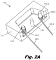
- FIG. 2A is a perspective view showing coils securing wires to pins, according to one example of principles described herein.
- FIG. 2B is a perspective view of a coil securing a wire in place around a pin, according to one example of principles described herein.
- FIGS. 3A-3B are side views of steps in a method for making a connection between a wire and a pin using a coil, according to one example of principles described herein.
- FIGS. 4A-4H show various fixturing elements being used to hold a wire around a pin, according to one example of principles described herein.
- FIG. 5 is a flowchart of a method for securing a wire to a pin using a coil, according to one example of principles described herein.
- Implanted medical devices are typically minimum sized and use materials that are biocompatible with the implanted environment. Due to their small size and materials, implanted medical devices can require high precision parts, significant assembly time, custom fixturing, and specialized connection techniques. For example, making an electrical connection between a wire and a pin in an implanted medical device can be time consuming and expensive. Many standard wire connection techniques are not useful because of the small size or material constraints. For example, soldering may not be practicable because standard soldering materials (lead, tin, silver, etc) are not biocompatible. Further, because of the small size of the wire and anchor point (such as a pin), custom fixturing is typically used to hold the wire in place over the anchor point while the connection is made. The cost for these unique parts and the steps needed to assemble and connect them adds expense and process time.
- connection systems and methods described below relate to a coil or other fixturing element that slides over a pin.
- This fixturing element allows a wire to be easy placed around or near the coil and temporarily holds the wire in place until a permanent connection between the wire and the pin can be formed.
- the fixturing element becomes part of the permanent connection.
- the fixturing element serves multiple purposes: it is a simple inexpensive temporary fixturing to position the connection for welding, soldering, and brazing and provides permanent additional material for the melt and overall structure. This may be particularly useful when welding a very small diameter wire or cable.
- the wire or braided cable is pulled tight between the turns of the coil and captured when the coil is collapsed.
- a resistance welder fitted with an electrode having a hole in the center goes over the pin while applying pressure to the end of the coil.
- the welding process fuses the parts together.
- the result is a self-fixtured welded assembly that does not require expensive tooling. This process does not require precise or highly toleranced mating parts.
- the coil, as a part of the assembly compensates for dimensional variation in the mating components. As a result, the mating components can be fabricated using less stringent tolerances and at a lower cost. Further, the coil couples multiple components together without elaborate fixturing or touch time.
- FIGS. 1A-1G show various examples of fixturing elements that have a coil configuration.
- the fixturing elements may be formed from a variety of materials and have different properties.
- FIG. 1A shows a compression coil ( 100 ) in its relaxed normally-open configuration. hi this example the coil is a helically wound, multi-turn cylindrical coil. The coil is placed over the pin and the wire is wrapped between the coils.
- FIG. 1B shows the same coil ( 100 ) in a compressed configuration with a compression force acting on it, shown by arrows. In its compressed configuration, the coil captures the wire or cable that is in between the coils.
- FIGS. 1C and 1D show an extension spring coil designed to resist extension of the spring.
- FIG. 1C shows the extension spring coil ( 100 ) in its extended configuration, being acted on by an extension force shown by arrows.
- FIG. 1D shows the extension spring coil ( 100 ) in its relaxed compressed configuration.
- the coil ( 100 ) is extended, as in FIG. 10 , a wire is inserted between the turns of the coil. The coil ( 100 ) is then allowed to relax ( FIG. 1D ) to sandwich the wire between adjacent turns.
- the coil ( 100 ) may be formed from a plastic material or metal that does not exhibit significant resilience.
- the coil ( 100 ) may be open wound or may be close wound and then stretched to an open configuration as shown in FIG. 1E .
- FIG. 1F shows a compressive force acting on the non resilient coil ( 100 ) to compress it into a closed configuration.
- FIG. 1G shows the coil ( 100 ) remaining in the closed configuration after the compressive force is removed.
- in the open configuration there are significant gaps between adjacent turns of the coil.
- the height of the coil in the open configuration is significantly greater than in the closed configuration. As described below, the closed configuration holds the wire in place around the pin.
- the coils described above are designed to secure a wire around a cylindrical pin.
- the coil could have a variety of different configurations to perform its function.
- the coil could also be rectangular.
- the coil may have any number of turns.
- the turns may have a variety of diameters including different diameters within a single coil.
- the coil may be formed from a variety of materials and material conditions.
- FIG. 2A shows a terminal ( 110 ) that includes a base ( 111 ) with three pins ( 115 ).
- a coil ( 100 - 1 ) has been placed, in its open configuration, over a first pin ( 115 - 1 ) and a cable or wire ( 120 - 1 ) has been wrapped partially around the pin ( 115 - 1 ) and between the turns of the open coil ( 100 - 1 ).
- Another coil ( 100 - 2 ) is shown in its closed configuration after placing it over a second pin ( 115 - 2 ) with cable or wire ( 120 - 2 ) captured between turns of coil.
- the coil ( 100 - 2 ) secures the cable or wire ( 120 - 2 ) near the pin ( 115 - 2 ) for making a more permanent connection.
- coil 100 - 2 is a compression spring
- force is applied to continue to compress the spring, such as using a resistance welding electrode (see, e.g., FIG. 3B ).
- the wire or cable may be wrapped around the pin or may be inserted between the coils while remaining straight.
- the coils ( 100 ) could be formed from any of a number of materials depending on the application.
- the coil could be formed from braze materials, silver, gold, or other materials.
- the coil may be formed from materials with a high level of biological compatibility, such as platinum, iridium, gold, or alloys thereof.
- the coil and wire may be formed from platinum iridium alloys.
- the physical characteristics of the coil may be altered using a number of techniques, including heat treating.
- the coil may be formed from platinum or a platinum iridium alloy and may have a range of hardnesses including an annealed dead soft state. This allows the coil to be compressed, capturing the wire or cable without any significant tendency to spring back into its previous shape.
- the pin, coil, and wire or cable may be the same or different materials.
- FIG. 2B is a perspective view of a coil ( 100 - 2 ) securing a wire ( 120 - 2 ) in place around a pin ( 115 - 2 ).
- the pin has a diameter of approximately 700 to 800 microns and the multi-strand wire used to form the coil has a diameter of approximately 50 to 150 microns.
- Each strand in the multi-strand wire has a diameter of about 10 to 30 microns.
- the strands may be wound or woven to form the mufti-strand wire.
- the multi-strand wire may be formed from a platinum iridium alloy and can be coated with an insulating cover. Prior to connection to the pin, the insulating cover may be removed to allow full mechanical and electrical contact between the wire, coil, and pin.
- FIG. 2B shows a close up of the coil ( 100 - 2 ) and wire ( 120 - 2 ) welded to the pin ( 115 - 2 ) using a resistance welder (see, e.g., FIG. 3B ).
- the resistance welder in this example produced only minimal distortion of the coil and wire. Higher currents and/or voltages may produce a welded joint with more melting.
- FIGS. 2A and 2B are only one example. A variety of other configurations, geometries, and materials could be used. For example, instead of multi-strand wire, a solid wire could be used. Further, the wire may be wrapped any practicable number of times around the pin.
- FIGS. 3A-3B are side views showing steps in a method for making a connection between a wire ( 120 ) and a pin ( 115 ) using a coil ( 100 ).
- a cross section of a solid wire ( 120 ) is shown.
- the coil ( 100 ) includes approximately 4 to 5 turns and fits over the pin ( 115 ).
- the pin ( 115 ) is secured to a base ( 111 ).
- FIG. 3A shows the coil ( 100 ) compressed over the solid wire ( 120 ). After the wire ( 120 ) is secured to the pin ( 115 ), a more permanent connection can be formed between the wire ( 120 ) and the pin ( 115 ) using a variety of different techniques.
- soldering, brazing, reflowing, laser welding, and resistance welding could be used to permanently join the wire ( 120 ) to the pin ( 115 ).
- the coil ( 100 ) holds the wire ( 120 ) in the desired position during formation of the permanent connection. Additionally, the coil ( 100 ) may form part of the permanent connection. For example, in a resistance weld, the coil is welded to the pin and to the wire, completing the electrical circuit from the pin to the wire. For brazing operations, the surfaces of coil may create additional capillary action that encourages braze flow into and around joint.
- FIG. 3B shows a permanent connection being formed using a resistance welder.
- a cross section of the resistance welding electrode ( 125 ) is shown.
- the electrode ( 125 ) has a cylindrical shape with an inner diameter that is sized to pass over the outer diameter of the pin ( 115 ).
- the electrode ( 125 ) may be “U” shaped or have another geometry that fits around/over the pin ( 115 ).
- the electrode ( 125 ) is placed over the pin ( 115 ) and compresses the coil ( 100 ). A surge of electricity is then applied by the electrode ( 125 ) to the coil ( 100 ), pin ( 115 ) and wire ( 120 ).
- FIG. 3B shows a voltage V applied to the resistance welding electrode ( 125 ).
- the conducting base ( 111 ) is grounded so that a current (shown by the dashed arrows) passes through the coil ( 100 ), pin ( 115 ), wire ( 120 ) and into the base ( 111 ).
- the electricity causes resistance heating that melts the coil ( 100 ) to the wire ( 120 ) and pin ( 115 ).
- the base ( 111 ) in this example is a structural conductive metal such as stainless steel or titanium. Because of the large cross section of the base ( 111 ) there is minimal resistive heating in the bulk of the base ( 111 ). The principle heating occurs in proximity to the pin ( 115 ), wire ( 120 ) and coil ( 100 ). After the weld is complete the electrode ( 125 ) is then removed.
- connection can then be tested using optical inspection, making electrical resistance measurements, or performing structural tests.
- the pin may not be conductive.
- the wire may serve a structural or electrical function but the pin is plastic and is intended as a strain relief anchor.
- the coil can be placed around the plastic pin and hold the wire in place while the pin is heat staked. Heat staking the pin causes the plastic that makes up the pin to melt and flow around/through the coil and wire, forming a fixed structural connection.
- FIGS. 4A-4D are views of various alternative methods for using a coil ( 100 ) for wire termination and fixturing.
- the pin ( 115 ) extends upward from a base ( 111 ).
- the pin ( 115 ) and base ( 111 ) could have any of a variety of geometries and configurations.
- FIG. 4A shows a wire ( 120 ) placed between a coil ( 100 ) and a pin ( 115 ). The wire ( 120 ) enters the coil ( 100 ) from the top and terminates after exiting the bottom coil ( 100 ).
- FIG. 4B shows a stranded wire ( 121 ) entering from the opposite direction.
- the wire ( 120 ) enters the coil ( 100 ) from the bottom and terminates as it exits the top of the coil ( 100 ).
- the wires that are fixtured using a coil may be stranded, braided, or solid and may have a variety of cross sectional geometries including circular, elliptical, flat, rectangular, irregular, or other geometry.
- FIGS. 4C and 4D show a coil ( 130 ) that is made from a spiral of wire with a rectangular cross section.
- FIG. 4C shows a perspective view of the pin ( 115 ) extending upward from the base ( 111 ), with the coil ( 130 ) formed from wire with a rectangular cross section.
- FIG. 4D shows a cross section of the coil ( 130 ) and pin ( 115 ) with a stranded wire ( 135 ) wrapped around the pin ( 115 ) and between the coils ( 130 ).
- This implementation may have a number of advantages including better packing between coils ( 130 ) and more effective gripping of the wire ( 135 ).
- FIG. 4E shows a stranded wire ( 135 ) that loops around the pin ( 115 ) and is compressed between two Belleville washers ( 140 ).
- Belleville washers are a disk spring with a frusto-conical shape. Belleville washers are characterized by high spring constants over a limited compression distance.
- a first Belleville washer ( 140 - 1 ) is placed over the pin ( 115 ).
- the wire ( 135 ) is wrapped around the pin ( 115 ) and a second Belleville washer ( 140 - 2 ) is placed over the wire ( 135 ).
- FIG. 4F shows a perspective view of this connection, with the stranded wire ( 135 ) wrapping clockwise around the pin ( 115 ).
- the wire is sandwiched between the upper surface of a first Belleville washer ( 140 - 1 ) and the lower surface of the second Belleville washer ( 140 - 2 ).
- a variety of other washer types could be used, including flat washers, split washers, wave washers, serrated washers, or geometries.
- FIG. 4G is a side view of multiple wires ( 120 - 1 , 120 - 2 ) that are fixtured by a coil.
- the wires ( 120 ) pass up through a coil ( 100 ).
- the coil can fixture a number of wires and allow an electrical connection to be made between the wires and the post ( 115 ).
- connections between wires may be easily and conveniently formed at an anchor point (the pin 115 ).
- the anchor point prevents tension or thermal heating in one wire from adversely affecting the other wire(s).
- Any of the coils and fixturing techniques described herein can be adapted to hold multiple wires.
- One of the advantages of using a coil is that the same fixturing technique can be used to secure one wire, two wires, three wires or more than three wires.
- FIG. 4H is a top view of a pin ( 115 ) that extends upward from a base ( 111 ).
- a number of wires ( 120 ) are placed tangent to the pin ( 115 ).
- the wires may be under a coil ( 100 ) or between turns of the coil ( 100 ).
- the outer perimeter of the coil ( 100 ) is shown as a dashed line.
- the coil ( 100 ) then holds the wires in place while a permanent connection is made.
- This configuration has a number of advantages. For example, there is no need to form the wires ( 120 ) into a hook shape or wrap the wires around the pin ( 115 ).
- the insulation (if any) can be stripped off the wires and the wires can be place tangent to the pin ( 115 ).
- this technique reduces the chances of fracturing the wire during the bending and reduces the cost of making the connection.
- the coil and/or wires may be specially adapted to securely fixture the wires where there is a smaller surface contact area between the wire and the coil.
- the coil may exert greater compressive forces to more firmly grip the smaller surface area of the wire in contact with the coil.
- the coil or wire may have flat surfaces to increase the contact area. This configuration is also well adapted to connecting larger numbers of wires together.
- FIG. 5 is a flowchart of one illustrative method ( 500 ) for securing a wire around a connection pin using a fixturing element.
- the fixturing element may be any of a variety of devices, including coils, springs, washers, or other elements that fit over the connection pin.
- the fixturing element is placed over the connection pin (step 505 ).
- the fixturing element may be a coil.
- the inside diameter of the coil may be larger, smaller or the same as the outside diameter of the pin. Where a very snug fit is desired, the inside diameter of the coil may be significantly smaller that the outside diameter of the pin. When the coil is forced over the pin, the coil expands and may slightly uncoil.
- the wire is captured between an upper surface and a lower surface of the fixturing element (step 510 ).
- the upper surface may be an upper turn of a coil and the lower surface may be lower turn of the coil.
- the upper surface of a first washer and the lower surface may be a second washer.
- the wire may remain straight, lying tangent to the pin.
- the wire may make a partial wind around the pin as shown in FIG. 2 or the wire may make one, two or more complete revolutions around the pin.
- the fixturing element is compressed to hold the wire around the pin (step 515 ).
- positive pressure may be used to keep the fixturing element compressed.
- the spring itself may provide the compression force.
- the coil may be dead soft so that it deforms when pressure is applied and remains deformed after the pressure is removed.
- a fixed electrical/mechanical connection can then be made between the wire and the pin (step 520 ).
- the fixed connection is a stable connection that bonds the wire to the pin.
- the fixed connection may be a weld joint, a solder joint, a braze joint, epoxy joint, or other connection.
- the fixed connection may or may not be permanent.
- a solder joint is not necessarily a permanent connection because the solder could be melted and the wire withdrawn from the connection.
- a welded connection is typically viewed as a permanent connection because the wire typically cannot be removed without damage to the pin or wire.
- the coil holds the wire in place during the creation of the fixed connection. For example, if the assembly needs to be moved to a different station to form the fixed connection, the coil holds the wire around the pin during the motion.
- the permanent electrical/mechanical connection can be formed in a variety of ways including the use of laser or resistance welding.
- the coil may be intentionally formed with an inner diameter that is smaller than the outer diameter of the pin. When placed over the pin the coil will adapt to the size of the pin by expanding and/or slightly uncoiling. The coils then grips the pin. The wire can be forced in between the coils or in between the pin and the wires. In some examples, the coil may be placed over the wire, the wire placed near the pin and then the coil slid down the wire and over the pin and the wire.
- the coil can readily adapt to different sized pin and wires, the tolerances of the pins and coils can be greater while still allowing a range of wire types (including dissimilar metal alloys) and diameters to be connected. This makes the connection less expensive to fabricate. Using a coil to “couple” multiple components together does not require elaborate fixturing or touch time to load into custom fixtures.
Landscapes
- Engineering & Computer Science (AREA)
- Manufacturing & Machinery (AREA)
- Physics & Mathematics (AREA)
- Optics & Photonics (AREA)
- Connections Effected By Soldering, Adhesion, Or Permanent Deformation (AREA)
Abstract
Description
Claims (6)
Applications Claiming Priority (1)
| Application Number | Priority Date | Filing Date | Title |
|---|---|---|---|
| PCT/US2013/026858 WO2014130022A1 (en) | 2013-02-20 | 2013-02-20 | Wire termination using fixturing elements |
Publications (2)
| Publication Number | Publication Date |
|---|---|
| US20150380833A1 US20150380833A1 (en) | 2015-12-31 |
| US11011857B2 true US11011857B2 (en) | 2021-05-18 |
Family
ID=47827462
Family Applications (1)
| Application Number | Title | Priority Date | Filing Date |
|---|---|---|---|
| US14/768,220 Active 2035-03-29 US11011857B2 (en) | 2013-02-20 | 2013-02-20 | Wire termination using fixturing elements |
Country Status (4)
| Country | Link |
|---|---|
| US (1) | US11011857B2 (en) |
| EP (1) | EP2959544B1 (en) |
| CN (1) | CN105122547B (en) |
| WO (1) | WO2014130022A1 (en) |
Families Citing this family (1)
| Publication number | Priority date | Publication date | Assignee | Title |
|---|---|---|---|---|
| US20200009393A1 (en) * | 2018-07-03 | 2020-01-09 | Advanced Bionics Ag | Antenna Wire Termination Assemblies for Use in Implantable Medical Devices |
Citations (32)
| Publication number | Priority date | Publication date | Assignee | Title |
|---|---|---|---|---|
| US2078825A (en) * | 1935-08-10 | 1937-04-27 | Josiah B Wisner | Connecter device |
| US3066274A (en) | 1960-06-03 | 1962-11-27 | Bell Telephone Labor Inc | Connection of insulated wire |
| US3145068A (en) * | 1962-10-09 | 1964-08-18 | Herbert S Neale | Wire connector |
| US3150911A (en) * | 1961-06-22 | 1964-09-29 | Cosmic Voice Inc | Binding post |
| US3171705A (en) * | 1962-04-25 | 1965-03-02 | Siemon Co | Coil-type electrical connector |
| US3284759A (en) * | 1964-05-25 | 1966-11-08 | Stephen N Buchanan | Electrical connector and connection made therewith |
| US3639978A (en) * | 1969-11-03 | 1972-02-08 | Atomic Energy Commission | Method for making flexible electrical connections |
| US3657651A (en) * | 1969-06-02 | 1972-04-18 | Duncan Electric Co Inc | One piece meter current circuit |
| US4080604A (en) * | 1976-09-21 | 1978-03-21 | Robyn International, Inc. | Means for tuning a loaded coil antenna |
| US4149767A (en) * | 1978-04-03 | 1979-04-17 | Northern Telecom Limited | Self-shearing connector for electrical conductors |
| US4334208A (en) * | 1979-10-16 | 1982-06-08 | U.S. Philips Corporation | Coil former for a transformer |
| US4706744A (en) * | 1986-08-22 | 1987-11-17 | Atlantic Richfield Company | Wireline tool connector |
| US5020214A (en) * | 1987-09-30 | 1991-06-04 | Hitachi, Ltd. | Method of manufacturing a hot wire air flow meter |
| GB2263202A (en) | 1991-08-07 | 1993-07-14 | Ranton & Co Ltd | Coil-spring contact for lampholder |
| CN2178947Y (en) | 1993-09-21 | 1994-10-05 | 陈新国 | Wiring terminal |
| JPH0729671A (en) | 1993-07-10 | 1995-01-31 | Kawai Denki Seisakusho:Kk | Sheathed heater |
| US5476398A (en) * | 1993-09-21 | 1995-12-19 | Matra Marconi Space France | Pluggable electrical connection device |
| US5497936A (en) | 1993-10-21 | 1996-03-12 | Siemens Aktiengesellschaft | Method and apparatus for soldering a coil winding wire to a terminal pin |
| US5649974A (en) * | 1992-07-27 | 1997-07-22 | Angeion Corporation | Low profile defibrillation catheter |
| US5906520A (en) * | 1994-06-29 | 1999-05-25 | Vorwerk & Co. Interholding Gmbh | Electrical plug connection |
| US20020009908A1 (en) * | 2000-07-20 | 2002-01-24 | Ta-Wei Liu | Wire-to-board connector |
| EP1273381A1 (en) | 2001-07-06 | 2003-01-08 | Erico International Corporation | Welding apparatus and method for forming electrical connections |
| US6800001B1 (en) | 2003-03-14 | 2004-10-05 | Larry J. Costa | Socket connector for lead wire termination and method of using the same |
| US20050284847A1 (en) * | 2002-07-20 | 2005-12-29 | Yoshitaka Aoyama | Electrode for projection welding |
| US20060021303A1 (en) | 2004-07-30 | 2006-02-02 | Caterpillar Inc. | Electrical connection for porous material |
| US7140916B2 (en) * | 2005-03-15 | 2006-11-28 | Tribotek, Inc. | Electrical connector having one or more electrical contact points |
| US7159296B2 (en) * | 2002-07-25 | 2007-01-09 | Minebea Co., Ltd. | Coil-winding machine stator installation jig |
| US20100257983A1 (en) * | 2009-04-10 | 2010-10-14 | Bae Systems Information And Electronic Systems Integration Inc. | Method and apparatus for rapid severance of a decoy towline |
| US20110071610A1 (en) | 2009-09-18 | 2011-03-24 | Haiping Shao | Cardiac lead welding |
| WO2011106093A2 (en) | 2010-02-23 | 2011-09-01 | Cardia Access, Inc. | Electrode and connector attachments for a cylindrical glass fiber fine wire lead |
| US8380322B2 (en) * | 2010-02-11 | 2013-02-19 | Biotronik Crm Patent Ag | Electrode device for active medical implants |
| US8408946B1 (en) * | 2012-05-26 | 2013-04-02 | Jerzy Roman Sochor | Low inductance contact with conductively coupled pin |
-
2013
- 2013-02-20 US US14/768,220 patent/US11011857B2/en active Active
- 2013-02-20 CN CN201380072946.2A patent/CN105122547B/en active Active
- 2013-02-20 WO PCT/US2013/026858 patent/WO2014130022A1/en not_active Ceased
- 2013-02-20 EP EP13707774.9A patent/EP2959544B1/en active Active
Patent Citations (33)
| Publication number | Priority date | Publication date | Assignee | Title |
|---|---|---|---|---|
| US2078825A (en) * | 1935-08-10 | 1937-04-27 | Josiah B Wisner | Connecter device |
| US3066274A (en) | 1960-06-03 | 1962-11-27 | Bell Telephone Labor Inc | Connection of insulated wire |
| US3150911A (en) * | 1961-06-22 | 1964-09-29 | Cosmic Voice Inc | Binding post |
| US3171705A (en) * | 1962-04-25 | 1965-03-02 | Siemon Co | Coil-type electrical connector |
| US3145068A (en) * | 1962-10-09 | 1964-08-18 | Herbert S Neale | Wire connector |
| US3284759A (en) * | 1964-05-25 | 1966-11-08 | Stephen N Buchanan | Electrical connector and connection made therewith |
| US3657651A (en) * | 1969-06-02 | 1972-04-18 | Duncan Electric Co Inc | One piece meter current circuit |
| US3639978A (en) * | 1969-11-03 | 1972-02-08 | Atomic Energy Commission | Method for making flexible electrical connections |
| US4080604A (en) * | 1976-09-21 | 1978-03-21 | Robyn International, Inc. | Means for tuning a loaded coil antenna |
| US4149767A (en) * | 1978-04-03 | 1979-04-17 | Northern Telecom Limited | Self-shearing connector for electrical conductors |
| US4334208A (en) * | 1979-10-16 | 1982-06-08 | U.S. Philips Corporation | Coil former for a transformer |
| US4706744A (en) * | 1986-08-22 | 1987-11-17 | Atlantic Richfield Company | Wireline tool connector |
| US5020214A (en) * | 1987-09-30 | 1991-06-04 | Hitachi, Ltd. | Method of manufacturing a hot wire air flow meter |
| GB2263202A (en) | 1991-08-07 | 1993-07-14 | Ranton & Co Ltd | Coil-spring contact for lampholder |
| US5649974A (en) * | 1992-07-27 | 1997-07-22 | Angeion Corporation | Low profile defibrillation catheter |
| JPH0729671A (en) | 1993-07-10 | 1995-01-31 | Kawai Denki Seisakusho:Kk | Sheathed heater |
| US5476398A (en) * | 1993-09-21 | 1995-12-19 | Matra Marconi Space France | Pluggable electrical connection device |
| CN2178947Y (en) | 1993-09-21 | 1994-10-05 | 陈新国 | Wiring terminal |
| US5497936A (en) | 1993-10-21 | 1996-03-12 | Siemens Aktiengesellschaft | Method and apparatus for soldering a coil winding wire to a terminal pin |
| US5906520A (en) * | 1994-06-29 | 1999-05-25 | Vorwerk & Co. Interholding Gmbh | Electrical plug connection |
| US20020009908A1 (en) * | 2000-07-20 | 2002-01-24 | Ta-Wei Liu | Wire-to-board connector |
| EP1273381A1 (en) | 2001-07-06 | 2003-01-08 | Erico International Corporation | Welding apparatus and method for forming electrical connections |
| CN1396036A (en) | 2001-07-06 | 2003-02-12 | 爱瑞柯国际公司 | Welding device and method |
| US20050284847A1 (en) * | 2002-07-20 | 2005-12-29 | Yoshitaka Aoyama | Electrode for projection welding |
| US7159296B2 (en) * | 2002-07-25 | 2007-01-09 | Minebea Co., Ltd. | Coil-winding machine stator installation jig |
| US6800001B1 (en) | 2003-03-14 | 2004-10-05 | Larry J. Costa | Socket connector for lead wire termination and method of using the same |
| US20060021303A1 (en) | 2004-07-30 | 2006-02-02 | Caterpillar Inc. | Electrical connection for porous material |
| US7140916B2 (en) * | 2005-03-15 | 2006-11-28 | Tribotek, Inc. | Electrical connector having one or more electrical contact points |
| US20100257983A1 (en) * | 2009-04-10 | 2010-10-14 | Bae Systems Information And Electronic Systems Integration Inc. | Method and apparatus for rapid severance of a decoy towline |
| US20110071610A1 (en) | 2009-09-18 | 2011-03-24 | Haiping Shao | Cardiac lead welding |
| US8380322B2 (en) * | 2010-02-11 | 2013-02-19 | Biotronik Crm Patent Ag | Electrode device for active medical implants |
| WO2011106093A2 (en) | 2010-02-23 | 2011-09-01 | Cardia Access, Inc. | Electrode and connector attachments for a cylindrical glass fiber fine wire lead |
| US8408946B1 (en) * | 2012-05-26 | 2013-04-02 | Jerzy Roman Sochor | Low inductance contact with conductively coupled pin |
Also Published As
| Publication number | Publication date |
|---|---|
| WO2014130022A1 (en) | 2014-08-28 |
| CN105122547A (en) | 2015-12-02 |
| EP2959544B1 (en) | 2018-04-11 |
| US20150380833A1 (en) | 2015-12-31 |
| EP2959544A1 (en) | 2015-12-30 |
| CN105122547B (en) | 2018-12-04 |
Similar Documents
| Publication | Publication Date | Title |
|---|---|---|
| US7429199B2 (en) | Low resistance, low insertion force electrical connector | |
| JP2009009736A (en) | Terminal connection structure to aluminum wire | |
| EP3195707B1 (en) | Methods for connecting a wire to a feedthrough pin and apparatus including the same | |
| JP6622961B2 (en) | Wire connection structure and wire connection method | |
| JP7566494B2 (en) | Electrical contact and method for manufacturing the same | |
| US11895743B2 (en) | Electrical heating element, electrical heating device, and method for manufacturing an electrical heating device with such a heating element | |
| US6116754A (en) | Compact fluorescent lamp with internal connections | |
| EP3185364A1 (en) | Press-fit terminal | |
| CN105814744A (en) | Contacting element | |
| US3744006A (en) | Extrusible electrical connector and connection method | |
| US11011857B2 (en) | Wire termination using fixturing elements | |
| US7427219B1 (en) | Terminal connector with easy entry and manufacturing method thereof | |
| JP4813878B2 (en) | Aluminum electric wire with terminal and manufacturing method thereof | |
| JP2013020761A (en) | Terminal connection method and terminal connection part of aluminum litz wire | |
| CN110681046A (en) | Connection method for connecting isolated micro-conductors | |
| DE102017121908B4 (en) | Electrical component with stranded contact and method for producing a stranded contact | |
| KR102513547B1 (en) | Coil end connecting structure | |
| US7140916B2 (en) | Electrical connector having one or more electrical contact points | |
| US4272751A (en) | High-voltage fuse link and method of manufacturing same | |
| JPH06218552A (en) | Connecting method for terminal and electric wire | |
| KR102382776B1 (en) | Stator assembling method for motor, stator structure for motor, and crimp terminal | |
| US3631382A (en) | Electrical connector | |
| JPH0538583A (en) | Joining method for covered conductor and connecting terminal | |
| JP2001307901A (en) | Surge-resistant thin resistor and connecting structure between its resistance wire and outside connecting electrode | |
| EP4425526A1 (en) | High breaking capacity fuses with metal reinforcements |
Legal Events
| Date | Code | Title | Description |
|---|---|---|---|
| AS | Assignment |
Owner name: ADVANCED BIONICS AG, SWITZERLAND Free format text: ASSIGNMENT OF ASSIGNORS INTEREST;ASSIGNOR:WALTER, JERYLE;REEL/FRAME:036334/0203 Effective date: 20150723 |
|
| STPP | Information on status: patent application and granting procedure in general |
Free format text: RESPONSE TO NON-FINAL OFFICE ACTION ENTERED AND FORWARDED TO EXAMINER |
|
| STPP | Information on status: patent application and granting procedure in general |
Free format text: FINAL REJECTION MAILED |
|
| STPP | Information on status: patent application and granting procedure in general |
Free format text: RESPONSE AFTER FINAL ACTION FORWARDED TO EXAMINER |
|
| STPP | Information on status: patent application and granting procedure in general |
Free format text: ADVISORY ACTION MAILED |
|
| STPP | Information on status: patent application and granting procedure in general |
Free format text: DOCKETED NEW CASE - READY FOR EXAMINATION |
|
| STPP | Information on status: patent application and granting procedure in general |
Free format text: RESPONSE TO NON-FINAL OFFICE ACTION ENTERED AND FORWARDED TO EXAMINER |
|
| STPP | Information on status: patent application and granting procedure in general |
Free format text: ADVISORY ACTION MAILED |
|
| STPP | Information on status: patent application and granting procedure in general |
Free format text: RESPONSE AFTER FINAL ACTION FORWARDED TO EXAMINER |
|
| STPP | Information on status: patent application and granting procedure in general |
Free format text: NOTICE OF ALLOWANCE MAILED -- APPLICATION RECEIVED IN OFFICE OF PUBLICATIONS |
|
| STPP | Information on status: patent application and granting procedure in general |
Free format text: AWAITING TC RESP., ISSUE FEE NOT PAID |
|
| STPP | Information on status: patent application and granting procedure in general |
Free format text: PUBLICATIONS -- ISSUE FEE PAYMENT RECEIVED |
|
| STPP | Information on status: patent application and granting procedure in general |
Free format text: PUBLICATIONS -- ISSUE FEE PAYMENT VERIFIED |
|
| STCF | Information on status: patent grant |
Free format text: PATENTED CASE |
|
| MAFP | Maintenance fee payment |
Free format text: PAYMENT OF MAINTENANCE FEE, 4TH YEAR, LARGE ENTITY (ORIGINAL EVENT CODE: M1551); ENTITY STATUS OF PATENT OWNER: LARGE ENTITY Year of fee payment: 4 |