US1100622A - Mining-shaft. - Google Patents
Mining-shaft. Download PDFInfo
- Publication number
- US1100622A US1100622A US76733013A US1913767330A US1100622A US 1100622 A US1100622 A US 1100622A US 76733013 A US76733013 A US 76733013A US 1913767330 A US1913767330 A US 1913767330A US 1100622 A US1100622 A US 1100622A
- Authority
- US
- United States
- Prior art keywords
- shaft
- mining
- cement
- concrete
- Prior art date
- Legal status (The legal status is an assumption and is not a legal conclusion. Google has not performed a legal analysis and makes no representation as to the accuracy of the status listed.)
- Expired - Lifetime
Links
- 238000005065 mining Methods 0.000 description 28
- 239000004568 cement Substances 0.000 description 19
- XLYOFNOQVPJJNP-UHFFFAOYSA-N water Substances O XLYOFNOQVPJJNP-UHFFFAOYSA-N 0.000 description 15
- 239000004567 concrete Substances 0.000 description 14
- 238000007789 sealing Methods 0.000 description 9
- 229910000831 Steel Inorganic materials 0.000 description 5
- 238000005192 partition Methods 0.000 description 5
- 239000011150 reinforced concrete Substances 0.000 description 5
- 239000010959 steel Substances 0.000 description 5
- 230000008878 coupling Effects 0.000 description 2
- 238000010168 coupling process Methods 0.000 description 2
- 238000005859 coupling reaction Methods 0.000 description 2
- 238000007599 discharging Methods 0.000 description 2
- ZPUCINDJVBIVPJ-LJISPDSOSA-N cocaine Chemical compound O([C@H]1C[C@@H]2CC[C@@H](N2C)[C@H]1C(=O)OC)C(=O)C1=CC=CC=C1 ZPUCINDJVBIVPJ-LJISPDSOSA-N 0.000 description 1
- 238000004891 communication Methods 0.000 description 1
- 238000010276 construction Methods 0.000 description 1
- 230000005484 gravity Effects 0.000 description 1
- 238000000034 method Methods 0.000 description 1
- 239000000203 mixture Substances 0.000 description 1
- 239000007787 solid Substances 0.000 description 1
- 238000005728 strengthening Methods 0.000 description 1
- 238000005406 washing Methods 0.000 description 1
Images


Classifications
-
- E—FIXED CONSTRUCTIONS
- E21—EARTH OR ROCK DRILLING; MINING
- E21D—SHAFTS; TUNNELS; GALLERIES; LARGE UNDERGROUND CHAMBERS
- E21D5/00—Lining shafts; Linings therefor
- E21D5/12—Accessories for making shaft linings, e.g. suspended cradles, shutterings
Definitions
- My invention relates to improvements in mining shafts.
- rIhe object of my invention is to provide a mining shaft made up of angle-irons and covered by boiler steel and so riveted or bolted together that an air-tight and watertight sectional casing is formed and lowered into the ground, as the excavating is done on the inside and when this is completed this forms a mine shaft.
- Another object of my invention is to provide a simple, cheap and effective means for supporting and lowering the shaft into the ground as the opening is dug in any desired manner.
- a still further object of my invention is to provide a simple, cheap and more effective device of this character provided with means for sealing the lower end of the shaft with concrete after the desired depth has been reached.
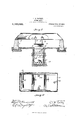
- Figure 1 is a vertical sectional view showing my shaft lowered into the ground and the lowering means.
- Fig. 2 is a transverse horizontal sectional view on the line 2 2 of Fig. 1.
- Fig. 3 is an enlarged vertical sectional view of the lower end of the shaft showing the valves and supply pipes for supplying the concrete for sealing the lower end of the mine shaft.
- Fig. 4 is a side elevation of the lower end of the shaft, looking from the end and partially broken away to show the arrangement of the concrete supply pipes.
- Fig. 5 is an enlarged vertical sectional view of one side of the lower end of the shaft, showing the wooden form in position and showing the concrete in position to seal the lower end of the mining shaft.
- Fig. 6 is a vertical sectional view similar to Fig. 5, showing the shaft made of reinforced concrete instead of steel.
- Fig. 1, 1 represents the concrete abutments or piers which are preferably four in number, supporting two setsl of double acting trusses 2, secured together by any number of desired braces and supporting at their center the two sets of transverse I-beams 3 and L1, which support four heavy jackscrews 5, which have their lower ends connected to the upper end of the mining shaft 6, in any desired manner, whereby the shaft is lowered into the ground.
- four hydraulic jacks will be used for forcing the same downwardly should the mine shaft refuse to travel downward'ly by force of gravity.
- the mining shaft 6 is formed in sections, as indicated by 7 8, 9 and 10in Fig. 1 of the drawings. While I have shown the four sections in Fig. 1 of the drawings, it will be seen that the same is broken away and, therefore, any desired number of sections are used according to the depth of the mine. Each of these sections is formed of horizontal L-channel or T-beams ll, and their ends are mitered at all corners and braced transverse the mining shaft by two I-beams 13 and 14. Vertical L-beains 12 are to be placed on the inside of all corners or angles and are to extend to the bottom of the shaft.
- the outer casing of the mining shaft as heretofore stated, is formed of boiler steel and is riveted to the vertical L-beams 12 and to the horizontal beams 11.
- the plates of boiler steel forming the casing are of such a width and length that they only extend partially over the vertical flange of the L-shaped beam 11, as clearly shown in Fig. 3, of the drawing, whereby the adjoining section extends over the remainder of the vertical portion of the L-shaped beam 11, and the two sections may be rigidly secured together.
- the mining shaft is formed in sec-l tions and riveted together as the mine is dug, thus producing a mining shaft in which the several sections can be taken apart and used again when removed.
- Vertical L-beams 17 are placed on the inside on all sides of the shaft for the purpose of strengthening the boiler plate.
- the lower end of the lower section 10 of the shaft is provided with an outwardly flared portion 15, having at its upper end the solid head 16, and at its lower end the tapered portion 17.
- the inner end of the portion 17 and the head 16 are connected by the plate 18, whereby a continuous space 19 is formed between the port-ion 15 and the plate 18, and entirely around the lower end of the shaft.
- This space is connected at each end by two pipes 20 and 21, and connected at their upper ends to the coupling 22, which has a vertical supply pipe 23 extending from the upper end of the mine for supplying concrete to the spaces 19, as will be hereinafter more fully described.
- the space 19 at each side is provided with three upwardly extending pipes 24, 25 and 26, which are connected to the valve 27, which is, ofy a threeway type and is supplied with the concrete vertical pipe 28.
- the valve 27 which is, ofy a threeway type and is supplied with the concrete vertical pipe 28.
- the space 19 is provided with a horizontal partition 30, extending entirely around the same and forming a space 31 between the plate 14 and the plate 30.
- the plate 30 is provided with openings 32, which communicate with the pipes 33 and 34, said pipe 33 leading inwardly through the plate 31, while the pipe 34 leads outwardly through the plate 15.
- the openings 32 are controlled by a slide valve 35, ⁇ whereby the concrete or cement mixture may be allowed to pass through either the pipe 33 or 34, as will be hereinafter more fully described.
- the space 19 above the. plate 30 is provided with a series of valves 36, which form communication with the space 19 and the space surrounding the mining shaft.l l1 ⁇ hese valves are of the screw form, as clearly shown and. adapted to screw outwardly when itis de.- sired to open them.
- the shaftl casing above the flared portion 15 is provided with a series of screw valves 37, which are adapted to be opened eutwardly and allow the water to pass within the mining shaft when desired, and for a purpose hereinafter more fully described.
- Each section is about four feet in height and is provided with a series of openings 38, which are screw-threaded and plugged so that the desired water pipes can be connected thereto, which lead from pumps for forcing the water out through the lining causing the earth around the tube to loosen up and consequently allowing the shaft to, settle, as desired. 1 have not shown or described the form ofk pump and means of removing the earth from the bottom of the shaft as this could be variedV and formsno partof my invention.
- the mining shaft is lowered into the ground by the screw-jacks 5,A as heretofore described andthe water pipes are connected to the openings 38, washing the earth from around the shaft and allowing the shaft to settle, as desired.
- the shaft has been lowered sufficiently in the ground, another section is placed thereon and the water pipes also connected to the section just put into position and the shaft is gradually lowered into the ground coupling section after section together until the desired depth is reached.
- a wooden curbing 39 is placed in a vertical position around the lower end of the mining shaft having its outer face flush with the upper end of the slanting wall 31.
- a false bottom 40 is placed across the bottom of the shaft and abuts the vertical wall 3,9, as clearly shown in Fig. 5 of the drawing.
- valves 3G are then open and the sliding valve is also opened which allows the concrete to fill the space 42, and also the space 43,y as clearly shown in Fig. 5 of the drawing.
- the valves 37 are also open,A which allows the water surrounding the mining shaft to pass inwardly within the shaft for the purpose of relieving the head of water and allowing water on the outside of the shaft to remain still and quiet during the sealing process. From this description it will be seen that the lower end of the mine shaft is perfectly sealed and made water-tight and air-tight and it is impossible for any water to find its way into the mining shaft after the valves 37 are closed.
- the openings 38 are closed by screw-plugs after the water pipes are disconnected, which aljso makes a watertight shaft. r1 ⁇ he false-bottom 40 and also the cm'bing 39 are removed and the val ve-stcms 35, 36 and 37 are sawed olf and all concrete pipes removed, leaving one uniform space from bottom to top of shaft.
- 1 instead of making the lining of boiler steel, as shown in other figures, 1 form it of reinforced concrete.
- This is accomplished by making the shoe 44 above the portion 45 of a double wall construction, as indicated at 4G. Between the walls of this double wall portion the reinforced concrete is formed and bolts 47 pass therethrough, whereby the shoe is locked to the lower end of the reinforced concrete lining.
- the pipes 23, which supply the shoe with concrete or cement, enter the shoe at the sides, as indicated at 48, instead of at the top, as shownv in the other figures. This is necessary as the reinforced concrete rests upon the upper end of the shoe and it would be. impossible for the pipes to enter at the top, as shown in the other figures.
- the "ivalves 36 pass through the double walled portion of the shoe and through the concrete and operate in the same manner as shown in the other figures.
- a mining shaft formed of a series of sections riveted together and having at its lower end a downwardl flared cement receiving pocket, means or feeding cement thereto from the upper end of the shaft, and means for distributing the cement from said pocket on the inside and outside of the shaft.
- a mining shaft formed of a series of sections secured together and having a 'pocket formed at its lower end, means for feeding the pocket with cement from the upper end of the shaft, valves for allowing the cement to pass from the pocket on the inside and outside of the shaft for sealing the lower end of the shaft.
- a mining shaft comprising a series of sections adapted to be secured together as the shaft is lowered into the ground, and means for sealing the lower end of the shaft on the inside and outside with cement, substantially as shown and described.
- a mining shaft comprising a series of sections adapted to be riveted together as the shaft is lowered into thefground, means for supporting the shaft and lowering it into the ground, and means carried by the lower end of the shaft for sealing it with cement when it has been lowered into the ground at the desired distance.
- a mining shaft having a pocket at its lower end and adapted to be lowered into the ground, valves carried by the shaft above the pocket, means for supplying the pocket with cement, means for allowing the cement to pass from the pocket on the inside and outside thereof for sealing the lower end of the shaft and means for allowing the water on the outside of the shaft to pass within the same.
- a mining shaft comprising a shaft having plugged openings, whereby water pipes may be connected thereto, the lower end of the shaft having a pocket, means for snpplying the pocket with cement, means for discharging the cement from the pocket on the inside and outside thereof for sealing the lower end of the shaft and valves carried by the casing above the pocket for allowing the water to pass from the outside of the shaft within the same.
- a mining shaft comprising a series of sections riveted together, to form a watertight shaft, the lower end of the shaft having an outwardly flared pocket, means for feeding cement to said pocket, means for discharging the cement from said pocket on the inside and outside of the shaft, and valves in the shaft above the pocket for allowing the water to pass from the outside of the shaft within the shaft.
- a mining shaft comprising a series of sections riveted together, a pocket carried by the lower end of the shaft, a wooden partition adjacent the pocket, a false bottom extending across the interior of the shaft at the upper end of the partition, means for supplying cement from the pocket to and filling the space between the partition and the inside of the shaft, means for supplying the out-side of the shaft with cement from the pocket at the lower end thereof, and means for allowing the water to pass from around the shaft within the same, substantially as shown and described.
- a mining shaft having a pocket formed at its lower end, means for feeding the pocket with cement from the upper end, valves for allowing the cement to pass from the pocket from the inside and outside of the shaft for sealing the lower end thereof.
Landscapes
- Engineering & Computer Science (AREA)
- Mining & Mineral Resources (AREA)
- Mechanical Engineering (AREA)
- Life Sciences & Earth Sciences (AREA)
- General Life Sciences & Earth Sciences (AREA)
- Geochemistry & Mineralogy (AREA)
- Geology (AREA)
- Earth Drilling (AREA)
Description
C. B. ROWLEY.
MINING SHAFT.
APPLIOATION FILED MAY 1a, 1913.
1,100,622, 1 PatentedJune 16,1914.
3 SHEETS-SHBBT 1.
6341 (wml/11mm@ COLUMBIA PILIIOURPH C0.. WASHINGTON. D. C.
C. B. ROWLEY.
MINING SHAFT.
APPLICATION FILED MAY 13, 1913.
1,100,622, Patented June 16,1914.
s SHEETS-SEHEN.
IIIIIIUHL,
WITNESSES l C, @UWE/V701? OLUIIIA PMNOGRAPH C0., WASHINGTON, D. C.
C. B. ROWLEY.
MINING SHAFT.
APPLICATION FILED MAY 13, 1913.
1,100,622. Patented June 16,1914
3 SHEETS-SHEET 3.
WITNESSES INVENTOR @7 Allorney coLUlnllA PLANOGRAPH Co.. WASHxNuToN, D. c.
CHARLIE B. ROWLEY, OF BRAINERD, MINNESOTA.
MINING-SHAFT.
Specification of Letters Patent.
Patented June 16, 1914.
Application inea May 13, 17913. serial No. 767,330.
To all whom 'it may concern Be it known that I, CHARLIE B. RowLEY, a citizen of the United States, residing at Brainerd, in the county of Crow Wing and State of Minnesota, have invented certain new and useful Improvements in Mining- Shafts, of which the following is a specification, reference being had therein to the accompanying drawing.
My invention relates to improvements in mining shafts.
rIhe object of my invention is to provide a mining shaft made up of angle-irons and covered by boiler steel and so riveted or bolted together that an air-tight and watertight sectional casing is formed and lowered into the ground, as the excavating is done on the inside and when this is completed this forms a mine shaft.
Another object of my invention is to provide a simple, cheap and effective means for supporting and lowering the shaft into the ground as the opening is dug in any desired manner.
A still further object of my invention. is to provide a simple, cheap and more effective device of this character provided with means for sealing the lower end of the shaft with concrete after the desired depth has been reached.
In the accompanying drawing: Figure 1 is a vertical sectional view showing my shaft lowered into the ground and the lowering means. Fig. 2 is a transverse horizontal sectional view on the line 2 2 of Fig. 1. Fig. 3 is an enlarged vertical sectional view of the lower end of the shaft showing the valves and supply pipes for supplying the concrete for sealing the lower end of the mine shaft. Fig. 4 is a side elevation of the lower end of the shaft, looking from the end and partially broken away to show the arrangement of the concrete supply pipes. Fig. 5 is an enlarged vertical sectional view of one side of the lower end of the shaft, showing the wooden form in position and showing the concrete in position to seal the lower end of the mining shaft. Fig. 6 is a vertical sectional view similar to Fig. 5, showing the shaft made of reinforced concrete instead of steel.
Referring now to the drawings, especially to Fig. 1, 1 represents the concrete abutments or piers which are preferably four in number, supporting two setsl of double acting trusses 2, secured together by any number of desired braces and supporting at their center the two sets of transverse I-beams 3 and L1, which support four heavy jackscrews 5, which have their lower ends connected to the upper end of the mining shaft 6, in any desired manner, whereby the shaft is lowered into the ground. It will be understood that in some instances four hydraulic jacks will be used for forcing the same downwardly should the mine shaft refuse to travel downward'ly by force of gravity.
The mining shaft 6 is formed in sections, as indicated by 7 8, 9 and 10in Fig. 1 of the drawings. While I have shown the four sections in Fig. 1 of the drawings, it will be seen that the same is broken away and, therefore, any desired number of sections are used according to the depth of the mine. Each of these sections is formed of horizontal L-channel or T-beams ll, and their ends are mitered at all corners and braced transverse the mining shaft by two I-beams 13 and 14. Vertical L-beains 12 are to be placed on the inside of all corners or angles and are to extend to the bottom of the shaft. The outer casing of the mining shaft, as heretofore stated, is formed of boiler steel and is riveted to the vertical L-beams 12 and to the horizontal beams 11. The plates of boiler steel forming the casing are of such a width and length that they only extend partially over the vertical flange of the L-shaped beam 11, as clearly shown in Fig. 3, of the drawing, whereby the adjoining section extends over the remainder of the vertical portion of the L-shaped beam 11, and the two sections may be rigidly secured together.
By the structure just described, it will be seen that the mining shaft is formed in sec-l tions and riveted together as the mine is dug, thus producing a mining shaft in which the several sections can be taken apart and used again when removed. Vertical L-beams 17 are placed on the inside on all sides of the shaft for the purpose of strengthening the boiler plate.
The lower end of the lower section 10 of the shaft is provided with an outwardly flared portion 15, having at its upper end the solid head 16, and at its lower end the tapered portion 17. vThe inner end of the portion 17 and the head 16 are connected by the plate 18, whereby a continuous space 19 is formed between the port-ion 15 and the plate 18, and entirely around the lower end of the shaft. This space is connected at each end by two pipes 20 and 21, and connected at their upper ends to the coupling 22, which has a vertical supply pipe 23 extending from the upper end of the mine for supplying concrete to the spaces 19, as will be hereinafter more fully described. The space 19 at each side is provided with three upwardly extending pipes 24, 25 and 26, which are connected to the valve 27, which is, ofy a threeway type and is supplied with the concrete vertical pipe 28. By this arrangement it will be seen that the concrete from the pipe 28 may be discharged into any one of the three pipes 24, 25 and 26.1 The continuous space 19 around the lower end of the shaft between each pi e connection is provided with an oblique y arranged partition 2.9, whereby separate compartments are formed and each compartment supplied by a separate pipe.
The space 19 is provided with a horizontal partition 30, extending entirely around the same and forming a space 31 between the plate 14 and the plate 30.. The plate 30 is provided with openings 32, which communicate with the pipes 33 and 34, said pipe 33 leading inwardly through the plate 31, while the pipe 34 leads outwardly through the plate 15. The openings 32 are controlled by a slide valve 35,` whereby the concrete or cement mixture may be allowed to pass through either the pipe 33 or 34, as will be hereinafter more fully described. The space 19 above the. plate 30 is provided with a series of valves 36, which form communication with the space 19 and the space surrounding the mining shaft.l l1`hese valves are of the screw form, as clearly shown and. adapted to screw outwardly when itis de.- sired to open them.
The shaftl casing above the flared portion 15 is provided with a series of screw valves 37, which are adapted to be opened eutwardly and allow the water to pass within the mining shaft when desired, and for a purpose hereinafter more fully described. Each section is about four feet in height and is provided with a series of openings 38, which are screw-threaded and plugged so that the desired water pipes can be connected thereto, which lead from pumps for forcing the water out through the lining causing the earth around the tube to loosen up and consequently allowing the shaft to, settle, as desired. 1 have not shown or described the form ofk pump and means of removing the earth from the bottom of the shaft as this could be variedV and formsno partof my invention.
The mining shaft is lowered into the ground by the screw-jacks 5,A as heretofore described andthe water pipes are connected to the openings 38, washing the earth from around the shaft and allowing the shaft to settle, as desired. lVhen the shaft has been lowered sufficiently in the ground, another section is placed thereon and the water pipes also connected to the section just put into position and the shaft is gradually lowered into the ground coupling section after section together until the desired depth is reached. After this operation is completed a wooden curbing 39 is placed in a vertical position around the lower end of the mining shaft having its outer face flush with the upper end of the slanting wall 31. A false bottom 40 is placed across the bottom of the shaft and abuts the vertical wall 3,9, as clearly shown in Fig. 5 of the drawing.
Concrete is fed through the pipes 23 and 28 and through the branch pipes 20, 21, 24 25 and 2G to the spaces 19. The valves 3G are then open and the sliding valve is also opened which allows the concrete to fill the space 42, and also the space 43,y as clearly shown in Fig. 5 of the drawing. The valves 37 are also open,A which allows the water surrounding the mining shaft to pass inwardly within the shaft for the purpose of relieving the head of water and allowing water on the outside of the shaft to remain still and quiet during the sealing process. From this description it will be seen that the lower end of the mine shaft is perfectly sealed and made water-tight and air-tight and it is impossible for any water to find its way into the mining shaft after the valves 37 are closed. The openings 38 are closed by screw-plugs after the water pipes are disconnected, which aljso makes a watertight shaft. r1`he false-bottom 40 and also the cm'bing 39 are removed and the val ve- stcms 35, 36 and 37 are sawed olf and all concrete pipes removed, leaving one uniform space from bottom to top of shaft.
1n the form shown in Fig. G, instead of making the lining of boiler steel, as shown in other figures, 1 form it of reinforced concrete. This is accomplished by making the shoe 44 above the portion 45 of a double wall construction, as indicated at 4G. Between the walls of this double wall portion the reinforced concrete is formed and bolts 47 pass therethrough, whereby the shoe is locked to the lower end of the reinforced concrete lining. In this form the pipes 23, which supply the shoe with concrete or cement, enter the shoe at the sides, as indicated at 48, instead of at the top, as shownv in the other figures. This is necessary as the reinforced concrete rests upon the upper end of the shoe and it would be. impossible for the pipes to enter at the top, as shown in the other figures. The "ivalves 36 pass through the double walled portion of the shoe and through the concrete and operate in the same manner as shown in the other figures.
Having thus described my invention, what I claim and desire to secure by Letters Patent is:
l. A mining shaft formed of a series of sections riveted together and having at its lower end a downwardl flared cement receiving pocket, means or feeding cement thereto from the upper end of the shaft, and means for distributing the cement from said pocket on the inside and outside of the shaft.
2. A mining shaft formed of a series of sections secured together and having a 'pocket formed at its lower end, means for feeding the pocket with cement from the upper end of the shaft, valves for allowing the cement to pass from the pocket on the inside and outside of the shaft for sealing the lower end of the shaft.
3. A mining shaft comprising a series of sections adapted to be secured together as the shaft is lowered into the ground, and means for sealing the lower end of the shaft on the inside and outside with cement, substantially as shown and described.
4. A mining shaft comprising a series of sections adapted to be riveted together as the shaft is lowered into thefground, means for supporting the shaft and lowering it into the ground, and means carried by the lower end of the shaft for sealing it with cement when it has been lowered into the ground at the desired distance.
5. A mining shaft having a pocket at its lower end and adapted to be lowered into the ground, valves carried by the shaft above the pocket, means for supplying the pocket with cement, means for allowing the cement to pass from the pocket on the inside and outside thereof for sealing the lower end of the shaft and means for allowing the water on the outside of the shaft to pass within the same.
6. A mining shaft comprising a shaft having plugged openings, whereby water pipes may be connected thereto, the lower end of the shaft having a pocket, means for snpplying the pocket with cement, means for discharging the cement from the pocket on the inside and outside thereof for sealing the lower end of the shaft and valves carried by the casing above the pocket for allowing the water to pass from the outside of the shaft within the same.
7. The combination with a mining shaft, of a series of piers adjacent the same and having a truss-frame supported thereby, transverse I-beams carried by the trussframe, screw-jacks carried by the I-beams and connected with the mining shaft whereby the same may be lowered into the ground.
8. In combination with a mining shaft, four piers adjacent thereto, a truss-frame supported by the piers, two pairs of I-beams connecting and supported by the trussframe, screw-jacks supported by the I- beams and having flexible connections with the mining shaft whereby the same may be lowered and raised from the ground.
9. A mining shaft comprising a series of sections riveted together, to form a watertight shaft, the lower end of the shaft having an outwardly flared pocket, means for feeding cement to said pocket, means for discharging the cement from said pocket on the inside and outside of the shaft, and valves in the shaft above the pocket for allowing the water to pass from the outside of the shaft within the shaft.
l0. A mining shaft comprising a series of sections riveted together, a pocket carried by the lower end of the shaft, a wooden partition adjacent the pocket, a false bottom extending across the interior of the shaft at the upper end of the partition, means for supplying cement from the pocket to and filling the space between the partition and the inside of the shaft, means for supplying the out-side of the shaft with cement from the pocket at the lower end thereof, and means for allowing the water to pass from around the shaft within the same, substantially as shown and described.
11. A mining shaft, having a pocket formed at its lower end, means for feeding the pocket with cement from the upper end, valves for allowing the cement to pass from the pocket from the inside and outside of the shaft for sealing the lower end thereof.
In testimony whereof I hereunto afliX my signature in the presence of two witnesses.
CHARLIE B. ROVLEY.
Witnesses:
DONALD B. MCALPINE, EDWARD KRUEGER.
Copies of this patent may be obtained for ve cents each, by addressing 'che Commissioner of Patents, Washington, D. C.
Priority Applications (1)
| Application Number | Priority Date | Filing Date | Title |
|---|---|---|---|
| US76733013A US1100622A (en) | 1913-05-13 | 1913-05-13 | Mining-shaft. |
Applications Claiming Priority (1)
| Application Number | Priority Date | Filing Date | Title |
|---|---|---|---|
| US76733013A US1100622A (en) | 1913-05-13 | 1913-05-13 | Mining-shaft. |
Publications (1)
| Publication Number | Publication Date |
|---|---|
| US1100622A true US1100622A (en) | 1914-06-16 |
Family
ID=3168823
Family Applications (1)
| Application Number | Title | Priority Date | Filing Date |
|---|---|---|---|
| US76733013A Expired - Lifetime US1100622A (en) | 1913-05-13 | 1913-05-13 | Mining-shaft. |
Country Status (1)
| Country | Link |
|---|---|
| US (1) | US1100622A (en) |
Cited By (2)
| Publication number | Priority date | Publication date | Assignee | Title |
|---|---|---|---|---|
| US3378304A (en) * | 1966-05-23 | 1968-04-16 | Stearns Roger Corp | Spread-footed three-dimensional headframe and method of erecting same |
| US4797031A (en) * | 1986-06-06 | 1989-01-10 | Daiho Construction Co., Ltd. | Caisson sinking method |
-
1913
- 1913-05-13 US US76733013A patent/US1100622A/en not_active Expired - Lifetime
Cited By (2)
| Publication number | Priority date | Publication date | Assignee | Title |
|---|---|---|---|---|
| US3378304A (en) * | 1966-05-23 | 1968-04-16 | Stearns Roger Corp | Spread-footed three-dimensional headframe and method of erecting same |
| US4797031A (en) * | 1986-06-06 | 1989-01-10 | Daiho Construction Co., Ltd. | Caisson sinking method |
Similar Documents
| Publication | Publication Date | Title |
|---|---|---|
| US1853379A (en) | Caisson and method of and means for sinking the same | |
| US480127A (en) | o rourke | |
| US1100622A (en) | Mining-shaft. | |
| US2931187A (en) | Coffer-dam | |
| US538073A (en) | Robert l | |
| US629135A (en) | Subaqueous tunnel and method of constructing same. | |
| US29921A (en) | Driving piles by atmospheric pressure | |
| US718441A (en) | Method of making substructures for buildings. | |
| US360959A (en) | Apparatus for excavating tunnels | |
| US1006799A (en) | Reinforced-concrete lining for mine-shafts and method of the manufacture thereof. | |
| US367547A (en) | poetsch | |
| US576843A (en) | Richard s | |
| US784413A (en) | Subaqueous tunnel construction. | |
| US637137A (en) | Mining-caisson. | |
| US1870248A (en) | Method and apparatus for building retaining walls, piers, etc. | |
| US175158A (en) | Improvement in submarine excavating apparatus | |
| US620101A (en) | Art of constructing tunnels | |
| US427149A (en) | Apparatus for submarine exploration | |
| US1221068A (en) | Method of building and placing piers. | |
| US933776A (en) | Sinking shafts and the like. | |
| NO790527L (en) | PROCEDURE AND FACILITY FOR CONSTRUCTION OF AN UNDERGROUND CONSTRUCTION WITH VERTICAL WALLS, BASED ON AN UNDERGROUND TUNNEL | |
| US246655A (en) | Marine structure for water-works | |
| US745457A (en) | Subaqueous tunnel. | |
| US574729A (en) | gillespie | |
| US766132A (en) | Safety-shaft for quicksand or other dangerous ground. |