US11005298B2 - Wireless power maximum efficiency tracking by system control - Google Patents
Wireless power maximum efficiency tracking by system control Download PDFInfo
- Publication number
- US11005298B2 US11005298B2 US16/388,476 US201916388476A US11005298B2 US 11005298 B2 US11005298 B2 US 11005298B2 US 201916388476 A US201916388476 A US 201916388476A US 11005298 B2 US11005298 B2 US 11005298B2
- Authority
- US
- United States
- Prior art keywords
- transmitter
- inductor
- receiver
- current
- power
- Prior art date
- Legal status (The legal status is an assumption and is not a legal conclusion. Google has not performed a legal analysis and makes no representation as to the accuracy of the status listed.)
- Active, expires
Links
Images


Classifications
-
- H—ELECTRICITY
- H02—GENERATION; CONVERSION OR DISTRIBUTION OF ELECTRIC POWER
- H02J—CIRCUIT ARRANGEMENTS OR SYSTEMS FOR SUPPLYING OR DISTRIBUTING ELECTRIC POWER; SYSTEMS FOR STORING ELECTRIC ENERGY
- H02J50/00—Circuit arrangements or systems for wireless supply or distribution of electric power
- H02J50/10—Circuit arrangements or systems for wireless supply or distribution of electric power using inductive coupling
- H02J50/12—Circuit arrangements or systems for wireless supply or distribution of electric power using inductive coupling of the resonant type
-
- H—ELECTRICITY
- H02—GENERATION; CONVERSION OR DISTRIBUTION OF ELECTRIC POWER
- H02J—CIRCUIT ARRANGEMENTS OR SYSTEMS FOR SUPPLYING OR DISTRIBUTING ELECTRIC POWER; SYSTEMS FOR STORING ELECTRIC ENERGY
- H02J50/00—Circuit arrangements or systems for wireless supply or distribution of electric power
- H02J50/10—Circuit arrangements or systems for wireless supply or distribution of electric power using inductive coupling
-
- G—PHYSICS
- G05—CONTROLLING; REGULATING
- G05F—SYSTEMS FOR REGULATING ELECTRIC OR MAGNETIC VARIABLES
- G05F1/00—Automatic systems in which deviations of an electric quantity from one or more predetermined values are detected at the output of the system and fed back to a device within the system to restore the detected quantity to its predetermined value or values, i.e. retroactive systems
- G05F1/66—Regulating electric power
- G05F1/67—Regulating electric power to the maximum power available from a generator, e.g. from solar cell
-
- H—ELECTRICITY
- H02—GENERATION; CONVERSION OR DISTRIBUTION OF ELECTRIC POWER
- H02J—CIRCUIT ARRANGEMENTS OR SYSTEMS FOR SUPPLYING OR DISTRIBUTING ELECTRIC POWER; SYSTEMS FOR STORING ELECTRIC ENERGY
- H02J3/00—Circuit arrangements for AC mains or AC distribution networks
- H02J3/007—Arrangements for selectively connecting the load or loads to one or several among a plurality of power lines or power sources
- H02J3/0075—Arrangements for selectively connecting the load or loads to one or several among a plurality of power lines or power sources for providing alternative feeding paths between load and source according to economic or energy efficiency considerations, e.g. economic dispatch
-
- H—ELECTRICITY
- H02—GENERATION; CONVERSION OR DISTRIBUTION OF ELECTRIC POWER
- H02J—CIRCUIT ARRANGEMENTS OR SYSTEMS FOR SUPPLYING OR DISTRIBUTING ELECTRIC POWER; SYSTEMS FOR STORING ELECTRIC ENERGY
- H02J50/00—Circuit arrangements or systems for wireless supply or distribution of electric power
- H02J50/80—Circuit arrangements or systems for wireless supply or distribution of electric power involving the exchange of data, concerning supply or distribution of electric power, between transmitting devices and receiving devices
-
- H02J7/025—
-
- H02J7/80—
-
- H—ELECTRICITY
- H04—ELECTRIC COMMUNICATION TECHNIQUE
- H04B—TRANSMISSION
- H04B5/00—Near-field transmission systems, e.g. inductive or capacitive transmission systems
- H04B5/70—Near-field transmission systems, e.g. inductive or capacitive transmission systems specially adapted for specific purposes
- H04B5/79—Near-field transmission systems, e.g. inductive or capacitive transmission systems specially adapted for specific purposes for data transfer in combination with power transfer
Definitions
- Embodiments of the present invention are related to wireless power systems and, specifically, to wireless power maximum efficiency tracking by system controls.
- a wireless power charging system includes a transmitter coil that is driven to produce a time-varying magnetic field and a receiver coil that is positioned relative to the transmitter coil to receive the power transmitted in the time-varying magnetic field.
- RX receiver
- the wireless power transfer efficiency is improved by reducing the transmit and receive coil currents as follows. First, the transmitter causes the receiver to reduce the receive coil current to a small value based on the transmitter/receiver communication. Then the transmitter changes the operating parameters to increase the power provided to the receiver without decreasing efficiency or with only small decrease in efficiency. For example, the transmitter may increase the VBRG voltage (the DC voltage powering the transmit coil) or the operating frequency.
- the transmitter may increase the VBRG voltage (the DC voltage powering the transmit coil) or the operating frequency.
- a method for operating a wireless power transmitter in a wireless power transfer operation in which power is transferred wirelessly via a magnetic field generated by an inductor of the transmitter (e.g. induction coil) and inducing an AC current in an inductor of a wireless power receiver.
- the method comprises:
- the transmitter causing the AC current to have a first value
- the transmitter increasing an output power of the transmitter's inductor to increase an output power of the receiver.
- Some embodiments provide transmitters configured to perform the methods described above and below.
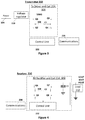
- FIGS. 1 and 2 illustrate wireless power transmission systems according to some embodiments.
- FIG. 3 illustrates a wireless power transmission transmitter according to some embodiments.
- FIG. 4 illustrates a wireless power transmission receiver according to some embodiments.
- FIG. 5 is a flowchart of a wireless power transmission operation according to some embodiments.
- FIG. 1 illustrates a system 100 for wireless transfer of power.
- a wireless power transmitter 102 drives a coil 106 to produce a magnetic field.
- a power supply 104 provides power to wireless power transmitter 102 .
- Power supply 104 can be, for example, a battery based supply or may be powered by alternating current, for example 120V at 60 Hz.
- Wireless power transmitter 102 drives coil 106 at, typically, a range of frequencies, typically according to one of the wireless power standards. Embodiments of the present invention may be used with any of the wireless power standards, or with any wireless power transmission system.
- FIG. 1 depicts a generalized wireless power system 100 that operates under any of these standards or in some other way.
- the magnetic field produced by coil 106 induces an AC current in coil 108 , which results in power being received in a receiver 110 .
- Receiver 110 provides power to a load 112 , which may be a battery charger and/or other components of a mobile device.
- Receiver 110 typically includes rectification to convert the received AC power to DC power for load 112 .
- the operating point is a function of the power demanded by the receiver 110 .
- the operating point is adjusted to meet Rx power requirements and is not always optimal in terms of reducing power consumption.
- the efficiency is a byproduct of the operating point, which is a function of the Tx VIN (a DC voltage generated by transmitter 102 from the output of power supply 104 ), or VBRG (a DC voltage generated by transmitter 102 from VIN and converted by a bridge inverter to AC current driven through coil 106 ), the resonance frequencies of the resonance tanks (Tx and Rx) formed with the coils 106 and 108 , the operating frequency limitations, and the Rx output voltage VOUT and power POUT that are delivered to load 112 .
- Tx VIN a DC voltage generated by transmitter 102 from the output of power supply 104
- VBRG a DC voltage generated by transmitter 102 from VIN and converted by a bridge inverter to AC current driven through coil 106
- efficiency can be increased by actively adjusting, rather than pre-setting and keeping fixed, operating parameters such as the operating frequency, the VBRG voltage, and the VOUT voltage.
- FIG. 2 illustrates an example wireless power transfer system 200 , having a transmitter 202 and a receiver 210 that can perform according to some embodiments of the present invention.
- transmitter 202 includes a control unit 222 that is coupled to control a TX coil driver 224 .
- Driver 224 is coupled to drive TX coil 106 with AC current.
- Control unit 222 is also coupled to receive and send data, possibly in packet form, through communications 226 .
- Communications 226 can, for example, transmit data to receiver 210 using a frequency modulation technique and receive data from receiver 210 that has been modulated with an amplitude modulation technique.
- receiver 210 includes a control unit 232 coupled to control operation of a RX rectifier 234 , which is coupled to Rx coil 108 .
- Control unit 232 is coupled to communications 236 which receives and sends data to transmitter 202 as described above.
- Control unit 222 and/or control unit 232 can be any processing system (microcontroller, memory, supporting circuitry) capable of operating transmitter 202 and receiver 210 , respectively.
- a transmitter 202 example is shown in more detail in FIG. 3 .
- a receiver 210 example is shown in more detail in FIG. 4 .
- System 200 is controlled to set the operating point by adjusting the VBRG and/or VOUT voltages according to the Rx output power POUT and the relative position on the Tx to maximize the efficiency. This is in contrast to fixing these key parameters and accepting the efficiency that results.
- the Rx 210 reports its output voltage VOUT, and/or output current IOUT, and/or Rx output power POUT, to transmitter 202 to enable TX 202 to estimate the Rx power.
- the Rx report is made by transmitting a Reported Power Packet (RPP).
- RPP Reported Power Packet
- a voltage regulator 310 in TX 202 can be used to adjust VBRG and/or VIN to force Rx 210 to request power level changes that result in the Tx 202 operating at the highest operating frequency, which in turn increases the inductive coupling of coils 106 , 108 and allows the system to operate to deliver the same power level POUT with the minimum current flowing through the Tx and Rx resonance tanks.
- V_Rx_coil is the voltage (EMF) across the receive coil 108 ; and f is the operating frequency (in Hz).
- V_Rx_coil and I_Tx_coil can be viewed as RMS (root mean square) values. Efficiency drops when I_Tx_coil or I_Rx_coil increases.
- the coil currents I_Tx_coil, I_Rx_coil are reduced while still delivering a high output power POUT to the load 112 using the operating point based on the receiver-transmitter communication because the voltages are all increased.
- voltage regulator 310 converts the power signal from power supply 104 to DC voltages VIN, VBRG (possibly under 5.0V; the invention is not limited to particular voltage values or other parameter values, which are provided for illustration).
- the voltage VBRG is input to a bridge inverter formed by switches Q 1 through Q 4 (possibly bipolar or field-effect transistors, e.g. NMOS). These switches, controlled by control unit 222 , form two pairs (Q 1 ,Q 4 ) and (Q 2 ,Q 3 ); one switch pair is open while the other one is closed, by control unit 222 , at the operating frequency f.
- AC current I_Tx_coil flows between the VBRG terminal and ground through a resonant tank formed by coil 106 and capacitor C 1 .
- the current amplitude, and hence the amplitude and rate of change (at a given operating frequency) of the magnetic field generated by the current, can be adjusted by adjusting the VBRG voltage for a given operating frequency and resonance tank.
- rectifier 234 is a synchronous rectifier including the transistors Q 5 through Q 8 controlled by control unit 232 (also in pairs or other combination to maximize efficiency and stability).
- the rectifier output is provided to load 112 .
- a capacitor C 3 and possibly other transmitter and receiver components, can be included to provide suitable operating parameters and functions.
- TX 202 and RX 210 communicate with each other to set the operating parameters.
- the transmitter causes the receiver to reduce the receive coil current I_Rx_coil to some minimal value.
- the communication protocol allows the transmitter to command the receiver to reduce the I_Rx_coil current to the minimal value at which the output current IOUT reaches zero or near zero, but does not stay at zero for any significant length of time. If the output current stayed at zero for a significant length of time, then the output power would be zero during this length of time, so efficiency would be zero and all power needed to maintain the wireless connection would be consumed with no power delivered.
- the receiver can reduce its coil current I_Rx_coil by reducing the duty cycle of transistors Q 5 -Q 8 for example, or by reducing the transistors' gate voltages.
- step 520 is performed as follows.
- the receiver's control unit 232 monitors the VOUT and/or IOUT and/or POUT and/or I_Rx_Coil value(s), and periodically provides those values to transmitter 202 .
- the transmitter gradually reduces the output power of coil 106 while monitoring the values received from the receiver, until those values indicate the minimal receive coil current I_Rx_coil, and/or until the receiver requests the transmitter to increase the output power.
- the transmitter can reduce its output power by reducing VBRG, and/or the operating frequency, and/or the duty cycle and/or gate voltages of switches Q 1 -Q 4 for example; in some embodiments however, the duty cycle is kept at 50%, and the operating frequency f is kept within certain bounds, e.g. depending on the transmitter's resonant tank frequency.) While the transmitter reduces the output power, the receiver attempts to maximize its output voltage and current VOUT, IOUT by operating the rectifier at 50% duty cycle with the maximum gate voltages.
- the transmitter increases its output power, for example by increasing the VBRG voltage, and/or operating frequency, and/or the bridge inverter's duty cycle and/or gate voltages.
- VOUT and POUT increase to desired values.
- the coil currents I_Tx_coil, I_Rx_coil also increase, but this increase is minimal relative to efficiency improvements because of first minimizing the I_Rx_coil current at step 520 as described above.
- the VBRG adjustment may continue throughout the power transfer operation, based on the receiver's reports of the VOUT and/or IOUT and/or POUT and/or I_Rx_coil parameters. In particular, steps 520 and 530 are periodically repeated during the power transfer.
- the transmitter and/or receiver duty cycles are fixed at 50% throughout, and are not changed at steps 520 and 530 .
- Clause 1 defines a method for operating a wireless power transmitter in a wireless power transfer operation in which power is transferred wirelessly via a magnetic field generated by an inductor (e.g. coil 106 ) of the transmitter and inducing an AC current in an inductor (e.g. coil 108 ) of a wireless power receiver, the method comprising:
- the transmitter causing the AC current to have a first value (for example, a low I_Rx_coil value at step 520 ); then
- the transmitter increasing an output power of the transmitter's inductor (e.g. at step 530 , possibly by increasing VBRG and/or the operating frequency) to increase an output power (e.g. POUT) of the receiver.
- the invention includes a transmitter configured to perform the methods described above, e.g. having a controller 222 suitably configured in a hardwired and/or software-programmed manner.
Landscapes
- Engineering & Computer Science (AREA)
- Power Engineering (AREA)
- Computer Networks & Wireless Communication (AREA)
- Physics & Mathematics (AREA)
- Sustainable Development (AREA)
- Sustainable Energy (AREA)
- Life Sciences & Earth Sciences (AREA)
- Electromagnetism (AREA)
- General Physics & Mathematics (AREA)
- Radar, Positioning & Navigation (AREA)
- Automation & Control Theory (AREA)
- Signal Processing (AREA)
- Charge And Discharge Circuits For Batteries Or The Like (AREA)
Abstract
Description
V_Rx_coil=2π*f*M*I_Tx_coil (1)
Loss=I_Tx_coil2*ACR_TX+I_Rx_coil2*ACR_RX (2)
where: I_Tx_coil is the RMS (root mean square) current in transmit
Claims (18)
Priority Applications (6)
| Application Number | Priority Date | Filing Date | Title |
|---|---|---|---|
| US16/388,476 US11005298B2 (en) | 2018-08-29 | 2019-04-18 | Wireless power maximum efficiency tracking by system control |
| KR1020190106024A KR20200026724A (en) | 2018-08-29 | 2019-08-28 | Wireless power maximum efficiency tracking by system control |
| JP2019156286A JP7004692B2 (en) | 2018-08-29 | 2019-08-29 | How to operate a wireless power transmitter and a wireless power transmitter using it |
| EP19194364.6A EP3618226B1 (en) | 2018-08-29 | 2019-08-29 | Wireless power maximum efficiency tracking by system control |
| CN201910811342.4A CN110875636B (en) | 2018-08-29 | 2019-08-29 | System Controlled Wireless Power Maximum Efficiency Tracking |
| KR1020200129714A KR102483807B1 (en) | 2018-08-29 | 2020-10-07 | Wireless power maximum efficiency tracking by system control |
Applications Claiming Priority (2)
| Application Number | Priority Date | Filing Date | Title |
|---|---|---|---|
| US201862724519P | 2018-08-29 | 2018-08-29 | |
| US16/388,476 US11005298B2 (en) | 2018-08-29 | 2019-04-18 | Wireless power maximum efficiency tracking by system control |
Publications (2)
| Publication Number | Publication Date |
|---|---|
| US20200076235A1 US20200076235A1 (en) | 2020-03-05 |
| US11005298B2 true US11005298B2 (en) | 2021-05-11 |
Family
ID=67809328
Family Applications (1)
| Application Number | Title | Priority Date | Filing Date |
|---|---|---|---|
| US16/388,476 Active 2039-05-07 US11005298B2 (en) | 2018-08-29 | 2019-04-18 | Wireless power maximum efficiency tracking by system control |
Country Status (5)
| Country | Link |
|---|---|
| US (1) | US11005298B2 (en) |
| EP (1) | EP3618226B1 (en) |
| JP (1) | JP7004692B2 (en) |
| KR (2) | KR20200026724A (en) |
| CN (1) | CN110875636B (en) |
Families Citing this family (3)
| Publication number | Priority date | Publication date | Assignee | Title |
|---|---|---|---|---|
| KR102813623B1 (en) * | 2020-03-25 | 2025-05-29 | 삼성전자주식회사 | Power supplying device and method for supplying electric power to one or more power receiving devices in wireless power supply system |
| CN111555612B (en) * | 2020-06-01 | 2023-07-14 | 重庆瑜欣平瑞电子股份有限公司 | A Maximum Efficiency Tracking Method of Magnetically Coupled Resonant Wireless Energy Transfer Based on Constant Output Voltage |
| US11336202B1 (en) * | 2021-05-12 | 2022-05-17 | Renesas Electronics America Inc. | Over voltage protection for wireless power receiver circuits |
Citations (24)
| Publication number | Priority date | Publication date | Assignee | Title |
|---|---|---|---|---|
| US20090243397A1 (en) * | 2008-03-05 | 2009-10-01 | Nigel Power, Llc | Packaging and Details of a Wireless Power device |
| US8129864B2 (en) | 2008-01-07 | 2012-03-06 | Access Business Group International Llc | Inductive power supply with duty cycle control |
| US20140009110A1 (en) * | 2012-07-09 | 2014-01-09 | Samsung Electronics Co., Ltd. | Method and apparatus for providing wireless charging power to a wireless power receiver |
| JP2014103751A (en) | 2012-11-19 | 2014-06-05 | Toshiba Corp | Wireless power transmission control device, power transmission device, power reception device, and wireless power transmission system |
| US8890470B2 (en) * | 2010-06-11 | 2014-11-18 | Mojo Mobility, Inc. | System for wireless power transfer that supports interoperability, and multi-pole magnets for use therewith |
| US20160094074A1 (en) | 2013-10-23 | 2016-03-31 | Apple Inc. | Method and Apparatus for Inductive Power Transfer |
| US20160329751A1 (en) | 2013-12-11 | 2016-11-10 | Powermat Technologies Ltd. | Wireless power transmission system and method controlled via digital messages |
| US9496732B2 (en) * | 2011-01-18 | 2016-11-15 | Mojo Mobility, Inc. | Systems and methods for wireless power transfer |
| WO2017080865A1 (en) | 2015-11-09 | 2017-05-18 | Koninklijke Philips N.V. | Wireless inductive power transfer |
| US20170149285A1 (en) * | 2014-05-14 | 2017-05-25 | WQC, Inc. | Wireless power transfer system |
| US20170194817A1 (en) * | 2014-10-28 | 2017-07-06 | Ihi Corporation | Power transmission device, power transmission method, and wireless power transfer system |
| US9722447B2 (en) * | 2012-03-21 | 2017-08-01 | Mojo Mobility, Inc. | System and method for charging or powering devices, such as robots, electric vehicles, or other mobile devices or equipment |
| US9837846B2 (en) * | 2013-04-12 | 2017-12-05 | Mojo Mobility, Inc. | System and method for powering or charging receivers or devices having small surface areas or volumes |
| US20180219405A1 (en) | 2017-02-02 | 2018-08-02 | Apple Inc. | Wireless Charging System With Duty Cycle Control |
| US20180241301A1 (en) * | 2015-09-17 | 2018-08-23 | Ihi Corporation | Power transmitter and wireless power transfer system |
| US10115520B2 (en) * | 2011-01-18 | 2018-10-30 | Mojo Mobility, Inc. | Systems and method for wireless power transfer |
| US20180342878A1 (en) * | 2015-09-17 | 2018-11-29 | Ihi Corporation | Power transmitter and wireless power transfer system |
| US20190199135A1 (en) * | 2016-08-29 | 2019-06-27 | Ihi Corporation | Power transmitter |
| US20200227946A1 (en) * | 2019-01-10 | 2020-07-16 | Hengchun Mao | High Performance Wireless Power Transfer and Power Conversion Technologies |
| US20200235784A1 (en) * | 2018-09-03 | 2020-07-23 | Lg Electronics Inc. | Device and method for transmitting data in wireless power transmission system |
| US20200244108A1 (en) * | 2017-06-28 | 2020-07-30 | Lg Electronics Inc. | Multi-coil based wireless power transmission device and method |
| US20200251929A1 (en) * | 2019-02-05 | 2020-08-06 | Mojo Mobility, Inc. | System and method for infrastructure, vehicle and internet of things wireless chargers |
| US20200251937A1 (en) * | 2016-06-08 | 2020-08-06 | Lg Electronics Inc. | Wireless power transmission method and device therefor |
| US20200252886A1 (en) * | 2017-05-01 | 2020-08-06 | Lg Electronics Inc. | Device and method for performing authentication in wireless power transmission system |
Family Cites Families (9)
| Publication number | Priority date | Publication date | Assignee | Title |
|---|---|---|---|---|
| JP3893290B2 (en) | 2002-01-09 | 2007-03-14 | キヤノン株式会社 | Capacitor charger and camera strobe charger |
| JP2013183496A (en) | 2012-02-29 | 2013-09-12 | Equos Research Co Ltd | Power transmission system |
| KR101601352B1 (en) * | 2012-09-26 | 2016-03-08 | 엘지이노텍 주식회사 | Apparatus for transmitting wireless power and method for controlling power thereof |
| JP6376201B2 (en) | 2013-04-08 | 2018-08-22 | ソニー株式会社 | Contactless power supply method |
| JPWO2015015771A1 (en) * | 2013-07-31 | 2017-03-02 | パナソニック株式会社 | Wireless power transmission system and power transmission device |
| JP6070503B2 (en) | 2013-10-15 | 2017-02-01 | ソニー株式会社 | Power receiving device, power receiving control method, power feeding system, and electronic device |
| EP2928038A1 (en) * | 2014-03-31 | 2015-10-07 | ABB Technology AG | Inductive power transfer system and method for operating an inductive power transfer system |
| JP6401672B2 (en) | 2015-07-22 | 2018-10-10 | 本田技研工業株式会社 | Power receiving device and non-contact power transmission method |
| JP6547554B2 (en) | 2015-09-29 | 2019-07-24 | 株式会社Ihi | Power transmission device and noncontact power feeding system |
-
2019
- 2019-04-18 US US16/388,476 patent/US11005298B2/en active Active
- 2019-08-28 KR KR1020190106024A patent/KR20200026724A/en not_active Abandoned
- 2019-08-29 JP JP2019156286A patent/JP7004692B2/en active Active
- 2019-08-29 EP EP19194364.6A patent/EP3618226B1/en active Active
- 2019-08-29 CN CN201910811342.4A patent/CN110875636B/en active Active
-
2020
- 2020-10-07 KR KR1020200129714A patent/KR102483807B1/en active Active
Patent Citations (24)
| Publication number | Priority date | Publication date | Assignee | Title |
|---|---|---|---|---|
| US8129864B2 (en) | 2008-01-07 | 2012-03-06 | Access Business Group International Llc | Inductive power supply with duty cycle control |
| US20090243397A1 (en) * | 2008-03-05 | 2009-10-01 | Nigel Power, Llc | Packaging and Details of a Wireless Power device |
| US8890470B2 (en) * | 2010-06-11 | 2014-11-18 | Mojo Mobility, Inc. | System for wireless power transfer that supports interoperability, and multi-pole magnets for use therewith |
| US9496732B2 (en) * | 2011-01-18 | 2016-11-15 | Mojo Mobility, Inc. | Systems and methods for wireless power transfer |
| US10115520B2 (en) * | 2011-01-18 | 2018-10-30 | Mojo Mobility, Inc. | Systems and method for wireless power transfer |
| US9722447B2 (en) * | 2012-03-21 | 2017-08-01 | Mojo Mobility, Inc. | System and method for charging or powering devices, such as robots, electric vehicles, or other mobile devices or equipment |
| US20140009110A1 (en) * | 2012-07-09 | 2014-01-09 | Samsung Electronics Co., Ltd. | Method and apparatus for providing wireless charging power to a wireless power receiver |
| JP2014103751A (en) | 2012-11-19 | 2014-06-05 | Toshiba Corp | Wireless power transmission control device, power transmission device, power reception device, and wireless power transmission system |
| US9837846B2 (en) * | 2013-04-12 | 2017-12-05 | Mojo Mobility, Inc. | System and method for powering or charging receivers or devices having small surface areas or volumes |
| US20160094074A1 (en) | 2013-10-23 | 2016-03-31 | Apple Inc. | Method and Apparatus for Inductive Power Transfer |
| US20160329751A1 (en) | 2013-12-11 | 2016-11-10 | Powermat Technologies Ltd. | Wireless power transmission system and method controlled via digital messages |
| US20170149285A1 (en) * | 2014-05-14 | 2017-05-25 | WQC, Inc. | Wireless power transfer system |
| US20170194817A1 (en) * | 2014-10-28 | 2017-07-06 | Ihi Corporation | Power transmission device, power transmission method, and wireless power transfer system |
| US20180241301A1 (en) * | 2015-09-17 | 2018-08-23 | Ihi Corporation | Power transmitter and wireless power transfer system |
| US20180342878A1 (en) * | 2015-09-17 | 2018-11-29 | Ihi Corporation | Power transmitter and wireless power transfer system |
| WO2017080865A1 (en) | 2015-11-09 | 2017-05-18 | Koninklijke Philips N.V. | Wireless inductive power transfer |
| US20200251937A1 (en) * | 2016-06-08 | 2020-08-06 | Lg Electronics Inc. | Wireless power transmission method and device therefor |
| US20190199135A1 (en) * | 2016-08-29 | 2019-06-27 | Ihi Corporation | Power transmitter |
| US20180219405A1 (en) | 2017-02-02 | 2018-08-02 | Apple Inc. | Wireless Charging System With Duty Cycle Control |
| US20200252886A1 (en) * | 2017-05-01 | 2020-08-06 | Lg Electronics Inc. | Device and method for performing authentication in wireless power transmission system |
| US20200244108A1 (en) * | 2017-06-28 | 2020-07-30 | Lg Electronics Inc. | Multi-coil based wireless power transmission device and method |
| US20200235784A1 (en) * | 2018-09-03 | 2020-07-23 | Lg Electronics Inc. | Device and method for transmitting data in wireless power transmission system |
| US20200227946A1 (en) * | 2019-01-10 | 2020-07-16 | Hengchun Mao | High Performance Wireless Power Transfer and Power Conversion Technologies |
| US20200251929A1 (en) * | 2019-02-05 | 2020-08-06 | Mojo Mobility, Inc. | System and method for infrastructure, vehicle and internet of things wireless chargers |
Non-Patent Citations (2)
| Title |
|---|
| European Communication with European Search Report for European Application No. 19194364.6, dated Dec. 17, 2019, pp. 1-7. |
| Office Action dated Jan. 5, 2021 issued in related Japanese patent application No. 2019-156286 (5 pages). |
Also Published As
| Publication number | Publication date |
|---|---|
| EP3618226B1 (en) | 2022-06-01 |
| KR20200120892A (en) | 2020-10-22 |
| KR102483807B1 (en) | 2022-12-30 |
| KR20200026724A (en) | 2020-03-11 |
| JP7004692B2 (en) | 2022-01-21 |
| US20200076235A1 (en) | 2020-03-05 |
| JP2020048403A (en) | 2020-03-26 |
| EP3618226A1 (en) | 2020-03-04 |
| CN110875636A (en) | 2020-03-10 |
| CN110875636B (en) | 2024-02-13 |
Similar Documents
| Publication | Publication Date | Title |
|---|---|---|
| KR102152691B1 (en) | Apparatus for contolling the charging, method for controlling the charging and apparatus for receiving wireless power having the same | |
| US10454306B2 (en) | Wireless power receiver and power control method thereof | |
| JP5135204B2 (en) | Non-contact power transmission system and load device in the non-contact power transmission system | |
| KR101806592B1 (en) | Apparatus for transmitting wireless power and method for transmitting wireless power | |
| EP3787152B1 (en) | Inductive power outlet and corresponding receiver | |
| US20150130292A1 (en) | Voltage converter, wireless power reception device and wireless power transmission system including the same | |
| US9773609B2 (en) | Power supply apparatus and power control method thereof | |
| CN108092416A (en) | Wireless power transmitter and method of controlling power therefor | |
| TW201347346A (en) | Wireless power receiver and power management method thereof | |
| WO2014132773A1 (en) | Power receiving device, receiving power regulation method, receiving power regulation program, and semiconductor device | |
| US20140292099A1 (en) | Wireless power apparatus and operation method thereof | |
| KR102483807B1 (en) | Wireless power maximum efficiency tracking by system control | |
| US20160261144A1 (en) | Power supplying apparatus and wireless power transmitter | |
| KR101438880B1 (en) | Apparatus for transmitting wireless power and method for transmitting wireless power | |
| US11996707B2 (en) | Wireless power transfer power control techniques | |
| KR102015095B1 (en) | Apparatuses and related methods for communication with a wireless power receiver | |
| KR101839527B1 (en) | Power apparatus with adjusting the rectified voltage for high efficiency wireless power transfer | |
| US20240340041A1 (en) | System and method for coded communication signals regulating inductive power transmissions | |
| KR101405806B1 (en) | Apparatus for supplying power and apparatus for transmitting wireless power and method for supplying power | |
| KR102091215B1 (en) | Wireless power transmitting apparatus and wireless power receiving apparatus | |
| Kao et al. | Contactless Power and Bidirectional Data Transmission via Magnetic Field [J] | |
| Huang et al. | Analysis and implementation of wireless power transfer system with phase and supply modulation control |
Legal Events
| Date | Code | Title | Description |
|---|---|---|---|
| FEPP | Fee payment procedure |
Free format text: ENTITY STATUS SET TO UNDISCOUNTED (ORIGINAL EVENT CODE: BIG.); ENTITY STATUS OF PATENT OWNER: LARGE ENTITY |
|
| AS | Assignment |
Owner name: INTEGRATED DEVICE TECHNOLOGY, INC., CALIFORNIA Free format text: ASSIGNMENT OF ASSIGNORS INTEREST;ASSIGNORS:SMITH, NICHOLAUS;LIU, RUI;BAVISI, AMIT D.;AND OTHERS;SIGNING DATES FROM 20150326 TO 20190912;REEL/FRAME:051413/0447 |
|
| STPP | Information on status: patent application and granting procedure in general |
Free format text: NON FINAL ACTION MAILED |
|
| STPP | Information on status: patent application and granting procedure in general |
Free format text: RESPONSE TO NON-FINAL OFFICE ACTION ENTERED AND FORWARDED TO EXAMINER |
|
| STPP | Information on status: patent application and granting procedure in general |
Free format text: NOTICE OF ALLOWANCE MAILED -- APPLICATION RECEIVED IN OFFICE OF PUBLICATIONS |
|
| STPP | Information on status: patent application and granting procedure in general |
Free format text: PUBLICATIONS -- ISSUE FEE PAYMENT VERIFIED |
|
| STCF | Information on status: patent grant |
Free format text: PATENTED CASE |
|
| MAFP | Maintenance fee payment |
Free format text: PAYMENT OF MAINTENANCE FEE, 4TH YEAR, LARGE ENTITY (ORIGINAL EVENT CODE: M1551); ENTITY STATUS OF PATENT OWNER: LARGE ENTITY Year of fee payment: 4 |