US10994614B2 - Pump system for vehicles - Google Patents
Pump system for vehicles Download PDFInfo
- Publication number
- US10994614B2 US10994614B2 US16/192,973 US201816192973A US10994614B2 US 10994614 B2 US10994614 B2 US 10994614B2 US 201816192973 A US201816192973 A US 201816192973A US 10994614 B2 US10994614 B2 US 10994614B2
- Authority
- US
- United States
- Prior art keywords
- pumps
- vehicle
- power
- internal combustion
- combustion engine
- Prior art date
- Legal status (The legal status is an assumption and is not a legal conclusion. Google has not performed a legal analysis and makes no representation as to the accuracy of the status listed.)
- Active, expires
Links
Images


Classifications
-
- B—PERFORMING OPERATIONS; TRANSPORTING
- B60—VEHICLES IN GENERAL
- B60L—PROPULSION OF ELECTRICALLY-PROPELLED VEHICLES; SUPPLYING ELECTRIC POWER FOR AUXILIARY EQUIPMENT OF ELECTRICALLY-PROPELLED VEHICLES; ELECTRODYNAMIC BRAKE SYSTEMS FOR VEHICLES IN GENERAL; MAGNETIC SUSPENSION OR LEVITATION FOR VEHICLES; MONITORING OPERATING VARIABLES OF ELECTRICALLY-PROPELLED VEHICLES; ELECTRIC SAFETY DEVICES FOR ELECTRICALLY-PROPELLED VEHICLES
- B60L1/00—Supplying electric power to auxiliary equipment of vehicles
- B60L1/003—Supplying electric power to auxiliary equipment of vehicles to auxiliary motors, e.g. for pumps, compressors
-
- F—MECHANICAL ENGINEERING; LIGHTING; HEATING; WEAPONS; BLASTING
- F04—POSITIVE - DISPLACEMENT MACHINES FOR LIQUIDS; PUMPS FOR LIQUIDS OR ELASTIC FLUIDS
- F04B—POSITIVE-DISPLACEMENT MACHINES FOR LIQUIDS; PUMPS
- F04B17/00—Pumps characterised by combination with, or adaptation to, specific driving engines or motors
- F04B17/05—Pumps characterised by combination with, or adaptation to, specific driving engines or motors driven by internal-combustion engines
-
- B—PERFORMING OPERATIONS; TRANSPORTING
- B60—VEHICLES IN GENERAL
- B60K—ARRANGEMENT OR MOUNTING OF PROPULSION UNITS OR OF TRANSMISSIONS IN VEHICLES; ARRANGEMENT OR MOUNTING OF PLURAL DIVERSE PRIME-MOVERS IN VEHICLES; AUXILIARY DRIVES FOR VEHICLES; INSTRUMENTATION OR DASHBOARDS FOR VEHICLES; ARRANGEMENTS IN CONNECTION WITH COOLING, AIR INTAKE, GAS EXHAUST OR FUEL SUPPLY OF PROPULSION UNITS IN VEHICLES
- B60K25/00—Auxiliary drives
- B60K25/06—Auxiliary drives from the transmission power take-off
-
- F—MECHANICAL ENGINEERING; LIGHTING; HEATING; WEAPONS; BLASTING
- F04—POSITIVE - DISPLACEMENT MACHINES FOR LIQUIDS; PUMPS FOR LIQUIDS OR ELASTIC FLUIDS
- F04B—POSITIVE-DISPLACEMENT MACHINES FOR LIQUIDS; PUMPS
- F04B19/00—Machines or pumps having pertinent characteristics not provided for in, or of interest apart from, groups F04B1/00 - F04B17/00
- F04B19/04—Pumps for special use
-
- F—MECHANICAL ENGINEERING; LIGHTING; HEATING; WEAPONS; BLASTING
- F04—POSITIVE - DISPLACEMENT MACHINES FOR LIQUIDS; PUMPS FOR LIQUIDS OR ELASTIC FLUIDS
- F04B—POSITIVE-DISPLACEMENT MACHINES FOR LIQUIDS; PUMPS
- F04B23/00—Pumping installations or systems
- F04B23/04—Combinations of two or more pumps
-
- A—HUMAN NECESSITIES
- A01—AGRICULTURE; FORESTRY; ANIMAL HUSBANDRY; HUNTING; TRAPPING; FISHING
- A01C—PLANTING; SOWING; FERTILISING
- A01C19/00—Arrangements for driving working parts of fertilisers or seeders
- A01C19/02—Arrangements for driving working parts of fertilisers or seeders by a motor
-
- B—PERFORMING OPERATIONS; TRANSPORTING
- B60—VEHICLES IN GENERAL
- B60L—PROPULSION OF ELECTRICALLY-PROPELLED VEHICLES; SUPPLYING ELECTRIC POWER FOR AUXILIARY EQUIPMENT OF ELECTRICALLY-PROPELLED VEHICLES; ELECTRODYNAMIC BRAKE SYSTEMS FOR VEHICLES IN GENERAL; MAGNETIC SUSPENSION OR LEVITATION FOR VEHICLES; MONITORING OPERATING VARIABLES OF ELECTRICALLY-PROPELLED VEHICLES; ELECTRIC SAFETY DEVICES FOR ELECTRICALLY-PROPELLED VEHICLES
- B60L2200/00—Type of vehicles
- B60L2200/40—Working vehicles
-
- B—PERFORMING OPERATIONS; TRANSPORTING
- B60—VEHICLES IN GENERAL
- B60R—VEHICLES, VEHICLE FITTINGS, OR VEHICLE PARTS, NOT OTHERWISE PROVIDED FOR
- B60R11/00—Arrangements for holding or mounting articles, not otherwise provided for
- B60R2011/0042—Arrangements for holding or mounting articles, not otherwise provided for characterised by mounting means
-
- B—PERFORMING OPERATIONS; TRANSPORTING
- B60—VEHICLES IN GENERAL
- B60Y—INDEXING SCHEME RELATING TO ASPECTS CROSS-CUTTING VEHICLE TECHNOLOGY
- B60Y2200/00—Type of vehicle
- B60Y2200/40—Special vehicles
-
- F—MECHANICAL ENGINEERING; LIGHTING; HEATING; WEAPONS; BLASTING
- F04—POSITIVE - DISPLACEMENT MACHINES FOR LIQUIDS; PUMPS FOR LIQUIDS OR ELASTIC FLUIDS
- F04B—POSITIVE-DISPLACEMENT MACHINES FOR LIQUIDS; PUMPS
- F04B2201/00—Pump parameters
- F04B2201/12—Parameters of driving or driven means
Definitions
- a pump system with multiple pumps and a power source.
- the power source can be a gasoline or other internal combustion engine.
- multiple pumps e.g., three or more pumps
- a single power source e.g., a single gasoline engine
- multiple pumps e.g., three or more pumps
- a single power transmission system can include a single flexible power transmission element configured to transfer power from a single power source (e.g., a single gasoline engine) to multiple pumps (e.g., three or more pumps).
- Some embodiments of the invention provide a vehicle-mounted pump system for use with a service vehicle.
- a chassis can be configured to be secured to the service vehicle, and a frame can be supported by the chassis.
- a plurality of pumps can be supported by the frame, with each of the pumps being configured to pump liquid for dispersal external to the service vehicle.
- a power source can be supported by at least one of the chassis and the frame.
- a power transmission system can be configured to transfer power from the power source to the plurality of pumps.
- Some embodiments of the invention provide a service vehicle having a battery, a first internal combustion engine, and a pulley-driven pump system.
- the pulley-driven pump system can include a chassis configured to be secured to the service vehicle, and a frame supported by the chassis. A plurality of pumps can be supported by the frame, with each of the pumps being configured to pump liquid for dispersal external to the service vehicle.
- the pulley-driven pump system can include a power source, which can be a second internal combustion engine different from the first internal combustion engine.
- the pulley-driven pump system can include a power transmission system configured to transfer power from the power source to the plurality of pumps.
- FIG. 1 is a front, right, top isometric view of a pump system according to one embodiment of the invention.
- FIG. 2 is a top plan view of the pump system of FIG. 1 .
- FIG. 3 is a right side elevation view of the pump system of FIG. 1 .
- FIG. 4 is a front elevation view of the pump system of FIG. 1 .
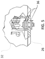
- FIG. 5 is an enlarged right side elevation view of area 5 - 5 of FIG. 3 , with certain components partially removed or illustrated in cross-section.
- FIG. 6 is a rear, right, top isometric view of select parts of the pump system of FIG. 1 .
- FIG. 7 is a rear, left, top isometric view of select parts of the pump system of FIG. 1 .
- FIG. 8 is a front, right, top isometric view of select parts of the pump system of FIG. 1 .
- the phrases “at least one of A, B, and C,” “one or more of A, B, and C,” and the like, are meant to indicate A, or B, or C (individually or plurally), or any combination of A, B, and/or C (individually or plurally), including one or more instances of A, one or more of instances B, and/or one or more of instances of C.
- pump systems for pumping one or more fluids.
- it may be useful to provide separate pumping for separate liquids e.g., for independent dispersal, or for simultaneous distribution from a dual-outlet or other spraying system).
- pump systems may be subject to size, weight, power, and other requirements or limits.
- pump systems may be configured to be mounted to, transported by, and operated from a vehicle (e.g., a service truck for landscape and lawn services). Accordingly, for example, it may be useful for a pump system to exhibit appropriate pump power while also being relatively lightweight, relatively compact in size, and capable of being operated using relatively portable power sources.
- a pump system according to the invention can include multiple pumps configured to separately provide pumping power for dispersal of multiple fluids (e.g., the same or different fluids from different fluid sources, such as on-vehicle tanks or other storage systems).
- the multiple pumps can be collectively mounted on a unified support structure, along with an associated power source, in order to provide a relatively compact system envelope.
- a single power source e.g., a single internal combustion engine
- a single flexible power transmission element such as a single belt
- a control device e.g., a powered control device, such as an electrical clutch
- a powered control device such as an electrical clutch
- a power source can also be configured to provide power to external systems (e.g., systems located remotely from the pump system).
- an internal combustion engine configured to power multiple pumps can also be configured to provide power to charge a vehicle battery (e.g., the battery of a service vehicle that carries the relevant pump system for in-field operations).
- a vehicle battery e.g., the battery of a service vehicle that carries the relevant pump system for in-field operations.
- an internal combustion engine of a pump system can be different from an internal combustion engine that powers a vehicle, such a service vehicle for landscape and lawn services, that carries the pump system.
- FIGS. 1-4 illustrate an example pump system 20 according to an embodiment of the invention.
- the pump system 20 can be configured to be secured to a vehicle 21 for operation, so that the pump system 20 can be transported between work sites on, and generally operated from, the vehicle 21 .
- the pump system 20 can be configured to be secured to a service vehicle (e.g., for landscape and lawn services), with pumps of the pump system 20 configured to pump chemicals for use in lawn care or other operations.
- a service vehicle e.g., for landscape and lawn services
- the pump system 20 can include any number of pumps and a power source.
- the pump system 20 beneficially includes three pumps 22 , and an internal combustion engine 24 , all of which are secured to and supported on a support chassis 26 .
- the support chassis 26 can be configured to be readily secured to the vehicle 21 , which can be a truck, service vehicle, or other vehicle. This may be useful, for example, in order to accommodate retrofitting of vehicles with the pump system 20 (or similar other systems).
- the pumps 22 can be powered by the engine 24 via a transmission system 28 .
- the transmission system 28 can include a set of pulleys or other rotating elements (not shown in FIGS. 1-4 ) connected by one or more belts or other flexible power transmission elements (not shown in FIGS. 1-4 ).
- the pulleys or other rotating elements can serve as one or more power outputs for the engine 24 and as one or more power inputs for the pumps 22 .
- a single belt or single other flexible power transmission element can be used to transfer rotational power from the engine 24 to a plurality of the pumps 22 .
- a frame 30 can be provided, to which the pumps 22 and the engine 24 can be secured, so that the frame 30 supports the pumps 22 and the engine 24 above the chassis 26 .
- the frame 30 can be configured in different ways, in order to support the pumps 22 and the engine 24 at appropriate locations and orientations.
- particular configurations of the frame 30 can be selected to provide appropriate clearance for operation and maintenance of the pumps 22 and the engine 24 . This may be useful, for example, in order to allow for convenient or efficient connections between the pumps 22 and the engine 24 and other systems (e.g., hoses of a sprayer system (not shown), or electrical components for an electrical system (not shown)), or to enable the pump system 20 as a whole to fit within a desired envelope (e.g., for inclusion in the limited space of a cargo platform of a vehicle).
- systems e.g., hoses of a sprayer system (not shown), or electrical components for an electrical system (not shown)
- a desired envelope e.g., for inclusion in the limited space of a cargo platform of a vehicle.
- the frame 30 can also provide shielding for certain system components.
- the frame 30 includes a multi-part shield 32 configured to at least partially cover part or all of the transmission system 28 (e.g., one or more belts) that transfers power from the engine 24 to the pumps 22 .
- the shield 32 can include removable panels (e.g., panels that are removable with hand tools, or via manual release of appropriate fasteners) in order to allow appropriate access to system components and/or useful customization for particular arrangements or contexts.
- two of the pumps 22 are mounted on the frame 30 on the same horizontal plane, and the third pump 22 is mounted substantially above the two pumps 22 that mounted on the frame 30 on the same horizontal plane.
- the third pump 22 can be mounted partly, substantially, or entirely above the other two pumps to provide appropriate clearance for operation and maintenance of the pumps 22 and the engine 24 .
- this can allow for convenient or efficient connections between the pumps 22 and the engine 24 and other systems (e.g., hoses of a sprayer system (not shown), or electrical components for an electrical system (not shown)), or enable the pump system 20 as a whole to fit within a desired envelope (e.g., for inclusion in the limited space of a cargo platform of a vehicle).
- different control devices can be provided.
- some embodiments can include an electrical or other clutch (not shown in FIGS. 1-4 ) to control operation of the pumps 22 (e.g., through electronic control of one or more pulleys associated with a belt that transfers power from the engine 24 to the pumps 22 ).
- one or more electronic controller e.g., one or more processor devices
- one or more system components e.g., electronics to control charging of batteries, as also discussed below, or other powering of external components.
- the pump system 20 can be configured to provide power to external components.
- the mechanical power generated by the engine 24 can be used to generate electricity (e.g., with equipment supported by the chassis 26 , or elsewhere).
- the resulting electricity can be used internally to the pump system 20 , such as for operation of an electrical clutch or for direct electronic control of the pumps 22 .
- the resulting electricity can be used externally to the pump system 20 , using an electrical transmission system (e.g., with wires 34 , as shown in FIG. 1 ).
- electrical power resulting from operation of the engine 24 can be transferred to a battery 25 (or other electrical system) of an associated vehicle 21 in order to charge the battery 25 (or otherwise power the other electrical system).
- electrical power from a vehicle battery (or other vehicle system) can be used by the pump system 20 for operation of components thereof (e.g., for operation of an electrical clutch or for direct electronic control of the pumps 22 ).
- an automatic disconnect circuit 23 can be configured to terminate an electrical connection, or otherwise stop transfer of electrical power, between an external system (e.g., a vehicle battery) and the pump system 20 (or certain components thereof) upon the vehicle engine being started or the occurrence of another condition.
- an external system e.g., a vehicle battery
- the pump system 20 or certain components thereof
- certain components can be secured with vibration dampening (or other specialized) fastener assemblies.
- some attachments between system components can include rubber washers 36 , or other dampening components. This arrangement, for example, can help to firmly secure components of the pump system 20 while also potentially reducing any detrimental effects of vibrations, impacts, or other undesired movements or events.
- FIGS. 6 through 8 illustrate an example configuration of the transmission system 28 of the pump system 20 , in which a belt-drive system supported by the frame 30 and shielded by the shield 32 (see, e.g., FIGS. 1-3 ) is adapted to transfer rotational power from the engine 24 (not shown in FIGS. 6 and 7 ) to each of the pumps 22 .
- a bushing 40 is configured to engage an output shaft 41 of the engine 24 in order to receive rotational power from the engine 24 .
- the bushing 40 is coupled to a pulley system, so that a belt or other flexible power transmission element can in turn transfer rotational power from the bushing 40 to the pumps 22 .
- the bushing 40 is connected to a dual pulley 42 that receives two cog-less v-belts 44 a and 44 b .
- the v-belt 44 a extends from a first rack of the pulley 42 around a larger pulley 46 that is secured to an input shaft of a first one of the pumps 22 , with a belt tensioner 48 adapted to ensure appropriate tension of the v-belt 44 a around the associated pulleys 42 , 46 .
- the pulley 46 is also engaged by an electrical clutch 50 , which can be controlled to allow or prevent operation of the associated pump 22 , as desired.
- the v-belt 44 b extends from a second track of the pulley 42 , around larger pulleys 52 , 54 that are secured, respectively, to input shafts of a second and third of the pumps 22 .
- a belt tensioner 48 is adapted to ensure appropriate tension of the v-belt 44 b around the associated pulleys 42 , 52 , 54 .
- the pulleys 52 , 54 are also engaged, respectively, by electrical clutches 58 , 60 , which can generally be controlled to allow or prevent operation of the associated pumps 22 , as desired.
- electrical power for operation and control of components of the pump system 20 can be provided from internal or external sources.
- electrical power to control the clutches 50 , 58 , 60 can be provided by a vehicle battery (not shown), which in turn can be recharged using power generated by the engine 24 (see, e.g., FIGS. 1-3 ).
- some embodiments can utilize more or fewer flexible power transmission elements than are illustrated in FIGS. 6 and 7 .
- a single belt (or other transmission element) can be used to transfer power to all of the pumps 22 , or a set of dedicated belts (or other transmission elements) can be used to transfer power to each of the pumps 22 individually.
- different clutch arrangements can be utilized, including arrangements with non-electrical clutches, with clutches disposed at different locations, or with individual clutches that can control power transmission to multiple pumps.
Landscapes
- Engineering & Computer Science (AREA)
- Mechanical Engineering (AREA)
- General Engineering & Computer Science (AREA)
- Power Engineering (AREA)
- Transportation (AREA)
- Chemical & Material Sciences (AREA)
- Combustion & Propulsion (AREA)
- Special Spraying Apparatus (AREA)
- Catching Or Destruction (AREA)
Abstract
Description
Claims (13)
Priority Applications (1)
| Application Number | Priority Date | Filing Date | Title |
|---|---|---|---|
| US16/192,973 US10994614B2 (en) | 2017-11-16 | 2018-11-16 | Pump system for vehicles |
Applications Claiming Priority (2)
| Application Number | Priority Date | Filing Date | Title |
|---|---|---|---|
| US201762587162P | 2017-11-16 | 2017-11-16 | |
| US16/192,973 US10994614B2 (en) | 2017-11-16 | 2018-11-16 | Pump system for vehicles |
Publications (2)
| Publication Number | Publication Date |
|---|---|
| US20190143818A1 US20190143818A1 (en) | 2019-05-16 |
| US10994614B2 true US10994614B2 (en) | 2021-05-04 |
Family
ID=66433110
Family Applications (1)
| Application Number | Title | Priority Date | Filing Date |
|---|---|---|---|
| US16/192,973 Active 2039-08-15 US10994614B2 (en) | 2017-11-16 | 2018-11-16 | Pump system for vehicles |
Country Status (1)
| Country | Link |
|---|---|
| US (1) | US10994614B2 (en) |
Cited By (1)
| Publication number | Priority date | Publication date | Assignee | Title |
|---|---|---|---|---|
| US20210388830A1 (en) * | 2020-06-12 | 2021-12-16 | Deere & Company | Demand based hydraulic pump control system |
Citations (11)
| Publication number | Priority date | Publication date | Assignee | Title |
|---|---|---|---|---|
| US5180108A (en) * | 1988-10-31 | 1993-01-19 | Fuji Jukogyo Kabushiki Kaisha | Truck with a power spray device |
| US6547527B2 (en) * | 2001-03-05 | 2003-04-15 | Fugitt Rubber & Supply Co., Ltd. | Generator unit with clutch-driven pump |
| US20030071062A1 (en) * | 2000-11-24 | 2003-04-17 | Miller Michelle Jean | Termite control system with multi-fluid proportion metering and batch signal metering |
| US6773238B1 (en) * | 1999-07-12 | 2004-08-10 | Kamat-Pumpen Gmbh & Co. Kg | Pumping device for discharging large amounts of liquid |
| US20090068031A1 (en) * | 2007-09-10 | 2009-03-12 | Philippe Gambier | Pump Assembly |
| US20100068071A1 (en) * | 2007-03-07 | 2010-03-18 | Frank Roger Bowden | Mobile work platform |
| US20110160920A1 (en) * | 2009-12-30 | 2011-06-30 | Orr David C | System and method for controlling fluid delivery |
| US20140311760A1 (en) * | 2013-04-19 | 2014-10-23 | Waterous Company | Top access to a pump module of a fire truck |
| US20150059330A1 (en) * | 2013-09-05 | 2015-03-05 | Caterpillar Inc. | Fluid delivery system |
| US9395049B2 (en) * | 2013-07-23 | 2016-07-19 | Baker Hughes Incorporated | Apparatus and methods for delivering a high volume of fluid into an underground well bore from a mobile pumping unit |
| US20180266412A1 (en) * | 2016-11-30 | 2018-09-20 | Impact Solutions As | Plant for controlling delivery of pressurized fluid in a conduit, and a method of controlling a prime mover |
-
2018
- 2018-11-16 US US16/192,973 patent/US10994614B2/en active Active
Patent Citations (11)
| Publication number | Priority date | Publication date | Assignee | Title |
|---|---|---|---|---|
| US5180108A (en) * | 1988-10-31 | 1993-01-19 | Fuji Jukogyo Kabushiki Kaisha | Truck with a power spray device |
| US6773238B1 (en) * | 1999-07-12 | 2004-08-10 | Kamat-Pumpen Gmbh & Co. Kg | Pumping device for discharging large amounts of liquid |
| US20030071062A1 (en) * | 2000-11-24 | 2003-04-17 | Miller Michelle Jean | Termite control system with multi-fluid proportion metering and batch signal metering |
| US6547527B2 (en) * | 2001-03-05 | 2003-04-15 | Fugitt Rubber & Supply Co., Ltd. | Generator unit with clutch-driven pump |
| US20100068071A1 (en) * | 2007-03-07 | 2010-03-18 | Frank Roger Bowden | Mobile work platform |
| US20090068031A1 (en) * | 2007-09-10 | 2009-03-12 | Philippe Gambier | Pump Assembly |
| US20110160920A1 (en) * | 2009-12-30 | 2011-06-30 | Orr David C | System and method for controlling fluid delivery |
| US20140311760A1 (en) * | 2013-04-19 | 2014-10-23 | Waterous Company | Top access to a pump module of a fire truck |
| US9395049B2 (en) * | 2013-07-23 | 2016-07-19 | Baker Hughes Incorporated | Apparatus and methods for delivering a high volume of fluid into an underground well bore from a mobile pumping unit |
| US20150059330A1 (en) * | 2013-09-05 | 2015-03-05 | Caterpillar Inc. | Fluid delivery system |
| US20180266412A1 (en) * | 2016-11-30 | 2018-09-20 | Impact Solutions As | Plant for controlling delivery of pressurized fluid in a conduit, and a method of controlling a prime mover |
Cited By (2)
| Publication number | Priority date | Publication date | Assignee | Title |
|---|---|---|---|---|
| US20210388830A1 (en) * | 2020-06-12 | 2021-12-16 | Deere & Company | Demand based hydraulic pump control system |
| US12196195B2 (en) * | 2020-06-12 | 2025-01-14 | Deere & Company | Demand based hydraulic pump control system |
Also Published As
| Publication number | Publication date |
|---|---|
| US20190143818A1 (en) | 2019-05-16 |
Similar Documents
| Publication | Publication Date | Title |
|---|---|---|
| US20070296223A1 (en) | Portable Combination Utility and Power Tool Unit | |
| US20220112832A1 (en) | Power systems and enclosures having an improved compressor drive | |
| US20090218327A1 (en) | Hydraulically driven tool system | |
| US12220976B2 (en) | Electric work vehicle | |
| US20080042625A1 (en) | Portable generator housing | |
| JP2012084340A (en) | Battery pack | |
| US20110226539A1 (en) | Vehicle with removable auxiliary power system | |
| WO2009099908A1 (en) | Service pack power management | |
| US20140049898A1 (en) | Container data center | |
| US11706896B2 (en) | Modular rack system and method | |
| US5739675A (en) | Removable powertray for a self contained motor generator set | |
| US10994614B2 (en) | Pump system for vehicles | |
| US11239521B2 (en) | Electrical power delivery system with a support structure | |
| US20180206401A1 (en) | Lawn care vehicle with on board battery charging | |
| US11102900B2 (en) | Electrical power delivery system | |
| US11464138B2 (en) | Module panel and method for an electrical power delivery system | |
| US8450863B2 (en) | Outlet box for power generator aggregate mounted on a frame to attenuate vibration and oscillation | |
| US5960637A (en) | Trailer refrigeration unit with pivotally mounted compressor and engine/generator set | |
| US6695565B1 (en) | Motorcycle loading and support assembly for a truck | |
| US20210017902A1 (en) | Engine driven welder | |
| US8186314B2 (en) | Generator cooling system and method | |
| CA2891727C (en) | Blower drive system for a vacuum truck | |
| US11052742B2 (en) | Mounting system for an electrical power delivery system | |
| EP2151349A1 (en) | Mobile power set | |
| US20070134104A1 (en) | Modular portable compressor |
Legal Events
| Date | Code | Title | Description |
|---|---|---|---|
| FEPP | Fee payment procedure |
Free format text: ENTITY STATUS SET TO UNDISCOUNTED (ORIGINAL EVENT CODE: BIG.); ENTITY STATUS OF PATENT OWNER: LARGE ENTITY |
|
| STPP | Information on status: patent application and granting procedure in general |
Free format text: DOCKETED NEW CASE - READY FOR EXAMINATION |
|
| STPP | Information on status: patent application and granting procedure in general |
Free format text: NON FINAL ACTION MAILED |
|
| STPP | Information on status: patent application and granting procedure in general |
Free format text: NOTICE OF ALLOWANCE MAILED -- APPLICATION RECEIVED IN OFFICE OF PUBLICATIONS |
|
| AS | Assignment |
Owner name: MONROE TRUCK EQUIPMENT, INC., WISCONSIN Free format text: ASSIGNMENT OF ASSIGNORS INTEREST;ASSIGNOR:HOLVERSON, ANDREW;REEL/FRAME:055180/0714 Effective date: 20210208 |
|
| STPP | Information on status: patent application and granting procedure in general |
Free format text: PUBLICATIONS -- ISSUE FEE PAYMENT RECEIVED |
|
| STPP | Information on status: patent application and granting procedure in general |
Free format text: PUBLICATIONS -- ISSUE FEE PAYMENT VERIFIED |
|
| STCF | Information on status: patent grant |
Free format text: PATENTED CASE |
|
| MAFP | Maintenance fee payment |
Free format text: PAYMENT OF MAINTENANCE FEE, 4TH YEAR, LARGE ENTITY (ORIGINAL EVENT CODE: M1551); ENTITY STATUS OF PATENT OWNER: LARGE ENTITY Year of fee payment: 4 |