US10977965B2 - Smart sign box using electronic interactions - Google Patents
Smart sign box using electronic interactions Download PDFInfo
- Publication number
- US10977965B2 US10977965B2 US13/014,806 US201113014806A US10977965B2 US 10977965 B2 US10977965 B2 US 10977965B2 US 201113014806 A US201113014806 A US 201113014806A US 10977965 B2 US10977965 B2 US 10977965B2
- Authority
- US
- United States
- Prior art keywords
- rfid
- illumination
- media
- chip
- frame
- Prior art date
- Legal status (The legal status is an assumption and is not a legal conclusion. Google has not performed a legal analysis and makes no representation as to the accuracy of the status listed.)
- Expired - Fee Related
Links
Images


Classifications
-
- G—PHYSICS
- G09—EDUCATION; CRYPTOGRAPHY; DISPLAY; ADVERTISING; SEALS
- G09F—DISPLAYING; ADVERTISING; SIGNS; LABELS OR NAME-PLATES; SEALS
- G09F13/00—Illuminated signs; Luminous advertising
- G09F13/02—Signs, boards, or panels, illuminated by artificial light sources positioned in front of the insignia
-
- G—PHYSICS
- G06—COMPUTING OR CALCULATING; COUNTING
- G06Q—INFORMATION AND COMMUNICATION TECHNOLOGY [ICT] SPECIALLY ADAPTED FOR ADMINISTRATIVE, COMMERCIAL, FINANCIAL, MANAGERIAL OR SUPERVISORY PURPOSES; SYSTEMS OR METHODS SPECIALLY ADAPTED FOR ADMINISTRATIVE, COMMERCIAL, FINANCIAL, MANAGERIAL OR SUPERVISORY PURPOSES, NOT OTHERWISE PROVIDED FOR
- G06Q30/00—Commerce
- G06Q30/02—Marketing; Price estimation or determination; Fundraising
- G06Q30/0241—Advertisements
-
- G—PHYSICS
- G09—EDUCATION; CRYPTOGRAPHY; DISPLAY; ADVERTISING; SEALS
- G09F—DISPLAYING; ADVERTISING; SIGNS; LABELS OR NAME-PLATES; SEALS
- G09F13/00—Illuminated signs; Luminous advertising
- G09F13/04—Signs, boards or panels, illuminated from behind the insignia
Definitions
- the present inventive subject matter relates generally to the art of graphic displays and/or signage.
- Illuminated signage and/or graphic displays are generally known.
- illuminated signage will include graphic media, e.g., such as paper or polymeric film having a desired image thereon, that is illuminated from the back or the front or in some instances the side or edge.
- graphic media e.g., such as paper or polymeric film having a desired image thereon
- backlight or backlit applications are those in which the media is illuminated from the side of the media that is opposite the side from which the media is intended to be viewed
- front-light or front-lit applications are those in which the media is illuminated from the same side in which the media is intended to be viewed.
- the graphic media is generally mounted to a pane of glass or other suitable light guide which is illuminated from the edge or side.
- the pane of glass or other suitable light guide directs the light onto and/or through the graphic media.
- FIG. 1 shows a typical backlight application for illuminated signage.
- a graphic media 10 e.g., having text, images, graphics or the like depicted or otherwise formed thereon
- a box or frame 12 or the like which contains a light source 14 that illuminates the graphic media 10 from behind, i.e., from the side of the media opposite the side intended for viewing.
- a light source 14 that illuminates the graphic media 10 from behind, i.e., from the side of the media opposite the side intended for viewing.
- backlit signs or displays are generally acceptable, they do have certain limitations and/or drawbacks. For example, often such signs or displays are generally static or non-responsive to external stimuli. In many cases, there is no security feature to regulate the use of graphic media in the sign or display.
- an advertising system in accordance with one embodiment, includes a graphic supporting frame having an activatable light source.
- An advertising graphic having printed or imaged indicia is provided in connection with a marketing or advertising campaign.
- a RFID inlay is provided on the advertising graphic, the inlay includes a substrate having first and second surfaces, with an antenna and a chip disposed on the first surface. The chip is encoded with information relating to the advertising graphic.
- An activator is used for activating and reading the chip on the RFID inlay and for causing a first signal to be sent to the graphic supporting frame.
- a processor is provided for receiving the first signal and for transmitting a second signal to the activator.
- an advertising graphic having a graphic media with a printable surface.
- a RFID inlay is associated with the advertising graphic, the RFID inlay has a surface with a chip and antenna provided thereon.
- the RFID inlay is attached to the graphic media, the chip of the RFID inlay including information relating to the graphic media and an advertising message provided on the graphic media and matching to information contained on the chip on the RFID inlay.
- a method of using an advertising system includes the steps of initially providing a frame that has an illumination source, RFID reader and controller connected to the RFID reader. Then, producing a replaceable graphic, the graphic having advertising and/or marketing information provided on a surface of the graphic. Next, a RFID inlay is associated with the replaceable graphic, the RFID inlay having a chip encoded with product information and illumination instructions. Once an individual is sensed as being near the frame, the illumination source is increased in connection with the illumination instructions provided on the chip. If the individual has a mobile communication device, the device is positioned near the frame and the information encoded on the chip on the RFID inlay is read which generates information on the mobile communication device for the user to act on.
- the foregoing embodiment may also include the further steps of unlocking the display so as to be able to remove the replaceable graphic and providing an authentication code on the RFID chip. Reading the authentication code can enable the appropriate user to remove the replaceable graphic.
- FIG. 1 is a diagrammatic illustration showing a conventional backlit display.
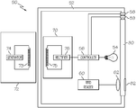
- FIG. 2 is a diagrammatic illustration showing an exemplary backlit display in accordance with aspects of the present inventive subject matter.
- FIG. 3 is a diagrammatic illustration showing an exemplary edge-lit display configuration suitable for practicing aspects of the present inventive subject matter.
- FIG. 4 is a diagrammatic illustration showing an exemplary configuration of a power supply for the display shown in FIG. 2 .
- FIG. 5 is a diagrammatic illustration showing an exemplary display configuration in accordance with aspects of the present inventive subject matter, including an optional mirror or half-mirror cover.
- FIG. 6 is a diagrammatic illustration showing an exemplary display configuration in accordance with aspects of the present inventive subject matter, including an optional shutter.
- FIG. 7 is a diagrammatic illustration showing an exemplary display configuration in accordance with aspects of the present inventive subject matter, including an optional variable information display unit.
- the display or sign holds or otherwise supports a graphic media intended to be viewed, e.g., by the public or some other desired audience.
- the graphic media is, e.g., a paper, metal foils or films, or polymeric film having a desired image printed, laminated or otherwise formed thereon.
- the image may also be formed by perforating the film or foil using different perforation sizes or patterns to create the image.
- the image may include, without limitation, text, graphics, photographic images and/or combinations of any of the foregoing.
- the graphic media may be transparent, semi-transparent or translucent.
- the image may be multi-color, black and white or otherwise monotone.
- the graphic media is selectively mounted in, on or to the display/sign, and from time-to-time can be changed as desired by a user of the display/sign. That is to say, one graphic media, e.g., having a first image printed or formed thereon, can be exchanged for another graphic media, e.g., having a second image printed or formed thereon or to inform the viewer of a change in condition, such as a sale or other promotion. That is, the image may remain the same but additional information may be provided with the original graphic.
- the display/sign can be updated or changed as desired by the user to present various different graphic media to the target audience.
- the display/sign may be used to provide advertising that a user may wish to change from time-to-time. Accordingly, rather than replacing the entire display or sign, the user merely replaces the graphic media mounted thereto or otherwise held thereby.
- the graphic media when mounted in, on or to the display or sign, the graphic media is selectively illuminated by one or more light sources.
- the display or signage may be implemented as a backlit application, a front-lit application or a side or edge-lit application.
- the light source optionally comprises a light emitting diode (LED) or a collection of multiple LEDs.
- the LEDs can be conventional LEDs or organic LEDs.
- other electroluminescent material can be employed as the light source or other conventional light sources may be employed, e.g., incandescent or fluorescent lighting.
- a plurality of light sources are provided which each emit light at a different wavelength or a single light source is provided which is capable of emitting light at a plurality of different wavelengths.
- the light source includes one or more layers or elements which produce different wavelengths of light.
- the color and/or wavelength of the illumination can therefore be selected as desired.
- the intensity of the illumination is also able to be selectively controlled.
- one or more of a variety of power sources are optionally included to provide electrical power for the display/sign, e.g., to selectively power the light source or other electronic components.
- the power source may be a solar cell or other like photovoltaic element.
- the power source may be a battery, e.g., which may be rechargeable.
- electrical power can be obtained for the display or sign via a conventional wall outlet or other like source operatively connected to an electrical mains or conventional power grid.
- electrical power is supplied to the display or signage via an equipped coil or loop of conductive wire or the like which is inductively or magnetically coupled, e.g., to an external drive circuit or the like.
- an AC (alternating current) power signal is picked up from the drive circuit by the inductively and/or magnetically coupled conductive coil or loop equipped on or in the display/sign.
- the power may be rectified and/or otherwise conditioned prior to its delivery to the light source and/or other electronic components of the display/sign.
- a rechargeable battery is employed, optionally, it may be recharged via a photovoltaic or other suitable source, e.g., such as those mentioned herein.
- the display or sign is also optionally equipped with an RFID (Radio Frequency IDentification) reader or other like communication device such as a near field communication device (NFC).
- the reader is provisioned to communicate with an RFID device carried by the graphic media.
- the RFID device carried by the graphic media is position thereon, so that when the graphic media is installed in or on the display/sign, the RFID device is sufficiently close to the reader (or an antenna thereof) to permit communication to be established between the RFID device and the reader.
- the reader may also may selectively write and/or up-load data or information to the RFID device and/or program the RFID device.
- the RFID device may be integrated on or into the media itself or it may be implemented as a label or sticker which is applied to the media.
- RFID technology it is to be appreciated that smartcard technology and/or other like technologies (e.g., that may be based on contact reading and writing of electronic information) are also contemplated and may be utilized for alternate embodiments in appropriate circumstances.
- the advantage of RFID technology and/or similar wireless communication technologies is that it provides greater freedom or leeway in the positioning of the RFID or other like device on the graphic media.
- the display and/or sign also includes a controller that regulates and/or otherwise controls operation of the display/sign.
- the controller selectively controls the light source, e.g., to turn the illumination on or off, to control or vary the color or wavelength of emitted illumination, to control or vary the intensity of the illumination, etc.
- the controller is in operative communication with and/or responsive to the reader, and accordingly controls operation of the display/sign based upon data, information and/or other communications received from the RFID device.
- the RFID device is loaded with and/or otherwise contains authentication data.
- the authentication data ensures that the graphic media is authentic or genuine.
- the controller enables operation of the display/sign.
- the controller may disable operation of the display/sign, e.g., by interrupting the delivery of electrical power to the light source or otherwise turning the light source off.
- the controller may control a magnetic or other like lock which protects against unauthorized removal or installation of media.
- the RFID device is loaded with and/or otherwise contains data or information related to illumination characteristics.
- the data or information may indicate what color, wavelength or intensity or other characteristic of illumination is desired for the particular graphic media on which the RFID device is carried. Accordingly, the reader obtains this information from the RFID device and in turn the controller regulates the light source to achieve the indicated illumination characteristics.
- the RFID device is loaded with data or information indicating suitable illumination characteristics that meet the desired criteria, e.g., the color or wavelength of the illumination, the intensity of the illumination, etc.
- the RFID device can be selectively loaded or otherwise provisioned with different data or information indicating different desired illumination characteristics. Consequently, when the media carrying the RFID device is installed in or on the display, the reader obtains the data/information and the controller regulates the light source accordingly to achieve the characteristic illumination and/or desired effects specific to the particular media installed in or on the display.
- the illumination is actively controlled and the RFID device may be provisioned with information or data indicating the desired control sequence or control options or control responses to be executed in response to detected stimuli in order to achieve a desired effect for the particular media carrying the RFID device.
- the illumination may be cycled or otherwise varied through an array of different colors or wavelengths or the intensity of the illumination may be cycled or varied through an array of different levels.
- the controller may selectively turn the illumination on and off, e.g., such that the signage is illuminated during evening or otherwise dark hours and is not illuminated during daytime or light hours, and thusly the display conserves power.
- the display may be equipped with an ambient light sensor and the controller programmed or otherwise provisioned to turn the illumination on when the detected ambient light falls below a set or otherwise determined threshold, while otherwise leaving or turning off the illumination when the detected ambient light remains or rises above the threshold.
- the intensity of the illumination from the light source can be controlled by the controller in response to the ambient lighting conditions detected by the light sensor.
- the display is optionally equipped or otherwise provisioned with a passive infrared (PIR) sensor or other motion sensor to detect the presence of individuals near the display.
- PIR passive infrared
- the controller can then operate the display in response to the detection of a nearby person or persons.
- the light source can be turned on or the illumination intensity increased when an individual or audience is detected and the light source can be turned off or the illumination intensity decreased when nobody is detected, thusly the display conserves power when it is not being viewed.
- the light source may provide illumination outside the visible wavelength, e.g., such as UV (ultraviolet) or IR (infrared) illumination.
- the graphic media may be printed with a fluorescent ink or otherwise provided with fluorescent material that glows or fluoresces in response to the foregoing illumination. In this way, the visual appeal may be enhanced and/or the appearance of motion may be provided.
- an RFID or other like device carried by the media may be programmed or otherwise provisioned to communicate with viewers' mobile phones and/or other communication devices (e.g., a personal digital assistant (PDA) or the like) carried by viewers of the display/sign, for example, using the Near Field Communication (NFC) standard or another suitable standard.
- PDA personal digital assistant
- NFC Near Field Communication
- a mobile phone or other device with an integrated NFC or like reader is placed near the RFID or other like device carried on or by the media, it will download content, e.g., relevant to the media, such as data, music or a video or a discount coupon for a product advertised by the media, etc.
- the display 50 includes a box or frame 52 which holds or otherwise supports a selectively replaceable graphic media 80 , e.g., carrying an RFID communication device 82 .
- the media 80 is mounted to or supported on or next to a major surface of a pane of glass or other like light transmitting material.
- the display 50 includes is a light source 54 that selectively illuminates the media 80 from a backside or rear thereof. That is to say, the media 80 is illuminated from the side thereof which is opposite the side of the media 80 from which the media 80 is intended to be viewed.
- the light source 54 may alternately be arranged on the front side of the media 80 or at some location along the edge of the media 80 .
- FIG. 3 shows an exemplary edge-lit configuration.
- the media 80 is supported on a first major surface of a pane of glass or other suitable light guide 90
- the light source 54 includes two sources arranged at the edges or sides of the light guide 90 .
- a light scattering and/or reflective film or laminate 92 is support on a second major surface of the light guide 90 , opposite the first major surface. Accordingly, illumination from the light source 54 is launched into the light guide 90 and in turn directed therethrough to the graphic media 80 to illuminate the media.
- the graphic media 80 is, e.g., a paper, foil or polymeric film or laminate having a desired image or content printed or otherwise formed thereon.
- the image may include, without limitation, text, graphics, photographic images and/or combinations of any of the foregoing.
- the graphic media 80 may be transparent, semi-transparent or translucent.
- the image or content may be multi-color, black and white or otherwise monotone.
- the graphic or image for the graphic may be formed by creating a pattern of perforations, holes, slits which may be of a similar or different shape.
- a printed image can be combined with a perforation pattern.
- the light source 54 has been illustrated as a single element in FIG. 2 .
- the light source 54 may in practice be composed of multiple elements or sources.
- the light source 54 optionally comprises an LED or a collection of multiple LEDs.
- the LEDs can be conventional LEDs or organic LEDs.
- other electroluminescent material can be employed as the light source 54 or other conventional light sources may be employed, e.g., incandescent or fluorescent lighting.
- a plurality of light sources are provided which each emit light of a different wavelength or color or a single light source is provided which is capable of selectively emitting light at a plurality of different wavelengths. Accordingly, by appropriate control of the light source 54 , the color and/or wavelength of the illumination can therefore be selected as desired.
- the display 50 also includes a controller 56 , an RFID reader 60 (including an antenna 62 ) and an electrical power supply 70 .
- the power supply 70 provides electrical power for the light source 54 and/or the other electronic components of the display 50 .
- the electrical power supplied to the light source 54 is regulated by the controller 56 .
- the controller 56 is able to selectively turn the light source 54 on or off, and the intensity of illumination provided from the light source 54 may also be controlled by the controller 56 .
- the controller 56 may also selectively control the color and/or wavelength of illumination provided from the light source 54 .
- the light source 54 may provide illumination outside the visible wavelength, e.g., such as UV (ultraviolet) or IR (infrared) illumination.
- the graphic media 80 may be printed with a fluorescent ink or otherwise provided with fluorescent material that glows or fluoresces in response to the foregoing illumination. In this way, the visual appeal may be enhanced and/or the appearance of motion may be provided.
- the power supply 70 is optionally implemented in one or more of a variety of different ways.
- the power source 70 may be a solar cell or other like photovoltaic element.
- the power source 70 may be a battery, e.g., which may be rechargeable.
- electrical power can be obtained for the display or sign 50 via a conventional wall outlet or other like source operatively connected to an electrical mains or conventional power grid.
- a rechargeable battery is employed, optionally, it may be recharged via a photovoltaic or other suitable source, e.g., such as those mentioned herein.
- electrical power is supplied to the display 50 , e.g., via an external drive circuit 72 or the like.
- the external drive circuit 72 may optionally include a coil or loop of conductive wire 73 driven by a generator 74 or other suitable electric power source to produce, e.g., an AC power signal.
- the power supply 70 picks-up the AC power signal with a coil or loop of conductive wire 75 or the like which is inductively or magnetically coupled to the external drive circuit 72 , e.g., via the drive circuit's coil or loop of conductive wire 73 .
- the power may be rectified (e.g., via a rectifier 76 ) and/or otherwise conditioned prior to its delivery to the light source 54 and/or other electronic components of the display/sign 50 .
- a configuration such as the exemplary configuration shown in FIG. 4 , e.g., allows the display 50 to be mounted on the outside of a wall or surface with the drive circuit 72 on the other side, or placed on top of a stand with the drive circuit 72 underneath.
- the RFID reader 60 is, as described above, operatively connected to and/or in communication with the controller 56 .
- the reader 60 may also selectively write and/or up-load data or information to the RFID device 82 and/or program the RFID device 82 .
- the display 50 additionally includes a motion sensor 58 (e.g., such as a PIR sensor) and/or an ambient light sensor 59 , either or both also being operatively connected to and/or in communication with the controller 56 .
- the RFID device 82 carried by the graphic media 80 is positioned thereon, so that when the graphic media 80 is installed in or on the display/sign 50 , the RFID device 82 is within range of the reader 60 (or the reader's antenna 62 ) to permit communication to be established between the RFID device 82 and the reader 60 .
- the RFID device 82 may be integrated on or into the media 80 itself, such as being laminated into the material or it may be implemented as a label or sticker which is applied to the media 80 .
- the label or tag may be removable from the graphic so as to allow recycling.
- the controller 56 is optionally implemented as a microprocessor or the like that regulates and/or otherwise controls operation of the display/sign 50 .
- the controller 56 selectively controls the light source 54 , e.g., to turn the illumination on or off, to control or vary the color or wavelength of emitted illumination, to control or vary the intensity of the illumination, etc.
- the controller 56 is optionally in operative communication with and/or responsive to the reader 60 , and accordingly controls operation of the display/sign 50 based upon data, information and/or other communications received from the RFID device 82 .
- the RFID device 82 is loaded with and/or otherwise contains authentication data.
- the authentication data may be an otherwise secret alphanumeric code or the like that ensures that the graphic media 80 is authentic or genuine.
- the controller 56 enables operation of the display/sign 50 .
- the controller 56 may disable operation of the display/sign 50 , e.g., by interrupting the delivery of electrical power to the light source 54 or otherwise turning the light source 54 off.
- the controller 56 may control (i.e., selectively engage or disengage) a magnetic or other like lock (not shown).
- this lock could limit access to an interior or other location or portion of the display 50 or could limit the operation of or access to manual controls, e.g., such as a master on/off or power switch.
- the RFID device 82 is loaded with and/or otherwise contains data or information related to illumination characteristics.
- this data or information may indicate what color, wavelength or intensity or other characteristic of illumination is desired for the particular graphic media 80 on which the RFID device 82 is carried. Therefore, when the media 80 carrying the RFID device 82 is installed in the display 50 , the reader 60 obtains this information from the RFID device 82 and in turn the controller 56 regulates the light source to achieve the indicated illumination characteristics.
- the RFID device 82 is loaded with data or information indicating suitable illumination characteristics that meet the desired criteria, e.g., the color or wavelength of the illumination, the intensity of the illumination, etc.
- the RFID device 82 can be selectively loaded or otherwise provisioned with different data or information indicating different desired illumination characteristics. Consequently, when the media 80 carrying the RFID device 82 is installed in or on the display 50 , the reader 60 obtains the data/information and the controller 56 regulates the light source 54 accordingly to achieve the characteristic illumination and/or desired effects specific to the particular media 80 installed in or on the display 50 .
- the illumination is optionally actively controlled and the RFID device 82 may be provisioned with information or data indicating the desired control sequence or control options or control responses to be executed in response to detected stimuli in order to achieve a desired effect for the particular media 80 carrying the RFID device 82 .
- the illumination may be cycled or otherwise varied through an array of different colors or wavelengths or the intensity of the illumination may be cycled or varied through an array of different levels.
- the controller 56 may selectively turn the illumination on and off, e.g., such that the signage is illuminated during evening or otherwise dark hours and is not illuminated during daytime or light hours, and thusly the display 50 conserves power.
- the controller 56 may be programmed or otherwise provisioned to turn the illumination on when the detected ambient light falls below a set or otherwise determined threshold, while otherwise leaving or turning off the illumination when the detected ambient light remains or rises above the threshold.
- the intensity of the illumination from the light source 54 can be controlled by the controller 56 in response to the ambient lighting conditions detected by the light sensor 59 .
- the forgoing thresholds, on/off times, etc. may be values stored in the RFID device 82 or otherwise set by the controller 56 in accordance with data obtained from the RFID device 82 .
- the RFID device and controller can be used as part of a power conversation feature as well as a security feature providing lighting during times of darkness such as at the entry of a door or the like.
- the controller 56 operates the display 50 in response to the detection of a nearby person or persons, e.g., via the motion sensor 58 .
- the light source 54 can be turned on or the illumination intensity increased when an individual or audience is detected and the light source 54 can be turned off or the illumination intensity decreased when nobody is detected, thus the display 50 conserves power when it is not being viewed.
- an RFID device 82 carried by the media 80 may be programmed or otherwise provisioned to communicate with a viewer's mobile phone and/or other communication device (e.g., a personal digital assistant (PDA) or the like), for example, using the NFC standard or another suitable standard. Accordingly, for example, when a mobile phone or other device with an integrated NFC or like reader is placed near the RFID device 82 carried on or by the media 80 , it will download content, e.g., relevant to the media, such as data, music or a video or a discount coupon for a product advertised by the media, etc.
- content e.g., relevant to the media, such as data, music or a video or a discount coupon for a product advertised by the media, etc.
- the RFID device 82 may be any conventional RFID device as is generally known in the art, e.g., including RFID receivers, transmitters and/or transponders (collectively referred to herein as RFID “devices”).
- the RFID device 82 may includes a number of components including an antenna for wirelessly transmitting and/or receiving RF (Radio Frequency) signals and analog and/or digital electronics operatively connected thereto.
- the RFID device 82 may be a so called active or semi-passive RFID device and may also include a battery or other suitable power source.
- the RFID electronics along with any operatively connected antenna and/or power source are collectively referred to as the RFID inlay. Exemplary RFID inlays are available from Avery Dennison RFID Company of Clinton, S.C.
- the electronics are implemented via an integrated circuit (IC) or microchip or other suitable electronic circuit and may include, e.g., communications electronics, data memory, control logic, etc.
- IC integrated circuit
- the IC or microchip functions to store and/or process information, modulate and/or demodulate RF signals, as well as optionally performing other specialized functions.
- the RFID reader 60 is generally used to wirelessly obtain data or information communicated from an RFID device 82 .
- the manner in which the RFID reader 60 interacts and/or communicates with the RFID device 82 generally depends on the type of RFID device.
- the RFID device 82 may be a passive device, an active device, a semi-passive device (also known as a battery-assisted or semi-active device).
- a passive RFID device actives when the RFID reader 60 is nearby to power the RFID device 82 , e.g., via wireless illumination of the RFID device 82 with an RF signal and/or electromagnetic energy from the RFID reader 60 .
- a semi-passive or active RFID device is provided with its own power source (e.g., such as a small battery or capacitor).
- the RFID device 82 responds to queries or interrogations received from the RFID reader 60 .
- the response is achieved by backscattering, load modulation and/or other like techniques that are used to manipulate the RFID reader's field.
- backscatter is used in far-field applications (i.e., where the distance between the RFID device 82 and reader 60 (or reader's antenna 62 ) is greater than approximately a few wavelengths), and alternately, load modulation is used in near-field applications (i.e., where the aforementioned distance is within approximately a few wavelengths).
- the RFID device 82 will signal or communicate its respective data or information by backscattering a carrier wave from the RFID reader 60 . That is to say, in the case of a passive RFID device, in order to retrieve information therefrom, the RFID reader 60 typically sends an excitation signal to the RFID device 82 . The excitation signal energizes the RFID device 82 which transmits the information stored therein back to the RFID reader 60 . In turn, the RFID reader 60 receives and decodes the information from the RFID device 82 .
- a passive RFID device generally has no internal power supply, although in some instances, the device can be provided with a capacitor to store energy to allow the RFID device to have enough energy to transmit the data on the chip back to the reader.
- Power for operation of a passive RFID device is provided by the energy in the form of the incoming RF signal received by the RFID device 82 from the RFID reader 60 .
- a small electrical current induced in the antenna of the RFID device 82 by the incoming RF signal provides just enough power for the IC or microchip in the RFID device 82 to power up and transmit a response.
- the antenna of the RFID device 82 is generally designed both to collect power from the incoming signal and also to transmit the outbound backscatter signal.
- a passive RFID device has the advantage of simplicity and long life (e.g., having no battery to go dead).
- the RFID device 82 may be an active RFID device, as opposed to passive one.
- an active RFID device 82 is provisioned with its own transmitter and a power source (e.g., a battery, photovoltaic cell, etc.).
- a power source e.g., a battery, photovoltaic cell, etc.
- an active RFID device employs the self-powered transmitter to broadcast a signal which communicates the information stored on the IC or microchip in the RFID device.
- an active RFID device will also use the power source to power the IC or microchip employed therein.
- the device 82 may be a semi-passive RFID device, which is similar to an active device in that it is provisioned with its own power source, but the battery or capacitor in this case may power the IC or microchip as well as to provide energy to broadcast the signal.
- the response from the semi-passive RFID device 82 is powered by means of backscattering the RF energy received from the RFID reader 60 , i.e., the energy is reflected back to the reader 60 as with passive devices.
- the battery may also serve as a power source for data storage.
- the RFID device 82 operates in one of a variety of frequency ranges including, e.g., a low frequency (LF) range (i.e., from approximately 30 kHz to approximately 300 kHz), a high frequency (HF) range (i.e., from approximately 3 MHz to approximately 30 MHz) and an ultra-high frequency (UHF) range (i.e., from approximately 300 MHz to approximately 3 GHz).
- LF low frequency
- HF high frequency
- UHF ultra-high frequency
- a passive RFID device it may optionally operate in any one of the aforementioned frequency ranges.
- a passive device 82 in a LF system, the device 82 may operate at around 124 kHz, 125 kHz or 135 kHz; in a HF system, the device 82 may operate at around 13.56 MHz; and, in a UHF system, the device 82 may use a band anywhere from 860 MHz to 960 MHz. Alternately, a passive device system may also use 2.45 GHz and other areas of the radio spectrum. If an active RFID device 82 is employed, suitably it may operate at around 455 MHz, 2.45 GHz, or 5.8 GHz, and a semi-passive device 82 may use a frequency around 2.4 GHz.
- the read range of the RFID device 82 (i.e., the range at which the RFID reader 60 can communicate with the RFID device 82 ) is generally determined by many factors, e.g., the type of device (i.e., active, passive, etc.).
- a passive LF RFID device also referred to as a LF device
- a passive HF device also referred to as a HF device
- a passive UHF RFID device also referred to as a UHF device
- One factor influencing the read range for a passive RFID device 82 is the method used to transmit data, i.e., the coupling mode between the device 82 and the reader 60 —which may optionally be inductive coupling, capacitive or radiative/propagation coupling.
- the coupling mode between the device 82 and the reader 60 which may optionally be inductive coupling, capacitive or radiative/propagation coupling.
- inductive coupling is used between the device 82 and the reader 60 .
- radiative or propagation coupling may be used between the device 82 and the reader 60 .
- the device 82 and reader 60 are typically each provisioned with a coil or loop antenna that together form an electromagnetic field therebetween.
- the device 82 draws power from the field, uses the power to run the circuitry on the device's IC or microchip and then changes the electric load on the device antenna. Consequently, the reader antenna 62 senses the change or changes in the electromagnetic field and converts these changes into data that is understood by the reader 60 or adjunct processor (e.g., the controller 56 ).
- the device 82 Because the coil/loop in the device antenna and the coil/loop in the reader antenna 62 form an electromagnetic field therebetween in order to complete the inductive coupling between the device 82 and the reader 60 , the device 82 has to be somewhat in the proximity of the reader antenna 62 .
- the reader 60 emits electromagnetic energy which illuminates the device 82 .
- the device 82 gathers the energy from the reader 60 via its antenna, and the device's IC or microchip uses the gathered energy to change the load on the device antenna and reflect back an altered signal, i.e., backscatter.
- a UHF device can optionally communicate data in a variety of different ways, e.g., it can increase the amplitude of the reflected wave sent back to the reader 60 (i.e., amplitude shift keying), shift the reflected wave so its out of phase with respect to the received wave (i.e., phase shift keying) or change the frequency of the reflected wave (i.e., frequency shift keying).
- the reader 60 picks up the backscattered signal (e.g., via antenna 62 ) and converts the altered wave into data that is understood by the reader 60 or adjunct processor (e.g., the controller 56 ).
- the coupling of the RFID device 82 to the reader 60 can be impacted by a number of factors such as any metal in the frame of the supporting structure, moisture, the material contained in the graphic (if for example a holographic foil is used in the graphic and the like.).
- the media 80 may optionally be printed and/or cut, e.g., by a print shop or the like.
- it will have the RFID device 82 mounted at certain location (e.g., in a certain corner) on the media 80 which corresponds to where the antenna 62 of the reader 60 is located in the display 50 .
- the media 80 after being loaded into the display or sign 50 will have the RFID device 82 in relatively close proximity to the reader 60 (or its antenna 62 ) such that the device is within the read range of the reader, so that they can communicate or otherwise interact.
- desired data or information e.g., authentication codes, desired illumination characteristics, etc.
- desired data or information may be written into the RFID device 82 at the print shop.
- the presently described authentication model serves a number of purposes to the benefit of various parties by ensuring that only authentic or genuine media 80 is used within a given display or sign 50 .
- a sign shop can sell a display or sign 50 which is operative as intended only in conjunction with media 80 bearing an RFID device 82 having the proper authentication data or credentials provisioned therein.
- the sign shop benefits from the repeat business of a sign purchaser or other user seeking to replace old media 80 with new media 80 that is also compatible (i.e., also bears an RFID device 82 with the proper authentication credentials) with a display or sign 50 previously purchased from the sign shop.
- the user benefits from knowing that the media 80 is genuine and/or authentic, and accordingly the quality of the media and/or its suitability for use in the display or sign 50 can be inferred.
- the RFID device 82 optionally contains one or more specific authentication codes or the like. Accordingly, when the media 80 is installed in display or sign 50 , the reader 60 will attempt to obtain one or more of the authentication codes. Suitably, any obtained codes are in turn passed to the controller 56 for verification of their authenticity. After processing the information, the controller 56 can decide if it allows the media 80 to be used (e.g., enables illumination of the media 80 or turns on the light source 54 ) or not to be used (e.g., disables illumination of the media 80 or turns off the light source 54 ). For example, the controller 56 optionally controls a relay, which regulates and/or controls the delivery of electrical power and/or current from the power supply 70 to the light source 54 .
- a relay which regulates and/or controls the delivery of electrical power and/or current from the power supply 70 to the light source 54 .
- the authentication code may be a fixed code that is specific to a particular media supplier or specific to a particular print or sign shop.
- the print or sign shop applies the RFID device to the media 80 after printing and cutting.
- the media supplier besides supplying the rolls of media may also supply the RFID devices to be used with the media.
- the reader 60 (which also optionally functions as an RFID writer) optionally erases the authentication code from RFID device 82 after it has been read once to activate, or after a period of time has elapsed and/or otherwise enable the display or sign 50 .
- the reader 60 and/or controller 56 will allow the same code to be used some limited number of times, but after that a different code is must be obtained to enable or illuminate the display or sign 50 yet a further time, or after a set or determined number of readings, a given code can be erased or deleted.
- an adhesive used to secure the RFID device 82 to the media 80 can be such that the RFID device 82 will be destroyed or damaged to the point of inoperability if one attempts to remove or peel the RFID device 82 from the media 80 upon which it was originally adhered.
- the RFID device 82 is optionally provisioned with a set date or determined time period (e.g., about a week) or other expiration criteria (e.g., which may set and/or updated by the printer or sign shop), so that the RFID device 82 or any authentication code thereon will only work or be valid prior to and/or within the bounds of the expiration criteria.
- a set date or determined time period e.g., about a week
- other expiration criteria e.g., which may set and/or updated by the printer or sign shop
- the RFID device 82 may be provisioned to wirelessly communicate and/or otherwise interact with electronic communication devices carried by viewers of the display or sign 50 or other nearby individuals.
- the display or sign 50 may selectively communicate or otherwise interact via the RFID device 82 with a NFC or similarly enabled cell phone or other like handheld device (e.g., PDA).
- a NFC or similarly enabled cell phone or other like handheld device e.g., PDA
- a viewer can just point their cell phone or the like toward the display 50 or otherwise hold it sufficiently near the device 82 , then with the RFID function, the cell phone or the like may be able to link to a website related or associated with the advertising or other content on the graphic media 80 , bring up a coupon, or perform some other desired function.
- the NFC device employed for interaction with the viewers' cell phone or other like handheld device can be a separate element or tag or label, e.g., that may be similar to but different from the device 82 that is used to authenticate the source of media 80 .
- two devices can be used, i.e., one for authentication and one for communication with viewer devices.
- a single label can be provisioned with two RFID tags or devices.
- the first tag or device i.e., device 82
- the first tag or device is used for authentication with an authentication code, and will only interact with the reader 60 in the sign or display 50 to authenticate the printing media 80 , e.g., so as to enable the sign 50 to light up.
- the second tag or device can be written to or provisioned, e.g., by a sign shop or other entity, to support NFC interaction with consumer electronics such as NFC enable cell phones. Accordingly, the second tag or device will only interact with consumer electronics.
- the content provided by the second tag or device can be SMS (Short Message Service) code or the like which is linked to or associated with the graphical content of the media 80 .
- the two tags or devices can be stuck or otherwise linked together so if somebody tries to tamper with one, the other one will stop functioning. For example, the two functions carried by two tags could be placed into one chip and one tag will be used.
- a space to write (and lock) the authentication code into a memory separate from the space used by the NFC function.
- two tags are employed, one could make a special inlay with two chips connected to the same antenna, which would difficult to forge.
- the reader 60 also optionally functions to write to the RFID device so as to up-load and/or otherwise write data or information to the RFID device 82 .
- the RFID device is optionally loaded (e.g., periodically or as otherwise desired) with usage information from the sign or display 50 .
- the reader 60 may optionally write back to the RFID device 82 carried by the media 80 how many hours the illumination has been active, the date and/or time when the media 80 was installed or removed, the number of times the display 50 was activated or the number of times the light source 54 was turned-on, the number of times the motion sensor 58 and/or the ambient light sensor 59 was tripped, etc.
- an owner or advertiser employing the sign 50 could obtain feedback about the actual operation of the sign 50 .
- feedback is reasonably related to the traffic in the vicinity of the sign 50 and/or the amount or degree of exposure the installed media 80 would have to a target audience or potential viewers.
- feedback could be used as the basis for calculating and/or accessing a usage fee or the like for the display 50 .
- a mirror or half-mirror or other like cover 100 may be arranged in front of the display or sign 50 , e.g., between a viewer and the graphic media 80 .
- a second light source 102 may also optionally be positioned on the front side of the cover 100 .
- the effective reflectivity or reflectiveness of the cover 100 may be selectively manipulated.
- the effective reflectivity or reflectiveness of the cover 100 can be maximized so that an individual viewing the display 50 perceives his own reflection, and at the other extreme (e.g., with the interior light source 54 turned on and the exterior light source 102 turned off), the effective reflectivity or reflectiveness of the cover 100 can be minimized so that an individual viewing the display 50 perceives the graphic media 80 .
- the effective reflectivity or reflectiveness of the cover 100 can be maximized so that an individual viewing the display 50 perceives his own reflection
- the other extreme e.g., with the interior light source 54 turned on and the exterior light source 102 turned off
- the effective reflectivity or reflectiveness of the cover 100 can be minimized so that an individual viewing the display 50 perceives the graphic media 80 .
- a viewer is optionally able to perceive both his reflection and the content of the graphic media 80 .
- the graphic media 80 may depict some apparel item such that the combination of the reflected image of the viewer and the image of the graphic media 80 combine to give the appearance of the viewer wearing the apparel item.
- the reflectivity or reflectiveness may optionally be manipulated in response to the motion sensor 58 detecting the presence of an individual in the proximity of the display 50 .
- the display 50 is optionally equipped with a shutter 110 (optionally an electronic shutter), e.g., arranged on the front side of the media 80 (i.e., between the media 80 and potential viewers).
- an electronic shutter may be implemented via, e.g., a transmissive LCD (liquid crystal display) panel.
- the LCD panel or shutter 110 or portions thereof are selectively darkened or closed to obscure the media 80 or corresponding portions thereof positioned behind the panel or shutter 110 .
- the media 80 or portions thereof are made selectively viewable (e.g., through the open shutter or undarkened/transmissive portions thereof) by appropriate control of the LCD panel or shutter 110 .
- the LCD panel or shutter 110 is powered by the power supply 70 or alternately it may be equipped with its own separate power supply.
- the shutter 110 may be controlled by the controller 56 in response to data or information obtained from the RFID device 82 by the reader 60 .
- the sign 50 optionally includes an alphanumeric of other like electronic display unit 120 , e.g., to output variable data or information.
- the display unit 120 is optionally implemented as an LCD or other electrophoretic display suitable for outputting variable information.
- the media 80 is optionally provisioned with an aperture or clear transmissive window 122 through which the variable information on display unit 120 can be viewed.
- the variable information display unit 120 and/or the content thereon may be controlled by the controller 56 , e.g., in response to data or information obtained from the RFID device 82 by the reader 60 .
- a single RFID device (such as the device 82 ) may optionally be provisioned with control logic or other like instructions for the operation of the sign 50 , authentication data and NFC functionality.
- control logic or other like instructions for the operation of the sign 50 , authentication data and NFC functionality.
- a plurality of separate RFID or other like devices may be employed each provisioned to carry out one or more of the foregoing functions.
- one RFID device could be provisioned with sign control logic or the like and authentication data, while a separate RFID could be provisioned to support the NFC functionality with regard to the viewers' devices.
Landscapes
- Engineering & Computer Science (AREA)
- Business, Economics & Management (AREA)
- Development Economics (AREA)
- Theoretical Computer Science (AREA)
- General Physics & Mathematics (AREA)
- Accounting & Taxation (AREA)
- Physics & Mathematics (AREA)
- Finance (AREA)
- Strategic Management (AREA)
- Entrepreneurship & Innovation (AREA)
- Game Theory and Decision Science (AREA)
- Economics (AREA)
- Marketing (AREA)
- General Business, Economics & Management (AREA)
- Illuminated Signs And Luminous Advertising (AREA)
Abstract
Description
Claims (20)
Priority Applications (1)
| Application Number | Priority Date | Filing Date | Title |
|---|---|---|---|
| US13/014,806 US10977965B2 (en) | 2010-01-29 | 2011-01-27 | Smart sign box using electronic interactions |
Applications Claiming Priority (5)
| Application Number | Priority Date | Filing Date | Title |
|---|---|---|---|
| US29960910P | 2010-01-29 | 2010-01-29 | |
| US31147310P | 2010-03-08 | 2010-03-08 | |
| US41638410P | 2010-11-23 | 2010-11-23 | |
| US42313910P | 2010-12-15 | 2010-12-15 | |
| US13/014,806 US10977965B2 (en) | 2010-01-29 | 2011-01-27 | Smart sign box using electronic interactions |
Publications (2)
| Publication Number | Publication Date |
|---|---|
| US20110307309A1 US20110307309A1 (en) | 2011-12-15 |
| US10977965B2 true US10977965B2 (en) | 2021-04-13 |
Family
ID=45096971
Family Applications (1)
| Application Number | Title | Priority Date | Filing Date |
|---|---|---|---|
| US13/014,806 Expired - Fee Related US10977965B2 (en) | 2010-01-29 | 2011-01-27 | Smart sign box using electronic interactions |
Country Status (1)
| Country | Link |
|---|---|
| US (1) | US10977965B2 (en) |
Families Citing this family (27)
| Publication number | Priority date | Publication date | Assignee | Title |
|---|---|---|---|---|
| US10977969B2 (en) | 2010-01-29 | 2021-04-13 | Avery Dennison Retail Information Services, Llc | RFID/NFC panel and/or array used in smart signage applications and method of using |
| US10977965B2 (en) | 2010-01-29 | 2021-04-13 | Avery Dennison Retail Information Services, Llc | Smart sign box using electronic interactions |
| US9462262B1 (en) | 2011-08-29 | 2016-10-04 | Amazon Technologies, Inc. | Augmented reality environment with environmental condition control |
| CN104025556B (en) | 2011-09-01 | 2018-08-10 | 艾利丹尼森公司 | Equipment, system and method for consumer's tracking |
| US8630908B2 (en) | 2011-11-02 | 2014-01-14 | Avery Dennison Corporation | Distributed point of sale, electronic article surveillance, and product information system, apparatus and method |
| TWI463458B (en) | 2012-08-17 | 2014-12-01 | 元太科技工業股份有限公司 | Display panel with wireless charging function |
| US9144139B2 (en) * | 2012-08-27 | 2015-09-22 | The Watt Stopper, Inc. | Method and apparatus for controlling light levels to save energy |
| BR112014011243B8 (en) | 2012-09-10 | 2022-08-30 | Avery Dennison Corp | METHOD FOR PAIRING AN NFC-ENABLED RFID DEVICE WITH AN OBJECT. |
| EP3214572B1 (en) | 2012-10-18 | 2020-01-29 | Avery Dennison Corporation | System and apparatus for nfc security |
| CN104471969B (en) | 2012-11-19 | 2019-07-30 | 艾利丹尼森公司 | Disabling unauthorized NFC security systems and methods |
| US20140355298A1 (en) * | 2013-05-31 | 2014-12-04 | 3M Innovative Properties Company | Adhesive lightguide with resonant circuit |
| WO2015048432A1 (en) * | 2013-09-30 | 2015-04-02 | 3M Innovative Properties Company | Apparatus for obscuring a sensing element proximate a printed graphic |
| US9605440B2 (en) * | 2014-11-06 | 2017-03-28 | Frank E. Clay | Memorial photo box |
| FI11059U1 (en) * | 2015-10-14 | 2015-12-07 | Haarnio Oy | Sign with integrated electronic circuit |
| US10283087B2 (en) * | 2016-06-15 | 2019-05-07 | Sk Planet Co., Ltd. | Digital signage device and method for operating the same |
| US11069263B2 (en) * | 2016-11-03 | 2021-07-20 | Jakayla Dixon | Systems and methods for identifying articles of clothing |
| US10716715B2 (en) | 2017-08-29 | 2020-07-21 | Hill-Rom Services, Inc. | RFID tag inlay for incontinence detection pad |
| CN112384956B (en) | 2018-05-22 | 2024-03-15 | 先讯美资电子有限责任公司 | Slim flexible label |
| US11165161B2 (en) | 2019-01-18 | 2021-11-02 | Commscope Technologies Llc | Small cell base station integrated with storefront sign |
| US12223814B2 (en) | 2019-09-16 | 2025-02-11 | Sensormatic Electronics, LLC | Security tag for textiles using conductive thread |
| US11443160B2 (en) | 2019-09-18 | 2022-09-13 | Sensormatic Electronics, LLC | Systems and methods for laser tuning and attaching RFID tags to products |
| US10783424B1 (en) | 2019-09-18 | 2020-09-22 | Sensormatic Electronics, LLC | Systems and methods for providing tags adapted to be incorporated with or in items |
| US11055588B2 (en) | 2019-11-27 | 2021-07-06 | Sensormatic Electronics, LLC | Flexible water-resistant sensor tag |
| US12524640B2 (en) | 2019-11-27 | 2026-01-13 | Sensormatic Electronics, LLC | Flexible water-resistant sensor tag |
| US11817016B2 (en) * | 2019-12-12 | 2023-11-14 | Joseph Lai | Smart door sign with integrated IOT devices and wireless signal repeaters |
| US11755874B2 (en) | 2021-03-03 | 2023-09-12 | Sensormatic Electronics, LLC | Methods and systems for heat applied sensor tag |
| US11869324B2 (en) | 2021-12-23 | 2024-01-09 | Sensormatic Electronics, LLC | Securing a security tag into an article |
Citations (362)
| Publication number | Priority date | Publication date | Assignee | Title |
|---|---|---|---|---|
| US1331136A (en) | 1918-11-01 | 1920-02-17 | Guy L Woodjard | Spring-oiler |
| US5083111A (en) | 1990-11-26 | 1992-01-21 | Sensormatic Electronics Corporation | Jamming apparatus for electronic article surveillance systems |
| EP0677887A1 (en) | 1994-04-13 | 1995-10-18 | Texas Instruments Incorporated | Built-in chip transponder with antenna circuit |
| US5485291A (en) | 1994-02-22 | 1996-01-16 | Precision Lamp, Inc. | Uniformly thin, high efficiency large area lighting panel with two facet grooves that are spaced apart and have light source facing facets with smaller slopes than the facets facing away from the light source |
| US5609059A (en) | 1994-12-19 | 1997-03-11 | The Regents Of The University Of California | Electronic multi-purpose material level sensor |
| US5641219A (en) | 1990-06-22 | 1997-06-24 | Mizobe; Tatsuji | Uniform illumination light emitting device |
| US5648613A (en) | 1994-04-05 | 1997-07-15 | Gas Research Institute | Scan assembly and method for signal discrimination |
| US5648643A (en) | 1995-06-16 | 1997-07-15 | Knowles; Terence J. | Acoustic wave touch panel with inlayed, etched arrays and method of making the panel |
| US5720123A (en) * | 1993-12-28 | 1998-02-24 | Eastman Kodak Company | Depth image object/picture frame |
| US5841350A (en) | 1997-06-27 | 1998-11-24 | Checkpoint Systems, Inc. | Electronic security tag useful in electronic article indentification and surveillance system |
| US5867017A (en) * | 1997-04-21 | 1999-02-02 | Motorola Inc. | Energy control system with remote switching |
| US5921674A (en) | 1995-07-19 | 1999-07-13 | Koczi; Wolfgang | Optical signalling device, especially for an item of clothing |
| US5944405A (en) | 1994-08-12 | 1999-08-31 | Dai Nippon Printing Co., Ltd. | Flat light source using light-diffusing sheet with projections thereon |
| US5945938A (en) | 1996-11-14 | 1999-08-31 | National University Of Singapore | RF identification transponder |
| US5947578A (en) | 1995-10-24 | 1999-09-07 | Nu-Tech & Engineering, Inc. | Back lighting device |
| FR2783960A1 (en) | 1998-09-30 | 2000-03-31 | Synergie Ingenierie Ind Sa | Roadside/underground site/airport rear lit operable display panel having frame with upper hinged opening panel and lower magnetic holding/locking mechanism transponder identification code operated. |
| US6142375A (en) | 1998-04-10 | 2000-11-07 | 3M Innovative Properties Company | Apparatus and method for the optical detection of multiple items on a platform |
| US6144264A (en) | 1999-08-23 | 2000-11-07 | Raytheon Company | High Q-factor oscillator circuit |
| US6246778B1 (en) | 1994-04-14 | 2001-06-12 | Lewis J. Moore | Product distribution verification system using encoded marks indicative of product and destination |
| US20020030992A1 (en) | 2000-05-10 | 2002-03-14 | Maxime Lefebvre | Rugged, waterproof LED array lighting system |
| US20020036622A1 (en) | 2000-09-26 | 2002-03-28 | Denny Jaeger | Method and apparatus for detecting actuation of a controller device on a touch screen |
| JP2002162918A (en) | 2000-11-28 | 2002-06-07 | Dainippon Printing Co Ltd | Poster with RF-ID tag |
| US20020154633A1 (en) * | 2000-11-22 | 2002-10-24 | Yeshik Shin | Communications architecture for storage-based devices |
| US20020159246A1 (en) * | 2001-03-21 | 2002-10-31 | Matthew Murasko | Illuminated display system |
| US20020186133A1 (en) | 2001-06-06 | 2002-12-12 | Loof Per Olof | Complete integrated self-checkout system and method |
| US20020190845A1 (en) | 1999-08-09 | 2002-12-19 | Micron Technology, Inc. | RFID material tracking method and apparatus |
| US20030029918A1 (en) | 2001-08-09 | 2003-02-13 | Leanheart Stephen J. | Display apparatus |
| US20030034985A1 (en) | 2001-08-14 | 2003-02-20 | Needham Riddle George Herbert | Color display device |
| US20030115096A1 (en) * | 2001-12-17 | 2003-06-19 | Reynolds Randy B. | Computer-controlled, remotely programmed at-shelf advertising system |
| EP1127469B1 (en) | 1998-11-04 | 2003-07-30 | Checkpoint Systems, Inc. | Rfid tag having parallel resonant circuit for magnetically decoupling tag from its environment |
| US20040012486A1 (en) | 2002-06-04 | 2004-01-22 | Stmicroelectronics Sa | Anti-collision method for contactless electronic module |
| US6744367B1 (en) | 1999-05-22 | 2004-06-01 | Marconi Data Systems Limited | Identification tag |
| US6771256B1 (en) | 1999-10-14 | 2004-08-03 | Igraphics, Llc | Remotely programmable control device for use in electroluminescent display and lighting applications |
| US6786626B2 (en) | 2002-05-09 | 2004-09-07 | Pixon Technologies Corp. | Linear light source device for image reading |
| US20040183742A1 (en) | 2003-02-10 | 2004-09-23 | Goff Edward D. | Multi-loop antenna for radio frequency identification (RFID) communication |
| US20040220860A1 (en) | 2002-12-20 | 2004-11-04 | Michael Persky | Self-checkout system having integrated RFID reader |
| US6839035B1 (en) | 2003-10-07 | 2005-01-04 | A.C.C. Systems | Magnetically coupled antenna range extender |
| US6838989B1 (en) | 1999-12-22 | 2005-01-04 | Intermec Ip Corp. | RFID transponder having active backscatter amplifier for re-transmitting a received signal |
| US20050017071A1 (en) | 2003-07-22 | 2005-01-27 | International Business Machines Corporation | System & method of deterring theft of consumers using portable personal shopping solutions in a retail environment |
| US6851999B2 (en) | 2002-10-04 | 2005-02-08 | Peter Sui Lun Fong | Interactive LED device |
| US20050186902A1 (en) | 2004-02-20 | 2005-08-25 | Lieffort Seth A. | Field-shaping shielding for radio frequency identification (RFID) system |
| US20050207823A1 (en) | 2004-03-20 | 2005-09-22 | Hewlett-Packard Development Co., L.P. | Digital pen and a method of storing digital records of the use made of the digital pen |
| US6965205B2 (en) | 1997-08-26 | 2005-11-15 | Color Kinetics Incorporated | Light emitting diode based products |
| US20050280631A1 (en) * | 2004-06-17 | 2005-12-22 | Microsoft Corporation | Mediacube |
| JP2006011422A (en) | 2004-05-28 | 2006-01-12 | Toppan Printing Co Ltd | Bulletin board system |
| JP2006030882A (en) | 2004-07-21 | 2006-02-02 | Hitachi Ltd | Information display operation terminal |
| JP2006030883A (en) | 2004-07-21 | 2006-02-02 | Hitachi Omron Terminal Solutions Corp | Information providing system and method |
| US20060028822A1 (en) | 2004-08-09 | 2006-02-09 | Tanamachi Steven W | Medical image viewing apparatus and method |
| US20060032926A1 (en) | 2004-08-13 | 2006-02-16 | Fujitsu Limited | Radio frequency identification (RFID) tag and manufacturing method thereof |
| CN1741862A (en) | 2002-12-02 | 2006-03-01 | 艾弗芮丹尼逊有限公司 | Method for labeling fabrics and heat-transfer label well-suited for use in said method cross-reference to related applications |
| JP2006058435A (en) | 2004-08-18 | 2006-03-02 | Dainippon Printing Co Ltd | Advertisement display |
| US7012544B2 (en) | 2003-04-09 | 2006-03-14 | Cube Investments Limited | Address and/or alarm indicator sign |
| WO2006031824A2 (en) | 2004-09-14 | 2006-03-23 | Adasa, Inc. | Systems and methods for deployment and recycling of rfid tags, wireless sensors, and the containers attached thereto |
| US20060066453A1 (en) | 2004-08-16 | 2006-03-30 | Ramin Homanfar | RFID transducer alignment system |
| US20060071778A1 (en) | 2004-09-27 | 2006-04-06 | Nokia Corporation | Methods, systems, devices and computer program products for providing dynamic product information in short-range communication |
| US20060090384A1 (en) | 2003-11-20 | 2006-05-04 | Woodruff Michael A | Illuminated display device |
| US7046160B2 (en) | 2000-11-15 | 2006-05-16 | Pederson John C | LED warning light and communication system |
| US7064498B2 (en) | 1997-08-26 | 2006-06-20 | Color Kinetics Incorporated | Light-emitting diode based products |
| US20060160488A1 (en) | 2005-01-17 | 2006-07-20 | Sony Ericsson Mobile Communications Japan, Inc. | Short-range wireless communication apparatus and cellular phone terminal |
| US7084769B2 (en) | 2002-01-09 | 2006-08-01 | Vue Technology, Inc. | Intelligent station using multiple RF antennae and inventory control system and method incorporating same |
| US7086587B2 (en) | 2004-12-16 | 2006-08-08 | International Business Machines Corporation | Anti-tracking system to ensure consumer privacy |
| US7086769B1 (en) | 2004-09-09 | 2006-08-08 | Identity Group, Inc. | LED signage device |
| US7098794B2 (en) | 2004-04-30 | 2006-08-29 | Kimberly-Clark Worldwide, Inc. | Deactivating a data tag for user privacy or tamper-evident packaging |
| WO2006095212A1 (en) | 2005-03-07 | 2006-09-14 | Nokia Corporation | Method and mobile terminal device including smartcard module and near field communications means |
| US7109986B2 (en) | 2003-11-19 | 2006-09-19 | Eastman Kodak Company | Illumination apparatus |
| WO2006098765A1 (en) | 2005-03-14 | 2006-09-21 | Honeywell International Inc. | Low profile direct/indirect luminaires |
| US20060214794A1 (en) | 2005-03-28 | 2006-09-28 | Chih-Hsin Wang | Secure system for tracking elements using tags |
| US20060215958A1 (en) | 2004-11-17 | 2006-09-28 | Yeo Terence E | Enhanced electroluminescent sign |
| US20060230276A1 (en) | 2005-04-07 | 2006-10-12 | Zoltan Nochta | Authentication of products using identification tags |
| WO2006111797A1 (en) * | 2005-04-20 | 2006-10-26 | Freescale Semiconductor, Inc. | Device and method for controlling a backlit display |
| WO2006111782A1 (en) | 2005-04-19 | 2006-10-26 | Nokia Corporation, | Method, device and system for controlling application launching in a mobile terminal device |
| US20060261950A1 (en) | 2005-03-29 | 2006-11-23 | Symbol Technologies, Inc. | Smart radio frequency identification (RFID) items |
| US20060261938A1 (en) | 2005-05-19 | 2006-11-23 | Lai Kin Y A | Radio Frequency Identification (RFID) system |
| US20060266824A1 (en) * | 2003-05-22 | 2006-11-30 | Winsor Nixdorf International Gmbh | Self-service checkout |
| US20060273176A1 (en) | 2005-06-03 | 2006-12-07 | Actividentity, Inc. | Blocking contactless personal security device |
| US20060287964A1 (en) | 2003-12-17 | 2006-12-21 | Brown Kerry D | Contact/contactless and magnetic-stripe data collaboration in a payment card |
| JP2006349887A (en) | 2005-06-15 | 2006-12-28 | Dainippon Printing Co Ltd | Information providing device, reader module and writer module |
| US20060290501A1 (en) | 2005-06-24 | 2006-12-28 | Visa U.S.A., Inc. | Apparatus and method to electromagnetically shield portable consumer devices |
| US20060293956A1 (en) * | 2003-12-09 | 2006-12-28 | Walker Jay S | Systems and methods for e-mail marketing via vending machines |
| US20070008140A1 (en) | 2005-06-14 | 2007-01-11 | Mikko Saarisalo | Tag multiplication |
| US20070013479A1 (en) | 2004-12-20 | 2007-01-18 | Anurag Goel | Display designs and auxiliary promotional mechanisms for electronic labels |
| US7167106B2 (en) | 2004-04-15 | 2007-01-23 | 3M Innovative Properties Company | Methods and systems utilizing a programmable sign display located in proximity to a traffic light |
| US20070022294A1 (en) | 2005-07-25 | 2007-01-25 | Silverbrook Research Pty Ltd | Method of authenticating an object |
| US20070029939A1 (en) | 2005-08-05 | 2007-02-08 | Philip Burkum | Electroluminescent sign having a coded information region |
| US20070029384A1 (en) | 2003-08-29 | 2007-02-08 | Mikoh Corporation | Radio frequency identification tag with tamper detection capability |
| JP2007034362A (en) | 2005-07-22 | 2007-02-08 | Dnp Card Service:Kk | Digital content selling system |
| US20070057791A1 (en) | 2005-04-25 | 2007-03-15 | International Business Machines Corporation | Detecting a blocker RFID tag |
| US20070056871A1 (en) | 2005-09-09 | 2007-03-15 | Medrad, Inc. | Devices, methods and applications for intelligent medical packaging |
| WO2007035835A2 (en) | 2005-09-21 | 2007-03-29 | Ilight Technologies, Inc. | Elongated illumination device having uniform light intensity distribution |
| US20070075145A1 (en) | 2003-11-27 | 2007-04-05 | Koninklijke Phillips Electronics N.V. | Jammer for tags and smart cards |
| US7202838B2 (en) | 2003-11-19 | 2007-04-10 | Eastman Kodak Company | Viewing device |
| US20070090954A1 (en) | 2005-04-14 | 2007-04-26 | Kevin Mahaffey | RFID security system and methods |
| JP2007114924A (en) | 2005-10-19 | 2007-05-10 | Matsushita Electric Ind Co Ltd | Multiple drawing device |
| US20070120772A1 (en) | 2005-11-29 | 2007-05-31 | Samsung Electronics Co., Ltd. | Display system and operation method thereof |
| WO2007064069A1 (en) | 2005-12-02 | 2007-06-07 | Hunatech Co., Ltd. | A sign apparatus equipped with an easily replaceable and non-flat type sign unit and a differential light emission type backlight unit therefor |
| US20070135112A1 (en) | 2005-12-13 | 2007-06-14 | Lessing Simon R | Method for configuring the functionality of a mobile multimedia or communication device |
| US20070145152A1 (en) * | 2005-12-28 | 2007-06-28 | Fabrice Jogand-Coulomb | Nested memory system with near field communications capability |
| US20070188483A1 (en) | 2006-01-30 | 2007-08-16 | The Samson Group, Llc | Display apparatus for outdoor signs and related system of displays and methods of use |
| US20070194879A1 (en) | 2005-05-02 | 2007-08-23 | International Business Machines Corporation | Method and device for detecting an invalid RFID tag and method for manufacturing an RFID tag |
| US20070215685A1 (en) | 2005-02-03 | 2007-09-20 | Yottamark, Inc. | System and Method of Product Identification Using a URL |
| US20070229250A1 (en) | 2006-03-28 | 2007-10-04 | Wireless Lighting Technologies, Llc | Wireless lighting |
| US20070273951A1 (en) * | 2003-09-17 | 2007-11-29 | Ribi Hans O | Flash Imaging Devices, Methods for Making and Using the Same |
| US20070274242A1 (en) | 2004-07-29 | 2007-11-29 | Kevin Lamacraft | Multi-tag emulator |
| US7304577B2 (en) | 2004-04-08 | 2007-12-04 | 3M Innovative Properties Company | Variable frequency radio frequency identification (RFID) tags |
| US20080022160A1 (en) | 2005-12-30 | 2008-01-24 | Skyetek, Inc. | Malware scanner for rfid tags |
| US20080040845A1 (en) | 2004-12-30 | 2008-02-21 | Oren Shoshan | Exhibiting Device for Advertisements |
| US20080064346A1 (en) | 2006-09-11 | 2008-03-13 | Inside Contactless | Method for connecting a contactless integrated circuit to a nfc component |
| WO2008034937A1 (en) | 2006-09-20 | 2008-03-27 | Nokia Corporation | Near field connection establishment |
| US20080079582A1 (en) | 2006-09-28 | 2008-04-03 | Sensormatic Electronics Corporation | Electronic article surveillance enabled radio frequency identification system and method |
| EP1912437A1 (en) | 2005-07-29 | 2008-04-16 | Sony Corporation | Remote control system, remote controller, and remote control method |
| EP1914631A1 (en) | 2006-10-20 | 2008-04-23 | NTT DoCoMo, Inc. | Method and apparatus for interacting with a web service |
| US20080101400A1 (en) | 2006-10-30 | 2008-05-01 | Nokia Corporation | Managing attachment of a wireless terminal to local area networks |
| US20080100443A1 (en) | 2006-10-31 | 2008-05-01 | Lukas Grunwald | RFID security system and method |
| US7375650B2 (en) | 2004-02-27 | 2008-05-20 | Teddy Yeung Man Lo | LED traffic light |
| US20080117047A1 (en) | 2006-11-16 | 2008-05-22 | Motorola, Inc. | Method and Apparatus for Tracking Items on a Conveyer Using Capacitive RFID |
| US7377421B2 (en) | 1999-05-19 | 2008-05-27 | Digimarc Corporation | Methods and systems for interacting with printed articles, such as posters |
| US7378973B2 (en) | 2005-03-29 | 2008-05-27 | Emerson & Cuming Microwave Products, Inc. | RFID tags having improved read range |
| WO2008063706A2 (en) | 2006-11-13 | 2008-05-29 | Sony Ericsson Mobile Communications Ab | Portable communication device and method for creating wishlist |
| US20080132167A1 (en) | 2006-12-01 | 2008-06-05 | Sony Ericsson Mobile Communications Ab | Multimedia Distribution Using a Near Field Communication Capable Wireless Communication Device |
| US20080136647A1 (en) | 2006-12-11 | 2008-06-12 | Symbol Technologies, Inc. | Personal rfid detector |
| US20080146148A1 (en) | 2006-12-19 | 2008-06-19 | Broadcom Corporation | System and method for using a single antenna for active and passive radio functions |
| US20080150719A1 (en) | 2006-12-20 | 2008-06-26 | Checkpoint Systems, Inc. | Eas and uhf combination tag |
| US20080162154A1 (en) | 2006-12-28 | 2008-07-03 | Fein Gene S | System and Method for Vehicle Advertising Network |
| US20080167000A1 (en) | 2007-01-09 | 2008-07-10 | Visa U.S.A. Inc. | Mobile phone payment process including threshold indicator |
| WO2008087431A1 (en) | 2007-01-18 | 2008-07-24 | Glue4 Technologies Limited | Communication system |
| EP1948995A2 (en) | 2005-11-11 | 2008-07-30 | Koninklijke Philips Electronics N.V. | A luminaire comprising leds |
| US20080183581A1 (en) | 2007-01-31 | 2008-07-31 | Bouygues Telecom, A Corporation Of France | Methods and systems for managing coupons |
| US20080191878A1 (en) | 2005-05-27 | 2008-08-14 | Gaba Holdings International, Inc. | Consumer-Centric Rfid Point of Sale Transaction System and Method |
| US20080192932A1 (en) | 2005-05-20 | 2008-08-14 | Nxp B.V. | Method of Securely Reading Data From a Transponder |
| US20080219227A1 (en) | 2007-02-23 | 2008-09-11 | Oliver Michaelis | Method and Apparatus to Create Multicast Groups Based on Proximity |
| US20080238706A1 (en) | 2005-09-20 | 2008-10-02 | David Norris Kenwright | Apparatus and Method for Proximity-Responsive Display Materials |
| US20080238610A1 (en) | 2006-09-29 | 2008-10-02 | Einar Rosenberg | Apparatus and method using near field communications |
| US20080248815A1 (en) | 2007-04-08 | 2008-10-09 | James David Busch | Systems and Methods to Target Predictive Location Based Content and Track Conversions |
| US20080255960A1 (en) | 2006-07-05 | 2008-10-16 | Martin Khang Nguyen | Managing retail transactions |
| US20080251582A1 (en) | 2006-07-05 | 2008-10-16 | Martin Khang Nguyen | Managing retail transactions |
| US20080258875A1 (en) | 2007-04-18 | 2008-10-23 | 3M Innovative Properties Company | Radio frequency identification functionality coupled to electrically conductive signage |
| US20080262928A1 (en) * | 2007-04-18 | 2008-10-23 | Oliver Michaelis | Method and apparatus for distribution and personalization of e-coupons |
| WO2008132269A1 (en) | 2007-04-26 | 2008-11-06 | Nokia Corporation | Short range communication |
| US20080276507A1 (en) * | 2007-05-11 | 2008-11-13 | Hines Stephen P | Lighted signage using reflected light behind the signage |
| WO2008142455A2 (en) | 2007-05-24 | 2008-11-27 | Asim Bucuk | A method and system for the creation, management and authentication of links between entities |
| US20080300985A1 (en) * | 2007-05-31 | 2008-12-04 | University Of Georgia Research Foundation, Inc. | System and Method for Providing Media Content to Physically Proximate Mobile Devices |
| US20080309463A1 (en) | 2005-12-21 | 2008-12-18 | Koninklijke Philips Electronics, N.V. | Collaborating Rfid Devices |
| US7477152B2 (en) | 2005-03-14 | 2009-01-13 | Avery Dennison Corporation | RFID application test systems and methods |
| US7490054B2 (en) * | 2002-11-21 | 2009-02-10 | Kimberly-Clark Worldwide, Inc. | RFID system and method for vending machine control |
| US7492346B2 (en) | 1999-03-12 | 2009-02-17 | Panasonic Corporation | Surface lighting device and portable terminal using the same |
| US7495576B2 (en) | 2006-07-29 | 2009-02-24 | Donald D Maskeny | Modular electronic sign and method of assigning a unique identifier to common modules of said sign |
| WO2009028203A1 (en) | 2007-08-30 | 2009-03-05 | Zybox Technologies Co., Ltd. | Information display panel |
| US20090081943A1 (en) | 2007-09-26 | 2009-03-26 | Radeum, Inc. Dba Freelinc | System and method for near field communications having local security |
| US20090085746A1 (en) | 2007-09-27 | 2009-04-02 | 3M Innovative Properties Company | Signal line structure for a radio-frequency identification system |
| US20090088077A1 (en) | 2005-04-11 | 2009-04-02 | Innovision Research & Technology Plc | Communications Apparatus |
| US7515149B2 (en) | 2004-12-17 | 2009-04-07 | Eastman Kodak Company | Display with wirelessly controlled illumination |
| US20090102748A1 (en) | 2007-10-22 | 2009-04-23 | Skyline Products, Inc. | Electronic display system |
| US20090115614A1 (en) | 2007-10-30 | 2009-05-07 | Oberthur Technologies | Authentication of an electronic tag during access to a service, associated methods and system |
| US20090118006A1 (en) | 2007-11-02 | 2009-05-07 | Bally Gaming, Inc. | Game related systems, methods, and articles that combine virtual and physical elements |
| US20090168441A1 (en) | 2007-12-27 | 2009-07-02 | Foxsemicon Integrated Technology, Inc. | Illumination device and car with same |
| US20090174556A1 (en) | 2005-10-31 | 2009-07-09 | Curio, Ltd. | Rfid protection device, and related methods |
| US7564426B2 (en) | 2001-04-30 | 2009-07-21 | Disney Enterprises, Inc. | Location sensitive display device, system, and method of providing animation sequences |
| US20090193500A1 (en) | 2008-01-30 | 2009-07-30 | Kent Griffin | Near field communication activation and authorization |
| US20090189816A1 (en) | 2008-01-30 | 2009-07-30 | Intermec Ip Corp. | Near-field and far-field antenna-assembly and devices having same |
| US20090197551A1 (en) | 2008-02-05 | 2009-08-06 | Paper Radio Llc | Billboard Receiver and Localized Broadcast System |
| US20090212919A1 (en) * | 2008-02-26 | 2009-08-27 | Avery Dennison Corporation | Rfid tag for direct and indirect food contact |
| CN201302803Y (en) | 2008-11-24 | 2009-09-02 | 中国移动通信集团广东有限公司 | Multimedia poster |
| US20090221240A1 (en) | 2008-02-29 | 2009-09-03 | Nokia Corporation | Low power device activated by an external near-field reader |
| US7600906B2 (en) | 2006-03-20 | 2009-10-13 | Avago Technologies General Ip (Singapore) Pte. Ltd. | Illumination structure comprising a flexible light guide coupled with a light source |
| US20090258678A1 (en) | 2008-04-09 | 2009-10-15 | Ven Chava | System and method for storing and retrieving multimedia messages on low-cost tags in order to facilitate contextual communications |
| US20090257242A1 (en) | 2008-04-09 | 2009-10-15 | Mark Wendman | Light-emitting devices and related methods |
| US20090267862A1 (en) | 2008-04-24 | 2009-10-29 | Sirit Technologies Inc. | Conducting radio frequency signals using multiple layers |
| US20090282859A1 (en) | 2006-04-05 | 2009-11-19 | Smartfreeze S.R.L. | System for Remotely Controlling and Monitoring a Food Refrigerator and its Content |
| US20090292816A1 (en) | 2008-05-21 | 2009-11-26 | Uniloc Usa, Inc. | Device and Method for Secured Communication |
| US20090297157A1 (en) | 2002-10-24 | 2009-12-03 | Nakagawa Laboratories, Inc. | Emergency lamp and wireless emergency lamp data transmission system |
| US20090315670A1 (en) | 2004-02-25 | 2009-12-24 | Accenture Global Services Gmbh | Rfid enabled media system and method |
| EP2143991A2 (en) | 2008-07-10 | 2010-01-13 | Koito Manufacturing Co., Ltd. | Lamp |
| US20100009627A1 (en) | 2006-12-15 | 2010-01-14 | Heikki Huomo | Nfc communicator and method of data communication |
| US20100012715A1 (en) | 2008-07-21 | 2010-01-21 | Gilbarco Inc. | System and method for pairing a bluetooth device with a point-of-sale terminal |
| US7654723B2 (en) | 2007-04-27 | 2010-02-02 | Hon Hai Precision Industry Co., Ltd. | Optical plate and backlight module using the same |
| US20100030636A1 (en) | 2008-08-01 | 2010-02-04 | Roshan Vijayshankar | Methods, systems and computer readable media for storing and redeeming electronic certificates using a wireless smart card |
| US20100026464A1 (en) | 2007-02-14 | 2010-02-04 | Nxp, B.V. | Method of processing data, electronic device and transponder |
| US20100046198A1 (en) | 2008-08-21 | 2010-02-25 | Night Moves, Llc | Flexible Backlit Display |
| US7670020B2 (en) | 2007-07-04 | 2010-03-02 | Hon Hai Precision Industry Co., Ltd. | Optical plate and backlight module using the same |
| US20100066561A1 (en) | 2006-12-05 | 2010-03-18 | Deutsche Post Ag | Sensor transponder unit and method for operating it |
| US20100066508A1 (en) | 2006-11-15 | 2010-03-18 | Tapio Jokinen | Method and arrangement for communicating by means of identifiers associated with images |
| US20100082444A1 (en) | 2008-09-30 | 2010-04-01 | Apple Inc. | Portable point of purchase user interfaces |
| US20100082485A1 (en) | 2008-09-30 | 2010-04-01 | Apple Inc. | Portable point of purchase devices and methods |
| US20100079416A1 (en) | 2008-09-29 | 2010-04-01 | Samsung Electronics Co., Ltd. | Radio frequency identification (RFID), display pixel, and display panel and display apparatus using RFID display pixel |
| US20100085774A1 (en) | 2007-04-25 | 2010-04-08 | Hyu Wan Park | Lighting device using light guide plate |
| US7695165B2 (en) | 2007-06-28 | 2010-04-13 | Hon Hai Precision Industry Co., Ltd. | Optical plate and backlight module using the same |
| EP2174457A1 (en) | 2007-07-09 | 2010-04-14 | Excem | Pseudo-differential interfacing device having a switching circuit |
| US20100107463A1 (en) | 2008-10-03 | 2010-05-06 | Tracer Image | Illuminated signboard with edge effect |
| US20100123553A1 (en) | 2008-11-19 | 2010-05-20 | 3M Innovative Properties Company | Rfid tag antenna with capacitively or inductively coupled tuning component |
| US7722172B2 (en) | 2001-08-06 | 2010-05-25 | Silverbrook Research Pty Ltd | Printing cartridge with radio frequency identification |
| US7722241B2 (en) | 2007-04-26 | 2010-05-25 | Hon Hai Precision Industry Co., Ltd. | Optical plate and backlight module using the same |
| US20100141452A1 (en) | 2008-12-10 | 2010-06-10 | Sensormatic Electronics Corporation | Method and system for deactivation of combination eas/rfid tags |
| US7737858B2 (en) | 2007-03-21 | 2010-06-15 | Logitag Systems Ltd. | System, method and kit for managing inventory |
| US20100148965A1 (en) | 2008-12-16 | 2010-06-17 | Sensormatic Electronics Corporation | Method and system for item level uhf rfid tag with low frequency power assist |
| US20100148964A1 (en) | 2008-12-12 | 2010-06-17 | Broer Dirk A | Rogue rfid detector |
| US20100161410A1 (en) | 2008-12-19 | 2010-06-24 | Gill Tulloch | Smart poster |
| US20100161434A1 (en) | 2008-12-18 | 2010-06-24 | Nathaniel Christopher Herwig | Retail checkout system and method |
| KR20100072115A (en) | 2008-12-08 | 2010-06-30 | 엘지전자 주식회사 | Mobile terminal and nfc service providing method thereof |
| US7750810B2 (en) | 2005-01-21 | 2010-07-06 | Swisscom Mobile Ag | Identification method and system and device suitable for said method and system |
| WO2010077194A1 (en) | 2008-12-29 | 2010-07-08 | Telefonaktiebolaget L M Ericsson (Publ) | Method and device for installing applications on nfc-enabled devices |
| US20100174599A1 (en) | 2009-01-05 | 2010-07-08 | Apple Inc. | System and method for providing content associated with a product or service |
| US20100172149A1 (en) | 2007-12-21 | 2010-07-08 | Altair Engineering, Inc. | Light distribution using a light emitting diode assembly |
| US7752790B1 (en) | 2007-05-03 | 2010-07-13 | Michael Daryl A | Display device |
| US20100176971A1 (en) | 2009-01-09 | 2010-07-15 | 3M Innovative Properties Company | Rfid packaging and attachment methods and devices |
| US20100188842A1 (en) | 2009-01-28 | 2010-07-29 | Ubox Ltd | Illumination Device for Paved Floor |
| US20100211431A1 (en) * | 2009-02-13 | 2010-08-19 | Lutnick Howard W | Method and apparatus for advertising on a mobile gaming device |
| WO2010095988A1 (en) | 2009-02-18 | 2010-08-26 | Telefonaktiebolaget L M Ericsson (Publ) | User authentication |
| US20100217709A1 (en) | 2008-09-22 | 2010-08-26 | Christian Aabye | Apparatus and method for preventing unauthorized access to payment application installed in contactless payment device |
| US20100216396A1 (en) | 2009-02-16 | 2010-08-26 | Rocky Anthony Fernandez | Integrated System and Method for Enabling Mobile Commerce Transactions using "Contactless Identity Modules in Mobile Handsets" |
| US20100221999A1 (en) | 2009-03-02 | 2010-09-02 | Motorola, Inc. | Method for selecting content for transfer or synchronization between devices |
| US20100231362A1 (en) | 2006-10-11 | 2010-09-16 | Patrick Smith | Multi-Mode Tags and Methods of Making and Using the Same |
| US20100241494A1 (en) | 2009-03-18 | 2010-09-23 | Pradeep Kumar | Methods, systems and computer readable media for selecting and delivering electronic value certificates using a mobile device |
| EP1792272B1 (en) | 2004-09-01 | 2010-10-06 | Avery Dennison Corporation | Rfid device with combined reactive coupler |
| EP2237519A1 (en) | 2009-03-31 | 2010-10-06 | France Telecom | Method and system for securely linking digital user's data to an NFC application running on a terminal |
| US20100255865A1 (en) | 2005-09-21 | 2010-10-07 | Amit Karmarkar | Text message including a contextual attribute of a mobile device |
| US7810983B2 (en) | 2007-04-27 | 2010-10-12 | Hon Hai Precision Industry Co., Ltd. | Optical plate and backlight module using the same |
| US20100262449A1 (en) * | 2009-04-09 | 2010-10-14 | Access Mobility, Inc. | Context based mobile marketing |
| US7817045B2 (en) | 2007-05-30 | 2010-10-19 | Onderko John C | Handling system for exception RFID labels |
| US20100265041A1 (en) | 2009-04-16 | 2010-10-21 | Powerid Ltd. | Rfid transponder |
| US20100269383A1 (en) * | 2009-04-27 | 2010-10-28 | Nifenecker Eugene C | Power management system controller |
| US20100271839A1 (en) | 2009-04-24 | 2010-10-28 | Avago Technologies Ecbu Ip (Singapore) Pte.Ltd. | Light guide display with mulitple light guide layers |
| US20100275265A1 (en) | 2009-04-27 | 2010-10-28 | Michael Stephen Fiske | System for securing transactions across insecure networks |
| US20100282849A1 (en) | 2008-01-03 | 2010-11-11 | Nxp B.V. | Transponder detection by resonance frequency reduction |
| US20100290251A1 (en) | 2009-05-14 | 2010-11-18 | Young Lighting Technology Corporation | Illumination apparatus |
| US20100294835A1 (en) | 2009-05-22 | 2010-11-25 | Nokia Corporation | Method and apparatus for managing services using reusable bearer tags |
| US20100303230A1 (en) | 2009-05-29 | 2010-12-02 | Ebay Inc. | Secure Identity Binding (SIB) |
| US20100306819A1 (en) | 2009-05-29 | 2010-12-02 | Ebay Inc. | Interactive phishing detection (ipd) |
| US20100306076A1 (en) | 2009-05-29 | 2010-12-02 | Ebay Inc. | Trusted Integrity Manager (TIM) |
| US7845823B2 (en) | 1997-08-26 | 2010-12-07 | Philips Solid-State Lighting Solutions, Inc. | Controlled lighting methods and apparatus |
| US20100311326A1 (en) | 2007-12-20 | 2010-12-09 | Koninklijke Philips Electronics N.V. | Switching between multiple coupling modes |
| US7850341B2 (en) | 2004-08-06 | 2010-12-14 | GE Lighting Solutions, LLC | Elongated LED illumination device |
| WO2010148816A1 (en) | 2009-12-17 | 2010-12-29 | 中兴通讯股份有限公司 | Method for implementing reader application of near field communication mobile terminal and device thereof |
| US7876101B2 (en) | 2004-03-08 | 2011-01-25 | New York University | Active radio frequency coil providing negative resistance for high field magnetic resonance imaging |
| WO2011010970A1 (en) | 2009-07-20 | 2011-01-27 | Austriamicrosystems Ag | Method for authentication of an rfid tag |
| US20110029777A1 (en) | 2008-04-22 | 2011-02-03 | Shingo Murakami | Bootstrap of nfc application using gba |
| WO2011020041A1 (en) | 2009-08-14 | 2011-02-17 | U.S. Pole Company, Inc. | Led optical system |
| US20110047463A1 (en) | 2009-08-24 | 2011-02-24 | Xerox Corporation | Kiosk-based automatic update of online social networking sites |
| US20110047759A1 (en) * | 2009-08-25 | 2011-03-03 | Romag Fasteners Inc. | Closures with magnetic and mechanical snap fastening and method of making the same |
| US7903103B2 (en) | 2006-01-11 | 2011-03-08 | Appleton Coated, Llc | Reusable poster holder and methods for display |
| EP2296025A2 (en) | 2009-08-28 | 2011-03-16 | General Electric Company | Apparatus for coupling between a light emitting diode and a light guide |
| US20110065383A1 (en) | 2009-09-14 | 2011-03-17 | Qualcomm Incorporated | Focused antenna, multi-purpose antenna, and methods related thereto |
| WO2011033424A1 (en) | 2009-09-21 | 2011-03-24 | Koninklijke Philips Electronics N.V. | Light emitting device comprising a light guide plate with reflective shielding with glare reduction |
| US7920050B2 (en) | 2004-07-29 | 2011-04-05 | Emc Corporation | Proxy device for enhanced privacy in an RFID system |
| EP2309431A1 (en) | 2004-12-01 | 2011-04-13 | Avery Dennison Corporation | RFID tags with modifiable operating parameters |
| US20110084814A1 (en) | 2009-10-08 | 2011-04-14 | Checkpoint Systems, Inc. | Security tag utilizing rfid reflectivity mode power rationing |
| WO2011053914A2 (en) | 2009-10-30 | 2011-05-05 | Vivotech Inc. | Methods, systems, and computer readable media for facilitating use of wireless smart devices to purchase goods or services |
| US20110112920A1 (en) | 2009-11-06 | 2011-05-12 | Mestre Patrick | Methods for risk management in payment-enabled mobile device |
| US20110114735A1 (en) | 2008-05-20 | 2011-05-19 | University Of Kent | RFID Tag |
| US20110121488A1 (en) | 2001-10-19 | 2011-05-26 | Leonard Arnold Duffy | Apparatus and method for producing structures with multiple undercut stems |
| US7961097B2 (en) | 2006-12-07 | 2011-06-14 | Psion Teklogix, Inc. | RFID based monitoring system and method |
| US7959326B2 (en) | 2008-06-13 | 2011-06-14 | Philips Electronics Ltd | Orientable lens for a LED fixture |
| US20110149596A1 (en) | 2009-12-21 | 2011-06-23 | Fu Zhun Precision Industry (Shen Zhen) Co., Ltd. | Led lamp having light guide |
| US20110149079A1 (en) | 2009-12-22 | 2011-06-23 | Noel Wayne Anderson | Portal management |
| US20110156640A1 (en) | 2009-12-25 | 2011-06-30 | Mehran Moshfeghi | Method and apparatus for wirelessly transferring power and communicating with one or more slave devices |
| US20110165859A1 (en) | 2010-01-04 | 2011-07-07 | Alcatel-Lucent Usa Inc. | Interactive id system using mobile devices |
| WO2011088190A2 (en) | 2010-01-15 | 2011-07-21 | Edward Lawrence Sinofsky | Lightweight solid state lighting panel |
| WO2011094384A1 (en) | 2010-01-29 | 2011-08-04 | Avery Dennison Corporation | Smart sign box using electronic interactions |
| US20110187558A1 (en) | 2010-01-29 | 2011-08-04 | Patrick Serex | Method and system for improved traffic signage |
| US20110191478A1 (en) | 2010-01-29 | 2011-08-04 | International Business Organization Name Machines Corporation | Quick access display |
| US20110195748A1 (en) | 2010-02-09 | 2011-08-11 | Jonathan Main | Enhanced security feature for payment-enabled mobile telephone |
| US20110211344A1 (en) | 2008-08-08 | 2011-09-01 | Xicato, Inc. | Color Tunable Light Source |
| US8014722B2 (en) | 2005-06-23 | 2011-09-06 | Microsoft Corporation | Provisioning of wireless connectivity for devices using NFC |
| WO2011109092A2 (en) | 2010-03-03 | 2011-09-09 | Cree, Inc. | Led lamp with remote phosphor and diffuser configuration |
| US8018345B2 (en) | 2005-09-08 | 2011-09-13 | Sri International | RFID tags having ferromagnetic patches |
| WO2011112778A1 (en) | 2010-03-10 | 2011-09-15 | Global Standard Financial, Inc | Electronic lockbox using digitally originated checks |
| US20110225421A1 (en) | 2010-03-12 | 2011-09-15 | Samsung Electronics Co., Ltd | Method of obtaining content for mobile terminal, mobile terminal using the method, and near field communication system having the mobile terminal |
| EP2366937A1 (en) | 2010-03-18 | 2011-09-21 | GLP German Light Products GmbH | Illumination apparatus |
| US20110228517A1 (en) | 2008-11-19 | 2011-09-22 | Rohm Co., Ltd. | Led lamp |
| US20110227507A1 (en) | 2010-03-18 | 2011-09-22 | Glp German Light Products Gmbh | Illumination apparatus |
| US20110227487A1 (en) | 2007-10-09 | 2011-09-22 | Flex Lighting Ii, Llc | Light emitting display with light mixing within a film |
| US20110234379A1 (en) | 2009-08-18 | 2011-09-29 | Aq Co., Ltd. | Automatic transmission apparatus and method of automatic-transmitting signal between efid tag and mobile terminal in the same |
| US20110235318A1 (en) | 2010-03-26 | 2011-09-29 | Altair Engineering, Inc. | Led light tube with dual sided light distribution |
| US20110238995A1 (en) | 2010-03-29 | 2011-09-29 | Motorola, Inc. | Methods for authentication using near-field |
| US20110244799A1 (en) | 2010-03-31 | 2011-10-06 | Roberts David A | Systems and methods for operating transaction terminals |
| WO2011121488A1 (en) | 2010-03-31 | 2011-10-06 | Koninklijke Philips Electronics N.V. | Lighting system and light source unit for such a system |
| US20110258443A1 (en) | 2010-04-19 | 2011-10-20 | Vodafone Holding Gmbh | User authentication in a tag-based service |
| US20110285511A1 (en) | 2009-06-12 | 2011-11-24 | Impinji, Inc. | Dual-frequency rfid tag with isolated inputs |
| US8068011B1 (en) | 2010-08-27 | 2011-11-29 | Q Street, LLC | System and method for interactive user-directed interfacing between handheld devices and RFID media |
| US20110295108A1 (en) | 2007-11-26 | 2011-12-01 | C.R. Bard, Inc. | Apparatus for use with needle insertion guidance system |
| US20110307309A1 (en) | 2010-01-29 | 2011-12-15 | Avery Dennison Corporation | Smart Sign Box Using Electronic Interactions |
| US20110320314A1 (en) | 2010-04-01 | 2011-12-29 | Brown Kerry D | Optical contact loaded magnetic card |
| US20110320345A1 (en) | 2010-06-29 | 2011-12-29 | Ebay, Inc. | Smart wallet |
| US20110320291A1 (en) | 2010-06-28 | 2011-12-29 | Coon Jonathan C | Systems and methods for asynchronous mobile authorization of credit card purchases |
| US20120001725A1 (en) | 2010-06-30 | 2012-01-05 | Mstar Semiconductor, Inc. | Identification Processing Apparatus and Mobile Device Using the Same |
| US20120011572A1 (en) | 2010-07-08 | 2012-01-12 | Inside Secure | Method of performing a secure application in an nfc device |
| US20120013448A1 (en) | 2004-11-30 | 2012-01-19 | Xatra Fund Mx, Llc | System and method for enhanced rfid instrument security |
| US8102797B2 (en) | 2006-08-17 | 2012-01-24 | Microsoft Corporation | Web format-based wireless communications |
| US20120024951A1 (en) | 2004-08-04 | 2012-02-02 | Nxp B.V. | Passenger transporting system and method for obtaining tickets in such a system |
| US20120029990A1 (en) | 2007-12-13 | 2012-02-02 | Blaze Mobile | Social Media Marketing Based on Transactions Using a Mobile Device and Associated Secure Element |
| US8112066B2 (en) | 2009-06-22 | 2012-02-07 | Mourad Ben Ayed | System for NFC authentication based on BLUETOOTH proximity |
| US20120032632A1 (en) | 2010-08-06 | 2012-02-09 | Soar Roger J | Inductive transmission of power and data through ceramic armor panels |
| US8117445B2 (en) | 2006-12-20 | 2012-02-14 | Spansion Llc | Near field communication, security and non-volatile memory integrated sub-system for embedded portable applications |
| US20120039472A1 (en) | 2009-04-30 | 2012-02-16 | Jing Liu | Method and device for establishing a security mechanism for an air interface link |
| US20120059741A1 (en) | 2010-08-27 | 2012-03-08 | Mohammad Khan | Methods, systems, and computer readable media for detecting customer presence to initiate the ordering and purchase of goods and services |
| US20120055998A1 (en) | 2010-09-07 | 2012-03-08 | Stefan Mieslinger | RFID Label With Shielding Element |
| US20120061465A1 (en) | 2010-09-14 | 2012-03-15 | Icon Minsky Luo | Near field communication device, authentication system using the same and authentication method thereof |
| US20120072979A1 (en) | 2010-02-09 | 2012-03-22 | Interdigital Patent Holdings, Inc. | Method And Apparatus For Trusted Federated Identity |
| WO2012037255A2 (en) | 2010-09-14 | 2012-03-22 | Vivotech Inc. | Methods, systems, and computer readable media for secure near field communication of a non-secure memory element payload |
| US20120075148A1 (en) | 2009-06-10 | 2012-03-29 | Lg Innotek Co, Ltd. | NFC Antenna Using Dual Resonance |
| US20120083205A1 (en) | 2010-10-04 | 2012-04-05 | Qualcomm Incorporated | Nfc device having a differential input envelope detector |
| US20120089845A1 (en) | 2009-01-28 | 2012-04-12 | Raleigh Gregory G | Verifiable device assisted service usage billing with integrated accounting, mediation accounting, and multi-account |
| US20120126700A1 (en) | 2010-11-18 | 2012-05-24 | Mayfield Jerrold W | Integrated Exit Signs and Monitoring System |
| US20120135839A1 (en) | 2010-11-30 | 2012-05-31 | Jatco Ltd | Controller of vehicle and control method of vehicle |
| US20120156992A1 (en) | 2010-12-21 | 2012-06-21 | Research In Motion Limited | Communications device including radio frequency (rf) signal blocking layer for near-field communication (nfc) device and related methods |
| US20120154633A1 (en) * | 2009-12-04 | 2012-06-21 | Rodriguez Tony F | Linked Data Methods and Systems |
| US8237562B1 (en) | 2007-11-19 | 2012-08-07 | Impinj, Inc. | Dealing with rogue RFID readers using tag identifiers |
| US8242893B1 (en) | 2008-07-01 | 2012-08-14 | Kemflo International Co., Ltd. | Filter assembly with RFID |
| CN102638446A (en) | 2011-02-10 | 2012-08-15 | Nxp股份有限公司 | Secure smart poster |
| US8249935B1 (en) | 2007-09-27 | 2012-08-21 | Sprint Communications Company L.P. | Method and system for blocking confidential information at a point-of-sale reader from eavesdropping |
| US20120218084A1 (en) | 2011-02-25 | 2012-08-30 | Nokia Corporation | Method and apparatus for presenting printed media based on radio frequency memory tag detection |
| US20120253974A1 (en) | 2011-03-30 | 2012-10-04 | Nokia Corporation | Method and apparatus for providing memory tag-based payment methods |
| US20120253646A1 (en) | 2011-03-31 | 2012-10-04 | International Business Machines Corporation | Real time estimation of vehicle traffic |
| US20120256494A1 (en) | 2008-09-27 | 2012-10-11 | Kesler Morris P | Tunable wireless energy transfer for medical applications |
| US20120265596A1 (en) | 2007-09-06 | 2012-10-18 | Mazed Mohammad A | System and method for intelligent social commerce |
| US20120265682A1 (en) | 2011-03-04 | 2012-10-18 | Citibank, N.A. | Methods and Systems Using Contactless Card |
| US20120278676A1 (en) | 2009-09-24 | 2012-11-01 | Japan Nus Co., Ltd | Rfid tag, tag reader/writer, data management system and data management method |
| US20120297204A1 (en) | 2011-05-16 | 2012-11-22 | Broadcom Corporation | Security Architecture For Using Host Memory in the Design of A Secure Element |
| US8321922B1 (en) | 2011-09-16 | 2012-11-27 | Google Inc. | Authenticating a user of a system using near field communication |
| US8326991B2 (en) | 2007-08-21 | 2012-12-04 | International Business Machines Corporation | Maintaining RFID information for virtual machines |
| US20120309302A1 (en) | 2009-02-23 | 2012-12-06 | Motorola Mobility, Inc. | Wireless Communication Device for Providing at Least One Near Field Communication Service |
| US8332272B2 (en) | 2006-08-25 | 2012-12-11 | Blaze Mobile, Inc. | Single tap transactions using an NFC enabled mobile device |
| US20120315839A1 (en) | 2009-12-30 | 2012-12-13 | Meterlive Ltd. | Analyzing audiences at public venues |
| US20130006847A1 (en) | 2010-12-30 | 2013-01-03 | Ayman Hammad | Mixed Mode Transaction Protocol |
| US20130045679A1 (en) | 2009-12-21 | 2013-02-21 | St-Ericsson Sa | Process for performing near field communication (nfc) in an integrated circuit or package also including a fm receiver |
| US20130063008A1 (en) | 2011-09-09 | 2013-03-14 | Douglas A. Martin | Access monitoring systems for use with consumer-operated kiosks and other enclosures |
| US20130065523A1 (en) | 2011-09-14 | 2013-03-14 | Lg Electronics Inc. | Mobile terminal and method of transmitting information using the same |
| US20130106576A1 (en) | 2011-10-31 | 2013-05-02 | Mark P. Hinman | Detecting rfid tag and inhibiting skimming |
| US20130157713A1 (en) | 2007-11-29 | 2013-06-20 | Larry G. Stolarczyk | Cap-lamp and communications support system |
| US8469269B2 (en) | 2005-04-07 | 2013-06-25 | Freedom Shopping, Inc. | Self checkout kiosk and retail security system |
| US20130165041A1 (en) | 2011-12-21 | 2013-06-27 | Peter Bukovjan | Near field communication data conversion with an event-field |
| US8474700B1 (en) | 2005-12-20 | 2013-07-02 | Diebold Self-Service Systems Division Of Diebold, Incorporated | Banking machine controlled responsive to data read from data bearing records |
| US20130173455A1 (en) | 2011-12-29 | 2013-07-04 | Research In Motion Limited | Mobile communications device providing near field communication (nfc) security features and related methods |
| US20130176184A1 (en) | 2011-04-05 | 2013-07-11 | Murata Manufacturing Co., Ltd. | Wireless communication device |
| US8520695B1 (en) | 2012-04-24 | 2013-08-27 | Zetta Research and Development LLC—ForC Series | Time-slot-based system and method of inter-vehicle communication |
| US20130309965A1 (en) | 2012-05-17 | 2013-11-21 | Qualcomm Incorporated | Methods and apparatus for improving nfc rf discovery loop tuning based on device sensor measurements |
| US20130344805A1 (en) | 2012-06-25 | 2013-12-26 | Broadcom Corporation | Automatic gain control for an nfc reader demodulator |
| US20130342323A1 (en) | 2012-06-26 | 2013-12-26 | Mark P. Hinman | Rfid system with barriers and key antennas |
| US20140009268A1 (en) | 2010-11-25 | 2014-01-09 | Panasonic Corporation | Communication device |
| US8638228B2 (en) | 2007-02-02 | 2014-01-28 | Hartford Fire Insurance Company | Systems and methods for sensor-enhanced recovery evaluation |
| US8655286B2 (en) | 2011-02-25 | 2014-02-18 | Blackberry Limited | Method and apparatus for tuning a communication device |
| US20140070850A1 (en) | 2012-09-07 | 2014-03-13 | Texas Instruments Incorporated | Circuits and methods for field-based communication |
| US20140113551A1 (en) | 2012-10-22 | 2014-04-24 | Qualcomm Incorporated | Device detection using load modulation in near-field communications |
| US20140139347A1 (en) | 2012-11-19 | 2014-05-22 | Avery Dennison Corporation | NFC Tags with Proximity Detection |
| US20140145823A1 (en) | 2012-11-27 | 2014-05-29 | Assa Abloy Ab | Access control system |
| US20140152856A1 (en) | 2007-12-28 | 2014-06-05 | Panasonic Corporation | Communication device, communication system, image presentation method, and program |
| US20140229251A1 (en) | 2011-03-03 | 2014-08-14 | Life In Mobile, Inc. | Method and apparatus for presenting content in response to user inputs using dynamic intelligent profiling |
| US20140227970A1 (en) | 2013-02-12 | 2014-08-14 | Qualcomm Incorporated | Methods and apparatus for improving remote nfc device detection using an oscillator circuit |
| US20140252083A1 (en) | 2011-01-04 | 2014-09-11 | AQ Corporation | System for providing advertisement information |
| US8842102B2 (en) | 2010-11-23 | 2014-09-23 | Avery Dennison Corporation | Graphic medic display device and method for using same |
| US8880055B1 (en) | 2011-10-06 | 2014-11-04 | Marvell International Ltd. | Method and apparatus for using near field communication (NFC) to perform transactions on a mobile device |
| US20140370803A1 (en) | 2013-06-18 | 2014-12-18 | Qualcomm Incorporated | Methods and apparatus for improving remote nfc device detection using a low power oscillator circuit |
| US8937531B2 (en) | 2012-06-26 | 2015-01-20 | Eastman Kodak Company | RFID system with multiple tag transmit frequencies |
| US8961306B2 (en) | 2012-05-08 | 2015-02-24 | Igt | Feedback to player of device connection state |
| US9024763B2 (en) | 2006-03-03 | 2015-05-05 | Soheil Hamedani | Arrangement comprising an object made at least partially of metal or precious metal and an RFID identification device |
| US20150140929A1 (en) | 2009-03-20 | 2015-05-21 | Broadcom Europe Limited | Recovering Data in a Near Field Communication Apparatus |
| US9108434B2 (en) | 2007-12-18 | 2015-08-18 | Zih Corp. | RFID near-field antenna and associated systems |
| US9124442B2 (en) | 2009-06-25 | 2015-09-01 | Koninklijke Philips N.V. | Home automation system and method for controlling the same |
| US20150334521A1 (en) | 2009-04-01 | 2015-11-19 | AQ Corporation | Apparatus and method for near field communication |
| US20160283759A1 (en) | 2012-10-18 | 2016-09-29 | Avery Dennison Corporation | Method, System and Apparatus for NFC Security |
| US20170012355A1 (en) | 2015-07-08 | 2017-01-12 | Infineon Technologies Ag | Vertical ferrite antenna including pre-fabricated connection members |
| US20170302335A1 (en) | 2014-10-02 | 2017-10-19 | Sharp Kabushiki Kaisha | Control device, display device, communication terminal, medium, display control system, method for controlling control device, and control program |
| US20180049029A1 (en) | 2016-08-11 | 2018-02-15 | Qualcomm Incorporated | Intelligent remote touch for touch screen devices |
-
2011
- 2011-01-27 US US13/014,806 patent/US10977965B2/en not_active Expired - Fee Related
Patent Citations (393)
| Publication number | Priority date | Publication date | Assignee | Title |
|---|---|---|---|---|
| US1331136A (en) | 1918-11-01 | 1920-02-17 | Guy L Woodjard | Spring-oiler |
| US5641219A (en) | 1990-06-22 | 1997-06-24 | Mizobe; Tatsuji | Uniform illumination light emitting device |
| US5083111A (en) | 1990-11-26 | 1992-01-21 | Sensormatic Electronics Corporation | Jamming apparatus for electronic article surveillance systems |
| US5720123A (en) * | 1993-12-28 | 1998-02-24 | Eastman Kodak Company | Depth image object/picture frame |
| US5485291A (en) | 1994-02-22 | 1996-01-16 | Precision Lamp, Inc. | Uniformly thin, high efficiency large area lighting panel with two facet grooves that are spaced apart and have light source facing facets with smaller slopes than the facets facing away from the light source |
| US5648613A (en) | 1994-04-05 | 1997-07-15 | Gas Research Institute | Scan assembly and method for signal discrimination |
| EP0677887A1 (en) | 1994-04-13 | 1995-10-18 | Texas Instruments Incorporated | Built-in chip transponder with antenna circuit |
| US6246778B1 (en) | 1994-04-14 | 2001-06-12 | Lewis J. Moore | Product distribution verification system using encoded marks indicative of product and destination |
| US5944405A (en) | 1994-08-12 | 1999-08-31 | Dai Nippon Printing Co., Ltd. | Flat light source using light-diffusing sheet with projections thereon |
| US5609059A (en) | 1994-12-19 | 1997-03-11 | The Regents Of The University Of California | Electronic multi-purpose material level sensor |
| US5648643A (en) | 1995-06-16 | 1997-07-15 | Knowles; Terence J. | Acoustic wave touch panel with inlayed, etched arrays and method of making the panel |
| US5921674A (en) | 1995-07-19 | 1999-07-13 | Koczi; Wolfgang | Optical signalling device, especially for an item of clothing |
| US5947578A (en) | 1995-10-24 | 1999-09-07 | Nu-Tech & Engineering, Inc. | Back lighting device |
| US5945938A (en) | 1996-11-14 | 1999-08-31 | National University Of Singapore | RF identification transponder |
| US5867017A (en) * | 1997-04-21 | 1999-02-02 | Motorola Inc. | Energy control system with remote switching |
| US5841350A (en) | 1997-06-27 | 1998-11-24 | Checkpoint Systems, Inc. | Electronic security tag useful in electronic article indentification and surveillance system |
| US7064498B2 (en) | 1997-08-26 | 2006-06-20 | Color Kinetics Incorporated | Light-emitting diode based products |
| US7845823B2 (en) | 1997-08-26 | 2010-12-07 | Philips Solid-State Lighting Solutions, Inc. | Controlled lighting methods and apparatus |
| US6965205B2 (en) | 1997-08-26 | 2005-11-15 | Color Kinetics Incorporated | Light emitting diode based products |
| US6142375A (en) | 1998-04-10 | 2000-11-07 | 3M Innovative Properties Company | Apparatus and method for the optical detection of multiple items on a platform |
| FR2783960A1 (en) | 1998-09-30 | 2000-03-31 | Synergie Ingenierie Ind Sa | Roadside/underground site/airport rear lit operable display panel having frame with upper hinged opening panel and lower magnetic holding/locking mechanism transponder identification code operated. |
| EP1127469B1 (en) | 1998-11-04 | 2003-07-30 | Checkpoint Systems, Inc. | Rfid tag having parallel resonant circuit for magnetically decoupling tag from its environment |
| US7492346B2 (en) | 1999-03-12 | 2009-02-17 | Panasonic Corporation | Surface lighting device and portable terminal using the same |
| US7377421B2 (en) | 1999-05-19 | 2008-05-27 | Digimarc Corporation | Methods and systems for interacting with printed articles, such as posters |
| US6744367B1 (en) | 1999-05-22 | 2004-06-01 | Marconi Data Systems Limited | Identification tag |
| US20020190845A1 (en) | 1999-08-09 | 2002-12-19 | Micron Technology, Inc. | RFID material tracking method and apparatus |
| US6144264A (en) | 1999-08-23 | 2000-11-07 | Raytheon Company | High Q-factor oscillator circuit |
| US6771256B1 (en) | 1999-10-14 | 2004-08-03 | Igraphics, Llc | Remotely programmable control device for use in electroluminescent display and lighting applications |
| US6838989B1 (en) | 1999-12-22 | 2005-01-04 | Intermec Ip Corp. | RFID transponder having active backscatter amplifier for re-transmitting a received signal |
| US20020030992A1 (en) | 2000-05-10 | 2002-03-14 | Maxime Lefebvre | Rugged, waterproof LED array lighting system |
| US20020036622A1 (en) | 2000-09-26 | 2002-03-28 | Denny Jaeger | Method and apparatus for detecting actuation of a controller device on a touch screen |
| US7046160B2 (en) | 2000-11-15 | 2006-05-16 | Pederson John C | LED warning light and communication system |
| US20020154633A1 (en) * | 2000-11-22 | 2002-10-24 | Yeshik Shin | Communications architecture for storage-based devices |
| JP2002162918A (en) | 2000-11-28 | 2002-06-07 | Dainippon Printing Co Ltd | Poster with RF-ID tag |
| US20020159246A1 (en) * | 2001-03-21 | 2002-10-31 | Matthew Murasko | Illuminated display system |
| US7564426B2 (en) | 2001-04-30 | 2009-07-21 | Disney Enterprises, Inc. | Location sensitive display device, system, and method of providing animation sequences |
| US20020186133A1 (en) | 2001-06-06 | 2002-12-12 | Loof Per Olof | Complete integrated self-checkout system and method |
| US7722172B2 (en) | 2001-08-06 | 2010-05-25 | Silverbrook Research Pty Ltd | Printing cartridge with radio frequency identification |
| US20030029918A1 (en) | 2001-08-09 | 2003-02-13 | Leanheart Stephen J. | Display apparatus |
| US20030034985A1 (en) | 2001-08-14 | 2003-02-20 | Needham Riddle George Herbert | Color display device |
| US20110121488A1 (en) | 2001-10-19 | 2011-05-26 | Leonard Arnold Duffy | Apparatus and method for producing structures with multiple undercut stems |
| US20030115096A1 (en) * | 2001-12-17 | 2003-06-19 | Reynolds Randy B. | Computer-controlled, remotely programmed at-shelf advertising system |
| US7084769B2 (en) | 2002-01-09 | 2006-08-01 | Vue Technology, Inc. | Intelligent station using multiple RF antennae and inventory control system and method incorporating same |
| US6786626B2 (en) | 2002-05-09 | 2004-09-07 | Pixon Technologies Corp. | Linear light source device for image reading |
| US20040012486A1 (en) | 2002-06-04 | 2004-01-22 | Stmicroelectronics Sa | Anti-collision method for contactless electronic module |
| US6851999B2 (en) | 2002-10-04 | 2005-02-08 | Peter Sui Lun Fong | Interactive LED device |
| US20090297157A1 (en) | 2002-10-24 | 2009-12-03 | Nakagawa Laboratories, Inc. | Emergency lamp and wireless emergency lamp data transmission system |
| US7490054B2 (en) * | 2002-11-21 | 2009-02-10 | Kimberly-Clark Worldwide, Inc. | RFID system and method for vending machine control |
| CN1741862A (en) | 2002-12-02 | 2006-03-01 | 艾弗芮丹尼逊有限公司 | Method for labeling fabrics and heat-transfer label well-suited for use in said method cross-reference to related applications |
| US20040220860A1 (en) | 2002-12-20 | 2004-11-04 | Michael Persky | Self-checkout system having integrated RFID reader |
| US20040183742A1 (en) | 2003-02-10 | 2004-09-23 | Goff Edward D. | Multi-loop antenna for radio frequency identification (RFID) communication |
| US7012544B2 (en) | 2003-04-09 | 2006-03-14 | Cube Investments Limited | Address and/or alarm indicator sign |
| US20060266824A1 (en) * | 2003-05-22 | 2006-11-30 | Winsor Nixdorf International Gmbh | Self-service checkout |
| US20050017071A1 (en) | 2003-07-22 | 2005-01-27 | International Business Machines Corporation | System & method of deterring theft of consumers using portable personal shopping solutions in a retail environment |
| US20070029384A1 (en) | 2003-08-29 | 2007-02-08 | Mikoh Corporation | Radio frequency identification tag with tamper detection capability |
| US20070273951A1 (en) * | 2003-09-17 | 2007-11-29 | Ribi Hans O | Flash Imaging Devices, Methods for Making and Using the Same |
| US6839035B1 (en) | 2003-10-07 | 2005-01-04 | A.C.C. Systems | Magnetically coupled antenna range extender |
| US7109986B2 (en) | 2003-11-19 | 2006-09-19 | Eastman Kodak Company | Illumination apparatus |
| US7202838B2 (en) | 2003-11-19 | 2007-04-10 | Eastman Kodak Company | Viewing device |
| US20060090384A1 (en) | 2003-11-20 | 2006-05-04 | Woodruff Michael A | Illuminated display device |
| US20070075145A1 (en) | 2003-11-27 | 2007-04-05 | Koninklijke Phillips Electronics N.V. | Jammer for tags and smart cards |
| US20060293956A1 (en) * | 2003-12-09 | 2006-12-28 | Walker Jay S | Systems and methods for e-mail marketing via vending machines |
| US20060287964A1 (en) | 2003-12-17 | 2006-12-21 | Brown Kerry D | Contact/contactless and magnetic-stripe data collaboration in a payment card |
| US20050186902A1 (en) | 2004-02-20 | 2005-08-25 | Lieffort Seth A. | Field-shaping shielding for radio frequency identification (RFID) system |
| US20090315670A1 (en) | 2004-02-25 | 2009-12-24 | Accenture Global Services Gmbh | Rfid enabled media system and method |
| US7375650B2 (en) | 2004-02-27 | 2008-05-20 | Teddy Yeung Man Lo | LED traffic light |
| US7876101B2 (en) | 2004-03-08 | 2011-01-25 | New York University | Active radio frequency coil providing negative resistance for high field magnetic resonance imaging |
| US20050207823A1 (en) | 2004-03-20 | 2005-09-22 | Hewlett-Packard Development Co., L.P. | Digital pen and a method of storing digital records of the use made of the digital pen |
| US7304577B2 (en) | 2004-04-08 | 2007-12-04 | 3M Innovative Properties Company | Variable frequency radio frequency identification (RFID) tags |
| US7167106B2 (en) | 2004-04-15 | 2007-01-23 | 3M Innovative Properties Company | Methods and systems utilizing a programmable sign display located in proximity to a traffic light |
| US7098794B2 (en) | 2004-04-30 | 2006-08-29 | Kimberly-Clark Worldwide, Inc. | Deactivating a data tag for user privacy or tamper-evident packaging |
| JP2006011422A (en) | 2004-05-28 | 2006-01-12 | Toppan Printing Co Ltd | Bulletin board system |
| US20050280631A1 (en) * | 2004-06-17 | 2005-12-22 | Microsoft Corporation | Mediacube |
| JP2006030883A (en) | 2004-07-21 | 2006-02-02 | Hitachi Omron Terminal Solutions Corp | Information providing system and method |
| JP2006030882A (en) | 2004-07-21 | 2006-02-02 | Hitachi Ltd | Information display operation terminal |
| US20070274242A1 (en) | 2004-07-29 | 2007-11-29 | Kevin Lamacraft | Multi-tag emulator |
| US7920050B2 (en) | 2004-07-29 | 2011-04-05 | Emc Corporation | Proxy device for enhanced privacy in an RFID system |
| US20120024951A1 (en) | 2004-08-04 | 2012-02-02 | Nxp B.V. | Passenger transporting system and method for obtaining tickets in such a system |
| US7850341B2 (en) | 2004-08-06 | 2010-12-14 | GE Lighting Solutions, LLC | Elongated LED illumination device |
| US20060028822A1 (en) | 2004-08-09 | 2006-02-09 | Tanamachi Steven W | Medical image viewing apparatus and method |
| US20060032926A1 (en) | 2004-08-13 | 2006-02-16 | Fujitsu Limited | Radio frequency identification (RFID) tag and manufacturing method thereof |
| US20060066453A1 (en) | 2004-08-16 | 2006-03-30 | Ramin Homanfar | RFID transducer alignment system |
| JP2006058435A (en) | 2004-08-18 | 2006-03-02 | Dainippon Printing Co Ltd | Advertisement display |
| EP1792272B1 (en) | 2004-09-01 | 2010-10-06 | Avery Dennison Corporation | Rfid device with combined reactive coupler |
| US7086769B1 (en) | 2004-09-09 | 2006-08-08 | Identity Group, Inc. | LED signage device |
| WO2006031824A2 (en) | 2004-09-14 | 2006-03-23 | Adasa, Inc. | Systems and methods for deployment and recycling of rfid tags, wireless sensors, and the containers attached thereto |
| US20060080819A1 (en) | 2004-09-14 | 2006-04-20 | Mcallister Clarke W | Systems and methods for deployment and recycling of RFID tags, wireless sensors, and the containers attached thereto |
| US20060071778A1 (en) | 2004-09-27 | 2006-04-06 | Nokia Corporation | Methods, systems, devices and computer program products for providing dynamic product information in short-range communication |
| US20080094854A1 (en) | 2004-11-17 | 2008-04-24 | Fusion Optix Inc. | Dual illumination anisotropic light emitting device |
| US20060215958A1 (en) | 2004-11-17 | 2006-09-28 | Yeo Terence E | Enhanced electroluminescent sign |
| US20120013448A1 (en) | 2004-11-30 | 2012-01-19 | Xatra Fund Mx, Llc | System and method for enhanced rfid instrument security |
| EP2309431A1 (en) | 2004-12-01 | 2011-04-13 | Avery Dennison Corporation | RFID tags with modifiable operating parameters |
| US7086587B2 (en) | 2004-12-16 | 2006-08-08 | International Business Machines Corporation | Anti-tracking system to ensure consumer privacy |
| US7515149B2 (en) | 2004-12-17 | 2009-04-07 | Eastman Kodak Company | Display with wirelessly controlled illumination |
| US20070013479A1 (en) | 2004-12-20 | 2007-01-18 | Anurag Goel | Display designs and auxiliary promotional mechanisms for electronic labels |
| US20080040845A1 (en) | 2004-12-30 | 2008-02-21 | Oren Shoshan | Exhibiting Device for Advertisements |
| US20060160488A1 (en) | 2005-01-17 | 2006-07-20 | Sony Ericsson Mobile Communications Japan, Inc. | Short-range wireless communication apparatus and cellular phone terminal |
| US7750810B2 (en) | 2005-01-21 | 2010-07-06 | Swisscom Mobile Ag | Identification method and system and device suitable for said method and system |
| US20070215685A1 (en) | 2005-02-03 | 2007-09-20 | Yottamark, Inc. | System and Method of Product Identification Using a URL |
| WO2006095212A1 (en) | 2005-03-07 | 2006-09-14 | Nokia Corporation | Method and mobile terminal device including smartcard module and near field communications means |
| WO2006098765A1 (en) | 2005-03-14 | 2006-09-21 | Honeywell International Inc. | Low profile direct/indirect luminaires |
| US7477152B2 (en) | 2005-03-14 | 2009-01-13 | Avery Dennison Corporation | RFID application test systems and methods |
| US20060214794A1 (en) | 2005-03-28 | 2006-09-28 | Chih-Hsin Wang | Secure system for tracking elements using tags |
| US7378973B2 (en) | 2005-03-29 | 2008-05-27 | Emerson & Cuming Microwave Products, Inc. | RFID tags having improved read range |
| US20060261950A1 (en) | 2005-03-29 | 2006-11-23 | Symbol Technologies, Inc. | Smart radio frequency identification (RFID) items |
| US8469269B2 (en) | 2005-04-07 | 2013-06-25 | Freedom Shopping, Inc. | Self checkout kiosk and retail security system |
| US20060230276A1 (en) | 2005-04-07 | 2006-10-12 | Zoltan Nochta | Authentication of products using identification tags |
| US20090088077A1 (en) | 2005-04-11 | 2009-04-02 | Innovision Research & Technology Plc | Communications Apparatus |
| US9894468B2 (en) | 2005-04-11 | 2018-02-13 | Nxp Usa, Inc. | Apparatus for selectively coupling an energy storage device |
| US20070090954A1 (en) | 2005-04-14 | 2007-04-26 | Kevin Mahaffey | RFID security system and methods |
| WO2006111782A1 (en) | 2005-04-19 | 2006-10-26 | Nokia Corporation, | Method, device and system for controlling application launching in a mobile terminal device |
| WO2006111797A1 (en) * | 2005-04-20 | 2006-10-26 | Freescale Semiconductor, Inc. | Device and method for controlling a backlit display |
| US20070057791A1 (en) | 2005-04-25 | 2007-03-15 | International Business Machines Corporation | Detecting a blocker RFID tag |
| US20070194879A1 (en) | 2005-05-02 | 2007-08-23 | International Business Machines Corporation | Method and device for detecting an invalid RFID tag and method for manufacturing an RFID tag |
| US20060261938A1 (en) | 2005-05-19 | 2006-11-23 | Lai Kin Y A | Radio Frequency Identification (RFID) system |
| US20080192932A1 (en) | 2005-05-20 | 2008-08-14 | Nxp B.V. | Method of Securely Reading Data From a Transponder |
| US20080191878A1 (en) | 2005-05-27 | 2008-08-14 | Gaba Holdings International, Inc. | Consumer-Centric Rfid Point of Sale Transaction System and Method |
| US20060273176A1 (en) | 2005-06-03 | 2006-12-07 | Actividentity, Inc. | Blocking contactless personal security device |
| US20070008140A1 (en) | 2005-06-14 | 2007-01-11 | Mikko Saarisalo | Tag multiplication |
| JP2006349887A (en) | 2005-06-15 | 2006-12-28 | Dainippon Printing Co Ltd | Information providing device, reader module and writer module |
| US20110287718A1 (en) | 2005-06-23 | 2011-11-24 | Microsoft Corporation | Provisioning of wireless connectivity for devices using nfc |
| US8014722B2 (en) | 2005-06-23 | 2011-09-06 | Microsoft Corporation | Provisioning of wireless connectivity for devices using NFC |
| US20060290501A1 (en) | 2005-06-24 | 2006-12-28 | Visa U.S.A., Inc. | Apparatus and method to electromagnetically shield portable consumer devices |
| US20090088229A1 (en) | 2005-06-24 | 2009-04-02 | Ayman Hammad | Apparatus and method to electromagnetically shield portable consumer devices |
| WO2007002459A2 (en) | 2005-06-24 | 2007-01-04 | Visa U.S.A. Inc. | Apparatus and method to electromagnetically shield portable consumer devices |
| US20090146814A1 (en) | 2005-06-24 | 2009-06-11 | Ayman Hammad | Apparatus and method to electromagnetically shield portable consumer devices |
| CN101253750A (en) | 2005-06-24 | 2008-08-27 | 维萨美国股份有限公司 | Apparatus and method for electromagnetically shielding portable consumer devices |
| BRPI0611910A2 (en) | 2005-06-24 | 2011-02-22 | Visa Usa Inc | apparatus for shielding portable electronic consumer devices |
| JP2007034362A (en) | 2005-07-22 | 2007-02-08 | Dnp Card Service:Kk | Digital content selling system |
| US20070022294A1 (en) | 2005-07-25 | 2007-01-25 | Silverbrook Research Pty Ltd | Method of authenticating an object |
| CN101233753A (en) | 2005-07-29 | 2008-07-30 | 索尼株式会社 | Remote control system, remote controller and remote control method |
| EP1912437A1 (en) | 2005-07-29 | 2008-04-16 | Sony Corporation | Remote control system, remote controller, and remote control method |
| US20070029939A1 (en) | 2005-08-05 | 2007-02-08 | Philip Burkum | Electroluminescent sign having a coded information region |
| US8018345B2 (en) | 2005-09-08 | 2011-09-13 | Sri International | RFID tags having ferromagnetic patches |
| US20070056871A1 (en) | 2005-09-09 | 2007-03-15 | Medrad, Inc. | Devices, methods and applications for intelligent medical packaging |
| US20080238706A1 (en) | 2005-09-20 | 2008-10-02 | David Norris Kenwright | Apparatus and Method for Proximity-Responsive Display Materials |
| US7868778B2 (en) | 2005-09-20 | 2011-01-11 | David Norris Kenwright | Apparatus and method for proximity-responsive display materials |
| WO2007035835A2 (en) | 2005-09-21 | 2007-03-29 | Ilight Technologies, Inc. | Elongated illumination device having uniform light intensity distribution |
| US20100255865A1 (en) | 2005-09-21 | 2010-10-07 | Amit Karmarkar | Text message including a contextual attribute of a mobile device |
| JP2007114924A (en) | 2005-10-19 | 2007-05-10 | Matsushita Electric Ind Co Ltd | Multiple drawing device |
| US20090174556A1 (en) | 2005-10-31 | 2009-07-09 | Curio, Ltd. | Rfid protection device, and related methods |
| EP1948995A2 (en) | 2005-11-11 | 2008-07-30 | Koninklijke Philips Electronics N.V. | A luminaire comprising leds |
| US20070120772A1 (en) | 2005-11-29 | 2007-05-31 | Samsung Electronics Co., Ltd. | Display system and operation method thereof |
| WO2007064069A1 (en) | 2005-12-02 | 2007-06-07 | Hunatech Co., Ltd. | A sign apparatus equipped with an easily replaceable and non-flat type sign unit and a differential light emission type backlight unit therefor |
| US20070135112A1 (en) | 2005-12-13 | 2007-06-14 | Lessing Simon R | Method for configuring the functionality of a mobile multimedia or communication device |
| US8474700B1 (en) | 2005-12-20 | 2013-07-02 | Diebold Self-Service Systems Division Of Diebold, Incorporated | Banking machine controlled responsive to data read from data bearing records |
| US20080309463A1 (en) | 2005-12-21 | 2008-12-18 | Koninklijke Philips Electronics, N.V. | Collaborating Rfid Devices |
| US20070145152A1 (en) * | 2005-12-28 | 2007-06-28 | Fabrice Jogand-Coulomb | Nested memory system with near field communications capability |
| US20080022160A1 (en) | 2005-12-30 | 2008-01-24 | Skyetek, Inc. | Malware scanner for rfid tags |
| US7903103B2 (en) | 2006-01-11 | 2011-03-08 | Appleton Coated, Llc | Reusable poster holder and methods for display |
| US20070188483A1 (en) | 2006-01-30 | 2007-08-16 | The Samson Group, Llc | Display apparatus for outdoor signs and related system of displays and methods of use |
| US9024763B2 (en) | 2006-03-03 | 2015-05-05 | Soheil Hamedani | Arrangement comprising an object made at least partially of metal or precious metal and an RFID identification device |
| US7600906B2 (en) | 2006-03-20 | 2009-10-13 | Avago Technologies General Ip (Singapore) Pte. Ltd. | Illumination structure comprising a flexible light guide coupled with a light source |
| US20070229250A1 (en) | 2006-03-28 | 2007-10-04 | Wireless Lighting Technologies, Llc | Wireless lighting |
| US20090282859A1 (en) | 2006-04-05 | 2009-11-19 | Smartfreeze S.R.L. | System for Remotely Controlling and Monitoring a Food Refrigerator and its Content |
| US20080251582A1 (en) | 2006-07-05 | 2008-10-16 | Martin Khang Nguyen | Managing retail transactions |
| US20080255960A1 (en) | 2006-07-05 | 2008-10-16 | Martin Khang Nguyen | Managing retail transactions |
| US7495576B2 (en) | 2006-07-29 | 2009-02-24 | Donald D Maskeny | Modular electronic sign and method of assigning a unique identifier to common modules of said sign |
| US8102797B2 (en) | 2006-08-17 | 2012-01-24 | Microsoft Corporation | Web format-based wireless communications |
| US8332272B2 (en) | 2006-08-25 | 2012-12-11 | Blaze Mobile, Inc. | Single tap transactions using an NFC enabled mobile device |
| US20080064346A1 (en) | 2006-09-11 | 2008-03-13 | Inside Contactless | Method for connecting a contactless integrated circuit to a nfc component |
| WO2008034937A1 (en) | 2006-09-20 | 2008-03-27 | Nokia Corporation | Near field connection establishment |
| US20080079582A1 (en) | 2006-09-28 | 2008-04-03 | Sensormatic Electronics Corporation | Electronic article surveillance enabled radio frequency identification system and method |
| US20080238610A1 (en) | 2006-09-29 | 2008-10-02 | Einar Rosenberg | Apparatus and method using near field communications |
| US20100231362A1 (en) | 2006-10-11 | 2010-09-16 | Patrick Smith | Multi-Mode Tags and Methods of Making and Using the Same |
| EP1914631A1 (en) | 2006-10-20 | 2008-04-23 | NTT DoCoMo, Inc. | Method and apparatus for interacting with a web service |
| US20080101400A1 (en) | 2006-10-30 | 2008-05-01 | Nokia Corporation | Managing attachment of a wireless terminal to local area networks |
| US20080100443A1 (en) | 2006-10-31 | 2008-05-01 | Lukas Grunwald | RFID security system and method |
| WO2008063706A2 (en) | 2006-11-13 | 2008-05-29 | Sony Ericsson Mobile Communications Ab | Portable communication device and method for creating wishlist |
| US20100066508A1 (en) | 2006-11-15 | 2010-03-18 | Tapio Jokinen | Method and arrangement for communicating by means of identifiers associated with images |
| US20080117047A1 (en) | 2006-11-16 | 2008-05-22 | Motorola, Inc. | Method and Apparatus for Tracking Items on a Conveyer Using Capacitive RFID |
| US7756467B2 (en) | 2006-12-01 | 2010-07-13 | Sony Ericsson Mobile Communications Ab | Multimedia distribution using a near field communication capable wireless communication device |
| US20080132167A1 (en) | 2006-12-01 | 2008-06-05 | Sony Ericsson Mobile Communications Ab | Multimedia Distribution Using a Near Field Communication Capable Wireless Communication Device |
| US20100066561A1 (en) | 2006-12-05 | 2010-03-18 | Deutsche Post Ag | Sensor transponder unit and method for operating it |
| US7961097B2 (en) | 2006-12-07 | 2011-06-14 | Psion Teklogix, Inc. | RFID based monitoring system and method |
| US20080136647A1 (en) | 2006-12-11 | 2008-06-12 | Symbol Technologies, Inc. | Personal rfid detector |
| US20100009627A1 (en) | 2006-12-15 | 2010-01-14 | Heikki Huomo | Nfc communicator and method of data communication |
| US20080146148A1 (en) | 2006-12-19 | 2008-06-19 | Broadcom Corporation | System and method for using a single antenna for active and passive radio functions |
| US7979026B2 (en) | 2006-12-19 | 2011-07-12 | Broadcom Corporation | System and method for using a single antenna for active and passive radio functions |
| US20080150719A1 (en) | 2006-12-20 | 2008-06-26 | Checkpoint Systems, Inc. | Eas and uhf combination tag |
| US8117445B2 (en) | 2006-12-20 | 2012-02-14 | Spansion Llc | Near field communication, security and non-volatile memory integrated sub-system for embedded portable applications |
| US20080162154A1 (en) | 2006-12-28 | 2008-07-03 | Fein Gene S | System and Method for Vehicle Advertising Network |
| US20080167000A1 (en) | 2007-01-09 | 2008-07-10 | Visa U.S.A. Inc. | Mobile phone payment process including threshold indicator |
| WO2008087431A1 (en) | 2007-01-18 | 2008-07-24 | Glue4 Technologies Limited | Communication system |
| US20100075666A1 (en) | 2007-01-18 | 2010-03-25 | Neil Robert Garner | Communication system |
| US20080183581A1 (en) | 2007-01-31 | 2008-07-31 | Bouygues Telecom, A Corporation Of France | Methods and systems for managing coupons |
| US8638228B2 (en) | 2007-02-02 | 2014-01-28 | Hartford Fire Insurance Company | Systems and methods for sensor-enhanced recovery evaluation |
| US20100026464A1 (en) | 2007-02-14 | 2010-02-04 | Nxp, B.V. | Method of processing data, electronic device and transponder |
| US20080219227A1 (en) | 2007-02-23 | 2008-09-11 | Oliver Michaelis | Method and Apparatus to Create Multicast Groups Based on Proximity |
| US7737858B2 (en) | 2007-03-21 | 2010-06-15 | Logitag Systems Ltd. | System, method and kit for managing inventory |
| US20080248815A1 (en) | 2007-04-08 | 2008-10-09 | James David Busch | Systems and Methods to Target Predictive Location Based Content and Track Conversions |
| US20080258875A1 (en) | 2007-04-18 | 2008-10-23 | 3M Innovative Properties Company | Radio frequency identification functionality coupled to electrically conductive signage |
| US20080262928A1 (en) * | 2007-04-18 | 2008-10-23 | Oliver Michaelis | Method and apparatus for distribution and personalization of e-coupons |
| US20100085774A1 (en) | 2007-04-25 | 2010-04-08 | Hyu Wan Park | Lighting device using light guide plate |
| WO2008132269A1 (en) | 2007-04-26 | 2008-11-06 | Nokia Corporation | Short range communication |
| US7722241B2 (en) | 2007-04-26 | 2010-05-25 | Hon Hai Precision Industry Co., Ltd. | Optical plate and backlight module using the same |
| US7654723B2 (en) | 2007-04-27 | 2010-02-02 | Hon Hai Precision Industry Co., Ltd. | Optical plate and backlight module using the same |
| US7810983B2 (en) | 2007-04-27 | 2010-10-12 | Hon Hai Precision Industry Co., Ltd. | Optical plate and backlight module using the same |
| US7752790B1 (en) | 2007-05-03 | 2010-07-13 | Michael Daryl A | Display device |
| US20080276507A1 (en) * | 2007-05-11 | 2008-11-13 | Hines Stephen P | Lighted signage using reflected light behind the signage |
| WO2008142455A2 (en) | 2007-05-24 | 2008-11-27 | Asim Bucuk | A method and system for the creation, management and authentication of links between entities |
| US20100274859A1 (en) | 2007-05-24 | 2010-10-28 | Asim Bucuk | Method And System For The Creation, Management And Authentication Of Links Between Entities |
| US20110000971A1 (en) | 2007-05-30 | 2011-01-06 | Binforma Group Limited Liability Company | Handling system for exception rfid labels |
| US7817045B2 (en) | 2007-05-30 | 2010-10-19 | Onderko John C | Handling system for exception RFID labels |
| US20080300985A1 (en) * | 2007-05-31 | 2008-12-04 | University Of Georgia Research Foundation, Inc. | System and Method for Providing Media Content to Physically Proximate Mobile Devices |
| US7695165B2 (en) | 2007-06-28 | 2010-04-13 | Hon Hai Precision Industry Co., Ltd. | Optical plate and backlight module using the same |
| US7670020B2 (en) | 2007-07-04 | 2010-03-02 | Hon Hai Precision Industry Co., Ltd. | Optical plate and backlight module using the same |
| EP2174457A1 (en) | 2007-07-09 | 2010-04-14 | Excem | Pseudo-differential interfacing device having a switching circuit |
| US8326991B2 (en) | 2007-08-21 | 2012-12-04 | International Business Machines Corporation | Maintaining RFID information for virtual machines |
| WO2009028203A1 (en) | 2007-08-30 | 2009-03-05 | Zybox Technologies Co., Ltd. | Information display panel |
| US20120265596A1 (en) | 2007-09-06 | 2012-10-18 | Mazed Mohammad A | System and method for intelligent social commerce |
| US20090081943A1 (en) | 2007-09-26 | 2009-03-26 | Radeum, Inc. Dba Freelinc | System and method for near field communications having local security |
| US8249935B1 (en) | 2007-09-27 | 2012-08-21 | Sprint Communications Company L.P. | Method and system for blocking confidential information at a point-of-sale reader from eavesdropping |
| US20090085746A1 (en) | 2007-09-27 | 2009-04-02 | 3M Innovative Properties Company | Signal line structure for a radio-frequency identification system |
| US20110227487A1 (en) | 2007-10-09 | 2011-09-22 | Flex Lighting Ii, Llc | Light emitting display with light mixing within a film |
| US20090102748A1 (en) | 2007-10-22 | 2009-04-23 | Skyline Products, Inc. | Electronic display system |
| US20090115614A1 (en) | 2007-10-30 | 2009-05-07 | Oberthur Technologies | Authentication of an electronic tag during access to a service, associated methods and system |
| US20090118006A1 (en) | 2007-11-02 | 2009-05-07 | Bally Gaming, Inc. | Game related systems, methods, and articles that combine virtual and physical elements |
| US8237562B1 (en) | 2007-11-19 | 2012-08-07 | Impinj, Inc. | Dealing with rogue RFID readers using tag identifiers |
| US20110295108A1 (en) | 2007-11-26 | 2011-12-01 | C.R. Bard, Inc. | Apparatus for use with needle insertion guidance system |
| US20130157713A1 (en) | 2007-11-29 | 2013-06-20 | Larry G. Stolarczyk | Cap-lamp and communications support system |
| US20120029990A1 (en) | 2007-12-13 | 2012-02-02 | Blaze Mobile | Social Media Marketing Based on Transactions Using a Mobile Device and Associated Secure Element |
| US9108434B2 (en) | 2007-12-18 | 2015-08-18 | Zih Corp. | RFID near-field antenna and associated systems |
| US20100311326A1 (en) | 2007-12-20 | 2010-12-09 | Koninklijke Philips Electronics N.V. | Switching between multiple coupling modes |
| US20100172149A1 (en) | 2007-12-21 | 2010-07-08 | Altair Engineering, Inc. | Light distribution using a light emitting diode assembly |
| US20090168441A1 (en) | 2007-12-27 | 2009-07-02 | Foxsemicon Integrated Technology, Inc. | Illumination device and car with same |
| US20140152856A1 (en) | 2007-12-28 | 2014-06-05 | Panasonic Corporation | Communication device, communication system, image presentation method, and program |
| US20100282849A1 (en) | 2008-01-03 | 2010-11-11 | Nxp B.V. | Transponder detection by resonance frequency reduction |
| US20090193500A1 (en) | 2008-01-30 | 2009-07-30 | Kent Griffin | Near field communication activation and authorization |
| US20090189816A1 (en) | 2008-01-30 | 2009-07-30 | Intermec Ip Corp. | Near-field and far-field antenna-assembly and devices having same |
| US20090192937A1 (en) | 2008-01-30 | 2009-07-30 | Kent Griffin | Two step near field communication transactions |
| US20090197551A1 (en) | 2008-02-05 | 2009-08-06 | Paper Radio Llc | Billboard Receiver and Localized Broadcast System |
| US20090212919A1 (en) * | 2008-02-26 | 2009-08-27 | Avery Dennison Corporation | Rfid tag for direct and indirect food contact |
| US20090221240A1 (en) | 2008-02-29 | 2009-09-03 | Nokia Corporation | Low power device activated by an external near-field reader |
| US20090258678A1 (en) | 2008-04-09 | 2009-10-15 | Ven Chava | System and method for storing and retrieving multimedia messages on low-cost tags in order to facilitate contextual communications |
| US20090257242A1 (en) | 2008-04-09 | 2009-10-15 | Mark Wendman | Light-emitting devices and related methods |
| US20110029777A1 (en) | 2008-04-22 | 2011-02-03 | Shingo Murakami | Bootstrap of nfc application using gba |
| US20090267862A1 (en) | 2008-04-24 | 2009-10-29 | Sirit Technologies Inc. | Conducting radio frequency signals using multiple layers |
| US20110114735A1 (en) | 2008-05-20 | 2011-05-19 | University Of Kent | RFID Tag |
| US20090292816A1 (en) | 2008-05-21 | 2009-11-26 | Uniloc Usa, Inc. | Device and Method for Secured Communication |
| US7959326B2 (en) | 2008-06-13 | 2011-06-14 | Philips Electronics Ltd | Orientable lens for a LED fixture |
| US8242893B1 (en) | 2008-07-01 | 2012-08-14 | Kemflo International Co., Ltd. | Filter assembly with RFID |
| EP2143991A2 (en) | 2008-07-10 | 2010-01-13 | Koito Manufacturing Co., Ltd. | Lamp |
| US20100012715A1 (en) | 2008-07-21 | 2010-01-21 | Gilbarco Inc. | System and method for pairing a bluetooth device with a point-of-sale terminal |
| US20100030636A1 (en) | 2008-08-01 | 2010-02-04 | Roshan Vijayshankar | Methods, systems and computer readable media for storing and redeeming electronic certificates using a wireless smart card |
| US20110211344A1 (en) | 2008-08-08 | 2011-09-01 | Xicato, Inc. | Color Tunable Light Source |
| US20100046198A1 (en) | 2008-08-21 | 2010-02-25 | Night Moves, Llc | Flexible Backlit Display |
| US20100217709A1 (en) | 2008-09-22 | 2010-08-26 | Christian Aabye | Apparatus and method for preventing unauthorized access to payment application installed in contactless payment device |
| US20120256494A1 (en) | 2008-09-27 | 2012-10-11 | Kesler Morris P | Tunable wireless energy transfer for medical applications |
| US20100079416A1 (en) | 2008-09-29 | 2010-04-01 | Samsung Electronics Co., Ltd. | Radio frequency identification (RFID), display pixel, and display panel and display apparatus using RFID display pixel |
| US20100082485A1 (en) | 2008-09-30 | 2010-04-01 | Apple Inc. | Portable point of purchase devices and methods |
| US20100082444A1 (en) | 2008-09-30 | 2010-04-01 | Apple Inc. | Portable point of purchase user interfaces |
| US20100107463A1 (en) | 2008-10-03 | 2010-05-06 | Tracer Image | Illuminated signboard with edge effect |
| US20110228517A1 (en) | 2008-11-19 | 2011-09-22 | Rohm Co., Ltd. | Led lamp |
| US20100123553A1 (en) | 2008-11-19 | 2010-05-20 | 3M Innovative Properties Company | Rfid tag antenna with capacitively or inductively coupled tuning component |
| CN201302803Y (en) | 2008-11-24 | 2009-09-02 | 中国移动通信集团广东有限公司 | Multimedia poster |
| KR20100072115A (en) | 2008-12-08 | 2010-06-30 | 엘지전자 주식회사 | Mobile terminal and nfc service providing method thereof |
| US20100141452A1 (en) | 2008-12-10 | 2010-06-10 | Sensormatic Electronics Corporation | Method and system for deactivation of combination eas/rfid tags |
| US20100148964A1 (en) | 2008-12-12 | 2010-06-17 | Broer Dirk A | Rogue rfid detector |
| US20100148965A1 (en) | 2008-12-16 | 2010-06-17 | Sensormatic Electronics Corporation | Method and system for item level uhf rfid tag with low frequency power assist |
| US20100161434A1 (en) | 2008-12-18 | 2010-06-24 | Nathaniel Christopher Herwig | Retail checkout system and method |
| US8126505B2 (en) | 2008-12-19 | 2012-02-28 | Ncr Corporation | Data verification system for a near field communications enabled display |
| US20100161410A1 (en) | 2008-12-19 | 2010-06-24 | Gill Tulloch | Smart poster |
| EP2371110A1 (en) | 2008-12-29 | 2011-10-05 | Telefonaktiebolaget L M Ericsson (publ) | Method and device for installing applications on nfc-enabled devices |
| WO2010077194A1 (en) | 2008-12-29 | 2010-07-08 | Telefonaktiebolaget L M Ericsson (Publ) | Method and device for installing applications on nfc-enabled devices |
| US20110276961A1 (en) | 2008-12-29 | 2011-11-10 | Telefonaktiebolaget Lm Ericsson (Publ) | Method and Device for Installing Applications on NFC-Enabled Devices |
| US20100174599A1 (en) | 2009-01-05 | 2010-07-08 | Apple Inc. | System and method for providing content associated with a product or service |
| US20100176971A1 (en) | 2009-01-09 | 2010-07-15 | 3M Innovative Properties Company | Rfid packaging and attachment methods and devices |
| US20120089845A1 (en) | 2009-01-28 | 2012-04-12 | Raleigh Gregory G | Verifiable device assisted service usage billing with integrated accounting, mediation accounting, and multi-account |
| US20100188842A1 (en) | 2009-01-28 | 2010-07-29 | Ubox Ltd | Illumination Device for Paved Floor |
| US20100211431A1 (en) * | 2009-02-13 | 2010-08-19 | Lutnick Howard W | Method and apparatus for advertising on a mobile gaming device |
| US20100216396A1 (en) | 2009-02-16 | 2010-08-26 | Rocky Anthony Fernandez | Integrated System and Method for Enabling Mobile Commerce Transactions using "Contactless Identity Modules in Mobile Handsets" |
| WO2010095988A1 (en) | 2009-02-18 | 2010-08-26 | Telefonaktiebolaget L M Ericsson (Publ) | User authentication |
| US20120309302A1 (en) | 2009-02-23 | 2012-12-06 | Motorola Mobility, Inc. | Wireless Communication Device for Providing at Least One Near Field Communication Service |
| US20100221999A1 (en) | 2009-03-02 | 2010-09-02 | Motorola, Inc. | Method for selecting content for transfer or synchronization between devices |
| US20100241494A1 (en) | 2009-03-18 | 2010-09-23 | Pradeep Kumar | Methods, systems and computer readable media for selecting and delivering electronic value certificates using a mobile device |
| US20150140929A1 (en) | 2009-03-20 | 2015-05-21 | Broadcom Europe Limited | Recovering Data in a Near Field Communication Apparatus |
| EP2237519A1 (en) | 2009-03-31 | 2010-10-06 | France Telecom | Method and system for securely linking digital user's data to an NFC application running on a terminal |
| US20150334521A1 (en) | 2009-04-01 | 2015-11-19 | AQ Corporation | Apparatus and method for near field communication |
| US20100262449A1 (en) * | 2009-04-09 | 2010-10-14 | Access Mobility, Inc. | Context based mobile marketing |
| US20100265041A1 (en) | 2009-04-16 | 2010-10-21 | Powerid Ltd. | Rfid transponder |
| US20100271839A1 (en) | 2009-04-24 | 2010-10-28 | Avago Technologies Ecbu Ip (Singapore) Pte.Ltd. | Light guide display with mulitple light guide layers |
| US20100275265A1 (en) | 2009-04-27 | 2010-10-28 | Michael Stephen Fiske | System for securing transactions across insecure networks |
| US20100269383A1 (en) * | 2009-04-27 | 2010-10-28 | Nifenecker Eugene C | Power management system controller |
| US20120039472A1 (en) | 2009-04-30 | 2012-02-16 | Jing Liu | Method and device for establishing a security mechanism for an air interface link |
| US20100290251A1 (en) | 2009-05-14 | 2010-11-18 | Young Lighting Technology Corporation | Illumination apparatus |
| US20100294835A1 (en) | 2009-05-22 | 2010-11-25 | Nokia Corporation | Method and apparatus for managing services using reusable bearer tags |
| US20100306819A1 (en) | 2009-05-29 | 2010-12-02 | Ebay Inc. | Interactive phishing detection (ipd) |
| US20100306076A1 (en) | 2009-05-29 | 2010-12-02 | Ebay Inc. | Trusted Integrity Manager (TIM) |
| US20100303230A1 (en) | 2009-05-29 | 2010-12-02 | Ebay Inc. | Secure Identity Binding (SIB) |
| US20120075148A1 (en) | 2009-06-10 | 2012-03-29 | Lg Innotek Co, Ltd. | NFC Antenna Using Dual Resonance |
| US20110285511A1 (en) | 2009-06-12 | 2011-11-24 | Impinji, Inc. | Dual-frequency rfid tag with isolated inputs |
| US8112066B2 (en) | 2009-06-22 | 2012-02-07 | Mourad Ben Ayed | System for NFC authentication based on BLUETOOTH proximity |
| US9124442B2 (en) | 2009-06-25 | 2015-09-01 | Koninklijke Philips N.V. | Home automation system and method for controlling the same |
| WO2011010970A1 (en) | 2009-07-20 | 2011-01-27 | Austriamicrosystems Ag | Method for authentication of an rfid tag |
| WO2011020041A1 (en) | 2009-08-14 | 2011-02-17 | U.S. Pole Company, Inc. | Led optical system |
| CN102217410A (en) | 2009-08-18 | 2011-10-12 | Aq株式会社 | Mobile terminal automatic transmission device and method with functions of one CALL, one SMS, one Internet connection through NFC controller |
| US20110234379A1 (en) | 2009-08-18 | 2011-09-29 | Aq Co., Ltd. | Automatic transmission apparatus and method of automatic-transmitting signal between efid tag and mobile terminal in the same |
| US20110047463A1 (en) | 2009-08-24 | 2011-02-24 | Xerox Corporation | Kiosk-based automatic update of online social networking sites |
| US20110047759A1 (en) * | 2009-08-25 | 2011-03-03 | Romag Fasteners Inc. | Closures with magnetic and mechanical snap fastening and method of making the same |
| EP2296025A2 (en) | 2009-08-28 | 2011-03-16 | General Electric Company | Apparatus for coupling between a light emitting diode and a light guide |
| US20110065383A1 (en) | 2009-09-14 | 2011-03-17 | Qualcomm Incorporated | Focused antenna, multi-purpose antenna, and methods related thereto |
| WO2011033424A1 (en) | 2009-09-21 | 2011-03-24 | Koninklijke Philips Electronics N.V. | Light emitting device comprising a light guide plate with reflective shielding with glare reduction |
| US20120278676A1 (en) | 2009-09-24 | 2012-11-01 | Japan Nus Co., Ltd | Rfid tag, tag reader/writer, data management system and data management method |
| US20110084814A1 (en) | 2009-10-08 | 2011-04-14 | Checkpoint Systems, Inc. | Security tag utilizing rfid reflectivity mode power rationing |
| WO2011053914A2 (en) | 2009-10-30 | 2011-05-05 | Vivotech Inc. | Methods, systems, and computer readable media for facilitating use of wireless smart devices to purchase goods or services |
| US20110112920A1 (en) | 2009-11-06 | 2011-05-12 | Mestre Patrick | Methods for risk management in payment-enabled mobile device |
| US20110112918A1 (en) | 2009-11-06 | 2011-05-12 | Mestre Patrick | Methods for risk management in payment-enabled mobile device |
| US20120154633A1 (en) * | 2009-12-04 | 2012-06-21 | Rodriguez Tony F | Linked Data Methods and Systems |
| WO2010148816A1 (en) | 2009-12-17 | 2010-12-29 | 中兴通讯股份有限公司 | Method for implementing reader application of near field communication mobile terminal and device thereof |
| US20110149596A1 (en) | 2009-12-21 | 2011-06-23 | Fu Zhun Precision Industry (Shen Zhen) Co., Ltd. | Led lamp having light guide |
| US20130045679A1 (en) | 2009-12-21 | 2013-02-21 | St-Ericsson Sa | Process for performing near field communication (nfc) in an integrated circuit or package also including a fm receiver |
| US20110149079A1 (en) | 2009-12-22 | 2011-06-23 | Noel Wayne Anderson | Portal management |
| US20110156640A1 (en) | 2009-12-25 | 2011-06-30 | Mehran Moshfeghi | Method and apparatus for wirelessly transferring power and communicating with one or more slave devices |
| US20120315839A1 (en) | 2009-12-30 | 2012-12-13 | Meterlive Ltd. | Analyzing audiences at public venues |
| US20110165859A1 (en) | 2010-01-04 | 2011-07-07 | Alcatel-Lucent Usa Inc. | Interactive id system using mobile devices |
| WO2011088190A2 (en) | 2010-01-15 | 2011-07-21 | Edward Lawrence Sinofsky | Lightweight solid state lighting panel |
| US20110191478A1 (en) | 2010-01-29 | 2011-08-04 | International Business Organization Name Machines Corporation | Quick access display |
| US20110307309A1 (en) | 2010-01-29 | 2011-12-15 | Avery Dennison Corporation | Smart Sign Box Using Electronic Interactions |
| WO2011094384A1 (en) | 2010-01-29 | 2011-08-04 | Avery Dennison Corporation | Smart sign box using electronic interactions |
| US20110187558A1 (en) | 2010-01-29 | 2011-08-04 | Patrick Serex | Method and system for improved traffic signage |
| US20110185607A1 (en) | 2010-01-29 | 2011-08-04 | Avery Dennison Corporation | RFID/NFC Panel and/or Array Used in Smart Signage Applications and Method of Using |
| US20110195748A1 (en) | 2010-02-09 | 2011-08-11 | Jonathan Main | Enhanced security feature for payment-enabled mobile telephone |
| US20120072979A1 (en) | 2010-02-09 | 2012-03-22 | Interdigital Patent Holdings, Inc. | Method And Apparatus For Trusted Federated Identity |
| WO2011109092A2 (en) | 2010-03-03 | 2011-09-09 | Cree, Inc. | Led lamp with remote phosphor and diffuser configuration |
| WO2011112778A1 (en) | 2010-03-10 | 2011-09-15 | Global Standard Financial, Inc | Electronic lockbox using digitally originated checks |
| US20110225421A1 (en) | 2010-03-12 | 2011-09-15 | Samsung Electronics Co., Ltd | Method of obtaining content for mobile terminal, mobile terminal using the method, and near field communication system having the mobile terminal |
| EP2366937A1 (en) | 2010-03-18 | 2011-09-21 | GLP German Light Products GmbH | Illumination apparatus |
| US20110227507A1 (en) | 2010-03-18 | 2011-09-22 | Glp German Light Products Gmbh | Illumination apparatus |
| US20110235318A1 (en) | 2010-03-26 | 2011-09-29 | Altair Engineering, Inc. | Led light tube with dual sided light distribution |
| US20110238995A1 (en) | 2010-03-29 | 2011-09-29 | Motorola, Inc. | Methods for authentication using near-field |
| US20110244799A1 (en) | 2010-03-31 | 2011-10-06 | Roberts David A | Systems and methods for operating transaction terminals |
| WO2011121488A1 (en) | 2010-03-31 | 2011-10-06 | Koninklijke Philips Electronics N.V. | Lighting system and light source unit for such a system |
| US20110320314A1 (en) | 2010-04-01 | 2011-12-29 | Brown Kerry D | Optical contact loaded magnetic card |
| US20110258443A1 (en) | 2010-04-19 | 2011-10-20 | Vodafone Holding Gmbh | User authentication in a tag-based service |
| US20110320291A1 (en) | 2010-06-28 | 2011-12-29 | Coon Jonathan C | Systems and methods for asynchronous mobile authorization of credit card purchases |
| US20110320345A1 (en) | 2010-06-29 | 2011-12-29 | Ebay, Inc. | Smart wallet |
| US20120001725A1 (en) | 2010-06-30 | 2012-01-05 | Mstar Semiconductor, Inc. | Identification Processing Apparatus and Mobile Device Using the Same |
| US20120011572A1 (en) | 2010-07-08 | 2012-01-12 | Inside Secure | Method of performing a secure application in an nfc device |
| US20120032632A1 (en) | 2010-08-06 | 2012-02-09 | Soar Roger J | Inductive transmission of power and data through ceramic armor panels |
| US8068011B1 (en) | 2010-08-27 | 2011-11-29 | Q Street, LLC | System and method for interactive user-directed interfacing between handheld devices and RFID media |
| US20120059741A1 (en) | 2010-08-27 | 2012-03-08 | Mohammad Khan | Methods, systems, and computer readable media for detecting customer presence to initiate the ordering and purchase of goods and services |
| US20120055998A1 (en) | 2010-09-07 | 2012-03-08 | Stefan Mieslinger | RFID Label With Shielding Element |
| US20120061465A1 (en) | 2010-09-14 | 2012-03-15 | Icon Minsky Luo | Near field communication device, authentication system using the same and authentication method thereof |
| WO2012037255A2 (en) | 2010-09-14 | 2012-03-22 | Vivotech Inc. | Methods, systems, and computer readable media for secure near field communication of a non-secure memory element payload |
| US20120083205A1 (en) | 2010-10-04 | 2012-04-05 | Qualcomm Incorporated | Nfc device having a differential input envelope detector |
| US20120126700A1 (en) | 2010-11-18 | 2012-05-24 | Mayfield Jerrold W | Integrated Exit Signs and Monitoring System |
| US8842102B2 (en) | 2010-11-23 | 2014-09-23 | Avery Dennison Corporation | Graphic medic display device and method for using same |
| US20140009268A1 (en) | 2010-11-25 | 2014-01-09 | Panasonic Corporation | Communication device |
| US20120135839A1 (en) | 2010-11-30 | 2012-05-31 | Jatco Ltd | Controller of vehicle and control method of vehicle |
| US20120156992A1 (en) | 2010-12-21 | 2012-06-21 | Research In Motion Limited | Communications device including radio frequency (rf) signal blocking layer for near-field communication (nfc) device and related methods |
| US20130006847A1 (en) | 2010-12-30 | 2013-01-03 | Ayman Hammad | Mixed Mode Transaction Protocol |
| US20140252083A1 (en) | 2011-01-04 | 2014-09-11 | AQ Corporation | System for providing advertisement information |
| US8750514B2 (en) | 2011-02-10 | 2014-06-10 | Nxp B.V. | Secure smart poster |
| CN102638446A (en) | 2011-02-10 | 2012-08-15 | Nxp股份有限公司 | Secure smart poster |
| US20120218084A1 (en) | 2011-02-25 | 2012-08-30 | Nokia Corporation | Method and apparatus for presenting printed media based on radio frequency memory tag detection |
| US8655286B2 (en) | 2011-02-25 | 2014-02-18 | Blackberry Limited | Method and apparatus for tuning a communication device |
| US20140229251A1 (en) | 2011-03-03 | 2014-08-14 | Life In Mobile, Inc. | Method and apparatus for presenting content in response to user inputs using dynamic intelligent profiling |
| US20120265682A1 (en) | 2011-03-04 | 2012-10-18 | Citibank, N.A. | Methods and Systems Using Contactless Card |
| US20120253974A1 (en) | 2011-03-30 | 2012-10-04 | Nokia Corporation | Method and apparatus for providing memory tag-based payment methods |
| US20120253646A1 (en) | 2011-03-31 | 2012-10-04 | International Business Machines Corporation | Real time estimation of vehicle traffic |
| US20130176184A1 (en) | 2011-04-05 | 2013-07-11 | Murata Manufacturing Co., Ltd. | Wireless communication device |
| US20120297204A1 (en) | 2011-05-16 | 2012-11-22 | Broadcom Corporation | Security Architecture For Using Host Memory in the Design of A Secure Element |
| US20130063008A1 (en) | 2011-09-09 | 2013-03-14 | Douglas A. Martin | Access monitoring systems for use with consumer-operated kiosks and other enclosures |
| US20130065523A1 (en) | 2011-09-14 | 2013-03-14 | Lg Electronics Inc. | Mobile terminal and method of transmitting information using the same |
| US8321922B1 (en) | 2011-09-16 | 2012-11-27 | Google Inc. | Authenticating a user of a system using near field communication |
| US8880055B1 (en) | 2011-10-06 | 2014-11-04 | Marvell International Ltd. | Method and apparatus for using near field communication (NFC) to perform transactions on a mobile device |
| US20130106576A1 (en) | 2011-10-31 | 2013-05-02 | Mark P. Hinman | Detecting rfid tag and inhibiting skimming |
| US20130165041A1 (en) | 2011-12-21 | 2013-06-27 | Peter Bukovjan | Near field communication data conversion with an event-field |
| US20130173455A1 (en) | 2011-12-29 | 2013-07-04 | Research In Motion Limited | Mobile communications device providing near field communication (nfc) security features and related methods |
| US8520695B1 (en) | 2012-04-24 | 2013-08-27 | Zetta Research and Development LLC—ForC Series | Time-slot-based system and method of inter-vehicle communication |
| US8961306B2 (en) | 2012-05-08 | 2015-02-24 | Igt | Feedback to player of device connection state |
| US20130309965A1 (en) | 2012-05-17 | 2013-11-21 | Qualcomm Incorporated | Methods and apparatus for improving nfc rf discovery loop tuning based on device sensor measurements |
| US20130344805A1 (en) | 2012-06-25 | 2013-12-26 | Broadcom Corporation | Automatic gain control for an nfc reader demodulator |
| US20130342323A1 (en) | 2012-06-26 | 2013-12-26 | Mark P. Hinman | Rfid system with barriers and key antennas |
| US8937531B2 (en) | 2012-06-26 | 2015-01-20 | Eastman Kodak Company | RFID system with multiple tag transmit frequencies |
| US20140070850A1 (en) | 2012-09-07 | 2014-03-13 | Texas Instruments Incorporated | Circuits and methods for field-based communication |
| US20160283759A1 (en) | 2012-10-18 | 2016-09-29 | Avery Dennison Corporation | Method, System and Apparatus for NFC Security |
| US20200151402A1 (en) | 2012-10-18 | 2020-05-14 | Avery Dennison Retail Information Services Llc | Method, system and apparatus for nfc security |
| US10540527B2 (en) | 2012-10-18 | 2020-01-21 | Avery Dennison Retail Information Services Llc | Method, system and apparatus for NFC security |
| US20140113551A1 (en) | 2012-10-22 | 2014-04-24 | Qualcomm Incorporated | Device detection using load modulation in near-field communications |
| US20140139347A1 (en) | 2012-11-19 | 2014-05-22 | Avery Dennison Corporation | NFC Tags with Proximity Detection |
| US9767329B2 (en) | 2012-11-19 | 2017-09-19 | Avery Dennison Retail Information Services, Llc | NFC tags with proximity detection |
| US20170344765A1 (en) | 2012-11-19 | 2017-11-30 | Avery Dennison Retail Information Services, Llc | NFC Tags with Proximity Detection |
| US10402598B2 (en) | 2012-11-19 | 2019-09-03 | Avery Dennison Retail Information Services, Llc | NFC tags with proximity detection |
| US20190384948A1 (en) | 2012-11-19 | 2019-12-19 | Avery Dennison Retail Information Services, Llc | NFC Tags with Proximity Detection |
| US20140145823A1 (en) | 2012-11-27 | 2014-05-29 | Assa Abloy Ab | Access control system |
| US20140227970A1 (en) | 2013-02-12 | 2014-08-14 | Qualcomm Incorporated | Methods and apparatus for improving remote nfc device detection using an oscillator circuit |
| US9698872B2 (en) | 2013-06-18 | 2017-07-04 | Qualcomm Incorporated | Methods and apparatus for improving remote NFC device detection using a low power oscillator circuit |
| US20140370803A1 (en) | 2013-06-18 | 2014-12-18 | Qualcomm Incorporated | Methods and apparatus for improving remote nfc device detection using a low power oscillator circuit |
| US20170302335A1 (en) | 2014-10-02 | 2017-10-19 | Sharp Kabushiki Kaisha | Control device, display device, communication terminal, medium, display control system, method for controlling control device, and control program |
| US20170012355A1 (en) | 2015-07-08 | 2017-01-12 | Infineon Technologies Ag | Vertical ferrite antenna including pre-fabricated connection members |
| US20180049029A1 (en) | 2016-08-11 | 2018-02-15 | Qualcomm Incorporated | Intelligent remote touch for touch screen devices |
Non-Patent Citations (132)
| Title |
|---|
| "AN1445: Antenna design guide for MFRC52x, PN51x and PN53x, Rev.1.2, Document AN1445_12", NXP B.V., (Oct. 11, 2010), 65 pgs. |
| "NFC Record Type Definition (RTD)", Technical Specification NFC Forum, RTD 1.0, NFCForum-TS-RTD_1 .0, (Jul. 24, 2006), 20 pgs. |
| "Radio Frequency Identification (RFID): A Focus on Information Security and Privacy", OECD Digital Economy Papers, No. 138, Jan. 14, 2008, 11-81. |
| "Radio-Frequency-IDentific@tion, http://rfid-handbook.com/", advertisement (Dec. 2, 2011), 5 pgs. |
| "South Korea Telecommunications Report Included BMI's Forecasts", Q2 2012, Business Monitor International Ltd., (Apr. 2012), 94 pgs. |
| A Near Field Communication Tool for Building Intelligent Environment using Smart Posters, International Journal of Computers and Communications, Issue 1, vol. 4, 2010, Pilar Castro Garrido, Guillermo Matas Miraz, Irene Luque Ruiz, and Miguel Angel Gomez-Nieto. |
| A Pervasive Presentator—Simplifying the Task of Presenting, Lulea University of Technology; Viktor Lindgren, Mattias Lundberg, Elias Naslund, John Viklund (2012). |
| A System of Secure Virtual Coupons Using NFC Technology, IEEE Computer Society, CompProceedings of the Fifth Annual IEEE International Conference on Pervasive Computing and Communications Workshops 2007 (PerComW'07); Manfred Aigner, Sandra Dominikus, Martin Feldhofer. |
| Alois Ferscha, Orientation sensing for gesture-based interaction with smart artifacts, 2005 (Year: 2005). * |
| Amato-McCoy, Deena M. Crime stoppers: by focusing their loss prevention efforts on the entire enterprise, grocers are in a better position to combat internal and external theft. Grocery Headquarters, v77, No. 11, p. 101 (3). Nov. 2011. |
| Anonymous, "Near-field communications will be standard technology for mobiles", Electronics Weekly, (Feb. 21, 2007), p. 8. |
| Antoniou, Zoe, "NFC-Based Mobile Middleware for Intuitive User Interaction With Security in Smart Homes", Proc. Of the 5th IASTED International Conference on Communication Systems and Networks (CSN'06), Aug. 28-30, 2006, Palma De Mallorca, Spain, Track 543-038, 6 pgs. |
| Application of Near Field Communication for Health Monitoring in Daily Life; Esko Strommer, Jouni Kaartenen, Juha Parkka, Arto Ylisauko-oja, Ilkka Korhonen; Proceedings of the 28th IEEE EMBS Annual International Conference New York City, USA, Aug. 30-Sep. 3, 2006. |
| Australia: Examination Report dated Jun. 13, 2017; Application No. 2016202079; 3 pages. |
| Bauer-Reich,C., et al. "Low-profile, high-permeability antennaless RFID tags for use on metal objects", Proceedings of the 2012 IEEE International Workshop on Antenna Technology (iWAT), (Mar. 5-7, 2012), 32-35. |
| Becher, Michael et al., "Mobile Security Catching Up? Revealing the Nuts and Bolts of the Security of Mobile Devices", 2011 IEEE Symposium on Security and Privacy, 96-11. |
| Bling: NFC Arrives in U.S., Sam Churchill, Oct. 27, 2010, http://www.dailywireless.org/2010/10/27/bling-nfc-arrives-in-u-s/. |
| Bovelli, S., "A Novel Antenna Design for Passive RFID Transponders on Metal Surfaces", Proceedings of the 36th European Microwave Conference, Manchester, UK (Sep. 2006), 580-582. |
| Broll, Gregor, et al., "Touch to Play-Exploring Touch-Based Mobile Interaction with Public Displays", 3rd International Workshop on Near Field Communication, Feb. 22, 2011, 15-20. |
| Cavoukian, A., "Mobile Near Field Communications (NFC)—"Tap'n. Go"—Keep it Secure & Private", Information and Privacy Commissioner, Ontario, Canada/Privacy by Design (Nov., 2011), 22 pgs. |
| Chai, Qi, "Design and Analysis of Security Schemes for Low-cost RFID Systems", Doctor of Philosophy Thesis in Electrical and Computer Engineering, University of Waterloo, Ontario, Canada, 2012, 184 pgs. |
| Cheng, Hsu-Chen, et al., "A Secure and Practical Key Management Mechanism for NFC Read-Write Mode", J. Computational Information Systems, 7:11, (2011), 3819-3828. |
| Cheng, Jerry, et al., "SmartSiren: Virus Detection and Alert for Smartphones", MobiSys'07, Jun. 11-4, 2007, San Juan, Puerto Rico, 258-271. |
| Choi, Kwanghoon, et al., "A Secure Application Invocation Mechanism in Mobile Phones for Near Field Communication", 2012 IEEE International Conference on Consumer Electronics (ICCE), Jan. 2012, 731-732. |
| Christian Metzger et al: "Making Radio Frequency Indentificaiton Visible—A Watchdog Tag", Fifth Annual IEEE International Conference on pervasive computing and communications workshops, Mar. 19-23, 2007. |
| Christianson, B., et al. (eds.), "Security Protocols", 13th International Workshop, Revised Selected Papers, Cambridge, UK, (Apr. 20-22, 2005), Lecture Notes in Computer Science, 4631, Springer-Verlag, Berlin, 354 pgs. |
| Close Contact: An Examination of the Future of Near Field Communications, International Journal of Management & Information Systems—First Quarter 2012 vol. 16, No. 1; Chris Rose Capella. |
| Cole, P.H., et al., Networked RFID Systems and Lightweight Cryptography: Raising Barriers to Product Counterfeiting, First Edition, Springer-Verlag, Berlin (2003), 350 pgs. |
| Connecting the Mobile Phone with the Internet of Things—Benefits of EPC and NFC Compatibility; Thomas J.P. Wiechert, Florian Michahelles, 2007. |
| Coppolino, Luigi, et al., "A Trusted information Agent for Security Information and Event Management", ICONS 2012: The Seventh International Conference on Systems, 6-12. |
| Do you talk to each poster? Security and Privacy for Interactions with Web Service by means of Contact Free Tag Readings, Peter Schoo, Massimo Paolucci, Feb. 24 2009 First International Workshop on Near Field Communication. |
| Dodson, B., et al., "Micro-Interactions with NFC-Enabled Mobile Phones", Proceedings of the Third International Conference on Mobile Computing, Applications, and Services (MobiCASE), Los Angeles, CA, Oct. 2011. Retrieved from the Internet: <URL: http://mobisocial.stanford.edu/papers/mobicase11.pdf>, 20 pgs. |
| Domdouzis et al., "Radio-Frequency Identification (RFID) applications: A brief introduction," Advanced Engineering Informatics 21 (2007), pp. 350-355. |
| Elliptic Curve Certificates and Signatures for NFC Signature Records, Reasearch In Motion, Certicom Research, Jan. 1, 2011, Tony Rosati, Greg Zaverucha. |
| Enabling RFID in Retail, George Roussos, Birkbeck, University of London, IEEE Computer Society, Mar. 2006. |
| Encrypted NFC emergency tags based on the German Telematics Infrastructure, 2011 Third International Workshop on Near Field Communication, Sebastian Dunnebeil, Felix Kobler, Philip Koene, Helmut Kremar, Jan Marco Leimeister. |
| Enhancing Authentication in eBanking with NFC enabled mobile phones, Aug. 11, 2008, Diego Alejandro Ortiz-Yepes. |
| Enhancing Security and Usability Features of NFC, 2009; Beygo, Omer Kerem; Eraslan, Cihan. |
| European Search Report dated Nov. 25, 2016 for European Application No. EP16002075 filed Sep. 26, 2016. |
| Finkenzeller, K., "Known attacks on RFID systems, possible countermeasures and upcoming standardization activities", presentation slides, RFID-Systech, Bremen, Germany, Jun. 2009. Retrieved from the Internet: <URL: http://rfidhandbook.de/downloads/Finkenzeller Systech-Bremen-2009 v1.0.pdf>, 31 pgs. |
| Francis, Lishoy, et al., "Practical NFC Peer-to-Peer Relay Attack Using Mobile Phones", The 6th Workshop on RFID Security (RFIDSec 2010), Istanbul, Turkey (LNCS), Jun. 7-9, 2010, 35 49. |
| Francis, Lishoy, et al., "Practical Relay Attack on Contactless Transactions by Using NFC Mobile Phones", in Cryptology ePrint Archive, Report 2011/618, Nov. 2011, 16 pgs. |
| Gebhart, M, et al., "Design of 13.56 MHz Smartcard Stickers with Ferrite for Payment and Authentication", Proceedings of the 2011 3rd International Workshop on Near Field Communication (NFC), Feb. 21-22, 2011. Retrieved from the Internet: <URL: https://online.tugraz.at/tug_online/voe_main2.getVollText?pDocumentNr=202812&pCurrP k=59398>, 6 pgs. |
| Ghanname, Taoufik. How NFC can to speed Bluetooth transactions-today. Eetimes. Feb. 14, 2006. Retrieved at http://eetimes.com/General/PrintView/4012606. |
| Hancke, G.P., "Practical Eavesdropping and Skimming Attacks on High-Frequency RFID Tokens", Preprint version of article published in Journal of Computer Security. vol. 19, Issue 2. (Jun. 2010). Retrieved from the Internet: <URL: http://www.rfidblog.org.uk/Hancke-JoCSSpecialRFIDJune2010.pdf>, 23 pgs. |
| Hancke, G.P., "Security of proximity identification systems", Technical Report, No. 752, University of Cambridge Computer Laboratory, UK (Jul. 2009), 161 pgs. |
| Hancke, G.P., et al., "Security Challenges for User-Orented RFID Applications within the 'Internet of Things'", J. Internet Technology, vol. 11, No. 3, 2010, 307-313. |
| Hardy, Robert, et al., "Touch & Interact: Touch-based Interaction of Mobile Phones with Displays", MobileHCL 2008, Proc. 10th international conference on Human computer interaction with mobile devices and services, 245-254. |
| Haselsteiner, Ernst, et al., "Security in Near Field Communication (NFC): Strengths and Weaknesses", Proceedings of the Workshop on RFID Security (RFIDSec), Graz, Austria, Jul. 12-14, 2006, 11 pgs. |
| Hend S. Al-Khalifa: "Utilizing QR Code and Mobile Phones for Blinds and Visually Impaired People", copyright 2008. |
| Hinske, S., et al., "RFIDice—Augmenting Tabletop Dice with RFID", Journal of Virtual Reality and Broadcasting, vol. 5, No. 4, (2008), 12 pgs. |
| Husni, Emir, et al., "Efficient Tag-to-Tag Near Field Communication (NFC) Protocol for Secure Mobile Payment", 2nd International Conference on Instrumentation, Communications, Information Technology, and Biomedical Engineering (ICIC-BME), Bandung, Indonesia, Nov. 8-9, 2011, 97-101. |
| International Preliminary Report on Patentability and Written Opinion dated Apr. 21, 2015 for International Application PCT/US13/031448 filed Mar. 14, 2013. |
| International Preliminary Report on Patentability and Written Opinion dated Jul. 31, 2012 for International Application PCT/US11/022680 filed Jan. 27, 2011. |
| International Preliminary Report on Patentability and Written Opinion dated Jul. 31, 2012 for International Application PCT/US11/022687 filed Jan. 27, 2011. |
| International Preliminary Report on Patentability and Written Opinion dated Mar. 04, 2014 for International Application PCT/US12/053322 filed Aug. 31, 2012. |
| International Preliminary Report on Patentability and Written Opinion dated Mar. 10, 2015 for International Application PCT/US12/031136 filed Mar. 14, 2013. |
| International Preliminary Report on Patentability and Written Opinion dated May 19, 2015 for International Application PCT/US12/031131 filed Mar. 14, 2013. |
| International Search Report and Written Opinion dated Mar. 4, 2014 for International Application PCT/US12/053322 filed Aug. 31, 2012. |
| International Search Report dated Aug. 20, 2013 for International Application PCT/US13/031131 filed Mar. 14, 2013. |
| International Search Report dated Aug. 6, 2013 for International Application PCT/US13/031448 filed Mar. 14, 2013. |
| International Search Report dated Mar. 11, 2011 for International Application PCT/US11/022687 filed Jan. 27, 2011. |
| International Search Report dated Mar. 8, 2011 for International Application PCT/US11/022680 filed Jan. 27, 2011. |
| International Search Report dated May 22, 2013 for International Application PCT/US12/031136 filed Mar. 14, 2013. |
| Johnansson, B., "An Introduction to RFID—Information Security and Privacy Concerns", TDDC03 Projects, (Spring 2004), 14 pgs. |
| Jonathan W. Valvano, Embedded System, 2009 (Year: 2009). * |
| Juels, A., et al., "The Blocker Tag: Selective Blocking of RFID Tags for Consumer Privacy", Proceedings of ACC CCS'03, Washington, DC (Oct. 27-30, 2003), 9 pgs. |
| Jung, M, et al., "All-Printed and Roll-to-Roll Printable 13.56-MHz-Operated 1-bit Rf Tag on Plastic Foils", IEEE Transactions on Electron Devices, (Feb. 19, 2010), 10 pgs. |
| Kazmi, Hammad Raza, "Security and Privacy Issues in Near Field Communication (NFC) Systems", Master Thesis, Royal Institute of Technology, Sweden, Apr. 2011, 59 pgs. |
| Kfir, Ziv, et al., "Picking Virtual Pockets using Relay Attacks on Contactless Smartcard Systems", Proceeding of the First International Conference on Security and Privacy for Emerging Areas in Communications Networks, Sep. 5-9, 2005, 47-58. |
| Kortvedt, H.S., "Securing Near Field Communication ", Thesis for Master of Science in Communication Technology, Norwegian University of Science and Technology, (Jun. 2009), 135 pgs. |
| Kuo, S., "A performance evaluation method for EMI sheet of metal mountable HR RFID tag", Measurement, 44 (2011), 946-953. |
| Kupusamy, K. S. et al., "A Model for Remote Access and Protection of Smartphones Using Short Message Service", International. Computer Science, Engineering and. Iñformation Technology (IJCSEIT), vol. 2, No. 1, (Feb. 2012), 91-100. |
| LocaTag-An NFC-based system enhancing instant messaging tools with real-time user location; Kobler, Philip Koene, Helmut Kremar, Matthias Altmann, Jan Marco Leimeister, Apr. 20, 2010 Second International Workshop on Near Field Communication. |
| Location-Triggered Code Execution-Dismissing Displays and Keypads for Mobile Interaction; W. Narzt and H. Schmitzberger, C. Stephanidis (Ed.): Universal Access in HCI, Part II, HCII 2009, LNCS 5615, pp. 374-383, 2009. © Springer-Verlag Berlin Heidelberg 2009. |
| Long, Men, et al., "Human Perceivable Authentication: An Economical Solution for Security Associations in Short-Distance Wireless Networking", Proceedings of 16th International Conference on Computer Communications and Networks, Aug. 13-16, 2007, 257-264. |
| Madlmayr, Gerald, etal., "NFC Devices: Security & Privacy", Proceedings of the 3rd International Conference on Availability, Reliability and Security, Barcelona, Spain, Mar. 7, 2008, 13 pgs. |
| Media Clips: Implementation of an Intuitive Media Linker; Seunghyun Yoon, Kyuyun Lee, Hyunchang Shin, Samsung Electronics, 2011 IEEE International Symposium on Broadband Multimedia Systems and Broadcasting (BMSB) held Jun. 8-10, 2011. |
| Mitrokotsa, A., et al., "Classification of Rfid Attacks", Proceedings of the 2nd International Workshop on Rfid Technology - Concepts, Applications, Challenges (IWRT 2008), in conjunction with the 10th International Conference on Enterprise Information Systems, pp. 73-86, Barcelona, Spain, Jun. 2008. INSTICC Press, Portugal. Retrieved from the Internet: <URL: http://www.cs.vu.n1/˜ast/publications/iwrt-2008.pdf>. |
| Mobile Personal Devices meet Situated Public Displays: Synergies and Opportunities; Alan Dix, Corina Sas (2010). International Journal of Ubiquitous Computing (Ijuc), 1(1), pp. 11-28. http://www.hcibook.com/alan/papers/MPD-SPD-2010/. |
| Mulliner, Collin, "Attacking NFC Mobile Phones", 25th Chaos Communication Congress, Berlin, Germany (Dec. 2008). Retrieved from the Internet: <URL: http://www.mulliner.org/nfc/feed/collin_mulliner_25c3_attacking_nfc_phones.pdf>, 71 pgs. |
| Mulliner, Collin, "Vulnerability Analysis and Attacks on NFC-enabled Mobile Phones", 2009 International Conference on Availability, Reliability and Security, Fukuoka, Japan, Mar. 16-19, 2009, 695-700. |
| Near Field Communication in Smartphones, Simon Burkard, Berlin Institute of Technology, Germany, 2012. |
| Near Field Communications Handbook, volume 13 of Internet and Communications, 2009; Mohammad Ilyas. |
| Newport Digital Technologies to Implement Microsoft Licensing Agreement; Prepares to Launch First Ruggedized RFID Reader with Windows Mobile Operating System. Business Wire Oct. 20, 2009. |
| NFC and Mobile Payments Today, Andre Filipe de Axevedo Figueiredo Cruz, Nov. 2011. |
| NFC Data Exchange Format (NDEF), Technical Specification, NDEF 1.0,-Jul. 24, 2006. |
| NFC Forum Type Tags, White Paper V1.0, Apr. 1, 2009-Public. |
| NFC Mobile Parlor Games Enabling Direct Player to Player Interaction, 2011 Third International Workshop on Near Field Communication, Avinash Nandwani, Paul Coulton, Reuben Edwards. |
| NFC-Based Mobile Interactions with Direct-View Displays; Khoovirajsingh Seewoonauth, Enrico Rukzio, Robert Hardy, and Paul Holleis, IFIP Conference on Human-Computer Interaction—Interact 2009 pp. 835-838. |
| NFC-Cap Securty Assessment, vol. 1.0-May 11, 2009; Diego A. Ortiz-Yepes. |
| Ongtang, Machiagar, et al. "Semantically Rich Application-Centric Security in Android", Security and Communication Networks, vol. 5, Issue 6, Jun. 2012, 658-673. |
| Opoku, Samuel King, "Performance Enhancement of Large-Size NFC Multi-Touch System", Cyber Journals: Multidisciplinary Journals in Science and Technology, Journal of Selected Areas in Telecommunications (JSAT), (Oct. 2011), 52-57. |
| Oren, Y., "Attacks on RFID-Based Electronic Voting System", Cryptology ePrint Archive Report 2009/442 (2009). Retrieved from the Internet: <URL: http://eprint.iacr.org/2009/422.pdf>, 21 pgs. |
| Partial European Search Report dated Aug. 7, 2017 for European Application No. EP17000461 filed Mar. 21, 2017. |
| Physical browsing with NFC technology; Heikki Ailisto, Tapio Matinmikko, Juha Haikio, Arto Ylisaukko-oja, Esko Strommer, Mika Hillukkala, Arto Wallin, Erkki Siira, Aki Poyry, Vili Tormanen, Tua Huomo, Tuomo Tuikka, Sonja Leskinen & Jarno Salonen, Espoo May 2007. VTT Tiedotteit—Research Notes 2400. |
| Programming Android; Zigurd Mednieks, Laird Domin, G. Blake Meike, Masumi Nakamura, O'Reilly Media, Inc., 2011, http://books.google.co.In/books?id=5BGBswAQSiEC&Ipg=PR5&ots=xSfgivFwS& dq=rogue%2ONFC%20active%20tags%2Ourl%2Ophone%2Opeer%20to%2Opeer&Ir&p. g=PA397#. |
| QR Code Tech Info: MECARD Format, May 2, 2011. |
| QRFactory, Redirectable QR, http://dashboard.qrfactory.com/,pulled from the internet Apr. 27, 2012. |
| Rahnama, Behnam, et al., "Securing RFID-Based Authentication Systems Using ParseKey+", Proceedings of the 3rd International Conference on Security of Information and Networks,_Taganrog,_Russia,_Sept._7-11,_2010,_212-217. |
| RFID based applications in culture, media and creative industries, 2011 Third International Workshop on Near Field Communication, Eileen Kuehn, Jens Reinhardt, Stephan Bergemann, Prof. Dr. Juergen Sieck. |
| RFID Inventory Management System. Package Printing, v57 n2, pp. 34. Feb. 2010. |
| Rieback, M.R., et al., "A Platform for RFID Security and Privacy Administration", Proceedings of the 20th USENIX/SAGE Large Installation System Administration conference (Lisa 2006), Washington D.C., (Dec. 2006). Retrieved from the Internet: <URL: http://www.rficleuardian.org/images/a/a9/Lisa.06.odf>, 14 pgs. |
| Rieback, M.R., et al., "The Evolution of RFID Security", Pervasive Computing (Jan.-Mar., 2006), 62-69. |
| Roland, M., "Security Vulnerabilities of the NDEF Signature Record Type", Presentation from WIMA 2011—NFC Research Track, Monaco (Apr. 19, 2011). Retrieved from the Internet: <URL: http://www.wima.mc/dan/2011/CONF_PDF/Tuesday/Am/Roland.pdf>, 14 pgs. |
| Roland, Michael, et al., "Digital Signature Records for the NFC Data Exchange Format", Second International Workshop on Near Field Communication, Monaco, Apr. 20, 2010, 7176. |
| Sabzevar, A.P., "Security in RFID Systems" Project report for GMU ECE 646 (2004). Retrieved from the Internet: <URL: http://teal.gmu.edu/courses/ECE646/project/ reports_2004/Sp-4_report.pdf>, 13 pgs. |
| Sarma, S.E., et al., "RFID Systems and Security and Privacy Implications", Ches 2002, LNCS 2523, B.S. Kaliski Jr. et al. (Eds.) (2003), pp. 454-469, 2003. |
| Secure contactless mobile financial services with Near Field Communication; Adeola Oluwaseyi Poroye, Aug. 2011. |
| Simple NDEF Exchange Protocol, Technical Specification, NFC Forum SNEP 1.0,-Aug. 31, 2011. |
| Situated Door Displays and how to interact with them, Barbara Schmid,-Jan. 16, 2012. |
| Smart Poster Record Type Definition Technical Specification NFC ForumTM SPR 1.1 NFCForum-SmartPoster_RTD_1.0, 2006-07-24. |
| Suh, J., "Introduction to composite electromagnetic noise absorber technology" EMC Directory & Design Guide, (2007), 4 pgs. |
| Switching the role of NFC tag and reader for the implementation of Smart Posters, 2012 4th International Workshop on Near Field Communication; Dirk Volland, Kay Noyen, Onur Kayikei, Lukas Ackermann, Florian Michahelles. |
| Thamilarasu G et al: "Intrusion detection in RFID systems", Military Communications Conference, 2008, pp. 1-7. |
| The "Weak Spots" in Stacked UHF RFID Tags in NFC Applications, IEEE RFID 2010; Xiaosheng Chen, Feng Lu, Terry T.Ye*. |
| The Junction Protocol for Ad Hoc Peer-to-Peer Mobile Applications; Computer Science Department Stanford University; Ben Dodson, Aemon Cannon, Te-Yuan Huang, Monica S. Lam, Apr. 2011. |
| The Mobile Phone as Digital SprayCan; Philip Garner, Omer Rashid, Paul Coulton, and Reuben Edwards, Proceedings of the 2006 ACM SIGCHI international conference on Advances in computer entertainment technology Article No. 12, Hollywood, California, USA—Jun. 14-16, 2006. |
| Touch-driven Interaction Between Physical Space and Cyberspace with NFC, Longbio Chen, Gang Pan, Shijian Li, Department of Computer Science, Zhejiang University Hangzhou, China, 2011 IEEE International Conferences on Internet of Things, and Cyber, Physical and Social Computing. |
| Turcu, C. (ed.), Development and Implementation of RFID Technology, In-Teh, I-Tech Education and Publishing KG, Vienna, Austria (Feb., 2009), 564 pgs. |
| Type 1 Tag Operation Specification, Technical Specification, Technical Specification, NFC Forum T1TOP 1.1,-Apr. 13, 2011. |
| Type 2 Tag Operation Specification Technical Specification, T2TOP 1.1 NFC Forum-May 31, 2011. |
| Type 3 Tag Operation Specification, Technical Specification, Technical Specification, NFC Forum, T3TOP 1.1, Jun. 28, 2011. |
| Valkkynen, Pasi, et al.,' Suggestions for Visualizing Physical Hyperlinks, Permid 2006: Pervasive Mobile Interaction Devices—Mobile Devices as Pervasive User Interlaces and Interaction Devices, Dublin, Ireland, May 7, 2006, 245-254. |
| Varshney, L.R., et al.., "Securing Inductively-Coupled Communication ", Information Theory and Applications Workshop (ITA) (Feb. 5-10, 2012), 6 pgs. |
| Vidano, R., "13.56-MHz Inductively Coupled Card Compatibility to Conducting Surfaces", Proceedings of Asia-Pacific Microwave Conference (2007), 4 pgs. |
| Violino, Bob. A Summary of RFID Standards. RFID Standards. RFID Journal. Jan. 16, 2005. URL at http://www.rfidjournal.com/articles/view?135. |
| Wang, J.J.H., "Spiral Antennas in RFID and Their Size Reduction and Performance Enhancement", 2007 IEEE International Workshop on Anti-counterfeiting, Security, Identification (Apr. 16-18, 2007), 44-47. |
| Wegleiter, H. et al., "Automatic Antenna Tuning Unit to Improve RFID System Performance", IEEE Transactions on Instrumentation and Measurement, vol. 60, No. 8,(Aug. 2011), 2797-2803. |
| Weis, Stephen A, "Security and Privacy Aspects of Low-Cost Radio Frequency Identification Systems", Security in Pervasive Computing 2003, LNCS 2802, D. Hutter et al. (Eds.) (2004) 201-212. |
| Yamada, I., et al., "Secure Active RFID Tag System", Ubicomp2005 Workshops, 5 pgs. |
| Zhu, H., et al., "Solutions of Metal Surface Effect for HF RFID Systems", 2007 International Conference on Wireless Communications, Networking and Mobile Computing (WiCom), (Sep. 21-25, 2007), 2089-2092. |
Also Published As
| Publication number | Publication date |
|---|---|
| US20110307309A1 (en) | 2011-12-15 |
Similar Documents
| Publication | Publication Date | Title |
|---|---|---|
| AU2016202079B2 (en) | Smart sign box using electronic interactions | |
| US10977965B2 (en) | Smart sign box using electronic interactions | |
| KR101405830B1 (en) | A security document or important document with at least two display devices | |
| JP5317355B2 (en) | Documents and communication methods | |
| CN100573567C (en) | Radio Frequency Identification Device with Visual Indicator and Method of Use | |
| KR101449929B1 (en) | Security document comprising a display device | |
| US20080061149A1 (en) | Proximity payment card with security interlock | |
| CN101796564A (en) | Information display panel | |
| US8842102B2 (en) | Graphic medic display device and method for using same | |
| CN101779148A (en) | Illuminated graphical and information display | |
| KR101016847B1 (en) | Plastic card with light emission and video | |
| JP6514638B2 (en) | Sticker type light emitting device using near field communication | |
| JP5286601B2 (en) | Documents with light-emitting display devices | |
| JP2008197793A (en) | Vending machine display control system and display method | |
| KR101181125B1 (en) | Information system and CO2 emission label have data record tag | |
| KR20060083444A (en) | RF ID Card | |
| CN109117916B (en) | Dispersed embedded anti-counterfeit label based on dynamic two-dimensional code | |
| KR20130071661A (en) | Functionality display type's rfid card | |
| JPWO2009028205A1 (en) | Electronic signage, how to update information on electronic signage | |
| TWM448741U (en) | Card reading device with optical guide |
Legal Events
| Date | Code | Title | Description |
|---|---|---|---|
| AS | Assignment |
Owner name: AVERY DENNISON CORPORATION, CALIFORNIA Free format text: ASSIGNMENT OF ASSIGNORS INTEREST;ASSIGNORS:FORSTER, IAN J.;WELCH, DAVID;WANG, HAOCHUAN;AND OTHERS;SIGNING DATES FROM 20110202 TO 20110825;REEL/FRAME:026807/0126 |
|
| STCV | Information on status: appeal procedure |
Free format text: ON APPEAL -- AWAITING DECISION BY THE BOARD OF APPEALS |
|
| STCV | Information on status: appeal procedure |
Free format text: BOARD OF APPEALS DECISION RENDERED |
|
| STPP | Information on status: patent application and granting procedure in general |
Free format text: NOTICE OF ALLOWANCE MAILED -- APPLICATION RECEIVED IN OFFICE OF PUBLICATIONS |
|
| STPP | Information on status: patent application and granting procedure in general |
Free format text: NOTICE OF ALLOWANCE MAILED -- APPLICATION RECEIVED IN OFFICE OF PUBLICATIONS |
|
| STPP | Information on status: patent application and granting procedure in general |
Free format text: NOTICE OF ALLOWANCE MAILED -- APPLICATION RECEIVED IN OFFICE OF PUBLICATIONS |
|
| STPP | Information on status: patent application and granting procedure in general |
Free format text: PUBLICATIONS -- ISSUE FEE PAYMENT VERIFIED |
|
| STCF | Information on status: patent grant |
Free format text: PATENTED CASE |
|
| AS | Assignment |
Owner name: AVERY DENNISON RETAIL INFORMATION SERVICES LLC, OHIO Free format text: ASSIGNMENT OF ASSIGNORS INTEREST;ASSIGNOR:AVERY DENNISON CORPORATION;REEL/FRAME:059822/0100 Effective date: 20220405 |
|
| FEPP | Fee payment procedure |
Free format text: MAINTENANCE FEE REMINDER MAILED (ORIGINAL EVENT CODE: REM.); ENTITY STATUS OF PATENT OWNER: LARGE ENTITY |
|
| LAPS | Lapse for failure to pay maintenance fees |
Free format text: PATENT EXPIRED FOR FAILURE TO PAY MAINTENANCE FEES (ORIGINAL EVENT CODE: EXP.); ENTITY STATUS OF PATENT OWNER: LARGE ENTITY |
|
| STCH | Information on status: patent discontinuation |
Free format text: PATENT EXPIRED DUE TO NONPAYMENT OF MAINTENANCE FEES UNDER 37 CFR 1.362 |
|
| FP | Lapsed due to failure to pay maintenance fee |
Effective date: 20250413 |