US10974736B2 - Control assist vehicle - Google Patents
Control assist vehicle Download PDFInfo
- Publication number
- US10974736B2 US10974736B2 US16/088,832 US201616088832A US10974736B2 US 10974736 B2 US10974736 B2 US 10974736B2 US 201616088832 A US201616088832 A US 201616088832A US 10974736 B2 US10974736 B2 US 10974736B2
- Authority
- US
- United States
- Prior art keywords
- driver
- control
- driving
- state
- vehicle
- Prior art date
- Legal status (The legal status is an assumption and is not a legal conclusion. Google has not performed a legal analysis and makes no representation as to the accuracy of the status listed.)
- Active, expires
Links
- 238000000034 method Methods 0.000 abstract description 31
- 239000003990 capacitor Substances 0.000 description 26
- 230000001133 acceleration Effects 0.000 description 20
- 238000005259 measurement Methods 0.000 description 14
- 238000010586 diagram Methods 0.000 description 8
- 239000010985 leather Substances 0.000 description 4
- 101100005986 Caenorhabditis elegans cth-2 gene Proteins 0.000 description 3
- 229920000742 Cotton Polymers 0.000 description 3
- 239000002184 metal Substances 0.000 description 3
- 239000011347 resin Substances 0.000 description 3
- 229920005989 resin Polymers 0.000 description 3
- 230000007423 decrease Effects 0.000 description 2
- 230000000994 depressogenic effect Effects 0.000 description 2
- 238000003384 imaging method Methods 0.000 description 2
- 230000001681 protective effect Effects 0.000 description 2
- 230000003068 static effect Effects 0.000 description 2
- 239000000725 suspension Substances 0.000 description 2
- 238000009825 accumulation Methods 0.000 description 1
- 230000003044 adaptive effect Effects 0.000 description 1
- 239000011248 coating agent Substances 0.000 description 1
- 238000000576 coating method Methods 0.000 description 1
- 239000004020 conductor Substances 0.000 description 1
- 230000003247 decreasing effect Effects 0.000 description 1
- 238000001514 detection method Methods 0.000 description 1
- 230000004927 fusion Effects 0.000 description 1
- 239000003973 paint Substances 0.000 description 1
Images


Classifications
-
- B—PERFORMING OPERATIONS; TRANSPORTING
- B60—VEHICLES IN GENERAL
- B60W—CONJOINT CONTROL OF VEHICLE SUB-UNITS OF DIFFERENT TYPE OR DIFFERENT FUNCTION; CONTROL SYSTEMS SPECIALLY ADAPTED FOR HYBRID VEHICLES; ROAD VEHICLE DRIVE CONTROL SYSTEMS FOR PURPOSES NOT RELATED TO THE CONTROL OF A PARTICULAR SUB-UNIT
- B60W50/00—Details of control systems for road vehicle drive control not related to the control of a particular sub-unit, e.g. process diagnostic or vehicle driver interfaces
- B60W50/08—Interaction between the driver and the control system
- B60W50/14—Means for informing the driver, warning the driver or prompting a driver intervention
-
- B—PERFORMING OPERATIONS; TRANSPORTING
- B60—VEHICLES IN GENERAL
- B60W—CONJOINT CONTROL OF VEHICLE SUB-UNITS OF DIFFERENT TYPE OR DIFFERENT FUNCTION; CONTROL SYSTEMS SPECIALLY ADAPTED FOR HYBRID VEHICLES; ROAD VEHICLE DRIVE CONTROL SYSTEMS FOR PURPOSES NOT RELATED TO THE CONTROL OF A PARTICULAR SUB-UNIT
- B60W60/00—Drive control systems specially adapted for autonomous road vehicles
- B60W60/001—Planning or execution of driving tasks
- B60W60/0015—Planning or execution of driving tasks specially adapted for safety
-
- B—PERFORMING OPERATIONS; TRANSPORTING
- B60—VEHICLES IN GENERAL
- B60W—CONJOINT CONTROL OF VEHICLE SUB-UNITS OF DIFFERENT TYPE OR DIFFERENT FUNCTION; CONTROL SYSTEMS SPECIALLY ADAPTED FOR HYBRID VEHICLES; ROAD VEHICLE DRIVE CONTROL SYSTEMS FOR PURPOSES NOT RELATED TO THE CONTROL OF A PARTICULAR SUB-UNIT
- B60W60/00—Drive control systems specially adapted for autonomous road vehicles
- B60W60/005—Handover processes
- B60W60/0053—Handover processes from vehicle to occupant
-
- B—PERFORMING OPERATIONS; TRANSPORTING
- B62—LAND VEHICLES FOR TRAVELLING OTHERWISE THAN ON RAILS
- B62D—MOTOR VEHICLES; TRAILERS
- B62D15/00—Steering not otherwise provided for
- B62D15/02—Steering position indicators ; Steering position determination; Steering aids
- B62D15/025—Active steering aids, e.g. helping the driver by actively influencing the steering system after environment evaluation
-
- G—PHYSICS
- G01—MEASURING; TESTING
- G01D—MEASURING NOT SPECIALLY ADAPTED FOR A SPECIFIC VARIABLE; ARRANGEMENTS FOR MEASURING TWO OR MORE VARIABLES NOT COVERED IN A SINGLE OTHER SUBCLASS; TARIFF METERING APPARATUS; MEASURING OR TESTING NOT OTHERWISE PROVIDED FOR
- G01D5/00—Mechanical means for transferring the output of a sensing member; Means for converting the output of a sensing member to another variable where the form or nature of the sensing member does not constrain the means for converting; Transducers not specially adapted for a specific variable
- G01D5/12—Mechanical means for transferring the output of a sensing member; Means for converting the output of a sensing member to another variable where the form or nature of the sensing member does not constrain the means for converting; Transducers not specially adapted for a specific variable using electric or magnetic means
- G01D5/14—Mechanical means for transferring the output of a sensing member; Means for converting the output of a sensing member to another variable where the form or nature of the sensing member does not constrain the means for converting; Transducers not specially adapted for a specific variable using electric or magnetic means influencing the magnitude of a current or voltage
- G01D5/24—Mechanical means for transferring the output of a sensing member; Means for converting the output of a sensing member to another variable where the form or nature of the sensing member does not constrain the means for converting; Transducers not specially adapted for a specific variable using electric or magnetic means influencing the magnitude of a current or voltage by varying capacitance
-
- B—PERFORMING OPERATIONS; TRANSPORTING
- B60—VEHICLES IN GENERAL
- B60W—CONJOINT CONTROL OF VEHICLE SUB-UNITS OF DIFFERENT TYPE OR DIFFERENT FUNCTION; CONTROL SYSTEMS SPECIALLY ADAPTED FOR HYBRID VEHICLES; ROAD VEHICLE DRIVE CONTROL SYSTEMS FOR PURPOSES NOT RELATED TO THE CONTROL OF A PARTICULAR SUB-UNIT
- B60W50/00—Details of control systems for road vehicle drive control not related to the control of a particular sub-unit, e.g. process diagnostic or vehicle driver interfaces
- B60W50/08—Interaction between the driver and the control system
- B60W50/14—Means for informing the driver, warning the driver or prompting a driver intervention
- B60W2050/143—Alarm means
-
- B—PERFORMING OPERATIONS; TRANSPORTING
- B60—VEHICLES IN GENERAL
- B60W—CONJOINT CONTROL OF VEHICLE SUB-UNITS OF DIFFERENT TYPE OR DIFFERENT FUNCTION; CONTROL SYSTEMS SPECIALLY ADAPTED FOR HYBRID VEHICLES; ROAD VEHICLE DRIVE CONTROL SYSTEMS FOR PURPOSES NOT RELATED TO THE CONTROL OF A PARTICULAR SUB-UNIT
- B60W2510/00—Input parameters relating to a particular sub-units
- B60W2510/20—Steering systems
-
- B—PERFORMING OPERATIONS; TRANSPORTING
- B60—VEHICLES IN GENERAL
- B60W—CONJOINT CONTROL OF VEHICLE SUB-UNITS OF DIFFERENT TYPE OR DIFFERENT FUNCTION; CONTROL SYSTEMS SPECIALLY ADAPTED FOR HYBRID VEHICLES; ROAD VEHICLE DRIVE CONTROL SYSTEMS FOR PURPOSES NOT RELATED TO THE CONTROL OF A PARTICULAR SUB-UNIT
- B60W2540/00—Input parameters relating to occupants
-
- B—PERFORMING OPERATIONS; TRANSPORTING
- B62—LAND VEHICLES FOR TRAVELLING OTHERWISE THAN ON RAILS
- B62D—MOTOR VEHICLES; TRAILERS
- B62D1/00—Steering controls, i.e. means for initiating a change of direction of the vehicle
- B62D1/02—Steering controls, i.e. means for initiating a change of direction of the vehicle vehicle-mounted
- B62D1/04—Hand wheels
- B62D1/046—Adaptations on rotatable parts of the steering wheel for accommodation of switches
-
- B—PERFORMING OPERATIONS; TRANSPORTING
- B62—LAND VEHICLES FOR TRAVELLING OTHERWISE THAN ON RAILS
- B62D—MOTOR VEHICLES; TRAILERS
- B62D1/00—Steering controls, i.e. means for initiating a change of direction of the vehicle
- B62D1/02—Steering controls, i.e. means for initiating a change of direction of the vehicle vehicle-mounted
- B62D1/04—Hand wheels
- B62D1/06—Rims, e.g. with heating means; Rim covers
Definitions
- the present invention relates to a control assisted vehicle (control assist vehicle) that prompts a driver to grasp or contact a steering wheel when executing a control assist (including a semi-automated control and an automated control).
- control assist vehicle control assist vehicle
- a control assist including a semi-automated control and an automated control
- a control assisted vehicle in which driving assistance is terminated, in the case that a decrease in a driving intention of the driver is recognized during a steering control driving assist.
- the control assisted vehicle makes a determination by comparing an indicator (steering torque), which is indicative of the driving intention, with a threshold value.
- control assisted vehicle automated driving vehicle
- the authority for driving is on the side of the driver.
- control assisted vehicles automated driving vehicles
- the authority for driving is on the side of the vehicle, since the driver does not engage in operation of the vehicle, the behavior of the driver differs in comparison with a case in which the authority for driving is on the side of the driver.
- the present invention has been devised taking into consideration the aforementioned problems, and has the object of providing a control assisted vehicle, which is capable of more appropriately determining the driving intention of a driver.
- a control assisted vehicle includes a first controller configured to execute a first automated control including a first steering control assist in which an authority for driving is on a side of a driver, a second controller configured to execute a second automated control including a second steering control assist in which the authority for driving is on a side of the vehicle, a detector configured to distinguish between and detect a contact state in which the driver contacts a steering wheel, and a grasped state in which the steering wheel is grasped by the driver, a determination unit configured to determine whether or not to transfer the authority for driving from the vehicle to the driver, and a warning unit.
- the first controller is configured to issue a warning by the warning unit, in a case that, during execution of the first steering control assist, the contact state is not detected by the detector
- the second controller is configured to issue a warning by the warning unit, in a case that, during execution of the second steering control assist, it is determined by the determination unit that the authority for driving is to be transferred from the vehicle to the driver, and the grasped state is not detected by the detector.
- the driving intention of the driver is confirmed depending on whether or not the contact state exists in which the driver is in contact with the steering wheel.
- the driving intention of the driver is confirmed depending on whether or not the grasped state exists in which the steering wheel is grasped by the driver.
- the detector may be configured to distinguish between the contact state and the grasped state by a difference in electrostatic capacitance.
- the contact area between the driver and the steering wheel becomes smaller in the contact state than in the grasped state. Stated otherwise, the electrostatic capacitance of a capacitor formed by the driver contacting or grasping the steering wheel becomes smaller in the contact state than in the grasped state. Therefore, by obtaining the electrostatic capacitance, it is possible to accurately distinguish between the contact state and the grasped state.
- the first controller may be configured to terminate the first automated control within a predetermined time period after having issued the warning by the warning unit, and the second controller may be configured to issue the warning by the warning unit together with executing a deceleration control of the vehicle.
- the driver can prepare for suspension of the first automated control.
- the second controller transfers the authority for driving from the vehicle to the driver, the warning is issued by the warning unit, together with the deceleration control of the vehicle being executed, and accordingly, high safety can be assured.
- the method of confirming the driving intention of the driver is changed between the case in which the authority for driving is on the side of the driver, and the case in which the authority for driving is on the side of the vehicle, it is possible to appropriately determine the driving intention of the driver.
- FIG. 1 is a block diagram of a control assisted vehicle according to the present embodiment
- FIG. 2 is a block diagram of a contact determining device according to the present embodiment
- FIGS. 3A to 3C are diagrams for explaining operations of a contact measurement circuit
- FIG. 4A is a voltage waveform diagram of a human body and/or a virtual capacitor at a time of a hands-on state
- FIG. 4B is a voltage waveform diagram of a charging capacitor at the time of the hands-on state
- FIG. 5A is a voltage waveform diagram of a human body and/or a virtual capacitor at a time of a hands-off state
- FIG. 5B is a voltage waveform diagram of a charging capacitor at the time of the hands-off state
- FIG. 6 is an explanatory diagram for providing a description of an electrostatic capacitance in a grasped state and an electrostatic capacitance in a contact state;
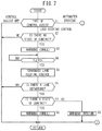
- FIG. 7 is a flowchart of processes performed in the control assisted vehicle according to the present embodiment.
- FIG. 8 is a flowchart of processes performed in the control assisted vehicle according to the present embodiment.
- states in which the driver is touching the steering wheel are distinguished between a “contact state” and a “grasped state”.
- the grasped state or simply grasping refers to a state in which the driver is gripping the steering wheel with palms of his or her hands or a palm of one hand, and the contact area at this time is of a size on the order of the palm.
- the contact state or simply contacting refers to a state in which the driver is touching the steering wheel with one or more fingers or a portion of the palm, and the contact area at this time is of a size that is smaller than the palm.
- the states (contact state, and grasped state) in which the driver (human body) is touching the steering wheel (contact sensor) is referred to as a “hands-on” state
- a state in which the driver (human body) is not touching the steering wheel (contact sensor) is referred to as a “hands-off” state.
- a steering control and an acceleration/deceleration control which are executed by the vehicle, are referred to collectively as a control assist.
- the control assist includes a control assist (automated control) which is executed instead of the manual control performed by the driver, in addition to a control assist (semi-automated control) in which manual controls performed by the driver are partially assisted.
- a control assist automated control
- semi-automated control there are included a lane keeping control, an ACC (autonomous cruise control or adaptive cruise control), and the like.
- the authority for driving the vehicle is on the side of the driver.
- automated operations are included in the automated control.
- the authority for driving the vehicle is on the side of the vehicle.
- temporary override refers to prioritizing the manual control over the automated control, in a state in which the automated control is continued. Further, stopping the automated control, and transferring the authority for driving from the vehicle to the driver is referred to as a “handover”.
- the control assisted vehicle 10 (also referred to simply as a vehicle 10 ) according to the present embodiment includes a control assist device 12 that controls and assists the vehicle 10 , and a contact determining device 16 that determines whether or not a driver H is in contact with and grasping a steering wheel 70 .
- control assist device 12 is equipped with an information detecting unit 20 , a control assist ECU 38 , and controlled devices 52 , 54 , 56 , 58 .
- the information detecting unit 20 is made up from devices (sensors, switches, etc.) for acquiring information necessary for executing the control assist.
- the information detecting unit 20 includes, for example, a camera 22 , a radar 24 , a position measuring device 26 , an automated control starting switch 28 , vehicle velocity sensors 30 , a yaw rate sensor 31 , a torque sensor 32 , an accelerator pedal sensor 34 , and a brake pedal sensor 36 .
- the camera 22 is installed on an upper part on an inner side of the windshield of the vehicle 10 , and captures images of the front of the vehicle 10 .
- a monocular camera or a stereo camera can be used.
- the radar 24 is installed on a front grill of the vehicle 10 , and irradiates electromagnetic waves around the periphery of the vehicle 10 and detects reflected waves.
- a radar device such as a millimeter wave radar, a microwave radar, a laser radar, or the like can be used, or an infrared sensor can also be used.
- a fusion sensor which combines the imaging information from the camera 22 and the detected information from the radar 24 .
- the position measuring device 26 measures the position of the vehicle 10 , and is equipped with a satellite positioning system and a gyroscope or the like for inertial navigation, and a storage unit in which map information is stored including information of segments in which automated driving is possible.
- the automated control starting switch 28 is disposed in the vicinity of the driver's seat, and is operated by the driver H who intends to initiate the control assist.
- the vehicle velocity sensors 30 are provided in each of the vehicle wheels (not shown) of the vehicle 10 , and detect the traveling velocity of the vehicle 10 .
- the yaw rate sensor 31 detects a yaw rate of the vehicle 10 .
- the torque sensor 32 detects a steering torque TR which is generated, for example, in a steering shaft (not shown).
- the accelerator pedal sensor 34 detects an amount at which an accelerator pedal (not shown) is depressed.
- a stroke sensor or a pressure sensor can be used.
- the brake pedal sensor 36 detects an amount at which a brake pedal (not shown) is depressed.
- a stroke sensor or a pressure sensor can be used.
- the control assist ECU 38 is a computational device including a microcomputer, and further includes a CPU, a ROM (including an EEPROM), a RAM, and in addition thereto, input/output devices such as an A/D converter, a D/A converter and the like, and a timer that serves as a timekeeping unit.
- the control assist ECU 38 functions as various function realizing units, such as a control unit, a computation unit, a processing unit, and the like.
- the function realizing units can also be configured in the form of hardware (function implementing devices).
- the control assist ECU 38 may be constituted from only one ECU, or may be constituted from a plurality of ECUs.
- a contact determining ECU 74 to be described later, is configured in the same manner as the control assist ECU 38 .
- control assist ECU 38 functions as an automated driving controller 40 , a driving assist controller 42 , an acceleration/deceleration controller 44 , a steering controller 46 , a switching determination unit 48 , and a warning controller 50 .
- the automated driving controller 40 is configured in a manner so as to perform automated driving, and more specifically, so as to perform a control assist (automated control) instead of a manual control performed by the driver H.
- the automated driving controller 40 is configured to acquire from the information detecting unit 20 information necessary for automated driving, and to formulate action plans for the vehicle 10 .
- the automated driving controller 40 sets a travel route to a destination.
- the automated driving controller 40 sets a travel line, and determines vehicle velocity information, acceleration/deceleration information, and steering information in order to cause the vehicle 10 to travel along the travel line.
- the driving assist controller 42 is configured so as to perform a driving assist, and more specifically, to perform a control assist (semi-automated control) for partially assisting the manual control performed by the driver H.
- a control assist for partially assisting the manual control performed by the driver H.
- the driving assist controller 42 acquires necessary information from the information detecting unit 20 , and determines a steering assist amount so that the vehicle 10 travels substantially at the center of the travel lane.
- the driving assist controller 42 acquires necessary information from the information detecting unit 20 , and determines an acceleration/deceleration control amount in a manner so as to maintain an inter-vehicle distance between the vehicle 10 and a preceding vehicle constant.
- the acceleration/deceleration controller 44 is configured to execute the acceleration/deceleration control on the basis of vehicle velocity information and acceleration/deceleration information, which are determined by the automated driving controller 40 or the driving assist controller 42 .
- the acceleration/deceleration controller 44 outputs acceleration instructions to an acceleration device 52 , and outputs deceleration instructions to a deceleration device 54 .
- the steering controller 46 is configured so as to execute a steering control on the basis of steering information determined by the automated driving controller 40 or the driving assist controller 42 .
- the steering controller 46 outputs steering instructions to a steering device 56 .
- the switching determination unit 48 is configured so as to perform, on the basis of the information acquired from the information detecting unit 20 , a stop determination of the control assist in the semi-automated control, and a stop or a temporary stop determination of the control assist in the automated control. For example, in the case that the driver H operates the steering wheel 70 during a semi-automated control such as a lane keeping control, and the torque sensor 32 has detected a steering torque TR that is greater than or equal to a predetermined value, the switching determination unit 48 instructs the driving assist controller 42 to stop the lane keeping control.
- the driver H desires to carry out an acceleration/deceleration control by way of a manual control.
- the driver H operates the brake pedal (or the accelerator pedal). This is an override operation.
- the brake pedal sensor 36 detects the override operation.
- the switching determination unit 48 instructs the automated driving controller 40 to temporarily stop (override) the acceleration/deceleration control.
- the driver H becomes capable of performing the acceleration/deceleration operation by herself/himself.
- the driver H desires to carry out a steering control by way of a manual control.
- the driver H operates the steering wheel 70 .
- the torque sensor 32 detects the steering torque TR.
- the switching determination unit 48 instructs the automated driving controller 40 to temporarily stop (override) the steering control.
- the driver H becomes capable of performing the steering operation by herself/himself.
- the switching determination unit 48 determines whether or not to transfer the authority for driving from the vehicle 10 to the driver H, or stated otherwise, whether or not a handover is required. For example, when an override operation related to the acceleration/deceleration control and an override operation related to steering are performed within a predetermined time period, the switching determination unit 48 instructs the automated driving controller 40 to stop the automated control (to perform the handover). Further, in the case that the vehicle 10 comes into proximity to an end position of automated driving, the switching determination unit 48 instructs the automated driving controller 40 to stop the automated control (to perform the handover).
- the warning controller 50 is configured so as to output a warning instruction on the basis of the control assist content executed by the automated driving controller 40 and the driving assist controller 42 , and the determination result of the contact determining device 16 . Further, the warning controller 50 is configured to make a request for a handover to the driver H, in response to a request from the switching determination unit 48 .
- the acceleration device 52 operates a drive source of the vehicle 10 in accordance with the acceleration instruction output from the control assist ECU 38 .
- the vehicle 10 is an engine vehicle, a throttle valve or the like is operated in accordance with the acceleration instruction, and thereby operates the drive source (engine).
- the drive source electric motor
- the deceleration device 54 operates a brake actuator in accordance with a deceleration instruction output from the control assist ECU 38 , and thereby operates the brake. At the time of doing so, the vehicle 10 decelerates.
- the steering device 56 operates an electric motor for electric power steering in accordance with a steering instruction output from the control assist ECU 38 .
- the electric motor rotates the steering shaft.
- a warning device 58 operates a speaker and/or a display in response to a warning instruction output from the control assist ECU 38 , and thereby issues a warning. Furthermore, such a warning may be issued by vibrating the steering shaft, a seat belt, the accelerator pedal, or the like.
- the contact determining device 16 comprises the steering wheel 70 and the contact determining ECU 74 .
- the steering wheel 70 constitutes a portion of the steering device 56 that is operated by the driver H when the vehicle 10 is traveling.
- the steering wheel 70 includes a rim portion 70 a formed in an annular shape, a hub portion 70 b connected to the steering shaft, and spoke portions 70 c interposed between the rim portion 70 a and the hub portion 70 b .
- a contact sensor 72 is formed in the rim portion 70 a.
- the rim portion 70 a is a laminated structure the cross section of which is made up from a plurality of layers.
- the rim portion 70 a is equipped with an annular core metal, a resin member, and a leather member, provided in this order toward a radial outer side from a cross-sectional center portion.
- the core metal constitutes a skeletal structure of the rim portion 70 a .
- the resin member is formed in a generally circular cross-sectional shape or an elliptical cross-sectional shape, and covers the entire surface of the metal core with a sufficient thickness, and thereby defines the overall shape of the rim portion 70 a .
- the leather member covers the entire surface of the resin member.
- the contact sensor 72 (the dotted portion shown in FIG. 2 ), which is made up from a conductive material, is formed on the surface of the leather member, and furthermore, a protective film is coated over the entirety of the rim portion 70 a .
- the protective film does not insulate or electrically isolate the surface of the contact sensor 72 .
- the contact sensor 72 is formed, for example, by application of a conductive paint, and covers substantially the entire surface of the leather member.
- the contact sensor 72 is an electrostatic capacitance sensor which, in the case of the hands-on state, utilizes the driver H (human body H) as a capacitor of an electrostatic capacitance Ch.
- the contact sensor 72 may be provided only on a front side (in a rearward direction of the vehicle), may be provided only on a rear side (in a frontward direction of the vehicle), and may be provided only on side surfaces (in a widthwise direction of the vehicle) of the steering wheel 70 . Further, the contact sensor 72 may be divided into a plurality of sensors. In such a case, each of the contact sensors 72 is connected to a later-described contact measurement circuit 76 .
- the contact sensor 72 may be formed around the entire circumference of the steering wheel 70 , or may be formed partially therearound.
- the contact sensor 72 may be a conductive sheet rather than a conductive coating.
- the contact determining ECU 74 is a computation device including a microcomputer.
- the configuration of the ECU is as described previously.
- the contact determining ECU 74 is equipped with the contact measurement circuit 76 , a charge amount measurement unit 78 , and a contact determination unit 80 .
- FIG. 2 shows an equivalent circuit of the contact measurement circuit 76 .
- the contact measurement circuit 76 includes a pulse power source 82 , an amplifier 84 , a first switch 86 , a second switch 88 , and a charging capacitor 90 having a static capacitance Cref.
- a stray capacitance Ce exists inherently in the respective components, the wiring, etc. In this instance, the respective components, the wiring, etc., are regarded as a virtual capacitor 92 of the stray capacitance Ce.
- the electrostatic capacitance Cref of the charging capacitor 90 is set to be sufficiently larger than the stray capacitance Ce and the electrostatic capacitance Ch of the human body H.
- the pulse power source 82 and the amplifier 84 are connected in series.
- the second switch 88 and the charging capacitor 90 are connected in parallel.
- a series circuit made up from the pulse power source 82 and the amplifier 84 is connected to one end, and a parallel circuit made up from the second switch 88 and the charging capacitor 90 is connected to the other end of the first switch 86 .
- an output end of the amplifier 84 , the one end of the first switch 86 , and the contact sensor 72 are electrically connected.
- the pulse power source 82 supplies a constant pulse voltage Vs at a predetermined frequency in accordance with a power supply instruction from the contact determination unit 80 .
- the amplifier 84 amplifies the pulse voltage Vs that is supplied from the pulse power source 82 .
- the first switch 86 is placed in an energized state in accordance with a rise, and is placed in a non-energized state in accordance with a fall in the pulse voltage Vs of the pulse power supply 82 .
- a MOSFET for example, is used as the first switch 86 .
- the second switch 88 is placed in an energized state in accordance with an ON signal, and is placed in a non-energized state in accordance with an OFF signal, which are output from the contact determination unit 80 , as will be described later.
- the charge amount measurement unit 78 is configured in a manner so as to measure the charging voltage Vcref of the charging capacitor 90 .
- the contact determination unit 80 is configured in a manner so as to periodically (for example, every several ten to several hundred milliseconds) output a power supply instruction and a power supply stop instruction to the pulse power source 82 disposed in the contact measurement circuit 76 .
- the contact determination unit 80 is further configured in a manner so as to monitor the number of pulses N (referred to as a pulse number N) generated by the pulse power source 82 , and the charging voltage Vcref of the charging capacitor 90 as measured by the charge amount measurement unit 78 .
- the contact determination unit 80 is configured so as to compare (Nj:Nth) the number of pulses Nj required until the charging voltage Vcref reaches a predetermined charging voltage threshold value Vcth (judgment threshold value) with a pulse threshold value Nth, and to determine whether the hands-on state or the hands-off state is taking place.
- the electrostatic capacitance Ch of the human body H is obtained, and by determining whether it is greater than or equal to an electrostatic capacitance threshold value Cth, the contact state in which the driver H contacts the steering wheel 70 , and the grasped state in which the steering wheel 70 is grasped by the driver H are distinguished.
- the determination result of the contact determination unit 80 is output to the control assist device 12 .
- the contact determining device 16 performs a contact determination on the basis of the charging result of the charging capacitor 90 which is carried out by the contact measurement circuit 76 .
- operations of the contact measurement circuit 76 will be described with reference to FIGS. 3A to 3C and FIGS. 4A and 4B . In this instance, a description will be made assuming the hands-on state, that is, a state in which the driver H (human body H) is touching the contact sensor 72 .
- a power supply instruction is output from the contact determination unit 80 to the pulse power source 82 .
- the supply of power by the pulse power source 82 is initiated in response to the power supply instruction.
- the pulse voltage Vs of the pulse power source 82 rises, as shown in FIG. 3A
- the first switch 86 is placed in a non-conductive state.
- the electric charge moves in the direction indicated by the arrow A.
- the voltage Vhe of the human body H and the virtual capacitor 92 rises, as shown at time t 1 in FIG. 4A . Stated otherwise, the human body H and the virtual capacitor 92 are charged.
- the pulse of the pulse power source 82 falls, as shown in FIG.
- the first switch 86 is placed in a conductive state.
- the electric charge accumulated in the human body H and the virtual capacitor 92 moves in the direction indicated by the arrow B.
- the voltage Vhe of the human body H and the virtual capacitor 92 decreases, as shown at time t 2 in FIG. 4A . Stated otherwise, the human body H and the virtual capacitor 92 are discharged.
- the voltage Vcref of the charging capacitor 90 rises, as shown at time t 2 in FIG. 4B . Stated otherwise, the charging capacitor 90 is charged.
- the electrostatic capacitance Cref of the charging capacitor 90 is sufficiently larger than the stray capacitance Ce and the electrostatic capacitance Ch of the human body H, and therefore, the majority of the charge accumulated in the human body H and the virtual capacitor 92 moves to the charging capacitor 90 .
- the charging voltage Vcref of the charging capacitor 90 reaches the charging voltage threshold value Vcth.
- a power supply stop instruction is output from the contact determination unit 80 to the pulse power source 82 , and supplying of power by the pulse power source 82 is stopped.
- an ON signal is output to the second switch 88 from the contact determination unit 80 .
- the second switch 88 is placed in a conductive state.
- the electric charge accumulated in the charging capacitor 90 moves in the direction indicated by the arrow C. Stated otherwise, the charging capacitor 90 is discharged.
- the number of pulses Nj 2 at the time of the hands-off state (refer to FIGS. 5A and 5B ) becomes longer than the number of pulses Nj 1 at the time of the hands-on state.
- the electrostatic capacitance Ch of the human body H is developed in the following manner. Moreover, in order to facilitate explanation thereof, in the following description, the stray capacitance Ce of the virtual capacitor 92 is not taken into consideration.
- Ch ( Vc th/ Vs ) ⁇ ( C ref/ N ) (5)
- the electrostatic capacitance Ch of the human body H is determined by the charging voltage threshold value Vcth, the voltage Vs of the pulse power source 82 , the static capacitance Cref of the charging capacitor 90 , and the number of pulses N. Moreover, the electrostatic capacitance Ch varies depending on the contact area between the human body H and the contact sensor 72 . Therefore, by measuring the electrostatic capacitance Ch, it is possible to estimate whether the human body H is in contact with the steering wheel 70 (contact sensor 72 ), or is grasping the steering wheel 70 , and further, whether a two-handed grip or a one-handed grip is being made.
- FIG. 6 shows the electrostatic capacitance Ch for cases in which the steering wheel 70 (X1) is grasped with bare hands and with both hands, (X2) is grasped with a bare hand and with one hand, (X3) is contacted with one finger of a bare hand, (Y1) is grasped with both hands while wearing cotton gloves, (Y2) is grasped with one hand while wearing cotton gloves, and (Y3) is contacted with one finger while wearing cotton gloves.
- the steering wheel 70 X1 is grasped with bare hands and with both hands
- (X2) is grasped with a bare hand and with one hand
- X3 is contacted with one finger of a bare hand
- Y1 is grasped with both hands while wearing cotton gloves
- Y2 is grasped with one hand while wearing cotton gloves
- (Y3) is contacted with one finger while wearing cotton gloves.
- the electrostatic capacitance Ch differs in the case that the steering wheel 70 is grasped with both hands (X1, Y1), in the case that the steering wheel 70 is grasped with one hand (X2, Y2), and in the case that the steering wheel 70 is contacted with one finger (X3, Y3).
- the electrostatic capacitance Ch satisfies the relationships X1>X2>X3 and Y1>Y2>Y3.
- an appropriate number of pulses N, and an electrostatic capacitance threshold value Cth at that time is set in advance, and by comparing the electrostatic capacitance Ch of the human body H obtained by the above equation (5) with the electrostatic capacitance threshold value Cth, it is possible to distinguish between a state of grasping and a state of contact.
- a threshold value Cth 1 for distinguishing between the grasped state and the contact state is set within a range including the values X1, X2, Y1, and the grasped state is determined in the case that the electrostatic capacitance Ch of the human body H is greater than or equal to the threshold value Cth 1 , whereas the contact state is determined in the case that the electrostatic capacitance Ch is less than the threshold value Cth 1 . It is also possible to distinguish between the hands-on state and the hands-off state.
- a threshold value Cth 2 for distinguishing between the hands-on state and the hands-off state is set in the vicinity of the value Y3, and the hands-on state can be determined in the case that the electrostatic capacitance Ch of the human body H is greater than or equal to the threshold value Cth 2 , whereas the hands-off state can be determined in the case that the electrostatic capacitance Ch is less than the threshold value Cth 2 .
- grasping and contact states can be distinguished and determined, and hands-on and hands-off states can be distinguished and determined.
- the determination of the hands-on state or the hands-off state can also be obtained by the following method.
- Whether the driver H (human body H) is touching the contact sensor 72 , and more specifically, whether a hands-on or a hands-off state is taking place, is determined by the number of pulses Nj required until the charging voltage Vcref of the charging capacitor 90 reaches the charging voltage threshold value Vcth.
- the hands-off state and the hands-on state differ in terms of the voltage that rises with one supply of power. For this reason, the hands-on case arrives at the charging voltage threshold value Vcth in a shorter time period (the number of pulses N is smaller) than in the hands-off case.
- the present embodiment it is possible to determine that the hands-on state is taking place in the case that the number of pulses Nj required to reach the charging voltage threshold value Vcth is smaller than the pulse threshold value Nth, and to determine that the hands-off state is taking place in the case that the number of pulses Nj is greater than the pulse threshold value Nth.
- the present embodiment it is possible to determine that the hands-on state is taking place in the case that the number of pulses Nj required to reach the charging voltage threshold value Vcth is smaller than the pulse threshold value Nth, and to determine that the hands-off state is taking place in the case that the number of pulses Nj is greater than the pulse threshold value Nth.
- step S 1 in the case that the control assist is not being executed (step S 1 : control assist off), the processes from step S 2 and thereafter are not executed.
- step S 2 In the case that a lane keeping control is being executed (step S 1 : lane keeping control), the process proceeds to step S 2 .
- step S 10 In the case that automated driving is being executed (step S 1 : automated driving), the process proceeds to step S 10 .
- step S 2 on the basis of the determination result of the contact determining device 16 , the driving assist controller 42 determines whether or not a contact state (including the grasped state) is taking place in which the driver H is in contact with the steering wheel 70 . In the case that a period of the contact state (including the grasped state) is not greater than or equal to a predetermined time period, or stated otherwise, in the case that a hands-off state has taken place for greater than or equal to the predetermined time period (step S 2 : YES), the process proceeds to step S 3 .
- step S 2 determines whether the period of the contact state (including the grasped state) is greater than or equal to the predetermined time period (step S 2 : NO). If the period of the contact state (including the grasped state) is greater than or equal to the predetermined time period (step S 2 : NO), the processes from step S 3 and thereafter are not executed. At this time, the driver H is regarded as having an intention to drive.
- step S 3 the driving assist controller 42 makes a request to the warning controller 50 to issue a warning.
- the warning controller 50 outputs a warning instruction to the warning device 58 .
- the warning device 58 issues a warning in accordance with the warning instruction.
- a screen prompting the driver to assume the hands-on state is displayed on the display.
- the electric steering motor is driven in order to vibrate the steering wheel 70 .
- the driving assist controller 42 starts measuring time by the timer T.
- step S 4 the driving assist controller 42 compares the time period measured by the timer T with a time threshold value Tth.
- the time threshold value Tth is a margin time period until the driver H, having been prompted by the warning, contacts (or grasps) the steering wheel 70 .
- the process proceeds to step S 5 .
- the process of step S 4 is repeated.
- step S 5 the driving assist controller 42 terminates the lane keeping control. At the time of doing so, the vehicle 10 is switched over to manual control.
- step S 6 on the basis of imaging information from the camera 22 , the driving assist controller 42 determines the presence or absence of a lane departure. In the case of a lane departure (step S 6 : YES), the process proceeds to step S 7 . On the other hand, if there is not a lane departure (step S 6 : NO), the processes from step S 7 and thereafter are not executed.
- step S 7 on the basis of the determination result of the contact determining device 16 , the driving assist controller 42 again determines whether or not a contact state (including the grasped state) is taking place in which the driver H is in contact with the steering wheel 70 .
- the process proceeds to step S 8 .
- the process proceeds to step S 9 .
- step S 8 and step S 9 the driving assist controller 42 makes a request to the warning controller 50 to issue a warning.
- the warning controller 50 outputs a warning instruction to the warning device 58 .
- the warning device 58 issues a warning in accordance with the warning instruction.
- step S 8 a screen for providing a notification of the lane departure is displayed on the display. Further, the electric steering motor is driven in order to vibrate the steering wheel 70 .
- step S 9 a screen prompting the driver to assume the hands-on state is displayed on the display, and together therewith, a warning sound is emitted. Further, the electric steering motor is driven in order to vibrate the steering wheel 70 .
- step S 10 shown in FIG. 8 the switching determination unit 48 determines whether or not a handover is necessary. In the case that the distance between the travel position of the vehicle 10 as measured by the position measuring device 26 and the ending position of automated driving is less than a predetermined distance, the switching determination unit 48 determines that a handover is necessary (step S 10 : YES). At this time, the switching determination unit 48 instructs the automated driving controller 40 to perform the handover. The process then proceeds to step S 11 . On the other hand, in the case that the distance between the travel position of the vehicle 10 as measured by the position measuring device 26 and the ending position of automated driving is greater than or equal to the predetermined distance, the switching determination unit 48 determines that a handover is not necessary (step S 10 : NO). At this time, the processes of step S 11 and thereafter are not executed.
- step S 11 on the basis of the determination result of the contact determining device 16 , the automated driving controller 40 determines whether or not the grasped state is taking place in which the steering wheel 70 is grasped by the driver H. In the case that the grasped state is not taking place (step S 11 : YES), the process proceeds to step S 12 . On the other hand, in the case that the grasped state is taking place (step S 11 : NO), the process proceeds to step S 14 . At this time, the driver is regarded as having an intention to drive.
- step S 12 the automated driving controller 40 makes a request to the warning controller 50 to issue a warning.
- the warning controller 50 outputs a warning instruction to the warning device 58 .
- the warning device 58 issues a warning in accordance with the warning instruction to prompt the driver to assume a hands-on state. In this instance, a screen prompting the driver to assume the hands-on state is displayed on the display, and together therewith, a warning sound is emitted at a high volume. Further, the electric steering motor is driven in order to vibrate the steering wheel 70 .
- step S 13 the automated driving controller 40 makes a request to the acceleration/deceleration controller 44 to decelerate the vehicle 10 .
- the acceleration/deceleration controller 44 outputs a deceleration instruction to the deceleration device 54 .
- the deceleration device 54 decelerates the vehicle 10 by operating the brake actuator in accordance with the deceleration instruction.
- the processes from step S 11 to step S 13 are repeated until the steering wheel 70 is grasped by the driver H. In the case that the driver H does not grasp the steering wheel 70 , after decelerating, the vehicle 10 is stopped.
- step S 14 the automated driving controller 40 performs a handover, and transfers the authority for driving the vehicle 10 over to the driver H.
- the control assisted vehicle 10 is equipped with the driving assist controller 42 (first controller), the automated driving controller 40 (second controller), the contact determining device 16 (detector), and the warning device (warning unit) 58 .
- the driving assist controller 42 executes the lane keeping control (first automated control) including the steering control assist (first steering control assist) in which the authority for driving is on the side of the driver H.
- the steering control assist that is included in the lane keeping control is a semi-automated control.
- the automated driving controller 40 executes automated driving (second automated control) including the steering control assist (second steering control assist) in which the authority for driving is on the side of the vehicle 10 .
- the steering control assist that is included in automated driving is an automated control.
- the contact determining device 16 distinguishes and detects the contact state in which the driver H contacts the steering wheel 70 , and the grasped state in which the steering wheel 70 is grasped by the driver H (step S 2 and step S 11 ).
- the switching determination unit 48 determines whether or not to transfer the authority for driving from the vehicle 10 to the driver H (step S 10 ).
- the driving assist controller 42 issues a warning by the warning device 58 , in the case that, during execution of the steering control assist, the contact state is not detected by the contact determining device 16 (step S 3 ).
- the automated driving controller 40 issues a warning by the warning device 58 , in the case that, during execution of the steering control assist, it is determined by the switching determination unit 48 that the authority for driving is to be transferred from the vehicle 10 to the driver H, and the grasped state is not detected by the contact determining device 16 (step S 12 ).
- the driving intention of the driver H is confirmed depending on whether or not the contact state exists in which the driver H is in contact with the steering wheel 70 .
- the driving intention of the driver H is confirmed depending on whether or not the grasped state exists in which the steering wheel 70 is grasped by the driver H.
- the contact determining device 16 distinguishes between the contact state and the grasped state by a difference in electrostatic capacitance.
- the contact area between the driver H and the steering wheel 70 becomes smaller in the contact state than in the grasped state. Stated otherwise, the electrostatic capacitance of a capacitor formed by the driver H contacting or grasping the steering wheel 70 becomes smaller in the contact state than in the grasped state. Therefore, by obtaining the electrostatic capacitance, it is possible to accurately distinguish between the contact state and the grasped state.
- the driving assist controller 42 terminates the lane keeping control within a predetermined time period after having issued the warning by the warning device 58 (step S 5 ).
- the automated driving controller 40 issues the warning by the warning device 58 together with executing the deceleration control of the vehicle 10 (step S 13 ).
- the driving assist controller 42 terminating the lane keeping control within the predetermined time period after having issued the warning by the warning unit 58 , the driver H can prepare for suspension of the lane keeping control.
- the automated driving controller 40 transfers the authority for driving from the vehicle 10 to the driver H, the warning is issued by the warning device 58 , together with the deceleration control of the vehicle 10 being executed, and accordingly, high safety can be assured.
- the contact determining device 16 according to the present invention is not limited to the above-described embodiment, and it is a matter of course that various configurations could be adopted therein without departing from the essence and gist of the present invention.
Landscapes
- Engineering & Computer Science (AREA)
- Automation & Control Theory (AREA)
- Transportation (AREA)
- Mechanical Engineering (AREA)
- Human Computer Interaction (AREA)
- Physics & Mathematics (AREA)
- General Physics & Mathematics (AREA)
- Chemical & Material Sciences (AREA)
- Combustion & Propulsion (AREA)
- Steering Controls (AREA)
- Steering Control In Accordance With Driving Conditions (AREA)
- Control Of Driving Devices And Active Controlling Of Vehicle (AREA)
Abstract
Description
ΔQ=Vs×Ch (1)
ΔQ=Cref×ΔVcref (2)
ΔVcref=ΔQ/Cref (2′)
Vcth=ΔVcref×N (3)
Vcth=ΔQ/Cref×N=Vs×Ch/Cref×N (4)
Ch=(Vcth/Vs)×(Cref/N) (5)
- 10: control assisted vehicle (vehicle)
- 16: contact determining device (detector)
- 40: automated driving controller (second controller)
- 42: driving assist controller (first controller)
- 48: switching determination unit (determination unit)
- 58: warning device (warning unit)
- 70: steering wheel
Claims (3)
Applications Claiming Priority (1)
| Application Number | Priority Date | Filing Date | Title |
|---|---|---|---|
| PCT/JP2016/060014 WO2017168540A1 (en) | 2016-03-29 | 2016-03-29 | Control assist vehicle |
Publications (2)
| Publication Number | Publication Date |
|---|---|
| US20200298881A1 US20200298881A1 (en) | 2020-09-24 |
| US10974736B2 true US10974736B2 (en) | 2021-04-13 |
Family
ID=59963702
Family Applications (1)
| Application Number | Title | Priority Date | Filing Date |
|---|---|---|---|
| US16/088,832 Active 2037-05-05 US10974736B2 (en) | 2016-03-29 | 2016-03-29 | Control assist vehicle |
Country Status (4)
| Country | Link |
|---|---|
| US (1) | US10974736B2 (en) |
| JP (1) | JP6661225B2 (en) |
| CN (1) | CN109070924B (en) |
| WO (1) | WO2017168540A1 (en) |
Cited By (2)
| Publication number | Priority date | Publication date | Assignee | Title |
|---|---|---|---|---|
| US11945501B2 (en) | 2019-01-22 | 2024-04-02 | Mercedes-Benz Group AG | Method for operating a lane guidance system and lane guidance system |
| US20250229824A1 (en) * | 2024-01-17 | 2025-07-17 | Honda Motor Co., Ltd. | Steering apparatus |
Families Citing this family (23)
| Publication number | Priority date | Publication date | Assignee | Title |
|---|---|---|---|---|
| KR102019568B1 (en) * | 2017-12-19 | 2019-11-04 | 현대자동차주식회사 | Grip detection system and method of steering wheel for autonomous vehicle |
| WO2019163010A1 (en) * | 2018-02-21 | 2019-08-29 | 本田技研工業株式会社 | Vehicle control system, vehicle control method, and program |
| JP6691568B2 (en) * | 2018-03-29 | 2020-04-28 | 株式会社Subaru | Driving support system |
| JP7066582B2 (en) * | 2018-09-12 | 2022-05-13 | 本田技研工業株式会社 | Judgment system, vehicle control system, vehicle, judgment method, and program |
| CN109849927A (en) * | 2019-01-31 | 2019-06-07 | 爱驰汽车有限公司 | Real-time driving fatigue monitoring system, method, equipment and storage medium |
| CN109819420A (en) * | 2019-02-26 | 2019-05-28 | 奇瑞汽车股份有限公司 | A smart car steering wheel perception upgrade system, control method and smart car |
| US11066025B2 (en) * | 2019-03-27 | 2021-07-20 | Jack Chen | Electric vehicle drive system and operation method of the same |
| CN109903576A (en) * | 2019-04-22 | 2019-06-18 | 爱驰汽车有限公司 | Vehicle lane change based reminding method, system, equipment and storage medium based on navigation |
| CN112217768B (en) * | 2019-07-11 | 2023-04-18 | 华为技术有限公司 | Method and device for transferring driving permission of vehicle |
| JP7067540B2 (en) | 2019-10-23 | 2022-05-16 | トヨタ自動車株式会社 | Vehicle display device |
| US12227190B2 (en) * | 2020-05-26 | 2025-02-18 | The Regents Of The University Of Michigan | Grip-force sensing and shape-changing steering wheel |
| FR3111110B1 (en) * | 2020-06-04 | 2022-07-15 | Autoliv Dev | method for calibrating a vehicle steering wheel measuring device |
| JP7593915B2 (en) * | 2021-12-17 | 2024-12-03 | オートリブ ディベロップメント エービー | Steering wheel device |
| US20250128752A1 (en) * | 2022-01-06 | 2025-04-24 | Autoliv Development Ab | Hands-on detection device and computer program |
| JP7780342B2 (en) * | 2022-01-17 | 2025-12-04 | 本田技研工業株式会社 | Grip detection device |
| JP7477585B1 (en) * | 2022-11-25 | 2024-05-01 | 本田技研工業株式会社 | Steering system |
| JP7605806B2 (en) * | 2022-12-02 | 2024-12-24 | 本田技研工業株式会社 | Steering device and safe driving support system |
| JP7627677B2 (en) | 2022-12-02 | 2025-02-06 | 本田技研工業株式会社 | Steering device |
| JP7605807B2 (en) * | 2022-12-02 | 2024-12-24 | 本田技研工業株式会社 | Steering device |
| CN118683551A (en) | 2023-03-24 | 2024-09-24 | 本田技研工业株式会社 | Driving assistance devices |
| JP2024172873A (en) * | 2023-06-01 | 2024-12-12 | トヨタ自動車株式会社 | Vehicle control device, vehicle control method, and vehicle control computer program |
| JP7734724B2 (en) * | 2023-11-07 | 2025-09-05 | 本田技研工業株式会社 | Steering device |
| JP7748434B2 (en) * | 2023-11-17 | 2025-10-02 | 本田技研工業株式会社 | Steering device |
Citations (11)
| Publication number | Priority date | Publication date | Assignee | Title |
|---|---|---|---|---|
| US3049090A (en) * | 1960-12-19 | 1962-08-14 | William J Bergen | Sleep-preventing alarm for a motor vehicle driver |
| JPH10194150A (en) * | 1997-01-16 | 1998-07-28 | Koyo Seiko Co Ltd | Steering device of automobile |
| JP2007168720A (en) | 2005-12-26 | 2007-07-05 | Honda Motor Co Ltd | Vehicle steering control device and vehicle |
| JP2011070550A (en) * | 2009-09-28 | 2011-04-07 | Toyota Motor Corp | Warning device for vehicle |
| US20120326735A1 (en) | 2011-06-22 | 2012-12-27 | Tk Holdings Inc. | Sensor system for steering wheel for vehicle |
| US20130124046A1 (en) * | 2011-11-11 | 2013-05-16 | Volvo Car Corporation | Arrangement and method for safeguarding driver attentiveness |
| US20160368522A1 (en) * | 2015-06-16 | 2016-12-22 | Steering Solutions Ip Holding Corporation | Retractable steering column assembly and method |
| US20170028995A1 (en) * | 2015-07-31 | 2017-02-02 | Toyota Jidosha Kabushiki Kaisha | Vehicle control apparatus |
| US20170106786A1 (en) * | 2014-03-26 | 2017-04-20 | Nissan Motor Co., Ltd. | Vehicle Information Presenting Device |
| US20170210408A1 (en) * | 2014-07-17 | 2017-07-27 | Panasonic Corporation | Electrostatic steering wheel hold detection device |
| US20170282972A1 (en) * | 2014-10-07 | 2017-10-05 | Jtekt Europe | Securing of a driving assistance function within a power steering |
Family Cites Families (12)
| Publication number | Priority date | Publication date | Assignee | Title |
|---|---|---|---|---|
| JP3094100B1 (en) * | 1999-03-26 | 2000-10-03 | 建設省土木研究所長 | Automatic operation control device |
| JP2002264826A (en) * | 2001-03-09 | 2002-09-18 | Toyota Motor Corp | Automatic driving system for moving objects |
| JP4811025B2 (en) * | 2006-01-06 | 2011-11-09 | トヨタ自動車株式会社 | Vehicle control device |
| JP2007196854A (en) * | 2006-01-26 | 2007-08-09 | Nissan Motor Co Ltd | Driving support device and driving support method |
| JP4797917B2 (en) * | 2006-09-29 | 2011-10-19 | 日本電産株式会社 | Resolver, motor and power steering device |
| DE102006051930B4 (en) * | 2006-11-03 | 2017-04-06 | Robert Bosch Gmbh | Method and device for driver status detection |
| JP5005413B2 (en) * | 2007-04-09 | 2012-08-22 | 株式会社東海理化電機製作所 | In-vehicle device controller |
| CN104487309B (en) * | 2012-07-24 | 2017-03-08 | 丰田自动车株式会社 | Drive assistance device |
| JP6165481B2 (en) * | 2013-03-26 | 2017-07-19 | 住友理工株式会社 | Gripping state detection sensor |
| JP2015131544A (en) * | 2014-01-10 | 2015-07-23 | パナソニックIpマネジメント株式会社 | Vehicle control device |
| JP6201927B2 (en) * | 2014-08-01 | 2017-09-27 | トヨタ自動車株式会社 | Vehicle control device |
| JP6135618B2 (en) * | 2014-08-08 | 2017-05-31 | トヨタ自動車株式会社 | Vehicle control device |
-
2016
- 2016-03-29 WO PCT/JP2016/060014 patent/WO2017168540A1/en not_active Ceased
- 2016-03-29 US US16/088,832 patent/US10974736B2/en active Active
- 2016-03-29 CN CN201680084329.8A patent/CN109070924B/en active Active
- 2016-03-29 JP JP2018507862A patent/JP6661225B2/en active Active
Patent Citations (12)
| Publication number | Priority date | Publication date | Assignee | Title |
|---|---|---|---|---|
| US3049090A (en) * | 1960-12-19 | 1962-08-14 | William J Bergen | Sleep-preventing alarm for a motor vehicle driver |
| JPH10194150A (en) * | 1997-01-16 | 1998-07-28 | Koyo Seiko Co Ltd | Steering device of automobile |
| JP2007168720A (en) | 2005-12-26 | 2007-07-05 | Honda Motor Co Ltd | Vehicle steering control device and vehicle |
| JP2011070550A (en) * | 2009-09-28 | 2011-04-07 | Toyota Motor Corp | Warning device for vehicle |
| US20120326735A1 (en) | 2011-06-22 | 2012-12-27 | Tk Holdings Inc. | Sensor system for steering wheel for vehicle |
| US20130124046A1 (en) * | 2011-11-11 | 2013-05-16 | Volvo Car Corporation | Arrangement and method for safeguarding driver attentiveness |
| US20170106786A1 (en) * | 2014-03-26 | 2017-04-20 | Nissan Motor Co., Ltd. | Vehicle Information Presenting Device |
| US10086753B2 (en) * | 2014-03-26 | 2018-10-02 | Nissan Motor Co., Ltd. | Vehicle information presenting device |
| US20170210408A1 (en) * | 2014-07-17 | 2017-07-27 | Panasonic Corporation | Electrostatic steering wheel hold detection device |
| US20170282972A1 (en) * | 2014-10-07 | 2017-10-05 | Jtekt Europe | Securing of a driving assistance function within a power steering |
| US20160368522A1 (en) * | 2015-06-16 | 2016-12-22 | Steering Solutions Ip Holding Corporation | Retractable steering column assembly and method |
| US20170028995A1 (en) * | 2015-07-31 | 2017-02-02 | Toyota Jidosha Kabushiki Kaisha | Vehicle control apparatus |
Non-Patent Citations (1)
| Title |
|---|
| International Search Report and Written Opinion for International Application No. PCT/JP2016/060014 dated Jun. 14, 2016, 7 pages. |
Cited By (2)
| Publication number | Priority date | Publication date | Assignee | Title |
|---|---|---|---|---|
| US11945501B2 (en) | 2019-01-22 | 2024-04-02 | Mercedes-Benz Group AG | Method for operating a lane guidance system and lane guidance system |
| US20250229824A1 (en) * | 2024-01-17 | 2025-07-17 | Honda Motor Co., Ltd. | Steering apparatus |
Also Published As
| Publication number | Publication date |
|---|---|
| WO2017168540A1 (en) | 2017-10-05 |
| CN109070924A (en) | 2018-12-21 |
| JPWO2017168540A1 (en) | 2018-11-08 |
| JP6661225B2 (en) | 2020-03-11 |
| US20200298881A1 (en) | 2020-09-24 |
| CN109070924B (en) | 2021-03-26 |
Similar Documents
| Publication | Publication Date | Title |
|---|---|---|
| US10974736B2 (en) | Control assist vehicle | |
| US11027748B2 (en) | Automatic driving control device | |
| CN108995715B (en) | steering assist | |
| CN109476319B (en) | Driving assistance device | |
| US11001271B2 (en) | Drive assistance device | |
| US11104367B2 (en) | Steering wheel unit | |
| EP2782082B1 (en) | Drive assisting apparatus | |
| US10202121B2 (en) | Stop control device | |
| US10053097B2 (en) | Vehicle control apparatus and vehicle control method | |
| CN107531243A (en) | Automatic Pilot control device | |
| JP6406761B2 (en) | Holding state detection device | |
| US20160257222A1 (en) | Vehicle parking control device | |
| CN106114517A (en) | Allow to carry out the Vehicular system changed, the vehicle including this Vehicular system and the method allowing this conversion from autonomous driving pattern | |
| US10983517B2 (en) | Vehicle control device | |
| CN117651671B (en) | Driving mode switching control method and driving mode switching control device for vehicle | |
| CN113428147A (en) | Vehicle control device and vehicle control method | |
| CN111391835A (en) | vehicle control device | |
| CN111391827B (en) | vehicle control device | |
| JP2017182270A (en) | Driving state determination device | |
| JP2016021192A (en) | State determination device | |
| KR102281652B1 (en) | Autonomous Emergency Braking System and Longitudinal Acceleration Intention Estimation Therefor | |
| CN113525371A (en) | Vehicle control device and vehicle control method | |
| JP2014203261A (en) | Vehicle operation state estimation device | |
| JP2023035542A (en) | Lane deviation prevention device | |
| JP2023035541A (en) | Lane deviation prevention device |
Legal Events
| Date | Code | Title | Description |
|---|---|---|---|
| AS | Assignment |
Owner name: HONDA MOTOR CO., LTD., JAPAN Free format text: ASSIGNMENT OF ASSIGNORS INTEREST;ASSIGNORS:ODATE, SHOTARO;SAKAMOTO, NAOHIRO;OSHIDA, KEI;REEL/FRAME:046985/0888 Effective date: 20180827 |
|
| FEPP | Fee payment procedure |
Free format text: ENTITY STATUS SET TO UNDISCOUNTED (ORIGINAL EVENT CODE: BIG.); ENTITY STATUS OF PATENT OWNER: LARGE ENTITY |
|
| STPP | Information on status: patent application and granting procedure in general |
Free format text: NOTICE OF ALLOWANCE MAILED -- APPLICATION RECEIVED IN OFFICE OF PUBLICATIONS |
|
| STPP | Information on status: patent application and granting procedure in general |
Free format text: PUBLICATIONS -- ISSUE FEE PAYMENT VERIFIED |
|
| STCF | Information on status: patent grant |
Free format text: PATENTED CASE |
|
| MAFP | Maintenance fee payment |
Free format text: PAYMENT OF MAINTENANCE FEE, 4TH YEAR, LARGE ENTITY (ORIGINAL EVENT CODE: M1551); ENTITY STATUS OF PATENT OWNER: LARGE ENTITY Year of fee payment: 4 |