US10937192B2 - Resolving incorrect distributed simultaneous localization and mapping (SLAM) data in edge cloud architectures - Google Patents
Resolving incorrect distributed simultaneous localization and mapping (SLAM) data in edge cloud architectures Download PDFInfo
- Publication number
- US10937192B2 US10937192B2 US16/425,656 US201916425656A US10937192B2 US 10937192 B2 US10937192 B2 US 10937192B2 US 201916425656 A US201916425656 A US 201916425656A US 10937192 B2 US10937192 B2 US 10937192B2
- Authority
- US
- United States
- Prior art keywords
- hmd
- ihs
- golden
- response
- references
- Prior art date
- Legal status (The legal status is an assumption and is not a legal conclusion. Google has not performed a legal analysis and makes no representation as to the accuracy of the status listed.)
- Active, expires
Links
Images


Classifications
-
- G—PHYSICS
- G06—COMPUTING OR CALCULATING; COUNTING
- G06F—ELECTRIC DIGITAL DATA PROCESSING
- G06F3/00—Input arrangements for transferring data to be processed into a form capable of being handled by the computer; Output arrangements for transferring data from processing unit to output unit, e.g. interface arrangements
- G06F3/01—Input arrangements or combined input and output arrangements for interaction between user and computer
- G06F3/011—Arrangements for interaction with the human body, e.g. for user immersion in virtual reality
- G06F3/013—Eye tracking input arrangements
-
- G—PHYSICS
- G06—COMPUTING OR CALCULATING; COUNTING
- G06T—IMAGE DATA PROCESSING OR GENERATION, IN GENERAL
- G06T7/00—Image analysis
- G06T7/70—Determining position or orientation of objects or cameras
- G06T7/73—Determining position or orientation of objects or cameras using feature-based methods
- G06T7/74—Determining position or orientation of objects or cameras using feature-based methods involving reference images or patches
-
- G—PHYSICS
- G01—MEASURING; TESTING
- G01C—MEASURING DISTANCES, LEVELS OR BEARINGS; SURVEYING; NAVIGATION; GYROSCOPIC INSTRUMENTS; PHOTOGRAMMETRY OR VIDEOGRAMMETRY
- G01C21/00—Navigation; Navigational instruments not provided for in groups G01C1/00 - G01C19/00
- G01C21/26—Navigation; Navigational instruments not provided for in groups G01C1/00 - G01C19/00 specially adapted for navigation in a road network
- G01C21/28—Navigation; Navigational instruments not provided for in groups G01C1/00 - G01C19/00 specially adapted for navigation in a road network with correlation of data from several navigational instruments
- G01C21/30—Map- or contour-matching
- G01C21/32—Structuring or formatting of map data
-
- G—PHYSICS
- G01—MEASURING; TESTING
- G01C—MEASURING DISTANCES, LEVELS OR BEARINGS; SURVEYING; NAVIGATION; GYROSCOPIC INSTRUMENTS; PHOTOGRAMMETRY OR VIDEOGRAMMETRY
- G01C21/00—Navigation; Navigational instruments not provided for in groups G01C1/00 - G01C19/00
- G01C21/38—Electronic maps specially adapted for navigation; Updating thereof
- G01C21/3804—Creation or updating of map data
- G01C21/3807—Creation or updating of map data characterised by the type of data
- G01C21/3811—Point data, e.g. Point of Interest [POI]
-
- G—PHYSICS
- G02—OPTICS
- G02B—OPTICAL ELEMENTS, SYSTEMS OR APPARATUS
- G02B27/00—Optical systems or apparatus not provided for by any of the groups G02B1/00 - G02B26/00, G02B30/00
- G02B27/01—Head-up displays
- G02B27/017—Head mounted
-
- G—PHYSICS
- G06—COMPUTING OR CALCULATING; COUNTING
- G06F—ELECTRIC DIGITAL DATA PROCESSING
- G06F3/00—Input arrangements for transferring data to be processed into a form capable of being handled by the computer; Output arrangements for transferring data from processing unit to output unit, e.g. interface arrangements
- G06F3/01—Input arrangements or combined input and output arrangements for interaction between user and computer
- G06F3/011—Arrangements for interaction with the human body, e.g. for user immersion in virtual reality
-
- G—PHYSICS
- G06—COMPUTING OR CALCULATING; COUNTING
- G06T—IMAGE DATA PROCESSING OR GENERATION, IN GENERAL
- G06T17/00—Three dimensional [3D] modelling, e.g. data description of 3D objects
- G06T17/05—Geographic models
-
- G—PHYSICS
- G06—COMPUTING OR CALCULATING; COUNTING
- G06T—IMAGE DATA PROCESSING OR GENERATION, IN GENERAL
- G06T7/00—Image analysis
- G06T7/30—Determination of transform parameters for the alignment of images, i.e. image registration
- G06T7/33—Determination of transform parameters for the alignment of images, i.e. image registration using feature-based methods
- G06T7/337—Determination of transform parameters for the alignment of images, i.e. image registration using feature-based methods involving reference images or patches
-
- G—PHYSICS
- G06—COMPUTING OR CALCULATING; COUNTING
- G06T—IMAGE DATA PROCESSING OR GENERATION, IN GENERAL
- G06T2207/00—Indexing scheme for image analysis or image enhancement
- G06T2207/30—Subject of image; Context of image processing
- G06T2207/30244—Camera pose
Definitions
- the present disclosure generally relates to Information Handling Systems (IHSs), and, more particularly, to systems and methods for resolving incorrect distributed Simultaneous Localization and Mapping (SLAM) data in edge cloud architectures.
- IHSs Information Handling Systems
- SLAM Simultaneous Localization and Mapping
- IHSs Information Handling Systems
- An IHS generally processes, compiles, stores, and/or communicates information or data for business, personal, or other purposes thereby allowing users to take advantage of the value of the information.
- IHSs may also vary regarding what information is handled, how the information is handled, how much information is processed, stored, or communicated, and how quickly and efficiently the information may be processed, stored, or communicated.
- the variations in IHSs allow for IHSs to be general or configured for a specific user or specific use such as financial transaction processing, airline reservations, enterprise data storage, or global communications.
- IHSs may include a variety of hardware and software components that may be configured to process, store, and communicate information and may include one or more computer systems, data storage systems, and networking systems.
- IHSs may be used to produce virtual, augmented, or mixed reality (xR) applications.
- VR virtual reality
- a conventional VR device obscures a user's real-world surroundings, such that only digitally-generated images remain visible.
- AR augmented reality
- MR mixed reality
- a typical AR/MR device includes a projection-based optical system that displays content on a translucent or transparent surface of an HMD, heads-up display (HUD), eyeglasses, or the like (collectively “HMDs”).
- HMDs may be tethered to an external or host IHS. Most HMDs do not have as much processing capability as the host IHS, so the host IHS is used to generate the digital images to be displayed by the HMD.
- the HMD transmits information to the host IHS regarding the state of the user, which in turn enables the host IHS to determine which image or frame to show to the user next, and from which perspective, as the user moves in space.
- an Information Handling System may include: a processor; and a memory coupled to the processor, the memory having program instructions stored thereon that, upon execution, cause the IHS to: receive SLAM data obtained by a first Head-Mounted Device (HMD), where the SLAM data comprises a first plurality of landmarks usable to produce a first map of a physical space for the first HMD; select a first set of golden references among the first plurality of landmarks; receive, from a second IHS coupled to a second HMD, a second set of golden references selected among a second plurality of landmarks usable to produce a second map of the physical space for the second HMD; determine that a first instance of a given golden reference in the first set of golden references matches a second instance of the given golden reference in the second set of golden references
- the SLAM data may include landmark data found in a Region of Interest (ROI) within an infrared (IR) or near-IR (NIR) frame captured via a camera mounted on the first HMD.
- ROI Region of Interest
- NIR near-IR
- the program instructions upon execution, may cause the IHS to identify one or more IR markers captured in an ROI overlap between the first and second HMDs. Additionally, or alternatively, the IHS may perform an object recognition operation in an ROI overlap between the first and second HMDs.
- the second IHS may be: a co-located server in response to the first HMD having a first latency requirement, an edge server in response to the first HMD having a second latency requirement smaller than the first latency requirement, or a cloud server in response to the first HMD having a third latency requirement smaller than the second latency requirement. Additionally, or alternatively, the second IHS may be: a co-located server in response to the first HMD having a first compute requirement, an edge server in response to the first HMD having a second compute requirement greater than the first compute requirement, or a cloud server in response to the first HMD having a third compute requirement greater than the second compute requirement.
- the second IHS may be: a co-located server in response to the first HMD moving with a first speed, an edge server in response to the first HMD moving with a second speed smaller than the first speed, or a cloud server in response to the first HMD moving with a third speed smaller than the second speed.
- the second IHS may be: a co-located server in response to the first instance of the given golden reference having moved with a first speed in previous SLAM data, an edge server in response to the first instance of the given golden reference having moved with a second speed smaller than the first speed in previous SLAM data, or a cloud server in response to the first instance of the given golden reference having moved with a third speed smaller than the second speed in the previous SLAM data.
- the program instructions upon execution, may cause the IHS to: receive, from a third IHS coupled to a third HMD, a third set of golden references selected among a third plurality of landmarks usable to produce a third map of the physical space for the third HMD; identify a third instance of the given golden reference in the third set of golden references; and increase the count of incorrect golden references, in part, in response to the first and third instances of the given golden reference being separated from each other by the threshold distance.
- the program instructions upon execution, may further cause the IHS to determine, based upon the second and third sets of golden references, a current position of the first HMD. Moreover, the program instructions, upon execution, may cause the IHS to: determine, a difference between: (i) the current position of the first HMD; and (ii) a position of the first HMD as detected by the first HMD; and compensate the location of newly selected golden landmarks used to produce the new first map of the physical space based on the difference.
- a method may include receiving SLAM data obtained by a first HMD, where the SLAM data comprises a first plurality of landmarks usable to produce a first map of a physical space for the first HMD; selecting a first set of golden references among the first plurality of landmarks; receiving, from a second IHS coupled to a second HMD, a second set of golden references selected among a second plurality of landmarks usable to produce a second map of the physical space for the second HMD; determining that a first instance of a given golden reference in the first set of golden references matches a second instance of the given golden reference in the second set of golden references; in response to the first and second instances of the given golden reference being separated from each other by a threshold distance, increasing a count of incorrect golden references; in response to the count of incorrect golden references being greater than a threshold value, producing a new first map of the physical space for the first HMD; identifying a difference between: (i) a current position of the first
- the second IHS may be: a co-located server in response to the first HMD having a first latency requirement, an edge server in response to the first HMD having a second latency requirement, or a cloud server in response to the first HMD having a third latency requirement. Additionally, or alternatively, the second IHS may be: a co-located server in response to the first HMD having a first compute requirement, an edge server in response to the first HMD having a second compute requirement, or a cloud server in response to the first HMD having a third compute requirement.
- the second IHS may be: a co-located server in response to the first HMD moving with a first speed, an edge server in response to the first HMD moving with a second speed, or a cloud server in response to the first HMD moving with a third speed. Additionally, or alternatively, the second IHS may be: a co-located server in response to the first instance of the given golden reference having moved with a first speed in previous SLAM data, an edge server in response to the first instance of the given golden reference having moved with a second speed in previous SLAM data, or a cloud server in response to the first instance of the given golden reference having moved with a third speed in previous SLAM data.
- FIGS. 1A-D illustrate an example of an environment where a virtual, augmented, or mixed reality (xR) application may be executed, according to some embodiments.
- xR mixed reality
- FIG. 2 illustrates an example of electronic components of a Head-Mounted Display (HMD), according to some embodiments.
- HMD Head-Mounted Display
- FIG. 3 illustrates an example of electronic components of an Information Handling System (IHS), according to some embodiments.
- IHS Information Handling System
- FIG. 4 illustrates an example of logic components of an xR application, according to some embodiments.
- FIGS. 5A and 5B illustrate an example of a method for resolving incorrect distributed Simultaneous Localization and Mapping (SLAM) data in edge cloud architectures, according to some embodiments.
- SLAM Simultaneous Localization and Mapping
- Embodiments described herein provide systems and methods for resolving incorrect distributed Simultaneous Localization and Mapping (SLAM) data in edge cloud architectures. These techniques are particularly useful in virtual, augmented, and mixed reality (xR) applications that employ Head-Mounted Devices (HMDs), Heads-Up Displays (HUDs), and eyeglasses—collectively referred to as “HMDs.”
- HMDs Head-Mounted Devices
- HUDs Heads-Up Displays
- eyeglasses eyeglasses
- SLAM distributed SLAM
- client nodes perform SLAM collaboratively to create a map (a “SLAM map”) of their shared physical space.
- SLAM map a map of their shared physical space.
- distributed SLAM cannot always maintain full synchronization among client nodes, which often produces some amount of drift in the accuracy (e.g., position, size, staleness, etc.) of the SLAM maps constructed using such methods.
- systems and methods described herein may periodically detect and resolve incorrect landmarks found in a shared or distributed SLAM map.
- a client node e.g., an HMD coupled to a supporting IHS
- Multiple HMDs may be co-located in a given space, and their supporting IHSs may be either co-located or part of an edge cloud architecture.
- a client node may periodically transmit its relative pose, as well as the coordinates of its golden references, as a beacon, to other nodes.
- the client node may apply one or more rules, for each ROI of its SLAM map, to verify whether its golden references(s) for that ROI are within selected tolerance values. If not, the client node may replace the corrupted golden references with another node's golden references(s). Additionally, or alternatively, the client node may refresh its SLAM map with an asynchronous request to other relevant client nodes for their partial SLAM maps.
- systems and methods described herein may use self-correction mechanisms from distributed compute architectures to resolve critical SLAM landmarks data periodically as a way to compensate for built in probabilistic estimation inaccuracies in Extended Kalman Filtering (EKF) SLAM.
- EKF Extended Kalman Filtering
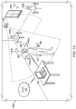
- FIG. 1A is a perspective view of environment 100 A where an xR application is executed.
- user 101 wears HMD 102 around his or her head and over his or her eyes.
- HMD 102 is tethered to host Information Handling System (IHS) 103 via a wired or wireless connection.
- IHS Information Handling System
- host IHS 103 may be built into (or otherwise coupled to) a backpack or vest, wearable by user 101 .
- two or more users may be in the same environment or room 100 A such that their respective HMDs may be said to be co-located.
- co-located HMDs may be within a predefined physical distance from each other (e.g., up to 10 meters), and each HMD worn by each user may be coupled to a distinct IHS.
- the IHS serving a particular HMD may be part of an edge cloud architecture.
- the xR application may include a subset of components or objects operated by HMD 102 and another subset of components or objects operated by host IHS 103 .
- host IHS 103 may be used to generate digital images to be displayed by HMD 102 .
- HMD 102 transmits information to host IHS 103 regarding the state of user 101 , such as physical position, pose or head orientation, gaze focus, etc., which in turn enables host IHS 103 to determine which image or frame to display to the user next, and from which perspective.
- Movement of the user's head and gaze may be detected by HMD 102 and processed by host IHS 103 , for example, to render video frames that maintain visual congruence with the outside world and/or to allow user 101 to look around a consistent virtual reality environment.
- xR application components executed by HMD 102 and IHS 103 may provide a cooperative, at least partially shared, xR environment among a plurality of users. For example, each user may wear their own HMD tethered to a different host IHS, such as in the form of a video game or a productivity application (e.g., a virtual meeting).
- FIG. 1B shows a co-located multi-user xR implementation with three participants 101 A-C, each participant wearing their own HMD 102 A-C.
- each of HMDs 102 A-C may be tethered to its own dedicated IHS 103 A-C.
- a first number M of HMDs and a second number N of IHSs may be used (e.g., one IHS “server” for two HMD “clients,” etc.).
- each of the IHSs may have different compute capabilities; and that all HMDs are using inside-out Extended Kalman Filtering (EKF) SLAM tracking, with wide mapping field of view up to 360 degrees (e.g., with surround sensors and/or cameras).
- EKF Extended Kalman Filtering
- each HMD 102 A-C may include an instance of inside-out camera 108 configured to capture IR/NIR frames, and therefore sends those frames and associated data (SLAM data) to its respective IHS 103 A-C. Then, each IHS 103 A-C determines one or more Regions-of-Interest (ROIs) 111 A-C within the HMD 102 A-C's respectively captured frames and/or field-of-view (FOV), and performs one or more SLAM operations upon the SLAM data obtained for each ROI.
- ROI may be equal to an FOV plus a delta 3D range for anticipatory movements.
- ROI intersection area 112 may occur, for example, such that redundant or duplicate calculations are performed by HMDs 102 A-C for landmarks found in that intersection.
- FIG. 1C shows HMD client nodes 102 A-M connected wired/wirelessly in a mesh ad-hoc network architecture to IHS server nodes 103 A-N.
- one of IHS nodes 103 A-N e.g., the first node to start the xR collaboration session
- remote edge server 103 C and/or remote cloud server 103 N may enable co-located IHSs 103 A and 103 B (with respect to HMDs 102 A-M) to offload xR processing and/or additional operations to it, as part of an edge cloud architecture, or the like.
- FIG. 1D shows an example of an edge cloud compute architecture usable by any of HMD client nodes 102 A-M to access a respective one of IHS nodes 103 A-N, according to some embodiments.
- edge server 113 may be in close proximity to the last mile of a wireless network serving HMD 102 and/or IHS 103 ; that is, at the edge of that network.
- cloud server 114 may include any virtualized or physical IHS that provides computation and data storage services remotely through the Internet, or the like. Different levels of round-trip latency are involved in communications between a given HMD and respective ones of co-located IHS 103 , edge server 113 , and cloud server 114 , increasing from left to right.
- HMD 102 may be an all-in-one (AIO) device with enough compute power to operate untethered from any IHS, such that all processing is entirely performed by HMD 102 , which results in Very Low Latency (VLL) processing. Additionally, or alternatively, HMD 102 may be tethered to a co-located IHS 103 , mobile (e.g., backpack or vest) or fixed (e.g., on a desk), such that the external IHS 103 's compute resources are used, resulting in Low Latency (LL) processing/communications.
- AIO all-in-one
- VLL Very Low Latency
- HMD 102 may be configured to use compute resources available at edge server 113 (directly or via indirectly via IHS 103 ), resulting in Mid Latency (ML) processing/communications. Additionally, or alternatively, HMD 102 may be configured to use compute resources available at cloud server 114 (directly or via indirectly via IHSs 103 and/or 113 ), resulting in High Latency (HL) processing/communications.
- edge server 113 directly or via indirectly via IHS 103
- ML Mid Latency
- HMD 102 may be configured to use compute resources available at cloud server 114 (directly or via indirectly via IHSs 103 and/or 113 ), resulting in High Latency (HL) processing/communications.
- HL High Latency
- VLL may have a round-trip latency smaller than 20 ms
- LL may have a round-trip latency between 20 ms and 50 ms
- ML may have a round-trip latency between 50 ms and 200 ms
- HL may have a round-trip latency greater than 200 ms.
- the example edge cloud architecture of FIG. 1D also has different levels of computation resources available, increasing in capabilities from left ( 102 ) to right ( 114 ). Particularly, HMD 102 is deemed to have Very Low Computation (VLC) capability, co-located IHS 103 has Low Computation (LC) capabilities, edge server 113 has Medium Computation (MC) capabilities, and cloud server 114 has High Computation (HC) capabilities.
- VLC Very Low Computation
- LC Low Computation
- MC Medium Computation
- HC High Computation
- HC may include a deep learning and object recognition pipeline
- MC may include dense SLAM compute and/or VR ready-line graphics (e.g., in Kflops/pixel)
- LC may include Dynamic Time Warping (DTW)
- VLC may implement constrained channel bitrate adaptation mechanisms.
- each of computation capacities VLC-HC may be quantified on a scale (e.g., numerically) with respect to an amount of processing power, access to data, and/or ability to perform complex algorithms such as machine learning, object recognition, tagging, etc.
- each IHS node in an edge cloud compute architecture may be further characterized by its ability to process video frames captured by HMD 102 , for example, to perform SLAM computations.
- IHS 103 may be capable of performing SLAM computations at 30 frames-per-second (FPS)
- edge server 113 may perform SLAM computations at 10 FPS
- cloud server 114 may perform SLAM computations at 1 FPS.
- SLAM operations e.g., compute, accuracy
- HMDs various HMDs and their respective IHSs
- speed up mapping e.g., localization and tracking map updates
- FIG. 2 illustrates an example of electronic components of HMD 102 .
- HMD 102 comprises a projection system that includes projector 204 configured to display image frames, including stereoscopic right and left images, on right and left displays 203 R and 203 L that are viewed by a user right and left eyes 101 R and 101 L, respectively.
- a projection system may include, for example, a Digital Light Processing (DLP), a Liquid Crystal Display (LCD), or the like.
- DLP Digital Light Processing
- LCD Liquid Crystal Display
- VOs virtual objects
- HMD 102 includes processor 205 configured to generate frames that are displayed by projector 204 .
- Hardware memory 207 is configured to store program instructions executable by processor 205 , as well as other data. In other embodiments, however one or more operations described for processor 205 may be implemented by a different processor within IHS 103 .
- HMD 102 may also include control interface 208 and video interface 209 (e.g., a Bluetooth technology interface, USB interface, etc.)
- control interface 208 and video interface 209 e.g., a Bluetooth technology interface, USB interface, etc.
- Control interface 208 may provide forward and backward communication channels between HMD 102 and IHS 103 , depending upon the architecture of the xR system, to facilitate execution of an xR application.
- program instructions stored in memory 207 when executed by processor 205 , may cause frames captured by camera(s) 108 to be transmitted to IHS 103 via control interface 208 .
- IHS 103 may in turn execute SLAM module 403 ( FIG. 4 ), for example, based upon landmarks found in the video frames received from camera 108 .
- SLAM module 403 may be configured to implement tracking techniques that use distinctive visual characteristics of the physical environment to identify specific images or shapes which are then usable to calculate HMD 102 's position and orientation.
- rendering engine 406 FIG. 4
- video interface 209 may include two separate video interfaces, one for each display 203 R/L. Additionally, or alternatively, a single interface that supports multi-stream may be used to drive both displays 203 R/L.
- HMD 102 may include one or more sensors 206 that collect information about the user's environment (e.g., video, depth, lighting, motion, etc.) and provide that information to processor 205 .
- Sensors 206 may include, but are not limited to, inside-out cameras, outside-in cameras, eye tracking cameras, RGB cameras, gesture cameras, infrared (IR) or near-IR (NIR) cameras, SLAM cameras, etc. Additionally, or alternatively, sensors 206 may include electric, magnetic, radio, optical, infrared, thermal, force, pressure, acoustic, ultrasonic, proximity, position, deformation, movement, velocity, rotation, gyroscopic, and/or acceleration sensor(s). In some cases, sensors 206 may be coupled to processor 205 via a sensor hub.
- HMD 102 may be configured to render and display frames to provide an xR view for user 101 according to inputs from sensors 206 .
- an xR view may include renderings of the user's real-world environment based on video captured by camera 108 .
- the xR view may also include virtual objects composited with the projected view of the user's real environment.
- NIR light sources 201 R and 201 L may be positioned in HMD 102 to illuminate the user's eyes 101 R and 101 L, respectively.
- Mirrors 201 R and 201 L e.g., “hot mirrors” may be positioned to direct NIR light reflected from eyes 101 R and 101 L into EGT cameras 202 R and 202 L located on each side of the user's face.
- EGT cameras 202 R and 202 L instead of EGT cameras 202 R and 202 L, a single EGT camera, or a combination of a wide-angle camera with and a narrower-angle camera, may be used.
- EGT information captured by cameras 202 R and 202 L may be provided to processor 205 to be further processed and/or analyzed.
- processor 205 may adjust the rendering of images to be projected, and/or it may adjust the projection of the images by the projector 204 based on the direction and angle at which eyes 101 R/L are looking. Additionally, or alternatively, processor 205 may estimate the point of gaze on right and left displays 203 R and 203 L to enable gaze-based interaction with xR content shown on those displays.
- an IHS may include any instrumentality or aggregate of instrumentalities operable to compute, calculate, determine, classify, process, transmit, receive, retrieve, originate, switch, store, display, communicate, manifest, detect, record, reproduce, handle, or utilize any form of information, intelligence, or data for business, scientific, control, or other purposes.
- an IHS may be a personal computer (e.g., desktop or laptop), tablet computer, mobile device (e.g., Personal Digital Assistant (PDA) or smart phone), server (e.g., blade server or rack server), a network storage device, or any other suitable device and may vary in size, shape, performance, functionality, and price.
- An IHS may include Random Access Memory (RAM), one or more processing resources such as a Central Processing Unit (CPU) or hardware or software control logic, Read-Only Memory (ROM), and/or other types of nonvolatile memory.
- RAM Random Access Memory
- CPU Central Processing Unit
- ROM Read-Only Memory
- Additional components of an IHS may include one or more disk drives, one or more network ports for communicating with external devices as well as various I/O devices, such as a keyboard, a mouse, touchscreen, and/or a video display.
- An IHS may also include one or more buses operable to transmit communications between the various hardware components. An example of an IHS is described in more detail below.
- FIG. 3 is a block diagram of IHS 300 configured to implement host IHS 103 , according to certain embodiments.
- IHS 300 may include one or more processors 301 .
- IHS 300 may be a single-processor system including one processor 301 , or a multi-processor system including two or more processors 301 .
- Processor(s) 301 may include any processor capable of executing program instructions, such as an Intel PentiumTM series processor or any general-purpose or embedded processors having any of a variety of Instruction Set Architectures (ISAs), such as the x86, POWERPC®, ARM®, SPARC®, or MIPS® ISAs, or any other suitable ISA.
- ISAs Instruction Set Architectures
- IHS 300 includes chipset 302 that may include one or more integrated circuits that are connect to processor(s) 301 .
- chipset 302 may utilize QuickPath Interconnect (QPI) bus 303 for communicating with the processor(s) 301 .
- Chipset 302 provides the processor(s) 301 with access to a variety of resources. For instance, chipset 302 provides access to system memory 305 over memory bus 304 .
- System memory 305 may be configured to store program instructions and/or data accessible by processors(s) 301 .
- system memory 305 may be implemented using any suitable memory technology, such as static RAM (SRAM), dynamic RAM (DRAM) or nonvolatile/Flash-type memory.
- Chipset 302 may also provide access to graphics processor 307 .
- graphics processor 307 may be comprised within one or more video or graphics cards that have been installed as components of IHS 300 .
- Graphics processor 307 may be coupled to the chipset 302 via a graphics bus 306 such as provided by an Accelerated Graphics Port (AGP) bus or a Peripheral Component Interconnect Express (PCIe) bus.
- graphics processor 307 generates display signals and provides them to HMD device 102 via video interface 204 .
- chipset 302 may also provide access to one or more user input devices 311 .
- chipset 302 may be coupled to a super I/O controller 310 that provides interfaces for a variety of user input devices 311 , in particular lower bandwidth and low data rate devices.
- super I/O controller 310 may provide access to a keyboard and mouse or other peripheral input devices.
- super I/O controller 310 may be used to interface with coupled user input devices 311 such as keypads, biometric scanning devices, and voice or optical recognition devices, through wired or wireless connections.
- chipset 302 may be coupled to the super I/O controller 310 via a Low Pin-Count (LPC) bus 313 .
- LPC Low Pin-Count
- chipset 302 may be coupled to a network interface 309 , such as provided by a Network Interface Controller (NIC) that is coupled to IHS 300 .
- NIC Network Interface Controller
- the network interface 309 may be coupled to the chipset 302 via a PCIe bus 312 .
- network interface 309 may support communication via various wired and/or wireless networks.
- the chipset 302 may also provide access to one or more Universal Serial Bus (USB) ports 316 ; which in some implementations may serve as transport for establishing control interface 203 with HMD 102 .
- USB Universal Serial Bus
- Chipset 302 also provides access to one or more solid-state storage devices 315 .
- the chipset 302 utilizes a PCIe bus interface connection 318 in order to communicate with the solid-state storage device 315 .
- chipset 302 may also provide access to other types of storage devices.
- an IHS 300 may also utilize one or more magnetic disk storage devices, or other types of the storage devices such as an optical drive or a removable-media drive.
- the solid-state storage device 315 may be integral to IHS 300 , or may be located remotely from IHS 300 .
- BIOS 317 Another resource that may be accessed by processor(s) 301 via chipset 302 is a Basic Input/Output System (BIOS) 317 .
- BIOS 317 provides an abstraction layer that allows the operating system to interface with certain hardware components that are utilized by IHS 300 . Via this hardware abstraction layer provided by BIOS 317 , the software executed by the processor(s) 301 of IHS 300 is able to interface with certain I/O devices that are coupled to IHS 300 .
- BIOS is intended to also encompass Unified Extensible Firmware Interface (UEFI).
- HMD 102 and/or host IHS 103 may not include each of the components shown in FIGS. 2 and 3 , respectively. Additionally, or alternatively, HMD 102 and/or host IHS 103 may include various components in addition to those that are shown in FIGS. 2 and 3 . Furthermore, some components that are represented as separate components in FIGS. 2 and 3 may, in some embodiments, be integrated with other components. For example, in various implementations, all or a portion of the functionality provided by the illustrated components may instead be provided by components integrated into the one or more processor(s) as a system-on-a-chip (SOC) or the like.
- SOC system-on-a-chip
- FIG. 4 illustrates logic components 400 of xR application 401 .
- xR application 401 may include any xR application now existing or yet to be developed, including, but not limited to: entertainment, video games, robotics, healthcare, education and training, military uses, occupational safety, engineering, industrial or product design, collaboration applications, virtual meetings, etc.
- Distributed SLAM module 403 uses positional tracking devices among camera(s) and sensor(s) 202 (e.g., in the IR spectrum) to construct a map of an unknown environment where an HMD is located, which simultaneously identifies where the HMD is located, its orientation, and/or pose.
- distributed SLAM module 403 may include a propagation component, a feature extraction component, a mapping component, and an update component.
- the propagation component may receive angular velocity and accelerometer data from an Inertial Measurement Unit (IMU) built into HMD 102 , for example, and it may use that data to produce a new HMD position and/or pose estimation.
- IMU Inertial Measurement Unit
- a camera e.g., a depth-sensing camera
- These features also referred to as “landmarks,” are then fed to the mapping component.
- the mapping component may be configured to create and extend a map, as HMD 102 moves in space. Landmarks may also be sent to the update component, which updates the map with the newly detected feature points and corrects errors introduced by the propagation component. Moreover, the update component may compare the features to the existing map such that, if the detected features already exist in the map, the HMD's current position may be determined from known map points.
- HMD 102 may use wireless, inertial, acoustic, or optical sensors among sensor(s) 202 .
- each different SLAM method may use a different positional tracking source or device.
- wireless tracking may use a set of anchors or lighthouses 107 A-B that are placed around the perimeter of environment 100 A and/or one or more totems 106 or tags 110 that are tracked; such that HMD 102 triangulates its position and/or state using those elements.
- Inertial tracking may use data from an accelerometer and/or gyroscope within HMD 102 to find a velocity (e.g., m/s) and position of HMD 102 relative to some initial point.
- Acoustic tracking may use ultrasonic sensors to determine the position of HMD 102 by measuring time-of-arrival and/or phase coherence of transmitted and received sound waves.
- Optical tracking may include any suitable computer vision algorithm and tracking device, such as a camera of visible (RGB), IR, or NIR range, a stereo camera, and/or a depth camera.
- a camera of visible (RGB), IR, or NIR range e.g., a stereo camera, and/or a depth camera.
- inside-out tracking using markers for example, camera 108 may be embedded in HMD 102 , and infrared markers 107 A-B or tag 110 may be placed in known stationary locations.
- camera 105 may be placed in a stationary location and infrared markers 106 may be placed on HMD 102 or held by user 101 .
- markerless inside-out tracking may use continuous searches and feature extraction techniques from video frames obtained by camera 108 (e.g., using visual odometry) to find natural visual landmarks (e.g., window 109 ) in environment 100 A.
- An estimator such as an Extended Kalman filter (EKF) may be used for handling the propagation component of an inside-out SLAM method.
- a map may be generated as a vector stacking sensors and landmarks states, modeled by a Gaussian variable. The map may be maintained using predictions (e.g., when HMD 102 moves) and/or corrections (e.g., camera 108 observes landmarks in the environment that have been previously mapped). In other cases, a map of environment 100 A may be obtained, at least in part, from cloud 104 .
- HMD 102 may capture IR/NIR frames (e.g., from camera 108 ), perform image pre-processing operations, generate object detection of landmarks using feature extraction techniques, and send SLAM data (e.g., pixel values for each pixel in the ROI, along with IR/NIR frame data, coordinates of detected landmarks, etc.) to host IHS 103 .
- Host IHS 103 may perform EKF operations for each detected landmark and it may calculate a Kalman Gain (G) for each landmark (L), which in turn indicates a confidence or probability of the landmark's measured location being accurate.
- G Kalman Gain
- distributed SLAM module 403 may be configured to sort or rank detected landmarks by confidence, probability, or priority; generate a cutoff based upon a desired or expected amount of resource utilization reduction (e.g., compute load) using calibration data; and employ only a selected subset of all available landmarks (e.g., the M* highest-ranked of M landmarks to be used; M* ⁇ M) to generate covariance matrices to be used by the SLAM method thereafter.
- resource utilization reduction e.g., compute load
- calibration of number of landmarks versus average CPU load may be performed for the space where the user is engaging in an xR experience, and a calibration curve may be stored in database 402 .
- the calibration curve provides a baseline for the space and the HMD-Host combination; but it should be noted that the process is specific to an HMD, the host IHS being used, and their environment.
- Calibration may also be used to select an optimal number M of sorted landmarks to use in steady state as the maximum number of landmarks to compute (e.g., a user may set the maximum permitted CPU load for SLAM at 10%, which limits the number of landmarks to 50).
- Distributed SLAM module 403 may receive and rank all landmarks detected by HMD 102 A (and other HMDs 102 B-C and/or their respective IHSs), for example, using EKF.
- EKF may be used to estimate the current state of a system based on a previous state, current observations, and estimated noise or error.
- a state is defined as a 1 ⁇ N vector, where N is the number of measurements in a state.
- G is known as the Kalman Gain.
- the value of G is based on average noise and/or measurement error over time, and it determines how much the current observation can be trusted.
- the system state in an EKF for SLAM may be a 1 ⁇ (6+3N) vector, where N is the number of landmarks. In that case, there may be 3 coordinates (e.g., x, y, z) for each landmark, and 6 coordinates (e.g., x, y, z, pitch, roll, yaw) for the user.
- Landmarks may be any static points in space that can be re-observed at a later state to determine how the system changed (a good landmark is easily identifiable and does not move, such as a wall, window, power outlet, etc.).
- a matrix or table of size (6+3N) 2 stores the covariance between every pair of state measurements, and may be used when determining the Kalman Gain for a given landmark.
- the Kalman Gain may be used to determine how much to change every other state measurement based on the re-observed location of a single landmark: a greater Kalman Gain means that the landmark's new position may be trusted and used to update the system's state. Conversely, a Kalman Gain of zero means the position cannot be at all trusted and therefore the landmark should be ignored.
- the use of EKF by distributed SLAM module 403 may be divided into 3 parts.
- the first part updates the current state from user movement. Motion may be described by the IMU data on the HMD, and the user's position and every known landmark's position may be estimated and updated.
- the second part uses re-observed landmarks via laser scanner or object recognition to update current state (both user position and landmark positions) more accurately than using IMU data, calculates G for the re-observed landmark, and updates the system accordingly.
- G may be a vector showing how much to update every state variable based on the landmark's new position.
- the third part adds newly-observed landmarks to the system's state. Adding new landmarks adds to the dimensionality of the system state and covariance matrix, such that the algorithm runs on the order of O(N 2 ), where N is the number of used landmarks.
- distributed SLAM module 403 may create a list of landmarks indices, sort the landmark indices by the Kalman Gain of corresponding landmarks, and produce a ranked or sorted list of all detected landmarks.
- Distributed SLAM module 403 may select a subset of landmarks, and IHS 103 produces an xR environment displayed by HMD 102 based on SLAM processing using only the selected subset of landmarks.
- Gesture recognition module 404 may also use one or more cameras or optical sensors 202 that enable user 101 to use their actual hands for interaction with virtual objects (VOs) rendered by display 205 within HMD 102 .
- gesture recognition module 404 may be configured to implement hand tracking and gesture recognition in a 3-D space via a user-facing 2-D camera.
- gesture recognition module 404 may track a selectable number of degrees-of-freedom (DOF) of motion, with depth information, to recognize dynamic hand gestures (e.g., swipes, clicking, tapping, grab and release, etc.) usable to control or otherwise interact with xR application 401 .
- DOF degrees-of-freedom
- Gaze tracking module 405 may use an inward-facing projector, configured to create a pattern of infrared or (near-infrared) light on the user's eyes, and an inward-facing camera configured to take high-frame-rate images of the eyes and their reflection patterns; which are then used to calculate the user's eye's position and gaze focus or point.
- gaze tracking module 405 may be configured to identify a direction, extent, and/or speed of movement of the user's eyes in real-time, during execution of an xR application (e.g., a gaze vector).
- gaze tracking module 405 may be configured to calculate a region-of-interest of configurable size or shape (e.g., circular, rectangular, etc.), based in part upon the gaze vector.
- gaze tracking module 405 may use, among camera(s) and/or sensor(s) 202 , NIR light sources to produce glints on the surface of the cornea of the user's eye, and then it may capture images of the eye region using an inward-facing camera. Gaze tracking module 405 may estimate the user's gaze from the relative movement between the pupil center and glint positions. Particularly, an eye and/or gaze tracking algorithm may perform corneal reflection-based calculations that use NIR illumination to estimate the gaze direction or the point of gaze using polynomial functions, or a geometrical model of the human eye.
- Gaze tracking module 405 may perform any of a plurality of different EGT methods. For example, in two-dimensional (2D) regression-based EGT methods, a vector between the pupil center and a corneal glint may be mapped to corresponding gaze coordinates on the frontal screen using a polynomial transformation function. Conversely, three-dimensional (3D)-based EGT methods may use a geometrical model of the human eye to estimate the center of the cornea, optical and visual axes of the eye, and to estimate the gaze coordinates as points of intersection where the visual axes meets the scene.
- 2D two-dimensional
- 3D-based EGT methods may use a geometrical model of the human eye to estimate the center of the cornea, optical and visual axes of the eye, and to estimate the gaze coordinates as points of intersection where the visual axes meets the scene.
- gaze tracking module 405 may be configured to follow the user's gaze direction for natural exploration of a visual scene by capturing the user's visual perspective.
- pupil motion may be tracked to estimate a user's viewing point, with Kalman filtering to minimize pupil jitter and drifts.
- gaze tracking module 405 may be used to calculate or adjust the user's field-of-view (FOV).
- FOV field-of-view
- Rendering engine 406 may include any engine (e.g., UNITY, UNREAL, AUTODESK, etc.) configured to render an xR model displayed by HMD 102 from user 101 's unique point-of-view based upon the user's coordinate location (e.g., from distributed SLAM module 403 ), the user's pose (e.g., IMU), and/or the user's gaze (e.g., from gaze tracking module 405 ).
- Display driver 407 is coupled to rendering engine 406 and configured to convert rendered video frames to a display format that HMD 102 can reproduce before the user's' eyes.
- Object tracking and recognition module 408 may implement any object identification or detection technique based on visual images, including, but not limited to: edge detection, corner detection, blob detection, ridge detection, or the like. In some cases, object tracking and recognition module 408 may operate with distributed SLAM module 403 to track the position or movement of objects using landmarks or the like.
- Database 402 may include if/then rules with real-world objects and their location, orientation, and/or movement (e.g., angle(s), direction(s), trajector(ies), speed(s), etc.). In some cases, an if/then rule catalog may be filtered based upon the presence or identification of a master object and/or other surrounding, secondary objects in the user's FOV. Database 402 may include different if/then rule catalogs based upon the identity of an authenticated user, for example, as part of a profile. Additionally, or alternatively, if/then rules may be based upon historic continuous usage.
- communication methods described herein may take the form of server-client streaming with different transport layer mechanisms, such as Real-time Transport Protocol (RTP) over User Datagram Protocol (UDP)/Transmission Control Protocol (TCP), or the like.
- RTP Real-time Transport Protocol
- UDP User Datagram Protocol
- TCP Transmission Control Protocol
- a service may be provided on IHS 103 A to: run SLAM on configured ROIs for two or more HMDs 102 A-C; receive ROI frames; and calculate landmark information.
- the service may also: receive absolute pose information related to the other HMDs, from their respective other IHSs; resolve absolute pose coordinates using camera transform matrix on landmarks received; construct a list of landmarks “observed” by all HMDs; and feed the list into the SLAM Application Programming Interface (API) of rendering engine 406 .
- API Application Programming Interface
- distributed SLAM module 403 of IHS 103 A may not only receive and process SLAM data from that IHS's own HMD 102 A, but it may also receive SLAM data from other HMDs 102 B/C and/or their respective IHSs, of which one or more may be part of an edge cloud architecture.
- Rendering engine 406 of IHS 103 A may render an updated world space camera view for HMD 102 A that is built using ROIs/landmarks found by two or more HMD's IR/NIR camera(s) and/or sensors.
- a method may enable any given one of IHSs 103 A-C to construct a map for entire space 100 A using its own partial map obtained through HMD 102 A, and also from HMD 102 B and/or 102 C and/or their respective IHSs.
- ROIs and capabilities may be established through mesh negotiation.
- Each particular HMD 102 A-C covers a respective one or more ROIs 111 A-C, regardless of FOV (even assuming 360-degree SLAM).
- Each IHS may receive ROI landmark information obtained through other HMDs from their respective IHSS through IHS-to-IHS communications.
- the current IHS may, on a per-HMD basis, resolve overlapping landmarks across ROIs that have intersections 112 , including occlusion, etc. For example, if a first HMD detects a landmark that is naturally occluded by another object, from the perspective of a second HMD, the occluded landmark may nonetheless be used to render a map for the second HMD, once SLAM data related to the occluded landmark is obtained from the first HMD and transformed into the second HMD's coordinate system.
- the current IHS may, on a per-HMD basis, apply a corresponding transform matrix to transform landmarks from one ROI Point-of-View (POV) to the current HMD POV based on each HMD absolute and/or the current HMD's pose.
- Landmarks from HMDs 102 B/C may be rotated, moved up/down, etc. when moved from one user's view to match the view of HMD 102 A.
- golden references may be received and/or selected by a given HMD/IHS pair depending upon whether another host IHS performing SLAM calculations for another HMD is characterized by VLL, LL, ML, or HL round-trip latencies. Additionally, or alternatively, golden references may be received and/or selected depending upon whether the other IHS performing SLAM calculations for the other HMD is characterized by VLC, LC, MC, or HC capabilities or SLAM processing features. Additionally, or alternatively, golden references may be received and/or selected depending upon a rate at which its IHS processes SLAM data.
- overlapping golden references may be corrected for resolved pose, with observed EKFs and relative distances from each user.
- This data is available to the current IHS for every HMD with which the IHS is in direct communications.
- the current IHS communicates an HMD map to each HMD via an instance of render engine 406 for that HMD (e.g., IHS 103 may be running multiple render engines, or a single render engine with multi-views).
- transform matrix refers to matrices that determine how objects move around in space.
- a transform matrix may be a 4 ⁇ 4 matrix that defines a transformation when applied to objects: translation, rotation and scaling. Translating an object moves it in space, rotating turns an object around its center, and scaling changes the size of an object.
- a transform matrix may be a 4 ⁇ 4 matrix that defines a transformation when applied to objects: translation, rotation and scaling.
- a transform to a 3D object, such as a VO
- every vertex in the 3D object may be multiplied by the transformation matrix.
- a view matrix may be a 4 ⁇ 4 matrix that contains information about the position and orientation of a viewing camera. Every vertex in the scene or frame may be multiplied the view matrix and the scene is rendered by HMD 102 (although the view matrix says how everything else in the scene should change to reflect the point of view of the camera, the camera itself does not move).
- the inverse of the view matrix is referred to as the camera transform matrix, which describes how camera 108 itself moves around a scene or frame. That is, the camera transform matrix provides the position and rotation of camera 108 .
- a transform matrix For a scene that starts with camera 108 looking directly at a chair that is positioned in front of it. The user then turns the camera 45 degrees to the right (a). In this case the camera transform matrix would be a rotation matrix that indicates a 45-degree rotation to the right. The view matrix, however, would be a rotation matrix that indicates 45-degree rotation to the left around the camera's position. In another scene, if the user turns to the left and walks forward, the camera transform matrix would be a rotation matrix to the left followed by a translation matrix forward, which indicates how the user moved in the frame.
- the camera transform matrix obtained from SLAM sensor data may include a rotation to the right.
- the camera transform matrix obtained from SLAM sensor data may include a rotation to the left.
- the camera transform matrix obtained from SLAM sensor data may include a rotation upward.
- the camera transform matrix obtained from SLAM sensor data may include a rotation downward.
- rotations around any axis may be performed by taking a rotation around the x axis, followed by a rotation around the y axis, and followed by a rotation around the z axis—such that any spatial rotation can be decomposed into a combination of principal rotations.
- HMD 102 moves forward, backward, or sideways, the camera transform matrix obtained from SLAM sensor data also reflects the resulting translation.
- world space refers to a coordinate system that defines where everything is located inside the application. Every object handled by xR application 401 may be given an X, Y and Z coordinate relative to an origin. Once calibrated, HMD sensors can transform their sensor data into world space coordinates. Then, when transform matrices are applied to 3D objects, the objects are moved around in world space. For instance, world space coordinates may be used by xR application 401 to overlay virtual hands directly on-top of the user's real hands.
- HMD 102 transmits SLAM sensor data, eye-gaze tracking (EGT) sensor data, gesture recognition and tracking (GRT) data, and inter-process (IPC) communication data to IHS 103 via control interface 203 .
- IHS 103 transmits encoded packetized rendered content (e.g., audio-video) to HMD 102 via video interface 204 .
- distributed SLAM module 403 may perform one or more SLAM operations based on the SLAM data.
- Distributed SLAM module 403 operates upon SLAM data to produce a map of the physical location where the HMD is, using a detected number of landmarks in a given ROI (e.g., the HMD's FOV+/ ⁇ a delta).
- client nodes may agree on key landmarks' pose and their relative locations in each ROI of each HMD—selected landmarks may be referred to as golden references.
- golden references may be identified using IR markers disposed in the physical space. Additionally, or alternatively, golden references in an HMD's ROI may be identified via object recognition operations, for example, with markerless machine learning, using images obtained via a world-facing camera.
- FIGS. 5A and 5B illustrate an example of method 500 for resolving incorrect distributed SLAM data in edge cloud architectures.
- method 500 may be performed by xR application 401 in cooperation with distributed SLAM module 403 , under execution by an instance of IHS 103 coupled to HMD 102 .
- Method 500 begins at block 501 .
- host IHS 103 may receive HMD 102 's pose information 502 (e.g., location and orientation), for example, from an IMU built into HMD 102 .
- Block 502 may then periodically transmit the HMD's relative pose and the coordinates of its golden references to other IHSs coupled to other co-located HMDs. For instance, as part of a mesh network, the host IHS may periodically transmit wireless beacons containing pose/golden references for HMD 102 .
- method 500 decodes pose and gold landmark information received from other IHS instances, for example, via IHS-to-IHS communications.
- IHS 103 may collect and process ROIs/landmarks (e.g., coordinates, labels, etc.), including golden references, from other HMDs that are not necessarily in direct communications with IHS 103 .
- HMD 102 may have minimum latency requirements, depending upon its context (e.g., average speed of movement of HMD 102 in environment 100 A) and/or type of xR application (e.g., gaming or productivity applications).
- a threshold round-trip latency may be set such that only other IHS instances that meet that latency requirement are selected (e.g., co-located or edge servers, to the exclusion of cloud servers).
- HMD 102 's latency requirement may be established based upon historical or learned behavior, so faster moving golden references (as determined by prior SLAM data) may be suitable for being replaced by landmarks or golden references produced with lower round-trip latency. Conversely, slower moving landmarks or golden references may be replaced by other landmarks or golden references produced with greater round-trip latency.
- HMD 102 may have minimum computation or processing requirements, again, depending upon context or xR application. If the xR application or identified golden references require intensive processing (e.g., machine learning and/or object recognition), a threshold compute capability may be set such that only other IHS instances that meet that requirement are selected (e.g., edge servers or cloud servers, to the exclusion of co-located servers).
- intensive processing e.g., machine learning and/or object recognition
- a threshold compute capability may be set such that only other IHS instances that meet that requirement are selected (e.g., edge servers or cloud servers, to the exclusion of co-located servers).
- method 500 may perform distributed SLAM and resolve conflicting observations or instances of the same golden references, as those golden references are produced by the other clients. For example, block 505 may add different observations of the same golden references to a majority rule candidate list.
- Block 506 sets a drift counter to an initial value (e.g., zero) for an ROI of HMD 102 .
- the drift counter can then be used to keep track of how many golden references detected in HMD 102 's ROI are incorrect.
- method 500 applies a majority rule whereby two or more other instances of the same golden reference are received and evaluated, including EKF data from respective client nodes. Then, block 506 determines whether the location of HMD's 102 golden reference(s) is/are within an accuracy tolerance (x %) of the other instances of the same golden reference(s).
- block 507 may use pose information obtained from each HMD to transform the coordinates of those HMD's golden references to a same coordinate system as HMD's 102 golden references. Distances between the HMD's 102 golden references and each other instance of the same golden reference may be calculated, averaged, and compared against a threshold. At block 508 , if the distance is greater than the threshold, then block 509 increments the drift counter by 1. Block 510 returns control to block 507 if not all of HMD's 102 golden references have yet been accounted for.
- method 500 determines whether the current value of the drift counter is greater than a threshold value (e.g., x % of total number of Golden References in the ROI). If not, block 515 returns control to block 506 to the extent there are more ROIs to be analyzed for incorrect data for HMD 102 . If the current value of the drift counter is greater than the threshold value, block 512 uses average pose and locations of HMD 102 , as determined by other client nodes, to determine a current relative position of HMD 102 (“A”) and to calculate a difference between the current relative position of HMD 102 and a self-observed position of HMD 102 (“delta_A”).
- A current relative position of HMD 102
- delta_A a self-observed position of HMD 102
- Block 513 may cause distributed SLAM module 403 to purge its own current ROI map and to perform an exhaustive ROI distributed SLAM localization (e.g., from scratch), using “A” as a seed coordinate. Then, block 514 may compensate the relative location of golden landmarks in the ROI with a camera transform matrix generated from delta_A. Method 500 ends at block 516 .
Landscapes
- Engineering & Computer Science (AREA)
- Physics & Mathematics (AREA)
- Remote Sensing (AREA)
- Radar, Positioning & Navigation (AREA)
- General Physics & Mathematics (AREA)
- Theoretical Computer Science (AREA)
- General Engineering & Computer Science (AREA)
- Automation & Control Theory (AREA)
- Computer Vision & Pattern Recognition (AREA)
- Geometry (AREA)
- Software Systems (AREA)
- Human Computer Interaction (AREA)
- Optics & Photonics (AREA)
- Computer Graphics (AREA)
- User Interface Of Digital Computer (AREA)
Abstract
Description
(New State)=(Old State)+G((Current Observation)−(Old State))
Claims (18)
Priority Applications (1)
| Application Number | Priority Date | Filing Date | Title |
|---|---|---|---|
| US16/425,656 US10937192B2 (en) | 2019-05-29 | 2019-05-29 | Resolving incorrect distributed simultaneous localization and mapping (SLAM) data in edge cloud architectures |
Applications Claiming Priority (1)
| Application Number | Priority Date | Filing Date | Title |
|---|---|---|---|
| US16/425,656 US10937192B2 (en) | 2019-05-29 | 2019-05-29 | Resolving incorrect distributed simultaneous localization and mapping (SLAM) data in edge cloud architectures |
Publications (2)
| Publication Number | Publication Date |
|---|---|
| US20200380719A1 US20200380719A1 (en) | 2020-12-03 |
| US10937192B2 true US10937192B2 (en) | 2021-03-02 |
Family
ID=73551356
Family Applications (1)
| Application Number | Title | Priority Date | Filing Date |
|---|---|---|---|
| US16/425,656 Active 2039-07-15 US10937192B2 (en) | 2019-05-29 | 2019-05-29 | Resolving incorrect distributed simultaneous localization and mapping (SLAM) data in edge cloud architectures |
Country Status (1)
| Country | Link |
|---|---|
| US (1) | US10937192B2 (en) |
Families Citing this family (4)
| Publication number | Priority date | Publication date | Assignee | Title |
|---|---|---|---|---|
| US11625806B2 (en) * | 2019-01-23 | 2023-04-11 | Qualcomm Incorporated | Methods and apparatus for standardized APIs for split rendering |
| JP2020204989A (en) * | 2019-06-19 | 2020-12-24 | ソニー株式会社 | Information processing device, information processing method, and program |
| US20240310186A1 (en) * | 2021-01-25 | 2024-09-19 | Telefonaktiebolaget Lm Ericsson (Publ) | Updating a map for use in localising a mobile device |
| CN114637698B (en) * | 2022-05-18 | 2022-09-02 | 深圳市倍思科技有限公司 | Map memory allocation method and device for robot, robot and storage medium |
Citations (9)
| Publication number | Priority date | Publication date | Assignee | Title |
|---|---|---|---|---|
| US20120230550A1 (en) * | 2011-03-10 | 2012-09-13 | Jacob Kraut | Method and Apparatus for Generating a Map from Landmarks |
| US8296434B1 (en) * | 2009-05-28 | 2012-10-23 | Amazon Technologies, Inc. | Providing dynamically scaling computing load balancing |
| US20140267234A1 (en) * | 2013-03-15 | 2014-09-18 | Anselm Hook | Generation and Sharing Coordinate System Between Users on Mobile |
| US20150334631A1 (en) * | 2014-05-16 | 2015-11-19 | Qualcomm Incorporated | Establishing reliable routes without expensive mesh peering |
| US20170330387A1 (en) * | 2016-05-13 | 2017-11-16 | Google Inc. | Methods and apparatus to align components in virtual reality environments |
| US20180307303A1 (en) * | 2017-04-19 | 2018-10-25 | Magic Leap, Inc. | Multimodal task execution and text editing for a wearable system |
| US20180321894A1 (en) * | 2017-05-04 | 2018-11-08 | Microsoft Technology Licensing, Llc | Virtual content displayed with shared anchor |
| US10482677B1 (en) * | 2018-11-20 | 2019-11-19 | Dell Products, L.P. | Distributed simultaneous localization and mapping (SLAM) in virtual, augmented, and mixed reality (xR) applications |
| US20200126252A1 (en) * | 2018-10-23 | 2020-04-23 | Dell Products, Lp | Predictive simultaneous localization and mapping system using prior user session positional information |
-
2019
- 2019-05-29 US US16/425,656 patent/US10937192B2/en active Active
Patent Citations (9)
| Publication number | Priority date | Publication date | Assignee | Title |
|---|---|---|---|---|
| US8296434B1 (en) * | 2009-05-28 | 2012-10-23 | Amazon Technologies, Inc. | Providing dynamically scaling computing load balancing |
| US20120230550A1 (en) * | 2011-03-10 | 2012-09-13 | Jacob Kraut | Method and Apparatus for Generating a Map from Landmarks |
| US20140267234A1 (en) * | 2013-03-15 | 2014-09-18 | Anselm Hook | Generation and Sharing Coordinate System Between Users on Mobile |
| US20150334631A1 (en) * | 2014-05-16 | 2015-11-19 | Qualcomm Incorporated | Establishing reliable routes without expensive mesh peering |
| US20170330387A1 (en) * | 2016-05-13 | 2017-11-16 | Google Inc. | Methods and apparatus to align components in virtual reality environments |
| US20180307303A1 (en) * | 2017-04-19 | 2018-10-25 | Magic Leap, Inc. | Multimodal task execution and text editing for a wearable system |
| US20180321894A1 (en) * | 2017-05-04 | 2018-11-08 | Microsoft Technology Licensing, Llc | Virtual content displayed with shared anchor |
| US20200126252A1 (en) * | 2018-10-23 | 2020-04-23 | Dell Products, Lp | Predictive simultaneous localization and mapping system using prior user session positional information |
| US10482677B1 (en) * | 2018-11-20 | 2019-11-19 | Dell Products, L.P. | Distributed simultaneous localization and mapping (SLAM) in virtual, augmented, and mixed reality (xR) applications |
Non-Patent Citations (15)
| Title |
|---|
| Boyapalle, et al., U.S. Appl. No. 16/105,083, "Colloboration Between Head-Mounted Devices (HMDs) in Co-Located Virtual, Augmented, and Mixed Reality (xR) Applications," filed Aug. 20, 2018. |
| Egodagamage, et al., "Distributed Monocular SLAM for Indoor Map Building," Journal of Sensors, vol. 2017, Article ID 6842173, 2017, 6 pages, retrieved Aug. 22, 2018, available at https://www.hindawi.com/journals/s/2017/6842173/. |
| Iyer, et al., U.S. Appl. No. 16/105,128, "Head-Mounted Devices (HMDs) Discovery in Co-Located Virtual, Augmented, and Mixed Reality (xR) Applications," filed Aug. 20, 2018. |
| Iyer, et al., U.S. Appl. No. 16/113,007, "Context-Aware Hazard Detection Using World-Facing Cameras in Virtual, Augmented, and Mixed Reality (xR) Applications," filed Aug. 27, 2018. |
| Iyer, et al., U.S. Appl. No. 16/197,064, "Distributed Simultaneous Localization and Mapping (SLAM) in Virtual, Augmented, and Mixed Reality (xR) Applications," filed Nov. 20, 2018. |
| Joan Sola, "Simulataneous localization and mapping with the extended Kalman filter," Oct. 5, 2014, 35 pages, available at http://www.iri.upc.edu/people/jsola/JoanSola/objectes/curs_SLAM/SLAM2D/SLAM%20course.pdf. |
| Nettleton, et al., "Decentralised SLAM with Low-Bandwidth Communication for Teams of Vehicles," Jul. 7, 2006, pp. 179-188, Publisher, Springer, Berlin, Heidelberg, retrieved Aug. 22, 2018, available at https://link.springer.com/chapter/10.1007%2F10991459_18#citeas. |
| Occipital, "Structure Core-High-performance depth sensing for any device," 6 pages, retrieved Oct. 31, 2018, available at http://www.occipital.com (structuredcoremodule). |
| Occipital, "Structure Core—High-performance depth sensing for any device," 6 pages, retrieved Oct. 31, 2018, available at http://www.occipital.com (structuredcoremodule). |
| ResearchGate, "Intrared marker-based tracking in an indoor unknown environment for augmented reality applications," in Proceedings of SPIE-the International Society for Optical Engineering 7513, DOI: 10.1117/12.839662, Nov. 2009, 10 pages, retrieved Mar. 6, 2019, available at https://www.researchgate.net/publication/252410108_Infrared_marker-based_tracking_in_an_indoor_unknown_environment_for_augmented_reality_applications. |
| ResearchGate, "Intrared marker-based tracking in an indoor unknown environment for augmented reality applications," in Proceedings of SPIE—the International Society for Optical Engineering 7513, DOI: 10.1117/12.839662, Nov. 2009, 10 pages, retrieved Mar. 6, 2019, available at https://www.researchgate.net/publication/252410108_Infrared_marker-based_tracking_in_an_indoor_unknown_environment_for_augmented_reality_applications. |
| Riisgaard, et al., "SLAM for Dummies," a Tutorial Approach to Simultaneous Localization and Mapping, 127 pages, retrieved Aug. 22, 2018, available at https://ocw.mit.edu/courses/aeronautics-and-astronautics/16-412j-cognitive-robotics-spring-2005/projects/1aslam_blas_repo.pdf. |
| Robert Collins, "Lecture 12: Camera Projection," Reading: T&V Section 2.4, CSE486, Penn State, 34 pages, retrieved Nov. 20, 2018, available at http://www.cse.psu.edu/˜rtc12/CSE486/lecture12.pdf. |
| Tang, et al., "Embedded Systems Architecture for SLAM Applications," 4 pages, publisher IEEE, retrieved Aug. 22, 2018, available at https://arxiv.org/ftp/arxiv/papers/1702/1702.01295.pdf. |
| Zia, et al., "Comparative Design Space Exploration of Dense and Semi-Dense SLAM," Mar. 3, 2016, 9 pages, available at https://arxiv.org/pdf/1509.04648.pdf. |
Also Published As
| Publication number | Publication date |
|---|---|
| US20200380719A1 (en) | 2020-12-03 |
Similar Documents
| Publication | Publication Date | Title |
|---|---|---|
| US10854012B1 (en) | Concealing loss of distributed simultaneous localization and mapping (SLAM) data in edge cloud architectures | |
| US10936874B1 (en) | Controller gestures in virtual, augmented, and mixed reality (xR) applications | |
| US10852828B1 (en) | Automatic peripheral pairing with hand assignments in virtual, augmented, and mixed reality (xR) applications | |
| US11159645B2 (en) | Adaptive backchannel synchronization for virtual, augmented, or mixed reality (xR) applications in edge cloud architectures | |
| US12327375B2 (en) | Resolving region-of-interest (ROI) overlaps for distributed simultaneous localization and mapping (SLAM) in edge cloud architectures | |
| US10482677B1 (en) | Distributed simultaneous localization and mapping (SLAM) in virtual, augmented, and mixed reality (xR) applications | |
| US11741624B2 (en) | Method and system for determining spatial coordinates of a 3D reconstruction of at least part of a real object at absolute spatial scale | |
| US10706629B2 (en) | Coordinate override in virtual, augmented, and mixed reality (xR) applications | |
| US10740918B2 (en) | Adaptive simultaneous localization and mapping (SLAM) using world-facing cameras in virtual, augmented, and mixed reality (xR) applications | |
| US10853649B2 (en) | Context-aware hazard detection using world-facing cameras in virtual, augmented, and mixed reality (xR) applications | |
| US11047691B2 (en) | Simultaneous localization and mapping (SLAM) compensation for gesture recognition in virtual, augmented, and mixed reality (xR) applications | |
| US11240525B2 (en) | Systems and methods for video encoding acceleration in virtual, augmented, and mixed reality (xR) applications | |
| US10540812B1 (en) | Handling real-world light sources in virtual, augmented, and mixed reality (xR) applications | |
| US10817050B2 (en) | Backchannel resilience for virtual, augmented, or mixed reality (xR) applications in connectivity-constrained environments | |
| US10936055B2 (en) | Encoding content for virtual, augmented, and mixed reality (xR) applications in connectivity-constrained environments | |
| US10816341B2 (en) | Backchannel encoding for virtual, augmented, or mixed reality (xR) applications in connectivity-constrained environments | |
| US10931972B2 (en) | Forward channel contextual error concealment and sync for virtual, augmented, or mixed reality (XR) content in connectivity-constrained environments | |
| US10922831B2 (en) | Systems and methods for handling multiple simultaneous localization and mapping (SLAM) sources and algorithms in virtual, augmented, and mixed reality (xR) applications | |
| US10937192B2 (en) | Resolving incorrect distributed simultaneous localization and mapping (SLAM) data in edge cloud architectures | |
| US10937243B2 (en) | Real-world object interface for virtual, augmented, and mixed reality (xR) applications | |
| US10928899B2 (en) | Handling multiple eye-gaze tracking (EGT) sources in virtual, augmented, or mixed reality (XR) applications | |
| US20200019763A1 (en) | SCALABLE GESTURE AND EYE-GAZE TRACKING IN VIRTUAL, AUGMENTED, AND MIXED REALITY (xR) APPLICATIONS | |
| US10852819B2 (en) | Systems and methods for eye-gaze tracking (EGT) handoff | |
| US10630810B2 (en) | Communications between head-mounted devices (HMDs) in virtual, augmented, and mixed reality (xR) applications | |
| US20250284900A1 (en) | Sign language interpretation with collaborative agents |
Legal Events
| Date | Code | Title | Description |
|---|---|---|---|
| AS | Assignment |
Owner name: DELL PRODUCTS, L.P., TEXAS Free format text: ASSIGNMENT OF ASSIGNORS INTEREST;ASSIGNORS:IYER, VIVEK VISWANATHAN;GATSON, MICHAEL S.;SIGNING DATES FROM 20190430 TO 20190515;REEL/FRAME:049311/0070 |
|
| FEPP | Fee payment procedure |
Free format text: ENTITY STATUS SET TO UNDISCOUNTED (ORIGINAL EVENT CODE: BIG.); ENTITY STATUS OF PATENT OWNER: LARGE ENTITY |
|
| AS | Assignment |
Owner name: CREDIT SUISSE AG, CAYMAN ISLANDS BRANCH, NORTH CAROLINA Free format text: SECURITY AGREEMENT;ASSIGNORS:DELL PRODUCTS L.P.;EMC CORPORATION;EMC IP HOLDING COMPANY LLC;REEL/FRAME:050406/0421 Effective date: 20190917 |
|
| AS | Assignment |
Owner name: THE BANK OF NEW YORK MELLON TRUST COMPANY, N.A., AS COLLATERAL AGENT, TEXAS Free format text: PATENT SECURITY AGREEMENT (NOTES);ASSIGNORS:DELL PRODUCTS L.P.;EMC CORPORATION;EMC IP HOLDING COMPANY LLC;REEL/FRAME:050724/0571 Effective date: 20191010 |
|
| AS | Assignment |
Owner name: THE BANK OF NEW YORK MELLON TRUST COMPANY, N.A., TEXAS Free format text: SECURITY AGREEMENT;ASSIGNORS:CREDANT TECHNOLOGIES INC.;DELL INTERNATIONAL L.L.C.;DELL MARKETING L.P.;AND OTHERS;REEL/FRAME:053546/0001 Effective date: 20200409 |
|
| AS | Assignment |
Owner name: THE BANK OF NEW YORK MELLON TRUST COMPANY, N.A., AS COLLATERAL AGENT, TEXAS Free format text: SECURITY INTEREST;ASSIGNORS:DELL PRODUCTS L.P.;EMC CORPORATION;EMC IP HOLDING COMPANY LLC;REEL/FRAME:053311/0169 Effective date: 20200603 |
|
| STCF | Information on status: patent grant |
Free format text: PATENTED CASE |
|
| AS | Assignment |
Owner name: EMC IP HOLDING COMPANY LLC, TEXAS Free format text: RELEASE OF SECURITY INTEREST AT REEL 050406 FRAME 421;ASSIGNOR:CREDIT SUISSE AG, CAYMAN ISLANDS BRANCH;REEL/FRAME:058213/0825 Effective date: 20211101 Owner name: EMC CORPORATION, MASSACHUSETTS Free format text: RELEASE OF SECURITY INTEREST AT REEL 050406 FRAME 421;ASSIGNOR:CREDIT SUISSE AG, CAYMAN ISLANDS BRANCH;REEL/FRAME:058213/0825 Effective date: 20211101 Owner name: DELL PRODUCTS L.P., TEXAS Free format text: RELEASE OF SECURITY INTEREST AT REEL 050406 FRAME 421;ASSIGNOR:CREDIT SUISSE AG, CAYMAN ISLANDS BRANCH;REEL/FRAME:058213/0825 Effective date: 20211101 |
|
| AS | Assignment |
Owner name: EMC IP HOLDING COMPANY LLC, TEXAS Free format text: RELEASE OF SECURITY INTEREST IN PATENTS PREVIOUSLY RECORDED AT REEL/FRAME (053311/0169);ASSIGNOR:THE BANK OF NEW YORK MELLON TRUST COMPANY, N.A., AS NOTES COLLATERAL AGENT;REEL/FRAME:060438/0742 Effective date: 20220329 Owner name: EMC CORPORATION, MASSACHUSETTS Free format text: RELEASE OF SECURITY INTEREST IN PATENTS PREVIOUSLY RECORDED AT REEL/FRAME (053311/0169);ASSIGNOR:THE BANK OF NEW YORK MELLON TRUST COMPANY, N.A., AS NOTES COLLATERAL AGENT;REEL/FRAME:060438/0742 Effective date: 20220329 Owner name: DELL PRODUCTS L.P., TEXAS Free format text: RELEASE OF SECURITY INTEREST IN PATENTS PREVIOUSLY RECORDED AT REEL/FRAME (053311/0169);ASSIGNOR:THE BANK OF NEW YORK MELLON TRUST COMPANY, N.A., AS NOTES COLLATERAL AGENT;REEL/FRAME:060438/0742 Effective date: 20220329 Owner name: EMC IP HOLDING COMPANY LLC, TEXAS Free format text: RELEASE OF SECURITY INTEREST IN PATENTS PREVIOUSLY RECORDED AT REEL/FRAME (050724/0571);ASSIGNOR:THE BANK OF NEW YORK MELLON TRUST COMPANY, N.A., AS NOTES COLLATERAL AGENT;REEL/FRAME:060436/0088 Effective date: 20220329 Owner name: EMC CORPORATION, MASSACHUSETTS Free format text: RELEASE OF SECURITY INTEREST IN PATENTS PREVIOUSLY RECORDED AT REEL/FRAME (050724/0571);ASSIGNOR:THE BANK OF NEW YORK MELLON TRUST COMPANY, N.A., AS NOTES COLLATERAL AGENT;REEL/FRAME:060436/0088 Effective date: 20220329 Owner name: DELL PRODUCTS L.P., TEXAS Free format text: RELEASE OF SECURITY INTEREST IN PATENTS PREVIOUSLY RECORDED AT REEL/FRAME (050724/0571);ASSIGNOR:THE BANK OF NEW YORK MELLON TRUST COMPANY, N.A., AS NOTES COLLATERAL AGENT;REEL/FRAME:060436/0088 Effective date: 20220329 Owner name: DELL MARKETING L.P. (ON BEHALF OF ITSELF AND AS SUCCESSOR-IN-INTEREST TO CREDANT TECHNOLOGIES, INC.), TEXAS Free format text: RELEASE OF SECURITY INTEREST IN PATENTS PREVIOUSLY RECORDED AT REEL/FRAME (053546/0001);ASSIGNOR:THE BANK OF NEW YORK MELLON TRUST COMPANY, N.A., AS NOTES COLLATERAL AGENT;REEL/FRAME:071642/0001 Effective date: 20220329 Owner name: DELL INTERNATIONAL L.L.C., TEXAS Free format text: RELEASE OF SECURITY INTEREST IN PATENTS PREVIOUSLY RECORDED AT REEL/FRAME (053546/0001);ASSIGNOR:THE BANK OF NEW YORK MELLON TRUST COMPANY, N.A., AS NOTES COLLATERAL AGENT;REEL/FRAME:071642/0001 Effective date: 20220329 Owner name: DELL PRODUCTS L.P., TEXAS Free format text: RELEASE OF SECURITY INTEREST IN PATENTS PREVIOUSLY RECORDED AT REEL/FRAME (053546/0001);ASSIGNOR:THE BANK OF NEW YORK MELLON TRUST COMPANY, N.A., AS NOTES COLLATERAL AGENT;REEL/FRAME:071642/0001 Effective date: 20220329 Owner name: DELL USA L.P., TEXAS Free format text: RELEASE OF SECURITY INTEREST IN PATENTS PREVIOUSLY RECORDED AT REEL/FRAME (053546/0001);ASSIGNOR:THE BANK OF NEW YORK MELLON TRUST COMPANY, N.A., AS NOTES COLLATERAL AGENT;REEL/FRAME:071642/0001 Effective date: 20220329 Owner name: EMC CORPORATION, MASSACHUSETTS Free format text: RELEASE OF SECURITY INTEREST IN PATENTS PREVIOUSLY RECORDED AT REEL/FRAME (053546/0001);ASSIGNOR:THE BANK OF NEW YORK MELLON TRUST COMPANY, N.A., AS NOTES COLLATERAL AGENT;REEL/FRAME:071642/0001 Effective date: 20220329 Owner name: DELL MARKETING CORPORATION (SUCCESSOR-IN-INTEREST TO FORCE10 NETWORKS, INC. AND WYSE TECHNOLOGY L.L.C.), TEXAS Free format text: RELEASE OF SECURITY INTEREST IN PATENTS PREVIOUSLY RECORDED AT REEL/FRAME (053546/0001);ASSIGNOR:THE BANK OF NEW YORK MELLON TRUST COMPANY, N.A., AS NOTES COLLATERAL AGENT;REEL/FRAME:071642/0001 Effective date: 20220329 Owner name: EMC IP HOLDING COMPANY LLC, TEXAS Free format text: RELEASE OF SECURITY INTEREST IN PATENTS PREVIOUSLY RECORDED AT REEL/FRAME (053546/0001);ASSIGNOR:THE BANK OF NEW YORK MELLON TRUST COMPANY, N.A., AS NOTES COLLATERAL AGENT;REEL/FRAME:071642/0001 Effective date: 20220329 |
|
| MAFP | Maintenance fee payment |
Free format text: PAYMENT OF MAINTENANCE FEE, 4TH YEAR, LARGE ENTITY (ORIGINAL EVENT CODE: M1551); ENTITY STATUS OF PATENT OWNER: LARGE ENTITY Year of fee payment: 4 |